KR101276082B1 - Continuously variable transmission - Google Patents
Continuously variable transmissionDownload PDFInfo
- Publication number
- KR101276082B1 KR101276082B1KR1020127023652AKR20127023652AKR101276082B1KR 101276082 B1KR101276082 B1KR 101276082B1KR 1020127023652 AKR1020127023652 AKR 1020127023652AKR 20127023652 AKR20127023652 AKR 20127023652AKR 101276082 B1KR101276082 B1KR 101276082B1
- Authority
- KR
- South Korea
- Prior art keywords
- disk
- cage
- radial grooves
- cvt
- ball
- Prior art date
- Legal status (The legal status is an assumption and is not a legal conclusion. Google has not performed a legal analysis and makes no representation as to the accuracy of the status listed.)
- Expired - Lifetime
Links
Images


Classifications
- F—MECHANICAL ENGINEERING; LIGHTING; HEATING; WEAPONS; BLASTING
- F16—ENGINEERING ELEMENTS AND UNITS; GENERAL MEASURES FOR PRODUCING AND MAINTAINING EFFECTIVE FUNCTIONING OF MACHINES OR INSTALLATIONS; THERMAL INSULATION IN GENERAL
- F16H—GEARING
- F16H15/00—Gearings for conveying rotary motion with variable gear ratio, or for reversing rotary motion, by friction between rotary members
- F16H15/02—Gearings for conveying rotary motion with variable gear ratio, or for reversing rotary motion, by friction between rotary members without members having orbital motion
- F16H15/04—Gearings providing a continuous range of gear ratios
- F16H15/06—Gearings providing a continuous range of gear ratios in which a member A of uniform effective diameter mounted on a shaft may co-operate with different parts of a member B
- F16H15/32—Gearings providing a continuous range of gear ratios in which a member A of uniform effective diameter mounted on a shaft may co-operate with different parts of a member B in which the member B has a curved friction surface formed as a surface of a body of revolution generated by a curve which is neither a circular arc centered on its axis of revolution nor a straight line
- F16H15/36—Gearings providing a continuous range of gear ratios in which a member A of uniform effective diameter mounted on a shaft may co-operate with different parts of a member B in which the member B has a curved friction surface formed as a surface of a body of revolution generated by a curve which is neither a circular arc centered on its axis of revolution nor a straight line with concave friction surface, e.g. a hollow toroid surface
- F16H15/38—Gearings providing a continuous range of gear ratios in which a member A of uniform effective diameter mounted on a shaft may co-operate with different parts of a member B in which the member B has a curved friction surface formed as a surface of a body of revolution generated by a curve which is neither a circular arc centered on its axis of revolution nor a straight line with concave friction surface, e.g. a hollow toroid surface with two members B having hollow toroid surfaces opposite to each other, the member or members A being adjustably mounted between the surfaces
- F—MECHANICAL ENGINEERING; LIGHTING; HEATING; WEAPONS; BLASTING
- F16—ENGINEERING ELEMENTS AND UNITS; GENERAL MEASURES FOR PRODUCING AND MAINTAINING EFFECTIVE FUNCTIONING OF MACHINES OR INSTALLATIONS; THERMAL INSULATION IN GENERAL
- F16H—GEARING
- F16H15/00—Gearings for conveying rotary motion with variable gear ratio, or for reversing rotary motion, by friction between rotary members
- F16H15/48—Gearings for conveying rotary motion with variable gear ratio, or for reversing rotary motion, by friction between rotary members with members having orbital motion
- F16H15/50—Gearings providing a continuous range of gear ratios
- F16H15/503—Gearings providing a continuous range of gear ratios in which two members co-operate by means of balls or rollers of uniform effective diameter, not mounted on shafts
- B—PERFORMING OPERATIONS; TRANSPORTING
- B62—LAND VEHICLES FOR TRAVELLING OTHERWISE THAN ON RAILS
- B62M—RIDER PROPULSION OF WHEELED VEHICLES OR SLEDGES; POWERED PROPULSION OF SLEDGES OR SINGLE-TRACK CYCLES; TRANSMISSIONS SPECIALLY ADAPTED FOR SUCH VEHICLES
- B62M23/00—Transmissions characterised by use of other elements; Other transmissions
- B—PERFORMING OPERATIONS; TRANSPORTING
- B62—LAND VEHICLES FOR TRAVELLING OTHERWISE THAN ON RAILS
- B62M—RIDER PROPULSION OF WHEELED VEHICLES OR SLEDGES; POWERED PROPULSION OF SLEDGES OR SINGLE-TRACK CYCLES; TRANSMISSIONS SPECIALLY ADAPTED FOR SUCH VEHICLES
- B62M9/00—Transmissions characterised by use of an endless chain, belt, or the like
- F—MECHANICAL ENGINEERING; LIGHTING; HEATING; WEAPONS; BLASTING
- F16—ENGINEERING ELEMENTS AND UNITS; GENERAL MEASURES FOR PRODUCING AND MAINTAINING EFFECTIVE FUNCTIONING OF MACHINES OR INSTALLATIONS; THERMAL INSULATION IN GENERAL
- F16H—GEARING
- F16H15/00—Gearings for conveying rotary motion with variable gear ratio, or for reversing rotary motion, by friction between rotary members
- F16H15/02—Gearings for conveying rotary motion with variable gear ratio, or for reversing rotary motion, by friction between rotary members without members having orbital motion
- F16H15/04—Gearings providing a continuous range of gear ratios
- F16H15/06—Gearings providing a continuous range of gear ratios in which a member A of uniform effective diameter mounted on a shaft may co-operate with different parts of a member B
- F16H15/26—Gearings providing a continuous range of gear ratios in which a member A of uniform effective diameter mounted on a shaft may co-operate with different parts of a member B in which the member B has a spherical friction surface centered on its axis of revolution
- F16H15/28—Gearings providing a continuous range of gear ratios in which a member A of uniform effective diameter mounted on a shaft may co-operate with different parts of a member B in which the member B has a spherical friction surface centered on its axis of revolution with external friction surface
- F—MECHANICAL ENGINEERING; LIGHTING; HEATING; WEAPONS; BLASTING
- F16—ENGINEERING ELEMENTS AND UNITS; GENERAL MEASURES FOR PRODUCING AND MAINTAINING EFFECTIVE FUNCTIONING OF MACHINES OR INSTALLATIONS; THERMAL INSULATION IN GENERAL
- F16H—GEARING
- F16H15/00—Gearings for conveying rotary motion with variable gear ratio, or for reversing rotary motion, by friction between rotary members
- F16H15/48—Gearings for conveying rotary motion with variable gear ratio, or for reversing rotary motion, by friction between rotary members with members having orbital motion
- F16H15/50—Gearings providing a continuous range of gear ratios
- Y—GENERAL TAGGING OF NEW TECHNOLOGICAL DEVELOPMENTS; GENERAL TAGGING OF CROSS-SECTIONAL TECHNOLOGIES SPANNING OVER SEVERAL SECTIONS OF THE IPC; TECHNICAL SUBJECTS COVERED BY FORMER USPC CROSS-REFERENCE ART COLLECTIONS [XRACs] AND DIGESTS
- Y10—TECHNICAL SUBJECTS COVERED BY FORMER USPC
- Y10T—TECHNICAL SUBJECTS COVERED BY FORMER US CLASSIFICATION
- Y10T29/00—Metal working
- Y10T29/49—Method of mechanical manufacture
- Y10T29/49462—Gear making
- Y10T29/49464—Assembling of gear into force transmitting device
- Y—GENERAL TAGGING OF NEW TECHNOLOGICAL DEVELOPMENTS; GENERAL TAGGING OF CROSS-SECTIONAL TECHNOLOGIES SPANNING OVER SEVERAL SECTIONS OF THE IPC; TECHNICAL SUBJECTS COVERED BY FORMER USPC CROSS-REFERENCE ART COLLECTIONS [XRACs] AND DIGESTS
- Y10—TECHNICAL SUBJECTS COVERED BY FORMER USPC
- Y10T—TECHNICAL SUBJECTS COVERED BY FORMER US CLASSIFICATION
- Y10T29/00—Metal working
- Y10T29/49—Method of mechanical manufacture
- Y10T29/49462—Gear making
- Y10T29/49467—Gear shaping
- Y—GENERAL TAGGING OF NEW TECHNOLOGICAL DEVELOPMENTS; GENERAL TAGGING OF CROSS-SECTIONAL TECHNOLOGIES SPANNING OVER SEVERAL SECTIONS OF THE IPC; TECHNICAL SUBJECTS COVERED BY FORMER USPC CROSS-REFERENCE ART COLLECTIONS [XRACs] AND DIGESTS
- Y10—TECHNICAL SUBJECTS COVERED BY FORMER USPC
- Y10T—TECHNICAL SUBJECTS COVERED BY FORMER US CLASSIFICATION
- Y10T29/00—Metal working
- Y10T29/49—Method of mechanical manufacture
- Y10T29/49826—Assembling or joining
- Y10T29/4984—Retaining clearance for motion between assembled parts
Landscapes
- Engineering & Computer Science (AREA)
- General Engineering & Computer Science (AREA)
- Mechanical Engineering (AREA)
- Chemical & Material Sciences (AREA)
- Combustion & Propulsion (AREA)
- Transportation (AREA)
- Friction Gearing (AREA)
- Retarders (AREA)
- Transmissions By Endless Flexible Members (AREA)
- Valve-Gear Or Valve Arrangements (AREA)
- Transition And Organic Metals Composition Catalysts For Addition Polymerization (AREA)
- Liquid Crystal Substances (AREA)
Abstract
Translated fromKoreanDescription
Translated fromKorean본 발명의 기술분야는 일반적으로 변속기에 관한 것으로, 보다 상세하게는 연속 가변 변속기(Continuously Variable Transmission: CVT)에 관한 것이다.The technical field of the present invention generally relates to a transmission, and more particularly, to a continuously variable transmission (CVT).
연속적으로 변경할 수 있는 입력 속도 대 출력 속도의 비율들을 얻기 위한 공지의 방법들이 있다. CVT에서 출력 속도로부터 입력 속도를 조절하기 위한 메커니즘은 베리에이터(variator)로 알려져 있다. 벨트 타입의 CVT에서, 베리에이터는 벨트를 사이에 구비한 2개의 조절가능한 풀리로 구성된다. 단일 공동 환상면체 타입의 CVT에서, 베리에이터는 샤프트에 대해 회전하는 2개의 부분 환상면체 전동 디스크와, 샤프트에 직각인 축들의 각각에 대해 회전하고 입력 및 출력 전동 디스크 사이에 클램핑된 둘 이상의 디스크 형상의 동력 롤러를 갖는다.There are known methods for obtaining ratios of input speed to output speed that can be continuously changed. The mechanism for adjusting the input speed from the output speed in CVT is known as a variator. In the belt type CVT, the variator consists of two adjustable pulleys with a belt in between. In the CVT of the single cavity toroidal type, the variator has two partial toroidal power discs rotating about the shaft and two or more disc shapes that are rotated about each of the axes perpendicular to the shaft and clamped between the input and output power discs. Has a power roller.
여기에 개시된 본 발명의 실시예들은 각각 경사 조절식 회전축을 갖는 (동력 조절기, 볼, 구형 기어 또는 롤러로 알려진) 구형 속도 조절기들을 이용한 구형 타입의 베리에이터에 관한 것으로, 조절기들은 CVT의 종축 둘레의 평면 상에 배치된다. 롤러들은 입력 디스크에 의해 일측이 접촉되고 출력 디스크에 의해 타측이 접촉되는 데, 이들 중 하나 또는 둘은 토크 전달을 위해서 클램핑 접촉력을 롤러들에게 인가한다. 입력 디스크는 입력 회전 속도의 입력 토크를 롤러들에 인가한다. 롤러들이 각각의 축에 대해 회전함에 따라, 롤러들은 토크를 출력 디스크로 전달한다. 입력 속도대 출력 속도의 비는 롤러들의 축에 대한 입력 및 출력 디스크의 접촉점의 반경의 함수이다. 베리에이터 축에 대한 롤러축의 경사 조절로 속도비를 조절한다.Embodiments of the invention disclosed herein relate to a spherical type of variator using spherical speed regulators (known as power regulators, balls, spherical gears or rollers) each having an inclined adjustable axis of rotation, wherein the regulators are formed around the longitudinal axis of the CVT. Placed on a plane. The rollers are in contact with one side by the input disk and the other by the output disk, one or both of which apply a clamping contact force to the rollers for torque transmission. The input disk applies the input torque of the input rotational speed to the rollers. As the rollers rotate about each axis, the rollers transfer torque to the output disk. The ratio of input speed to output speed is a function of the radius of the contact points of the input and output disks with respect to the axis of the rollers. Adjust the speed ratio by adjusting the inclination of the roller shaft with respect to the variator shaft.
일 실시예는 CVT이다. CVT는 중심 샤프트 및 베리에이터를 포함한다. 베리에이터는 입력 디스크, 출력 디스크, 복수의 경사 조절식 볼-레그 조립체(tiltable ball-leg assemblies) 및 아이들 조립체를 포함한다. 입력 디스크는 중심 샤프트에 대해 회전 가능하게 장착된다. 복수의 경사 조절식 볼-레그 조립체 각각은 볼, 축 및 적어도 2개의 레그를 포함한다. 볼은 축에 회전 가능하게 장착되고 입력 디스크 및 출력 디스크와 접촉한다. 레그들은 볼의 경사를 제어하도록 구성된다. 아이들 조립체(idler assembly)는 레그들의 반지름 방향 위치를 제어하여 볼의 경사를 제어하도록 구성된다. 일 실시예에서, CVT는 자전거에 사용하기 적합하다.One embodiment is CVT. The CVT includes a central shaft and a variator. The variator includes an input disk, an output disk, a plurality of tiltable ball-leg assemblies and an idle assembly. The input disk is rotatably mounted about the central shaft. Each of the plurality of tilt adjustable ball-leg assemblies includes a ball, an axis and at least two legs. The ball is rotatably mounted on the shaft and in contact with the input disk and the output disk. The legs are configured to control the inclination of the ball. The idler assembly is configured to control the inclination of the ball by controlling the radial position of the legs. In one embodiment, the CVT is suitable for use on a bicycle.
일 실시예에서, 베리에이터는 스플라인 보어를 갖는 디스크와 스플라인을 갖는 드라이버를 포함한다. 드라이버의 스플라인은 디스크의 스플라인 보어와 결합한다.In one embodiment, the variator comprises a disk having a spline bore and a driver having a spline. The spline of the driver engages with the spline bore of the disk.
일 실시예에서, 시프트 로드(shift rod)는 중심 샤프트를 통하여 연장되어 아이들 조립체에 연결된다. 시프트 로드는 아이들 조립체를 작동시킨다.In one embodiment, the shift rod extends through the central shaft and connects to the idle assembly. The shift rod actuates the idle assembly.
일 실시예에서, 캠 로더(cam loader)는 입력 디스크에 인접하게 위치되고 적어도 부분적으로 축력을 발생시켜 토크를 전달하도록 구성된다. 일 실시예에서, 캠 로더는 출력 디스크에 인접하게 위치되고 적어도 부분적으로 축력을 발생시켜 토크를 전달하도록 구성된다. 또 다른 실시예에서, 캠 로더들은 입력 디스크와 출력 디스크 모두에 인접하게 위치되고, 캠 로더는 적어도 부분적으로 축력을 발생시켜 토크를 전달하도록 구성된다.In one embodiment, the cam loader is positioned adjacent to the input disk and is configured to at least partially generate axial force to transfer torque. In one embodiment, the cam loader is positioned adjacent to the output disk and is configured to at least partially generate axial force to transmit torque. In yet another embodiment, the cam loaders are located adjacent to both the input disk and the output disk, and the cam loader is configured to at least partially generate axial force to transfer torque.
다른 실시예는 베리에이터를 적어도 부분적으로 감싸는 허브 쉘(hub shell)을 갖는 CVT의 케이지를 지지 및 분리하기 위한 스페이서이다. 스페이서는 허브 쉘의 표면으로부터 윤활제를 긁어내어 윤활제를 베리에이터의 내측으로 향하게 하도록 구성된 스크래퍼를 포함한다. 일 실시예에서, 스페이서는 윤활제의 흐름을 지향시키도록 구성된 통로를 포함한다.Another embodiment is a spacer for supporting and detaching a cage of a CVT having a hub shell at least partially surrounding the variator. The spacer includes a scraper configured to scrape the lubricant from the surface of the hub shell and direct the lubricant toward the inside of the variator. In one embodiment, the spacer includes a passageway configured to direct the flow of lubricant.
본 발명의 다른 태양은 CVT용 토션 디스크에 관한 것이다. 토션 디스크는 그의 중심축 주변의 스플라인 보어와, 베어링의 레이스를 수용하기 위해 디스크 내에 형성된 환형 리세스(annular recess)와, 토션 스프링을 지지하기 위한 상승 표면을 포함한다.Another aspect of the invention relates to a torsion disk for CVT. The torsion disk includes a spline bore around its central axis, an annular recess formed in the disk to receive the race of the bearing, and a raised surface for supporting the torsion spring.
본 발명의 또 다른 태양은 CVT의 일정 구성 요소를 지지하기 위한 샤프트에 관한 것이다. 몇몇 실시예에서, 샤프트는 스플라인 플랜지와, 중심 보어 샤프트의 일단부에서부터 샤프트의 중심부를 지난 지점까지 걸쳐있는 중심 보어와, CVT의 다양한 구성 요소에 부착하기 위한 하나 이상의 플랜지를 포함한다. 일 실시예에서, 샤프트의 플랜지는 CVT의 고정자에 결합하도록 구성된다.Another aspect of the invention relates to a shaft for supporting certain components of a CVT. In some embodiments, the shaft includes a spline flange, a central bore extending from one end of the central bore shaft to a point past the center of the shaft, and one or more flanges for attaching to various components of the CVT. In one embodiment, the flange of the shaft is configured to engage the stator of the CVT.
본 발명의 CVT의 다른 태양은 CVT의 입력 디스크와 토션 디스크에 결합된 토션 스프링을 갖는 축력 발생 시스템에 관한 것이다. 축력 발생 시스템은 롤러를 구동하기 위한 경사부를 갖는 하나 이상의 로드 캠 디스크(load cam disc)를 포함하는 데, 바람직하게 롤러는 CVT의 입력 디스크 및/또는 출력 디스크와 로드 캠 디스크 사이에 위치된다.Another aspect of the CVT of the present invention relates to an axial force generating system having a torsion spring coupled to the input disk and the torsion disk of the CVT. The axial force generating system comprises one or more load cam discs having inclinations for driving the rollers, preferably the rollers are located between the input and / or output disks of the CVT and the load cam disks.
본 발명의 다른 특징은 CVT용 축과 축-볼 조합에 관한 것이다. 몇몇 실시예에서, 축은 견부들(shoulder portions)과 요부(waist portion)를 포함한다. 축은 CVT의 견인 롤러의 중심 보어 내에 끼워지도록 구성된다. 몇몇 실시예에서, 축과 볼 사이의 베어링 표면은 저널 베어링, 부싱, 배빗 라이닝(Babbitt lining) 또는 축 자체일 수 있다. 다른 실시예에서, 축과 볼은 축받이통에 들어 있는 베어링을 이용한다.Another aspect of the invention relates to shaft and ball-ball combinations for CVT. In some embodiments, the shaft includes shoulder portions and waist portions. The shaft is configured to fit within the center bore of the pull roller of the CVT. In some embodiments, the bearing surface between the shaft and the ball may be a journal bearing, bushing, Babbitt lining or the shaft itself. In another embodiment, the shaft and ball utilize a bearing in the bearing barrel.
도 1은 CVT의 일 실시예의 단면도이다.
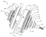
도 2는 도 1에 도시된 CVT의 부분 분해 단면도이다.
도 3은 CVT의 제2 실시예의 단면도이다.
도 4는 도 3에 도시된 CVT의 부분 분해 단면도이다.
도 5a는 CVT에 사용될 수 있는 스플라인 입력 디스크 구동기의 측면도이다.
도 5b는 도 5a에 도시된 디스크 구동기의 정면도이다.
도 6a는 CVT에 사용될 수 있는 스플라인 입력 디스크의 측면도이다.
도 6b는 도 6a에 도시된 스플라인 입력 디스크의 정면도이다.
도 7은 CVT와 함께 사용될 수 있는 캠 롤러 디스크를 도시한다.
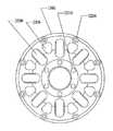
도 8은 CVT와 함께 사용될 수 있는 고정자를 도시한다.
도 9는 CVT와 함께 사용될 수 있는 스크래핑 스페이서(scraping spacer)의 사시도이다.
도 10은 CVT에 사용될 수 있는 시프트기 조립체(shifter assembly)의 단면도이다.
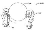
도 11은 CVT에 사용하기 위한 볼-레그 조립체의 사시도이다.
도 12는 볼 타입의 CVT에 사용될 수 있는 케이지의 사시도이다.
도 13은 CVT의 다른 실시예의 단면도이다.
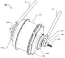
도 14는 CVT의 실시예가 적용된 자전거 허브의 사시도이다.
도 15는 도 14에 도시된 자전거 허브에 포함된 CVT의 실시예의 다양한 조립체의 평면도이다.
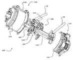
도 16은 도 15에 도시된 CVT의 일정 조립체의 부분 분해 사시도이다.
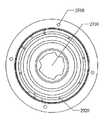
도 17은 도 15에 도시된 CVT의 일정 조립체의 평면도이다.
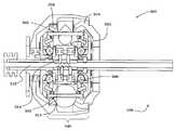
도 18은 도 17에 도시된 조립체의 단면 A-A를 따라 취한 단면도이다.
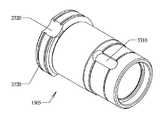
도 19는 도 15에 도시된 CVT와 함께 사용될 수 있는 시프트 캠 조립체의 일 실시예의 사시도이다.
도 20은 도 19에 도시된 시프트 캠 조립체의 평면도이다.
도 21은 도 20에 도시된 시프트 캠 조립체의 단면 B-B를 따라 취한 단면도이다.
도 22는 도 15에 도시된 CVT와 함께 사용될 수 있는 케이지 조립체의 사시도이다.
도 23은 도 22에 도시된 케이지 조립체의 정면도이다.
도 24는 도 22에 도시된 케이지 조립체의 우측면도이다.
도 25는 도 15에 도시된 CVT용 축력 발생 구성 요소의 부분 분해 정면도이다.
도 26은 도 25에 도시된 CVT 구성 요소의 단면 C-C를 따라 취한 단면도이다.
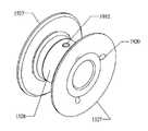
도 27은 도 15에 도시된 CVT와 함께 사용될 수 있는 정합 입력 샤프트와 토션 디스크의 분해 사시도이다.
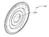
도 28은 도 27에 도시된 토션 디스크의 사시도이다.
도 29는 도 28에 도시된 토션 디스크의 좌측면도이다.
도 30은 도 28에 도시된 토션 디스크의 정면도이다.
도 31은 도 28에 도시된 토션 디스크의 우측면도이다.
도 32는 도 31에 도시된 토션 디스크의 단면 D-D를 따라 취한 단면도이다.
도 33은 도 27에 도시된 입력 샤프트의 사시도이다.
도 34는 도 33에 도시된 입력 샤프트의 좌측면도이다.
도 35는 도 33에 도시된 입력 샤프트의 평면도이다.
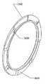
도 36은 도 15에 도시된 CVT와 함께 사용될 수 있는 로드 캠 디스크의 사시도이다.
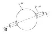
도 37은 도 15에 도시된 CVT와 함께 사용될 수 있는 볼 및 축 조립체의 평면도이다.
도 38은 도 37에 도시된 볼 및 축 조립체의 단면 E-E를 따라 취한 단면도이다.
도 39는 도 14에 도시된 자전거 허브의 평면도이다.
도 40은 도 15에 도시된 CVT와 도 14에 도시된 자전거 허브의 일정 구성 요소들을 도시하는, 도 39에 도시된 허브의 단면 F-F를 따라 취한 단면도이다.
도 41은 도 15에 도시된 CVT와 함께 사용될 수 있는 메인 샤프트의 사시도이다.
도 42는 도 41에 도시된 메인 샤프트의 평면도이다.
도 43은 도 42에 도시된 메인 샤프트의 단면 G-G를 따라 취한 단면도이다.
도 44는 도 14에 도시된 자전거 허브와 함께 사용될 수 있는 CVT의 다른 실시예의 평면도이다.
도 45는 도 44에 도시된 CVT의 단면 H-H를 따라 취한 단면도이다.
도 46은 도 14에 도시된 자전거 허브와 함께 사용될 수 있는 CVT의 단면도이다.1 is a cross-sectional view of one embodiment of a CVT.
FIG. 2 is a partial exploded cross-sectional view of the CVT shown in FIG. 1.
3 is a sectional view of a second embodiment of a CVT.
4 is a partial exploded cross-sectional view of the CVT shown in FIG. 3.
5A is a side view of a spline input disk driver that may be used for CVT.
FIG. 5B is a front view of the disk driver shown in FIG. 5A.
6A is a side view of a spline input disk that may be used for CVT.
FIG. 6B is a front view of the spline input disk shown in FIG. 6A.
7 shows a cam roller disc that can be used with the CVT.
8 shows a stator that can be used with the CVT.
9 is a perspective view of a scraping spacer that may be used with the CVT.
10 is a cross-sectional view of a shifter assembly that may be used for CVT.
11 is a perspective view of a ball-leg assembly for use in a CVT.
12 is a perspective view of a cage that may be used for the ball type CVT.
13 is a cross-sectional view of another embodiment of a CVT.
14 is a perspective view of a bicycle hub to which an embodiment of the CVT is applied.
FIG. 15 is a plan view of various assemblies of an embodiment of a CVT included in the bicycle hub shown in FIG. 14.
FIG. 16 is a partially exploded perspective view of the assembly of the CVT shown in FIG. 15.
FIG. 17 is a plan view of an assembly of the CVT shown in FIG. 15.
FIG. 18 is a cross-sectional view taken along section AA of the assembly shown in FIG. 17.
FIG. 19 is a perspective view of one embodiment of a shift cam assembly that may be used with the CVT shown in FIG. 15.
20 is a top view of the shift cam assembly shown in FIG. 19.
FIG. 21 is a cross-sectional view taken along the section BB of the shift cam assembly shown in FIG. 20.
FIG. 22 is a perspective view of a cage assembly that may be used with the CVT shown in FIG. 15.
FIG. 23 is a front view of the cage assembly shown in FIG. 22.
24 is a right side view of the cage assembly shown in FIG. 22.
FIG. 25 is a partial exploded front view of the axial force generating component for CVT shown in FIG. 15.
FIG. 26 is a cross-sectional view taken along section CC of the CVT component shown in FIG. 25.
FIG. 27 is an exploded perspective view of a mating input shaft and torsion disk that may be used with the CVT shown in FIG. 15.
FIG. 28 is a perspective view of the torsion disk shown in FIG. 27.
FIG. 29 is a left side view of the torsion disc shown in FIG. 28.
FIG. 30 is a front view of the torsion disk shown in FIG. 28.
FIG. 31 is a right side view of the torsion disc shown in FIG. 28.
FIG. 32 is a cross-sectional view taken along the section DD of the torsion disk shown in FIG. 31.
33 is a perspective view of the input shaft shown in FIG. 27.
FIG. 34 is a left side view of the input shaft shown in FIG. 33.
35 is a top view of the input shaft shown in FIG. 33.
FIG. 36 is a perspective view of a load cam disk that may be used with the CVT shown in FIG. 15.
FIG. 37 is a top view of a ball and shaft assembly that may be used with the CVT shown in FIG. 15.
FIG. 38 is a cross-sectional view taken along section EE of the ball and shaft assembly shown in FIG. 37.
39 is a top view of the bicycle hub shown in FIG. 14.
FIG. 40 is a cross-sectional view taken along the section FF of the hub shown in FIG. 39, showing certain components of the CVT shown in FIG. 15 and the bicycle hub shown in FIG. 14.
FIG. 41 is a perspective view of a main shaft that may be used with the CVT shown in FIG. 15.
FIG. 42 is a plan view of the main shaft shown in FIG. 41.
FIG. 43 is a cross-sectional view taken along the section GG of the main shaft shown in FIG. 42.
FIG. 44 is a top view of another embodiment of a CVT that may be used with the bicycle hub shown in FIG. 14.
FIG. 45 is a cross-sectional view taken along the cross section HH of the CVT shown in FIG. 44.
FIG. 46 is a cross-sectional view of a CVT that may be used with the bicycle hub shown in FIG. 14.
여기에 기술된 CVT의 실시예는 대체적으로 미국 특허 제6,241,636호, 제6,419,608호 및 제6,689,012호에 개시된 타입에 관한 것이다. 이들 특허 각각에 개시된 내용 전체는 여기에서 참고문헌으로 합체된다.Embodiments of CVT described herein relate generally to the types disclosed in US Pat. Nos. 6,241,636, 6,419,608, and 6,689,012. The entire contents disclosed in each of these patents are incorporated herein by reference.
도 1은 입력대 출력의 속도비를 변화시킬 수 있는 구형 타입 CVT(100)를 도해로 설명한다. CVT(100)는 CVT(100)의 중심을 통해 연장하여 자전거 프레임의 두개의 후방 드롭아웃(rear 드롭아웃)(10)을 지나는 중심 샤프트(105)를 갖는다. 각각이 중심 샤프트(105)의 해당 단부에 위치된 제1 캡 너트(106) 및 제2 캡 너트(107)는 중심 샤프트(105)를 드롭아웃에 부착시킨다. 비록 본 실시예가 자전거에 사용하기 위한 CVT(100)를 설명하고 있으나, CVT(100)는 변속기를 이용하는 어떠한 장치에도 구현될 수 있다. 설명을 위하여, 중심 샤프트(105)는 CVT의 다른 구성 요소들의 위치 및/또는 운동을 설명하기 위한 기준으로서 역할을 할 CVT의 종축을 한정한다. 여기에서 사용되는 바와 같이, 용어 "축", "축방향", "횡", "횡방향"은 중심 샤프트(105)에 의해 한정되는 종축과 동축 또는 평행한 방향 및 위치를 말한다. 용어 "반지름" 및 "반지름 방향"은 종축에서 직각으로 연장된 방향 및 위치를 말한다.1 illustrates a
도 1 및 도 2를 참조하면, 중심 샤프트(105)는 케이지 조립체(180), 입력 조립체(155) 및 출력 조립체(160)를 반지름 방향 및 횡 방향으로 지지한다. 본 실시예에서, 중심 샤프트(105)는 시프트 로드(112)를 수용하는 보어(199)를 포함한다. 후술되는 바와 같이, 시프트 로드(112)는 CVT(100)에서 변속비 시프트(a speed ratio shift)를 수행한다.1 and 2, the
CVT(100)는 베리에이터(140)를 포함한다. 베리에이터(140)는 입력 속도대 출력 속도의 비를 변화시키도록 구성된 임의의 메커니즘일 수 있다. 일 실시예에서, 베리에이터(140)는 입력 디스크(110), 출력 디스크(134), 경사 조절식 볼-레그 조립체(150) 및 아이들 조립체(125)를 포함한다. 입력 디스크(110)는 중심 샤프트(105)에 대해 회전 가능하고 동축으로 장착된 디스크일 수 있다. 입력 디스크(110)의 반지름 방향 외부 에지에서, 디스크는 접촉면(111)에서 종단되는 지점으로 각을 갖고 연장된다. 몇몇 실시예에서, 접촉면(111)은 접촉면(111)에 대해 지지할 입력 디스크(110)에 부착되는 링과 같은 별도 구조일 수 있다. 접촉면(111)은 입력 디스크(110)에 나사 결합되거나 억지 끼워 맞춤될 수 있으며, 또는 임의의 적절한 체결구 또는 접착제로 부착될 수 있다.
출력 디스크(134)는 출력 허브 쉘(138)에 억지 끼워 맞춤 또는 그와 다른 방식으로 부착되는 링일 수 있다. 몇몇 실시예에서, 입력 디스크(110) 및 출력 디스크(134)는 접촉면(111)으로부터 반지름 방향 외측으로 연장된 지지 구조체(113)를 갖는 데, 지지 구조체(113)는 반지름 방향으로 강성을 갖도록, CVT(100)의 축력에 대해 이들 부품의 컴플라이언스에 영향을 받지 않도록, 그리고 축력 메커니즘이 반지름 방향 외측으로 이동하도록 구조적으로 지지하여, CVT(100)의 길이를 줄이게 된다. 입력 디스크(110) 및 출력 디스크(134)는 베리에이터(140) 내의 윤활제가 CVT(100)를 통하여 순환하도록 하는 오일 포트(136, 135)를 가질 수 있다.The
몇몇 실시예에서의 허브 쉘(138)은 중심 샤프트(105)에 대해 회전 가능한 원통형 튜브이다. 허브 쉘(138)은 CVT(100)의 구성 요소들의 대부분이 내장되는 내측부와 CVT를 사용하는 어떠한 구성 요소, 설비 또는 차량에 연결하도록 구성된 외측부를 갖는다. 여기에서, 허브 쉘(138)의 외측부는 자전거에 구현되도록 구성된다. 그러나, CVT(100)는 회전 입력 및 출력 속도를 조절하기 원하는 임의의 기계에 사용될 수 있다.The
도 1, 도 2, 도 10 및 도 11을 참조하면, CVT는 입력 디스크(110)로부터 출력 디스크(134)로 토크를 전달하고 입력 속도대 출력 속도의 비를 변화시키기 위한 볼-레그 조립체(150)를 포함할 수 있다. 몇몇 실시예에서, 볼-레그 조립체(150)는 볼(101), 볼 축(102) 및 레그(103)를 포함한다. 축(102)은 볼(101)의 중심을 관통하여 형성된 보어를 통하여 연장된 대체로 원통형인 샤프트일 수 있다. 몇몇 실시예에서, 축(102)은 축(102) 상에 볼(101)을 정렬시키는 니들 또는 레이디얼 베어링을 거쳐 볼(101)의 보어의 표면과 계면을 이룬다. 축(102)은 레그(103)가 볼(101)의 위치를 이동시킬 수 있도록 보어가 끝나는 볼(101)의 측부를 지나 연장된다. 축(102)이 볼(101)의 에지를 지나 연장되는 지점에서, 레그(103)의 반지름 방향 외측 단부에 결합된다. 레그(103)는 볼 축(102)을 기울이는 반지름 방향 연장부이다.1, 2, 10, and 11, the CVT transfers torque from the
축(102)은 레그(103)의 반지름 방향 외측 단부에 형성된 보어를 관통하여 지나간다. 몇몇 실시예에서, 레그(103)는 축(102)이 레그(103)를 관통하여 지나가기 위한 보어에 형성된 모따기부를 포함하여, 축(102)과 레그(103)의 측부 사이의 접촉부에서 응력 집중을 감소시킨다. 이러한 감소된 응력은 볼-레그 조립체(150)의 수용력을 증가시켜 시프트 힘과 토크 반력을 흡수한다. 레그(103)는 e-링과 같은 클립 링에 의해 축(102) 상에 위치되거나 축(102) 상에 억지 끼워 맞춤될 수 있으나, 축(102)과 레그(103) 사이에 어떤 다른 고정 방식도 이용될 수 있다. 볼-레그 조립체(150)는 또한, 볼 축(102)의 각 단부에 부착된 구름 요소이고 CVT(100)의 다른 부품에 의해 정렬됨에 따라 축(102)의 구름 접촉을 제공하는 레그 롤러(151)를 포함할 수 있다. 몇몇 실시예에서, 레그(103)는 축(102)의 경사각을 제어하는 레그(103)의 반지름 방향 위치의 제어를 돕도록 반지름 방향 내측에 캠 휠(152)을 갖는다. 또 다른 실시예에서, 레그(103)는 레그(103)가 고정자(800)(도 8 참조) 내에 안내되고 지지되도록 하는 고정자 휠(1105)(도 11 참조)에 결합된다. 도 11에 도시된 바와 같이, 고정자 휠(1105)은 레그(103)의 종축에 대해 각을 가질 수 있다. 몇몇 실시예에서, 고정자 휠(1105)은 그의 중심축이 볼(101)의 중심과 교차하도록 구성된다.The
도 1, 도 2, 도 10 및 도 11을 다시 참조하면, 다양한 실시예에서, 볼(101)과 축(102) 사이의 계면은 아래의 다른 실시예에서 기술되는 임의의 베어링일 수 있다. 그러나, 볼(101)은 다른 실시예에서 축에 고정되고 축은 볼(101)과 함께 회전한다. 몇몇 이러한 실시예에서, (도시되지 않은) 베어링은 축(102) 상에 작용하는 횡력이 레그와, 또는 그 대안으로, (아래 다양한 실시예에서 기술되는) 케이지에 의해 반작용하게 되도록 축(102)과 레그(103) 사이에 위치된다. 몇몇 이러한 실시예에서, 축(102)과 레그(103) 사이에 위치된 베어링은 레이디얼 (볼 또는 니들) 베어링, 저널 베어링 또는 임의의 다른 타입의 베어링이거나, 혹은 적절한 메커니즘 또는 수단이다.Referring again to FIGS. 1, 2, 10, and 11, in various embodiments, the interface between
도 1, 도 2, 도 3, 도 4 및 도 10을 참조하여, 아이들 조립체(125)가 설명될 것이다. 몇몇 실시예에서, 아이들 조립체(125)는 아이들러(idler)(126), 캠 디스크(127) 및 아이들러 베어링(129)을 포함한다. 아이들러(126)는 대체로 원통형인 튜브이다. 아이들러(126)는 대체로 일정한 외경을 가지나, 다른 실시예에서 외경은 일정하지 않을 수 있다. 외경은 단부에서보다 중심부에서 작을 수 있거나, 혹은 중심에서 크고 단부에서 작을 수 있다. 다른 실시예에서, 외경은 다른 곳보다도 일 단부에서 크고 양 단부 사이의 변화가 시프트 속도 및 토크 요구에 따라서 선형 또는 비선형일 수 있다.With reference to FIGS. 1, 2, 3, 4, and 10, the
캠 디스크(127)는 아이들러(126)의 양 단부 모두 또는 어느 하나에 위치되어 캠 휠(152)과 상호 작용하여 레그(103)를 작동시킨다. 캠 디스크(127)는 예시된 실시예에서 볼록한 형상이나, 레그(103)의 원하는 운동을 발생시키는 임의의 형상일 수 있다. 몇몇 실시예에서, 캠 디스크(127)는 그의 축 방향 위치가 축(102)의 경사각을 조절하는 레그(103)의 반지름 방향 위치를 제어하도록 구성된다.The
몇몇 실시예에서, 캠 디스크(127)의 반지름 방향 내경부는 서로를 향하여 축 방향으로 연장되어 하나의 캠 디스크(127)를 다른 캠 디스크(127)에 부착시킨다. 여기서, 캠 연장부(128)는 중심 샤프트(105) 둘레에 원통을 형성한다. 캠 연장부(128)는 하나의 캠 디스크(127)에서부터 다른 캠 디스크(127)로 연장되고, 클립 링, 너트 또는 몇몇 다른 적절한 체결구에 의해 제 위치에 보유된다. 몇몇 실시예에서, 하나 또는 2개의 캠 디스크(127)는 캠 디스크 연장부(128) 상에 나사 결합되어 이를 제 위치에 고정시킨다. 예시된 실시예에서, 캠 디스크(127)의 볼록한 만곡부는 아이들 조립체(125)의 축 방향 중심에서부터 멀리 국부적으로 최대한 연장된 다음 반지름 방향 외측으로 그리고 다시 아이들 조립체(125)의 축 방향 중심을 향하여 축 방향 내측으로 연장된다. 이러한 캠 프로파일은 축 방향 극단에서 아이들 조립체(125)의 시프트 중에 일어날 수 있는 구속을 감소시킨다. 다른 캠 형상들도 사용될 수 있다.In some embodiments, the radially inner diameters of the
도 1의 실시예에서, 시프트 로드(112)는 CVT(100)의 변속비 시프트를 수행하게 한다. 중심 샤프트(105)의 보어(199) 내측에 위치된 시프트 로드(112)는 중심 샤프트(105)의 일 측 외부로 그리고 캡 너트(107)를 지나서 연장되는 나사 단부(109)를 갖는 긴 막대이다. 시프트 로드(112)의 타 단부는 시프트 로드(112) 내에 대체적으로 가로질러 장착되는 시프트 핀(114)을 포함하는 아이들 조립체(125)에서 그 내부로 연장된다. 시프트 핀(114)은 시프트 로드(112)가 아이들 조립체(125)의 축 방향 위치를 제어할 수 있도록 아이들 조립체(125)와 결합한다. 리드 스크루 조립체(115)는 중심 샤프트(105) 내의 시프트 로드(112)의 축 방향위치를 제어한다. 몇몇 실시예에서, 리드 스크루 조립체(125)는 시프트 로드(112)와 결합하도록 내경부의 일부에 나사가 형성되고 외경부에 한 세트의 테더 나사부(118)를 갖는 풀리일 수 있는 시프트 액추에이터(117)를 포함한다. 리드 스크루 조립체(115)는 임의의 수단에 의해 중심 샤프트(105) 상에서 축 방향 위치에 보유될 수 있고, 여기에서는 풀리 스냅 링(116)에 의해 제 위치에 보유된다. 테더 나사부(118)는 (도시되지 않은) 시프트 테더와 결합된다. 몇몇 실시예에서 시프트 테더는 표준 시프트 케이블이고, 다른 실시예에서 시프트 테더는 장력을 지지하여 시프트 풀리(117)를 회전시킬 수 있는 어떠한 임의의 테더일 수 있다.In the embodiment of FIG. 1,
도 1 및 도 2를 참조하면, 입력 조립체(155)는 베리에이터(140)로의 토크 전달을 허용한다. 입력 조립체(155)는 (도시되지 않은) 체인으로부터의 직선 운동을 회전 운동으로 변환시키는 스프로켓(156)을 포함한다. 비록 여기에서 스프로켓이 사용되었으나, CVT(100)의 다른 실시예에서는, 예를 들어 벨트로부터의 운동을 수용하는 풀리를 사용할 수 있다. 스프로켓(156)은 예시된 실시예에서 토크를 입력 디스크(110)로 전달하는 캠 로더(154)인 축력 발생 메커니즘으로 토크를 전달한다. 캠 로더(154)는 캠 디스크(157), 로드 디스크(158) 및 한 세트의 캠 롤러(159)를 포함한다. 캠 로더(154)는 토크를 스프로켓(156)으로부터 입력 디스크(110)로 전달하고, 또한 입력 디스크(110), 볼(101), 아이들러(126) 및 출력 디스크(134)에 대한 접촉력으로 분리되는 축력을 발생시킨다. 축력은 캠 로더(154)에 인가되는 토크의 양에 대체로 비례한다. 몇몇 실시예에서, 허브(138)가 자전을 하지만 스프로켓(156)이 토크를 전달하지 못할 때, 스프로켓(156)은 타성 진행 메커니즘(coasting mechanism)으로 작용하는 (상세히 도시되지 않은) 일방 클러치를 거쳐 캠 디스크(157)로 토크를 인가한다. 몇몇 실시예에서, 로드 디스크(158)는 입력 디스크(157)와 단일편으로 일체화될 수 있다. 다른 실시예에서, 캠 로더(154)는 출력 디스크(134)와 일체화될 수 있다.1 and 2, the
도 1 및 도 2에서, CVT(100)의 내부 구성 요소는 단부 캡(160)에 의해 허브 쉘(138) 내에 포함된다. 단부 캡(160)은 허브 쉘(138)의 개방 단부에 부착되고 캠 디스크(157), 중심 샤프트(105) 및 시프트 로드(112)가 통과하도록 중심을 관통하는 보어를 갖는 대체로 평평한 디스크이다. 단부 캡(160)은 허브 쉘(138)에 부착되어 캠 로더(154)에 의해 발생되는 축력에 대해 반작용하는 역할을 한다. 단부 캡(160)은 예를 들어, 알루미늄, 티타늄, 강, 또는 고강도 열가소성 혹은 열경화성 플라스틱과 같이 축력에 대해 반작용할 수 있는 임의의 재료로 형성될 수 있다. 단부 캡(160)은 (도시되지 않은) 체결구에 의해 허브 쉘(138)에 체결되지만, 단부 캡(160)은 또한 허브 쉘(138)에 나사 결합되거나 이와 달리 그에 부착될 수도 있다. 단부 캡(160)은 캠 로더(154)를 향하는 그의 측부 상에 일정 반지름을 따라 형성된, 예비 로더(161)가 내장되는 홈을 포함한다. 예비 로더(161)는 매우 낮은 토크 레벨로 초기 클램핑 힘을 제공하는 스프링일 수 있다. 예비 로더(161)는, 스프링 또는 O-링과 같은 탄성 재료와 같이, 초기 힘을 캠 로더(154)에 그리고 그에 따라 입력 디스크(134)에 공급할 수 있는 임의의 장치일 수 있다. 예비 로더(161)는 파형 스프링(wave-spring)일 수 있는 데 이러한 스프링은 높은 스프링 상수를 갖고 그의 수명에 걸쳐 높은 레벨의 탄성을 유지하기 때문이다. 여기에서, 예비 로더(161)는 스러스트 와셔(162)와 스러스트 베어링(163)에 의해 단부 캡(160)에 직접 장착된다. 본 실시예에서, 스러스트 와셔(162)는 예비 로더(161)의 홈을 덮고 스러스트 베어링(163)을 위한 스러스트 레이스를 제공하는 전형적인 링 와셔이다. 스러스트 베어링(163)은, 복합식 스러스트 레이디얼 베어링과 비교하였을 때 높은 레벨의 스러스트 용량을 갖고, 구조적 강성을 향상시키고, 공차 요구 및 비용을 줄이는 니들 스러스트 베어링일 수 있으나, 임의 다른 타입의 스러스트 베어링 또는 복합식 베어링이 사용될 수 있다. 특정 실시예에서, 스러스트 베어링(163)은 볼 스러스트 베어링이다. 캠 로더(154)에 의해 발현된 축력은 스러스트 베어링(163) 및 스러스트 와셔(162)를 통하여 단부 캡(160)에 반작용하게 된다. 단부 캡(160)은 CVT(100)의 구조를 완성하도록 허브 쉘(138)에 부착된다.1 and 2, the internal components of
도 1 및 도 2에서, 캠 디스크 베어링(172)이 중심 샤프트(105)에 대해 반지름 방향 위치에 캠 디스크(157)를 보유하는 한편, 단부 캡 베어링(173)은 캠 디스크(157)와 단부 캡(160)의 내경부 사이에 반지름 방향 정렬을 유지시킨다. 여기에서, 캠 디스크 베어링(172) 및 단부 캡 베어링(173)은 니들 롤러 베어링이지만, 다른 타입의 레이디얼 베어링도 사용될 수 있다. 니들 롤러 베어링의 사용은 축 방향 부유(float)가 증가되는 것을 허용하고 탑승자와 스프로켓(156)에 의해 발현되는 바인딩 모멘트를 수용한다. CVT(100)의 다른 실시예 또는 여기에서 기술된 임의의 다른 실시예에서, 캠 디스크 베어링(172) 및 단부 캡 베어링(173)의 각각 또는 어느 하나는 상호 보완하는 한 쌍의 복합식 레이디얼-스러스트 베어링에 의해 대체될 수도 있다. 이러한 실시예에서, 레이디얼 스러스트 베어링은 반지름 방향 지지를 제공할 뿐만 아니라 추력을 흡수할 수 있어서, 스러스트 베어링(163)을 도울 수 있고 적어도 부분적으로 부하를 덜 수 있다.1 and 2, the cam disk bearing 172 holds the
도 1 및 도 2를 다시 참조하면, 중심 샤프트(105)에 대해 동축으로 장착된 지지부재이고 중심 샤프트(105)와 허브 쉘(138)의 폐쇄 단부의 내경부 사이에 보유된 축(142)은 중심 샤프트(105)에 대한 축 방향으로 정렬되어 허브 쉘(138)을 보유한다. 축(142)은 중심 샤프트(105)와 각도가 정렬되어 고정된다. 여기에서 키(144)가 축(142)의 각도가 정렬되도록 그를 고정시키지만, 이러한 고정은 관련 기술 분야에서 숙련자에게 알려진 임의의 수단에 의해 수행될 수 있다. 레이디얼 허브 베어링(145)은 축(142)과 허브 쉘(138)의 내경부 사이에 끼워져 허브 쉘(138)의 축 방향 정렬과 반지름 방향 위치를 유지시킨다. 허브 베어링(145)은 캡슐화 축 캡(143)에 의해 제 위치에 보유된다. 축 캡(143)은 중심 샤프트(105) 둘레에 끼워지는 중심 보어를 갖는 디스크이고, 여기에서는 허브 쉘(138)에 체결구(147)로 부착된다. 허브 스러스트 베어링(146)은 허브 쉘(138)과 케이지(189) 사이에 끼워져 케이지(189)와 허브 쉘(138)의 축 방향 위치를 유지한다.Referring again to FIGS. 1 and 2, the
도 3, 도 4 및 도 10은 전술된 CVT(100)의 다른 실시예인 CVT(300)을 도시한다. 많은 구성 요소들이 본 도면과 전술된 CVT(100) 실시예 사이에서 유사하다. 여기에서, 입력 및 출력 디스크(310, 334)의 각도는 각각 감소되어 큰 강도가 축력에 저항하게 하고 CVT(300)의 전체 반지름 방향의 직경을 감소시킨다. 본 실시예는 아이들 조립체(325)의 축 방향 운동을 수행하는 리드 스크루 메커니즘이 시프트 막대(312) 상에 형성되는 다른 시프트 메커니즘을 도시한다. 리드 스크루 조립체는 아이들 조립체(325) 내에 또는 근처에 있는 시프트 막대(312)의 단부 상에 형성된 한 세트의 리드 나사부(313)이다. 하나 이상의 아이들 조립체 핀(314)은 캠 디스크 연장부(328)에서 리드 나사부(313) 내로 반지름 방향으로 연장되고 시프트 막대(312)가 회전함에 따라 축 방향으로 이동한다.3, 4 and 10 illustrate a
도시된 실시예에서, 아이들러(326)는 일정한 외경을 갖지 않고 오히려 아이들러(326)의 단부에서 외경이 증가한다. 이는 아이들러(326)를 중심 위치에서 축방향으로 멀리 밀어내려는 자전 접촉과 동적 접촉력을 통하여 발현되는 아이들러(326)의 힘에 대해 아이들러(326)가 저항하게 한다. 그러나, 이는 단지 일 예일 뿐이고 아이들러(326)의 외경은 아이들러(326)에 의해 느껴지는 자전력에 대해 반작용하고 CVT(300)의 시프트를 돕기 위하여 설계자가 원하는 임의의 방식으로 변화될 수 있다.In the illustrated embodiment, the idler 326 does not have a constant outer diameter but rather increases in outer diameter at the end of the
이제 도 5a, 도 5b, 도 6a 및 도 6b를 참조하면, 2개의 부분으로 된 디스크는 스플라인 디스크(600) 및 디스크 구동기(500)로 형성된다. 디스크 구동기(500) 및 스플라인 디스크(600)는 디스크 구동기(500)에 형성된 스플라인(510)과 스플라인 디스크(600)에 형성된 스플라인 보어(610)를 통하여 서로 끼워진다. 스플라인(510)은 스플라인 보어(610) 내에 끼워져 디스크 구동기(500)와 스플라인 디스크(600)가 CVT(100), CVT(300) 또는 임의의 다른 구형 CVT에 사용하기 위한 디스크를 형성한다. 스플라인 디스크(600)는 시스템 내의 컴플라이언스에 대비하여 베리에이터(140, 340)가 반지름 방향 균형 위치를 찾도록 하여 베리에이터(140, 340)의 구성 요소의 제작 공차에 대한 민감성을 감소시킨다.Referring now to FIGS. 5A, 5B, 6A, and 6B, a two part disk is formed of a
도 7은 CVT(100), CVT(300), 다른 구형 CVT 또는 어떤 다른 타입의 CVT에 사용될 수 있는 캠 디스크(700)를 도시한다. 캠 디스크(700)는 그의 반지름 방향 외측 에지에 형성된 캠 채널(710)을 갖는다. 캠 채널(710)은 본 실시예에서 (베어링 볼과 같은) 구이지만 캠 채널(710)의 형상과 조합한 임의의 다른 형상일 수 있는 (도시되지 않은) 한 세트의 캠 롤러를 내장하여, 토크를 토크 및 축력 성분으로 변환하여 CVT에 인가된 토크에 비례하는 양으로 베리에이터(140, 340)에 인가된 축력을 완화시킨다. 다른 이러한 형상은 원통형 롤러, 배럴 형상의 롤러, 비대칭 형상의 롤러 또는 임의의 다른 형상을 포함한다. 여러 실시예에서 캠 디스크 채널(710)을 위해 사용되는 재료는 캠 디스크(700)가 받게 될 부하에서 과도한 변형 또는 영구 변형에 저항하기에 충분히 강한 것이 바람직하다. 높은 토크의 인가에는 특별한 경화가 필요할 수 있다. 몇몇 실시예에서, 캠 디스크 채널(710)은 40 HRC 이상의 로크웰 경도값으로 경화된 탄소강으로 제작된다. 캠 로더(도 1의 154, 또는 임의의 다른 타입의 캠 로더)의 작동 효율은 경도값에 영향을 받을 수 있으며, 일반적으로 경도를 증가시키면 효율이 증가한다. 그러나, 높은 경도는 캠 부하 부품에서 취성을 나타낼 수 있으며 또한 높은 비용을 초래하게 된다. 몇몇 실시예에서 경도는 50 HRC 이상인 반면, 다른 실시예에서는 55 HRC 이상, 60 HRC 이상 및 65 HRC 이상이다.7 shows a
도 7은 등각 캠의 일 실시예를 도시한다. 즉, 캠 채널(710)의 형상은 캠 롤러의 형상에 합치한다. 채널(710)이 롤러에 합치하기 때문에, 채널(710)은 베어링 롤러의 리테이너 역할을 하여, 케이지 요소에 대한 요구가 제거된다. 도 7의 실시예는 일 방향 캠 디스크(700)이지만, 캠 디스크는 CVT(1300)에서와 같이 양 방향 캠일 수 있다(도 13 참조). 베어링 롤러 리테이너에 대한 필요성을 제거한 것은 CVT의 설계를 단순하게 한다. 또한, 등각 캠 채널(710)은 베어링 롤러와 채널(710) 사이의 접촉 응력이 감소되도록 하여, 베어링 롤러의 크기 및/또는 개수를 줄이거나, 또는 재료 선택에 큰 융통성을 제공한다.7 illustrates one embodiment of a conformal cam. That is, the shape of the
도 8은 구형 CVT(100, 300 및 다른 타입의 CVT)에서 베리에이터(140, 340)의 케이지(189)의 강성인 지지 구조체를 형성하는 데 사용되는 케이지 디스크(800)를 도시한다. 케이지 디스크(800)는 시프트 중에 레그(103)가 반지름 방향 내외측으로 이동함에 따라 레그(103)를 안내하도록 형성된다. 케이지 디스크(800)는 또한 축(102)의 각도가 정렬되도록 한다. 몇몇 실시예에서, 각각의 축(102)에 대한 2개의 케이지 디스크(800)의 해당 홈이 베리에이터(140, 340) 내의 시프트 힘을 줄이도록 각도 방향으로 다소 오프셋된다. 2개의 케이지 디스크(800)은 제1 케이지 디스크 및 제2 케이지 디스크의 일 예에 해당한다. 2개의 케이지 디스크(800)의 해당 홈은 제1 방사상 홈 및 제2 방사상 홈의 일 예에 해당한다.8 shows
레그(103)는 고정자 내의 슬롯에 의해 안내된다. 레그(103) 상의 레그 롤러(151)는 고정자 내의 원형 프로파일을 따라간다. 레그 롤러(151)는 시프트 힘 또는 견인 접촉 자전력에 의해 부가된 병진 방향 힘에 대항하기 위한 병진 방향 반작용점을 일반적으로 제공한다. 각각의 레그 롤러(151) 뿐만 아니라 레그(103)는 CVT 비가 변할 때 평면 운동을 하고 볼(101)을 중심으로 하는 원형의 외피(a circular envelope)를 따라 간다. 레그 롤러(151)가 레그(103)의 중심으로부터 오프셋되어 있기 때문에, 레그 롤러(151)는 유사하게 오프셋된 외피를 따라간다. 레그 롤러(151)의 평면 운동과 조화를 이루도록 각각의 고정자에 양립 가능한 프로파일을 생성하기 위하여, 롤러가 각각의 레그(103)에서 오프셋되는 동일한 양만큼 홈의 중심으로부터 오프셋된 원형의 절단부가 요구된다. 이러한 원형의 절단부는 회전 톱 커터로 수행될 수 있으나, 이는 각각의 홈에서 개별 절단을 요구한다. 이러한 절단부가 독립적이기 때문에, 고정자 사이의 변동에 더하여, 단일 고정자에서 하나의 홈으로부터 다음 홈으로 공차 변동의 확률이 있다. 이러한 추가의 기계 가공 단계를 없애는 방법은 래치 회전 작업에 의해 발생될 수 있는 단일 프로파일을 제공하는 것이다. 환상의 선반 절단부는 하나의 회전 작동 시에 이러한 단일 프로파일을 생성할 수 있다. 환상 절단부의 중심은 볼(101) 위치의 중심에서부터 멀리 반지름 방향으로 조절되어 레그 롤러(103)의 오프셋에 대해 보상한다.
이제 도 1, 도 9 및 도 12를 참조하면, 스페이서(1210)가 제1 케이지 디스크 및 제2 케이지 디스크의 일 예에 해당하는 2개의 케이지 디스크(1220)를 지지하고 이격시키는 몇몇 CVT와 함께 사용하기 위해 윤활이 향상된 윤활 스페이서(900)를 구현하는 케이지 조립체(1200)의 다른 실시예가 도시된다. 도시된 실시예에서, 동력 변속기 요소를 위한 지지 구조체, 이 경우에 케이지(389)는 하나 이상의 윤활 스페이서(900)를 포함하는 다수의 스페이서(1210)에 케이지 체결구(1230)로 입력 및 출력측 케이지 디스크(1220)를 부착시킴으로써 형성된다. 본 실시예에서, 케이지 체결구(1230)는 스크루이지만 임의 타입의 체결구 또는 체결 방법일 수 있다. 윤활 스페이서(900)는 허브 쉘(138)의 표면에서 윤활제를 긁어내고 윤활제를 다시 베리에이터(140 또는 340)의 중심 요소로 향하도록 하는 스크래퍼(910)를 갖는다. 몇몇 실시예의 윤활 스페이서(900)는 윤활제를 가장 많이 이용하는 영역을 향하여 윤활제가 유동하는 것을 돕도록 통로(920)들을 또한 갖는다. 몇몇 실시예에서, 통로(920)들 사이의 스페이서(900)의 일부는 윤활제가 통로(920)를 향하여 유동하도록 하는 상승된 쐐기부(925)를 형성한다. 스크래퍼(910)는 스페이서(900)와 일체로 형성되거나, 또는 윤활제를 허브 쉘(138)에서 잘 긁어내도록 고무를 포함하는 그러나 그에 한정되지 않는 스페이서(900)의 재료와 상이한 재료로 별개로 제작될 수 있다. 스페이서(1210)와 윤활 스페이서(900)의 단부는 케이지 디스크(1220)와 정합하기 위한 표면을 형성하도록 직각으로 연장된 플랜지 같은 베이스(1240)에서 종단된다. 도시된 실시예의 베이스(1240)는 케이지 디스크(1240)를 향하는 측부 상에서 대체로 평평하지만 볼(101)을 대면하는 측부 상에서는 둥글게 되어 레그 롤러(151)가 주행하는 전술된 만곡된 표면을 형성한다. 베이스(1240)는 또한 레그가 주행하는 채널을 그들의 이동 전체에 대해 형성한다.Referring now to FIGS. 1, 9, and 12, the
윤활 시스템 및 방법의 실시예가 도 3, 도 9 및 도 10을 참조하여 이제 설명될 것이다. 볼(101)이 자전함에 따라, 윤활제는 볼(101)의 적도를 향하여 유동하려고 하여, 윤활제는 허브 쉘(138)에 대해 분무된다. 일부 윤활제는 가장 큰 직경을 갖는 허브 쉘(138)의 내벽에 떨어지지 않지만, 원심력이 이러한 윤활제가 허브 쉘(138)의 최대 내측 직경부를 향하여 유동하도록 한다. 스크래퍼(910)는 허브 쉘(138)의 내측에 축적된 윤활제를 제거하도록 수직으로 위치된다. 중력은 윤활제를 V 형상의 쐐기(925)의 각 측부 아래로 그리고 통로(920) 내로 끌어당긴다. 스페이서(900)는 통로(920)의 반지름 방향 내측 단부가 아이들러(126)와 캠 디스크(127)의 근처에서 종단하도록 위치된다. 이러한 방식으로, 아이들러(126) 및 캠 디스크(127)는 허브 쉘(138) 내에서 순환하는 윤활제를 수용한다. 일 실시예에서, 스크래퍼(910)는 대략 천분의 30 인치만큼 허브 쉘(138)에서 틈새가 생기도록 치수가 정해진다. 물론 이러한 틈새는 상이한 응용예에 대해서는 더 크거나 작을 수 있다.Embodiments of the lubrication system and method will now be described with reference to FIGS. 3, 9, and 10. As the
도 3 및 도 10에 도시된 바와 같이, 캠 디스크(127)는 아이들러(226)를 대면하는 그의 측부가 통로(920)로부터 낙하하는 윤활제를 수용하여 캠 디스크(127)와 아이들러(226) 사이의 공간으로 윤활제를 향하게 하도록 경사지게 구성될 수 있다. 윤활제가 아이들러(226) 상으로 유동한 다음, 윤활제는 윤활제의 일부가 축(102)에 분무되는 아이들러(226)의 최대 직경부를 향하여 유동한다. 윤활제의 일부는 통로(920)에서 아이들러(226) 상으로 낙하한다. 이러한 윤활제는 볼(101)과 아이들러(226) 사이의 접촉부뿐만 아니라 아이들러(226)를 윤활한다. 아이들러(226) 각 측부 상의 경사에 의해, 윤활제의 일부는 아이들러(226)의 에지를 향하여 원심력에 의해 유동하여 반지름 방향으로 분무된다.As shown in FIGS. 3 and 10, the
도 1, 도 3 및 도 10을 참조하면, 몇몇 실시예에서, 아이들러(126, 226)에서 축(102)을 향하여 분무되는 윤활제는 윤활제를 수용하여 이를 볼(101)의 내측으로 펌핑하는 홈(345)에 낙하한다. 윤활제의 일부는 입력 디스크(110) 및 출력 디스크(134)가 볼(101)과 접촉하는 접촉면(111) 상에 또한 낙하한다. 윤활제가 볼(101)의 일 측부 상을 나갈 때, 윤활제는 원심력 하에서 볼(101)의 적도를 향하여 유동한다. 이러한 윤활제의 일부는 입력 디스크(110)와 볼(101)의 접촉면(111)과 접촉하여, 볼(101)의 적도를 향하여 유동한다. 윤활제의 일부는 볼(101)에서부터 멀리 향하는 출력 디스크(134)의 측부를 따라서 반지름 방향으로 유동하여 나간다. 몇몇 실시예에서, 입력 디스크(110) 및/또는 출력 디스크(134)에는 윤활 포트(136, 135)가 각각 구비된다. 윤활 포트(135, 136)는 윤활제가 허브 쉘(138)의 최대 내측 직경부를 향하도록 한다.1, 3, and 10, in some embodiments, the lubricant sprayed toward the
도 13은 2개의 캠-로더(1354)를 갖는 CVT(1300)의 실시예를 도시하는 데, 2개의 캠-로더(1354)는 CVT(1300) 내의 축력의 발생 및 분배를 행한다. 여기에서, 캠 로더(1354)는 입력 디스크(1310) 및 출력 디스크(1334)에 인접하게 위치된다. CVT(1300)는 어떻게 토크가 입력 디스크(1310)를 거쳐 출력 디스크(1334)를 통하여 외부로 공급될 수 있는가, 혹은 토크가 출력 디스크(1334)를 통하여 입력되고 입력 디스크(1310)를 통하여 출력되도록 역전될 수 있는가를 도시한다.FIG. 13 shows an embodiment of a
도 14는 여기에서 기술된 CVT의 실시예의 특징을 포함하도록 구성된 자전거 허브(1400)를 도시한다. 허브(1400)의 몇몇 구성 요소는 전술된 구성 요소와 동일하여, 이러한 구성 요소의 추가 설명은 제한될 것이다. 허브(1400)는 허브 캡(1460)에 결합되는 허브 쉘(138)을 포함한다. 실시예에서, 허브(1400)는 또한 허브 캡(1460)에 대향하는 허브 쉘(138)의 단부를 밀봉하는 단부 캡(1410)을 포함한다. 허브 쉘(138), 허브 캡(1460) 및 단부 캡(1410)은 구조적 강도 및 강성을 제공하는 재료로 제작된다. 이러한 재료는, 예를 들어, 강, 알루미늄, 마그네슘, 고강도 플라스틱 등을 포함한다. 몇몇 실시예에서, 기술의 주어진 응용예의 특정 요구에 따라서, 다른 재료가 적절할 수 있다. 예를 들어, 허브 쉘(138)은 복합물, 열가소성 물질 등으로 만들어질 수 있다.14 illustrates a
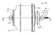
이제 도 14를 참조하면, 도시된 허브(1400)의 내부에는 여기에서 설명된 CVT의 실시예가 내장된다. 메인 샤프트(105)는 허브(1400)를 지지하고 자전거 또는 다른 차량 또는 장치의 드롭아웃(10)과의 부착에 대비한다. 본 실시예의 메인 샤프트(105)는 도 41 내지 도 43을 참조하여 더 상세하게 설명된다. 몇몇 실시예에서, 도 15 내지 도 18에 도시된 바와 같이, CVT(1500)는 나사 단부(109)를 갖는 로드(112)가 구비된 시프트 메커니즘을 포함한다. 너트(106, 107)는 드롭아웃(10)을 메인 샤프트(105)에 잠근다. 도 14의 실시예에서, 허브(1400)는 토크 입력을 CVT(1500) 내에 전달하기 위해 입력 샤프트 (도 33 및 도 40 참조)에 작동식으로 결합된 자유휠(1420)을 포함한다. 여기에서 기술된 CVT의 여러 실시예 및 특징이 자전거 응용예를 참조로 논의되었으나 용이하게 인식 가능한 변형예를 통하여 CVT와 그의 특징이 변속기를 사용하는 임의의 차량, 기계 또는 장치에 사용될 수 있음에 유의하여야 한다.Referring now to FIG. 14, an embodiment of the CVT described herein is embedded within the
도 15 및 도 16을 참조하면, 일 실시예에서, CVT(1500)는 토크를 (여기에서 볼(101)로 도시된) 한 세트의 구형 견인 롤러로 전달하기 위한 입력 디스크(1545)를 갖는다. 도 16은 CVT(1500)의 부분 분해도이다. 볼(101)은 토크를 출력 디스크(1560)로 전달한다. CVT(1500)의 다양한 특징을 명확하게 설명하기 위하여 하나의 볼(101)이 본 실시예에서 설명되었으나, CVT의 다양한 실시예는 각각의 특별한 응용예의 토크, 무게, 치수의 요구 사항에 따라 대략 2개 내지 16개 이상의 볼(101)을 사용한다. 상이한 실시예는 2개, 3개, 4개, 5개, 6개, 7개, 8개, 9개, 10개, 11개, 12개, 13개, 14개, 15개, 16개 또는 그 이상의 볼(101)을 사용한다. 메인 샤프트(105)에 대해 동축으로 장착된 아이들러(1526)는 볼(101)과 접촉하여 그를 지지하고, 메인 샤프트(105) 둘레에서 그의 반지름 방향 위치를 유지시킨다. 몇몇 실시예의 입력 디스크(1545)는 CVT(1500) 내에 윤활제의 순환을 용이하게 하도록 윤활 포트(1590)를 갖는다.15 and 16, in one embodiment, the
도 37 및 도 38을 더 참조하면, 볼(101)은 축(3702)에 대해 자전한다. 레그(103) 및 시프트 캠(1527)은 함께 작동하여 축(3702)의 위치를 시프트하는 레버의 역할을 하는데, 이러한 시프트의 결과 볼(101)이 기울어지고 그에 따라서 이미 전술된 바와 같이 변속비의 시프트가 일어난다. 케이지(1589)(도 22 내지 도 24 참조)는 시프트 캠(1527)이 레그(103)의 반지름 방향 운동을 가동시킴에 따라 레그(103)를 지지하고 정렬할 대비를 한다. 일 실시예에서, 케이지는 고정자 스페이서(1555)에 의해 결합된 고정자(1586, 1587)를 포함한다. 고정자(1586, 1587)는 제1 케이지 디스크 및 제2 케이지 디스크의 일 예에 해당한다. 다른 실시예에서는 다른 케이지(180, 389, 1200)가 채용된다.Referring further to FIGS. 37 and 38, the
도 41 내지 도 43을 더 참조하면, 도시된 실시예에서, 케이지(1589)는 메인 샤프트(105) 둘레에 동축으로 회전 불가능하게 장착된다. 고정자(1586)는 본 실시예에서 메인 샤프트(105)의 플랜지(4206)에 단단히 부착된다. 추가의 플랜지(1610)는 고정자(1587)를 제 위치에 보유한다. 키(1606)는 키(1606)를 수용하는 키 시트(1608)를 갖는 메인 샤프트(105)에 플랜지(1610)를 결합시킨다. 물론, 관련 기술 분야의 통상의 지식을 가진 자는 메인 샤프트(105)를 플랜지(1610)에 결합하는, 또는 고정자(1586, 1587)를 플랜지(1620, 4206)에 결합하는 많은 동등한 그리고 다른 방법이 있다는 것을 쉽게 인식할 것이다. 일정 실시예에서, 메인 샤프트(105)는 플랜지(1610)를 축 방향으로 위치시키고 구속하는 역할을 하는 견부(4310)를 포함한다.With further reference to FIGS. 41-43, in the illustrated embodiment, the
단부 캡(1410)은 자체가 플랜지(1610) 위에 장착되는 레이디얼 베어링(1575) 상에 장착된다. 일 실시예에서, 레이디얼 베어링(1575)은 지면의 반력으로부터의 하중을 지지하고 메인 샤프트(105)에 허브 쉘(138)을 반지름 방향으로 정렬하는 앵귤러 콘택트 베어링(angular contact bearing)이다. 몇몇 실시예에서, 허브(1400)는 메인 샤프트(105)의 일 단부 또는 양 단부에 시일을 포함한다. 예를 들어, 여기에서 허브(1400)는 허브 쉘(138) 및 단부 캡(1410)이 함께 결합된 단부에 시일(1580)을 갖는다. 더욱이, 출력 측에 축력을 미리 인가하고 허브 쉘(138)의 축 방향 위치를 유지하기 위하여, 허브(1400)는 스페이서(1570)와, 고정자(1587)와 레이디얼 베어링(1575) 사이의 (도시되지 않은) 니들 스러스트 베어링을 포함할 수 있다. 스페이서(1570)는 플랜지(1610) 둘레에 동축으로 장착된다. 몇몇 실시예에서, 니들 스러스트 베어링은 사용되지 않고, 이러한 경우에 레이디얼 베어링(1575)이 스러스트 하중을 처리하도록 구성된 앵귤러 콘택트 베어링일 수 있다. 관련 기술 분야에서 통상의 지식을 가진 자는 다른 수단이 스페이서(1570), 니들 스러스트 베어링 및 레이디얼 베어링이 제공하는 레이디얼 및 스러스트 하중을 지탱하는 역할을 제공한다는 것을 쉽게 인식할 것이다.
도 14, 도 15 및 도 16을 참조하면, 도시된 실시예에서, 허브(1400)용 베리에이터(1500)는 일 단부가 토션 디스크(1525)에 작동식으로 결합된 입력 샤프트(1505)를 포함한다. 입력 샤프트(1505)의 타 단부는 자유휠 캐리어(1510)를 거쳐 자유휠(1420)에 작동식으로 결합된다. 토션 디스크(1525)는 경사부(3610)를 갖는 로드 캠 디스크(1530)에 토크를 전달하도록 구성된다(도 36 참조). 로드 캠 디스크(1530)는 제2 로드 캠 디스크(1540)에 작용하는 한 세트의 롤러(2504)(도 25 참조)에 토크 및 축력을 전달한다. 입력 디스크(1545)는 토크 및 축력 입력을 수용하도록 제2 로드 캠 디스크(1540)에 결합된다. 몇몇 실시예에서, 롤러(2504)는 롤러 케이지(1535)에 의해 제 위치에 보유된다.14, 15, and 16, in the illustrated embodiment, the
잘 알려진 바와 같이, 많은 견인 타입의 CVT는 일정 레벨의 토크를 전달할 때 볼(101)과 입력 디스크(1545) 및/또는 출력 디스크(1560) 사이의 미끄러짐을 방지하는 클램핑 메커니즘을 이용한다. 클램핑 메커니즘의 제공은 여기에서 종종 축력을 발생시키는 것 또는 축력 발생기를 제공하는 것을 가리킨다. 롤러(2504)를 통하여 로드 캠(1540)과 함께 작동하는 로드 캠 디스크(1530)의 전술된 구성은 축력 발생 메커니즘이다. 그러나, 축력 발생 장치 또는 부조립체가 CVT 내에서 축력을 생성함에 따라, 몇몇 실시예에서 CVT 자체에 반작용하게 되는 반력이 또한 생성된다. 도 25 및 도 26을 더 참조하면, CVT(1500)의 도시된 실시예에서, 반력은 제1 및 제2 레이스(1602, 1603)를 각각 갖는 스러스트 베어링에 의해 적어도 부분적으로 반작용하게 된다. 도시된 실시예에서, 베어링 요소는 도시되지 않았으나 볼, 롤러, 배럴 형상의 롤러, 비대칭 롤러 또는 임의의 다른 타입의 롤러일 수 있다. 더욱이, 몇몇 실시예에서, 레이스(1602)의 하나 또는 둘은 다양한 베어링 레이스 재료, 예를 들어 강, 베어링 강, 세라믹 또는 베어링 레이스에 사용되는 임의의 다른 재료로 제작된다. 제1 레이스(1602)는 토션 디스크(1525)에 대항하여 접하고, 제2 레이스(1603)는 허브 캡(1460)에 대항하여 접한다. 도시된 실시예의 허브 캡(1460)은 축력 메커니즘이 발생시키는 반력을 흡수하는 것을 돕는다. 몇몇 실시예에서, 축력 발생은 파형 스프링(1515) 또는 토션 스프링(2502)과 같은 축 방향 스프링의 하나 이상의 예비 로더를 더 제공하는 것을 포함한다(도 25에 대한 아래의 설명을 참조).As is well known, many traction types of CVT utilize a clamping mechanism that prevents slippage between the
도 15 내지 도 18, 도 22 내지 도 24 및 도 43을 참조하여, CVT(1500)의 일정한 부조립체를 설명한다. 고정자(1586)는 메인 샤프트(105)의 견부(4208) 상에 장착되고 메인 샤프트(105)의 플랜지(4206)에 대항하여 접한다. 고정자(1587)는 플랜지(1610)의 견부(1810) 상에 장착된다. 여기에서, (도시되지 않은) 스크루는 플랜지(4206)를 고정자(1586)에 부착시키고 플랜지(1610)를 고정자(1587)에 부착시키지만, 다른 실시예에서 고정자(1587)는 비록 고정자(1587)가 임의의 방법 또는 수단에 의해 견부(1810)에 부착될 수 있더라도 견부(1810) 상에 나사 결합된다. 플랜지(1610, 4206)가 메인 샤프트(105)에 회전 불가능하게 고정되어 있기 때문에, 다른 것들 중에서 고정자(1586, 1587)로 만들어진 케이지(1589)는 본 실시예에서 메인 샤프트(105)에 회전 불가능하게 부착된다. 고정자 스페이서(1555)는 케이지(1589)에 추가의 구조적 강도 및 강성을 제공한다. 더욱이, 고정자 스페이서(1555)는 고정자(1586, 1587) 사이의 정밀한 축 방향 간격을 구현하는 것을 돕는다. 고정자(1586, 1587)는 안내 홈(2202)을 통하여 레그(103) 및 축(3702)을 안내 및 지지한다. 안내 홈(2202)은 제1 방사상 홈 및 제2 방사상 홈의 일 예에 해당한다.With reference to FIGS. 15-18, 22-24, and 43, certain subassemblies of
이제 도 15 내지 도 21, 도 37 및 도 38을 참조하면, 볼(101)은 축(3702)에 대해 자전하고 아이들러(1526)와 접촉한다. 메인 샤프트(105) 둘레에 동축으로 장착된 베어링(1829)은 아이들러(1526)를 그의 반지름 방향 위치에 대해 지지하는 데, 이때 베어링(1829)은 아이들러(1526)와 분리되거나 또는 일체일 수 있다. 시프트 로드(112)에 의해 제어되는 시프트 핀(114)은 시프트 캠(1527)의 축 방향 운동을 가동시킨다. 다음으로 시프트 캠(1527)은 레그(103)를 작동시켜, 기능적으로 볼(101)의 축(3702) 상의 레버 또는 선회 작동의 적용을 가져온다. 몇몇 실시예에서, CVT(1500)는 시프트 핀(114)이 아이들러(1526)와 간섭하는 것을 억제하는 리테이너(1804)를 포함한다. 리테이너(1804)는 플라스틱, 금속, 또는 다른 적절한 재료로 만들어진 링일 수 있다. 리테이너(1804)는 베어링(1829)들 사이에 끼워져 시프트 캠 연장부(1528) 둘레에 동축으로 장착된다.Referring now to FIGS. 15-21, 37, and 38, the
도 19 내지 도 21은 도시된 CVT(1500)용 시프트 캠(1527)의 일 실시예를 도시한다. 시프트 캠 디스크(1572)의 각각은 레그(103)가 주행하는 프로파일(2110)을 갖는다. 여기에서, 프로파일(2110)은 대체적으로 볼록한 형상을 갖는다. 일반적으로, 프로파일(2110)의 형상은 CVT(1500)의 시프트 수행에 궁극적으로 영향을 미치는 레그(103)의 원하는 운동에 의해 결정된다. 시프트 캠 프로파일에 대한 추가의 논의는 아래에서 제공된다. 도시된 바와 같이, 시프트 캠 디스크(1527)의 하나는 메인 샤프트(105) 둘레에 장착된 연장부(1528)를 갖는다. 도시된 실시예의 연장부(1528)는 아이들러(1526)를 지나 연장되도록 충분히 길고 다른 시프트 캠 디스크(1527)에 결합된다. 여기에서의 결합은 미끄럼 끼워 맞춤 및 클립에 의해 제공된다. 그러나, 다른 실시예에서, 시프트 캠(1527)은 나사, 스크루, 억지 끼워 맞춤, 또는 임의의 다른 연결 방법에 의해 서로 체결될 수 있다. 몇몇 실시예에서, 연장부(1528)는 각각의 시프트 캠(1527)로부터의 연장부로서 제공된다. 시프트 핀(114)은 연장부(1528)를 관통하는 홀(1910) 내에 끼워진다. 몇몇 실시예에서, 시프트 캠(1527)은 아이들러 베어링(1829)을 통하는 윤활 유동을 향상시키기 위하여 오리피스(1920)를 갖는다. 몇몇 실시예에서, 아이들러 베어링(1829)은 연장부(1528)에 억지 끼워 맞춤된다. 이러한 실시예에서, 오리피스(1920)는 공구가 시프트 캠(1527)을 통하여 지나가도록 함으로써 연장부(1528)로부터 아이들러 베어링(1829)을 제거하는 것을 돕고, 연장부(1528)에서 아이들러 베어링(1829)을 밀어 낸다. 일정 실시예에서 아이들러 베어링(1829)은 앵귤러 콘택트 베어링인 반면, 다른 실시예에서 이는 레이디얼 베어링 또는 스러스트 베어링 또는 임의의 다른 타입의 베어링이다. 많은 재료가 시프트 캠(1527)을 제작하는 데 적절하다. 예를 들어, 몇몇 실시예는 강, 알루미늄 및 마그네슘과 같은 금속을 사용하는 반면, 다른 실시예는 특정 실시예 각각의 조건에 따라서 복합물, 플라스틱 및 세라믹과 같은 다른 재료를 사용한다.19-21 illustrate one embodiment of the
도시된 시프트 캠(1527)은 대체로 볼록한 형상을 갖는 시프트 캠 프로파일(2110)의 일 실시예이다. 시프트 캠 프로파일은 볼(101)과 아이들러(1526) 사이의 축 방향 상대 운동의 양뿐만 아니라 아이들러(1526)와 볼-레그 조립체(1670) (도 16 참조) 사이의 접촉점의 위치에 따라 통상 변한다.The
이제 도 16 및 도 18 내지 도 21에 도시된 실시예를 참조하면, 시프트 캠(1527)의 프로파일은 볼(101)에 대한 아이들러(1526)의 축 방향 병진 운동이 볼(101)의 축의 각도 변화에 비례하도록 한다. 볼(101)의 축의 각도를 여기에서는 "감마(gamma)"라 한다. 출원인은 감마의 변화에 대한 아이들러(1526)의 축 방향 병진 운동을 제어하는 것이 CVT 비를 제어하는 힘에 영향을 준다는 것을 알아냈다. 예를 들어, 도시된 CVT(1500)에서, 만일 아이들러(1526)의 축 방향 병진 운동이 감마의 변화에 선형으로 비례한다면, 시프트 캠(1527)과 볼-레그의 계면에서의 법선력은 축(3702)에 대체로 평행하다. 이는 볼-레그 조립체(1670)에 대한 시프트 모멘트로 수평 시프트 힘을 효율적으로 전달하는 것을 가능하게 한다.Referring now to the embodiments shown in FIGS. 16 and 18-21, the profile of the
아이들러 병진 운동과 감마 사이의 선형 관계는 아이들러 병진 운동이 볼(101)의 반경과 감마 각과 RSF의 수학적 곱(즉, 아이들러 병진 운동 = 볼 반경*감마 각*RSF)으로 주어지는 데, 여기에서 RSF는 롤-슬립 인자이다. RSF는 볼(101)과 아이들러(126) 사이의 횡방향 크립 비율(transverse creep rate)을 나타낸다. 여기에서 사용된 바와 같이, "크립(creep)"은 어느 한 물체의 다른 물체에 대한 불연속 국부 운동이다. 견인 장치에서, 구동 요소로부터 견인 인터페이스를 거쳐 피동 요소로의 동력 전달은 크립을 요구한다. 일반적으로, 동력 전달 방향으로의 크립은 구름 방향으로의 크립이라 한다. 종종, 구동 및 피동 요소는 동력 전달 방향에 직각인 방향으로 크립되는 데, 이 경우 크립의 이러한 성분을 횡방향 크립이라고 한다. CVT 작동 중에, 볼(101)과 아이들러(1526)는 서로에 대해 구른다. 아이들러가 축 방향으로 (즉, 구름 방향에 직각으로) 시프트될 때, 횡방향 크립은 아이들러(1526)와 볼(101) 사이에 부과된다. RSF이 1.0인 것은 순수한 구름을 나타낸다. 1.0보다 작은 RSF 값에서, 아이들러(1526)는 볼(101)이 회전하는 것보다 느리게 병진 운동을 한다. 1.0보다 큰 RSF 값에서, 아이들러(1526)는 볼(101)이 회전하는 것보다 빠르게 병진 운동을 한다.The linear relationship between idler translational motion and gamma is given by the idler translational motion as the mathematical product of the radius and gamma angle of the
도 16 및 도 18 내지 도 21에 도시된 실시예를 다시 참조하면, 출원인은 아이들러(1526)와 볼-레그 조립체(1570) 사이의 계면의 위치 및 횡방향 크립의 어떠한 변동에 대한 캠 프로파일의 레이아웃을 위한 처리를 안출하였다. 이러한 처리는 상이한 캠 프로파일을 생성하고 시프트 힘 및 시프트기 변위에 대한 영향을 결정하는 데 도움이 된다. 일 실시예에서, 이러한 처리는 원하는 캠 프로파일을 갖는 2차원 데이텀 커브를 한정하는 매개변수 방정식의 이용을 포함한다. 그리고, 이러한 커브는 시프트 캠(127)의 모델을 생성하는 데 이용된다. 이러한 처리의 일 실시예에서, 데이텀 커브의 매개변수 방정식은 다음과 같다.Referring back to the embodiment shown in FIGS. 16 and 18-21, Applicants describe the layout of the cam profile for any variation in the transverse creep and the position of the interface between the idler 1526 and the ball-
theta = 2*GAMMA_MAX*t-GAMMA_MAXtheta = 2 * GAMMA_MAX * t-GAMMA_MAX
x = LEG*sin(theta) - 0.5*BALL_DIA*RSF*theta*pi/180 + 0.5*ARM*cos(theta)x = LEG * sin (theta)-0.5 * BALL_DIA * RSF * theta * pi / 180 + 0.5 * ARM * cos (theta)
y = LEG*cos(theta) - 0.5*ARM*sin(theta)y = LEG * cos (theta)-0.5 * ARM * sin (theta)
z = 0z = 0
각 세타(theta)는 (몇몇 실시예에서 -20도인) 최소 감마에서 (몇몇 실시예에서 +20인) 최대 감마까지 변한다. GAMMA_MAX는 최대 감마이다. 매개 변수 범위 변수(parametric range variable) "t"는 0에서 1까지 변한다. 여기에서 "x" 및 "y"는 캠 휠(152)의 중심점이다(도 1 참조). x 및 y에 대한 방정식은 매개 변수 방정식이다. "LEG" 및 "ARM"은 볼-레그 조립체(1670)와 아이들러(1526) 및 시프트 캠(1527) 사이의 계면의 위치를 한정한다. 특히, LEG는 볼 축(3702)에 평행한 볼-레그 조립체(1570)의 2개의 대응하는 캠 휠(152)의 중심을 지나가는 선에 대한 볼-레그 조립체(1670)의 볼 축(3702)의 축 사이의 수직 거리이다. ARM은 볼-레그-조립체(1670)의 캠 휠(152)의 중심들 사이의 거리이다.Each theta varies from the minimum gamma (which is -20 degrees in some embodiments) to the maximum gamma (which is +20 in some embodiments). GAMMA_MAX is the maximum gamma. Parametric range variable "t" varies from 0 to 1. Here "x" and "y" are the center points of the cam wheel 152 (see FIG. 1). The equations for x and y are parametric equations. "LEG" and "ARM" define the position of the interface between ball-
RSF 값은 제로 이상인 것이 바람직하다. CVT(100)는 약 1.4인 RSF를 적용한 것을 예로서 설명한다. 출원인은 영(0)의 RSF가 CVT를 시프트하는 데 요구되는 힘을 극적으로 증가시킨다는 것을 발견하였다. 일반적으로, RSF 값은 1.0 초과 2.5 미만인 것이 바람직하다.It is preferable that RSF value is zero or more. The
도 16 및 도 18 내지 도 21에 도시된 실시예를 다시 참조하면, CVT(100)의 도시된 실시예에서, 최대 감마 각에 대해 최대 RSF가 있다. 예를 들어, +20도의 감마에 대해 약 1.6의 RSF가 최대이다. RSF는 캠 휠(152)의 위치뿐만 아니라 볼(101)의 크기 및 아이들러(1526)의 크기에도 종속된다.Referring back to the embodiment shown in FIGS. 16 and 18-21, in the illustrated embodiment of the
CVT를 시프트하기 위한 에너지 입력에 관하여, 이러한 에너지는 큰 변위 및 작은 힘으로서 (큰 RSF를 부여함), 또는 작은 변위 및 큰 힘으로서 (작은 RSF를 부여함) 입력될 수 있다. 주어진 CVT에 대해 최대 허용 시프트 힘이 있고 또한 최대 허용 변위가 있다. 따라서, 취사 선택(trade off)이 어떤 특정 용용예에 대해 적용될 다양한 설계 선택 사양을 설계자에게 제공한다. 영(0)보다 큰 RSF는 원하는 시프트 비를 달성하는 데 필요한 축 방향 변위를 증가시킴으로써 요구되는 시프트 힘을 감소시킨다. 최대 변위는, 몇몇 실시예에서 CVT(100)에 대한 패키지 한계에 의해 선택적으로 영향을 받거나 영향을 받을 수 있는, 몇몇 실시예에서 그립 또는 트리거 시프트와 같은 특정 시프트 메커니즘의 한계에 의해 결정된다.Regarding the energy input to shift the CVT, this energy can be input as a large displacement and a small force (giving a large RSF), or as a small displacement and a large force (giving a small RSF). For a given CVT there is a maximum allowable shift force and also a maximum allowable displacement. Thus, trade off provides the designer with a variety of design options to be applied for any particular application. RSFs greater than zero reduce the required shift force by increasing the axial displacement required to achieve the desired shift ratio. The maximum displacement is determined by the limits of certain shift mechanisms, such as grip or trigger shifts in some embodiments, which in some embodiments may or may be selectively affected by the package limits for
시간당 에너지는 다른 인자이다. 주어진 적용예에 대한 시프트 비는 시프트 메커니즘을 작동시키는 데 이용되는 동력원에 따라 시프트 비를 얻기 위하여 힘 또는 변위의 일정한 레벨을 요구할 수 있다. 예를 들어, CVT를 시프트하기 위해 전기 모터를 사용하는 일정 실시예에서, 낮은 토크 및 높은 속도를 갖는 모터는 몇몇 예에서 바람직할 수 있다. 동력원이 속도 쪽으로 편의되어 있기 때문에, RSF는 변위 쪽으로 편의될 것이다. 유압 시프트를 이용한 다른 적용예에서, 낮은 유속 및 높은 압력은 높은 유속 및 낮은 압력보다 더 적절할 수 있다. 따라서, 적용예에 따라서 동력원을 만족시키도록 낮은 RSF가 선택될 것이다.Energy per hour is another factor. The shift ratio for a given application may require a constant level of force or displacement to obtain the shift ratio depending on the power source used to operate the shift mechanism. For example, in some embodiments that use an electric motor to shift the CVT, a motor with low torque and high speed may be desirable in some examples. Since the power source is biased toward speed, the RSF will bias toward displacement. In other applications using hydraulic shifts, low flow rates and high pressures may be more appropriate than high flow rates and low pressures. Therefore, a low RSF will be chosen to satisfy the power source depending on the application.
감마에 대해 선형 관계인 아이들러 병진 운동이 유일하게 원하는 관계는 아니다. 따라서, 예를 들어, 만인 아이들러 병진 운동이 CVT 변속비에 선형으로 비례하는 것을 원한다면, RSF 인자는 아이들러 위치와 CVT 변속비 사이의 관계가 선형으로 비례하도록 감마 각 또는 CVT 변속비의 함수로 만들어진다. 이는 몇몇 타입의 제어 설계에 대한 바람직한 특징이다.The idler translational movement, which is a linear relationship to gamma, is not the only desired relationship. Thus, for example, if a full idler translational motion is desired to be linearly proportional to the CVT speed ratio, the RSF factor is made as a function of gamma angle or CVT speed ratio such that the relationship between the idler position and the CVT speed ratio is linearly proportional. This is a desirable feature for some types of control designs.
도 22 내지 도 24는 CVT(1500) 내에 사용될 수 있는 케이지(1589)의 일 예를 도시한다. 도시된 케이지(1589)는 (명확성을 위하여 하나만 도시된) 한 세트의 고정자 스페이서(1555)에 의해 서로 결합된 2개의 고정자(1586, 1587)를 갖는다. 본실시예에서 고정자 스페이서(1555)는 고정자(1586, 1587)의 외주연부에 체결된다. 여기에서 스크루는 스페이서(1555)를 고정자(1586, 1587)에 부착시킨다. 그러나, 고정자(1586, 1587) 및 스페이서(1555)는 억지 끼워 맞춤, 나사 결합, 또는 임의의 다른 방법 또는 수단과 같은 다른 부착 수단을 위하여 구성될 수 있다. 몇몇 실시예에서, 스페이서(1555)의 일 단부는 고정자(1586, 1587) 중 어느 하나에 영구히 부착된다. 몇몇 실시예에서, 스페이서(1555)는 구조적 강성을 제공하는 재료로 만들어진다. 고정자(1586, 1587)는 레그(103) 및/또는 축(3702)을 안내 및 지지하는 홈(2202)을 갖는다. 일정 실시예에서, 레그(103) 및/또는 축(3702)은 홈(2202) 상에서 주행하는 휠(도 11의 151 항목 또는 다른 실시예의 등가물)을 갖는다.22-24 illustrate an example of a
도 24는 고정자(1586)의 홈(2202)에 대향하는 고정자(1586)의 측부를 도시한다. 본 실시예에서, 홀(2204)은 고정자 스페이서(1555)를 고정자(1586)에 부착하는 스크루를 수용한다. 내측 홀(2210)은 고정자(1586)를 메인 샤프트(105)의 플랜지(4206)에 부착시키는 스크루를 수용한다. 고정자의 몇몇 실시예를 경량으로 하기 위하여, 본 실시예에서의 절단부(2206)로 도시된 바와 같이 재료를 고정자에서 제거한다. 볼-레그 조립체(1670)의 부품의 공차뿐만 아니라 무게를 고려하여, 고정자(1586)는 본 실시예에서와 같이 추가의 절단부(2208)를 또한 포함할 수 있다.24 shows the side of the
도 25, 도 26 및 도 36의 실시예는 이제 도 15의 CVT(1500)와 함께 사용될 수 있는 축력 발생 메커니즘의 일 실시예를 기술하기 위하여 참조될 것이다. 도 25 및 도 26은 부분 분해도이다. 입력 샤프트(1505)는 토크 입력을 토션 디스크(1525)에 인가한다. 토션 디스크(1525) 경사부(3610)를 갖는 로드 캠 디스크(1530)에 결합된다. 로드 캠 디스크(1530)가 회전함에 따라, 경사부(3610)는 롤러(2504)를 활성화시켜, 제2 로드 캠 디스크(1540)의 경사부(3610) 위로 주행하게 한다. 롤러들(2504)은 그 다음 쐐기식으로 제위치에 꼭 끼이고, 로드 캠 디스크(1530, 1540)의 경사부 사이에서 가압되어, 토크 및 축력 모두를 로드 캠 디스크(1530)로부터 로드 캠 디스크(1540)로 전달한다. 몇몇 실시예에서, CVT(1500)는 롤러(2504)의 알맞은 정렬을 보장하도록 롤러 리테이너(1535)를 포함한다. 롤러(2504)는 구형, 원통형, 배럴형, 비대칭형, 또는 주어진 적용예에 적절한 다른 형상일 수 있다. 몇몇 실시예에서, 롤러(2504)의 각각은 롤러 리테이너(1535)에 부착된 (도시되지 않은) 개별 스프링, 또는 몇몇 적용예에서 요구될 수 있는 것과 같이 롤러(2504)를 경사부(3610) 위 아래로 편의시키는 다른 구조를 갖는다. 실시예에 도시된 입력 디스크(1545)는, 로드 캠 디스크(1540)에 결합되고 입력 토크 및 축력 모두를 수용하도록 구성된다. 그 다음, 축력은 입력 디스크(1545)와 출력 디스크(1560)와 아이들러(1526) 사이에 볼(101)을 클램핑한다.25, 26 and 36 will now be referenced to describe one embodiment of an axial force generating mechanism that may be used with the
도시된 실시예에서, 로드 캠 디스크(1530)는 은못 핀으로 토션 디스크(1525)에 체결된다. 그러나, 로드 캠 디스크(1530)를 토션 디스크(1525)에 체결하는 다른 방법이 사용될 수 있다. 더욱이, 몇몇 실시예에서, 로드 캠 디스크(1530)는 토션 디스크(1525)와 일체일 수 있다. 다른 실시예에서, 토션 디스크(1525)는 경사부(3610)가 그에 가공되어 토크 및 축력을 전달하기 위한 단일 유닛을 이룬다. 도시된 실시예에서, 로드 캠 디스크(1540)는 은못 핀으로 입력 디스크(1545)에 결합된다. 다시, 임의의 다른 적절한 체결 방법이 입력 디스크(1545)를 로드 캠 디스크(1540)에 결합시키는 데 사용될 수 있다. 몇몇 실시예에서, 경사부(3610)가 입력 디스크(1545)에 형성되는 것과 같이 효과적으로, 입력 디스크(1545) 및 로드 캠 디스크(1540)는 일체의 유닛이다. 또 다른 실시예에서, 축력 발생 메커니즘은 한 세트의 경사부(3610)만을 포함할 수 있다. 즉, 로드 캠 디스크(1530, 1540) 중의 하나는 경사부(3610)를 갖지 않고, 오히려 롤러(2504)와 접촉하기 위해 평평한 표면을 제공한다. 유사하게, 경사부가 토션 디스크(1525) 또는 입력 디스크(1545)에 형성된 경우, 이들 중의 하나는 경사부(3610)를 포함하지 않을 수 있다. 단 하나 또는 둘 모두의 디스크 상에 경사부를 갖는 두 실시예의 로드 캠 디스크(1530, 1540)에서, 경사부(3610) 및 디스크의 경사부 없는 평평한 표면은 롤러(2504)의 표면 형상을 따르는 등각 형상으로 형성될 수 있어 롤러(2504)를 부분적으로 포획하고 표면 응력 레벨을 감소시킨다.In the illustrated embodiment, the
몇몇 실시예에서, 일정 작동 조건 하에서, CVT(1500)에 예비로 인가된 축력이 요구된다. 예를 들어, 낮은 토크 입력에서, 입력 디스크(1545)가 마찰 견인력을 얻기보다는 오히려 볼(101) 상에서 미끄러질 수 있다. 도 25 및 도 26에 도시된 실시예에서, 축 방향 예비 하중은 토션 스프링(2502)을 토션 디스크(1525) 및 입력 디스크(1545)에 결합시킴으로써 부분적으로 달성된다. 토션 스프링(2502)의 일 단부는 토션 디스크(1545)의 홀(2930)(도 29 참조)에 끼워지는 한편, 토션 스프링(2502)의 타 단부는 입력 디스크(1545)의 홀에 끼워진다. 물론, 본 관련 기술 분야에서 통상의 지식을 가진 자는 토션 스프링(2502)을 입력 디스크(1545) 및 토션 디스크(1525)에 결합하는 많은 다른 방법을 쉽게 인식할 것이다. 다른 실시예에서, 토션 스프링(2502)은 롤러 리테이너(1535) 및 토션 디스크(1525) 또는 입력 디스크(1545)에 결합될 수 있다. 토션 디스크(1525) 또는 입력 디스크(1545) 중 어느 단 하나만이 경사부(3610)를 갖는 몇몇 실시예에서, 토션 스프링(2502)은 롤러 리테이너(1535)를 경사부를 갖는 디스크에 결합시킨다.In some embodiments, under certain operating conditions, a preload force applied to the
도 15, 도 25 및 도 26에 도시된 실시예를 또한 참조하면, 전술된 바와 같이, 몇몇 실시예에서, 축력의 인가는 CVT(1500) 내에서 반작용하게 되는 반력을 발생시킨다. CVT(1500)의 본 실시예에서, 볼 스러스트 베어링은 허브 캡(1460)과 토션 디스크(1525) 사이에 스러스트를 전달함으로써 반력 제어를 돕는다. 스러스트 베어링은 허브 캡(1460)에 대항하여 접하는 레이스(1602)를 갖는데, 본 실시예에서, 허브 캡(1460)은 레이스(1602)를 수용하는 그의 내측 보어 근처에 리세스를 갖는다. 스러스트 베어링의 제2 레이스(1603)는 토션 디스크(1525)의 리세스 내에 안착된다. 몇몇 실시예에서, 파형 스프링(1515)은 레이스(1602)와 허브(1460) 사이에 병합되어 축 방향 예비 하중을 제공한다. 도시된 실시예에서, 베어링(2610) 허브 캡(1460)을 반지름 방향으로 지지한다.Referring also to the embodiment shown in FIGS. 15, 25, and 26, as described above, in some embodiments, the application of axial force generates a reaction force that will react within the
출원인은 CVT(1500)의 일정한 구성이 다른 것들보다 적절하여 여기에서 베어링 항력 재순환이라고 하는 현상으로 인하여 CVT(1500) 효율의 감소를 제어한다는 것을 발견하였다. 이러한 현상은 베어링이 토션 디스크(1525)와 허브 캡(1460) 사이에 배치될 때 일어나 축력 발생으로부터의 반력을 제어한다.Applicants have found that certain configurations of the
도 1에 도시된 바와 같은 몇몇 실시예에서, 로드 캠 디스크(1530)의 직경과 대략 동일한 직경을 갖는 니들 롤러 베어링이 사용되어 단부 캡(160)의 편향을 최소화한다. 언더드라이브(underdrive) 상태에서, 토션 디스크(157)의 속도(입력 속도)는 단부 캡(160)의 속도(출력 속도)보다 크다. 언더드라이브 상태에서, 니들 롤러 베어링(그 실시예에서는 스러스트 베어링(163))은 토션 디스크(1525)의 회전 방향에 대향하는 견인 토크(drag torque)를 발생시킨다. 이러한 견인 토크는 로드 캠 디스크(1530)에 의해 축 방향 하중에 대향하는 방향으로 토션 디스크(1525) 상에 작용하고, 단부 캡(160)과 그에 따른 허브 쉘(138) 및 출력 디스크(134) 상에 이들 구성 요소의 회전 속도를 증가시키려는 출력의 방향으로 작용하여, 캠 로더(154)를 언로드하도록 조합하는 이들 효과는 CVT(1500) 내에 축력의 양을 감소시킨다. 이러한 상황은 입력 디스크(110), 볼(101) 및/또는 출력 디스크(134) 사이에 미끄럼을 일으킬 수 있다.In some embodiments as shown in FIG. 1, a needle roller bearing having a diameter approximately equal to the diameter of the
오버드라이버(overdrive) 상태에서, 토션 디스크(1525)의 속도는 단부 캡(160)의 속도보다 크고, 니들 베어링은 토션 디스크(1525)의 회전 방향으로 토션 디스크(1525)에 작용하고 단부 캡(160)의 출력 회전에 대항하여 단부 캡(160)에 작용하는 항력 토크를 발생시킨다. 이러한 결과 CVT(1500) 내에 발생된 축력의 증가를 가져온다. 그 다음, 축력의 증가는 시스템이 더 큰 항력 토크를 발생시키도록 한다. 축력과 항력 토크 사이의 이러한 피드백 현상은 여기에서 베어링 항력 재순환이라 하고, 궁극적으로 CVT(100)의 효율을 감소시키는 결과를 가져온다. 더욱이, 단부 캡(160)에 대항하여 작용하는 항력 토크는 CVT(100)의 출력에 추가 항력으로 작용하여 그의 효율을 감소시킨다.In the overdrive state, the speed of the
출원인은 베어링 항력 재순환으로 인한 효율 손실을 최소화하는 다양한 시스템 및 방법을 발견하였다. 도 25, 도 26 및 도 40에 도시된 바와 같이, 전술된 바와 같이 구성된 니들 롤러 베어링을 사용하는 대신, CVT(1500)의 몇몇 실시예는 레이스(1602, 1603)를 갖는 롤러 스러스트 베어링을 채용한다. 항력 토크의 양이 사용된 베어링의 직경과 함께 증가하기 때문에, 레이스(1602, 1603)의 직경은 축력 발생 로드 캠 디스크(1530)의 작경보다 작고 몇몇 실시예에서는 가능한 작다. 레이스(1602, 1603)의 직경은 로드 캠 디스크(1530) 직경의 10%, 20%, 30%, 40%, 50%, 60%, 70%, 80%, 또는 90%일 수 있다. 몇몇 실시예에서, 레이스(1602, 1603)의 직경은 로드 캠 디스크(1530) 직경의 30%와 70% 사이이다. 또 다른 실시예에서, 레이스(1602, 1603)의 직경은 로드 캠 디스크(1530) 직경의 40%와 60% 사이이다.Applicants have discovered a variety of systems and methods that minimize the efficiency loss due to bearing drag recirculation. As shown in Figures 25, 26 and 40, instead of using needle roller bearings configured as described above, some embodiments of
볼 스러스트 베어링이 사용될 때, 몇몇 실시예에서, 롤러 및/또는 레이스는 세라믹으로 만들어지고, 레이스는 윤활 및/또는 정밀 다듬질되고, 그리고/또는 롤러의 개수는 원하는 하중 용량을 유지하는 한 최소이다. 몇몇 실시예에서, 깊은 홈의 레이디얼 볼 베어링 또는 앵귤러 콘택트 베어링이 사용될 수 있다. 일정 적용예에 대해, CVT(1500)는 베어링 항력 재순환을 최소화하기 위한 수단으로서 마그네틱 또는 에어 베어링을 사용할 수 있다. 베어링 항력 재순환의 효과를 감소시키기 위한 다른 해결법이 도 46을 참조하여 입력 샤프트(1505) 및 메인 샤프트(105)의 다른 실시예와 관련하여 아래에서 논의된다.When ball thrust bearings are used, in some embodiments, the rollers and / or races are made of ceramic, the races are lubricated and / or finely trimmed, and / or the number of rollers is minimal as long as the desired load capacity is maintained. In some embodiments, deep groove radial ball bearings or angular contact bearings may be used. For some applications, the
도 27 내지 도 35는 도 15의 CVT(1500)와 함께 사용될 수 있는 토크 입력 샤프트(1505) 및 토션 디스크(1525)의 일정 실시예의 예를 도시한다. 입력 샤프트(1505)와 토션 디스크(1525)는 토션 디스크(1525)의 스플라인 보어(2710)와 입력 샤프트(1525)의 스플라인 플랜지(2720)를 거쳐 결합된다. 몇몇 실시예에서, 입력 샤프트(1505)와 토션 플레이트(1525)는 단일편이거나, (도 1에 도시된 바와 같이) 단일 유닛으로 제작되거나, 또는 입력 샤프트(1505)와 토션 디스크(1525)는 용접 또는 어떤 다른 적절한 부착 공정과 같은 영구 부착 수단으로 서로 결합된다. 또 다른 실시예에서, 입력 샤프트(1505)와 토션 디스크(1525)는 체결구를 통하여, 예를 들어 스크루, 은못 핀, 클립 또는 어떤 다른 수단 혹은 방법을 통하여 작동식으로 결합된다. 여기에 도시된 특정 구성은, 입력 샤프트(1505) 및 토션 디스크(1525)가, 스플라인 보어(2710) 및 스플라인 샤프트(2720)를 통하여 비틀림 모멘트의 결합을 해제하는 것뿐만 아니라 하중을 받는 상태에서 로드 캠 디스크(1530)의 발전으로 인한 오정렬 및 축 방향 변위를 제어할 수 있는, 개별 부품인 것을 요구하는 상황에서 바람직하다. 이러한 구성은 또한 CVT에 대한 낮은 제작 공차와 그에 따른 감소된 제작 비용을 허용하기 때문에 일정 실시예에서 바람직하다.27-35 illustrate examples of certain embodiments of
도 16, 도 28 내지 도 32를 참조하면, 도시된 실시예에서, 토션 디스크(1525)는 통상 외주연부(3110) 및 스플라인 내측 보어(2710)를 갖는 원형 디스크이다. 토션 디스크(1525)의 일 측부에는 스러스트 베어링의 레이스(1603)를 수용하는 리세스(3205)가 형성된다. 토션 디스크(1525)의 타 측부에는 로드 캠 디스크(1530)를 수용하고 그에 결합하기 위한 견부(3220) 및 안착부(3210)를 포함한다. 토션 디스크(1525)는 견부(3220)로부터 상승된 상승 표면(3230)을 포함하고, 볼록한 형상으로 최대 높이에 도달한 다음, 내측 보어(2710)를 향하여 내려간다. CVT(1500)의 일 실시예에서, 상승 표면(3230)은 토션 스프링(2502)을 부분적으로 지지 및 구속하는 한편, (도시되지 않은) 한 세트의 은못 핀은 토션 스프링(2502)을 제 위치에 유지시키는 것을 돕는다. 이러한 실시예에서, 은못 핀은 홀(2910) 내에 위치된다. 여기에 도시된 토션 디스크(1525)는 스플라인 보어(2710)에 3개의 스플라인을 갖는다. 그러나, 다른 실시예에서, 스플라인은 1개, 2개, 3개, 4개, 5개, 6개, 7개, 8개, 9개, 10개, 또는 그 이상일 수 있다. 몇몇 실시예에서 스플라인의 개수는 2개 내지 7개이고, 다른 실시예에서 스플라인의 개수는 3개, 4개, 또는 5개이다.16, 28-32, in the illustrated embodiment, the
몇몇 실시예에서, 토션 디스크(1525)는 토션 디스크(1525)를 로드 캠 디스크(1530)에 결합하는 은못을 수용하기 위한 오리피스(2910)를 포함한다. 토션 디스크(1525)는 또한 토션 스프링(2502)의 일 단부를 수용하는 오리피스(2930)를 가질 수 있다. 도시된 실시예에서, 몇몇 개의 오리피스(2930)는 예비 하중 레벨의 조절을 제공하는 것뿐만 아니라 토션 스프링(2502)의 다른 가능한 구성을 수용하기 위하여 존재한다.In some embodiments, the
토션 디스크(1525)는 주어진 적용예에서 토크 및 축 방향 하중을 전달하기에 충분한 강성 및 강도를 갖는 임의의 재료일 수 있다. 몇몇 실시예에서, 재료의 선택은 발생되는 반력에 반작용하는 것을 돕도록 정한다. 예를 들어, 적용예에 따라 경화 강, 강, 알루미늄, 마그네슘, 또는 다른 금속이 적절할 수 있고, 다른 적용예에서는 플라스틱이 적절하다.
도 33 내지 도 35는 CVT(1500)와 함께 사용하기 위한 입력 토크 샤프트(1505)의 일 실시예를 도시한다. 토크 입력 샤프트(1505)는 일 단부에서 스플라인 플랜지(2720)를 갖고 타 단부에서 키 안착부(3310)를 갖는 중공의 원통형 몸체로 이루어진다. 본 실시예에서, 키 안착부(3310)는 자체가 자유휠(1420)에 결합되는 자유휠 캐리어(1510)(도 14 및 도 15 참조)에 입력 샤프트(1505)를 작동식으로 결합하는 (도시되지 않은) 키를 수용한다. 표면(2720, 3410)은 토션 디스크(1525)의 스플라인 보어(2710)와 정합하도록 하는 형상으로 형성된다. 따라서, 몇몇 실시예의 오목한 표면(2720)은 스플라인 보어(2710) 내의 스플라인과 개수가 동일한 것이 바람직할 것이다. 몇몇 실시예에서, 오목한 표면(2720)은 1개, 2개, 3개, 4개, 5개, 6개, 7개, 8개, 9개, 10개 또는 그 이상에 달할 수 있다. 몇몇 실시예에서, 오목한 표면(2720)은 2개 내지 7개이고, 다른 실시예에서 오목한 표면(2720)은 3개, 4개, 또는 5개이다.33-35 illustrate one embodiment of an
도시된 바와 같이, 입력 샤프트(1505)는 베어링, 스페이서 등과 같은 다양한 구성 요소들을 축 방향 제 위치에 보유하는 것을 돕는 몇몇 클립 홈을 갖는다. 입력 샤프트(1505)는 주어진 적용예에서 예측되는 토크를 전달할 수 있는 재료로 만들어진다. 몇몇 예에서 입력 샤프트(1505)는 경화 강, 강 또는 다른 금속의 합금으로 만들어지는 한편, 다른 실시예에서는 알루미늄, 마그네슘 또는 임의의 플라스틱 또는 복합물 또는 다른 적절한 재료로 만들어진다.As shown, the
도 36은 CVT(1500)와 함께 사용될 수 있는 로드 캠 디스크(1540 또는 1530)의 일 실시예를 도시한다. 디스크(1540)는 통상 외주연부에 밴드를 갖는 원형 링이다. 밴드는 경사부(3610)로 형성된다. 경사부(3610)의 몇몇은 로드 캠 디스크(1530)를 토션 디스크(1525)에 결합하거나 또는 로드 캠 디스크(1540)를 입력 디스크(1545)에 결합하기 위한 (도시되지 않은) 은못 핀을 수용하는 홀(3620)을 갖는다. 몇몇 실시예에서, 경사부(3610)는 로드 캠 디스크(1530, 1540)와 하나의 유닛으로서 가공된다. 다른 실시예에서, 경사부(3610)는 (도시되지 않은) 링 모재에서 분리될 수 있고 임의의 공지된 고정 방법을 통하여 이에 결합된다. 후자의 경우, 경사부(3610) 및 링 모재는 상이한 재료로 상이한 가공 또는 단조 방법에 의해 만들어질 수 있다. 로드 캠 디스크(1540)는, 예를 들어, 금속 또는 복합물로 만들어질 수 있다.36 illustrates one embodiment of a
도 37 및 도 38을 참조하면, 축(3702)의 실시예는 2개의 견부(3704)와 하나의 요부(3806)를 갖는 긴 원통형 몸체로 이루어진다. 견부(3704)는 원통형 몸체의 중간점을 지나는 지점에서 시작하여 볼(101)의 보어를 지나 연장된다. 도시된 실시예의 견부(3704)는 모따기 되어, 부싱(3802)의 과도한 바모를 방지하고 응력 집중을 감소시키는 것을 돕는다. 축(3702)의 단부는 베어링 또는 레그(103)와 인터페이스하기 위한 다른 수단에 결합되도록 구성된다. 몇몇 실시예에서, 견부(3704)는 지지 위치, 정지 위치 및/또는 레그(103)에 대한 공차 기준 위치를 제공하여 볼-레그 조립체(1670)의 조립을 향상시킨다. 일정 실시예에서 요부(3806)는 오일 저장조의 역할을 한다. 본 실시예에서, 부싱(3802)은 볼(101)의 보어 내측의 축(3702)을 둘러싼다. 다른 실시예에서, 베어링이 부싱(3802) 대신 사용된다. 이 실시예에서, 요부(3806)는 베어링이 볼(101) 내측에 끼워지는 위치에서 끝난다. 베어링은 롤러 베어링, 인발 컵 니들 롤러, 케이지 니들 롤러, 저널 베어링, 또는 부싱일 수 있다. 몇몇 실시예에서, 베어링은 케이지 니들 베어링 또는 다른 보유 베어링인 것이 바람직하다. 일반적인 마찰 베어링을 이용하려고 할 때, CVT(100, 1500)는, 베어링 또는 베어링의 구름 요소가 축(3702, 102)을 따라 볼(101)의 외부로 나가 레그(103)와 간섭하고 볼(101)을 파지하는 위치로 이동하여, 작동을 하지 않거나 멈추게 된다. 작동 중에 볼(101)을 통하여 분배되는 힘 또는 변형파(strain wave)에 의해 이러한 이동이 일어난다고 이해된다. 많은 시험 및 설계가 이러한 이해와 케이지 니들 롤러 또는 다른 보유 베어링의 사용이 상당히 그리고 뜻밖으로 CVT(100, 1500)의 일정 실시예의 긴 수명 및 향상된 내구성을 가져온다는 출원인의 믿음에 이르게 된다. 부싱과 저널 재료를 이용한 실시예는 또한 이러한 현상으로 인하여 고장을 감소시키는 것을 돕는다. 부싱(3802)은, 예를 들어, 볼(101) 또는 축(3702)의 어느 하나 또는 모두를 코팅하는 배빗 라이닝으로 교체될 수 있다. 또 다른 실시예에서, 축(3702)은 청동으로 제작되어 베어링, 부싱 또는 다른 라이닝에 대한 필요성이 없는 볼(101)에 대한 베어링 표면을 제공한다. 몇몇 실시예에서, 볼(101)은 볼(101)의 보어 중간 부분에 위치된 (도시되지 않은) 스페이서에 의해 분리되는 케이지 니들 베어링에 의해 지지된다. 더욱이, 다른 실시예에서, 스페이서는 견부(3704) 상에 장착되고 레그(103)의 구성 요소로부터 케이지 니들 베어링을 분리한다. 축(3702)은 강, 알루미늄, 마그네슘, 청동, 또는 어떤 다른 금속 또는 합금으로 제작된다. 일정 실시예에서, 축(3702)은 플라스틱 또는 세라믹 재료로 제작된다.37 and 38, an embodiment of the
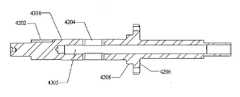
메인 샤프트(105)의 일 실시예가 도 41 내지 도 43에 도시된다. 메인 샤프트(105)는 시프트 로드(112)를 수용하기 위한 내측 보어(4305)를 갖는 긴 몸체이다(도 16 및 도 40 참조). CVT(1500)에서 구현된 바와 같이, 메인 샤프트(105)는 CVT(1500)의 많은 구성 요소를 지지하는 단일 편의 축이다. 단일 편의 축이 메인 샤프트(105)를 위하여 이용되는 실시예에서, 메인 샤프트(105)는 CVT(1500)의 일정 실시예에서 공차의 축적을 감소 또는 제거한다. 더욱이, 다중 편의 축과 비교하여, 단일 편의 메인 샤프트(105)는 CVT(1500)에 더 큰 강성 및 강도를 제공한다.One embodiment of the
메인 샤프트(105)는 또한 시프트 핀(114)을 수용하여 축 방향으로, 즉 메인 샤프트(105)의 종축을 따라서 이동하도록 하는 관통 슬롯(4204)을 포함한다. 슬롯(4204)의 크기는 CVT(1500)의 주어진 적용예에 대한 변속비 범위를 선택적으로 결정하기 위한 시프트 정지부(shift stop)를 제공하도록 선택될 수 있다. 예를 들어, CVT(1500)는 슬롯(4204)의 적절한 치수 및/또는 위치를 선정하여 오버드라이브 범위보다 큰 언더드라이브 범위를 갖도록 또는 그 반대로 구성될 수 있다. 예를 들어, 만일 도 42에 도시된 슬롯(4204)이 CVT(1500)가 가능한 전체 시프트 범위에 대비하도록 가정된다면, 슬롯(4204)보다 짧은 슬롯은 변속비 범위를 감소시킬 것이다. 만일 슬롯(4204)이 도 42의 우측에서 짧아진다면 언더드라이브 범위가 감소될 것이다. 반대로, 슬롯(4204)이 도 42의 좌측에서 짧아진다면 오버드라이브 범위가 감소될 것이다.The
본 실시예에서, 플랜지(4206) 및 견부(4208)는 메인 샤프트(105)에서부터 반지름 방향으로 연장된다. 이미 기술된 바와 같이, 플랜지(4206) 및 견부(4208)는 고정자(1586)를 메인 샤프트(105)에 고정시키는 것을 용이하게 한다. 몇몇 실시예에서, 고정자(1586)의 보어는 견부(4208)가 없어도 가능하도록 메인 샤프트(105)에 장착되는 치수로 형성된다. 다른 실시예에서, 견부(4208) 및/또는 플랜지(4206)는 메인 샤프트(105)로부터의 별도의 부분일 수 있다. 이러한 예에서, 견부(4208) 및/또는 플랜지(4206)는 메인 샤프트(105) 둘레에 동축으로 장착되고, 관련 기술 분야에서 임의의 공지된 수단에 의해 메인 샤프트(105)에 고정된다. 도시된 실시예에서, 메인 샤프트(105)는 플랜지(1610)를 회전식으로 고정시키는 키(1606)를 수용하기 위한 키 안착부(4202)를 포함한다(도 16 참조). 키(1606)는 반달키(woodruff key)일 수 있다. 몇몇 실시예의 메인 샤프트(105)는 제작 가능성, 비용, 강도 및 강성의 관점에서 적절한 금속으로 제작된다. 예를 들어, 메인 샤프트는 강, 마그네슘, 알루미늄 또는 다른 금속 또는 합금으로 제작될 수 있다.In the present embodiment, the
전술된 CVT(1500)의 일 실시예를 갖는 허브(1400)의 작동을 이제 도 39 및 도 40을 특히 참조하여 설명할 것이다. 자유휠(1420)은 (도시되지 않은) 자전거 체인으로부터 토크를 수용한다. 자유휠(1420)이 자유휠 캐리어(1510)에 고정되어 있기 때문에, 자유휠(1420)은 토크를 자유휠 캐리어(1510)에 부가하고, 자유휠 캐리어(1510)는 다음으로 토크를 (도시되지 않은) 키 커플링을 거쳐 입력 샤프트(1505)로 전달한다. 메인 샤프트(105)에 장착된 니들 베어링(4010, 4020) 상에서 주행하는 입력 샤프트(1505)는 토크를 스플라인 보어(2710)와 입력 샤프트(1505)의 스플라인 표면(2720, 3410)을 거쳐 토션 디스크(1525)로 입력한다. 니들 베어링(4010)은 자유휠 캐리어(1510) 및/또는 자유휠(1420) 근처 또는 아래에 배치되는 것이 바람직하다. 이러한 배치는 입력 샤프트(1505)에 적절한 지지를 제공하여 CVT(1400)를 통하여 굽힘 하중으로서 자유휠 캐리어(1510)로부터의 반지름 방향 하중의 전달을 방지한다. 더욱이, 몇몇 실시예에서, 스페이서(4030)가 니들 베어링(4010, 4020) 사이에 구비된다. 스페이서(4030)는, 예를 들어, 테프론으로 제작된다.Operation of the
토션 디스크(1525)가 회전함에 따라, 토션 디스크(1525)에 결합된 로드 캠 디스크(1530)는 이러한 회전을 추종하고, 이어서 경사부(3610)는 롤러(2504)를 작동시킨다. 롤러(2504)는 로드 캠 디스크(1540)의 경사부(3610)를 타고 올라가서 로드 캠 디스크(1530)와 로드 캠 디스크(1540) 사이에 쐐기식으로 고정된다. 롤러(2504)의 쐐기식 고정은 로드 캠 디스크(1530)로부터 로드 캠 디스크(1540)로 토크 및 축력 모두의 전달을 가져온다. 롤러 케이지(1535)는 롤러(2504)를 적절한 정렬 상태로 유지하는 기능을 한다.As the
로드 캠 디스크(1540)가 입력 디스크(1545)에 단단히 결합되기 때문에, 로드 캠 디스크(1540)는 축력 및 토크 모두를 입력 디스크(1545)로 전달하여, 마찰 접촉을 통하여 축력 및 토크를 볼(101)에 부가하게 된다. 입력 디스크(1545)가 로드 캠 디스크(1540)로부터 수용한 토크에 의해 회전함에 따라, 입력 디스크(1545)와 볼(101) 사이의 마찰 접촉은 볼(101)이 축(3702)에 대해 자전하도록 강제한다. 본 실시예에서, 축(3702)은 볼(101)과 함께 그의 종축에 대해 회전하지 못하도록 구속되지만, 축(3702)은 시프트 중에서와 같이 볼(101)의 중심에 대해 선회하거나 경사질 수 있다.Since the
입력 디스크(1545), 출력 디스크(1560) 및 아이들러(1526)는 볼(101)과 마찰 접촉을 한다. 볼(101)이 축(3702)에 대해 자전함에 따라, 볼(101)은 토크를 출력 디스크(1560)에 부가하여, 출력 디스크(1560)를 샤프트(105)에 대해 회전하도록 강제한다. 출력 디스크(1560)가 허브 쉘(138)에 단단히 결합되기 때문에, 출력 디스크(1560)는 출력 토크를 허브 쉘(138)에 부가한다. 허브 쉘(138)은 메인 샤프트(105) 둘레에 동축으로 회전 가능하게 장착된다. 그 다음, 허브 쉘(138)은 출력 토크를 자전거의 휠에 스포크와 같은 공지의 방법을 통하여 전달한다.
도 39 및 도 40을 다시 참조하면, 입력 속도대 출력 속도의 비의 시프트 및 그에 따른 입력 토크대 출력 토크의 비의 시프트는 축(3702)의 각도 시프트를 요구하는 볼(101)의 회전축을 기울임으로써 달성된다. 변속비의 시프트는, 도 3의 시프트 로드(312)의 회전시, 또는 메인 샤프트(105) 내의 시프트 로드(112)의 축 방향 이동을 가동시키는 것을 필요로 한다. 시프트 로드(112)는 연장부(1528)의 보어(1910)를 통하여 시프트 캠(1527)과 접촉하는 핀(114)을 축 방향으로 병진시킨다. 시프트 핀(114)의 축 방향 운동은 시프트 캠(1527)의 대응하는 축 방향 운동을 일으킨다. 시프트 캠(1527)이 (예를 들어, 캠 휠(152)을 통하여) 레그(103)와 결합하기 때문에, 레그(103)는 시프트 캠 프로파일(2110)을 따라 이동하면서 반지름 방향으로 이동한다. 레그(103)가 축(3702)과 연결되어 있기 때문에, 레그(103)는 볼(101)의 중심에 대해 축(3702)을 선회시키는 레버의 역할을 한다. 축(3702)의 이러한 선회는 볼(101)이 회전축을 바꾸도록 하여, 그 결과 변속기 내에서 변속비 시프트를 이루게 된다.Referring again to FIGS. 39 and 40, the shift of the ratio of input speed to output speed and thus the ratio of input torque to output torque tilts the axis of rotation of the
도 44 및 도 45는 입력 디스크(1545)에 작동하는 하나의 로드 캠 디스크(4440)와 출력 디스크(1560)에 작동하는 다른 하나의 로드 캠 디스크(4420)를 포함하는 축력 발생 메커니즘을 갖는 CVT(4400)의 일 실시예를 도시한다. 본 실시예에서, 로드 캠 디스크(4440, 4420)는 로드 캠 디스크(1530, 1540)의 경사부(3610)와 같은 경사부를 포함한다. 본 실시예에서, 입력 디스크(1545) 또는 출력 디스크(1560) 어느 것도 경사부를 갖지 않거나 경사부를 갖는 디스크와 결합되지 않는다. 그러나, 다른 실시예에서, 로드 캠 디스크(4420, 4440)와 함께 작동하도록 입력 디스크(1545) 또는 출력 디스크(1560)의 하나 또는 둘 모두에 경사부를 갖는 디스크를 구비하거나 입력 디스크(1545) 및/또는 출력 디스크(1560)에 경사부를 형성한 디스크를 구비하는 것이 바람직할 수 있다. 몇몇 실시예의 CVT(4400)는 롤러 리테이너(4430)를 더 포함하여 로드 캠 디스크(4420)와 출력 디스크(1560) 사이에 있는 (도시되지 않은) 한 세트의 롤러를 내장하고 정렬한다. 도시된 실시예에서, 롤러 리테이너(4430)는 출력 디스크(1560) 상에서 반지름 방향으로 안내된다. 유사하게, 로드 캠 디스크(4440)와 입력 디스크(1545) 사이에는 롤러 리테이너(4410)가 있다. 이들 실시예에서 참고한 롤러 및 디스크는 이전의 축력 발생 장치를 위한 전술된 바와 같은 임의의 타입 또는 형상일 수 있다. 몇몇 실시예에서, 경사부는 디스크의 표면으로부터 1도, 2도, 3도, 4도, 5도, 6도, 7도, 8도, 9도, 10도, 11도, 12도, 13도, 14도, 15도 또는 그 이상인 각도(또는 이들 사이의 각도)로 또는 이들 중 어느 각도 사이의 임의의 일부 각도로 경사진다.44 and 45 illustrate a CVT having an axial force generating mechanism including one
도 46은 베어링 항력 재순환 효과를 감소시키도록 구성된 입력 샤프트(4605) 및 메인 샤프트(4625)를 갖는 CVT(1600)의 일 실시예를 도시한다. CVT(100)는 니들 롤러 베어링(4620)에 의해 부분적으로 반작용하게 되는 축력을 발생시키는 축력 발생기(165)를 포함한다. 허브 캡(4660)은 니들 롤러 베어링(4620)으로부터의 축력 및 항력 토크에 대해 반작용한다. 다른 실시예에서 니들 롤러 베어링(4620)은 볼 스러스트 베어링으로 교체되고 다른 실시예에서 이러한 볼 스러스트 베어링은 니들 롤러 베어링(4620)의 직경보다 작은 직경을 갖는다.46 illustrates one embodiment of a
본 실시예에서, 메인 샤프트(4625)는, 예를 들어, (몇몇 실시예에서 모두가 일체로 된) 클립일 수 있는 와셔(4615)에 대한 반작용 표면을 제공하는 견부(4650)를 갖는다. 입력 샤프트(4605)에는 베어링(4645)에 대항하여 반작용하는 연장부가 구비된다. 베어링(4645)은 스러스트 베어링일 수 있다. 도시된 바와 같이, 입력 샤프트(4605) 및 (토션 디스크(1525)와 유사한) 구동기 디스크는 단일 편이다. 그러나, 다른 실시예에서, 입력 샤프트(4605)는, 예를 들어, 나사, 키, 또는 다른 체결 수단에 의해 토션 디스크(1525)에 결합될 수 있다. 도시된 실시예에서, 축력의 발생으로부터 일어나는 반력의 일부는 메인 샤프트(4625)에 반작용하게 되어, 베어링 항력 재순환을 감소시킨다. (도시되지 않은) 또 다른 실시예에서, 연장부(1410)는 메인 샤프트(4625) 상에 입력 샤프트(4605)를 또한 지지하는 앵귤러 스러스트 베어링에 대항하여 반작용하게 된다. 이러한 후자의 실시예에서, 견부(4650) 및 와셔(4615)는 요구되지 않는다. 오히려, 메인 샤프트(4625)는 앵귤러 스러스트 베어링을 지지 및 보유하도록 구성될 수 있다.In this embodiment, the
여기에서 기술된 많은 실시예에서, 기술된 많은 요소를 지지하는 베어링의 마찰을 줄이기 위하여 윤활 유체가 사용된다. 더욱이, 몇몇 실시예는 변속기를 통하여 토크를 전달하는 견인 구성 요소에 높은 견인 계수를 제공하는 유체에서 이점을 얻는다. 일정 실시예에서 사용하기 위한 "견인 유체(traction fluid)"라고 하는 이러한 유체는 상업적으로 입수 가능한 Santotrac 50, 아쉬랜드 오일(Ashland oil)의 5CST AF, 루브리졸(Lubrizol)의 OS#155378, 엑손 모빌(Exxon Mobile)의 IVT Fluid #SL-2003B21-A, 그리고 임의의 다른 적절한 윤활제를 포함한다. 몇몇 실시예에서, 토크 전달 구성 요소용 견인 유체는 베어링을 윤활하는 윤활제로부터 분리된다.In many of the embodiments described herein, lubricating fluid is used to reduce the friction of bearings supporting many of the elements described. Moreover, some embodiments benefit from fluids that provide high traction coefficients for traction components that transmit torque through the transmission. Such fluids, referred to as "traction fluids" for use in certain embodiments, are commercially available Santotrac 50, 5CST AF from Ashland oil, OS # 155378 from Lubrizol, Exon IVT Fluid # SL-2003B21-A from Mobil, Exxon Mobile, and any other suitable lubricant. In some embodiments, the traction fluid for the torque transmission component is separated from the lubricant that lubricates the bearing.
전술한 내용은 본 발명의 일정 실시예를 상세히 설명한다. 그러나, 전술한 내용이 본문에서 아무리 상세하더라도, 본 발명은 여러 방식으로 구현될 수 있음은 물론일 것이다. 또한 전술된 바와 같이, 본 발명의 일정한 구성 및 태양을 기술할 때 특정 기술의 사용이 이러한 기술과 관계되는 본 발명의 구성 또는 태양의 임의의 구체적인 특징을 포함하는 것에 한정되도록 본 기술이 여기에서 다시 정의되는 것을 의미하는 것으로 받아들여져서는 안된다는 것에 유의하여야 한다. 따라서, 본 발명의 범위는 첨부된 청구항과 그의 임의의 등가물에 따라 해석되어야 한다.
The foregoing describes in detail certain embodiments of the invention. However, no matter how detailed the foregoing is in the text, it will be appreciated that the invention can be embodied in many ways. Also as described above, the present technology is again here again such that the use of a particular technology in describing certain configurations and aspects of the invention is limited to including any specific features of the configurations or aspects of the invention that relate to such technology. It should be noted that it should not be taken to mean being defined. Accordingly, the scope of the invention should be construed in accordance with the appended claims and any equivalents thereof.
Claims (17)
Translated fromKorean각을 이루며(angularly) 떨어져 배치된 복수의 제1 방사상(radial) 홈(groove)들을 포함하며, 상기 제1 방사상 홈들은 상기 트랙션 롤러 어셈블리의 롤러 축(axle)을 수용하도록 구성되며, 상기 제1 방사상 홈들은 종축으로부터 수직으로 연장된 제1 케이지 디스크와,
각을 이루며(angularly) 떨어져 배치된 복수의 제2 방사상(radial) 홈(groove)들을 포함하며, 상기 제2 방사상 홈들은 상기 롤러 축(axle)을 수용하도록 구성되며, 상기 제2 방사상 홈들은 상기 종축으로부터 수직으로 연장된 제2 케이지 디스크를 포함하며,
상기 제1 및 제2 케이지 디스크는 상기 제1 방사상 홈들이 상기 제2 방사상 홈들에 대해서 각도 방향으로 오프셋(angularly offset)되도록 배치되며,
상기 제1 및 제2 케이지 디스크는 상기 연속 가변 변속기의 종축과 동축상(coaxially)으로 장착되도록 구성되며,
상기 제1 및 제2 케이지 디스크는 각각 상기 연속 가변 변속기의 메인 샤프트와 결합하도록 구성된 보어를 구비하는 케이지.A cage for facilitating support and guidance of a spherical traction roller assembly in a continuously variable transmission,
A plurality of first radial grooves angularly spaced apart, the first radial grooves configured to receive a roller axle of the traction roller assembly; The radial grooves include a first cage disk extending perpendicularly from the longitudinal axis,
A plurality of second radial grooves angularly spaced apart, the second radial grooves configured to receive the roller axle, the second radial grooves being A second cage disk extending vertically from the longitudinal axis,
The first and second cage discs are arranged such that the first radial grooves are angularly offset in the angular direction with respect to the second radial grooves,
The first and second cage discs are configured to be mounted coaxially with a longitudinal axis of the continuous variable transmission,
And the first and second cage discs each having a bore configured to engage a main shaft of the continuously variable transmission.
상기 제1 및 제2 케이지 디스크는 복수의 절단부(cutout)를 구비하는 케이지.The method of claim 1,
Wherein the first and second cage discs have a plurality of cutouts.
상기 제1 케이지 디스크와 제2 케이지 디스크 사이에 위치하도록 배치된 복수의 스페이서를 더 포함하며, 상기 스페이서는 제1 케이지 디스크를 제2 케이지 디스크에 단단하게(rigidly) 결합하는 케이지.The method of claim 1,
And a plurality of spacers disposed to be positioned between the first cage disk and the second cage disk, wherein the spacer rigidly couples the first cage disk to the second cage disk.
상기 제1 케이지 디스크와 제2 케이지 디스크는 각각 대체로 원형인 외주연부(outer periphery)를 구비한 케이지.The method of claim 3,
Wherein the first cage disc and the second cage disc each have a generally circular outer periphery.
상기 제1 및 제2 케이지 디스크는 각각 상기 방사상 홈(groove)들 사이에 형성된 복수의 오목한 표면을 구비한 케이지.The method of claim 1,
Wherein the first and second cage discs each have a plurality of concave surfaces formed between the radial grooves.
상기 케이지의 내면에 형성되며, 종축 주변에 각을 이루며(angularly) 떨어져 배치되며, 상기 종축으로부터 수직으로 연장되며, 상기 트랙션 롤러 어셈블리의 롤러 축(axle)을 수용하도록 구성된 복수의 제1 방사상(radial) 홈(groove)들과,
상기 케이지의 내면에 형성되며, 상기 종축 주변에 각을 이루며(angularly) 떨어져 배치되며, 상기 종축으로부터 수직으로 연장되며, 상기 롤러 축(axle)을 수용하도록 구성된 복수의 제2 방사상 홈들과,
상기 제1 및 제2 방사상 홈들 사이에 배치되도록 구성된 복수의 스페이서들을 포함하며,
상기 제1 방사상 홈들은 상기 제2 방사상 홈과 축 방향으로(axially) 떨어져서 배치되며,
상기 제1 방사상 홈들은 상기 제2 방사상 홈들에 대해서 각도 방향으로 오프셋(angularly offset)되도록 배치되는 케이지.A cage for facilitating support and guidance of a spherical traction roller assembly in a continuously variable transmission,
A plurality of first radials formed on an inner surface of the cage, disposed angularly about a longitudinal axis, extending vertically from the longitudinal axis, and configured to receive a roller axle of the traction roller assembly; ) Grooves,
A plurality of second radial grooves formed in the inner surface of the cage, angularly spaced about the longitudinal axis, extending vertically from the longitudinal axis, the second radial grooves configured to receive the roller axle;
A plurality of spacers configured to be disposed between the first and second radial grooves,
The first radial grooves are disposed axially away from the second radial groove,
And the first radial grooves are arranged to be angularly offset with respect to the second radial grooves.
상기 제1 방사상 홈들의 각각의 홈들의 사이와 상기 제2 방사상 홈들의 각각의 홈들의 사이에 위치하는 복수의 오목한 표면들을 더 구비한 케이지.The method according to claim 6,
And a plurality of concave surfaces located between each of the grooves of the first radial grooves and between each of the grooves of the second radial grooves.
상기 종축 주변에 상기 케이지를 장착하기 용이하도록 구성된 중앙 보어를 더 포함하는 케이지.The method according to claim 6,
And a central bore configured to facilitate mounting of the cage around the longitudinal axis.
상기 제1 방사상 홈들과 제2 방사상 홈들은 각각 제1 케이지 디스크와 제2 케이지 디스크에 형성된 케이지.The method according to claim 6,
And the first radial grooves and the second radial grooves are formed in the first cage disk and the second cage disk, respectively.
상기 제1 케이지 디스크와 제2 케이지 디스크는 각각 대체로 원형인 외주연부를 구비한 케이지.10. The method of claim 9,
Wherein the first cage disc and the second cage disc each have a generally circular outer periphery.
상기 제1 방사상 홈들을 제2 방사상 홈들에 단단하게(rigidly) 결합하는 복수의 스페이서들을 더 포함하는 케이지.The method according to claim 6,
And a plurality of spacers rigidly coupling the first radial grooves to the second radial grooves.
종축으로부터 수직으로 연장되며, 각을 이루며(angularly) 떨어져 배치된 복수의 제1 방사상(radial) 홈(groove)들을 구비한 제1 케이지 디스크와,
상기 종축으로부터 수직으로 연장되며, 각을 이루며(angularly) 떨어져 배치된 복수의 제2 방사상(radial) 홈(groove)들을 구비한 제2 케이지 디스크와,
상기 제1 케이지 디스크와 제2 케이지 디스크 사이에 위치하도록 배치된 복수의 스페이서들을 더 포함하며,
상기 스페이서들은 상기 제1 케이지 디스크를 상기 제2 케이지 디스크에 단단하게(rigidly) 결합하며,
상기 제1 및 제2 케이지 디스크는 상기 제1 방사상 홈들이 상기 제2 방사상 홈들에 대해서 각도 방향으로 오프셋(angularly offset)되도록 배치되며,
상기 제1 및 제2 케이지 디스크는 각각 상기 방사상 홈(groove)들 사이에 형성된 복수의 오목한 표면들을 구비한 케이지.A cage for facilitating support and guidance of a spherical traction roller assembly in a continuously variable transmission,
A first cage disk extending vertically from the longitudinal axis and having a plurality of first radial grooves arranged angularly apart,
A second cage disk extending from the longitudinal axis and having a plurality of second radial grooves arranged angularly apart;
And a plurality of spacers disposed to be positioned between the first cage disk and the second cage disk,
The spacers rigidly couple the first cage disk to the second cage disk,
The first and second cage discs are arranged such that the first radial grooves are angularly offset in the angular direction with respect to the second radial grooves,
Wherein the first and second cage discs each have a plurality of concave surfaces formed between the radial grooves.
상기 제1 및 제2 케이지 디스크는 상기 연속 가변 변속기의 종축과 동축상(coaxially)으로 장착되도록 구성된 케이지.The method of claim 12,
Wherein the first and second cage discs are configured to be mounted coaxially with the longitudinal axis of the continuously variable transmission.
상기 케이지의 내면에 형성되며, 종축 주변에 각을 이루며(angularly) 떨어져 배치되며, 상기 종축으로부터 수직으로 연장된 제1 방사상(radial) 홈(groove)들과,
상기 케이지의 내면에 형성되며, 상기 종축 주변에 각을 이루며(angularly) 떨어져 배치되며, 상기 종축으로부터 수직으로 연장된 제2 방사상 홈들과,
상기 제1 방사상 홈들의 각각의 홈들의 사이와 상기 제2 방사상 홈들의 각각의 홈들의 사이에 위치하는 복수의 오목한 표면들과,
상기 제1과 제2 방사상 홈들 사이에 배치되도록 구성된 복수의 스페이서들을 포함하며,
상기 제1 방사상 홈들은 상기 제2 제1 방사상 홈과 축 방향으로(axially) 떨어져서 배치되며,
상기 제1 방사상 홈들은 상기 제2 방사상 홈들에 대해서 각도 방향으로 오프셋(angularly offset)되도록 배치되는 케이지.A cage for facilitating support and guidance of a spherical traction roller assembly in a continuously variable transmission,
First radial grooves formed on an inner surface of the cage and angularly spaced about a longitudinal axis and extending perpendicularly from the longitudinal axis,
Second radial grooves formed on an inner surface of the cage and angularly spaced about the longitudinal axis and extending vertically from the longitudinal axis,
A plurality of concave surfaces located between each of the grooves of the first radial grooves and between each of the grooves of the second radial grooves;
A plurality of spacers configured to be disposed between the first and second radial grooves,
The first radial grooves are disposed axially away from the second first radial groove,
And the first radial grooves are arranged to be angularly offset with respect to the second radial grooves.
상기 스페이서들은 상기 제1 방사상 홈들을 제2 방사상 홈들에 단단하게(rigidly) 결합하는 케이지.15. The method of claim 14,
And the spacers rigidly couple the first radial grooves to the second radial grooves.
Applications Claiming Priority (3)
| Application Number | Priority Date | Filing Date | Title |
|---|---|---|---|
| US61639904P | 2004-10-05 | 2004-10-05 | |
| US60/616,399 | 2004-10-05 | ||
| PCT/US2005/035164WO2006041718A2 (en) | 2004-10-05 | 2005-10-03 | Continuously variable transmission |
Related Parent Applications (1)
| Application Number | Title | Priority Date | Filing Date |
|---|---|---|---|
| KR1020077010267ADivisionKR101276080B1 (en) | 2004-10-05 | 2005-10-03 | Continuously variable transmission |
Publications (2)
| Publication Number | Publication Date |
|---|---|
| KR20120104645A KR20120104645A (en) | 2012-09-21 |
| KR101276082B1true KR101276082B1 (en) | 2013-06-18 |
Family
ID=36148799
Family Applications (3)
| Application Number | Title | Priority Date | Filing Date |
|---|---|---|---|
| KR1020127023652AExpired - LifetimeKR101276082B1 (en) | 2004-10-05 | 2005-10-03 | Continuously variable transmission |
| KR1020077010267AExpired - LifetimeKR101276080B1 (en) | 2004-10-05 | 2005-10-03 | Continuously variable transmission |
| KR1020127016632AWithdrawnKR20120088869A (en) | 2004-10-05 | 2005-10-03 | Continuously variable transmission |
Family Applications After (2)
| Application Number | Title | Priority Date | Filing Date |
|---|---|---|---|
| KR1020077010267AExpired - LifetimeKR101276080B1 (en) | 2004-10-05 | 2005-10-03 | Continuously variable transmission |
| KR1020127016632AWithdrawnKR20120088869A (en) | 2004-10-05 | 2005-10-03 | Continuously variable transmission |
Country Status (14)
| Country | Link |
|---|---|
| US (20) | US7762919B2 (en) |
| EP (2) | EP1815165B1 (en) |
| JP (3) | JP4974896B2 (en) |
| KR (3) | KR101276082B1 (en) |
| CN (1) | CN101166922B (en) |
| AT (1) | ATE550573T1 (en) |
| AU (1) | AU2005294611B2 (en) |
| BR (1) | BRPI0516562A (en) |
| CA (2) | CA2582562C (en) |
| DK (1) | DK1815165T3 (en) |
| MX (3) | MX2007003828A (en) |
| PL (1) | PL1815165T3 (en) |
| TW (1) | TWI309700B (en) |
| WO (1) | WO2006041718A2 (en) |
Families Citing this family (118)
| Publication number | Priority date | Publication date | Assignee | Title |
|---|---|---|---|---|
| US6551210B2 (en)* | 2000-10-24 | 2003-04-22 | Motion Technologies, Llc. | Continuously variable transmission |
| KR100854795B1 (en)* | 2001-04-26 | 2008-08-27 | 모션 테크놀로지즈 엘엘씨 | Device for speed ratio adjustment of roller traction transmission and continuous variable transmission |
| US7011600B2 (en) | 2003-02-28 | 2006-03-14 | Fallbrook Technologies Inc. | Continuously variable transmission |
| US7166052B2 (en) | 2003-08-11 | 2007-01-23 | Fallbrook Technologies Inc. | Continuously variable planetary gear set |
| EP1774199B1 (en)* | 2004-07-21 | 2013-06-12 | Fallbrook Intellectual Property Company LLC | Rolling traction planetary drive |
| WO2006041718A2 (en)* | 2004-10-05 | 2006-04-20 | Fallbrook Technologies, Inc. | Continuously variable transmission |
| WO2007044128A2 (en) | 2005-08-22 | 2007-04-19 | Viryd Technologies Inc. | Fluid energy converter |
| US7670243B2 (en)* | 2005-08-24 | 2010-03-02 | Fallbrook Technologies, Inc. | Continuously variable transmission |
| WO2007070167A2 (en) | 2005-10-28 | 2007-06-21 | Fallbrook Technologies Inc. | Electromotive drives |
| PL1954959T3 (en) | 2005-11-22 | 2013-10-31 | Fallbrook Ip Co Llc | Continuously variable transmission |
| CN102221073B (en)* | 2005-12-09 | 2013-03-27 | 福博科技术公司 | Continuously variable transmission |
| EP1811202A1 (en)* | 2005-12-30 | 2007-07-25 | Fallbrook Technologies, Inc. | A continuously variable gear transmission |
| US7882762B2 (en) | 2006-01-30 | 2011-02-08 | Fallbrook Technologies Inc. | System for manipulating a continuously variable transmission |
| WO2007106874A2 (en) | 2006-03-14 | 2007-09-20 | Autocraft Industries, Inc. | Improved wheelchair |
| US20080070729A1 (en)* | 2006-05-11 | 2008-03-20 | Fallbrook Technologies Inc. | Continuously variable drivetrain |
| CN102269055B (en) | 2006-06-26 | 2013-08-28 | 福博科技术公司 | Continuously variable transmission |
| PL2089642T3 (en) | 2006-11-08 | 2013-09-30 | Fallbrook Ip Co Llc | Clamping force generator |
| EP2125469A2 (en) | 2007-02-01 | 2009-12-02 | Fallbrook Technologies Inc. | System and methods for control of transmission and/or prime mover |
| GB0702490D0 (en)* | 2007-02-09 | 2007-03-21 | Torotrak Dev Ltd | CVT control system |
| US20100093479A1 (en) | 2007-02-12 | 2010-04-15 | Fallbrook Technologies Inc. | Continuously variable transmissions and methods therefor |
| TWI461615B (en) | 2007-02-16 | 2014-11-21 | Fallbrook Ip Co Llc | Infinitely variable transmissions, continuously variable transmissions, methods, assemblies, subassemblies, and components therefor |
| EP2142826B1 (en) | 2007-04-24 | 2015-10-28 | Fallbrook Intellectual Property Company LLC | Electric traction drives |
| US8641577B2 (en) | 2007-06-11 | 2014-02-04 | Fallbrook Intellectual Property Company Llc | Continuously variable transmission |
| CN103697120B (en) | 2007-07-05 | 2017-04-12 | 福博科技术公司 | Continuously variable transmission |
| US7887032B2 (en)* | 2007-11-07 | 2011-02-15 | Fallbrook Technologies Inc. | Self-centering control rod |
| CN103939602B (en) | 2007-11-16 | 2016-12-07 | 福博科知识产权有限责任公司 | Controllers for variable speed drives |
| US7878935B2 (en)* | 2007-11-26 | 2011-02-01 | Derek Lahr | Continuously variable transmission with external cam |
| US8321097B2 (en) | 2007-12-21 | 2012-11-27 | Fallbrook Intellectual Property Company Llc | Automatic transmissions and methods therefor |
| US8313405B2 (en) | 2008-02-29 | 2012-11-20 | Fallbrook Intellectual Property Company Llc | Continuously and/or infinitely variable transmissions and methods therefor |
| US8317651B2 (en) | 2008-05-07 | 2012-11-27 | Fallbrook Intellectual Property Company Llc | Assemblies and methods for clamping force generation |
| CN102112778B (en) | 2008-06-06 | 2013-10-16 | 福博科技术公司 | Infinitely variable transmission, continuously variable transmission, methods, assemblies, subassemblies and components therefor |
| CN103438165B (en)* | 2008-06-06 | 2016-08-17 | 福博科技术公司 | Unlimited formula buncher, buncher, for its method, assembly, sub-component and parts |
| EP2304272B1 (en) | 2008-06-23 | 2017-03-08 | Fallbrook Intellectual Property Company LLC | Continuously variable transmission |
| CN104019201B (en)* | 2008-06-23 | 2017-07-28 | 福博科知识产权有限责任公司 | Buncher |
| CA2732668C (en) | 2008-08-05 | 2017-11-14 | Fallbrook Technologies Inc. | Methods for control of transmission and prime mover |
| US8469856B2 (en)* | 2008-08-26 | 2013-06-25 | Fallbrook Intellectual Property Company Llc | Continuously variable transmission |
| US8167759B2 (en) | 2008-10-14 | 2012-05-01 | Fallbrook Technologies Inc. | Continuously variable transmission |
| CN104019200B (en)* | 2008-10-14 | 2017-07-14 | 福博科知识产权有限责任公司 | Buncher |
| US9464701B2 (en)* | 2009-01-22 | 2016-10-11 | Orbital Traction, Ltd. | Fluid movement systems including a continuously variable transmission |
| ES2439647T3 (en) | 2009-04-16 | 2014-01-24 | Fallbrook Intellectual Property Company Llc | Stator set and speed change mechanism for a continuously variable transmission |
| US20120025644A1 (en)* | 2009-04-21 | 2012-02-02 | Toyota Jidosha Kabushiki Kaisha | Electric motor having speed change function |
| US9151269B2 (en) | 2009-07-20 | 2015-10-06 | Differential Dynamics Corporation | Run-of-the-river or ocean current turbine |
| US8512195B2 (en) | 2010-03-03 | 2013-08-20 | Fallbrook Intellectual Property Company Llc | Infinitely variable transmissions, continuously variable transmissions, methods, assemblies, subassemblies, and components therefor |
| DE112010005401B8 (en)* | 2010-03-18 | 2014-11-13 | Toyota Jidosha Kabushiki Kaisha | Continuously variable transmission |
| GB2488506A (en) | 2010-04-15 | 2012-09-05 | Orbital Traction Ltd A Texas Ltd Partnership | Continuously variable transmission with non-linear end clamping force |
| US9631563B2 (en) | 2010-06-30 | 2017-04-25 | Orbital Traction, Ltd | Torque pulse dampener |
| US9912209B2 (en) | 2010-07-20 | 2018-03-06 | Differential Dynamics Corporation | Renewable energy marine hydrokinetic or wind turbine |
| US9476401B2 (en) | 2010-07-20 | 2016-10-25 | Differential Dynamics Corporation | Marine hydrokinetic turbine |
| US8888643B2 (en) | 2010-11-10 | 2014-11-18 | Fallbrook Intellectual Property Company Llc | Continuously variable transmission |
| AU2012240435B2 (en) | 2011-04-04 | 2016-04-28 | Fallbrook Intellectual Property Company Llc | Auxiliary power unit having a continuously variable transmission |
| US9707138B2 (en) | 2011-07-27 | 2017-07-18 | The Board Of Trustees Of The University Of Illinois | Gear-shifting system for manually propelled wheelchairs |
| US8956262B2 (en) | 2011-09-22 | 2015-02-17 | Toyota Jidosha Kabushiki Kaisha | Continuously variable transmission |
| GB201120227D0 (en)* | 2011-11-23 | 2012-01-04 | Crompton Technology Group Ltd | Composite material component |
| US8613235B2 (en)* | 2011-12-02 | 2013-12-24 | Carlos Raul Espinosa-Montalvo | Continuously variable transmission |
| KR101251617B1 (en)* | 2011-12-21 | 2013-04-08 | 남부대학교산학협력단 | Stepless transmission type spherical frictional |
| GB201200357D0 (en)* | 2012-01-10 | 2012-02-22 | Torotrak Dev Ltd | Variator |
| US9090312B2 (en) | 2012-01-12 | 2015-07-28 | Shimano Inc. | Continuously variable bicycle transmission |
| US9347532B2 (en) | 2012-01-19 | 2016-05-24 | Dana Limited | Tilting ball variator continuously variable transmission torque vectoring device |
| CN104302949B (en) | 2012-01-23 | 2017-05-03 | 福博科知识产权有限责任公司 | Infinitely variable continuously variable transmission, continuously variable continuously variable transmission, method, assembly, subassembly, and parts thereof |
| CN104204615B (en) | 2012-02-15 | 2017-10-24 | 德纳有限公司 | Transmission device and the power train with tilt ball speed changer infinitely variable speed transmission |
| WO2013125041A1 (en)* | 2012-02-24 | 2013-08-29 | トヨタ自動車株式会社 | Continuously variable transmission |
| JP5590265B2 (en)* | 2012-03-09 | 2014-09-17 | トヨタ自動車株式会社 | Continuously variable transmission |
| US8939866B2 (en)* | 2012-03-15 | 2015-01-27 | Hamilton Sundstrand Corporation | Toroidal traction drive |
| EP2893219A4 (en) | 2012-09-06 | 2016-12-28 | Dana Ltd | Transmission having a continuously or infinitely variable variator drive |
| WO2014039438A2 (en)* | 2012-09-06 | 2014-03-13 | Dana Limited | Cvt variator ball and method of construction thereof |
| WO2014039713A1 (en) | 2012-09-07 | 2014-03-13 | Dana Limited | Ivt based on a ball type cvp including powersplit paths |
| WO2014039708A1 (en) | 2012-09-07 | 2014-03-13 | Dana Limited | Ball type cvt including a direct drive mode |
| US9689477B2 (en) | 2012-09-07 | 2017-06-27 | Dana Limited | Ball type continuously variable transmission/infinitely variable transmission |
| CN104768787A (en) | 2012-09-07 | 2015-07-08 | 德纳有限公司 | Ball type CVT with powersplit paths |
| US9599204B2 (en) | 2012-09-07 | 2017-03-21 | Dana Limited | Ball type CVT with output coupled powerpaths |
| JP6320386B2 (en) | 2012-09-07 | 2018-05-09 | デーナ リミテッド | Ball type CVT / IVT including planetary gear set |
| JP5590098B2 (en) | 2012-10-31 | 2014-09-17 | トヨタ自動車株式会社 | Continuously variable transmission |
| US10030748B2 (en) | 2012-11-17 | 2018-07-24 | Dana Limited | Continuously variable transmission |
| CN103887263B (en)* | 2012-12-21 | 2016-12-28 | 碁鼎科技秦皇岛有限公司 | Encapsulating structure and preparation method thereof |
| US9005068B2 (en)* | 2012-12-21 | 2015-04-14 | Shimano Inc. | Continuously variable bicycle transmission mechanism and bicycle hub |
| US9429217B2 (en) | 2013-01-28 | 2016-08-30 | Robert Hornblower Meyer | Continuously variable drive mechanism |
| WO2014124063A1 (en) | 2013-02-08 | 2014-08-14 | Microsoft Corporation | Pervasive service providing device-specific updates |
| US20140235385A1 (en)* | 2013-02-21 | 2014-08-21 | Armin Sebastian Tay | Cone with member cvt for which belt tension can be reduced |
| US9551404B2 (en) | 2013-03-14 | 2017-01-24 | Dana Limited | Continuously variable transmission and an infinitely variable transmission variator drive |
| CN105121905A (en) | 2013-03-14 | 2015-12-02 | 德纳有限公司 | Ball type continuously variable transmission |
| US8814739B1 (en) | 2013-03-14 | 2014-08-26 | Team Industries, Inc. | Continuously variable transmission with an axial sun-idler controller |
| US8827856B1 (en) | 2013-03-14 | 2014-09-09 | Team Industries, Inc. | Infinitely variable transmission with an IVT stator controlling assembly |
| US9322461B2 (en) | 2013-03-14 | 2016-04-26 | Team Industries, Inc. | Continuously variable transmission with input/output planetary ratio assembly |
| US9133918B2 (en) | 2013-03-14 | 2015-09-15 | Team Industries, Inc. | Continuously variable transmission with differential controlling assemblies |
| US9057439B2 (en) | 2013-03-14 | 2015-06-16 | Team Industries, Inc. | Infinitely variable transmission with IVT traction ring controlling assemblies |
| JP5621872B2 (en) | 2013-04-04 | 2014-11-12 | トヨタ自動車株式会社 | Continuously variable transmission |
| KR102433297B1 (en) | 2013-04-19 | 2022-08-16 | 폴브룩 인텔렉츄얼 프로퍼티 컴퍼니 엘엘씨 | Continuously variable transmission |
| EP3004686B1 (en) | 2013-06-06 | 2018-08-08 | Dana Limited | 3-mode front wheel drive and rear wheel drive continuously variable planetary transmission |
| JP2015017664A (en)* | 2013-07-11 | 2015-01-29 | 日本精工株式会社 | Electric vehicle drive |
| JP2015075185A (en)* | 2013-10-10 | 2015-04-20 | 日本精工株式会社 | Single cavity type toroidal type continuously variable transmission |
| WO2015073948A2 (en) | 2013-11-18 | 2015-05-21 | Dana Limited | Torque peak detection and control mechanism for cvp |
| US10030751B2 (en) | 2013-11-18 | 2018-07-24 | Dana Limited | Infinite variable transmission with planetary gear set |
| JP6003943B2 (en)* | 2014-04-28 | 2016-10-05 | トヨタ自動車株式会社 | Hybrid vehicle and control method of hybrid vehicle |
| ES2554181B1 (en)* | 2014-06-12 | 2016-06-09 | José Antonio CARAMÉS JIMÉNEZ | Continuously Variable Automatic Transmission |
| CN106536987A (en) | 2014-06-17 | 2017-03-22 | 德纳有限公司 | Off-highway continuously variable planetary-based multimore transmission including infinite variable transmission and direct continuously variable tranmission |
| JP6408327B2 (en)* | 2014-09-30 | 2018-10-17 | 日本電産シンポ株式会社 | Friction type continuously variable transmission |
| JP6241427B2 (en)* | 2015-01-27 | 2017-12-06 | トヨタ自動車株式会社 | Hybrid vehicle |
| US9719581B2 (en)* | 2015-03-19 | 2017-08-01 | Allison Transmission, Inc. | Variator stator functional and manufacturing improvements |
| WO2016164026A1 (en)* | 2015-04-09 | 2016-10-13 | Allison Transmission Inc. | Continuously variable planetary transmission |
| US11078812B2 (en) | 2015-07-13 | 2021-08-03 | Borgwarner Inc. | Continuously variable friction drive phaser |
| US10035511B2 (en)* | 2015-07-27 | 2018-07-31 | Cummins Inc. | Method and system for controlling operation of an engine powered device having cyclical duty cycles |
| CN108138929A (en)* | 2015-08-11 | 2018-06-08 | 德纳有限公司 | Hydraulic speed ratio control method for vehicle having ball-shift continuously variable transmission |
| US10030594B2 (en) | 2015-09-18 | 2018-07-24 | Dana Limited | Abuse mode torque limiting control method for a ball-type continuously variable transmission |
| US10047861B2 (en) | 2016-01-15 | 2018-08-14 | Fallbrook Intellectual Property Company Llc | Systems and methods for controlling rollback in continuously variable transmissions |
| KR102364407B1 (en) | 2016-03-18 | 2022-02-16 | 폴브룩 인텔렉츄얼 프로퍼티 컴퍼니 엘엘씨 | continuously variable transmission system and method |
| US10023266B2 (en) | 2016-05-11 | 2018-07-17 | Fallbrook Intellectual Property Company Llc | Systems and methods for automatic configuration and automatic calibration of continuously variable transmissions and bicycles having continuously variable transmissions |
| US10253881B2 (en)* | 2016-05-20 | 2019-04-09 | Fallbrook Intellectual Property Company Llc | Systems and methods for axial force generation |
| JP6773297B2 (en) | 2016-10-14 | 2020-10-21 | 日本電産シンポ株式会社 | Continuously variable transmission and bicycle |
| US10253857B2 (en) | 2017-01-31 | 2019-04-09 | Dana Heavy Vehicle Systems Group, Llc | Multi-speed electric transaxle unit with co-axial shafts |
| TWI868953B (en)* | 2017-05-30 | 2025-01-01 | 日商島野股份有限公司 | Bicycle rear hub assembly and sprocket support body |
| CN107559398A (en)* | 2017-07-26 | 2018-01-09 | 江苏创斯达科技有限公司 | A kind of drive mechanism |
| US10400882B2 (en) | 2017-10-18 | 2019-09-03 | Deere & Company | Product and method of assembling multiple components using a press fit |
| US11215268B2 (en) | 2018-11-06 | 2022-01-04 | Fallbrook Intellectual Property Company Llc | Continuously variable transmissions, synchronous shifting, twin countershafts and methods for control of same |
| MX2021003494A (en) | 2018-12-27 | 2021-06-18 | Differential Dynamics Corp | Scalable and efficient mechanical speed converter-controlled wind and hydrokinetic turbines. |
| WO2020176392A1 (en) | 2019-02-26 | 2020-09-03 | Fallbrook Intellectual Property Company Llc | Reversible variable drives and systems and methods for control in forward and reverse directions |
| US11808326B2 (en)* | 2019-09-04 | 2023-11-07 | Aidan McAnulla | Infinitely variable multi-epicyclic friction transmission system for electric motor |
| CN112621244B (en)* | 2020-12-22 | 2021-12-10 | 浙江高金电子科技有限责任公司 | Cutting, chamfering and welding integrated machine for machining automobile air conditioner pipe fitting |
| TWI854587B (en)* | 2023-04-10 | 2024-09-01 | 龍宸有限公司 | Structure of pulley set for motorcycle |
Citations (2)
| Publication number | Priority date | Publication date | Assignee | Title |
|---|---|---|---|---|
| US3800607A (en)* | 1971-02-18 | 1974-04-02 | A Zurcher | Friction ring drive with intermediate disks |
| CA2401474A1 (en)* | 2002-09-05 | 2004-03-05 | Ecole De Technologie Superieure | Drive roller control for toric-drive transmission |
Family Cites Families (678)
| Publication number | Priority date | Publication date | Assignee | Title |
|---|---|---|---|---|
| USRE22761E (en) | 1946-05-28 | Transmission | ||
| GB592320A (en) | 1945-03-13 | 1947-09-15 | Frederick Whigham Mcconnel | Improvements in or relating to variable speed-gears |
| US1121210A (en) | 1914-12-15 | Fried Krupp Germaniawerft Ag | Submarine boat. | |
| US2675713A (en) | 1954-04-20 | Protective mechanism for variable | ||
| US719595A (en) | 1901-07-06 | 1903-02-03 | Jacob B Huss | Bicycle driving mechanism. |
| US1207985A (en) | 1914-08-17 | 1916-12-12 | Charles I Null | Antifriction-hanger. |
| US1175677A (en) | 1914-10-24 | 1916-03-14 | Roderick Mcclure | Power-transmitting device. |
| US1234567A (en)* | 1915-09-14 | 1917-07-24 | Edward J Quigley | Soft collar. |
| US1380006A (en) | 1917-08-04 | 1921-05-31 | Hamilton Beach Mfg Co | Variable-speed transmission |
| JP3223241B2 (en)* | 1997-03-17 | 2001-10-29 | 本田技研工業株式会社 | Belt type continuously variable transmission |
| US1390971A (en)* | 1921-01-24 | 1921-09-13 | Samain Pierre | Gearing |
| US1579359A (en)* | 1921-10-06 | 1926-04-06 | Charles B Rose | Clutch |
| US1588222A (en)* | 1923-08-17 | 1926-06-08 | Jr Henry D Olier | Lighting device |
| US1558222A (en) | 1924-01-14 | 1925-10-20 | Beetow Albert | Backlash take-up for gears |
| US1629902A (en) | 1924-08-07 | 1927-05-24 | Arter Jakob | Power-transmitting device |
| CH118064A (en) | 1924-08-07 | 1926-12-16 | Jakob Arter | Friction change transmission. |
| US1686446A (en) | 1926-04-15 | 1928-10-02 | John A Gilman | Planetary transmission mechanism |
| FR620375A (en) | 1926-06-24 | 1927-04-21 | Automatic pressure device for friction plates | |
| US1774254A (en) | 1927-06-28 | 1930-08-26 | John F Daukus | Clutch mechanism |
| US1692902A (en) | 1927-09-01 | 1928-11-27 | James T Moltrup | Die and method of drawing shapes |
| US1903228A (en) | 1927-10-21 | 1933-03-28 | Gen Motors Corp | Frictional gearing |
| DE498701C (en) | 1927-11-18 | 1930-05-31 | Jakob Arter | Friction ball change gear |
| US1865102A (en)* | 1929-05-07 | 1932-06-28 | Frank A Hayes | Variable speed transmission mechanism |
| US1793571A (en)* | 1929-12-14 | 1931-02-24 | Frank O Vaughn | Variable-speed drive |
| US1847027A (en)* | 1930-02-19 | 1932-02-23 | Thomsen Thomas Peter | Change-speed gear |
| US1978439A (en) | 1930-04-01 | 1934-10-30 | John S Sharpe | Variable transmission |
| US1850189A (en) | 1930-07-16 | 1932-03-22 | Carl W Weiss | Transmission device |
| GB391448A (en) | 1930-08-02 | 1933-04-27 | Frank Anderson Hayes | Improvements in or relating to friction transmission |
| US1937234A (en)* | 1931-04-28 | 1933-11-28 | Raymond P Lansing | Driving mechanism |
| US1858696A (en) | 1931-07-08 | 1932-05-17 | Carl W Weiss | Transmission |
| US2131158A (en) | 1932-02-03 | 1938-09-27 | Gen Motors Corp | Continuously variable transmission |
| US2086491A (en) | 1932-04-11 | 1937-07-06 | Adiel Y Dodge | Variable speed transmission |
| US2123008A (en)* | 1932-06-18 | 1938-07-05 | Frank A Hayes | Power transmission mechanism |
| US2109845A (en) | 1932-07-23 | 1938-03-01 | Erban Operating Corp | Power transmission mechanism |
| US2097631A (en)* | 1932-12-09 | 1937-11-02 | Erban Operating Corp | Power transmission mechanism |
| US1965102A (en)* | 1933-01-18 | 1934-07-03 | Carolyn M Jerome | Air heating apparatus |
| US2196064A (en) | 1933-02-04 | 1940-04-02 | Erban Patents Corp | Driving energy consumer |
| US2060884A (en) | 1933-09-19 | 1936-11-17 | Erban Operating Corp | Power transmission mechanism |
| US2112763A (en) | 1933-12-28 | 1938-03-29 | Cloudsley John Leslie | Variable speed power transmission mechanism |
| US2030203A (en)* | 1934-05-31 | 1936-02-11 | Gen Motors Corp | Torque loading lash adjusting device for friction roller transmissions |
| US2134225A (en) | 1935-03-13 | 1938-10-25 | Christiansen Ejnar | Variable speed friction gear |
| US2152796A (en) | 1935-03-13 | 1939-04-04 | Erban Patents Corp | Variable speed transmission |
| US2100629A (en)* | 1936-07-18 | 1937-11-30 | Chilton Roland | Transmission |
| US2209254A (en) | 1938-07-29 | 1940-07-23 | Yrjo A Ahnger | Friction transmission device |
| US2259933A (en) | 1939-02-20 | 1941-10-21 | John O Holloway | Clutch coupling for motor vehicles |
| US2325502A (en)* | 1940-03-08 | 1943-07-27 | Georges Auguste Felix | Speed varying device |
| US2269434A (en) | 1940-11-18 | 1942-01-13 | Cuyler W Brooks | Automatic transmission mechanism |
| US2595367A (en) | 1943-11-09 | 1952-05-06 | Picanol Jaime | Toroidal variable-speed gear drive |
| US2480968A (en) | 1944-08-30 | 1949-09-06 | Ronai Ernest | Variable transmission means |
| US2469653A (en) | 1945-02-01 | 1949-05-10 | Kopp Jean | Stepless variable change-speed gear with roller bodies |
| US2480988A (en)* | 1945-02-06 | 1949-09-06 | Albert E Walton | Window sash lock |
| US2461258A (en) | 1946-06-06 | 1949-02-08 | Cuyler W Brooks | Automatic transmission mechanism |
| US2596538A (en) | 1946-07-24 | 1952-05-13 | Allen A Dicke | Power transmission |
| US2553465A (en) | 1946-11-30 | 1951-05-15 | Monge Jean Raymond Barthelemy | Manual or power-operated planetary transmission |
| NL82920C (en) | 1948-04-17 | |||
| US2586725A (en) | 1950-02-08 | 1952-02-19 | Roller Gear Corp | Variable-speed transmission |
| US2696888A (en) | 1951-05-26 | 1954-12-14 | Curtiss Wright Corp | Propeller having variable ratio transmission for changing its pitch |
| US2716357A (en) | 1952-07-07 | 1955-08-30 | Rennerfelt Sven Bernhard | Continuously variable speed gears |
| US2730904A (en) | 1952-07-14 | 1956-01-17 | Rennerfelt Sven Bernhard | Continuously variable speed gears |
| US2746614A (en)* | 1952-07-18 | 1956-05-22 | Paxton Mitchell Company | Safety uncoupling rigging for locomotive draft gear |
| US2748614A (en) | 1953-06-23 | 1956-06-05 | Zenas V Weisel | Variable speed transmission |
| US2901924A (en) | 1954-08-05 | 1959-09-01 | New Prod Corp | Accessory drive |
| US2873911A (en) | 1955-05-26 | 1959-02-17 | Librascope Inc | Mechanical integrating apparatus |
| US2868038A (en) | 1955-05-26 | 1959-01-13 | Liquid Controls Corp | Infinitely variable planetary transmission |
| US2913932A (en) | 1955-10-04 | 1959-11-24 | Mcculloch Motors Corp | Variable speed planetary type drive |
| US2874592A (en) | 1955-11-07 | 1959-02-24 | Mcculloch Motors Corp | Self-controlled variable speed planetary type drive |
| US2871714A (en)* | 1956-01-30 | 1959-02-03 | Zenas V Weisel | Automotive transmission |
| US2959063A (en) | 1956-09-11 | 1960-11-08 | Perbury Engineering Ltd | Infinitely variable change speed gears |
| US2891213A (en) | 1956-10-30 | 1959-06-16 | Electric Control Corp | Constant frequency variable input speed alternator apparatuses |
| US2950149A (en) | 1957-01-29 | 1960-08-23 | John B Thomson | Relatively reciprocable shaft and bearing |
| US2931235A (en) | 1957-11-12 | 1960-04-05 | George Cohen 600 Group Ltd | Variable speed friction drive transmissions |
| US2931234A (en) | 1957-11-12 | 1960-04-05 | George Cohen 600 Group Ltd | Variable speed friction drive trans-mission units |
| US2883883A (en)* | 1957-11-13 | 1959-04-28 | Curtiss Wright Corp | Variable speed transmission |
| US2964959A (en) | 1957-12-06 | 1960-12-20 | Gen Motors Corp | Accessory drive transmission |
| DE1171692B (en) | 1958-01-09 | 1964-06-04 | Fabrications Unicum Soc D | Friction gear with several flat friction discs |
| BE574149A (en) | 1958-01-09 | 1959-04-16 | Fabrications Unicum Soc D | Pressure device of friction speed variators |
| US3048056A (en) | 1958-04-10 | 1962-08-07 | Gen Motors Corp | Drive system |
| US3035460A (en) | 1958-12-02 | 1962-05-22 | Guichard Louis | Automatic infinitely variablespeed drive |
| US2959070A (en) | 1959-01-09 | 1960-11-08 | Borg Warner | Accessory drive |
| US2959972A (en) | 1959-02-11 | 1960-11-15 | Avco Mfg Corp | Single ball joint roller support for toroidal variable ratio transmissions |
| US3051020A (en)* | 1959-02-16 | 1962-08-28 | Thornton Axle Inc | Locking differential with pressure relief device |
| US3008061A (en) | 1959-04-21 | 1961-11-07 | Barden Corp | Slow speed motor |
| US2949800A (en)* | 1959-05-11 | 1960-08-23 | Neuschotz Robert | Tool for installing threaded elements |
| US3248960A (en) | 1959-11-13 | 1966-05-03 | Roller Gear Ltd | Variable speed drive transmission |
| DE1178259B (en) | 1959-12-03 | 1964-09-17 | Motoren Werke Mannheim Ag | Main and secondary connecting rod for V machines |
| US3204476A (en) | 1960-04-05 | 1965-09-07 | William S Rouverol | Variable speed transmission |
| US3237468A (en) | 1960-05-13 | 1966-03-01 | Roller Gear Ltd | Variable speed drive transmission |
| US3246531A (en) | 1960-11-04 | 1966-04-19 | Kashihara Manabu | Infinitely variable speed change gear |
| DE1217166B (en) | 1960-11-04 | 1966-05-18 | Manabu Kashihara | Ball friction gear with swiveling balls |
| BE629125A (en) | 1961-03-08 | |||
| US3229538A (en) | 1961-09-25 | 1966-01-18 | Roller Gear Ltd | Variable speed drive transmission |
| US3154957A (en) | 1961-10-16 | 1964-11-03 | Kashihara Manabu | Infinitely variable speed change gear utilizing a ball |
| US3086704A (en) | 1961-11-24 | 1963-04-23 | Ryan Aeronautical Co | Cosine-secant multiplier |
| US3087248A (en)* | 1962-09-10 | 1963-04-30 | Clary Corp | Strip measuring and marking apparatus |
| CH398236A (en) | 1962-09-20 | 1965-08-31 | Yamamoto Sota | Friction stepless speed variator |
| US3216283A (en) | 1963-03-04 | 1965-11-09 | Ford Motor Co | Variable speed torque transmitting means |
| US3283614A (en) | 1963-04-10 | 1966-11-08 | Gen Motors Corp | Friction drive mechanism |
| US3163050A (en) | 1963-06-19 | 1964-12-29 | Excelermatic | Toroidal transmission bearing means |
| US3211364A (en)* | 1963-10-30 | 1965-10-12 | Lau Blower Co | Blower wheel |
| US3184983A (en)* | 1963-10-30 | 1965-05-25 | Excelermatic | Toroidal transmission mechanism with torque loading cam means |
| FR1376401A (en)* | 1963-12-05 | 1964-10-23 | Fabrications Unicum Soc D | Improvements to the adjustment device of friction speed variators in particular |
| US3258981A (en)* | 1963-12-30 | 1966-07-05 | Ford Motor Co | Infinitely variable speed friction drive |
| JPS441098Y1 (en) | 1964-12-24 | 1969-01-17 | ||
| JPS422843Y1 (en) | 1965-01-18 | 1967-02-20 | ||
| US3273468A (en) | 1965-01-26 | 1966-09-20 | Fawick Corp | Hydraulic system with regenerative position |
| JPS422844Y1 (en) | 1965-02-06 | 1967-02-20 | ||
| JPS413126Y1 (en) | 1965-08-04 | 1966-02-23 | ||
| US3340895A (en) | 1965-08-27 | 1967-09-12 | Sanders Associates Inc | Modular pressure regulating and transfer valve |
| GB1119988A (en) | 1965-10-14 | 1968-07-17 | Nat Res Dev | Transmission system for interconnecting two rotary machines |
| US3464281A (en) | 1965-10-27 | 1969-09-02 | Hiroshi Azuma | Friction-type automatic variable speed means |
| GB1132473A (en) | 1965-11-15 | 1968-11-06 | James Robert Young | Variable ratio friction transmission and control system therefor |
| US3280646A (en) | 1966-02-02 | 1966-10-25 | Ford Motor Co | Control system for an infinitely variable speed friction drive |
| GB1135141A (en) | 1966-07-04 | 1968-11-27 | Self Changing Gears Ltd | Improved auxiliary overdrive gear |
| JPS47448B1 (en) | 1966-07-08 | 1972-01-07 | ||
| US3430504A (en) | 1966-08-29 | 1969-03-04 | Gen Motors Corp | Transmission |
| GB1195205A (en) | 1966-09-12 | 1970-06-17 | Nat Res Dev | Improvements in or relating to Toroidal Race Transmission Units. |
| SE316664B (en) | 1966-11-30 | 1969-10-27 | B Gustavsson | |
| US3407687A (en) | 1967-03-27 | 1968-10-29 | Hayashi Tadashi | Variable ratio power transmission device |
| JPS47962Y1 (en) | 1967-05-09 | 1972-01-14 | ||
| US3477315A (en) | 1967-12-18 | 1969-11-11 | Elmer Fred Macks | Dynamoelectric device with speed change mechanism |
| US3464291A (en)* | 1967-12-22 | 1969-09-02 | Jonas Thedore Lindquist | Safety mechanism for use in connection with presses and other apparatuses such as conventional metal bending and forming apparatuses |
| JPS47448Y1 (en) | 1967-12-27 | 1972-01-10 | ||
| JPS4720535Y1 (en) | 1968-06-14 | 1972-07-10 | ||
| JPS4912742Y1 (en) | 1968-12-18 | 1974-03-28 | ||
| JPS4729762Y1 (en) | 1969-03-03 | 1972-09-06 | ||
| US3574289A (en)* | 1969-05-06 | 1971-04-13 | Gen Motors Corp | Transmission and control system |
| BE732960A (en) | 1969-05-13 | 1969-10-16 | ||
| JPS4912742B1 (en) | 1969-10-15 | 1974-03-27 | ||
| JPS4941536B1 (en) | 1969-11-27 | 1974-11-09 | ||
| NL7004605A (en) | 1970-04-01 | 1971-10-05 | ||
| US3707888A (en) | 1970-07-31 | 1973-01-02 | Roller Gear Ltd | Variable speed transmission |
| US3695120A (en) | 1971-01-14 | 1972-10-03 | Georg Titt | Infinitely variable friction mechanism |
| US3727473A (en) | 1971-04-14 | 1973-04-17 | E Bayer | Variable speed drive mechanisms |
| JPS5235481Y2 (en) | 1971-05-13 | 1977-08-12 | ||
| JPS47207U (en) | 1971-08-05 | 1972-05-22 | ||
| US3727474A (en) | 1971-10-04 | 1973-04-17 | Fullerton Transiission Co | Automotive transmission |
| JPS5032867Y2 (en) | 1971-10-21 | 1975-09-25 | ||
| JPS5125903B2 (en) | 1971-11-13 | 1976-08-03 | ||
| US3768715A (en) | 1972-05-01 | 1973-10-30 | Bell & Howell Co | Planetary differential and speed servo |
| JPS5348166Y2 (en) | 1972-07-29 | 1978-11-17 | ||
| US3769849A (en) | 1972-08-02 | 1973-11-06 | E Hagen | Bicycle with infinitely variable ratio drive |
| US3802284A (en) | 1972-08-02 | 1974-04-09 | Rotax Ltd | Variable-ratio toric drive with hydraulic relief means |
| US3987681A (en) | 1972-08-09 | 1976-10-26 | Gulf & Western Industrial Products Company | Clamp for presses |
| US3810398A (en)* | 1972-11-16 | 1974-05-14 | Tracor | Toric transmission with hydraulic controls and roller damping means |
| DE2344661A1 (en)* | 1972-11-30 | 1975-03-06 | Acousa Saxon Sa | ROLLER BEARING |
| US3820416A (en) | 1973-01-05 | 1974-06-28 | Excelermatic | Variable ratio rotary motion transmitting device |
| DE2310880A1 (en) | 1973-03-05 | 1974-09-12 | Helmut Koerner | RING ADJUSTMENT DEVICE FOR CONTINUOUSLY ADJUSTABLE BALL REVERSING GEAR |
| IT1016679B (en) | 1973-07-30 | 1977-06-20 | Valdenaire J | TRANSMISSION DEVICE PARTS COLARLY FOR MOTOR VEHICLES |
| GB1376057A (en) | 1973-08-01 | 1974-12-04 | Allspeeds Ltd | Steplessly variable friction transmission gears |
| US4023442A (en) | 1973-08-16 | 1977-05-17 | Oklahoma State University | Automatic control means for infinitely variable transmission |
| JPS5125903Y2 (en) | 1973-11-06 | 1976-07-01 | ||
| GB1494895A (en) | 1973-12-15 | 1977-12-14 | Raleigh Industries Ltd | Epicyclic change speed gears |
| JPS547337B2 (en) | 1974-02-27 | 1979-04-05 | ||
| US3866985A (en)* | 1974-03-04 | 1975-02-18 | Caterpillar Tractor Co | Track roller |
| GB1469776A (en) | 1974-03-05 | 1977-04-06 | Cam Gears Ltd | Speed control devices |
| US3891235A (en) | 1974-07-02 | 1975-06-24 | Cordova James De | Bicycle wheel drive |
| US3984129A (en) | 1974-07-15 | 1976-10-05 | Hege Advanced Systems Corporation | Reciprocating pedal drive mechanism for a vehicle |
| US3954282A (en) | 1974-07-15 | 1976-05-04 | Hege Advanced Systems Corporation | Variable speed reciprocating lever drive mechanism |
| JPS51150380U (en) | 1975-05-26 | 1976-12-01 | ||
| JPS51150380A (en) | 1975-06-18 | 1976-12-23 | Babcock Hitachi Kk | Response property variable ae sensor |
| DE2532661C3 (en) | 1975-07-22 | 1978-03-09 | Jean Walterscheid Gmbh, 5204 Lohmar | Telescopic shaft, in particular for agricultural machinery |
| JPS5916719B2 (en) | 1975-09-13 | 1984-04-17 | 松下電工株式会社 | discharge lamp starting device |
| US4098146A (en) | 1976-09-10 | 1978-07-04 | Textron Inc. | Traction-drive transmission |
| JPS5647231Y2 (en) | 1977-05-17 | 1981-11-05 | ||
| US4177683A (en) | 1977-09-19 | 1979-12-11 | Darmo Corporation | Power transmission mechanism |
| US4159653A (en)* | 1977-10-05 | 1979-07-03 | General Motors Corporation | Torque-equalizing means |
| US4169609A (en) | 1978-01-26 | 1979-10-02 | Zampedro George P | Bicycle wheel drive |
| GB1600646A (en) | 1978-03-22 | 1981-10-21 | Olesen H T | Power transmission having a continuously variable gear ratio |
| CA1115218A (en) | 1978-09-01 | 1981-12-29 | Yves J. Kemper | Hybrid power system and method for operating same |
| US4314485A (en) | 1978-11-16 | 1982-02-09 | Cam Gears Limited | Speed control systems |
| CH632071A5 (en) | 1978-11-20 | 1982-09-15 | Beka St Aubin Sa | VARIATOR. |
| US4227712A (en) | 1979-02-14 | 1980-10-14 | Timber Dick | Pedal driven vehicle |
| JPS5834381Y2 (en) | 1979-03-20 | 1983-08-02 | 株式会社ガスタ− | Solar hot water heating storage device |
| JPS55135259A (en) | 1979-04-05 | 1980-10-21 | Toyota Motor Corp | Cup-type stepless speed change gear |
| FR2460427A1 (en) | 1979-06-29 | 1981-01-23 | Seux Jean | Speed variator with coaxial input and output shafts - has friction discs on intermediate spheres with variable axes retained by thrust washers |
| JPS5647231A (en) | 1979-09-25 | 1981-04-28 | Komatsu Metsuku Kk | Forming method for fan blade of cooling fan |
| JPS56101448A (en) | 1980-01-10 | 1981-08-14 | Nissan Motor Co Ltd | Frictional transmission device |
| JPS56127852A (en) | 1980-03-12 | 1981-10-06 | Toyoda Mach Works Ltd | Stepless transmission device |
| DE3169011D1 (en) | 1980-05-31 | 1985-03-28 | Bl Tech Ltd | Control systems for continuously variable ratio transmissions |
| GB2080452A (en) | 1980-07-17 | 1982-02-03 | Franklin John Warrender | Variable speed gear box |
| US4391156A (en) | 1980-11-10 | 1983-07-05 | William R. Loeffler | Electric motor drive with infinitely variable speed transmission |
| US4382186A (en)* | 1981-01-12 | 1983-05-03 | Energy Sciences Inc. | Process and apparatus for converged fine line electron beam treatment of objects |
| US4382188A (en) | 1981-02-17 | 1983-05-03 | Lockheed Corporation | Dual-range drive configurations for synchronous and induction generators |
| US4526255A (en)* | 1981-03-03 | 1985-07-02 | J. I. Case Company | Fluid drive transmission employing lockup clutch |
| US4631469A (en) | 1981-04-14 | 1986-12-23 | Honda Giken Kogyo Kabushiki Kaisha | Device for driving electrical current generator for use in motorcycle |
| DE3215221C2 (en) | 1981-06-09 | 1984-03-22 | Georg 3300 Braunschweig Ortner | Sample container for perfume or the like. |
| US4369667A (en) | 1981-07-10 | 1983-01-25 | Vadetec Corporation | Traction surface cooling method and apparatus |
| JPS5814872U (en) | 1981-07-20 | 1983-01-29 | 株式会社森本製作所 | Automatic thread cutting device for sewing machine |
| EP0073475B1 (en) | 1981-08-27 | 1988-02-03 | Nissan Motor Co., Ltd. | Control apparatus and method for engine-continuously variable transmission |
| JPS5865361A (en) | 1981-10-09 | 1983-04-19 | Mitsubishi Electric Corp | roller transmission |
| JPS5831883Y2 (en) | 1981-10-29 | 1983-07-14 | 秀夫 椿 | Electroless plating device for thin plates with through holes |
| JPS5899548A (en) | 1981-12-10 | 1983-06-13 | Honda Motor Co Ltd | Belt type infinitely variable gear |
| US4700581A (en) | 1982-02-05 | 1987-10-20 | William R. Loeffler | Single ball traction drive assembly |
| US4459873A (en) | 1982-02-22 | 1984-07-17 | Twin Disc, Incorporated | Marine propulsion system |
| EP0087547B1 (en)* | 1982-02-25 | 1986-09-03 | FIAT AUTO S.p.A. | Epicyclic transmission with steplessly-variable speed control, having tapered planet wheels of dual conicity |
| US4574649A (en) | 1982-03-10 | 1986-03-11 | B. D. Yim | Propulsion and speed change mechanism for lever propelled bicycles |
| US4494524A (en) | 1982-07-19 | 1985-01-22 | Lee Wagner | Centrifugal heating unit |
| JPS5926657A (en) | 1982-08-04 | 1984-02-10 | Toyota Motor Corp | Control device for a vehicle equipped with a continuously variable transmission power transmission device |
| US4501172A (en) | 1982-08-16 | 1985-02-26 | Excelermatic Inc. | Hydraulic speed control arrangement for an infinitely variable transmission |
| JPS5969565A (en)* | 1982-10-13 | 1984-04-19 | Mitsubishi Electric Corp | Stepless speed change gear |
| JPS5969565U (en) | 1982-10-29 | 1984-05-11 | コニカ株式会社 | Video camera |
| JPS59144826A (en) | 1983-02-02 | 1984-08-20 | Nippon Denso Co Ltd | One-way clutch |
| JPS59190557A (en) | 1983-04-13 | 1984-10-29 | Tokyo Gijutsu Kenkyusho:Kk | Friction ball type stepless transmission |
| JPS59217051A (en) | 1983-05-23 | 1984-12-07 | Toyota Motor Corp | Control for stepless speed change gear for car |
| GB2150240B (en) | 1983-11-17 | 1987-03-25 | Nat Res Dev | Continuously-variable ratio transmission |
| JPS60153828U (en) | 1984-03-23 | 1985-10-14 | 三菱電機株式会社 | Engine auxiliary drive device |
| US4781663A (en) | 1984-03-27 | 1988-11-01 | Reswick James B | Torque responsive automatic bicycle transmission with hold system |
| US4617838A (en) | 1984-04-06 | 1986-10-21 | Nastec, Inc. | Variable preload ball drive |
| JPS60247011A (en) | 1984-05-22 | 1985-12-06 | Nippon Seiko Kk | Engine auxiliary drive device |
| US4569670A (en) | 1984-05-31 | 1986-02-11 | Borg-Warner Corporation | Variable pulley accessory drive |
| US4567781A (en) | 1984-06-08 | 1986-02-04 | Norman Russ | Steady power |
| JPS6131754A (en) | 1984-07-21 | 1986-02-14 | Yutaka Abe | Non-stage transmission with semispherical top |
| JPS6153423A (en) | 1984-08-20 | 1986-03-17 | Diesel Kiki Co Ltd | Engine auxiliary machine driving controller |
| US4585429A (en) | 1984-09-19 | 1986-04-29 | Yamaha Hatsudoki Kabushiki Kaisha | V-belt type continuously variable transmission |
| US4735430A (en) | 1984-11-13 | 1988-04-05 | Philip Tomkinson | Racing bicycle having a continuously variable traction drive |
| JPS61144466A (en) | 1984-12-17 | 1986-07-02 | Mitsubishi Electric Corp | Auxiliary equipment drive unit for engine |
| JPH0646900B2 (en) | 1985-01-25 | 1994-06-22 | ヤンマー農機株式会社 | Nursery facility |
| JPS61144466U (en) | 1985-02-28 | 1986-09-06 | ||
| US4713976A (en) | 1985-03-22 | 1987-12-22 | Vern Heinrichs | Differential having a generally spherical differencing element |
| JPS61228155A (en) | 1985-04-01 | 1986-10-11 | Mitsubishi Electric Corp | Engine auxiliary drive device |
| JPS61169464U (en) | 1985-04-03 | 1986-10-21 | ||
| JPH0330583Y2 (en) | 1985-04-17 | 1991-06-27 | ||
| JPS61270552A (en) | 1985-05-25 | 1986-11-29 | Matsushita Electric Works Ltd | Transmission |
| US4630839A (en) | 1985-07-29 | 1986-12-23 | Alenax Corp. | Propulsion mechanism for lever propelled bicycles |
| GB8522747D0 (en) | 1985-09-13 | 1985-10-16 | Fellows T G | Transmission systems |
| JPS6275170A (en) | 1985-09-28 | 1987-04-07 | Daihatsu Motor Co Ltd | Torque cam device |
| JPH0426603Y2 (en) | 1985-10-31 | 1992-06-25 | ||
| JPS62127556A (en) | 1985-11-27 | 1987-06-09 | スペリ− コ−ポレイシヨン | Ball-coupled composite traction drive device |
| US4744261A (en) | 1985-11-27 | 1988-05-17 | Honeywell Inc. | Ball coupled compound traction drive |
| US4717368A (en)* | 1986-01-23 | 1988-01-05 | Aisin-Warner Kabushiki Kaisha | Stepless belt transmission |
| US4838122A (en) | 1986-09-18 | 1989-06-13 | Bridgestone Cycle Co., Ltd. | Speed change device for bicycle |
| DE3706716A1 (en) | 1987-03-02 | 1988-09-15 | Planetroll Antriebe Gmbh | TRANSMISSION |
| US4869130A (en) | 1987-03-10 | 1989-09-26 | Ryszard Wiecko | Winder |
| JPS63219953A (en)* | 1987-03-10 | 1988-09-13 | Kubota Ltd | Disc type continuously variable transmission |
| JPH0722526Y2 (en) | 1987-04-09 | 1995-05-24 | 日産自動車株式会社 | Variable speed auxiliary drive control device for internal combustion engine |
| JPS63262877A (en) | 1987-04-20 | 1988-10-31 | Semiconductor Energy Lab Co Ltd | Superconducting element |
| CA1296548C (en) | 1987-04-24 | 1992-03-03 | Torao Hattori | Belt type continuously variable transmission for vehicles |
| JP2607889B2 (en) | 1987-08-04 | 1997-05-07 | 光洋精工株式会社 | Reduction motor |
| JPS6460440A (en) | 1987-08-31 | 1989-03-07 | Fuji Heavy Ind Ltd | Control device for constant speed traveling of vehicle with continuously variable transmission |
| ES2008251A6 (en) | 1987-10-06 | 1989-07-16 | Aranceta Angoitia Inaki | Transmission for bicycles. |
| JPH01206148A (en)* | 1988-02-12 | 1989-08-18 | Kazuichi Ito | Speed change joint |
| JPH01286750A (en) | 1988-05-10 | 1989-11-17 | Fuji Heavy Ind Ltd | Generator for motorcar |
| US4909101A (en) | 1988-05-18 | 1990-03-20 | Terry Sr Maurice C | Continuously variable transmission |
| JP2708469B2 (en) | 1988-06-01 | 1998-02-04 | マツダ株式会社 | Engine charging and generating equipment |
| US4961477A (en) | 1988-06-08 | 1990-10-09 | Sweeney John F | Wheel chair transporter |
| US4857035A (en) | 1988-07-21 | 1989-08-15 | Anderson Cyril F | Continuous, variable power bicycle transmission device |
| US5025685A (en) | 1988-07-29 | 1991-06-25 | Honda Giken Kogyo Kabushiki Kaisha | Controlling device for non-stage transmission for vehicles |
| US5020384A (en) | 1988-10-17 | 1991-06-04 | Excelermatic Inc. | Infinitely variable traction roller transmission |
| US4964312A (en) | 1988-10-17 | 1990-10-23 | Excelermatic Inc. | Infinitely variable traction roller transmission |
| JPH02130224A (en) | 1988-11-09 | 1990-05-18 | Mitsuboshi Belting Ltd | Auxiliary machinery driving device |
| JPH02157483A (en) | 1988-12-07 | 1990-06-18 | Nippon Seiko Kk | wind power generator |
| JP2734583B2 (en) | 1988-12-16 | 1998-03-30 | 日産自動車株式会社 | Transmission control device for continuously variable transmission |
| JPH02182593A (en) | 1989-01-10 | 1990-07-17 | Shimpo Ind Co Ltd | Automatic speed change device for motorcycle |
| JPH0650358Y2 (en) | 1989-01-27 | 1994-12-21 | 共同印刷株式会社 | Powder packaging container |
| US5006093A (en) | 1989-02-13 | 1991-04-09 | Toyota Jidosha Kabushiki Kaisha | Hydraulic control apparatus for vehicle power transmitting system having continuously variable transmission |
| JPH02271142A (en) | 1989-04-12 | 1990-11-06 | Nippondenso Co Ltd | Frictional type continuously variable transmission |
| JP2568684B2 (en)* | 1989-04-25 | 1997-01-08 | 日産自動車株式会社 | Friction wheel type continuously variable transmission |
| CN2084131U (en) | 1989-08-31 | 1991-09-04 | 汲勇 | Stepless gearing with auto-adjusting pressure, planet differential, and zero starting functions |
| JPH0826924B2 (en) | 1989-09-06 | 1996-03-21 | 日産自動車株式会社 | Toroidal type continuously variable transmission |
| JPH03149442A (en) | 1989-11-02 | 1991-06-26 | Mitsuo Okamoto | Friction type continuously variable transmission |
| JPH0742799Y2 (en) | 1989-11-16 | 1995-10-04 | 武藤工業株式会社 | Backlight type coordinate analyzer |
| US5044214A (en) | 1989-12-11 | 1991-09-03 | Barber Jr John S | Toroidal transmission with split torque and equalization planetary drive |
| JPH05502766A (en) | 1989-12-12 | 1993-05-13 | アスコム テック エージー | Transmission equipment with optical transmission line |
| DE3940919A1 (en) | 1989-12-12 | 1991-06-13 | Fichtel & Sachs Ag | DRIVE HUB WITH CONTINUOUSLY ADJUSTABLE FRICTION GEARBOX |
| DE3941768C1 (en) | 1989-12-18 | 1991-02-07 | Qingshan 8000 Muenchen De Liu | |
| JPH03223555A (en) | 1990-01-26 | 1991-10-02 | Nippon Seiko Kk | Toroidal continuously variable transmission |
| CN1054340A (en) | 1990-02-24 | 1991-09-04 | 李培基 | Differential variable frequency generator set |
| JP2832283B2 (en) | 1990-04-13 | 1998-12-09 | 富士重工業株式会社 | Control device for continuously variable transmission |
| US5059158A (en) | 1990-05-08 | 1991-10-22 | E.B.T., Inc. | Electronic transmission control system for a bicycle |
| GB9018082D0 (en) | 1990-08-17 | 1990-10-03 | Fellows Thomas G | Improvements in or relating to transmissions of the toroidal-race,rolling-traction type |
| US5121654A (en) | 1990-09-04 | 1992-06-16 | Hector G. Fasce | Propulsion and transmission mechanism for bicycles, similar vehicles and exercise apparatus |
| JPH04151053A (en) | 1990-10-12 | 1992-05-25 | Takashi Takahashi | Traction type gear shifter |
| JPH04166619A (en) | 1990-10-30 | 1992-06-12 | Mazda Motor Corp | Accessory driving device in power unit |
| US5125677A (en) | 1991-01-28 | 1992-06-30 | Ogilvie Frank R | Human powered machine and conveyance with reciprocating pedals |
| US5236211A (en) | 1991-02-08 | 1993-08-17 | Ohannes Meguerditchian | Drive system |
| US5156412A (en) | 1991-02-08 | 1992-10-20 | Ohannes Meguerditchian | Rectilinear pedal movement drive system |
| JPH04272553A (en) | 1991-02-26 | 1992-09-29 | Suzuki Motor Corp | Friction continuously variable transmission |
| US5562564A (en) | 1991-03-14 | 1996-10-08 | Synkinetics, Inc. | Integral balls and cams type motorized speed converter with bearings arrangement |
| JPH04327055A (en) | 1991-04-23 | 1992-11-16 | Nissan Motor Co Ltd | Continuously variable transmission |
| JP2666608B2 (en)* | 1991-05-28 | 1997-10-22 | 日産自動車株式会社 | Friction wheel type continuously variable transmission |
| DE4120540C1 (en) | 1991-06-21 | 1992-11-05 | Dr.Ing.H.C. F. Porsche Ag, 7000 Stuttgart, De | |
| DE4127030A1 (en) | 1991-08-16 | 1993-02-18 | Fichtel & Sachs Ag | DRIVE HUB WITH CONTINUOUSLY ADJUSTABLE GEAR RATIO |
| DE4127043A1 (en) | 1991-08-16 | 1993-02-18 | Fichtel & Sachs Ag | DRIVE HUB WITH CONTINUOUSLY ADJUSTABLE GEAR RATIO |
| DE4126993A1 (en) | 1991-08-16 | 1993-02-18 | Fichtel & Sachs Ag | Drive hub for a vehicle, especially a bicycle, with a continuously variable transmission ratio. |
| AU651244B2 (en)* | 1991-09-19 | 1994-07-14 | Mcneilab, Inc. | Process for the preparation of chlorosulfate and sulfamate derivatives of 2,3:4,5-bis-0-(1-methylethylidene)-beta-D- fructopyranose and (1-methylcyclohexyl)methanol |
| JPH0792107B2 (en) | 1991-09-26 | 1995-10-09 | エヌティエヌ株式会社 | Torque limiter |
| JP3200901B2 (en) | 1991-12-20 | 2001-08-20 | 株式会社日立製作所 | Electric vehicle drive |
| US5138894A (en)* | 1992-01-06 | 1992-08-18 | Excelermatic Inc. | Axial loading cam arrangement in or for a traction roller transmission |
| JP2578448Y2 (en) | 1992-03-13 | 1998-08-13 | 日産自動車株式会社 | Loading cam device |
| EP0630451A1 (en) | 1992-03-17 | 1994-12-28 | Eryx Limited | Continuously variable transmission system |
| JP3369594B2 (en)* | 1992-05-29 | 2003-01-20 | 本田技研工業株式会社 | Electric traveling car |
| JP2588342B2 (en) | 1992-07-22 | 1997-03-05 | 安徳 佐藤 | Bicycle hydraulic drive |
| JPH0650358A (en) | 1992-07-30 | 1994-02-22 | Ntn Corp | Torque limitter equipped with automatic reset function |
| JPH0650169A (en) | 1992-07-31 | 1994-02-22 | Koyo Seiko Co Ltd | Gear shift unit for driving engine auxiliary machine |
| WO1994004352A1 (en)* | 1992-08-17 | 1994-03-03 | Weyerhaeuser Company | Particle binders |
| TW218909B (en) | 1992-09-02 | 1994-01-11 | Song-Tyan Uen | A continuous transmission of eccentric slide block clutch type |
| CA2085022C (en) | 1992-12-10 | 1998-12-08 | Irwin W. Knight | Transmission having torque converter and planetary gear train |
| US5330396A (en) | 1992-12-16 | 1994-07-19 | The Torax Company, Inc. | Loading device for continuously variable transmission |
| GB9300862D0 (en) | 1993-01-18 | 1993-03-10 | Fellows Thomas G | Improvements in or relating to transmissions of the toroidal-race,rolling-traction type |
| US5375412A (en)* | 1993-04-26 | 1994-12-27 | United Technologies Corporation | Rotating stall recovery |
| US5451070A (en) | 1993-05-26 | 1995-09-19 | Lindsay; Stuart M. W. | Treadle drive system with positive engagement clutch |
| IL106440A0 (en) | 1993-07-21 | 1993-11-15 | Ashot Ashkelon Ind Ltd | Wind turbine transmission apparatus |
| JPH0742799A (en) | 1993-08-02 | 1995-02-10 | Koyo Seiko Co Ltd | Auxiliary driving device |
| US5385514A (en) | 1993-08-11 | 1995-01-31 | Excelermalic Inc. | High ratio planetary transmission |
| US5375865A (en) | 1993-09-16 | 1994-12-27 | Terry, Sr.; Maurice C. | Multiple rider bicycle drive line system including multiple continuously variable transmissions |
| US5664636A (en)* | 1993-10-29 | 1997-09-09 | Yamaha Hatsudoki Kabushiki Kaisha | Vehicle with electric motor |
| JPH07133857A (en) | 1993-11-10 | 1995-05-23 | Mitsubishi Heavy Ind Ltd | Continuously variable transmission for normal and reverse rotation |
| JPH07139600A (en)* | 1993-11-15 | 1995-05-30 | Mazda Motor Corp | Toroidal type continuously variable transmission |
| US5383677A (en) | 1994-03-14 | 1995-01-24 | Thomas; Timothy N. | Bicycle body support apparatus |
| JP3448337B2 (en) | 1994-03-17 | 2003-09-22 | 川崎重工業株式会社 | Hydraulic continuously variable transmission |
| JP3058005B2 (en) | 1994-04-28 | 2000-07-04 | 日産自動車株式会社 | Control device for continuously variable transmission |
| CA2189529A1 (en) | 1994-05-04 | 1995-11-16 | Jean Valdenaire | Automatic continuously variable positive mechanical transmission and method for actuating same |
| US5746676A (en) | 1994-05-31 | 1998-05-05 | Ntn Corporation | Friction type continuously variable transmission |
| JP3456267B2 (en) | 1994-08-26 | 2003-10-14 | 日本精工株式会社 | Toroidal type continuously variable transmission |
| JPH08135748A (en) | 1994-11-04 | 1996-05-31 | Isao Matsui | Automatic continuously variable transmitter |
| DE69525774T2 (en) | 1994-11-21 | 2002-08-01 | Riso Kagaku Corp., Tokio/Tokyo | Rotary screen printing machine |
| US5508574A (en) | 1994-11-23 | 1996-04-16 | Vlock; Alexander | Vehicle transmission system with variable speed drive |
| US5799541A (en)* | 1994-12-02 | 1998-09-01 | Fichtel & Sachs Ag | Twist-grip shifter for bicycles and a bicycle having a twist-grip shifter |
| JPH08170706A (en) | 1994-12-14 | 1996-07-02 | Yasukuni Nakawa | Automatic continuously variable transmission |
| JP3595887B2 (en) | 1995-03-07 | 2004-12-02 | 光洋精工株式会社 | Continuously variable transmission |
| EP0759393B1 (en)* | 1995-03-13 | 2002-08-21 | Sakae Co., Ltd. | Bicycle and speed change operating device for the same |
| GB9505346D0 (en) | 1995-03-16 | 1995-05-03 | Fellows Thomas G | Improvements in or relating to continuously-variable-ratio transmissions |
| JP3404973B2 (en) | 1995-03-29 | 2003-05-12 | 日産自動車株式会社 | Transmission control device for toroidal type continuously variable transmission |
| JP2973920B2 (en) | 1995-05-24 | 1999-11-08 | トヨタ自動車株式会社 | Hybrid electric vehicle |
| US6054844A (en) | 1998-04-21 | 2000-04-25 | The Regents Of The University Of California | Control method and apparatus for internal combustion engine electric hybrid vehicles |
| JP3097505B2 (en) | 1995-07-13 | 2000-10-10 | トヨタ自動車株式会社 | Vehicle drive system |
| JP3414059B2 (en) | 1995-07-19 | 2003-06-09 | アイシン・エィ・ダブリュ株式会社 | Vehicle drive system |
| CN2245830Y (en) | 1995-07-30 | 1997-01-22 | 朱向阳 | Electromagnetism-planet driving infinitely speed variator |
| US5690346A (en) | 1995-07-31 | 1997-11-25 | Keskitalo; Antti M. | Human powered drive-mechanism with versatile driving modes |
| JPH0989064A (en) | 1995-09-27 | 1997-03-31 | Ntn Corp | Friction type continuously variable transmission |
| RU2149787C1 (en) | 1995-11-20 | 2000-05-27 | Торотрак (Дивелопмент) Лимитед | Improvements for positioning servosystems or pertaining to such systems |
| CN1093060C (en) | 1995-11-20 | 2002-10-23 | 托罗特拉克(开发)有限公司 | Improvement in or relating to position servo systems |
| JP3585617B2 (en) | 1995-12-28 | 2004-11-04 | 本田技研工業株式会社 | Power unit with continuously variable transmission |
| KR100377658B1 (en) | 1996-01-11 | 2003-07-16 | 지멘스 악티엔게젤샤프트 | Control for a device in a motor vehicle |
| JP3911749B2 (en) | 1996-03-29 | 2007-05-09 | マツダ株式会社 | Control device for automatic transmission |
| JPH09267647A (en) | 1996-04-02 | 1997-10-14 | Honda Motor Co Ltd | Power transmission mechanism of hybrid vehicle |
| DE19713423C5 (en) | 1996-04-03 | 2015-11-26 | Schaeffler Technologies AG & Co. KG | Device and method for actuating a transmission |
| JP3314614B2 (en) | 1996-04-26 | 2002-08-12 | 日産自動車株式会社 | Loading cam for toroidal type continuously variable transmission |
| JP3355941B2 (en) | 1996-07-16 | 2002-12-09 | 日産自動車株式会社 | Toroidal type continuously variable transmission |
| JPH1061739A (en) | 1996-08-22 | 1998-03-06 | Mamoru Ishikuri | Continuously variable transmission |
| JPH1078094A (en) | 1996-08-30 | 1998-03-24 | Mamoru Ishikuri | Continuously variable transmission using casing as pulley |
| JPH1089435A (en) | 1996-09-11 | 1998-04-07 | Mamoru Ishikuri | Continuously variable transmission |
| JP3480261B2 (en) | 1996-09-19 | 2003-12-15 | トヨタ自動車株式会社 | Electric vehicle drive |
| JP3284060B2 (en) | 1996-09-20 | 2002-05-20 | 株式会社シマノ | Bicycle shift control method and shift control device thereof |
| TW371646B (en) | 1996-09-26 | 1999-10-11 | Mistubishi Heavy Ind Ltd | Driving unit for an electric motor driven bicycle |
| JPH10115355A (en) | 1996-10-08 | 1998-05-06 | Mamoru Ishikuri | Driven biaxial continuously variable transmission |
| JPH10115356A (en) | 1996-10-11 | 1998-05-06 | Isuzu Motors Ltd | Planetary friction wheel type continuously variable transmission |
| US5883883A (en)* | 1996-10-18 | 1999-03-16 | Lucent Technologies Inc. | Apparatus and method for testing the administration of network based supplementary services |
| CN1167221A (en) | 1996-11-08 | 1997-12-10 | 邢万义 | Planetary gearing stepless speed regulator |
| US5888160A (en) | 1996-11-13 | 1999-03-30 | Nsk Ltd. | Continuously variable transmission |
| JP3385882B2 (en)* | 1996-11-19 | 2003-03-10 | 日産自動車株式会社 | Hydraulic control device for toroidal type continuously variable transmission |
| US5723501A (en) | 1996-11-20 | 1998-03-03 | Carter-Wallace, Inc. | Pharmaceutical compositions containing 3-IODO-1,2-propanediol having mucolytic activity |
| JP3496417B2 (en)* | 1996-12-05 | 2004-02-09 | 日産自動車株式会社 | Toroidal type continuously variable transmission |
| US5823062A (en)* | 1996-12-12 | 1998-10-20 | Chrysler Corporation | Tilt steering column lock |
| JPH10194186A (en) | 1997-01-13 | 1998-07-28 | Yamaha Motor Co Ltd | Motor-assisted bicycle |
| US6113513A (en) | 1997-02-26 | 2000-09-05 | Nsk Ltd. | Toroidal type continuously variable transmission |
| JP3409669B2 (en)* | 1997-03-07 | 2003-05-26 | 日産自動車株式会社 | Transmission control device for continuously variable transmission |
| JP3711688B2 (en)* | 1997-03-22 | 2005-11-02 | マツダ株式会社 | Toroidal continuously variable transmission |
| US6186922B1 (en) | 1997-03-27 | 2001-02-13 | Synkinetics, Inc. | In-line transmission with counter-rotating outputs |
| US6004239A (en) | 1997-03-31 | 1999-12-21 | Ntn Corporation | Friction type continuously variable speed changing mechanism |
| US6079726A (en) | 1997-05-13 | 2000-06-27 | Gt Bicycles, Inc. | Direct drive bicycle |
| JPH112310A (en)* | 1997-06-12 | 1999-01-06 | Hitachi Metals Ltd | Differential gear |
| JP3341633B2 (en) | 1997-06-27 | 2002-11-05 | 日産自動車株式会社 | Shift shock reduction device for vehicles with continuously variable transmission |
| US5995895A (en) | 1997-07-15 | 1999-11-30 | Case Corporation | Control of vehicular systems in response to anticipated conditions predicted using predetermined geo-referenced maps |
| US6101895A (en) | 1997-07-25 | 2000-08-15 | Shimano, Inc. | Grip for a bicycle shift control device |
| US6119800A (en) | 1997-07-29 | 2000-09-19 | The Gates Corporation | Direct current electric vehicle drive |
| JPH1163130A (en) | 1997-08-07 | 1999-03-05 | Nidec Shimpo Corp | Traction transmission gear |
| JP3618967B2 (en) | 1997-08-08 | 2005-02-09 | 日産自動車株式会社 | Toroidal continuously variable transmission for vehicles |
| US6171210B1 (en) | 1997-08-12 | 2001-01-09 | Nsk Ltd. | Toroidal type continuous variable transmission system |
| US6000707A (en) | 1997-09-02 | 1999-12-14 | Linear Bicycles, Inc. | Linear driving apparatus |
| US6551210B2 (en) | 2000-10-24 | 2003-04-22 | Motion Technologies, Llc. | Continuously variable transmission |
| US6241636B1 (en) | 1997-09-02 | 2001-06-05 | Motion Technologies, Llc | Continuously variable transmission |
| US6419608B1 (en) | 1999-10-22 | 2002-07-16 | Motion Technologies, Llc | Continuously variable transmission |
| TW401496B (en) | 1997-09-11 | 2000-08-11 | Honda Motor Co Ltd | Swash plate type continuously variable transmission |
| JP3293531B2 (en) | 1997-09-19 | 2002-06-17 | 日産自動車株式会社 | Control device for continuously variable transmission |
| US6261200B1 (en) | 1997-10-02 | 2001-07-17 | Nsk Ltd. | Continuously variable transmission |
| JPH11108147A (en) | 1997-10-02 | 1999-04-20 | Nippon Seiko Kk | Continuously variable transmission |
| DE19851995B4 (en) | 1997-11-11 | 2006-01-12 | Nsk Ltd. | Continuously adjustable toroidal transmission |
| AU1399399A (en) | 1997-11-12 | 1999-05-31 | Folsom Technologies, Inc. | Hydraulic machine |
| GB9727295D0 (en) | 1997-12-24 | 1998-02-25 | Torotrak Dev Ltd | Improvements in or relating to steplessly-variable-ratio transmission apparatus |
| DE69911916T2 (en) | 1998-01-12 | 2004-08-19 | Orbital Traction Ltd., Hinckley | CONTINUOUSLY ADJUSTABLE GEARBOX |
| JPH11210762A (en)* | 1998-01-20 | 1999-08-03 | Nippon Seiko Kk | Angular bearing for double-cavity toroidal continuously variable transmission |
| US6119539A (en) | 1998-02-06 | 2000-09-19 | Galaxy Shipping Enterprises, Inc. | Infinitely and continuously variable transmission system |
| CA2259771C (en) | 1998-02-19 | 2003-04-01 | Hitachi, Ltd. | Transmission, and vehicle and bicycle using the same |
| JPH11257479A (en)* | 1998-03-10 | 1999-09-21 | Honda Motor Co Ltd | Control device for toroidal type continuously variable transmission |
| JP3853963B2 (en)* | 1998-03-20 | 2006-12-06 | 本田技研工業株式会社 | Power unit |
| TW360184U (en) | 1998-04-18 | 1999-06-01 | Jun-Liang Chen | Improved structure for bicycle |
| GB2337090A (en) | 1998-05-08 | 1999-11-10 | Torotrak Dev Ltd | Hydraulic control circuit for a continuously-variable ratio transmission |
| JP3259684B2 (en) | 1998-06-22 | 2002-02-25 | 日産自動車株式会社 | Toroidal type continuously variable transmission for vehicles |
| JP2000153795A (en) | 1998-06-29 | 2000-06-06 | Yamaha Motor Co Ltd | Electrically assisted vehicle |
| JP3409701B2 (en) | 1998-07-03 | 2003-05-26 | 日産自動車株式会社 | Control device for hybrid vehicle |
| DE19831502A1 (en) | 1998-07-14 | 2000-01-20 | Zahnradfabrik Friedrichshafen | Control method for displacement or angle setting device in automobile e.g. for continuously variable drive transmission |
| JP2000046135A (en) | 1998-07-28 | 2000-02-18 | Nissan Motor Co Ltd | Transmission control device for toroidal type continuously variable transmission |
| US6076846A (en) | 1998-08-06 | 2000-06-20 | Clardy; Carl S. | Bicycle chest rest system |
| GB2348630B (en) | 1998-09-09 | 2002-12-04 | Luk Lamellen & Kupplungsbau | Drive train |
| JP2000120822A (en) | 1998-10-21 | 2000-04-28 | Nsk Ltd | Continuously variable transmission |
| JP3514142B2 (en) | 1998-11-04 | 2004-03-31 | 日産自動車株式会社 | Vehicle control device |
| DE19851738A1 (en) | 1998-11-10 | 2000-05-18 | Getrag Getriebe Zahnrad | Drive train for motor vehicle has input for engine connection, wheel drive output and control element that is axially displaceable on shaft by at least one electromechanical actuator |
| JP2000142549A (en) | 1998-11-11 | 2000-05-23 | Sony Corp | Bicycle having auxiliary drive |
| US6676549B1 (en) | 1998-12-18 | 2004-01-13 | Shimano, Inc. | Motion sensor for use with a bicycle sprocket assembly |
| DE19858553A1 (en) | 1998-12-18 | 2000-06-21 | Zahnradfabrik Friedrichshafen | Infinitely-variable automotive gear reduces the load on the variator through the whole speed range, minimises noise and manufacturing costs |
| JP3498901B2 (en) | 1998-12-25 | 2004-02-23 | 日産自動車株式会社 | Control device for belt-type continuously variable transmission |
| US6095940A (en) | 1999-02-12 | 2000-08-01 | The Timken Company | Traction drive transmission |
| JP2000230622A (en) | 1999-02-15 | 2000-08-22 | Nissan Motor Co Ltd | Infinitely variable transmission continuously variable transmission and method of assembling infinitely variable continuously variable transmission |
| DE19908250A1 (en) | 1999-02-25 | 2000-08-31 | Zahnradfabrik Friedrichshafen | Transmission ratio regulation for continuous automatic gearbox involves correction element taking account of internal and external system parameters in physical mathematical model |
| US6440030B1 (en) | 1999-03-16 | 2002-08-27 | Sumitomo Heavy Industries, Ltd. | Driving apparatus |
| US6325386B1 (en) | 1999-03-30 | 2001-12-04 | Shimano, Inc. | Rotatable seal assembly for a bicycle hub transmission |
| DE19915714A1 (en) | 1999-04-08 | 2000-10-12 | Sram De Gmbh | Hub for bicycles |
| US6099431A (en) | 1999-05-06 | 2000-08-08 | Ford Global Technologies, Inc. | Method for operating a traction drive automatic transmission for automotive vehicles |
| US6312358B1 (en) | 1999-05-21 | 2001-11-06 | Advanced Technology Institute Of Commuter-Helicopter, Ltd. | Constant speed drive apparatus for aircraft generator and traction speed change apparatus |
| US6045477A (en) | 1999-06-14 | 2000-04-04 | General Motors Corporation | Continuously variable multi-range powertrain with a geared neutral |
| JP2001027298A (en)* | 1999-07-15 | 2001-01-30 | Nsk Ltd | Rotary shaft of toroidal type continuously variable transmission |
| JP2001071986A (en) | 1999-09-03 | 2001-03-21 | Akebono Brake Ind Co Ltd | Automatic transmission for bicycle |
| JP3547347B2 (en) | 1999-09-20 | 2004-07-28 | 株式会社日立製作所 | Motor generator for vehicles |
| WO2001021981A2 (en) | 1999-09-20 | 2001-03-29 | Transmission Technologies Corporation | Dual strategy control for a toroidal drive type continuously variable transmission |
| JP2001107827A (en) | 1999-10-07 | 2001-04-17 | Toyota Motor Corp | Internal combustion engine starting device and internal combustion engine starting method |
| JP3824821B2 (en) | 1999-10-08 | 2006-09-20 | 本田技研工業株式会社 | Regenerative control device for hybrid vehicle |
| US6520888B1 (en)* | 1999-10-15 | 2003-02-18 | Nsk Ltd. | Loading cam apparatus for toroidal type continuously variable transmission |
| ATE256831T1 (en)* | 1999-11-12 | 2004-01-15 | Motion Technologies Llc | CONTINUOUSLY VARIABLE TRANSMISSION |
| JP2001165296A (en) | 1999-12-06 | 2001-06-19 | Nissan Motor Co Ltd | Transmission control device for infinitely variable speed ratio transmission |
| US6499373B2 (en) | 1999-12-17 | 2002-12-31 | Dale E. Van Cor | Stack of gears and transmission system utilizing the same |
| US6375412B1 (en) | 1999-12-23 | 2002-04-23 | Daniel Christopher Dial | Viscous drag impeller components incorporated into pumps, turbines and transmissions |
| DE60100404T2 (en) | 2000-01-07 | 2004-08-12 | Nissan Motor Co. Ltd. | Continuously variable transmission |
| TW582363U (en) | 2000-01-14 | 2004-04-01 | World Ind Co Ltd | Apparatus for changing speed of bicycles |
| JP3804383B2 (en) | 2000-01-19 | 2006-08-02 | トヨタ自動車株式会社 | Control device for vehicle having fuel cell |
| JP3539335B2 (en) | 2000-03-10 | 2004-07-07 | トヨタ自動車株式会社 | Control device for vehicle with continuously variable transmission |
| JP2001328466A (en) | 2000-03-14 | 2001-11-27 | Nissan Motor Co Ltd | Driving force control device for infinitely variable speed ratio transmission |
| JP3696474B2 (en) | 2000-03-17 | 2005-09-21 | ジヤトコ株式会社 | Hydraulic control device for continuously variable transmission |
| JP3628932B2 (en) | 2000-03-21 | 2005-03-16 | ジヤトコ株式会社 | Control device for continuously variable transmission |
| DE10014464A1 (en) | 2000-03-23 | 2001-09-27 | Zahnradfabrik Friedrichshafen | Precision assembly process for planet wheel unit involves setting tolerance, clamping in tool, closing tool and pressing on bolt journal |
| JP3630297B2 (en) | 2000-03-23 | 2005-03-16 | 日産自動車株式会社 | Toroidal continuously variable transmission for automobiles |
| KR200195466Y1 (en) | 2000-03-29 | 2000-09-01 | 비에이텍주식회사 | Continuous variable speed change transmission |
| JP3458818B2 (en) | 2000-03-30 | 2003-10-20 | 日産自動車株式会社 | Control device for infinitely variable speed ratio transmission |
| DE10021912A1 (en) | 2000-05-05 | 2001-11-08 | Daimler Chrysler Ag | Drive train for motor vehicle has second planet wheel with diameter such that for stepping up of variable speed gear contact point of second planet wheel with driven element corresponds to center of rotation of second planet wheel |
| JP3738665B2 (en) | 2000-05-19 | 2006-01-25 | トヨタ自動車株式会社 | Hydraulic control device for transmission |
| JP3785901B2 (en) | 2000-05-19 | 2006-06-14 | トヨタ自動車株式会社 | Shift control device for continuously variable transmission |
| JP3855599B2 (en) | 2000-05-23 | 2006-12-13 | トヨタ自動車株式会社 | Control device for continuously variable transmission for vehicle |
| US6492785B1 (en) | 2000-06-27 | 2002-12-10 | Deere & Company | Variable current limit control for vehicle electric drive system |
| US6358178B1 (en) | 2000-07-07 | 2002-03-19 | General Motors Corporation | Planetary gearing for a geared neutral traction drive |
| JP3458830B2 (en) | 2000-07-21 | 2003-10-20 | 日産自動車株式会社 | Control device for infinitely variable speed ratio transmission |
| JP2002039319A (en) | 2000-07-27 | 2002-02-06 | Honda Motor Co Ltd | Continuously variable transmission for vehicles |
| US6406399B1 (en) | 2000-07-28 | 2002-06-18 | The Timken Company | Planetary traction drive transmission |
| US6882432B2 (en)* | 2000-08-08 | 2005-04-19 | Zygo Corporation | Frequency transform phase shifting interferometry |
| DE10040039A1 (en) | 2000-08-11 | 2002-02-21 | Daimler Chrysler Ag | Change gear assembly |
| US6371878B1 (en) | 2000-08-22 | 2002-04-16 | New Venture Gear, Inc. | Electric continuously variable transmission |
| DE10139119A1 (en) | 2000-09-08 | 2002-03-21 | Luk Lamellen & Kupplungsbau | Torque sensor for continuously variable transmission, has transmission body between input part receiving torque and output part providing corresponding pressure |
| JP3415601B2 (en) | 2000-10-23 | 2003-06-09 | 本田技研工業株式会社 | Control device for hybrid vehicle |
| JP3726670B2 (en) | 2000-10-25 | 2005-12-14 | 日産自動車株式会社 | Toroidal continuously variable transmission |
| JP4254051B2 (en)* | 2000-11-15 | 2009-04-15 | 日本精工株式会社 | Toroidal continuously variable transmission |
| GB2369164A (en) | 2000-11-16 | 2002-05-22 | Torotrak Dev Ltd | Hydraulic control of a continuously-variable ratio transmission |
| DE10059450A1 (en) | 2000-11-30 | 2002-06-13 | Zf Batavia Llc | Variator slip detection method for continuously variable transmission uses detection and analysis of vibration noise |
| JP2002250421A (en) | 2000-12-21 | 2002-09-06 | Kayseven Co Ltd | Variable speed change gear |
| JP3531607B2 (en) | 2000-12-28 | 2004-05-31 | トヨタ自動車株式会社 | Toroidal continuously variable transmission and full toroidal continuously variable transmission |
| CA2433420A1 (en) | 2001-01-03 | 2002-07-25 | The Regents Of The University Of California | Method for controlling the operating characteristics of a hybrid electric vehicle |
| JP3638876B2 (en) | 2001-03-01 | 2005-04-13 | 株式会社日立製作所 | Vehicle drive device and vehicle |
| JP3942836B2 (en) | 2001-03-09 | 2007-07-11 | ジヤトコ株式会社 | Hydraulic oil cooling device for automatic transmission for vehicle |
| US6482094B2 (en) | 2001-03-16 | 2002-11-19 | Schenck Rotec Gmbh | Self-aligning splined male shaft head and engagement method |
| JP2002307956A (en) | 2001-04-11 | 2002-10-23 | Suzuki Motor Corp | Driving device for vehicle |
| US6390945B1 (en) | 2001-04-13 | 2002-05-21 | Ratio Disc Corp. | Friction gearing continuously variable transmission |
| JP3914999B2 (en) | 2001-04-19 | 2007-05-16 | 川崎重工業株式会社 | Shift control method and shift control apparatus |
| KR100854795B1 (en)* | 2001-04-26 | 2008-08-27 | 모션 테크놀로지즈 엘엘씨 | Device for speed ratio adjustment of roller traction transmission and continuous variable transmission |
| JP3838052B2 (en) | 2001-05-08 | 2006-10-25 | 日産自動車株式会社 | Toroidal continuously variable transmission |
| JP4378898B2 (en) | 2001-05-08 | 2009-12-09 | 日本精工株式会社 | Toroidal continuously variable transmission and continuously variable transmission |
| DE10124265B4 (en) | 2001-05-18 | 2015-10-29 | Gustav Klauke Gmbh | pump |
| US20020179348A1 (en) | 2001-05-30 | 2002-12-05 | Goro Tamai | Apparatus and method for controlling a hybrid vehicle |
| GB0113523D0 (en) | 2001-06-04 | 2001-07-25 | Torotrak Dev Ltd | An Hydraulic control circuit for a continuosly variable transmission |
| JP2002372114A (en) | 2001-06-13 | 2002-12-26 | Ntn Corp | Frictional continuously variable transmission |
| US6532890B2 (en)* | 2001-06-14 | 2003-03-18 | Ad-Ii Engineering Inc. | Speed indicator for a shifting device of bicycle |
| US6434960B1 (en) | 2001-07-02 | 2002-08-20 | Carrier Corporation | Variable speed drive chiller system |
| US6814170B2 (en) | 2001-07-18 | 2004-11-09 | Nissan Motor Co., Ltd. | Hybrid vehicle |
| JP3632634B2 (en) | 2001-07-18 | 2005-03-23 | 日産自動車株式会社 | Control device for hybrid vehicle |
| JP2003028258A (en) | 2001-07-19 | 2003-01-29 | Nsk Ltd | Toroidal type continuously variable transmission |
| JP4186438B2 (en) | 2001-07-26 | 2008-11-26 | トヨタ自動車株式会社 | Vehicle control apparatus equipped with continuously variable transmission |
| JP2003056662A (en)* | 2001-08-09 | 2003-02-26 | Nsk Ltd | Toroidal continuously variable transmission |
| FR2828528B1 (en)* | 2001-08-11 | 2006-05-26 | Bosch Gmbh Robert | INJECTOR FOR INTERNAL COMBUSTION ENGINE |
| GB0121739D0 (en) | 2001-09-08 | 2001-10-31 | Milner Peter J | An improved continuously variable transmission |
| JP2003097669A (en) | 2001-09-27 | 2003-04-03 | Jatco Ltd | Torque split type continuously variable transmission with infinite gear ratio |
| JP3758546B2 (en) | 2001-10-05 | 2006-03-22 | 日本精工株式会社 | Continuously variable transmission |
| JP3535490B2 (en) | 2001-10-19 | 2004-06-07 | 本田技研工業株式会社 | Power transmission device |
| JP3714226B2 (en) | 2001-10-19 | 2005-11-09 | 日本精工株式会社 | Toroidal continuously variable transmission |
| DE10155372A1 (en) | 2001-11-10 | 2003-05-22 | Bosch Gmbh Robert | System and method for specifying an engine torque and a transmission ratio in a vehicle with a continuously variable transmission |
| JP3758151B2 (en) | 2001-11-22 | 2006-03-22 | 日本精工株式会社 | Toroidal continuously variable transmission |
| JP2003161357A (en) | 2001-11-27 | 2003-06-06 | Ntn Corp | Speed-increasing gear for wind power generator |
| TWI268320B (en)* | 2001-12-04 | 2006-12-11 | Yamaha Motor Co Ltd | Continuously variable transmission and method of controlling it allowing for control of the axial position of a movable sheave without a sensor for measuring the axial position of the movable sheave on a rotational shaft and for stable control with the movable sheave being held in position |
| JP4284905B2 (en) | 2001-12-04 | 2009-06-24 | 日産自動車株式会社 | Shift control device for continuously variable transmission |
| US6932739B2 (en) | 2001-12-25 | 2005-08-23 | Nsk Ltd. | Continuously variable transmission apparatus |
| JP2003194207A (en) | 2001-12-25 | 2003-07-09 | Nsk Ltd | Toroidal-type continuously variable transmission |
| JP3980352B2 (en) | 2001-12-28 | 2007-09-26 | ジヤトコ株式会社 | Torque shift compensator for toroidal continuously variable transmission |
| JP3775660B2 (en) | 2002-01-17 | 2006-05-17 | 日本精工株式会社 | Cage for loading cam device of toroidal type continuously variable transmission |
| CN1434229A (en) | 2002-01-19 | 2003-08-06 | 刘亚军 | Multiple transmission pair stepless speed variation transmission device |
| US6709355B2 (en) | 2002-01-28 | 2004-03-23 | O'hora Gerard M. | Continuously variable transmission |
| KR20040096556A (en) | 2002-02-07 | 2004-11-16 | 룩라멜렌운트쿠플룽스바우베타일리궁스카게 | Method for regulating the gear ratio of an automatic power-branched transmission, and automatic power split transmission |
| JP3654868B2 (en) | 2002-02-21 | 2005-06-02 | 株式会社シマノ | Bicycle shift control device and bicycle shift control method |
| US7011592B2 (en) | 2002-03-08 | 2006-03-14 | Shimano, Inc. | Sprocket assembly for a bicycle |
| US6839617B2 (en) | 2002-04-11 | 2005-01-04 | Nissan Motor Co., Ltd. | Extension of operating range of feedback in CVT ratio control |
| JP4168785B2 (en) | 2002-04-18 | 2008-10-22 | 日本精工株式会社 | Method and apparatus for controlling gear ratio of toroidal continuously variable transmission unit for continuously variable transmission |
| US6740003B2 (en) | 2002-05-02 | 2004-05-25 | Shimano, Inc. | Method and apparatus for controlling a bicycle transmission |
| JP4198937B2 (en) | 2002-05-17 | 2008-12-17 | 株式会社豊田中央研究所 | Toroidal CVT shift control device |
| DE10223425A1 (en) | 2002-05-25 | 2003-12-04 | Bayerische Motoren Werke Ag | Infinitely variable friction roller toroidal gear |
| JP4115166B2 (en) | 2002-05-31 | 2008-07-09 | 本田技研工業株式会社 | Bicycle with continuously variable transmission |
| US6931316B2 (en) | 2002-06-05 | 2005-08-16 | Nissan Motor Co., Ltd. | Toroidal continuously variable transmission control apparatus |
| JP4214720B2 (en) | 2002-06-10 | 2009-01-28 | 日産自動車株式会社 | Toroidal continuously variable transmission |
| TWI235214B (en) | 2002-06-18 | 2005-07-01 | Yung-Tung Chen | Transmission system |
| US6852064B2 (en) | 2002-07-18 | 2005-02-08 | Sauer-Danfoss, Inc. | Hydromechanical transmission electronic control system for high speed vehicles |
| US6781510B2 (en) | 2002-07-24 | 2004-08-24 | Shimano, Inc. | Bicycle computer control arrangement and method |
| US7303503B2 (en) | 2002-08-02 | 2007-12-04 | Nsk Ltd. | Toroidal-type continuously variable transmission |
| JP3921148B2 (en) | 2002-08-07 | 2007-05-30 | ジヤトコ株式会社 | Power split type continuously variable transmission |
| JP4123869B2 (en)* | 2002-08-23 | 2008-07-23 | 日本精工株式会社 | Toroidal continuously variable transmission and continuously variable transmission |
| US6682432B1 (en) | 2002-09-04 | 2004-01-27 | Kinzou Shinozuka | Multiple shaft diameter flexible coupling system |
| DE10241006A1 (en) | 2002-09-05 | 2004-03-25 | Zf Friedrichshafen Ag | Electromagnetic switching device of a two-stage planetary gear |
| EP1546580B1 (en) | 2002-09-30 | 2013-07-17 | Rohs, Ulrich, Dr. | Transmission |
| DE10249485A1 (en) | 2002-10-24 | 2004-05-06 | Zf Friedrichshafen Ag | Power split transmission |
| US7111860B1 (en) | 2002-10-25 | 2006-09-26 | Jorge Grimaldos | Treadle scooter |
| JP2004162652A (en) | 2002-11-14 | 2004-06-10 | Nsk Ltd | Wind power generator |
| JP3832424B2 (en) | 2002-11-28 | 2006-10-11 | 日本精工株式会社 | Continuously variable transmission |
| JP3951904B2 (en) | 2002-11-29 | 2007-08-01 | 株式会社エクォス・リサーチ | Hybrid vehicle drive system |
| JP3896958B2 (en) | 2002-12-05 | 2007-03-22 | 日本精工株式会社 | Continuously variable transmission |
| ATE353814T1 (en) | 2002-12-06 | 2007-03-15 | Campagnolo Srl | ELECTRONIC, SERVO OPERATED BICYCLE GEARSHIFT AND ASSOCIATED METHOD |
| JP4064806B2 (en) | 2002-12-19 | 2008-03-19 | ヤマハモーターエレクトロニクス株式会社 | Structure of synchronous motor for power assist |
| JP3817516B2 (en) | 2002-12-26 | 2006-09-06 | 本田技研工業株式会社 | Drive control apparatus for hybrid vehicle |
| TWI225129B (en) | 2003-01-21 | 2004-12-11 | Honda Motor Co Ltd | Transmission |
| US6868949B2 (en) | 2003-02-06 | 2005-03-22 | Borgwarner, Inc. | Start-up clutch assembly |
| EP1593879A4 (en) | 2003-02-10 | 2009-01-14 | Ntn Toyo Bearing Co Ltd | Traction drive type continuously variable transmission |
| JP2004245326A (en) | 2003-02-14 | 2004-09-02 | Nsk Ltd | Continuously variable transmission |
| US6808053B2 (en) | 2003-02-21 | 2004-10-26 | New Venture Gear, Inc. | Torque transfer device having an electric motor/brake actuator and friction clutch |
| JP4216093B2 (en) | 2003-02-26 | 2009-01-28 | 日本トムソン株式会社 | Manufacturing method of rolling bearing with solid lubricant |
| US6991053B2 (en) | 2003-02-27 | 2006-01-31 | Ford Global Technologies, Llc | Closed-loop power control for hybrid electric vehicles |
| US7011600B2 (en)* | 2003-02-28 | 2006-03-14 | Fallbrook Technologies Inc. | Continuously variable transmission |
| CN1283258C (en) | 2003-03-11 | 2006-11-08 | 北京金桥时代生物医药研究发展中心 | Medicine for preventing fibrous liver and preparing method thereof |
| WO2004083870A2 (en) | 2003-03-19 | 2004-09-30 | The Regents Of The University Of California | Method and system for controlling rate of change of ratio in a continuously variable transmission |
| GB0307038D0 (en) | 2003-03-27 | 2003-04-30 | Torotrak Dev Ltd | System and method for controlling a continuously variable transmission |
| JP2004301251A (en) | 2003-03-31 | 2004-10-28 | Koyo Seiko Co Ltd | Full toroidal-type continuously variable transmission |
| NL1023319C2 (en) | 2003-05-01 | 2004-11-03 | Govers Henricus Johannes Anton | Road vehicle with auxiliary device. |
| US7028475B2 (en) | 2003-05-20 | 2006-04-18 | Denso Corporation | Fluid machine |
| JP2005003063A (en) | 2003-06-11 | 2005-01-06 | Nissan Motor Co Ltd | Vibration reduction device for internal combustion engine |
| JP4370842B2 (en) | 2003-07-14 | 2009-11-25 | 日本精工株式会社 | Continuously variable transmission |
| US7166052B2 (en) | 2003-08-11 | 2007-01-23 | Fallbrook Technologies Inc. | Continuously variable planetary gear set |
| US7214159B2 (en) | 2003-08-11 | 2007-05-08 | Fallbrook Technologies Inc. | Continuously variable planetary gear set |
| US7070530B2 (en)* | 2003-08-26 | 2006-07-04 | The Timken Company | Method and apparatus for power flow management in electro-mechanical transmissions |
| TWI225912B (en) | 2003-09-12 | 2005-01-01 | Ind Tech Res Inst | The mechanism for reverse gear of a belt-type continuously variable transmission |
| JP4054739B2 (en) | 2003-09-24 | 2008-03-05 | 株式会社シマノ | Bicycle shift control device |
| JP2005188694A (en) | 2003-12-26 | 2005-07-14 | Koyo Seiko Co Ltd | Toroidal continuously variable transmission |
| DE102004001278B4 (en) | 2004-01-07 | 2015-08-13 | Volkswagen Ag | Double clutch transmission for a motor vehicle |
| US7316628B2 (en) | 2004-01-13 | 2008-01-08 | The Gates Corporation Ip Law Dept. | Two speed transmission and belt drive system |
| US7010406B2 (en) | 2004-02-14 | 2006-03-07 | General Motors Corporation | Shift inhibit control for multi-mode hybrid drive |
| US7086981B2 (en) | 2004-02-18 | 2006-08-08 | The Gates Corporation | Transmission and constant speed accessory drive |
| US7029075B2 (en) | 2004-02-20 | 2006-04-18 | Shimano Inc. | Bicycle hub sealing assembly |
| JP4588333B2 (en) | 2004-02-27 | 2010-12-01 | 株式会社モートロン・ドライブ | Rotating cam pressure regulator |
| WO2005098276A1 (en) | 2004-04-01 | 2005-10-20 | Bhsci Llc | Continuously variable transmission |
| JP4332796B2 (en) | 2004-04-19 | 2009-09-16 | トヨタ自動車株式会社 | Rotating electric machine having planetary gear transmission and method for manufacturing rotor support shaft constituting the same |
| DE102004022356B3 (en) | 2004-04-30 | 2005-12-01 | Getrag Getriebe- Und Zahnradfabrik Hermann Hagenmeyer Gmbh & Cie Kg | toroidal |
| JP2007535715A (en) | 2004-05-01 | 2007-12-06 | ケイデンス デザイン システムズ インコーポレイテッド | Method and apparatus for designing an integrated circuit layout |
| JP4151607B2 (en) | 2004-05-06 | 2008-09-17 | トヨタ自動車株式会社 | Belt type continuously variable transmission |
| CN2714896Y (en) | 2004-05-08 | 2005-08-03 | 颜广博 | Electronic multifunctional stepless speed change device |
| DE102004024031A1 (en) | 2004-05-11 | 2005-12-08 | Getrag Getriebe- Und Zahnradfabrik Hermann Hagenmeyer Gmbh & Cie Kg | Hydraulic circuit for a toroidal transmission |
| US7383748B2 (en) | 2004-05-28 | 2008-06-10 | Rankin Charles G | Automotive drivetrain having deflection compensation |
| DE102005063529B4 (en) | 2004-06-21 | 2020-01-16 | Schaeffler Technologies AG & Co. KG | Wet-running double clutch in multi-plate design |
| JP4729753B2 (en) | 2004-07-02 | 2011-07-20 | 独立行政法人海上技術安全研究所 | Manual wheelchair with continuously variable transmission mechanism |
| JP2006046633A (en) | 2004-07-02 | 2006-02-16 | Yamaha Motor Co Ltd | Vehicle |
| EP1781967A2 (en) | 2004-07-07 | 2007-05-09 | Eaton Corporation | Shift point strategy for hybrid electric vehicle transmission |
| EP1774199B1 (en) | 2004-07-21 | 2013-06-12 | Fallbrook Intellectual Property Company LLC | Rolling traction planetary drive |
| US7063195B2 (en) | 2004-07-27 | 2006-06-20 | Ford Global Technologies, Llc | Dual clutch assembly for a motor vehicle powertrain |
| JP4553298B2 (en) | 2004-08-05 | 2010-09-29 | 本田技研工業株式会社 | Motor cooling structure for electric vehicles |
| CA2479890A1 (en) | 2004-09-27 | 2006-03-27 | Samuel Beaudoin | High efficiency generator system and continuously variable transmission therefor |
| CA2522685C (en) | 2004-10-01 | 2011-09-20 | Laboratoires Mobilis Inc. | Continuously variable transmission |
| WO2006041718A2 (en)* | 2004-10-05 | 2006-04-20 | Fallbrook Technologies, Inc. | Continuously variable transmission |
| US7332881B2 (en) | 2004-10-28 | 2008-02-19 | Textron Inc. | AC drive system for electrically operated vehicle |
| DE102004060351A1 (en) | 2004-12-15 | 2006-07-06 | Siemens Ag | Electric motor for rotation and axial movement |
| US7238139B2 (en) | 2005-01-06 | 2007-07-03 | Ford Global Technologies, Inc. | Electric and hybrid electric powertrain for motor vehicles |
| JP2006200549A (en) | 2005-01-18 | 2006-08-03 | Fujitsu Ten Ltd | Control method for continuously variable transmission and its device |
| TWI302501B (en) | 2005-02-15 | 2008-11-01 | Honda Motor Co Ltd | Power control unit |
| CN100591936C (en) | 2005-02-22 | 2010-02-24 | 蒂姆肯美国有限责任公司 | Thrust bearing assembly |
| JP4637632B2 (en) | 2005-03-31 | 2011-02-23 | 株式会社エクォス・リサーチ | Continuously variable transmission |
| JP2006283900A (en) | 2005-04-01 | 2006-10-19 | Nsk Ltd | Toroidal continuously variable transmission and continuously variable transmission |
| JP4729762B2 (en) | 2005-04-01 | 2011-07-20 | 学校法人同志社 | LIGHTING SYSTEM, LIGHTING CONTROL DEVICE, AND LIGHTING DEVICE |
| DE502005006690D1 (en) | 2005-04-07 | 2009-04-09 | Getrag Ford Transmissions Gmbh | Shift valve device for a shift system of a manual transmission |
| JP4867192B2 (en) | 2005-04-14 | 2012-02-01 | 三菱自動車工業株式会社 | Control device for continuously variable transmission |
| KR100644690B1 (en) | 2005-04-15 | 2006-11-10 | 삼성전자주식회사 | Method and apparatus for efficient frame transmission in wireless mesh network |
| US7473202B2 (en) | 2005-04-15 | 2009-01-06 | Eaton Corporation | Continuously variable dual mode transmission |
| TW200637745A (en) | 2005-04-18 | 2006-11-01 | Sanyang Industry Co Ltd | Motorbike mixed power apparatus |
| JP2006300241A (en) | 2005-04-21 | 2006-11-02 | Pentax Corp | Unidirectional input / output rotation transmission mechanism |
| JP4641222B2 (en)* | 2005-06-30 | 2011-03-02 | 本田技研工業株式会社 | Continuously variable transmission control device |
| DE102005031764A1 (en) | 2005-07-07 | 2007-01-18 | Zf Friedrichshafen Ag | A method of controlling a drive train of a vehicle having a prime mover and a transmission |
| JP4157883B2 (en) | 2005-07-29 | 2008-10-01 | 株式会社シマノ | Cap member for bicycle internal gear shifting hub |
| WO2007044128A2 (en)* | 2005-08-22 | 2007-04-19 | Viryd Technologies Inc. | Fluid energy converter |
| US7670243B2 (en) | 2005-08-24 | 2010-03-02 | Fallbrook Technologies, Inc. | Continuously variable transmission |
| JP4814598B2 (en) | 2005-09-20 | 2011-11-16 | ヤンマー株式会社 | Hydraulic continuously variable transmission |
| JP2007085514A (en) | 2005-09-26 | 2007-04-05 | Nidec-Shimpo Corp | Gearless drive mechanism |
| US7343236B2 (en) | 2005-10-24 | 2008-03-11 | Autocraft Industries, Inc. | Electronic control system |
| US7285068B2 (en) | 2005-10-25 | 2007-10-23 | Yamaha Hatsudoki Kabushiki Kaisha | Continuously variable transmission and engine |
| WO2007070167A2 (en) | 2005-10-28 | 2007-06-21 | Fallbrook Technologies Inc. | Electromotive drives |
| JP4375321B2 (en) | 2005-10-31 | 2009-12-02 | トヨタ自動車株式会社 | Shift control device for continuously variable transmission |
| TWM294598U (en) | 2005-11-08 | 2006-07-21 | Tuan Huei | Improved continuous stepless transmission structure |
| PL1954959T3 (en) | 2005-11-22 | 2013-10-31 | Fallbrook Ip Co Llc | Continuously variable transmission |
| CN102221073B (en) | 2005-12-09 | 2013-03-27 | 福博科技术公司 | Continuously variable transmission |
| EP1811202A1 (en) | 2005-12-30 | 2007-07-25 | Fallbrook Technologies, Inc. | A continuously variable gear transmission |
| US7882762B2 (en) | 2006-01-30 | 2011-02-08 | Fallbrook Technologies Inc. | System for manipulating a continuously variable transmission |
| JP4720535B2 (en) | 2006-02-21 | 2011-07-13 | パナソニック電工株式会社 | Pump and liquid circulation device having the same |
| CN104154203A (en) | 2006-03-14 | 2014-11-19 | 福博科知识产权有限责任公司 | Scooter shifter |
| WO2007106874A2 (en)* | 2006-03-14 | 2007-09-20 | Autocraft Industries, Inc. | Improved wheelchair |
| US20070228687A1 (en) | 2006-03-17 | 2007-10-04 | Rodger Parker | Bicycle propulsion mechanism |
| JP2007321931A (en) | 2006-06-02 | 2007-12-13 | Nsk Ltd | Toroidal continuously variable transmission |
| CN102269055B (en) | 2006-06-26 | 2013-08-28 | 福博科技术公司 | Continuously variable transmission |
| US7479090B2 (en) | 2006-07-06 | 2009-01-20 | Eaton Corporation | Method and apparatus for controlling a continuously variable transmission |
| US7547264B2 (en)* | 2006-08-14 | 2009-06-16 | Gm Global Technology Operations, Inc. | Starter alternator accessory drive system for a hybrid vehicle |
| JP2008057614A (en) | 2006-08-30 | 2008-03-13 | Yamaha Motor Co Ltd | Belt type continuously variable transmission |
| US8251863B2 (en) | 2006-09-01 | 2012-08-28 | Hdt Robotics, Inc. | Continuously variable transmission with multiple outputs |
| PL2089642T3 (en) | 2006-11-08 | 2013-09-30 | Fallbrook Ip Co Llc | Clamping force generator |
| JP4928239B2 (en) | 2006-11-28 | 2012-05-09 | 株式会社クボタ | Work vehicle |
| US7860631B2 (en)* | 2006-12-08 | 2010-12-28 | Sauer-Danfoss, Inc. | Engine speed control for a low power hydromechanical transmission |
| FR2909938B1 (en) | 2006-12-15 | 2009-07-17 | Valeo Equip Electr Moteur | COUPLING BETWEEN THE THERMAL MOTOR AND THE AIR CONDITIONING COMPRESSOR OF A MOTOR VEHICLE |
| JP2008155802A (en) | 2006-12-25 | 2008-07-10 | Toyota Motor Corp | Control device for vehicle drive device |
| DE102008003047A1 (en) | 2007-01-24 | 2008-07-31 | Luk Lamellen Und Kupplungsbau Beteiligungs Kg | Adjusting device for use in vehicle e.g. motor vehicle and drive train, has adjusting unit connected with sun wheel on axial drive in such manner that adjusting unit is axially adjusted relative to wheel during rotation |
| US7641588B2 (en) | 2007-01-31 | 2010-01-05 | Caterpillar Inc. | CVT system having discrete selectable speed ranges |
| EP2125469A2 (en) | 2007-02-01 | 2009-12-02 | Fallbrook Technologies Inc. | System and methods for control of transmission and/or prime mover |
| US20100093479A1 (en) | 2007-02-12 | 2010-04-15 | Fallbrook Technologies Inc. | Continuously variable transmissions and methods therefor |
| TWI461615B (en) | 2007-02-16 | 2014-11-21 | Fallbrook Ip Co Llc | Infinitely variable transmissions, continuously variable transmissions, methods, assemblies, subassemblies, and components therefor |
| EP2142826B1 (en) | 2007-04-24 | 2015-10-28 | Fallbrook Intellectual Property Company LLC | Electric traction drives |
| US7679207B2 (en) | 2007-05-16 | 2010-03-16 | V3 Technologies, L.L.C. | Augmented wind power generation system using continuously variable transmission and method of operation |
| DE102008026862B4 (en) | 2007-06-06 | 2013-02-21 | Nsk Ltd. | Stepless toroidal transmission |
| US8641577B2 (en) | 2007-06-11 | 2014-02-04 | Fallbrook Intellectual Property Company Llc | Continuously variable transmission |
| CN103697120B (en) | 2007-07-05 | 2017-04-12 | 福博科技术公司 | Continuously variable transmission |
| JP2008002687A (en) | 2007-09-25 | 2008-01-10 | Fujitsu Ten Ltd | Control device for continuously variable transmission |
| JP5029290B2 (en)* | 2007-10-29 | 2012-09-19 | 日産自動車株式会社 | Variable compression ratio engine |
| US7887032B2 (en) | 2007-11-07 | 2011-02-15 | Fallbrook Technologies Inc. | Self-centering control rod |
| CN103939602B (en) | 2007-11-16 | 2016-12-07 | 福博科知识产权有限责任公司 | Controllers for variable speed drives |
| US8321097B2 (en) | 2007-12-21 | 2012-11-27 | Fallbrook Intellectual Property Company Llc | Automatic transmissions and methods therefor |
| US8313405B2 (en) | 2008-02-29 | 2012-11-20 | Fallbrook Intellectual Property Company Llc | Continuously and/or infinitely variable transmissions and methods therefor |
| GB0805213D0 (en) | 2008-03-20 | 2008-04-30 | Torotrak Dev Ltd | An electric controller for a continuously variable transmission and a method of control of a continuously variable transmission |
| US8317651B2 (en) | 2008-05-07 | 2012-11-27 | Fallbrook Intellectual Property Company Llc | Assemblies and methods for clamping force generation |
| CN102112778B (en) | 2008-06-06 | 2013-10-16 | 福博科技术公司 | Infinitely variable transmission, continuously variable transmission, methods, assemblies, subassemblies and components therefor |
| EP2304272B1 (en) | 2008-06-23 | 2017-03-08 | Fallbrook Intellectual Property Company LLC | Continuously variable transmission |
| CA2732668C (en) | 2008-08-05 | 2017-11-14 | Fallbrook Technologies Inc. | Methods for control of transmission and prime mover |
| US8469856B2 (en) | 2008-08-26 | 2013-06-25 | Fallbrook Intellectual Property Company Llc | Continuously variable transmission |
| JP4668307B2 (en) | 2008-08-29 | 2011-04-13 | ジヤトコ株式会社 | transmission |
| JP4603607B2 (en) | 2008-09-18 | 2010-12-22 | 国立大学法人東北大学 | Wheel drive wheel drive swivel |
| BRPI0805746B1 (en) | 2008-10-02 | 2020-06-09 | Luis Andre Parise | continuous transition exchange - ctc |
| US8167759B2 (en) | 2008-10-14 | 2012-05-01 | Fallbrook Technologies Inc. | Continuously variable transmission |
| US20100181130A1 (en) | 2009-01-21 | 2010-07-22 | Wen-Cheng Chou | Dual-Drivetrain of Power-Assist Vehicle |
| US20110319222A1 (en) | 2009-02-10 | 2011-12-29 | Toyota Jidosha Kabushiki Kaisha | Continuously variable transmission mechanism and transmission using the same |
| ES2439647T3 (en) | 2009-04-16 | 2014-01-24 | Fallbrook Intellectual Property Company Llc | Stator set and speed change mechanism for a continuously variable transmission |
| US8414441B2 (en) | 2009-04-23 | 2013-04-09 | Toyota Jidosha Kabushiki Kaisha | Speed change control system for transmission of vehicle |
| US9080797B2 (en) | 2009-05-19 | 2015-07-14 | Carrier Corporation | Variable speed compressor |
| US8827864B2 (en) | 2009-10-08 | 2014-09-09 | Ultimate Transmissions Pty Ltd | Full toroidal traction drive |
| US8230961B2 (en) | 2009-11-04 | 2012-07-31 | Toyota Motor Engineering & Manufacturing North America, Inc. | Energy recovery systems for vehicles and wheels comprising the same |
| US8172022B2 (en)* | 2009-11-30 | 2012-05-08 | Toyota Motor Engineering & Manufacturing North America, Inc. | Energy recovery systems for vehicles and vehicle wheels comprising the same |
| JP5316691B2 (en) | 2010-02-22 | 2013-10-16 | トヨタ自動車株式会社 | Power transmission device |
| US8512195B2 (en) | 2010-03-03 | 2013-08-20 | Fallbrook Intellectual Property Company Llc | Infinitely variable transmissions, continuously variable transmissions, methods, assemblies, subassemblies, and components therefor |
| DE112010005401B8 (en) | 2010-03-18 | 2014-11-13 | Toyota Jidosha Kabushiki Kaisha | Continuously variable transmission |
| DE112010005429B4 (en) | 2010-03-30 | 2015-07-09 | Toyota Jidosha Kabushiki Kaisha | COMBUSTION ENGINE CONTROL DEVICE FOR A HYBRID VEHICLE |
| US8581463B2 (en) | 2010-06-01 | 2013-11-12 | Lawrence Livermore National Laboratory, Llc | Magnetic bearing element with adjustable stiffness |
| US8382631B2 (en) | 2010-07-21 | 2013-02-26 | Ford Global Technologies, Llc | Accessory drive and engine restarting system |
| US20120035011A1 (en) | 2010-08-09 | 2012-02-09 | Menachem Haim | Electro mechanical bicycle derailleur actuator system and method |
| NL2005297C2 (en) | 2010-09-01 | 2012-03-05 | Fides5 B V | BICYCLE WITH ELECTRIC DRIVE. |
| US8888643B2 (en) | 2010-11-10 | 2014-11-18 | Fallbrook Intellectual Property Company Llc | Continuously variable transmission |
| US8376889B2 (en) | 2010-12-07 | 2013-02-19 | Ford Global Technologies, Llc | Transmission producing continuously variable speed ratios |
| WO2012088502A1 (en) | 2010-12-23 | 2012-06-28 | Vandyne Superturbo, Inc. | Symmetrical traction drive |
| US8517888B1 (en) | 2011-01-07 | 2013-08-27 | Ernie Brookins | Mechanical power transmission system and method |
| WO2012105663A1 (en) | 2011-02-03 | 2012-08-09 | 日本精工株式会社 | Toroidal continuously variable transmission |
| JP2012172685A (en) | 2011-02-17 | 2012-09-10 | Nsk Ltd | Toroidal type continuously variable transmission |
| AU2012240435B2 (en) | 2011-04-04 | 2016-04-28 | Fallbrook Intellectual Property Company Llc | Auxiliary power unit having a continuously variable transmission |
| DE102011016672A1 (en) | 2011-04-09 | 2012-10-11 | Peter Strauss | Stepless gearbox for e.g. pedal electric cycle, has frictional bodies whose rotational axis is inclined to main axis and lies tangential or perpendicular to imaginary cylindrical periphery of main axis |
| JP5500118B2 (en) | 2011-04-18 | 2014-05-21 | トヨタ自動車株式会社 | Continuously variable transmission |
| CN104302949B (en) | 2012-01-23 | 2017-05-03 | 福博科知识产权有限责任公司 | Infinitely variable continuously variable transmission, continuously variable continuously variable transmission, method, assembly, subassembly, and parts thereof |
| EP2893219A4 (en) | 2012-09-06 | 2016-12-28 | Dana Ltd | Transmission having a continuously or infinitely variable variator drive |
| DE102012023551A1 (en) | 2012-12-01 | 2014-06-05 | Peter Strauss | Infinitely variable gear system for e.g. bicycles, has chain drive whose gear is located outside gear housing, and pinion bolt driven over chain of chain ring that is rotationally and axial fixedly connected to drive wheel of bicycle |
| CN105121905A (en) | 2013-03-14 | 2015-12-02 | 德纳有限公司 | Ball type continuously variable transmission |
| KR102433297B1 (en) | 2013-04-19 | 2022-08-16 | 폴브룩 인텔렉츄얼 프로퍼티 컴퍼니 엘엘씨 | Continuously variable transmission |
| WO2014186732A1 (en) | 2013-05-17 | 2014-11-20 | Dana Limited | 3-mode front-wheel drive continuously variable planetary transmission with stacked gearsets |
| DE102014007271A1 (en) | 2013-06-15 | 2014-12-18 | Peter Strauss | Stepless bottom bracket gearbox for LEVs (Light electric vehicles) with integrated electric motor |
| JP2015227690A (en) | 2014-05-30 | 2015-12-17 | トヨタ自動車株式会社 | Continuously variable transmission |
| JP5880624B2 (en) | 2014-05-30 | 2016-03-09 | トヨタ自動車株式会社 | Continuously variable transmission |
| JP2015227691A (en) | 2014-05-30 | 2015-12-17 | トヨタ自動車株式会社 | Continuously variable transmission |
| JP2016014435A (en) | 2014-07-02 | 2016-01-28 | 株式会社デンソー | Shift range switching control unit |
| DE102014221514A1 (en) | 2014-10-23 | 2016-04-28 | Robert Bosch Gmbh | Adjustable friction-ring gearbox for a motor-powered and / or pedal-operated vehicle |
| US10400872B2 (en) | 2015-03-31 | 2019-09-03 | Fallbrook Intellectual Property Company Llc | Balanced split sun assemblies with integrated differential mechanisms, and variators and drive trains including balanced split sun assemblies |
| US10546052B2 (en) | 2015-10-12 | 2020-01-28 | Sugarcrm Inc. | Structured touch screen interface for mobile forms generation for customer relationship management (CRM) |
| US10047861B2 (en) | 2016-01-15 | 2018-08-14 | Fallbrook Intellectual Property Company Llc | Systems and methods for controlling rollback in continuously variable transmissions |
- 2005
- 2005-10-03WOPCT/US2005/035164patent/WO2006041718A2/enactiveApplication Filing
- 2005-10-03MXMX2007003828Apatent/MX2007003828A/enactiveIP Right Grant
- 2005-10-03BRBRPI0516562-8Apatent/BRPI0516562A/ennot_activeApplication Discontinuation
- 2005-10-03CACA2582562Apatent/CA2582562C/ennot_activeExpired - Lifetime
- 2005-10-03EPEP05800165Apatent/EP1815165B1/ennot_activeExpired - Lifetime
- 2005-10-03EPEP12160371Apatent/EP2487387A1/ennot_activeWithdrawn
- 2005-10-03JPJP2007535715Apatent/JP4974896B2/ennot_activeExpired - Fee Related
- 2005-10-03KRKR1020127023652Apatent/KR101276082B1/ennot_activeExpired - Lifetime
- 2005-10-03CACA 2814779patent/CA2814779C/ennot_activeExpired - Fee Related
- 2005-10-03ATAT05800165Tpatent/ATE550573T1/enactive
- 2005-10-03PLPL05800165Tpatent/PL1815165T3/enunknown
- 2005-10-03AUAU2005294611Apatent/AU2005294611B2/ennot_activeExpired
- 2005-10-03CNCN2005800385111Apatent/CN101166922B/ennot_activeExpired - Lifetime
- 2005-10-03DKDK05800165.2Tpatent/DK1815165T3/enactive
- 2005-10-03KRKR1020077010267Apatent/KR101276080B1/ennot_activeExpired - Lifetime
- 2005-10-03KRKR1020127016632Apatent/KR20120088869A/ennot_activeWithdrawn
- 2005-10-03MXMX2010009689Apatent/MX364884B/enunknown
- 2005-10-04USUS11/243,484patent/US7762919B2/enactiveActive
- 2005-10-05TWTW094134761Apatent/TWI309700B/ennot_activeIP Right Cessation
- 2007
- 2007-03-29MXMX2019005454Apatent/MX2019005454A/enunknown
- 2007-08-20USUS11/842,060patent/US8123653B2/ennot_activeExpired - Fee Related
- 2007-08-20USUS11/841,936patent/US20080039269A1/ennot_activeAbandoned
- 2007-08-20USUS11/842,118patent/US7785228B2/enactiveActive
- 2007-08-20USUS11/841,957patent/US7762920B2/ennot_activeExpired - Fee Related
- 2007-08-20USUS11/841,979patent/US8066613B2/enactiveActive
- 2007-08-20USUS11/842,081patent/US20080039273A1/ennot_activeAbandoned
- 2007-08-20USUS11/841,995patent/US8171636B2/enactiveActive
- 2007-08-20USUS11/842,039patent/US7963880B2/ennot_activeExpired - Fee Related
- 2007-08-20USUS11/842,021patent/US7909727B2/ennot_activeExpired - Fee Related
- 2007-08-20USUS11/842,068patent/US8133149B2/ennot_activeExpired - Fee Related
- 2007-08-20USUS11/842,107patent/US20080032852A1/ennot_activeAbandoned
- 2007-08-20USUS11/842,094patent/US20080200300A1/ennot_activeAbandoned
- 2007-08-20USUS11/842,033patent/US20080039276A1/ennot_activeAbandoned
- 2007-08-20USUS11/842,007patent/US7967719B2/ennot_activeExpired - Fee Related
- 2007-08-20USUS11/841,965patent/US20080032854A1/ennot_activeAbandoned
- 2007-08-20USUS11/842,050patent/US7976426B2/enactiveActive
- 2011
- 2011-06-08JPJP2011128425Apatent/JP4918169B2/ennot_activeExpired - Lifetime
- 2012
- 2012-01-06JPJP2012001171Apatent/JP5170484B2/ennot_activeExpired - Fee Related
- 2012-12-10USUS13/710,304patent/US8920285B2/ennot_activeExpired - Lifetime
- 2014
- 2014-12-29USUS14/584,132patent/US10036453B2/enactiveActive
- 2018
- 2018-07-30USUS16/048,983patent/US20190195321A1/ennot_activeAbandoned
Patent Citations (2)
| Publication number | Priority date | Publication date | Assignee | Title |
|---|---|---|---|---|
| US3800607A (en)* | 1971-02-18 | 1974-04-02 | A Zurcher | Friction ring drive with intermediate disks |
| CA2401474A1 (en)* | 2002-09-05 | 2004-03-05 | Ecole De Technologie Superieure | Drive roller control for toric-drive transmission |
Also Published As
Similar Documents
| Publication | Publication Date | Title |
|---|---|---|
| KR101276082B1 (en) | Continuously variable transmission | |
| AU2011224083B2 (en) | Continuously Variable Transmission |
Legal Events
| Date | Code | Title | Description |
|---|---|---|---|
| A107 | Divisional application of patent | ||
| A201 | Request for examination | ||
| PA0104 | Divisional application for international application | Comment text:Divisional Application for International Patent Patent event code:PA01041R01D Patent event date:20120910 | |
| PA0201 | Request for examination | ||
| PG1501 | Laying open of application | ||
| E902 | Notification of reason for refusal | ||
| PE0902 | Notice of grounds for rejection | Comment text:Notification of reason for refusal Patent event date:20120925 Patent event code:PE09021S01D | |
| E701 | Decision to grant or registration of patent right | ||
| PE0701 | Decision of registration | Patent event code:PE07011S01D Comment text:Decision to Grant Registration Patent event date:20130322 | |
| GRNT | Written decision to grant | ||
| PR0701 | Registration of establishment | Comment text:Registration of Establishment Patent event date:20130612 Patent event code:PR07011E01D | |
| PR1002 | Payment of registration fee | Payment date:20130613 End annual number:3 Start annual number:1 | |
| PG1601 | Publication of registration | ||
| FPAY | Annual fee payment | Payment date:20160517 Year of fee payment:4 | |
| PR1001 | Payment of annual fee | Payment date:20160517 Start annual number:4 End annual number:4 | |
| FPAY | Annual fee payment | Payment date:20170522 Year of fee payment:5 | |
| PR1001 | Payment of annual fee | Payment date:20170522 Start annual number:5 End annual number:5 | |
| FPAY | Annual fee payment | Payment date:20180529 Year of fee payment:6 | |
| PR1001 | Payment of annual fee | Payment date:20180529 Start annual number:6 End annual number:6 | |
| PR1001 | Payment of annual fee | Payment date:20210713 Start annual number:9 End annual number:9 | |
| PR1001 | Payment of annual fee | Payment date:20230525 Start annual number:11 End annual number:11 |