KR101275683B1 - Inject device - Google Patents
Inject deviceDownload PDFInfo
- Publication number
- KR101275683B1 KR101275683B1KR1020110036994AKR20110036994AKR101275683B1KR 101275683 B1KR101275683 B1KR 101275683B1KR 1020110036994 AKR1020110036994 AKR 1020110036994AKR 20110036994 AKR20110036994 AKR 20110036994AKR 101275683 B1KR101275683 B1KR 101275683B1
- Authority
- KR
- South Korea
- Prior art keywords
- needle
- surgeon
- skin
- injection device
- present
- Prior art date
- Legal status (The legal status is an assumption and is not a legal conclusion. Google has not performed a legal analysis and makes no representation as to the accuracy of the status listed.)
- Active
Links
Images


Classifications
- A—HUMAN NECESSITIES
- A61—MEDICAL OR VETERINARY SCIENCE; HYGIENE
- A61B—DIAGNOSIS; SURGERY; IDENTIFICATION
- A61B17/00—Surgical instruments, devices or methods
- A61B17/04—Surgical instruments, devices or methods for suturing wounds; Holders or packages for needles or suture materials
- A61B17/0491—Sewing machines for surgery
- A—HUMAN NECESSITIES
- A61—MEDICAL OR VETERINARY SCIENCE; HYGIENE
- A61B—DIAGNOSIS; SURGERY; IDENTIFICATION
- A61B17/00—Surgical instruments, devices or methods
- A61B17/04—Surgical instruments, devices or methods for suturing wounds; Holders or packages for needles or suture materials
- A61B17/06—Needles ; Sutures; Needle-suture combinations; Holders or packages for needles or suture materials
- A61B17/06066—Needles, e.g. needle tip configurations
- A—HUMAN NECESSITIES
- A61—MEDICAL OR VETERINARY SCIENCE; HYGIENE
- A61B—DIAGNOSIS; SURGERY; IDENTIFICATION
- A61B17/00—Surgical instruments, devices or methods
- A61B17/04—Surgical instruments, devices or methods for suturing wounds; Holders or packages for needles or suture materials
- A61B17/06—Needles ; Sutures; Needle-suture combinations; Holders or packages for needles or suture materials
- A61B17/062—Needle manipulators
- A—HUMAN NECESSITIES
- A61—MEDICAL OR VETERINARY SCIENCE; HYGIENE
- A61B—DIAGNOSIS; SURGERY; IDENTIFICATION
- A61B17/00—Surgical instruments, devices or methods
- A61B17/04—Surgical instruments, devices or methods for suturing wounds; Holders or packages for needles or suture materials
- A61B17/06—Needles ; Sutures; Needle-suture combinations; Holders or packages for needles or suture materials
- A61B17/06066—Needles, e.g. needle tip configurations
- A61B2017/0608—J-shaped
- A—HUMAN NECESSITIES
- A61—MEDICAL OR VETERINARY SCIENCE; HYGIENE
- A61B—DIAGNOSIS; SURGERY; IDENTIFICATION
- A61B17/00—Surgical instruments, devices or methods
- A61B17/04—Surgical instruments, devices or methods for suturing wounds; Holders or packages for needles or suture materials
- A61B17/06—Needles ; Sutures; Needle-suture combinations; Holders or packages for needles or suture materials
- A61B17/06066—Needles, e.g. needle tip configurations
- A61B2017/061—Needles, e.g. needle tip configurations hollow or tubular
Landscapes
- Health & Medical Sciences (AREA)
- Life Sciences & Earth Sciences (AREA)
- Surgery (AREA)
- Heart & Thoracic Surgery (AREA)
- Engineering & Computer Science (AREA)
- Biomedical Technology (AREA)
- Nuclear Medicine, Radiotherapy & Molecular Imaging (AREA)
- Medical Informatics (AREA)
- Molecular Biology (AREA)
- Animal Behavior & Ethology (AREA)
- General Health & Medical Sciences (AREA)
- Public Health (AREA)
- Veterinary Medicine (AREA)
- Infusion, Injection, And Reservoir Apparatuses (AREA)
Abstract
Translated fromKoreanDescription
Translated fromKorean본 발명은 주사장치에 관한 것으로, 더욱 상세하게는 삽입수단을 회전시키는 회전수단을 통해 삽입수단이 회전하면서 피부에 침투되도록 한 주사장치에 관한 것이다.
The present invention relates to an injection device, and more particularly, to an injection device that allows the insertion means to penetrate the skin while rotating through the rotation means for rotating the insertion means.
일반적으로, 성형 수술이란 주로 인체의 부분 손상이나 기형의 교정 또는 미용을 위하여 하는 외과적 수술의 총칭이지만, 최근 들어서는 미용을 위한 수술이 주를 이루고 있는 실정이다.In general, plastic surgery is a general term of surgical surgery mainly for the partial damage or malformation of the human body or cosmetic surgery, but in recent years the surgery for beauty is the main situation.
특히, 성형수술을 받는 대부분의 환자들은 자신의 신체에서 부족한 부분을 교정하여 자신감을 갖고 사회생활을 영위함으로써 더욱 많은 것을 얻고 성취하려는 적극적이고 현실적인 사람들인 것으로 조사에서 나타났으며, 비정상적인 모습을 정상적으로 고치려 하거나, 조화된 아름다움을 갖기 위한 노력은 건강하고 풍요한 삶을 살고자 하는 사람들의 인지상정이다.In particular, most patients undergoing plastic surgery are active and realistic people who are trying to get more out of their body by correcting their deficiencies in their body with confidence and leading a social life. In other words, the effort to have a harmonious beauty is the cognition of people who want to live a healthy and rich life.
이때, 성형수술은 여러 가지의 목적으로 행해지지만, 특히 특정 부위의 피부가 처지는 경우나 지방이 축적되어 있어 체형이 보기 좋지 않게 변화된 경우, 다시 말해 특정 부위에 주름이 생긴 경우에도 실시되어 해당 부위를 팽팽하게 복원시킨다.At this time, the plastic surgery is performed for various purposes, but especially when the skin of the specific area sags or fat is accumulated and the body shape is unsatisfactorily changed, that is, even when wrinkles are formed on the specific area. Restore taut.
한편, 주름을 제거하기 위한 수술법에 대해 살펴보면, 크게 피부를 크게 절개한 후에 처진 조직을 제거하는 등의 방법과, 절개가 필요치 않고 단순하게 해당 부위에 수술사를 걸어 리프팅함으로써 주름을 제거하는 방법으로 구분된다.On the other hand, when looking at the surgical method for removing wrinkles, such as removing the drooping tissue after a large incision of the skin, and a method of removing wrinkles by simply lifting the surgeon to the area without the need for an incision Are distinguished.
전자의 경우, 피부를 과다하게 절개해야 하므로 수술이 힘들뿐만 아니라 수술 후의 완치에도 상당한 시간이 걸리는 문제점이 있다.In the former case, because the skin must be excessively incised, not only is the surgery difficult, but there is a problem that it takes a considerable time to cure after surgery.
따라서, 근자에 들어서는 후자의 수술법이 널리 사용되고 있다. 피부를 절개하지 않는 대신에 특수 처리된 수술사를 이용하여, 겉으로 나타난 노화된 피부와 피부 속에 노화된 연부조직을 함께 끌어올려 주름을 제거하고 팽팽하게 되살려주는 수술 방법으로 간단한 국소 마취를 통해 바늘을 사용함으로써 메스로 수술하는 방법의 최대단점인 흉터 발생을 최소화할 수 있고, 수술받은 부위의 자극이나 손상이 줄어들 뿐만 아니라 수술로 인한 출혈이나 그로 인한 부기도 적을 수밖에 없고, 수술 후 자연스러운 긴장도를 주어 피부가 탄력 있고 젊어 보이도록 하는 등의 효과가 있어 많이 사용되고 있다.Therefore, the latter surgical method is widely used to enter the roots. Instead of dissecting the skin, a specially treated surgeon is used to remove the wrinkles and revitalize the needles through simple local anesthesia. By using this method, scars, which are the biggest disadvantages of surgery with a scalpel, can be minimized, and irritation and damage of the surgical site are reduced, as well as less bleeding and swelling due to surgery, and natural tension after surgery It is used because it has the effect of making the elastic and young look.
그런데 종래의 기술구성은 짧은 길이의 주사바늘을 이용하여 직선방향 피부에 침투시킨다. 즉, 얼굴의 주름과 같이 국부에 시술할 경우에는 큰 문제가 없지만 가슴, 엉덩이, 복부와 같이 면적이 넓은 부위를 시술시에는 만곡된 부위를 따라 주사바늘의 삽입 및 인출시 수술사가 다각형으로 피부에 다각형으로 배치되는 문제점이 있다.However, the prior art configuration penetrates straight skin using a short length needle. In other words, there is no big problem in the case of local treatment such as wrinkles on the face, but in the case of a large area such as the chest, hips and abdomen, the surgeon is polygonal to the skin when the needle is inserted and withdrawn along the curved area. There is a problem that is arranged in a polygon.
즉, 주사바늘의 삽입 및 인출을 반복적으로 행함으로 인해 수술사가 다각형으로 피부에 침투하여, 시술의 만족도가 저하되는 문제점이 있다.In other words, by repeatedly performing the insertion and withdrawal of the needle, the surgeon penetrates into the skin in a polygon, and there is a problem that the satisfaction of the procedure is lowered.
또한, 직진성을 갖는 주사바늘을 이용함으로 인해 만곡된 부위에 정확하게 시술할 수 없어서, 시술의 정확성이 저하되는 문제점이 있다.In addition, due to the use of a needle having a straightness can not be accurately performed on the curved portion, there is a problem that the accuracy of the procedure is lowered.
더불어, 주사바늘의 삽입 및 인출을 반복적으로 행함으로 인해, 수술사의 공급이 원활하지 않은 문제점이 있다.
In addition, the insertion and withdrawal of the needle repeatedly performed, there is a problem that the supply of the surgeon is not smooth.
본 발명이 해결하고자 하는 과제는 상기와 같은 종래의 문제점을 해소하기 위해 안출된 것으로, 삽입수단을 회전시키는 회전수단을 통해 삽입수단이 회전하면서 피부에 침투되도록 하여 가슴, 엉덩이, 복부와 같이 면적이 넓은 부위를 용이하게 시술할 수 있도록 하는 데 있다.The problem to be solved by the present invention was devised to solve the above-mentioned problems, the area such as the chest, hips, abdomen to penetrate the skin while the insertion means is rotated through the rotation means for rotating the insertion means It is to make it easy to operate a large area.
또한, 본 발명이 해결하고자 하는 다른 과제는 가슴, 엉덩이, 복부와 같이 면적이 넓은 부위의 만곡된 라인과 동일한 형상의 주사바늘을 제공하는 데 있다.In addition, another problem to be solved by the present invention is to provide a needle of the same shape as the curved line of a large area, such as the chest, hips, abdomen.
더불어, 본 발명이 해결하고자 하는 다른 과제는 가슴, 엉덩이, 복부와 같이 면적이 넓은 부위의 만곡된 라인을 따라 주사바늘을 침투시킬 수 있도록 하는 데 있다.In addition, another problem to be solved by the present invention is to be able to penetrate the needle along the curved line of a large area such as the chest, hips, abdomen.
덧붙여, 본 발명이 해결하고자 하는 다른 과제는 주사바늘에 장착되는 수술사의 공급이 용이하도록 하는 데 있다.In addition, another problem to be solved by the present invention is to facilitate the supply of the surgeon mounted to the needle.
아울러, 본 발명이 해결하고자 하는 다른 과제는 수술사의 길이를 외부에서 인식할 수 있도록 주사바늘에 삽입깊이를 표시하여, 수술사의 길이와 동일한 깊이로 주사바늘이 피부에 삽입되는지를 확인할 수 있도록 하는 데 있다.
In addition, another problem to be solved by the present invention is to display the insertion depth on the needle to recognize the length of the surgeon from the outside, to determine whether the needle is inserted into the skin to the same depth as the length of the surgeon have.
이와 같은 과제를 해결하기 위하여 본 발명은 수술사를 피부에 침투시키기 위한 주사바늘장치에 있어서, 상기 수술사가 만곡되게 장착된 삽입수단을 회전시키는 회전수단을 통해 삽입수단이 회전하면서 피부에 침투되도록 한 것을 그 기술적 구성상의 기본 특징으로 한다.In order to solve the above problems, the present invention provides a needle device for penetrating the skin to the surgeon, the insertion means is rotated through the rotating means for rotating the insertion means is curved curvedly inserted into the skin It is made into the basic characteristic on the technical structure.
본 발명에 따르면, 상기 삽입수단의 회전반경에 따라 상기 수술사가 호, 진원, 타원, 유선형 중 하나 이상의 형상으로 피부 내에 배치되도록 한 것을 특징으로 한다.According to the invention, according to the rotation radius of the insertion means is characterized in that the surgeon is arranged in the skin in one or more of the shape of arc, round, ellipse, streamline.
본 발명에 따르면, 수술사를 피부에 침투시키기 위한 주사바늘장치에 있어서, 상기 수술사가 장착되고 외주연이 만곡된 주사바늘과, 상기 주사바늘을 회전시키는 조작부를 포함하여, 상기 조작부의 운동력을 전달받아 주사바늘이 회전하면서 피부에 침투되도록 한다.According to the present invention, an injection needle device for penetrating the skin of the surgeon, including the injection needle is equipped with the outer periphery curved and the operation unit for rotating the needle, and transmits the movement force of the operation unit The needle will rotate and penetrate the skin.
본 발명에 따르면, 상기 조작부는, 길이당 구역별 상부와 하부로 구분하되, 상기 상부는 직선의 직립된 상태로 형성되고 상기 하부는 바늘의 내측으로 향하도록 주사바늘과 결합하여, 상부가 주사바늘의 내측 상부에 위치되도록 한 것을 특징으로 한다.According to the present invention, the operation unit is divided into upper and lower sections for each section per length, the upper portion is formed in a straight upright state and the lower portion is combined with the needle to face the inside of the needle, the upper needle Characterized in that it is located on the inner top of.
본 발명에 따르면, 상기 조작부는, 상기 주사바늘의 중심과 상부의 중심이 일치되게 위치하여 주사바늘을 정회전시키는 것을 특징으로 한다.According to the present invention, the operation unit is characterized in that the center of the needle and the center of the upper portion is aligned to rotate the needle forward.
본 발명에 따르면, 상기 조작부는, 상기 주사바늘의 중심과 상부의 중심이 편심되게 위치하여 주사바늘을 편심 회전시키는 것을 특징으로 한다.According to the invention, the operation unit, the center of the needle and the center of the upper portion is located eccentrically characterized in that the needle rotates eccentrically.
본 발명에 따르면, 상기 조작부는, 상기 주사바늘과 대응된 형상의 결합공이 끝단에 형성되되, 상기 결합공의 단부에 안내면을 형성시킨 것을 더 포함한다.According to the present invention, the operation portion, the coupling hole of the shape corresponding to the needle is formed at the end, and further comprises a guide surface formed at the end of the coupling hole.
본 발명에 따르면, 상기 주사바늘은, 상기 조작부의 끝단에 탈착되게 결합하는 것을 특징으로 한다.According to the invention, the needle, characterized in that coupled to the end of the operation unit detachably.
본 발명에 따르면, 상기 주사바늘의 외주연에 표시부를 형성하되, 상기 표시부는 주사바늘이 피부에 삽입되는 선단을 기준으로 수술사의 길이와 동일하게 형성하여, 상기 수술사의 길이와 동일한 깊이로 주사바늘이 피부에 삽입되는지를 확인할 수 있도록 한다.According to the present invention, a display unit is formed on the outer circumference of the needle, and the display unit is formed to have the same length as that of the surgeon based on the tip of the needle inserted into the skin, and the needle has the same depth as the length of the surgeon. Make sure it is inserted into your skin.
본 발명에 따르면, 상기 표시부는, 띠, 홈, 돌기로 이루어진 군에서 하나를 선택적으로 적용할 수 있는 것을 특징으로 한다.According to the present invention, the display unit is characterized in that it can selectively apply one from the group consisting of a band, a groove, a projection.
본 발명에 따르면, 상기 표시부는, 다양한 길이를 갖는 수술사에 맞추어 하나 이상 형성시킨 것을 포함한다.
According to the present invention, the display unit includes one or more formed in accordance with the surgeon having various lengths.
상술한 바와 같이, 본 발명의 주사장치는 수술사가 만곡되게 장착된 삽입수단을 회전시키는 회전수단을 통해 삽입수단이 회전하면서 피부에 침투되도록 하여 가슴, 엉덩이, 복부와 같이 면적이 넓은 부위를 용이하게 시술할 수 있어서, 삽입수단의 회전반경에 따라 수술사가 호, 진원, 타원, 유선형 중 하나 이상의 형상으로 피부 내에 배치되어 시술의 만족도가 향상되는 효과가 있다.As described above, the injection device of the present invention allows the surgeon to penetrate the skin while the insertion means rotates through the rotation means for rotating the curvedly inserted insertion means to facilitate a large area such as the chest, hips and abdomen. According to the rotation radius of the insertion means, the surgeon is disposed in the skin in one or more of the shape of arc, round, ellipse, streamline, there is an effect of improving the satisfaction of the procedure.
또한, 본 발명의 주사장치는 주사바늘의 외주연이 만곡된 형상으로, 가슴, 엉덩이, 복부와 같이 면적이 넓은 부위의 만곡된 라인과 동일하게 침투되도록 하여, 시술시간이 단축되는 효과가 있다.In addition, the injection device of the present invention has a curved shape of the outer periphery of the needle, so as to penetrate in the same way as the curved line of a large area such as the chest, hips, abdomen, there is an effect that the procedure time is shortened.
더불어, 본 발명의 주사장치는 주사바늘에 직립 또는 내측 상부에 위치된 조작부를 회전시키면 주사바늘이 편심 또는 정회전으로 회전하여, 가슴, 엉덩이, 복부와 같이 면적이 넓은 부위의 만곡된 라인을 따라 주사바늘을 침투시킬 수 있어서, 시술의 정확성이 향상되는 효과가 있다.In addition, the injection device of the present invention is rotated in the eccentric or forward rotation of the needle when the operating unit located in the upright or the inner upper portion of the injection needle, along the curved line of a large area such as the chest, hips, abdomen Since the needle can penetrate, there is an effect of improving the accuracy of the procedure.
덧붙여, 본 발명의 주사장치는 조작부의 끝단에 주사바늘이 탈착되게 결합함으로 인해, 주사바늘에 장착되는 수술사의 공급이 용이하여, 편의성이 증가하는 효과가 있다.In addition, the injection device of the present invention is coupled to the end of the operation portion detachably, so that the supply of the surgeon mounted on the injection needle is easy, there is an effect that the convenience is increased.
아울러, 본 발명의 주사장치는 주사바늘이 피부에 삽입되는 선단을 기준으로 수술사와 동일한 길이로 주입부 외주연에 표시부를 형성하여, 수술사의 길이를 외부에서 인식할 수 있도록 하여, 수술사의 길이와 동일한 깊이로 주사바늘이 피부에 삽입되는지를 확인할 수 있기에, 시술자가 원하는 부위에 수술사를 정확히 삽입할 수 있는 효과가 있다.
In addition, the injection device of the present invention forms a display portion on the outer periphery of the injection portion with the same length as the surgeon based on the tip of the needle is inserted into the skin, so that the length of the surgeon can be recognized from the outside, Since it is possible to check whether the needle is inserted into the skin at the same depth, there is an effect that the operator can accurately insert the surgeon in the desired area.
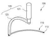
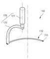
도 1은 본 발명인 주사장치를 나타낸 결합사시도.
도 2는 본 발명인 주사장치를 나타낸 분해사시도.
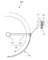
도 3은 본 발명인 주사장치에 수술사를 공급하는 상태를 나타낸 사시도.
도 4는 본 발명인 주사장치의 사용상태를 나타낸 정면도.
도 5는 본 발명인 주사장치의 주사바늘이 피부에 침투하는 상태를 나타낸 평면도.
도 6는 본 발명인 주사장치의 수술사가 피부에 침투된 상태를 나타낸 평면도.
도 7은 본 발명인 주사장치의 다른 실시예를 나타낸 사시도.
도 8은 본 발명인 주사장치의 또 다른 실시예를 나타낸 사시도.
도 9는 본 발명인 주사장치의 또 다른 실시예를 나타낸 사시도.
도 10은 본 발명인 주사장치의 표시부를 나타낸 사시도.
도 11은 본 발명인 주사장치의 표시부에 다양한 실시예를 나타낸 사시도.1 is a perspective view showing a combination injection device of the present invention.
Figure 2 is an exploded perspective view showing the injection device of the present invention.
Figure 3 is a perspective view showing a state of supplying a surgeon to the injection device of the present invention.
Figure 4 is a front view showing a state of use of the injection device of the present invention.
Figure 5 is a plan view showing a state in which the needle of the injection device of the present invention penetrates the skin.
Figure 6 is a plan view showing a state in which the surgeon of the injection device of the present invention penetrated the skin.
Figure 7 is a perspective view showing another embodiment of the present injection device.
Figure 8 is a perspective view showing another embodiment of the present invention injection device.
Figure 9 is a perspective view showing another embodiment of the present invention injection device.
10 is a perspective view showing a display portion of the present invention injection device.
11 is a perspective view showing various embodiments of the display unit of the present invention injection device.
이하 본 발명에 첨부된 도면을 참조하여 본 발명의 바람직한 일실시 예를 상세히 설명하기로 한다.Hereinafter, exemplary embodiments of the present invention will be described in detail with reference to the accompanying drawings.
우선, 도면들 중, 동일한 구성요소 또는 부품들은 가능한 동일한 참조부호로 나타내고 있음에 유의하여야 한다. 본 발명을 설명함에 있어, 관련된 공지기능 혹은 구성에 대한 구체적인 설명은 본 발명의 요지를 모호하지 않기 위하여 생략한다.First, in the drawings, it is noted that the same components or parts are denoted by the same reference numerals as possible. In describing the present invention, detailed descriptions of related well-known functions or configurations are omitted in order not to obscure the subject matter of the present invention.
도 1은 본 발명인 주사장치를 나타낸 결합사시도이고, 도 2는 본 발명인 주사장치를 나타낸 분해사시도이며, 도 3은 본 발명인 주사장치에 수술사를 공급하는 상태를 나타낸 사시도이고, 도 4는 본 발명인 주사장치의 사용상태를 나타낸 정면도이며, 도 5는 본 발명인 주사장치의 주사바늘이 피부에 침투하는 상태를 나타낸 평면도이고, 도 6는 본 발명인 주사장치의 수술사가 피부에 침투된 상태를 나타낸 평면도이며, 도 7은 본 발명인 주사장치의 다른 실시예를 나타낸 사시도이고, 도 8은 본 발명인 주사장치의 또 다른 실시예를 나타낸 사시도이며, 도 9는 본 발명인 주사장치의 또 다른 실시예를 나타낸 사시도이고, 도 10은 본 발명인 주사장치의 표시부를 나타낸 사시도이며, 도 11은 본 발명인 주사장치의 표시부에 다양한 실시예를 나타낸 사시도이다.1 is a combined perspective view showing the injection device of the present invention, Figure 2 is an exploded perspective view showing the injection device of the present invention, Figure 3 is a perspective view showing a state of supplying a surgeon to the injection device of the present invention, Figure 4 is the present inventor 5 is a plan view showing a state in which the needle of the injection device of the present invention penetrates into the skin, and FIG. 6 is a plan view showing a state where the surgeon of the injection device of the present invention penetrates into the skin. 7 is a perspective view showing another embodiment of the injection device of the present invention, Figure 8 is a perspective view showing another embodiment of the injection device of the present invention, Figure 9 is a perspective view showing another embodiment of the injection device of the
먼저, 도 1에 나타낸 바와 같이, 본 발명에 따른 주사장치 100의 구성상태를 살펴보면, 상기 수술사 10가 만곡되게 장착된 삽입수단을 회전시키는 회전수단을 통해 삽입수단이 회전하면서 피부에 침투되도록 한다.First, as shown in Figure 1, looking at the configuration of the
또한, 본 발명의 또 다른 측면에 의하면, 수술사 10가 장착되고 외주연이 만곡된 주사바늘 110을 회전시키는 조작부 120로 이루어져 있다.In addition, according to another aspect of the present invention, the
본 발명에 따른 주사장치 100에 대하여 보다 상세하게 살펴보면 다음과 같다. 도 1을 참조하면, 본 발명의 바람직한 일 실시예에 따른 주사장치 100는 수술사 10를 피부에 침투시키기 위한 주사바늘장치에 있어서, 상기 수술사 10가 장착되고 외주연이 만곡된 주사바늘 110과, 상기 주사바늘 110을 회전시키는 조작부 120를 포함하여, 상기 조작부 120의 운동력을 전달받아 주사바늘 110이 회전하면서 피부에 침투되도록 한다.Looking in more detail with respect to the
이때, 주사바늘 110의 내부에는 주입공 111이 관통되어 있다. 더불어, 주사바늘 110은 피부에 주입될 수 있도록 선단 113이 뾰족하게 형성되어 있다. 이러한, 주입공 111에는 수술사 10가 장착된다. 특히, 수술사 10에는 2열의 돌기 11가 형성될 수 있다. 이러한, 돌기 11는 실축의 한점을 기준으로 서로 대칭적으로 돌기 11가 형성됨이 바람직하다. 즉, 주입공 111에 장착되는 방향과 반대의 방향성을 갖는 다수의 돌기 11가 일정간격으로 이격되어 실축방향으로 형성된 수술사 10가 장착된다.At this time, the
상기와 같은 돌기 11는 다양한 수술상황에 맞도록 비대칭, 나선형 등 다양한 형태로 형성될 수 있다. 특히, 수술사 10는 주름 제거 시술에 적용되는 주름제거용 실, 모발이식 시술에 적용되는 자가모발 또는 인조모발을 비제한적인 예로서 설명하나, 의료용 고분자 소재로 생체 내 분해흡수성 또는 비 흡수성으로 이루어져 피부 조직에 주입 또는 이식되는 실 등을 포함함은 물론이다.The
이러한, 주사바늘 110은 가슴, 엉덩이, 복부와 같이 면적이 넓은 부위의 피부에 침투가 용이하도록 만곡되어 있다. 즉, 주사바늘 110은 만곡된 곡선 또는 하나 이상의 직선이 다각으로 꺾이면서 이음 연결된 형상인 것을 더 포함한다.The
결국, 가슴, 엉덩이, 복부와 같이 면적이 넓은 부위의 만곡된 라인과 동일하게 주사바늘 110이 침투되도록 하여, 시술시간이 단축된다.As a result, the
한편, 조작부 120는 길이당 구역별 상부 121와 하부 123로 구분한다. 먼저, 상부 121는 손으로 감사 쥐기 쉽도록 원기둥형상을 도시하였으나 이에 국한된 것은 아니다.On the other hand, the
더불어, 도 1에 도시한 바와 같이 조작부 120의 일 실시예는 주사바늘 110의 내측 중앙에 위치되게 설치하여 주사바늘 110을 정회전시킨다. 즉, 조작부 120의 상부 121는 직선의 직립된 상태로 형성되고 상기 하부 123는 바늘의 내측으로 향하도록 하여, 상부 121가 주사바늘 110의 내측 상부 121에 위치되도록 한다.In addition, as shown in FIG. 1, one embodiment of the
이때, 하부 123는 주사바늘 110에 연결된 부분을 기준으로 상향으로 만곡 또는 절곡시켜 주사바늘 110 상부로부터 상부 121가 이격되도록 한다. 이와 같은 하부 123에 가슴과 같이 돌출된 부분이 수용되도록 한다.In this case, the
그리고 도 7에 도시한 바와 같이 조작부 120의 다른 실시예는 주사바늘 110의 내측 중앙과 편심되게 상부 121가에 위치되게 설치하여 주사바늘 110을 편심회전시킨다.And another embodiment of the
또한, 도 8에 도시한 바와 같이 조작부 120의 또 다른 실시예는 주사바늘 110의 내측 중앙에 위치되게 설치하되, 조작부 120의 상부 121가 주사바늘 110과 수평되게 절곡시켜 하부 123 끝단을 중심으로 하여 주사바늘 110의 회전과 동일하게 상부 121를 회전시킨다. 이러한, 상부 121의 회전을 따라 주사바늘 110이 정회전 또는 편심회전한다.In addition, as shown in FIG. 8, another embodiment of the
더불어, 도 9에 도시된 바와 같이 조작부 120는 상부 121와 하부 123가 수직방향으로 동일하게 형성될 수도 있다. 이러한, 조작부 120를 주사바늘 110의 끝단에 직립되게 설치한다. 이러한, 조작부 120의 중심을 기준으로 회전하지 않고 주사바늘 110의 측면을 가압하는 방식으로 주사바늘 110을 피부 S에 침투시킨다. 더불어, 상부 121의 외주연에는 복수개의 돌기 또는 홈을 형성시켜 조작부 120의 조작이 더욱 용이하게 할 수도 있다.In addition, as illustrated in FIG. 9, the
결국, 주사바늘 110에 직립 또는 내측 상부에 위치된 조작부 120를 회전시키면 주사바늘 110이 편심 또는 정회전으로 회전하여, 가슴, 엉덩이, 복부와 같이 면적이 넓은 부위의 만곡된 라인을 따라 주사바늘 110을 용이하게 침투시킬 수 있어서, 시술의 정확성이 향상된다.As a result, when the
한편, 도 2 내지 도 3에 도시한 바와 같이 주사바늘 110에 수술사 10를 공급하는 방식은 장착형과 공급형으로 나누어진다. 이때, 수술사 10에는 2열의 돌기 11가 형성될 수 있다. 이러한, 돌기 11는 실축의 한점을 기준으로 서로 대칭적으로 돌기 11가 형성됨이 바람직하나, 다양한 수술상황에 맞도록 비대칭, 나선형 등 다양한 형태로 형성될 수 있다.On the other hand, as shown in Figures 2 to 3, the method of supplying the
먼저, 장착형은 도 2에 도시한 바와 같이 수술사 10가 장착된 주사바늘 110을 조작부 120에 끼움 결합하는 방식이다. 특히, 조작부 120 끝단에는 주사바늘 110과 대응된 형상의 결합공 125이 형성된다.First, the mounting type is a method of fitting the
여기서, 주사바늘 110에 삽입되는 수술사 10의 길이는 주사바늘 110의 길이와 대응된 길이로 장착될 수도 있고, 짧은 길이의 수술사 10가 복수개로 장착될 수도 있다.Here, the length of the
그리고 공급형은 도 3에 도시한 바와 같이 주사바늘 110의 주입공 111으로 수술사 10를 선택적으로 공급할 수 있다. 이때, 다양한 길이를 갖는 수술사 10를 연속적으로 공급할 수 있다. 더불어, 결합공 125의 단부에 경사진 안내면 127을 형성한다. 이러한, 안내면 127은 수술사 10의 공급을 원활하게 한다.The supply type may selectively supply the
이와 같이, 공급된 수술사 10를 인체로 삽입시키는 압력을 전달하는 곳으로 핀형상이나 속바늘과 같은 형태의 푸쉬핀(미도시)을 삽입하여 수술사 10를 밀어 피부 S 내부로 침투시킨다.As such, a push pin (not shown) in the form of a pin shape or a needle is inserted to the pressure S to insert the supplied
결국, 조작부 120의 끝단에 주사바늘 110이 탈착되게 결합함으로 인해, 주사바늘 110에 장착되는 수술사 10의 공급이 용이하여, 편의성이 증가한다.As a result, the
한편, 도 9에 도시된 바와 같이 주사바늘 110의 외주연에 표시부 130를 형성한다. 이때, 표시부 130는 주사바늘 110이 피부에 삽입되는 선단 113을 기준으로 수술사 10의 길이와 동일하게 형성한다. 이러한, 표시부 130를 통해 수술사 10의 길이와 동일한 깊이로 주사바늘 110이 피부에 삽입되는지를 확인할 수 있다.Meanwhile, as shown in FIG. 9, the
먼저, 도 11의 (a) 내지 (b)에 도시한 바와 같이 표시부 130를 띠로 형성할 수 있다. 이때, 도 11의 (a)와 같이 주사바늘 110의 외주연을 따라 표면에 표시부 130a를 마킹한다. 또는, 도 11의 (b)와 같이 주사바늘 110의 외주연을 따라 홈을 형성하고 그 안에 표시부 130b를 체워 놓을 수도 있다. 여기서, 표시부 130를 마킹하는 적합한 방법으로는 에칭 방식이 있으나 이에 국한된 것은 아니다. 여기서, 에칭방식이란 화학적인 부식작용을 이용한 가공법으로 필요 부분에 부식을 막기 위하여 마스킹(피복작업) 처리를 한다. 그리고 염화제 등의 부식제 등에 의하여 불요 부분을 녹임으로써 표시부 130가 형성되도록 한다.First, as illustrated in FIGS. 11A to 11B, the
더불어, 도 11의 (c)에 도시한 바와 같이, 주사바늘 110의 외주연을 따라 기계적인 홈이 형성된 표시부 130c가 형성될 수도 있다. 이러한, 표시부 130c의 홈은 외주연 전체에 홈을 낼 수도 있고 점진적으로 표시할 수도 있다.In addition, as shown in FIG. 11C, the
덧붙여, 도 11의 (d)에 도시한 바와 같이, 주사바늘 110의 외주연을 따라 외주연을 따라 돌기가 돌출된 표시부 130d가 형성된다. 이러한, 표시부 130d의 돌기는 외주연 전체를 따라 돌출될 수도 있고 등간격으로 돌출되어 표시할 수도 있다.In addition, as shown in FIG. 11D, a
결국, 주사바늘 110이 피부 S에 삽입되는 선단 113을 기준으로 수술사 10와 동일한 길이로 주사바늘 110 외주연에 표시부 130를 형성하여, 수술사 10의 길이를 외부에서 인식할 수 있도록 하여, 수술사 10의 길이와 동일한 깊이로 주사바늘 110이 피부 S에 삽입되는지를 확인할 수 있다.Eventually, the
더불어, 단순히 주사바늘 110이 삽입되는 깊이만을 확인하는 것을 넘어서, 시술자가 원하는 부위에 수술사 10를 정확히 삽입할 수 있도록 한다. 즉, 표시부 130를 이용하여 시술하게 되면 수술사 10의 위치와 양을 오류 없이 피부 면적에 맞출 수 있다.In addition, beyond simply checking the depth of the
한편, 주사바늘 110에는 다양한 길이를 갖는 수술사 10가 장착될 수도 있다. 이때, 주사바늘 110의 길이는 일정하나 장착된 수술사 10의 길이가 일정하지 않다.On the other hand, the
이처럼, 다양한 길이를 갖는 수술사 10에 맞추어 표시부 130를 하나 이상 형성한다. 이때, 수술사 10의 길이는 1cm 내지 6cm로 다양한 길이를 갖는다. 즉, 주사바늘 110이 피부에 삽입되는 선단 113을 기준으로 표시부 130까지의 거리는 다양한 수술사 10의 길이에 맞추어 복수개로 형성시킨다.As such, at least one
본 발명에 따른 주사장치에 작용을 살펴보면 다음과 같다.Looking at the operation of the injection device according to the present invention.
도 4 내지 도 5에 도시한 바와 같이 가슴, 엉덩이, 복부 등 시술이 필요한 피부 S의 시작점에 주사바늘 110의 선단 113을 맞춘다. 그리고 주사바늘 110에 결합된 조작부 120를 회전시키면 주사바늘 110이 편심 또는 정회전으로 회전하면서 피부 S에 침투한다. 이때, 조작부 120를 손으로 가볍게 쥔 상태에서 하부 123을 조작하여도 상부 121를 중심으로 하여 주사바늘 110이 회전하게 된다.As shown in Figs. 4 to 5, the
이와 같이, 도 6에 도시된 바와 같이, 침투된 주사바늘 110을 역으로 회전시키면서 인출시키면 주사바늘 100 내부에 장착되어 있거나, 외부에서 삽입시킨 수술사 10가 시술부위에 만곡되게 배치되면서 피부에 침투된다. 이처럼, 침투된 수술사 10의 전단력이 중심으로 몰리면서 가슴, 엉덩이, 복부 등을 모아주면서 올려주게 된다.As shown in FIG. 6, when the penetrated
결국, 수술사 10가 장착된 주사바늘 110을 편심 또는 정회전시키는 조작부 120를 포함하여, 주사바늘 110이 편심 또는 정회전하면서 피부에 침투되도록 하여 가슴, 엉덩이, 복부와 같이 면적이 넓은 부위를 용이하게 시술할 수 있어서, 주사바늘 110에 결합된 조작부 120의 위치에 따라 수술사 10가 호, 진원, 타원, 유선형 중 하나 이상의 형상으로 피부 내에 배치되어 시술의 만족도가 향상된다.As a result, including the
이상에서 설명한 본 발명은 전술한 실시예 및 첨부된 도면에 의해 한정되는 것은 아니고, 본 발명의 기술적 사상을 벗어나지 않는 범위 내에서 여러 가지 치환, 변형 및 변경할 수 있음은 본 발명이 속하는 기술분야에서 통상의 지식을 가진 자에게 있어서 명백할 것이다.
While the present invention has been described in connection with what is presently considered to be practical exemplary embodiments, it is to be understood that the invention is not limited to the disclosed embodiments, but, on the contrary, It will be clear to those who have knowledge of.
* 도면의 주요부분에 대한 부호의 설명 *
10 : 수술사11 : 돌기
100 : 주사장치110 : 주사바늘
111 : 주입공113 : 선단
120 : 조작부121 : 상부
123 : 하부125 : 결합공
127 : 안내면130 : 표시부Description of the Related Art [0002]
10: surgeon 11: protrusion
100: injection device 110: injection needle
111: injection hole 113: tip
120: operation unit 121: upper part
123: lower part 125: coupling hole
127: guide surface 130: display unit
Claims (12)
Translated fromKorean상기 수술사가 장착되고 외주연이 만곡된 주사바늘과,
상기 주사바늘을 회전시키는 조작부를 포함하되,
상기 주사바늘은,
상기 조작부의 끝단에 탈착되게 결합하여,
상기 조작부의 운동력을 전달받아 주사바늘이 회전하면서 피부에 침투되도록 한 주사장치.
In the needle device for penetrating the skin to the surgeon,
The needle is equipped with the surgeon and the outer circumference is curved,
Including an operation unit for rotating the needle,
The needle,
Coupled to the end of the operation unit detachably,
Injecting device for receiving the movement force of the operation unit to penetrate the skin while the injection needle rotates.
상기 조작부는,
길이당 구역별 상부와 하부로 구분하되,
상기 상부는 직선의 직립된 상태로 형성되고 상기 하부는 바늘의 내측으로 향하도록 주사바늘과 결합하여, 상부가 주사바늘의 내측 상부에 위치되도록 한 것을 특징으로 하는 주사장치.
The method of claim 3,
Wherein,
Divided into upper and lower sections by length per length,
The upper portion is formed in a straight upright state and the lower portion is coupled to the needle so as to face the inner side of the needle, characterized in that the upper portion is located on the inner upper portion of the needle.
상기 조작부는,
상기 주사바늘의 중심과 상부의 중심이 일치되게 위치하여 주사바늘을 정회전시키는 것을 특징으로 하는 주사장치.
5. The method of claim 4,
Wherein,
The injection device, characterized in that the center of the needle and the center of the upper portion is aligned to rotate the needle forward.
상기 조작부는,
상기 주사바늘의 중심과 상부의 중심이 편심되게 위치하여 주사바늘을 편심 회전시키는 것을 특징으로 하는 주사장치.
5. The method of claim 4,
Wherein,
The center of the needle and the center of the upper portion of the injection device characterized in that the eccentric rotation of the needle.
상기 조작부는,
상기 주사바늘과 대응된 형상의 결합공이 끝단에 형성되되, 상기 결합공의 단부에 안내면을 형성시킨 것을 더 포함하는 주사장치.
The method of claim 3,
Wherein,
And a coupling hole having a shape corresponding to the needle, formed at an end thereof, and having a guide surface formed at an end of the coupling hole.
상기 주사바늘의 외주연에 표시부를 형성하되,
상기 표시부는 주사바늘이 피부에 삽입되는 선단을 기준으로 수술사의 길이와 동일하게 형성하여, 상기 수술사의 길이와 동일한 깊이로 주사바늘이 피부에 삽입되는지를 확인할 수 있도록 한 것을 포함하는 주사장치.
The method of claim 3,
The display unit is formed on the outer circumference of the needle,
And the display unit is formed to have the same length as that of the surgeon based on the tip of the needle inserted into the skin, so that the needle can be inserted into the skin at the same depth as the length of the surgeon.
상기 표시부는,
띠, 홈, 돌기로 이루어진 군에서 하나를 선택적으로 적용할 수 있는 것을 특징으로 하는 주사장치.
10. The method of claim 9,
The display unit includes:
Injector, characterized in that can be selectively applied in the group consisting of a band, groove, projection.
상기 표시부는,
다양한 길이를 갖는 수술사에 맞추어 하나 이상 형성시킨 것을 포함하는 주사장치.10. The method of claim 9,
The display unit includes:
Injection device comprising one or more formed in accordance with the surgeon having a varying length.
상기 주사바늘이 결합된 조작부의 위치에 따라 수술사가 호, 진원, 타원, 유선형 중 하나 이상의 형상으로 피부 내에 배치되도록 한 것을 특징으로 하는 주사장치.The method of claim 3,
Injector according to the position of the operation portion coupled to the needle injection device, characterized in that arranged in the skin in one or more of the shape of arc, round, ellipse, streamline.
Priority Applications (1)
| Application Number | Priority Date | Filing Date | Title |
|---|---|---|---|
| KR1020110036994AKR101275683B1 (en) | 2011-04-20 | 2011-04-20 | Inject device |
Applications Claiming Priority (1)
| Application Number | Priority Date | Filing Date | Title |
|---|---|---|---|
| KR1020110036994AKR101275683B1 (en) | 2011-04-20 | 2011-04-20 | Inject device |
Publications (2)
| Publication Number | Publication Date |
|---|---|
| KR20120119187A KR20120119187A (en) | 2012-10-30 |
| KR101275683B1true KR101275683B1 (en) | 2013-06-14 |
Family
ID=47286481
Family Applications (1)
| Application Number | Title | Priority Date | Filing Date |
|---|---|---|---|
| KR1020110036994AActiveKR101275683B1 (en) | 2011-04-20 | 2011-04-20 | Inject device |
Country Status (1)
| Country | Link |
|---|---|
| KR (1) | KR101275683B1 (en) |
Families Citing this family (1)
| Publication number | Priority date | Publication date | Assignee | Title |
|---|---|---|---|---|
| KR101973845B1 (en)* | 2017-02-21 | 2019-04-30 | 류시대 | Embedding therapy tool and using method thereof |
Citations (4)
| Publication number | Priority date | Publication date | Assignee | Title |
|---|---|---|---|---|
| JPH08117239A (en)* | 1994-10-20 | 1996-05-14 | Terumo Corp | Suturing device |
| JP2003052702A (en)* | 2001-08-16 | 2003-02-25 | Kishino Shoji | Suturing apparatus |
| JP3384573B2 (en)* | 1992-08-20 | 2003-03-10 | オリンパス光学工業株式会社 | Surgery system |
| US20060173491A1 (en)* | 2001-06-14 | 2006-08-03 | Suturtek Incorporated | Needle for suturing instrument |
- 2011
- 2011-04-20KRKR1020110036994Apatent/KR101275683B1/enactiveActive
Patent Citations (4)
| Publication number | Priority date | Publication date | Assignee | Title |
|---|---|---|---|---|
| JP3384573B2 (en)* | 1992-08-20 | 2003-03-10 | オリンパス光学工業株式会社 | Surgery system |
| JPH08117239A (en)* | 1994-10-20 | 1996-05-14 | Terumo Corp | Suturing device |
| US20060173491A1 (en)* | 2001-06-14 | 2006-08-03 | Suturtek Incorporated | Needle for suturing instrument |
| JP2003052702A (en)* | 2001-08-16 | 2003-02-25 | Kishino Shoji | Suturing apparatus |
Also Published As
| Publication number | Publication date |
|---|---|
| KR20120119187A (en) | 2012-10-30 |
Similar Documents
| Publication | Publication Date | Title |
|---|---|---|
| KR101391659B1 (en) | Medical thread and apparatus for inserting medical thread | |
| KR101371948B1 (en) | Needle device for thread embedding of acupuncture. | |
| EP3020430B1 (en) | Cannula for catgut-embedding therapy | |
| BR112013019304B1 (en) | APPLIANCE TO PRODUCE COSMETIC EFFECT IN A SKIN TISSUE REGION AND NON-THERAPEUTIC COSMETIC METHOD TO RECOMMEND A SKIN TISSUE REGION | |
| CN106714890B (en) | Device for inserting a blunt cannula beneath the skin of a patient | |
| JP3140303U (en) | Double heel surgery tweezers | |
| JP2013034743A (en) | Acupuncture needle | |
| US8257392B2 (en) | Intimacy medical needle designed for nerve stimulation through soft tissue and microadhesiolysis of adhered soft tissue and medical instrument using the same | |
| KR101275683B1 (en) | Inject device | |
| US20240189506A1 (en) | Infiltration cannula with dual angle configuration | |
| CN204765811U (en) | Disposable multi -purpose wicresoft water needle sword | |
| KR20140005581A (en) | Needle set for skin plasty surgical operation | |
| KR102071786B1 (en) | Syringe for lifting | |
| CN102921075A (en) | Anesthesia operation puncture needle with diversion groove | |
| KR200467516Y1 (en) | Thread needle a insertion depth marked | |
| KR20160056683A (en) | Embedding therapy needle | |
| KR20190117192A (en) | Syringe for lifting | |
| CN209712999U (en) | Thread embedding needle instrument | |
| CN101874745A (en) | Multifunctional cord-embedding needle | |
| CN209360829U (en) | A kind of cutting edge needle knife for injection thread embedding needle instrument | |
| CN201806734U (en) | Multifunctional thread-burial needle | |
| CN105852923A (en) | Achilles tendon minimally-invasive suture instrument set | |
| KR20210087157A (en) | Needle unit for the skin care device | |
| Hertzog et al. | The flexible needle, a safe and easy new technique to inject the face | |
| KR200438746Y1 (en) | Double Eyelid Surgical Tweezers |
Legal Events
| Date | Code | Title | Description |
|---|---|---|---|
| A201 | Request for examination | ||
| PA0109 | Patent application | Patent event code:PA01091R01D Comment text:Patent Application Patent event date:20110420 | |
| PA0201 | Request for examination | ||
| E902 | Notification of reason for refusal | ||
| PE0902 | Notice of grounds for rejection | Comment text:Notification of reason for refusal Patent event date:20121025 Patent event code:PE09021S01D | |
| PG1501 | Laying open of application | ||
| E701 | Decision to grant or registration of patent right | ||
| PE0701 | Decision of registration | Patent event code:PE07011S01D Comment text:Decision to Grant Registration Patent event date:20130529 | |
| GRNT | Written decision to grant | ||
| PR0701 | Registration of establishment | Comment text:Registration of Establishment Patent event date:20130611 Patent event code:PR07011E01D | |
| PR1002 | Payment of registration fee | Payment date:20130612 End annual number:3 Start annual number:1 | |
| PG1601 | Publication of registration | ||
| FPAY | Annual fee payment | Payment date:20160602 Year of fee payment:4 | |
| PR1001 | Payment of annual fee | Payment date:20160602 Start annual number:4 End annual number:4 | |
| FPAY | Annual fee payment | Payment date:20170607 Year of fee payment:5 | |
| PR1001 | Payment of annual fee | Payment date:20170607 Start annual number:5 End annual number:5 | |
| FPAY | Annual fee payment | Payment date:20180612 Year of fee payment:6 | |
| PR1001 | Payment of annual fee | Payment date:20180612 Start annual number:6 End annual number:6 | |
| FPAY | Annual fee payment | Payment date:20190605 Year of fee payment:7 | |
| PR1001 | Payment of annual fee | Payment date:20190605 Start annual number:7 End annual number:7 | |
| PR1001 | Payment of annual fee | Payment date:20200602 Start annual number:8 End annual number:8 | |
| PR1001 | Payment of annual fee | Payment date:20210602 Start annual number:9 End annual number:9 | |
| PR1001 | Payment of annual fee | Payment date:20230601 Start annual number:11 End annual number:11 | |
| PR1001 | Payment of annual fee | Payment date:20250604 Start annual number:13 End annual number:13 |