KR101272440B1 - Video signal output device for providing data signal using back light unit and method thereof - Google Patents
Video signal output device for providing data signal using back light unit and method thereofDownload PDFInfo
- Publication number
- KR101272440B1 KR101272440B1KR1020060101379AKR20060101379AKR101272440B1KR 101272440 B1KR101272440 B1KR 101272440B1KR 1020060101379 AKR1020060101379 AKR 1020060101379AKR 20060101379 AKR20060101379 AKR 20060101379AKR 101272440 B1KR101272440 B1KR 101272440B1
- Authority
- KR
- South Korea
- Prior art keywords
- signal
- backlight unit
- data signal
- video signal
- output device
- Prior art date
- Legal status (The legal status is an assumption and is not a legal conclusion. Google has not performed a legal analysis and makes no representation as to the accuracy of the status listed.)
- Expired - Fee Related
Links
Images


Classifications
- G—PHYSICS
- G09—EDUCATION; CRYPTOGRAPHY; DISPLAY; ADVERTISING; SEALS
- G09G—ARRANGEMENTS OR CIRCUITS FOR CONTROL OF INDICATING DEVICES USING STATIC MEANS TO PRESENT VARIABLE INFORMATION
- G09G3/00—Control arrangements or circuits, of interest only in connection with visual indicators other than cathode-ray tubes
- G09G3/20—Control arrangements or circuits, of interest only in connection with visual indicators other than cathode-ray tubes for presentation of an assembly of a number of characters, e.g. a page, by composing the assembly by combination of individual elements arranged in a matrix no fixed position being assigned to or needed to be assigned to the individual characters or partial characters
- G09G3/34—Control arrangements or circuits, of interest only in connection with visual indicators other than cathode-ray tubes for presentation of an assembly of a number of characters, e.g. a page, by composing the assembly by combination of individual elements arranged in a matrix no fixed position being assigned to or needed to be assigned to the individual characters or partial characters by control of light from an independent source
- G09G3/3406—Control of illumination source
- G—PHYSICS
- G09—EDUCATION; CRYPTOGRAPHY; DISPLAY; ADVERTISING; SEALS
- G09G—ARRANGEMENTS OR CIRCUITS FOR CONTROL OF INDICATING DEVICES USING STATIC MEANS TO PRESENT VARIABLE INFORMATION
- G09G3/00—Control arrangements or circuits, of interest only in connection with visual indicators other than cathode-ray tubes
- G09G3/20—Control arrangements or circuits, of interest only in connection with visual indicators other than cathode-ray tubes for presentation of an assembly of a number of characters, e.g. a page, by composing the assembly by combination of individual elements arranged in a matrix no fixed position being assigned to or needed to be assigned to the individual characters or partial characters
- G09G3/34—Control arrangements or circuits, of interest only in connection with visual indicators other than cathode-ray tubes for presentation of an assembly of a number of characters, e.g. a page, by composing the assembly by combination of individual elements arranged in a matrix no fixed position being assigned to or needed to be assigned to the individual characters or partial characters by control of light from an independent source
- G09G3/36—Control arrangements or circuits, of interest only in connection with visual indicators other than cathode-ray tubes for presentation of an assembly of a number of characters, e.g. a page, by composing the assembly by combination of individual elements arranged in a matrix no fixed position being assigned to or needed to be assigned to the individual characters or partial characters by control of light from an independent source using liquid crystals
- H—ELECTRICITY
- H04—ELECTRIC COMMUNICATION TECHNIQUE
- H04N—PICTORIAL COMMUNICATION, e.g. TELEVISION
- H04N7/00—Television systems
- H04N7/08—Systems for the simultaneous or sequential transmission of more than one television signal, e.g. additional information signals, the signals occupying wholly or partially the same frequency band, e.g. by time division
- G—PHYSICS
- G09—EDUCATION; CRYPTOGRAPHY; DISPLAY; ADVERTISING; SEALS
- G09G—ARRANGEMENTS OR CIRCUITS FOR CONTROL OF INDICATING DEVICES USING STATIC MEANS TO PRESENT VARIABLE INFORMATION
- G09G2370/00—Aspects of data communication
- G09G2370/08—Details of image data interface between the display device controller and the data line driver circuit
Landscapes
- Engineering & Computer Science (AREA)
- Physics & Mathematics (AREA)
- Computer Hardware Design (AREA)
- General Physics & Mathematics (AREA)
- Theoretical Computer Science (AREA)
- Multimedia (AREA)
- Signal Processing (AREA)
- Chemical & Material Sciences (AREA)
- Crystallography & Structural Chemistry (AREA)
- Two-Way Televisions, Distribution Of Moving Picture Or The Like (AREA)
Abstract
Translated fromKoreanDescription
Translated fromKorean도 1은 본 발명의 실시 예에 따라 가시광 통신을 위한 영상 신호 수신 단말기와 영상 신호 출력 장치를 나타낸 예시도,1 is an exemplary view showing a video signal receiving terminal and a video signal output device for visible light communication according to an embodiment of the present invention;
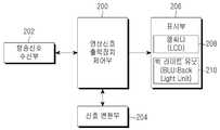
도 2는 본 발명의 실시 예가 적용되는 영상 신호 출력 장치의 블록 구성도,2 is a block diagram of an image signal output apparatus to which an embodiment of the present invention is applied;
도 3은 본 발명의 실시 예가 적용되는 영상 신호 수신 단말기의 블록 구성도,3 is a block diagram of a video signal receiving terminal to which an embodiment of the present invention is applied;
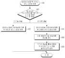
도 4는 본 발명의 실시 예에 따라 방송 신호로부터 분리된 데이터 신호를 백 라이트 유닛 신호로 변환하여 출력하기 위한 과정을 도시한 흐름도,4 is a flowchart illustrating a process for converting a data signal separated from a broadcast signal into a backlight unit signal according to an embodiment of the present invention and outputting the same;
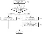
도 5는 본 발명의 실시 예에 따라 백 라이트 유닛 신호의 출력 방식을 고려하여 데이터 신호를 백 라이트 유닛 신호로 변환하는 과정을 도시한 흐름도,5 is a flowchart illustrating a process of converting a data signal into a backlight unit signal in consideration of an output method of the backlight unit signal according to an embodiment of the present invention;
도 6은 본 발명의 실시 예에 따라 영상 신호 출력 장치로부터 수신된 백 라이트 유닛 신호를 데이터 신호로 변환하여 변환된 데이터를 화상정보로 출력하기 위한 과정을 도시한 흐름도,6 is a flowchart illustrating a process of converting a backlight unit signal received from an image signal output device into a data signal and outputting the converted data as image information according to an embodiment of the present invention;
도 7은 본 발명의 실시 예에 따라 백 라이트 유닛 신호의 출력 방식을 고려 하여 백 라이트 유닛 신호를 수신하는 과정을 도시한 흐름도.7 is a flowchart illustrating a process of receiving a backlight unit signal in consideration of an output method of the backlight unit signal according to an exemplary embodiment of the present invention.
본 발명은 데이터 신호를 수신하는 것에 관한 것으로, 특히, 백 라이트 유닛(BLU : Back Light Unit)을 활용한 데이터 신호 수신 방법에 관한 것이다.The present invention relates to receiving a data signal, and more particularly, to a method of receiving a data signal utilizing a back light unit (BLU).
최근, TFT-LCD(Thin Film Transistor Liquid Ctystal Display)와 같은 영상 신호 수신 장치가 디지털 멀티미디어 기기의 핵심 디스플레이로 부상하고 있다. 그 이유로, 상기한 영상 신호 수신 장치는 기존의 CRT(Cathode-Ray Tube) 방식의 영상 신호 수신 장치에 비해 저 전력 소모, 눈의 피로감 감소, 장치 두께의 감소 등의 장점을 포함하고 있기 때문이다. 하지만, TFT-LCD와 같은 영상 신호 출력 장치는 자체적으로 발광을 할 수 없기 때문에 외부의 광원이 필요하다. 따라서, 이러한 TFT-LCD와 같은 영상 신호 수신 장치에는 빛을 제공하기 위한 백 라이트 유닛이 필수적으로 사용된다.Recently, video signal receivers such as thin film transistor liquid crystal displays (TFT-LCDs) are emerging as core displays of digital multimedia devices. For this reason, the video signal receiver includes advantages such as low power consumption, reduced eye strain, and reduced device thickness compared to conventional CRT (Cathode-Ray Tube) video signal receivers. However, since an image signal output device such as a TFT-LCD cannot emit light by itself, an external light source is required. Therefore, a backlight unit for providing light is essentially used in a video signal receiving apparatus such as a TFT-LCD.
상기한 백 라이트 유닛의 발광체로 냉음극형광램프(CCFL : Cold Cathode Fluorescent Lamp), 열음극형광램프(HCFL : Hot Cathode Fluorescent Lamp), 발광 다이오드(LED : Light Emitting Diode)등이 사용되고 있다.As the light emitter of the backlight unit, a cold cathode fluorescent lamp (CCFL), a hot cathode fluorescent lamp (HCFL), a light emitting diode (LED), and the like are used.
이러한 백 라이트 유닛의 발광체들 중 발광 다이오드는 관측자가 본 물체의 단위 면적당 광도를 나타내는 휘도, 적은 전력 소모 그리고 긴 수명의 장점을 가지 고 있다.Among the light emitting units of such a backlight unit, the light emitting diode has advantages of brightness, low power consumption, and long life, which represent the brightness per unit area of the object viewed by the observer.
상술한 발광 다이오드의 장점으로 인해 백 라이트 유닛의 발광체로서 발광 다이오드를 탑재하고 있으나, TFT-LCD와 같은 영상 신호 수신 장치에 빛을 제공하는 방법 이외에 발광 다이오드를 활용하여 데이터 신호를 전송하는 방법은 아직 없는 실정이다.Due to the advantages of the above-described light emitting diode, the light emitting diode is mounted as a light emitting unit of the backlight unit. However, in addition to providing light to an image signal receiving apparatus such as a TFT-LCD, a method of transmitting a data signal by using the light emitting diode is not yet available. There is no situation.
그러므로, 본 발명의 목적은, TFT-LCD와 같은 영상 신호 수신 장치에서 백 라이트 유닛으로 사용되는 발광 다이오드를 활용하여 데이터 신호를 전송하는 장치 및 방법을 제공함에 있다.It is therefore an object of the present invention to provide an apparatus and method for transmitting a data signal utilizing a light emitting diode used as a backlight unit in an image signal receiving apparatus such as a TFT-LCD.
상술한 목적을 달성하기 위한 본 발명의 장치는, 백 라이트 유닛을 이용하여 데이터 신호를 제공하기 위한 영상 신호 출력 장치에 있어서, 방송 신호를 수신하는 방송 신호 수신부와, 상기 수신된 방송 신호에 데이터가 포함되어 있는 경우, 상기 방송 신호에 포함된 비디오 신호와 데이터 신호를 분리하고, 분리된 데이터 신호를 기 설정된 백 라이트 유닛 신호의 출력 방식에 따라 백 라이트 유닛 신호로 변환하는 신호 변환부와, 상기 비디오 신호와 상기 백 라이트 유닛 신호로 변환된 데이터 신호를 출력하는 표시부와, 상기 방송 신호에 데이터 신호가 포함되어 있는지 감지하고, 데이터 신호가 포함되어 있는 경우, 상기 신호 변환부와 표시부를 제 어하여 상기 분리된 데이터 신호가 상기 기 설정된 백 라이트 유닛 출력 방식에 따라 출력 되도록 하는 영상 신호 출력 장치 제어부를 포함한다.According to an aspect of the present invention, there is provided a video signal output apparatus for providing a data signal using a backlight unit, the apparatus comprising: a broadcast signal receiving unit for receiving a broadcast signal, and data in the received broadcast signal; A signal converter which separates a video signal and a data signal included in the broadcast signal, and converts the separated data signal into a backlight unit signal according to a preset backlight unit signal output method; A display unit for outputting a signal and a data signal converted into the backlight unit signal, and detecting whether a data signal is included in the broadcast signal, and controlling the signal converter and the display unit if the data signal is included. The separated data signal may be output according to the preset backlight unit output method. And a video signal output device controller.
그리고, 백 라이트 유닛을 활용하여 데이터 신호를 제공받기 위한 영상 신호 수신 단말기에 있어서, 영상 신호를 출력하는 영상 신호 출력 장치로부터 데이터 신호가 변환된 백 라이트 유닛 신호가 수신되는 경우, 이를 감지할 수 있는 백 라이트 유닛 감지 정보를 저장하는 메모리부와, 상기 백 라이트 유닛 감지 정보를 이용하여, 상기 영상 신호 출력 장치로부터 데이터 신호가 변환된 백 라이트 유닛 신호가 수신되었는지를 감지하는 광 데이터 감지부와, 상기 백 라이트 유닛 신호가 감지되면, 상기 백 라이트 유닛 신호를 수신하는 백 라이트 유닛 신호 수신부와, 상기 수신된 백 라이트 유닛 신호를 데이터 신호로 변환하고, 변환된 데이터 신호를 화상 정보로 출력하는 단말기 제어부를 포함하는 것을 특징으로 한다.In addition, in the image signal receiving terminal for receiving a data signal by using the backlight unit, when the backlight unit signal converted from the data signal is received from the image signal output device for outputting the image signal, it may be detected. A memory unit for storing backlight unit sensing information, an optical data sensing unit for sensing whether a backlight unit signal converted from a data signal is received from the image signal output apparatus using the backlight unit sensing information, and When a backlight unit signal is detected, a backlight unit signal receiver for receiving the backlight unit signal, and a terminal controller for converting the received backlight unit signal into a data signal and outputting the converted data signal as image information. It is characterized by including.
또한, 방법은, 영상 신호 출력 장치가 백 라이트 유닛을 이용하여 데이터 신호를 제공하기 위한 방법에 있어서, 방송 신호가 수신되면, 상기 방송 신호에 데이터 신호가 포함되어 있는지 체크하는 단계와, 상기 방송 신호에 데이터 신호가 포함되어 있는 경우, 상기 방송 신호로부터 비디오 신호와 데이터 신호를 분리하여 저장하는 단계와, 상기 데이터 신호를 백 라이트 유닛 신호로 변환하는 단계와, 상기 비디오 신호와 상기 백 라이트 유닛 신호로 변환된 데이터 신호를 출력하는 단계를 포함하는 것을 특징으로 한다.In addition, the method is a method for providing a data signal by using a backlight unit, the image signal output device, if a broadcast signal is received, checking whether the data signal is included in the broadcast signal, and the broadcast signal And storing the video signal and the data signal separately from the broadcast signal, converting the data signal into a backlight unit signal, and converting the video signal into the backlight unit signal. And outputting the converted data signal.
그리고, 영상 신호 출력 장치의 백 라이트 유닛을 통해 데이터 신호를 수신하고 이를 사용자에게 제공하기 위한 방법에 있어서, 영상 신호 수신 단말기가, 데 이터 신호가 변환된 백 라이트 유닛 신호가 감지되었는지 여부를 체크하는 단계와, 상기 체크 결과 상기 백 라이트 유닛 신호가 감지된 경우이면 상기 백 라이트 유닛 신호를 수신하는 단계와, 상기 수신된 백 라이트 유닛 신호를 데이터 신호로 변환하는 단계와, 상기 사용자로부터 상기 변환된 데이터 신호의 출력을 위한 입력이 있는지 체크하는 단계와, 상기 사용자로부터 상기 변환된 데이터 신호의 출력을 위한 입력이 있는 경우, 상기 변환된 데이터 신호를 상기 영상 신호 수신 단말기의 표시부에서 표시 가능한 화상정보로 출력하는 단계를 포함하는 것을 특징으로 한다.In the method for receiving a data signal through a backlight unit of an image signal output device and providing the same to a user, the image signal receiving terminal checks whether a backlight unit signal converted from the data signal is detected. And if the backlight unit signal is detected as a result of the check, receiving the backlight unit signal, converting the received backlight unit signal into a data signal, and converting the converted data from the user. Checking whether there is an input for outputting a signal, and if there is an input for outputting the converted data signal from the user, outputting the converted data signal as image information displayable on a display unit of the video signal receiving terminal Characterized in that it comprises a step.
이하 본 발명의 바람직한 실시 예를 첨부한 도면을 참조하여 상세히 설명한다. 도면들 중 동일한 구성요소들은 가능한 한 어느 곳에서든지 동일한 부호들로 나타내고 있음에 유의하여야 한다. 하기 설명 및 첨부 도면에서 본 발명의 요지를 불필요하게 흐릴 수 있는 공지 기능 및 구성에 대한 상세한 설명은 생략한다. 또한 이하의 설명에서는 백 라이트 유닛으로서 발광 다이오드를 사용하는 것을 가정하여 설명하기로 한다. 그러나 이는 본 발명의 실시 예 일뿐 이에 본 발명이 국한되는 것은 아니다. 즉, 상기 발광 다이오드 외에 다른 발광체를 사용할 수도 있음은 물론이다.Hereinafter, preferred embodiments of the present invention will be described in detail with reference to the accompanying drawings. It should be noted that the same elements in the figures are represented by the same numerals wherever possible. In the following description and the annexed drawings, detailed descriptions of well-known functions and configurations that may unnecessarily obscure the subject matter of the present invention will be omitted. In the following description, it is assumed that a light emitting diode is used as the backlight unit. However, this is only an embodiment of the present invention and the present invention is not limited thereto. That is, of course, other light emitters may be used in addition to the light emitting diodes.
먼저 본 발명의 완전한 이해를 돕기 위해, 본 발명의 기본 원리를 설명하면, 본 발명에서 영상 신호 출력 장치는 케이블, 안테나, PLC(Power Line Communication), LAN(Local Area Network)을 통해 방송 신호를 수신하고, 수신된 방송 신호에 데이터 신호가 포함되어 있는지 체크한다. 이때, 수신된 방송 신호에 데이터 신호가 포함되어 있으면, 비디오 신호와 데이터 신호를 분리한다. 이후, 영상 신호 출력 장치는 분리된 데이터 신호를 백 라이트 유닛 신호의 출력 방식이 단일 또는 다중 채널인지 여부에 따라 상기 데이터 신호를 단일 채널 또는 다중 채널의 백 라이트 유닛 신호로 변환하고, 비디오 신호와 백 라이트 유닛 신호를 영상 신호 출력 장치의 화면을 통해 각각 출력한다.First of all, in order to provide a thorough understanding of the present invention, the basic principles of the present invention will be described. Then, it is checked whether a data signal is included in the received broadcast signal. At this time, if a data signal is included in the received broadcast signal, the video signal and the data signal are separated. Thereafter, the image signal output apparatus converts the separated data signal into a single channel or a multi channel backlight unit signal according to whether the backlight unit signal output method is a single channel or a multi channel, and the video signal and the back signal. The light unit signals are output through the screen of the video signal output device.
이때, 백 라이트 유닛 신호의 출력은 발광 다이오드를 깜박거림으로써 데이터 신호를 출력한다. 예를 들어, 발광 다이오드가 켜지면 1, 꺼지면 0으로 데이터 신호를 출력한다. 이때, 발광 다이오드가 깜박거리는 주기가 100KHz 이상이면, 사용자는 깜박거림을 느끼지 못하기 때문에 발광 다이오드의 깜박거림으로 인한 눈의 피로감 등의 불편함을 해결할 수 있다.At this time, the output of the backlight unit signal outputs a data signal by blinking the light emitting diode. For example, a light emitting diode outputs a data signal as 1 when it is turned on and 0 when turned off. In this case, when the period of blinking the light emitting diode is 100 KHz or more, since the user does not feel the blinking, inconvenience such as eye fatigue due to the blinking of the light emitting diode may be solved.
또한, 본 발명에서 영상 신호 수신 단말기는 카메라를 통해 백 라이트 유닛 신호를 감지한 경우, 백 라이트 유닛 신호의 출력 방식이 단일 또는 다중 채널인지의 여부를 확인하고, 확인 결과에 따라 백 라이트 유닛 신호를 데이터 신호로 변환한 후, 사용자의 선택에 따라 데이터 신호를 화상 정보로 출력한다.In addition, in the present invention, when the image signal receiving terminal detects the backlight unit signal through a camera, the terminal determines whether the output unit of the backlight unit signal is a single channel or a multiple channel, After conversion to a data signal, the data signal is output as image information according to the user's selection.
도 1은 이러한 본 발명의 실시 예에 따라 가시광 통신을 통해 데이터를 송신하는 영상 신호 출력 장치와 데이터를 수신하는 영상 신호 수신 단말기를 보인 도면이다. 도 1을 살펴보면, 도 1의 (a)는 백 라이트 유닛인 발광 다이오드의 개수가 하나인 경우 또는 여러 개의 발광 다이오드가 동일한 신호를 송출할 경우의 영상 신호 출력 장치와 영상 신호 수신 단말기 간에 가시광 통신을 하는 예를 보인 것이다.FIG. 1 is a diagram illustrating a video signal output device for transmitting data through visible light communication and a video signal receiving terminal for receiving data according to an exemplary embodiment of the present invention. Referring to FIG. 1, FIG. 1A illustrates visible light communication between a video signal output device and a video signal receiving terminal when the number of light emitting diodes as a backlight unit is one or when a plurality of light emitting diodes transmit the same signal. This is an example.
그리고, 도 1의 (b)는 백 라이트 유닛인 다수 개의 발광 다이오드들 중 하나의 발광 다이오드를 사용하여 데이터 신호를 전송하는 경우의 영상 신호 출력 장치와 영상 신호 수신 단말기 간의 가시광 통신 예를 보인 것이다. 따라서, 상기 도 1의 (a)와 도 1의 (b)와 같은 경우, 영상 신호 출력 장치는 하나의 백 라이트 유닛만을 이용하여 데이터 신호를 전송하므로, 영상 신호 출력 장치와 영상 신호 수신 단말기 간에 데이터 신호가 전송되는 하나의 채널만이 생성된다.1B illustrates an example of visible light communication between an image signal output device and an image signal receiving terminal when a data signal is transmitted using one of the plurality of light emitting diodes as a backlight unit. Therefore, in the case of FIGS. 1A and 1B, since the video signal output device transmits a data signal using only one backlight unit, data is transmitted between the video signal output device and the video signal receiving terminal. Only one channel over which a signal is transmitted is created.
한편, 도 1의 (c)는 백 라이트 유닛인 다수 개의 발광 다이오드들 중 다수 개의 발광 다이오드들을 사용할 경우의 영상 신호 출력 장치와 영상 신호 수신 단말기 간의 가시광 통신 예를 보인 것이다. 따라서, 본 발명의 실시 예에 따른 영상 신호 출력 장치는 다수 개의 발광 다이오드들을 사용하여 데이터 신호를 영상 신호 수신 단말기로 전송한다. 그러므로, 이러한 경우, 상기 영상 신호 출력 장치와 영상 신호 수신 단말기 사이에는 데이터 신호가 전송되는 다수의 채널이 형성된다.FIG. 1C illustrates an example of visible light communication between an image signal output device and an image signal receiving terminal when a plurality of light emitting diodes, which are backlight units, are used. Accordingly, the image signal output apparatus according to an embodiment of the present invention transmits a data signal to the image signal receiving terminal using a plurality of light emitting diodes. Therefore, in this case, a plurality of channels through which data signals are transmitted are formed between the video signal output device and the video signal receiving terminal.
도 2는 이러한 본 발명의 실시 예에 따른 영상 신호 출력 장치의 블록 구성도를 보이고 있는 도면이다.2 is a block diagram illustrating a video signal output apparatus according to an exemplary embodiment of the present invention.
도 2를 참조하여 살펴보면, 본 발명에 따른 영상 신호 출력 장치는 영상 신호 출력 장치 제어부(200)와 영상 신호 출력 장치 제어부에 연결된 방송 신호 수신부(202), 신호 변환부(204), 표시부(206)를 포함한다. 여기서 영상 신호 출력 장치 제어부(200)는 방송 신호에 백 라이트 유닛 신호로 변환 데이터 신호가 포함되어 있는지를 감지하고, 데이터 신호가 포함되어 있는 경우, 수신된 방송 신호로부터 비디오 신호와 데이터 신호를 분리하도록 제어한다. 그리고, 영상 신호 출력 장치 제어부(200)는 상기 분리된 데이터 신호를 신호 변환부(204)를 통해 백 라이트 유닛 신호의 출력 방식이 단일 또는 다중 채널인지의 여부에 따라 상기 데이터 신호를 단일 채널 또는 다중 채널의 백 라이트 유닛 신호로 변환하도록 제어한다. 또한, 영상 신호 출력 장치 제어부(200)는 비디오 신호와 변환된 백 라이트 유닛 신호 각각을 표시부(206)를 통해 출력하도록 제어한다.Referring to FIG. 2, the video signal output apparatus according to the present invention includes a
그리고 상기한 영상 신호 출력 장치 제어부(200)와 연결되는 방송 신호 수신부(202)는, 케이블이나 안테나, PLC, LAN 등을 통해 입력되는 방송 신호를 수신하여 영상 신호 출력 장치 제어부(200)에 제공한다. 이때, 수신되는 방송 신호는 비디오 신호만 포함되어 있을 수도 있고, 비디오 신호와 데이터 신호가 함께 포함되어 있을 수도 있음은 물론이다.The
그리고 신호 변환부(204)는 방송 신호 수신부(202)를 통해 입력된 방송 신호에 데이터 신호가 포함되어 있는 경우 영상 신호 출력 장치 제어부(200)의 제어에 따라 비디오 신호와 데이터 신호를 분리한다. 또한, 신호 변환부(204)는 분리된 데이터 신호를 단일 또는 다중 채널에 따라 백 라이트 유닛 신호로 변환한다.When the data signal is included in the broadcast signal input through the
그리고 표시부(206)는 영상 신호 출력 장치 제어부(200)의 제어에 의해 분리된 비디오 신호와 변환된 백 라이트 유닛 신호를 각각 엘씨디와 백 라이트 유닛을 통해 출력한다.The
도 3은 상기 변환된 백 라이트 유닛 신호를 수신하여 데이터 신호로 변환하고, 이를 화상 정보로 출력하는 영상 신호 수신 단말기의 블록 구성도이다.3 is a block diagram of a video signal receiving terminal for receiving the converted back light unit signal, converting the data signal into a data signal, and outputting the same as image information.
도 3을 참조하여 살펴보면, 본 발명에 따른 영상 신호 수신 단말기는 단말기 제어부(300)와 단말기 제어부(300)에 연결된 백 라이트 유닛 신호 수신부(302), 광 데이터 감지부(304), 표시부(306), 메모리부(310), 키입력부(308)를 포함한다. 여기서 단말기 제어부(300)는 백 라이트 유닛 신호 수신부(302)를 통해 수신되는 백 라이트 유닛 신호를 입력받고, 입력된 백 라이트 유닛 신호를 광 데이터 감지부(304)를 통해 데이터 신호로 변환한다. 그리고 단말기 제어부(300)는 사용자의 출력 요청에 따라 변환된 데이터 신호를 표시부(306)를 통해 출력한다.Referring to FIG. 3, the image signal reception terminal according to the present invention includes a backlight
메모리부(310)는 롬(ROM: Read Only Memory), 플래시 메모리(Flash Memory), 램(RAM: Random Access Memory) 등으로 구성된다. 이 중에서 롬은 단말기 제어부(300)의 처리 및 제어를 위한 프로그램과 각종 참조 데이터를 저장한다. 그리고 램은 단말기 제어부(300)의 워킹 메모리(working memory)를 제공하며, 플래시 메모리는 갱신 가능한 각종 보관용 데이터를 저장하기 위한 영역을 제공한다. 특히, 본 발명에 따른 메모리부(310)는 주파수 정보 저장부(312)를 포함한다. 여기서 주파수 정보 저장부(312)는 영상 신호 출력 장치로부터 데이터 신호가 변환된 백 라이트 유닛 신호가 수신되는 경우, 이를 감지할 수 있는 백 라이트 유닛 감지 정보로서, 일정 백 라이트 유닛 신호의 일정 주파수에 대한 정보를 저장한다. 예를 들어, 백 라이트 유닛 신호 수신부(302)가 비디오 신호와, 데이터 신호가 변환된 백 라이트 유닛 신호를 수신하면, 주파수 정보 저장부(312)는 단말기 제어부(300)에 상기 일정 주파수에 대한 정보를 제공한다. 그리고, 상기 일정 주파수에 대한 정보는 단말기 제어부(300)가 감지한 백 라이트 유닛 신호의 주파수(ex. 점등 주기)가 상기 일정 주파수와 매치되면 상기 백 라이트 유닛 신호가 데이터 신호로 변환된 것으로 판단하도록 한다.The
또한, 메모리부(310)는 도 1의 (c)와 같이 영상 신호 출력 장치로부터 백 라이트 유닛 신호의 출력 방식 중에 하나인 다중 채널을 통해 백 라이트 유닛 신호를 수신하는 경우에는, 각각의 백 라이트 유닛을 각각의 채널로써 식별할 수 있는 채널 식별 정보를 저장한다. 이러한 채널 식별 정보의 예로서는 상기 도 1의 (c)에서 보이고 있는 바와 같은 격자 정보들을 더 저장할 수도 있다.In addition, when the
그리고 백 라이트 유닛 신호 수신부(302)는 영상 신호 출력 장치를 통해 입력되는 백 라이트 유닛 신호를 수신받아 단말기 제어부(300)에 제공한다.The backlight
광 데이터 감지부(304)는 단말기 제어부(300)의 제어에 따라 방송 신호에 상기 데이터 신호가 포함되어 있는지 여부를 감지한다. 예를 들어, 광 데이터 감지부(304)는 상기 일정 주파수 정보를 이용하여 수신된 백 라이트 유닛 신호를 감지하고, 감지된 백 라이트 유닛 신호를 수신한다. 그리고, 수신된 백 라이트 유닛 신호를 데이터 신호로 변환한다. 또한, 광 데이터 감지부(304)는 채널 식별 정보를 이용하여 각 채널별 백 라이트 유닛 신호를 감지 및 식별할 수 있다.The
그리고 표시부(306)는 단말기 제어부(300)의 제어에 따라 각종 화상 정보를 디스플레이한다. 특히, 본 발명에 따른 표시부(306)는 광 데이터 감지부(304)를 통해 변환된 데이터 신호를 출력한다.The
키입력부(308)는 본 발명의 실시 예에 따른 단말기가 구비하는 여러 가지 기능에 대응되게 메뉴(menu), 선택, 지움, 전원 온/오프, 볼륨(volume)조절 등 다수의 키들을 구비한다. 그리고, 사용자의 키 입력에 대응되는 입력 데이터를 단말기 제어부(300)에 제공한다.The
도 4는 데이터 신호를 백 라이트 유닛 신호로 변환하여 출력하기 위한 과정이다.4 is a process for converting a data signal into a backlight unit signal and outputting the same.
도 4를 참조하여 살펴보면, 영상 신호 출력 장치 제어부(200)는 400단계에서 방송 신호를 수신한다. 이때, 수신되는 방송 신호는 비디오 신호만 포함할 수 있으며, 방송 신호와 데이터 신호가 모두 포함될 수도 있음은 물론이다.Referring to FIG. 4, the image signal
그리고 영상 신호 출력 장치 제어부(200)는 402단계로 진행하여 수신된 방송 신호에 데이터 신호가 포함되어 있는지 체크한다. 그리고, 상기 체크 결과, 수신된 신호에 데이터 신호가 포함되어 있지 않은 경우라면, 영상 신호 출력 장치 제어부(200)는 410단계로 진행하여 수신된 비디오 신호를 표시부(206)를 통해 출력한다. 그러나, 402단계의 체크 결과, 수신된 신호에 데이터 신호가 포함되어 있는 경우라면, 영상 신호 출력 장치 제어부(200)는 404단계로 진행하여 비디오 신호와 데이터 신호를 분리하여 저장한다.In
그리고 영상 신호 출력 장치 제어부(200)는 406단계로 진행하여 분리된 데이터 신호를 신호 변환부(204)를 통해 백 라이트 유닛 신호로 변환한다. 여기서 영상 신호 출력 장치 제어부(200)는 현재 설정된 백 라이트 유닛 신호 출력 방식에 따라 단일 또는 다중 채널의 백 라이트 유닛 신호로 상기 데이터 신호를 변환한다. 이하 도 5에서 이러한 406단계의 변환 과정을 보다 자세히 살펴 보기로 한다.In
그리고 영상 신호 출력 장치 제어부(200)는 408단계로 진행하여 방송 신호로부터 분리한 비디오 신호와 데이터 신호로부터 변환한 백 라이트 유닛 신호를 표시 부(206)의 엘씨디(LCD)와 백 라이트 유닛을 통해 각각 출력한다.The image signal
도 5는 상술한 바와 같이 도 4의 406단계의 데이터 신호를 변환하는 과정을 나타낸 도면이다.FIG. 5 is a diagram illustrating a process of converting a data signal of
도 5를 참조하여 살펴보면, 영상 신호 출력 장치 제어부(200)는 500단계로 진행하여 백 라이트 유닛 신호의 출력 방식이 단일 또는 다중 채널인지 체크한다. 그리고, 상기 체크 결과, 백 라이트 유닛 신호의 출력 방식이 단일 채널인 경우라면, 영상 신호 출력 장치 제어부(200)는 502단계로 진행하여 데이터 신호를 단일 채널에 따른 백 라이트 유닛 신호로 변환하고 상기 408단계로 진행하여 이를 출력한다. 상기 단일 채널이란 도 1의 (a)와 같이 백 라이트 유닛의 발광 다이오드가 하나인 경우 또는 여러 개의 발광 다이오드가 동일한 신호를 송출할 경우와, 도 1의 (b)와 같이 백 라이트 유닛의 발광 다이오드가 다수 개 중 하나만을 사용하여 백 라이트 유닛 신호를 전송하는 경우를 뜻한다.Referring to FIG. 5, the image signal
그리고 영상 신호 출력 장치 제어부(200)는 500단계 체크 결과 백 라이트 유닛 신호의 출력 방식이 다중 채널인 경우라면, 504단계로 진행하여 데이터 신호를 다중 채널에 따른 백 라이트 유닛 신호로 변환한다. 여기 다중 채널이란, 영상 신호 수신 장치가 백 라이트 유닛인 발광 다이오드를 다수 개 구비하고, 그 다수 개의 발광 다이오드를 이용하여 백 라이트 유닛 신호를 출력함을 의미한다. 여기서 상기 단일 또는 다중 채널의 설정은 상기 영상 신호 출력 장치의 설계 시 또는 사용자 선택 등 다양한 과정을 통해 이루어질 수 있다. 즉, 예를 들어 현재 수신되는 데이터 신호의 종류에 따라 설정될 수도 있음은 물론이다.If the output method of the backlight unit signal is multi-channel, the image signal
그리고 영상 신호 출력 장치 제어부(200)는 506단계로 진행하여 다중 채널에 따른 채널 식별 정보를 로드한다. 그리고 영상 신호 출력 장치 제어부(200)는 508단계로 진행하여 상기 채널 식별 정보에 따른 각 채널들을 통해 상기 변환된 백 라이트 유닛 신호가 출력 되도록 설정한 후, 상기 408단계로 진행하여 상기 변환된 백 라이트 유닛 신호 데이터를 출력한다.In
도 6은 본 발명의 실시 예에 따른 영상 신호 수신 단말기가 수신된 백 라이트 유닛 신호를 데이터 신호로 변환하고, 변환된 데이터를 화상 정보로 출력하는 과정을 보인 도면이다.6 is a diagram illustrating a process of converting a received backlight unit signal into a data signal and outputting the converted data as image information by the image signal receiving terminal according to an exemplary embodiment of the present invention.
도 6을 살펴보면, 단말기 제어부(300)는 600단계에서 백 라이트 유닛 신호가 감지되었는지 체크한다. 여기서, 백 라이트 신호의 감지는, 상기 단말기 제어부(300)가 상기 영상 신호 출력 장치의 백 라이트 유닛의 주파수를 감지한 결과, 그 주파수가 상기 주파수 정보 저장부(312)에 저장된 일정 주파수와 매치되는지를 판단하는 과정을 통해 이루어질 수 있다.Referring to FIG. 6, the
그리고, 600단계의 체크 결과, 백 라이트 유닛 신호가 감지되지 않았다면, 단말기 제어부(300)는 백 라이트 유닛 신호가 감지될 때까지 계속해서 체크한다.If the backlight unit signal is not detected as a result of the check in
그리고, 단말기 제어부(300)는 600단계 체크 결과, 백 라이트 유닛 신호가 감지되면, 602단계로 진행하여 백 라이트 유닛 신호를 수신한다. 여기서 단말기 제어부(300)는 상기 본 발명의 실시 예에 따라 영상 신호 출력 장치가 데이터 신호를 백 라이트 유닛 신호로 변환하여 출력 방식이 단일 채널 또는 다중 채널인지 여부에 따라 단일 또는 다중 채널 방식을 통해 상기 변환된 데이터 신호를 수신한다. 이러한 경우의 단말기 제어부(300)의 동작 흐름을 하기 도 7을 참조하여 살펴 보기로 한다.When the backlight unit signal is detected in
여기서 상기 다중 채널이라는 것은 상기 영상 신호 출력 장치가 채널 식별 정보에 따라 구분되는 각각의 채널을 통해 상기 변환된 데이터 신호를 전송하는 것이라고 밝힌바 있다. 그리고, 여기서 상기 채널 식별 정보는, 상기 도 1의 (c)에서 보이고 있는 바와 같이 다수의 백 라이트 유닛을 각각 인식할 수 있도록 하는 격자 정보가 될 수 있다.In this case, the multi-channel means that the video signal output device transmits the converted data signal through each channel classified according to channel identification information. The channel identification information may be grid information for recognizing a plurality of backlight units, as shown in FIG. 1C.
따라서, 상기 다중 채널을 통해 변환된 데이터 신호가 전송되는 경우, 영상 신호 수신 단말기 역시 상기 영상 신호 출력 장치의 채널 식별 정보와 동기화된 채널 식별 정보가 저장되어 있어야 함은 물론이다. 이러한 경우, 상기 채널 식별 정보가 상기 영상 신호 출력 장치의 설계 시 또는 방송 신호의 종류에 따라 기 설정되어 있는 경우, 상기 채널 식별 정보는 디폴트(default) 정보로써 이를 저장하고 있거나, 유선, 무선 통신을 통해 이를 다운로드 받을 수도 있음은 물론이다. 또한, 상기 영상 신호 출력 장치와의 통신을 통해서 이러한 채널 식별 정보가 상기 영상 신호 출력 장치로부터 영상 신호 수신 단말기로 전송될 수도 있음은 물론이다.Therefore, when the converted data signal is transmitted through the multi-channel, the video signal receiving terminal also needs to store channel identification information synchronized with the channel identification information of the video signal output device. In this case, when the channel identification information is preset in the design of the video signal output device or according to the type of the broadcast signal, the channel identification information is stored as default information or wired or wireless communication is performed. Of course, you can download it through. In addition, the channel identification information may be transmitted from the video signal output device to the video signal receiving terminal through communication with the video signal output device.
이러한 경우는, 상기 영상 신호 출력 장치의 다수 개의 백 라이트 유닛 중 어느 하나를 상기 채널 식별 정보의 전송에 사용함으로써 가능할 수 있다. 이 경우, 단말기 제어부(300)는 상기 채널 식별 정보의 전송에 사용되는 백 라이트 유닛 신호로부터 채널 식별 정보를 전송받고, 이를 이용하여 다른 백 라이트 신호들과 다중 채널을 설정할 수 있다.In this case, it may be possible by using any one of a plurality of backlight units of the video signal output device for the transmission of the channel identification information. In this case, the
그리고 단말기 제어부(300)는 604단계로 진행하여 수신된 백 라이트 유닛 신호를 데이터 신호로 변환한다. 그리고 단말기 제어부(300)는 606단계로 진행하여 사용자로부터 변환된 데이터 신호의 출력 요구가 있는지 체크한다.In
그리고, 606단계 체크 결과 사용자로부터, 상기 변환된 데이터 신호의 출력 요구가 있는 경우라면, 단말기 제어부(300)는 608단계로 진행하여 상기 변환된 데이터 신호를 화상 정보로 출력하여 한다.In
도 7은 상술한 바와 같이 602단계의 백 라이트 유닛 신호의 출력 방식에 따라 백 라이트 유닛 신호로 변환된 데이터 신호를 수신하는 과정을 나타낸 도면이다.FIG. 7 is a diagram illustrating a process of receiving a data signal converted into a backlight unit signal according to the output method of the backlight unit signal in
도 7을 참조하여 살펴보면, 단말기 제어부(300)는 백 라이트 유닛 신호가 수신되면 702단계로 진행하여 백 라이트 유닛 신호의 출력 방식이 단일 또는 다중 채널인지 여부를 체크한다. 만일, 700단계 체크 결과 백 라이트 유닛 신호의 출력 방식이 단일 채널이면, 단말기 제어부(300)는 702단계로 진행하여 단일 채널을 통해 백 라이트 유닛 신호를 수신한다.Referring to FIG. 7, when the backlight unit signal is received, the
한편, 700단계 체크 결과 백 라이트 유닛 신호의 출력 방식이 다중 채널이면, 단말기 제어부(300)는 704단계로 진행하여 기 저장된 다중 채널에 따른 채널 식별 정보를 로드한다.In
그리고 단말기 제어부(300)는 706단계로 진행하여 로드된 채널 식별 정보에 따라 다중 채널들의 채널들 각각으로부터 백 라이트 유닛 신호를 수신한다.In
한편 상술한 본 발명에서는 구체적인 실시 예에 관해 설명하였으나, 여러 가 지 변형이 본 발명의 범위에서 벗어나지 않고 실시될 수 있다.Meanwhile, in the above-described present invention, specific embodiments have been described. However, various modifications may be made without departing from the scope of the present invention.
따라서 본 발명의 범위는 설명된 실시 예에 의해 정해질 것이 아니고, 특허청구범위와 특허청구범위의 균등한 것에 의해 정하여져야 한다.Therefore, the scope of the present invention should not be defined by the described embodiments, but should be determined by the equivalent of claims and claims.
상술한 바와 같이 본 발명은 방송 신호에 포함된 데이터 신호를 이용해 화상 정보를 제공한다. 이에 따라 본 발명은 영상 신호 출력 장치를 통해 방송 시청 중인 사용자에게 현재 출력 중인 방송 신호에 포함된 부가적인 방송 정보를 제공할 수 있다는 효과가 있다. 예를 들어, 사용자가 영상 신호 출력 장치를 통해 드라마를 시청 중에 현재 배우가 입고 있는 옷의 가격, 구매가 가능한 장소 등의 부가적인 방송 정보를 영상 신호 수신 단말기를 통해 확인할 수 있다.As described above, the present invention provides image information by using a data signal included in a broadcast signal. Accordingly, the present invention can provide additional broadcasting information included in the broadcasting signal currently being output to the user who is watching the broadcasting through the image signal output apparatus. For example, while the user is watching a drama through the video signal output device, additional broadcasting information such as the price of clothes the actor is currently wearing and a place where purchase is possible may be checked through the video signal receiving terminal.
Claims (21)
Translated fromKoreanPriority Applications (1)
| Application Number | Priority Date | Filing Date | Title |
|---|---|---|---|
| KR1020060101379AKR101272440B1 (en) | 2006-10-18 | 2006-10-18 | Video signal output device for providing data signal using back light unit and method thereof |
Applications Claiming Priority (1)
| Application Number | Priority Date | Filing Date | Title |
|---|---|---|---|
| KR1020060101379AKR101272440B1 (en) | 2006-10-18 | 2006-10-18 | Video signal output device for providing data signal using back light unit and method thereof |
Publications (2)
| Publication Number | Publication Date |
|---|---|
| KR20080035134A KR20080035134A (en) | 2008-04-23 |
| KR101272440B1true KR101272440B1 (en) | 2013-06-07 |
Family
ID=39574182
Family Applications (1)
| Application Number | Title | Priority Date | Filing Date |
|---|---|---|---|
| KR1020060101379AExpired - Fee RelatedKR101272440B1 (en) | 2006-10-18 | 2006-10-18 | Video signal output device for providing data signal using back light unit and method thereof |
Country Status (1)
| Country | Link |
|---|---|
| KR (1) | KR101272440B1 (en) |
Families Citing this family (1)
| Publication number | Priority date | Publication date | Assignee | Title |
|---|---|---|---|---|
| KR101632344B1 (en)* | 2009-12-28 | 2016-06-21 | 엘지이노텍 주식회사 | Display module and device for testing thereof |
Citations (1)
| Publication number | Priority date | Publication date | Assignee | Title |
|---|---|---|---|---|
| KR20050071617A (en)* | 2002-10-24 | 2005-07-07 | 가부시키가이샤 나카가와 겐큐쇼 | Illumination light communication device |
- 2006
- 2006-10-18KRKR1020060101379Apatent/KR101272440B1/ennot_activeExpired - Fee Related
Patent Citations (1)
| Publication number | Priority date | Publication date | Assignee | Title |
|---|---|---|---|---|
| KR20050071617A (en)* | 2002-10-24 | 2005-07-07 | 가부시키가이샤 나카가와 겐큐쇼 | Illumination light communication device |
Also Published As
| Publication number | Publication date |
|---|---|
| KR20080035134A (en) | 2008-04-23 |
Similar Documents
| Publication | Publication Date | Title |
|---|---|---|
| US10685608B2 (en) | Display device and displaying method | |
| US10976886B2 (en) | Display apparatus and displaying method thereof | |
| US8462276B2 (en) | System, method and apparatus for illuminating a bezel | |
| US9318074B2 (en) | Portable terminal capable of controlling backlight and method for controlling backlight thereof | |
| US20110018849A1 (en) | System, method and apparatus for imbedding a display in a bezel | |
| US20080259067A1 (en) | Method for adjusting backlight brightness and electronic device using the same | |
| KR102418607B1 (en) | Display apparatus and method for displaying | |
| WO2018131782A1 (en) | Display apparatus and control method thereof | |
| JP2020513584A (en) | Display device and control method thereof | |
| JP2020502846A (en) | Electronic device and control method thereof | |
| KR20100031187A (en) | Display apparatus, remote controller, display system and control method | |
| US10453374B2 (en) | Display apparatus and method for displaying | |
| EP2315198A1 (en) | Display apparatus, display apparatus system and resolution control method thereof | |
| KR20210033141A (en) | Display device and the method for controlling the same | |
| US7742104B2 (en) | Display apparatus and control method thereof | |
| KR101272440B1 (en) | Video signal output device for providing data signal using back light unit and method thereof | |
| US7643097B2 (en) | Multiple-TV display channel setting method and module | |
| KR102369141B1 (en) | Display apparatus and method for displaying | |
| JP2008244950A (en) | Remote operation apparatus and video display system | |
| EP3815386B1 (en) | Display apparatus and control method thereof | |
| US20240187114A1 (en) | Electronic device and operating method thereof | |
| KR20060029806A (en) | Method and device for searching digital broadcasting program | |
| KR102651417B1 (en) | Display apparatus and Method for controlling the display apparatus thereof | |
| KR100258961B1 (en) | CBC box automatic setting device and method | |
| KR950008649B1 (en) | Channel auto tuning method |
Legal Events
| Date | Code | Title | Description |
|---|---|---|---|
| PA0109 | Patent application | St.27 status event code:A-0-1-A10-A12-nap-PA0109 | |
| PG1501 | Laying open of application | St.27 status event code:A-1-1-Q10-Q12-nap-PG1501 | |
| A201 | Request for examination | ||
| PA0201 | Request for examination | St.27 status event code:A-1-2-D10-D11-exm-PA0201 | |
| R18-X000 | Changes to party contact information recorded | St.27 status event code:A-3-3-R10-R18-oth-X000 | |
| PE0902 | Notice of grounds for rejection | St.27 status event code:A-1-2-D10-D21-exm-PE0902 | |
| E13-X000 | Pre-grant limitation requested | St.27 status event code:A-2-3-E10-E13-lim-X000 | |
| P11-X000 | Amendment of application requested | St.27 status event code:A-2-2-P10-P11-nap-X000 | |
| P13-X000 | Application amended | St.27 status event code:A-2-2-P10-P13-nap-X000 | |
| E701 | Decision to grant or registration of patent right | ||
| PE0701 | Decision of registration | St.27 status event code:A-1-2-D10-D22-exm-PE0701 | |
| GRNT | Written decision to grant | ||
| PR0701 | Registration of establishment | St.27 status event code:A-2-4-F10-F11-exm-PR0701 | |
| PR1002 | Payment of registration fee | St.27 status event code:A-2-2-U10-U11-oth-PR1002 Fee payment year number:1 | |
| PG1601 | Publication of registration | St.27 status event code:A-4-4-Q10-Q13-nap-PG1601 | |
| FPAY | Annual fee payment | Payment date:20160428 Year of fee payment:4 | |
| PR1001 | Payment of annual fee | St.27 status event code:A-4-4-U10-U11-oth-PR1001 Fee payment year number:4 | |
| P22-X000 | Classification modified | St.27 status event code:A-4-4-P10-P22-nap-X000 | |
| FPAY | Annual fee payment | Payment date:20170427 Year of fee payment:5 | |
| PR1001 | Payment of annual fee | St.27 status event code:A-4-4-U10-U11-oth-PR1001 Fee payment year number:5 | |
| FPAY | Annual fee payment | Payment date:20180427 Year of fee payment:6 | |
| PR1001 | Payment of annual fee | St.27 status event code:A-4-4-U10-U11-oth-PR1001 Fee payment year number:6 | |
| LAPS | Lapse due to unpaid annual fee | ||
| PC1903 | Unpaid annual fee | St.27 status event code:A-4-4-U10-U13-oth-PC1903 Not in force date:20190601 Payment event data comment text:Termination Category : DEFAULT_OF_REGISTRATION_FEE | |
| PC1903 | Unpaid annual fee | St.27 status event code:N-4-6-H10-H13-oth-PC1903 Ip right cessation event data comment text:Termination Category : DEFAULT_OF_REGISTRATION_FEE Not in force date:20190601 |