KR101272242B1 - Spinal correction system - Google Patents
Spinal correction systemInfo
- Publication number
- KR101272242B1 KR101272242B1KR1020077028511AKR20077028511AKR101272242B1KR 101272242 B1KR101272242 B1KR 101272242B1KR 1020077028511 AKR1020077028511 AKR 1020077028511AKR 20077028511 AKR20077028511 AKR 20077028511AKR 101272242 B1KR101272242 B1KR 101272242B1
- Authority
- KR
- South Korea
- Prior art keywords
- leg
- light
- spine
- bridge member
- width
- Prior art date
- Legal status (The legal status is an assumption and is not a legal conclusion. Google has not performed a legal analysis and makes no representation as to the accuracy of the status listed.)
- Expired - Fee Related
Links
Images


Classifications
- A—HUMAN NECESSITIES
- A61—MEDICAL OR VETERINARY SCIENCE; HYGIENE
- A61B—DIAGNOSIS; SURGERY; IDENTIFICATION
- A61B17/00—Surgical instruments, devices or methods
- A61B17/56—Surgical instruments or methods for treatment of bones or joints; Devices specially adapted therefor
- A61B17/58—Surgical instruments or methods for treatment of bones or joints; Devices specially adapted therefor for osteosynthesis, e.g. bone plates, screws or setting implements
- A61B17/68—Internal fixation devices, including fasteners and spinal fixators, even if a part thereof projects from the skin
- A61B17/70—Spinal positioners or stabilisers, e.g. stabilisers comprising fluid filler in an implant
- A61B17/7059—Cortical plates
- A—HUMAN NECESSITIES
- A61—MEDICAL OR VETERINARY SCIENCE; HYGIENE
- A61B—DIAGNOSIS; SURGERY; IDENTIFICATION
- A61B17/00—Surgical instruments, devices or methods
- A61B17/56—Surgical instruments or methods for treatment of bones or joints; Devices specially adapted therefor
- A—HUMAN NECESSITIES
- A61—MEDICAL OR VETERINARY SCIENCE; HYGIENE
- A61F—FILTERS IMPLANTABLE INTO BLOOD VESSELS; PROSTHESES; DEVICES PROVIDING PATENCY TO, OR PREVENTING COLLAPSING OF, TUBULAR STRUCTURES OF THE BODY, e.g. STENTS; ORTHOPAEDIC, NURSING OR CONTRACEPTIVE DEVICES; FOMENTATION; TREATMENT OR PROTECTION OF EYES OR EARS; BANDAGES, DRESSINGS OR ABSORBENT PADS; FIRST-AID KITS
- A61F2/00—Filters implantable into blood vessels; Prostheses, i.e. artificial substitutes or replacements for parts of the body; Appliances for connecting them with the body; Devices providing patency to, or preventing collapsing of, tubular structures of the body, e.g. stents
- A61F2/02—Prostheses implantable into the body
- A61F2/30—Joints
- A61F2/44—Joints for the spine, e.g. vertebrae, spinal discs
- A—HUMAN NECESSITIES
- A61—MEDICAL OR VETERINARY SCIENCE; HYGIENE
- A61B—DIAGNOSIS; SURGERY; IDENTIFICATION
- A61B17/00—Surgical instruments, devices or methods
- A61B17/064—Surgical staples, i.e. penetrating the tissue
- A61B17/0642—Surgical staples, i.e. penetrating the tissue for bones, e.g. for osteosynthesis or connecting tendon to bone
- A—HUMAN NECESSITIES
- A61—MEDICAL OR VETERINARY SCIENCE; HYGIENE
- A61B—DIAGNOSIS; SURGERY; IDENTIFICATION
- A61B17/00—Surgical instruments, devices or methods
- A61B17/56—Surgical instruments or methods for treatment of bones or joints; Devices specially adapted therefor
- A61B17/58—Surgical instruments or methods for treatment of bones or joints; Devices specially adapted therefor for osteosynthesis, e.g. bone plates, screws or setting implements
- A61B17/68—Internal fixation devices, including fasteners and spinal fixators, even if a part thereof projects from the skin
- A61B17/80—Cortical plates, i.e. bone plates; Instruments for holding or positioning cortical plates, or for compressing bones attached to cortical plates
- A61B17/809—Cortical plates, i.e. bone plates; Instruments for holding or positioning cortical plates, or for compressing bones attached to cortical plates with bone-penetrating elements, e.g. blades or prongs
- A—HUMAN NECESSITIES
- A61—MEDICAL OR VETERINARY SCIENCE; HYGIENE
- A61B—DIAGNOSIS; SURGERY; IDENTIFICATION
- A61B17/00—Surgical instruments, devices or methods
- A61B17/064—Surgical staples, i.e. penetrating the tissue
- A61B2017/0641—Surgical staples, i.e. penetrating the tissue having at least three legs as part of one single body
- A—HUMAN NECESSITIES
- A61—MEDICAL OR VETERINARY SCIENCE; HYGIENE
- A61B—DIAGNOSIS; SURGERY; IDENTIFICATION
- A61B17/00—Surgical instruments, devices or methods
- A61B17/56—Surgical instruments or methods for treatment of bones or joints; Devices specially adapted therefor
- A61B17/58—Surgical instruments or methods for treatment of bones or joints; Devices specially adapted therefor for osteosynthesis, e.g. bone plates, screws or setting implements
- A61B17/88—Osteosynthesis instruments; Methods or means for implanting or extracting internal or external fixation devices
- A61B17/92—Impactors or extractors, e.g. for removing intramedullary devices
- A61B2017/922—Devices for impaction, impact element
Landscapes
- Health & Medical Sciences (AREA)
- Orthopedic Medicine & Surgery (AREA)
- Life Sciences & Earth Sciences (AREA)
- Surgery (AREA)
- Neurology (AREA)
- Engineering & Computer Science (AREA)
- Biomedical Technology (AREA)
- Animal Behavior & Ethology (AREA)
- Public Health (AREA)
- Veterinary Medicine (AREA)
- Heart & Thoracic Surgery (AREA)
- General Health & Medical Sciences (AREA)
- Nuclear Medicine, Radiotherapy & Molecular Imaging (AREA)
- Molecular Biology (AREA)
- Medical Informatics (AREA)
- Cardiology (AREA)
- Oral & Maxillofacial Surgery (AREA)
- Transplantation (AREA)
- Vascular Medicine (AREA)
- Prostheses (AREA)
- Surgical Instruments (AREA)
- Orthopedics, Nursing, And Contraception (AREA)
Abstract
Translated fromKoreanDescription
Translated fromKorean본 출원은 2005년 5월 11일에 출원된 미국 출원번호 60/679,886와, 2005년 5월 11일에 출원 된 미국 출원번호 11/126,782를 언급함으로써 공식적으로 여기에 병합한다.This application is hereby incorporated by reference by reference in US Application No. 60 / 679,886, filed May 11, 2005, and US Application No. 11 / 126,782, filed May 11, 2005.
본 발명은 척추측만(scoliosis), 과전만(hyperlordosis), 척추후만(hypokyphosis)을 포함하여 척추가 비정상적으로 휘어지는 것을 저지하거나 늦추게 하는 교정에 이용되는 장치에 관한 것이다.The present invention relates to an apparatus used for orthodontics to prevent or slow down abnormal spine of the spine, including scoliosis, hyperlordosis, and hypokyphosis.
어린이와 청소년들의 척추 측만이란 측면으로 현저하게 휘어져 무질서하게 성장하는 척추를 말한다. 40도가 넘는 커브는 성인이 되어가면서 더 진행될 높은 위험성으로 인하여 외과적인 교정을 필요로 할 수 있다. 흔히 "후부 접근 척추 측만 수술 (posterior approach scoliosis surgery)"이라고 불리는 하나의 전형적인 진행과정(procedure)은, 정형외과에서 가장 공격적인 수술들 중의 하나이다. 전형적으로 3- 8시간의 진행과정 동안, 외과의는 뼈를 드러내기 위해 척추로부터 강한 후부 근육을 벗긴 다음 후크, 와이어, 또는 스크류를 가지고 두 개의 메탈 막대를 척추에 부착한다. 또 다른 하나의 양자 택일의 방법으로서 척추측만 접근법은 개흉술(thoracotomy) 또는 흉강경검사(thoracoscopy)를 통해 앞가슴을 절개하는 것이 다. 다층의 척추원반절제술(discectomy) 및 골유합술(fusion)을 한 후, 커다란 스크류가 척추몸체들을 가로 질러 놓이게 되고, 그 다음 상기 스크류와 척추들이 함께 수직 막대들에 의해 압착된다.The scoliosis of children and adolescents is a spine that grows remarkably and disorderly to the side. Curves over 40 degrees may require surgical correction due to the high risk of further progression as adults. One typical procedure, commonly referred to as "posterior approach scoliosis surgery", is one of the most aggressive operations in orthopedic surgery. Typically during a 3-8 hour procedure, the surgeon removes the strong posterior muscle from the spine to expose the bone and then attaches two metal rods to the spine with hooks, wires, or screws. Another alternative method, the scoliotic approach, is to incise the breast through thoracotomy or thoracoscopy. After multiple discectomy and fusion, a large screw is placed across the vertebral bodies, and then the screw and the vertebrae are compressed together by vertical rods.
스테이플(staple)들은, 골절술(osteotomy)(뼈 절단) 또는 골절(fracture) 안정화 에서 필요한 두 개의 뼈 또는 뼈 조각들을 함께 고정시키기 위해 정형외과에서 자주 사용된다. 이러한 목적을 위해 사용되는 전형적인 스테이플들에 대해서는 카라피티안(Karapetian)의 미국 특허U.S. Patents 4,434,796; 오스틴 (Austin) 의 미국특허 US 3,862,621; 가르너(Garner)의 미국특허 4,841,960; 라버레아(Laboureau et al)의 특허 4,848,328; 그로이소(Groiso)의 특허5,449,359; 쉬한(Sheehan)의 특허5,053,038; 델메디코(Del Medico)의 특허 4,913,144 에서 개시되어 있다.Staples are often used in orthopedic surgery to fix together two bones or bone fragments needed for osteotomy (bone cutting) or fracture stabilization. Typical staples used for this purpose are described in US Pat. Patents 4,434,796; Austin, US Pat. No. 3,862,621; Garner, US Pat. No. 4,841,960; Laboureau et al, Patent 4,848,328; Groiso Patent 5,449,359; Shehan's patent 5,053,038; It is disclosed in Del Medico patent 4,913,144.
외과의 스테이플(Orthopaedic staples)들은 또한 힘줄(tendon) 또는 어깨 관절조직 (shoulder tissue)과 같이 연한 조직을 뼈에 고정시키는데 이용된다. 이러한 목적에 이용되는 전형적인 스테이플들에 대해서는 고블(Goble et al)의 미국특허U.S. Patents 5,352,229; 존슨 (Johnson)의 미국특허 4,462,395; 엘리슨 (Ellison et al)의 미국특허 4,570,623; 프랫 (Pratt et al.)의 미국 특허4,454,875; 존슨 (Johnson) 의 의장 등록 D320,081; 그리고 존슨(Johnson) 의 의장등록 D340,284에 개시되어 있다.Orthopaedic staples are also used to fix soft tissue to the bone, such as tendons or shoulder tissue. Typical staples used for this purpose are described in Goble et al. Patents 5,352,229; Johnson, US Pat. No. 4,462,395; US Patent 4,570,623 to Ellison et al; Prat et al., US Pat. No. 4,454,875; Johnson registered chairman D320,081; And Johnson's Design Registration D340,284.
또한, 결합 플레이트 또는 막대를 가지고 있는 여러 스크류들이 전방 척추 고정용으로 발달되어 왔고 그것들에 대해서는 지데블릭 (Zdeblick et al.) 의 미국 특허U.S. Patents 5,324,290; 그리고 홀(Hall)의 특허4,041,939 에 개시되어 있다.In addition, several screws with coupling plates or rods have been developed for anterior spinal fixation and are described in Zdeblick et al., US Pat. Patents 5,324,290; And Patent 4,041,939 to Hall.
또한 미국 특허들에서 척추 스테이플들에 대해 개시하고 있는데, 예를 들면, 홀(Hal)의 미국특허 U.S. Patents 4,047,523; 홀(Hal)의 미국특허4,047,524; 홀트 (Holt et al) 의 미국특허 5,395,372; 마이켈슨 (Michelson)의 의장등록D378,409; 그리고 마이켈슨 (Michelson)의 의장등록D364,462 에 개시되어 있다.U.S. patents also disclose spinal staples, see, eg, US Patent U.S. Patents 4,047,523; Hall, US Pat. No. 4,047,524; Holt et al, US Pat. No. 5,395,372; Chairman Registration of Michelson D378,409; And Chairman Registration D364,462 to Michelson.
상기 발명자들은 척추 측만 교정을 하기 위해 앞으로 척추가 성장하는 것을 이용하는 어린이의 척추 측만을 교정하기 위한 신규한 진행방법과 척추교정 시스템을 개발해 왔다. 이 진행 방법은 신규한 반-골단(hemiepiphyseal) 척추 교정 시스템으로 척추 측만 커브(scoliosis curve)의 볼록부에서의 척추 골단 성장(spine epiphyseal growth)을 늦추는 방법에 의존한다.The inventors have developed a novel process and chiropractic system for correcting the vertebral side of a child who uses the growth of the vertebrae in order to correct the scoliosis. This progression method relies on a novel hemipiphyseal spinal correction system that slows the spine epiphyseal growth at the convex portion of the scoliosis curve.
상기 척추 교정 시스템을 이용하는 신규한 진행 방법은 종래의 임플란트 기술이 필요로 하는 시간의 1/4정도만 필요하며, 최소한으로 침입하는 내시경(endoscopic) 진행 방법을 이용하여 실행될 수 있다. 또한, 상기 신규한 척추 교정 시스템은 신경합병증(neurological complications)의 위험성을 줄이는 아주 낮은 프로파일을 갖는다.The novel progression method using the chiropractic system only requires about a quarter of the time required by conventional implant technology and can be implemented using a minimally invasive endoscopic progression method. In addition, the novel chiropractic system has a very low profile that reduces the risk of neurological complications.
이러한 새로운 진행방법은 신규한 시스템의 스테이플과 스크류를 실증적으로 사용하여 성장성을 상당히 남겨 놓은 채 어린이의 척추 측만에 대한 전방의 비-고정(뼈 이식이 아닌) 교정을 제공해 준다. 상기 진행방법은 수술시간이 한 시간 정도의 아주 짧은 시간으로 완전히 내시경적으로 실행될 수 있다. 상기 신규한 척추 스테이플을 이용하는 진행방법은 현재의 척추측만 교정 시스템의 복잡한 막대- 스 크류 결합 방법을 피하게 한다. 그것은 또한 외래환자 시술에 대해 교정을 할 수 있는 잠재력을 가지고 있고 그리고 수술을 하는 동안 혈액손실을 최소화 할 수 있게 한다.This new approach empirically uses the new system's staples and screws to provide anterior, non-fixed (not bone graft) correction for the scoliosis of the child, leaving significant growth potential. The procedure can be performed endoscopically with a very short time of about one hour of surgery. This novel method of spinal staples avoids the complex rod-screw coupling methods of current spinal scoliosis correction systems. It also has the potential to make corrections for outpatient procedures and minimizes blood loss during surgery.
기존의 척추 임플란트 시술은 척추성장을 변경하고 그리고 비대칭 성장을 통한 점진적 교정을 허용하는 반성장판유합(hemiepiphysiodesis) 원리를 효과적으로 이용하지 않는다. 예를 들면, 두 개의 뼈를 또는 뼈 조각들을 함께 고정시키는데 이용되는 선행 기술의 뼈 스테이플들은 반성장판유합 (hemiepiphysiodesis)을 실행하도록 설계되어 있지 않고 그리고 상당한 탈구(splay) 없이 척추의 동작 그리고 성장력을 늦추도록 설계되거나 늦출 수 없다. 연 조직을 뼈에 고정하기 위한 정형외과적 스테이플들(Orthopaedic staples)은 두 개의 뼈 또는 두 조각의 뼈들을 연결하도록 설계되어 있지 않다. 따라서 그러한 스테이플들은 어린이의 척추 측만 교정을 위한 신규한 진행방법에 적용할 수 없다.Conventional spinal implant procedures do not effectively utilize the hemipiphysiodesis principle, which alters spinal growth and allows gradual correction through asymmetrical growth. For example, prior art bone staples used to fix two bones or bone pieces together are not designed to perform hemipiphysiodesis and slow down spine motion and growth without significant splay. It cannot be designed or slowed down. Orthopaedic staples for fixing soft tissue to bone are not designed to connect two bones or two pieces of bone. Therefore, such staples are not applicable to the novel process for scoliosis correction in children.
위에서 말한 나머지의 다른 스테이플들은 척추의 반성장판유합 (hemiepiphysiodesis)용으로 설계되어 있지 않았고 대신에 다른 목적으로 의도되었다. 예를 들면, 홀(hall)의 미국 특허 US4,041,939는 스크류-뼈 인터페이스를 안정화시킬 수 있고 그리고 스크류가 뼈를 통하여 진행하거나 이동하는 것을 방지할 수 있는 조그만 스테이플들을 개시하고 있다. 마찬가지로 홀(Hall)의 미국특허 US4,047,524는 스크류 및 로드 시스템(screw and rod system)의 스크류-뼈 인터페이스를 안정화시킬 수 있는 척추용 스테이플을 개시하고 있다. 홀(Hall)의 미국 특허 US4,047,523은 척추의 하단 고정용 케이블에 부착되는 스테이플의 반에 해당하 는 수술용 천골 앵커 임플란트(surgical sacral anchor implant)를 개시하고 있다. 홀트(Holt et al.)의 미국 특허 US5,395,372는 지주 뼈 이식(strut bone graft)을 적절히 위치시키는 척추 스테이플에 관한 것이고 척추절제술(vertebrectomy) 후 사용되도록 설계된다.The other staples mentioned above were not designed for hemipiphysiodesis of the spine, but instead were intended for other purposes. For example, US patent US 4,041,939 to Hall discloses small staples that can stabilize the screw-bone interface and prevent the screw from traveling or moving through the bone. Hall's U.S. Pat. Hall, US Pat. No. 4,047,523, discloses a surgical sacral anchor implant corresponding to half of a staple attached to the lower fixation cable of the spine. Holt et al. US Pat. No. 5,395,372 relates to spinal staples for properly positioning strut bone grafts and is designed for use after vertebrectomy.
따라서 작고 디스크의 양쪽에 척추의 엔드 플레이트 성장 센터들 (vertebral endplate growth centers)을 연결하도록 설계되어 있는 효과적인 척추 교정 시스템에 대한 요구가 있어왔다.Accordingly, there has been a need for an effective spinal orthodontic system that is small and designed to connect the spinal endplate growth centers to both sides of the disc.
골격변형(skeletal deformity)의 치료용 스크류 또는 스테이플과 같은 장치들은 일상적으로 사용하는 동안 뼈를 절단시키거나 파열시키는 것으로 알려져 왔다. 특히, 척추 변형을 교정 또는 정지시키기 위한 골단장치들 (epiphyseal devices)은 스테이플 레그(staple leg)와 같은 고정 기구가 지니고 있는 부하가 크기 때문에 그 둘레 뼈들을 파괴할 수도 있다. 흔히 뼈 플라우잉(bone plowing)이라 불려지는 이러한 파괴는 성장과 연결 운동으로 인한 생리적 로드(physiological loads) 하에서 발생한다. 뼈 플라우잉은 뼈 성장 판에 인가되는 힘의 크기를 감소시킬 수 있고 또한 장치 변형 또는 장치 이탈과 연관이 있을 수 있다.Devices such as screws or staples for the treatment of skeletal deformity have been known to break or rupture bone during routine use. In particular, epiphyseal devices for correcting or stopping spinal deformity may destroy the surrounding bones due to the high loads of the fasteners, such as staple legs. This breakdown, commonly called bone plowing, occurs under physiological loads due to growth and linkage. Bone plowing can reduce the amount of force applied to the bone growth plate and can also be associated with device deformation or device deviation.
스테이플이 뼈를 통하여 진행함으로써 스테이플 크라운이 뼈로부터 멀어지는 식으로 스테이플이 부분적으로 이동할 수 있다.As the staples advance through the bone, the staples can partially move in such a way that the staple crown is away from the bone.
그와 같이, 척추 뼈의 넓은 영역을 걸쳐 로드(load)를 분산시킴으로써 뼈 플라우잉(bone plowing)의 가능성을 감소시키는 효율적인 척추 교정 시스템에 대한 필요성이 있어 왔다.As such, there has been a need for an efficient spinal correction system that reduces the likelihood of bone plowing by distributing the load over a large area of vertebral bone.
본 발명의 일 실시 예에 따른 척추 교정 시스템은 척추 디스크의 양 사이드에 있는 척추 엔드 플레이트 성장 센터들(vertebral endplate growth centers )을 연결하기에 충분한 길이를 갖는 브리지 멤버를 가지고 있는 척추 스테이플을 포함한다. 한 쌍의 이격되어 있는 쐐기 모양의 레그(leg)들은 상기 브리지 멤버의 끈단으로부터 아래쪽으로 연장되어 있고 척추 깊이의 약 1/2 이하로 침투할 만큼의 길이를 갖는 것을 특징으로 한다. 파스너 유지부(fastener retaining portions)는 상기 브리지 멤버의 반대편의 끝 단들로부터 바깥방향으로 수평으로 연장되어 있고 스크류 등과 같은 파스너를 수용하도록 그들을 통하는 통로를 한정하는 것을 특징으로 한다. 상기 파스너 유지부들은, 본 발명의 두 개 이상의 척추 스테이플들이 끝에서 끝으로 연결하는 구성으로 배열될 때 인접하는 끝단들로부터 연장되는 상기 파스너 유지부들이 나란히 놓여지도록, 적당한 비율로 구성된 것을 특징으로 한다.Spinal correction system according to an embodiment of the present invention includes a spinal staple having a bridge member having a length sufficient to connect the vertebral endplate growth centers on both sides of the spinal disc. The pair of spaced wedge-shaped legs are characterized by extending downward from the hem of the bridge member and having a length sufficient to penetrate up to about 1/2 of the depth of the spine. Fastener retaining portions are characterized by extending horizontally outwardly from opposite ends of the bridge member and defining passages therethrough to receive fasteners such as screws and the like. The fastener holders are configured in an appropriate ratio such that the fastener holders extending from adjacent ends are placed side by side when the two or more spinal staples of the present invention are arranged in end-to-end configuration. .
상기 스테이플의 레그들은 미늘(barb)들이 구비되어 있어 스테이플들이 척추에 고정된 후 스테이플들이 헐거워지거나 다시 빠지는 것을 방지하는 것을 특징으로 한다. 또한, 상기 파스너 유지부들은 척추에 스테이플들의 고정을 향상시키도록 그 하부 표면으로부터 연장되어 있는 미늘 또는 돌기들을 가지고 있는 것을 특징으로 한다. 선택적으로 상기 스테이플은 나사산이 있고 제거가 가능한, 캐뉼러가 꽂혀있는 밀착장치의 부착이 허용되도록 브리지 멤버의 상부 표면으로부터 상 방향으로 연장되어 있는 나사산이 있는 캐뉼러가 꽂혀 있는 포스트가 구비될 수도 있다. 또한 추가적인 외과 하드웨어가 상기 나사산이 있는 포스트에 의해 상기 스테이플에 편리하게 부착될 수도 있다. 상기 스테이플은 상기 레그들로부터 바깥쪽으로 연장되어 있고 회전 결함의 방지를 보조하도록 구성된 회전방지 멤버들을 또한 포함할 수 있다.The legs of the staples are provided with barbs to prevent the staples from loosening or falling back after the staples are fixed to the spine. In addition, the fastener holders are characterized in that they have barbs or protrusions extending from their lower surface to enhance fixation of staples to the spine. Optionally, the staple may be provided with a threaded cannula-mounted post extending upwardly from the top surface of the bridge member to allow attachment of a threaded and removable cannula-fitting device. . Additional surgical hardware may also be conveniently attached to the staples by the threaded posts. The staples may also include anti-rotation members extending outwardly from the legs and configured to assist in the prevention of rotational defects.
상기 스테이플의 레그들은 충분한 엔드 플레이트 성장 영역들을 압착하고, 압착 분산의 적절한 패턴을 제공하고, 플라우잉을 방지하고, 그리고 관절 움직임을 감소시키도록 상기 척추에 대향하는 방향으로 적절한 콘택 표면을 확보하도록 구성되는 횡단면(상기 레그의 폭과 길이에 의해 한정되는)을 갖는다. 실례를 들어, 상기 레그들의 상기 횡단면은 각 척추 단면적의 적어도 10퍼센트이고, 상기 레그의 길이는 상기 각 척추의 횡단 폭의 40퍼센트까지이다. 상기 레그의 폭 대 길이의 비는 예를 들어 환자의 질량과 사이즈의 변화 그리고 나이와 척추 레벨 기능으로서의 척추 단면적 변화에 적응하도록 약 1/2보다 크다.The legs of the staple are configured to squeeze enough end plate growth regions, to provide a suitable pattern of squeeze dispersion, to prevent plowing, and to secure a suitable contact surface in a direction opposite to the vertebrae to reduce joint movement. Cross section, defined by the width and length of the leg. For example, the cross section of the legs is at least 10 percent of each vertebral cross sectional area, and the length of the legs is up to 40 percent of the transverse width of each vertebra. The ratio of the width to the length of the leg is greater than about 1/2 to adapt to, for example, changes in the mass and size of the patient and changes in the cross sectional area as a function of age and spine level.
다음의 첨부 도면을 참조하여 도면에 관한 상세한 설명이 언급된다.DETAILED DESCRIPTION Reference will now be made in detail to the drawings with reference to the accompanying drawings.
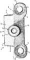
도 1은 본 발명에 따른 척추 스테이플에 대한 사시도이다.1 is a perspective view of a spinal staple according to the present invention.
도 2는 도 1의 상기 척추 스테이플에 대한 정면 입면도이다.FIG. 2 is a front elevational view of the spinal staple of FIG. 1. FIG.
도 3은 상기 스테이플의 밑면을 보여주는 척추 스테이플에 대한 사시도이다.3 is a perspective view of the spinal staple showing the underside of the staple.
도 4는 상기 척추 스테이플의 상면도이다.4 is a top view of the spinal staple.
도 5는 상기 척추 스테이플의 끝단 입면도이다.5 is an end elevation of the spinal staple.
도 6은 끝단 대 끝단 연결 관계로 배열된 본 발명에 따른 두개의 척추 스테이플에 대한 사시도이다.6 is a perspective view of two spinal staples in accordance with the present invention arranged end to end connection.
도 7은 끝단 대 끝단 연결관계로 척추에 설치된 본 발명의 3개의 척추 스테이플에 대한 상면도이다.7 is a top view of the three spinal staples of the present invention installed on the spine in end-to-end connection.
도 8은 두 개의 엔드 플레이트 성장 센터와 삽입 디스크를 연결하도록 두 개의 척추에 고착된 본 발명에 따른 척추 교정 시스템의 부분을 보여주는 입면도이다.8 is an elevational view of a portion of the spinal orthodontic system according to the present invention secured to two vertebrae to connect two end plate growth centers and an insertion disc.
도 9는 본 발명에 따른 상기 척추 스테이플의 또 다른 실시 예를 보여주는 상면도이다.9 is a top view showing still another embodiment of the spinal staple according to the present invention.
도 10은 끝단 대 끝단을 연결하는 관계로 배열된 또 다른 실시예에 따른 2개의 척추 스테이플에 대한 사시도이다.10 is a perspective view of two vertebral staples according to another embodiment arranged in a relationship end to end.
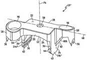
도 11은 또 다른 실시 예에 따른 척추 스테이플을 보여주는 톱 사시도이다.11 is a top perspective view showing a spinal staple according to another embodiment.
도 12는 도 11의 상기 척추 스테이플에 대한 바텀 사시도이다.12 is a bottom perspective view of the spinal staple of FIG. 11.
도 13은 도 11의 상기 척추 스테이플에 대한 바텀 사시도이다.FIG. 13 is a bottom perspective view of the spinal staple of FIG. 11. FIG.
도 14는 도 13의 라인 14-14를 절단한 횡단면도이다.FIG. 14 is a cross-sectional view taken along lines 14-14 of FIG. 13.
도 15는 척추에 설치된 도 11의 척추 스테이플을 보여주는 횡단면도이다.FIG. 15 is a cross sectional view showing the spinal staple of FIG. 11 installed in the spine; FIG.
도 16은 또 다른 실시 예에 따른 척추 스테이플에 대한 사시도이다.16 is a perspective view of a spinal staple according to another embodiment.
도 17은 도 16의 척추 스테이플의 측면 입면도이다.FIG. 17 is a side elevation view of the spinal staple of FIG. 16. FIG.
도 18은 도 17의 척추 스테이플의 끝면도이다.18 is an end view of the spinal staple of FIG. 17.
도 1-6을 참조하면, 본 발명의 실시 예에 따라 구성된 척추 스테이플(10)을 보여준다. 상기 스테이플(10)은 브리지 멤버(12)와, 이격된 한 쌍의 레그(14)와, 좌측 파스너 유지부(16)와, 우측 파스너 유지부(18)와, 그리고 부착부재, 예를 들면 나사산이 있는 포스트(20)를 포함한다. 좌측, 우측, 정면, 후면, 상부, 하부 등과 같이 방향을 포함하는 용어들에 대한 이러한 설명을 통하여 언급이 이루어질 것이지만, 이러한 용어들은 스테이플(10)을 설명하는데 오직 편리만을 위해 사용될 뿐이고 상기 스테이플(10)을 어느 특정 방향을 한정하는 것으로 이해되지 말아야 한다.1-6, a
상기 브리지멤버(12)는 상부 표면 또는 크라운(22)과, 반대편의 하부 표면(24)과, 프런트 사이드(26)와, 반대편의 백 사이드(28)와, 레프트 엔드(30)와, 그리고 반대편의 라이트 엔드(32)를 포함한다. 상기 상부 표면(22)은, 상기 스테이플(10)을 한 끝 단에서 보았을 때 도 5에서 가장 잘 보여주듯이, 상기 레프트 엔드(30)에서 상기 라이트 엔드(32)로 연장되는 방향으로 실질적으로 평면이고, 상기 프런트 사이드(26)에서 상기 백 사이드(28)까지의 방향으로는 볼록하다. 상기 하부 표면(24)은, 도 2, 3에서 가장 잘 보여 주듯이, 상기 레프트 엔드(30)에서 라이트 엔드(32)까지 그리고 상기 프런트 사이드(26)에서 상기 백 사이드(28)까지의 방향으로는 오목하다. 따라서 상기 브리지 멤버(12)는 서로 협동하는 한 쌍의 아치를 한정하고, 제 1 아치는 상기 레프트와 라이트 엔드(30, 32) 사이에 연장되어 있고, 제 2 아치는 상기 프런트 와 백 사이드(26, 28) 사이에 연장되어 있다.The
레프트 및 라이트 레그(14a, 14b)는 상기 레프트 및 라이트 엔드(30, 32)에서 상기 하부 표면(24)으로부터 아래 방향으로 연장되어 있고, 그리고 실질적으로 쐐기 모양이다. 각 레그(14)는 외부 표면(34), 서로 마주 보고 있는 반대 편의 내 부 표면(36), 프런트 표면(38), 그리고 반대편의 백 표면(40)을 가지고 있다. 상기 레그(14)들의 각각은 상기 프런트 표면(38)에서 상기 백 표면(40)까지 측정된 폭을 가지고 있으며, 그 폭은 상기 프런트 사이드(26)에서 상기 백 사이드(28)까지 측정된 상기 브리지 멤버(12)의 폭과 실질적으로 동일하다. 도 1-3에서 보여진 바와 같이, 각 레그(14)의 폭은, 외부 표면(34)에서 내부 표면(36)까지 측정된 것으로서, 각 레그(14)의 두께 보다 몇 배 더 크다. 상기 레그(14)들은 블레이드 에지(43)를 한정하도록 날카롭게 테이퍼 진 각 팁(42)들 방향으로 상기 프런트 표면(38)에서 상기 백 표면(40)까지 약간 좁혀져 있다. 미늘(44)들 각각은 외부, 내부, 프런트, 백 표면들(34, 36, 38, 40)의 각각으로부터 바깥쪽으로 돌출되어 있다.Left and
각 미늘(44)은 대체로 각 팁(42)으로부터 멀어지는 방향으로 마주보고 상기 브리지 멤버(12) 방향으로 대체로 마주하는 유지 표면(45)을 포함하고 있다. 그와 같이, 상기 미늘(44)은 상기 스테이플(10)이 척추와 같은 고정 환경에 일단 위치하면 상기 스테이플(10)의 후진 움직임을 방지하도록 구성된다. 상기 레그들(14)의 상기 내부 표면(36)은, 상기 브리지 멤버(12)의 단면을 통하여 수직으로 연장되어 있는 수직평면(47)으로부터 측정하였을 때 약 10°- 20°의 각도로 서로 멀어지는 방향으로 벌어지거나 또는 각지는 것이 바람직하다. 상기 레그들(14)의 외부 표면(34)은 상기 브리지 멤버(12)에 실질적으로 직각을 이루고 그리고 상기 수직 평면(47)과는 실질적으로 평행하게 아래쪽으로 연장되어 있다.Each
상기 레프트 파스너 유지부(16)는 상기 브리지 멤버 레프트 엔드(30)로부터 바깥쪽으로 연장되어 있다. 상기 라이트 파스너 유지부(18)는 상기 브리지; 멤버 라이트 엔드(32)로부터 바깥쪽으로 연장되어 있다. 상기 파스너 유지부(16, 18)의 각각은 스크류와 같은 파스너를 그 안에 수용하도록 그를 통하여 통로(46)를 한정한다(도 8에 도시). 상기 파스너 유지부(16, 18)와 상기 통로(46)는 파스너(68)를 상기 레그(14)에 실질적으로 평행한 방향으로 안내하도록 형성된다. 또한, 상기 파스너 유지부(16, 18) 각각은, 프런트 및 백 사이드(49, 51)를 포함하며, 그리고 도 6에 도시한 바와 같이 2개의 스테이플(10)이 끝 단 대 끝 단이 서로 인접하는 관계로 배열되어 있을 때 인접하는 끝 단으로부터 연장되어 있는 상기 파스너 유지부(16, 18)들은 서로 사이드 대 사이드가 연결되는 관계가 되도록 조화를 이룬다. 다시 말해, 하나의 스테이플(10)상에 있는 상기 레프트 파스너 유지부(16)는 다른 스테이플(10)의 상기 라이트 파스너 유지부(18)와 옆으로 나란히 놓여진다. 또한, 첫 번째 스테이플(10)의 상기 레프트 파스너 유지부(16)의 백 사이드(51)는 이웃하는 두 번째 스테이플(10)의 상기 라이트 파스너 유지부(18)의 프런트 사이드(49)에 근접하여 마주하는 위치에 놓여진다.The left
도 4에서 볼 수 있듯이, 세로 축(48)은 상기 레프트 엔드(30)에서 상기 라이트 엔드(32)로 상기 스테이플(10)의 중앙을 통하여 연장되어 있다.한 실시 예에서, 상기 레프트 및 라이트 파스너 유지부(16, 18)는 상기 세로 축(48)의 반대 측에 놓여진다.As can be seen in Figure 4, the
또 다른 실시 예에서, 도 9 및 10에서 보여진 바와 같이, 상기 파스너 유지부(16, 18)는 양측 유지부(16, 18)가 상기 세로 축(48)의 동일한 사이드에 놓이도록 상기 브리지 멤버(12)의 반대 끝 단들로부터 연장될 수 있다. 그러한 양자 택일 의 실시 예에서와 같이, 상기 스테이플(10)은 인접하는 스테이플들을 끝 단 대 끝 단으로 180도 회전시킴으로써 끝 단 대 끝 단이 인접하는 방식으로 배열될 수 있다. 그러면, 한 스테이플(10)의 상기 레프트(라이트) 파스너 유지부(16)(18)는 인접하는 다른 스테이플(10)의 레프트(라이트) 파스너 유지부(16)(18)의 옆에 나란히 놓여질 것이다. 또한, 하나의 파스너 유지부(16, 18)의 백 사이드(51)는 두 번째 파스너 유지부(16, 18)의 백 사이드(51)에 근접하여 마주하게 될 것이다.In another embodiment, as shown in FIGS. 9 and 10, the
상기 파스너 유지부(16, 18)의 각각은 리세스를 포함하고 있는데, 예를 들어 파스너(68)의 헤드를 그 안에 수용하도록 형성된 카운터 성크부(50)를 포함한다. 또한 각 파스너 유지부(16, 18)는 또한 아래에 놓인 뼈와 맞물리게 하기 위해 그로부터 아래쪽으로 연장되어 있는 복수개의 제 1 포인트 돌기(54)를 갖는 하부 표면(52)을 포함한다. 제 2 포인트 돌기 또는 미늘(56) 들 또한 상기 파스너 유지부(16, 18)로부터 아래쪽으로 연장되어 있다.Each of the
도 2에 보여진 바와 같이, 상기 포인트 미늘들(56)은 상기 포인트 돌기(54)보다 더 긴 길이를 갖고 그리고 그 중심축에 대하여 상기 스테이플(10)의 회전동작을 저지하도록 상기 유지부(16, 18)의 외부 끝에서 위치되어 있다.As shown in FIG. 2, the
상기 나사산이 있는 포스트(20)는 상기 브리지 멤버(12)의 상부 표면으로부터 상부 쪽으로 연장되어 있다. 상기 나사산이 있는 포스트(20)는 상기 브리지 멤버(12)와 서로 상호 작용하여 상기 브리지 멤버(12)의 하부 표면(24)까지 상기 포스트(20)를 통하여 연장되어 있고 상기 포스트(20)와 동일 축으로 되어 있는 통로(58)를 한정한다. 상기 나사산이 있는 포스트(20)는 추가적인 하드웨어 또는 도 구들이 상기 스테이플(10)에 부착되는 것을 허용하고, 한편으로는 필요 할 경우, 상기 통로(58)는 그를 따라 이동 할 수 있는 가이드 와이어의 통로로 허용한다. 또한, 캐뉼러가 꽂힌 나사산의 포스트(20)는 나사산이 있고 제거 가능한, 캐뉼러가 꽂힌 밀착장치의 부착을 용이하게 한다.The threaded
상기 스테이플(10)은 티타늄, 외과용 스테인레스 스틸, 또는 척추 컬럼의 성장을 저지할 수 있고, 충분한 기계적 피로 특성을 유지하고, 살아 있는 동물의 환경에 충분히 비 반응적인 어떤 다른 물질로 만들어질 수 있다.The staple 10 can be made of titanium, surgical stainless steel, or any other material that can inhibit the growth of spinal columns, maintain sufficient mechanical fatigue properties, and are not sufficiently responsive to the environment of living animals. .
도 7, 8을 참조하면, 상기 스테이플(10)들이 척추 측만 또는 다른 척추 기형을 나타내는 성숙한 또는 성장하는 척추를 갖는 동물의 척추(60)속으로 삽입되어 있다. 상기 스테이플(10)들은 상기 스테이플들(10)이 세로 또는 가로로 배열되어 브리지 하는 것과는 별도로 상기 레그들(14)이 충분히 이격되어 있는 사이즈로 되어 있어, 소정의 크기를 갖고 서로 대면하고 있는 엔드 플레이트 성장 센터(62)들과 그들 사이에 삽입 디스크(64)를 가지고 있는 척추를 연결한다. 상기 스테이플들(10)은 엔드 플레이트 성장 센터(62)들 사이의 중간 부분(66) 속으로 유도되어, 커브진 척추 뼈의 볼록 부분의 척추(60)를 연결하는 것이다. 상기 레그들(14)은 각 척추(60)의 가로 직경 1/2 이하로 연장될 정도의 길이로 되어 있어서 압력이 상기 척추(60)의 일 측으로만 인가되게 하는 것을 확실히 한다. 적당히 위치되면, 상기 레그들(14)은 상기 척추(60)에 충분히 삽입되고, 상기 파스너 유지부(16, 18)의 상기 돌기(54)들과 미늘(56)들은 상기 척추 표면들에 맞물린다. 일단 한 스테이플이 제 위치에 놓여지면, 나산산이 있는 부분, 미늘이 형성된 스테이크 등을 포함하는 스크류들과 같은 파스너(68)들은 파스너 유지부(16, 18)의 통로(46)를 통하여 상기 척추(60)에 삽입된다.7, 8, the
볼록부와 그리고 반대편의 오목부를 한정하는 비정상적인 곡률을 가지며, 한 쌍의 엔드 플레이트 성장 센터(62) 또는 세로의 성장 플레이트를 갖는 그리고 그 사이에 중간 부분(66)을 갖고, 상기 볼록 부에서 오목 부까지 측정되는 방향으로 특정의 가로 직경, 폭, 또는 두께를 갖는 복수개의 세로 방향으로 연결되는 각 척추(60)를 포함하는 성장 척추 뼈에 설치되는 것으로서, 상기 척추 교정 시스템은, 제 1 의 척추(60a)의 중간 부분(66)의 볼록부를 상기 제 1의 척추(60a)의 직경의 1/2 보다 적은 깊이까지 침투하는 제 1 뼈 인게이지 수단 또는 레그(16)와, 제 2 척추(60b)의 중간 부분(66)의 볼록부를 상기 제 2 척추(60b)의 직경의 1/2 보다 적은 깊이까지 침투하는 제 2 뼈 인게이지 수단 또는 레그(14)와, 그리고 상기 제 1 및 제 2 뼈 인게이지 수단을, 예를 들어 견고하게, 연결하는 브리지 멤버(12)를 포함하는 것이 넓게 보여진다(도 8 도시).Having an irregular curvature defining a convex portion and an opposite concave portion, having a pair of end plate growth centers 62 or longitudinal growth plates and having an
따라서 상기 척추 교정 시스템(10)은, 상기 척추 뼈의 오목부상에서 상기 엔드 플레이트 성장 센터(62)의 억제되지 않은 성장을 허용하면서, 상기 척추 뼈의 볼록 부에서 상기 제 1 및 제 2 뼈 인게이지 수단(14) 사이에서 포착된 상기 엔드 플레이트 성장 센터(62)의 성장을 방지 또는 늦춤으로써 상기 성장하는 척추 뼈의 비정상적인 곡률을 교정한다. 척추 뼈가 계속 성장함으로써 상기 척추 뼈의 오목부는 상기 볼록부 보다 상대적으로 빠르게 성장할 것이고 그에 의해 커브 진행이 느리게 되며 상기 척추 뼈의 곡률을 펴는데 가능하게 하여 척추 뼈가 곧게 되는 결과 를 가져올 것이다.The
상기 레그(14)들이 근원적으로 그 사이에서 포착된 상기 엔드 플레이트 성장 센터(62)의 성장을 억제하게 하는 동안, 상기 파스너 유지부(16, 18)와 파스너(68)들은 또한 그들 사이에 포착된 상기 엔드 플레이트 성장 센터(62)의 성장을 억제하는 것에 기여하는 것을 볼 수 있다. 상기 파스너 유지부(16, 18)와 그 협력 파스너(68)들이 상기 엔드 플레이트 성장 센터(62)들의 길이 방향의 성장으로 인해 분산되는 힘을 충분히 저지하도록 되어 있다면 상기 레그(14)들은 생략할 수 있다.The
또 다른 실시 예에 의한 척추 스테이플(10')이 도 11-14에 나타나 있다. 상기 척추 스테이플(10')은 상기에서 이미 언급된 척추 스테이플(10)과 동일한 많은 특징들을 포함하고 있다. 그와 같이, 다음 설명에서, 동일한 도면 부호는 도 1-10의 실시 예에서 설명된 것과 동일한 성분을 말한다.Spinal staples 10 'according to another embodiment are shown in Figures 11-14. The spinal staple 10 'includes many of the same features as the
레프트 및 라이트 레그(14a', 14b')들의 내부 표면들은 뼈 플라우잉을 피하고 한쪽으로 성장하는 것을 늦추는 방식으로 척추(60)의 엔드 플레이트 성장 센터(62) 상에 미치는 압박압력을 분산시키도록 형성된다. 상기 척추 스테이플(10')은 특정 패턴의 압박분산을 유도하도록 형성된다. 상기 엔드 플레이트 성장 센터(62) 내의 압박의 분산 패턴에 영향을 미치는 팩터들은, 상기 스테이플(10)의 다른 구조적 특징과 상기 레그(14')의 상기 척추(60) 내로의 배치와 함께, 상기 레그(10')의 횡단 절단 면적을 함께 한정하는 상기 레그(10')의 길이와 폭이 그에 해당한다. 뼈 플라우잉은 상기 척추(60)의 엔드 플레이트 성장 센터(62) 상의 치료 압력점을 경감하는 경향이 있고, 그에 의해 질병을 진행시킨다.The inner surfaces of the left and
레그(14')의 충분한 횡단면적은 상기 척추(60)에 대하여 적당한 콘택 표면을 확보하게 하여 충분한 엔드 플레이트 성장 센터(62)를 압박하고, 적당한 패턴의 압박 분산을 제공하고, 플라우잉을 방지하고, 그리고 조인트 움직임을 감소시킬 수 있도록 한다. 도 15의 실시 예에서 보여진 바와 같이, 상기 레그(14a', 14b')의 횡단면적(LA)이 상기 제 1 및 제 2 척추(60a, 60b)의 절단면적(VA)의 적어도 10퍼센트가 된다. 한 실시 예에서, 상기 레그(14a', 14b')의 절단면적(LA)은 수직 절단면적(VA)의 10-25 퍼센트 사이에 있다.Sufficient cross-sectional area of the
도 14의 실시 예에서, 프런트 표면(38)로부터 백 표면(40)까지 대략적으로 측정한 것으로서의 각 레그(14')의 폭(LW)은 약 6mm(0.236 인치) 이상이다. 한 실시 예로 상기 폭(LW)은 7 mm(0.276 인치)와 14 mm(0.552 인치)사이에 있다.In the embodiment of FIG. 14, the width LW of each
또한, 상기에서 상세하게 언급한 바와 같이, 상기 내부 표면(36)과 상기 하부 표면(24)의 교차점에서 상기 팁 에지(43)까지 측정되었을 때 각 레그(14')의 길이(LL)는, 예를 들어, 척추 직경의 또는 가로 폭(VW)의 1/2 이상으로 연장되지 않는다(도 15에 도시). 한 실시 예에서, 각 레그(14a', 14b')의 길이(LL)는 각각 제 1 척추(60a) 및 제 2 척추(60b)의 가로 폭의 10 퍼센트 와 40 퍼센트 사이에 있다. 그와 같이, 골격이 미성숙한 어린이의 척추 크기를 근거로 하였을 때, 각 레그(14a', 14b')의 길이(LL)는 24mm(.945 인치) 이하이다. 한 실증적 실시 예로서, 상기 길이(LL)는 3 mm (0.118 인치) 와15 mm (0.59 인치) 사이에 있다.Further, as mentioned in detail above, the length LL of each leg 14 ', as measured from the intersection of the
레그 폭(LW) 대 길이(LL)의 관계는 환자의 필요한 사이즈 또는 스케일을 고려하여 조정될 수 있다. 다시 말해, 큰 사람일수록 더 긴 레그 길이(LL)가 정당할 것이다. 마찬가지로, 상기 폭(LW)은, 환자의 더 큰 역동적 로드(dynamic loads), 근력, 운동력, 척추/육체적 단면적과 관련하여 더 큰 로드(greater load)를 지지할 수 있도록 더 넓어야만 한다. 상기 엔드 플레이트 성장 센터(62)의 단면적이 더 크면 클수록 성장에 의해 발생되는 힘이 더 커진다. 따라서, 레그 폭(LW) 대 레그 길이(LL)의 비는, 환자의 질량과 사이즈의 변화와 나이와 그리고 특히 척추 레벨의 기능으로서 상기 척추(60)의 단면적(VA)을 고려할 때 고려되어야만 한다. 예를 들면, 상부의 흉부 쪽 척추는 하부의 흉부 또는 요 척추의 것보다 훨씬 적고, 그리고 어린이의 척추 몸체는 어른의 그것보다 일반적으로 더 작다. 스테이플 레그 길이(LL) 대 스테이플 레그 폭(LW)의 비는 또한 척추 엔드 플레이트 성장 센터(62)의 코로나 평면(coronal plane)을 가로 질러서 적당한 패턴의 압착 스트레스 기울기를 만들어 내어서, 상기 척추(60)의 스테이플이 된 사이드의 성장을 늦추거나 정지시키고 그리고 상기 척추(60)의 스테이플이 안된 부분에서 억제되지 않은 성장을 허용하는데 중요하다.The relationship of leg width LW to length LL can be adjusted to take into account the required size or scale of the patient. In other words, the larger the leg, the longer the leg length LL would be justified. Likewise, the width LW must be wider to support greater loads in relation to the patient's larger dynamic loads, muscle strength, motor force, spine / physical cross-sectional area. The larger the cross-sectional area of the end
실례적 실시 예에서, 레그 폭(LW) 대 길이(LL)의 비는 약 1/2 보다 더 크다. 다시 말해, 상기 스테이플 레그(14')의 폭(LW)은 적어도 그 길이(LL)의 약 50 퍼센트이다.In an exemplary embodiment, the ratio of leg width LW to length LL is greater than about 1/2. In other words, the width LW of the staple leg 14 'is at least about 50 percent of its length LL.
또한 도 11-13, 16-18을 참조하면, 회전 방지 멤버(80)는 각 스테이플 레그(14')의 외부에 위치되어 있고 이웃하는 파스너 유지부(16, 18)와 인접하고 있다. 특히, 레프트 회전 방지 멤버(80a)는 상기 레프트 파스너 유지부(16)와 상기 레프트 레그(14a) 사이에 연장되어 있고, 라이트 회전 방지 멤버(80b)는 상기 라이 트 파스너 유지부(18)와 상기 라이트 레그(14b)사이에 연장되어 있다. 상기 회전 방지 멤버(80)들은 상기 스테이플 레그(14)의 외부에 위치되어 상기 엔드 플레이트 성장 센터(62) 속으로 절단하지 않고 척추(60)의 뼈 속으로 물고 들어 간다. 상기 레프트 및 라이트 회전 방지 멤버(80a, 80b) 각각은, 상기 제 1 및 제 2 척추(60a, 60b)에 대하여 세로 축(48)을 중심으로 한 상기 레프트 및 라이트 파스너 유지부(16, 18)의 상대적 회전을 감소시키도록 구성되어 있다.11-13 and 16-18, the anti-rotation member 80 is located outside each staple leg 14 'and is adjacent to the neighboring
각 회전 방지 멤버(80)는 고정되는 식으로 상기 척추(60) 뼈에 인게이지 되도록 형성된 하부 에지(82)를 포함하고 있다. 특히, 상기 레프트 회전 방지 멤버(80a)의 하부 에지(82)는 상기 제 1 척추(60a)에 인게이지되도록 형성되어 있고, 상기 라이트 회전 방지 멤버(80b)의 하부 에지(82)는 상기 제 2 척추(60b)에 인게이지 되도록 형성되어 있다. 그와 같이, 상기 하부 에지(82)는 상기 척추 뼈를 파고 들어가도록 날카롭게 될 수 있다. 상기 하부 에지(82)는 예를 들어 상기 세로 축(48)에 평행하게 그리고 상기 레그(14')에서 상기 각 파스너 유지부(16, 18)까지 상 방향으로 연장된다. 특히, 각 회전 방지 멤버(80)는 상기 레그(14')의 외부 표면(34) 중앙 근처에서부터 상기 파스너 유지부(16, 18)까지 연장될 수 있다. 상기 실시 예에서, 상기 회전 방지 멤버(80)는 삼각 미늘처럼 보이는 삼각형의 플레이트를 포함하고 있다. 그러나 상기 회전 방지 멤버(80)는 직사각형 또는 반원 형상과 같은 다른 형상을 한정하는 플레이트로 형성될 수 있다는 것을 알아야 한다.Each anti-rotation member 80 includes a
상기 회전 방지 멤버(80)를 상기 뼈대에 고정하는 것은 상기 스테이플(10 )에 의해 브리지 되어 있는(bridged) 제 1 및 제 2 척추(60a, 60b)의 상대적 회전으 로부터 상기 스테이플(10')을 이동시키는데 필요한 로드(load)를 증가 시킨다. 또한, 상기 회전 방지 멤버(80)는 상기 브리지 멤버(12)에 대한 상기 레그(14')의 벤딩(bending)과 회전상의 골절을 방지하는데 도움을 준다. 상기 회전 방지 멤버(80)는 또한 상기 척추 뼈의 세로 축 및 굽힘-폄 축에 대하여 상기 제 1 및 제 2 척추(60a, 60b) 사이의 상대적 회전을 방지하는데 도움을 줄 수 있다. 상기 회전 방지 멤버(80)는 또한 상기 스테이플(10')의 상기 척추(60)로 상대적으로 움직일 수 있는 가능성을 감소시켜 안정성을 향상시킬 수 있다. 특히 상기 회전 방지 멤버(80)는 상기 척추 뼈의 세로 축과 상기 스테이플(10')의 오프닝(58)을 통하여 연장되어 있는 축(74)을 중심으로 상기 제 1 및 제 2 척추(60a, 60b)에 대하여 상기 스테이플(10')의 회전을 방지하는데 도움을 줄 수 있다.Fixing the anti-rotation member 80 to the armature allows the staple 10 'from the relative rotation of the first and
또 다른 실례적 실시 예로서의 척추 스테이플(100)이 도 16-18에 도시되어 있다. 상기 척추 스테이플(100)은 이미 언급된 척추 스테이플(10, 10')과 동일한 많은 특징들을 포함하고 있다. 그와 같이, 다음 설명에서는 동일한 도면 부호들은 도 1-15의 실시 예에 대하여 상세히 설명된 바와 같이 동일한 성분을 나타낸다.
도 11-15의 척추 스테이플(10')과 도 16-18의 척추 스테이플 사이의 유일한 중요 차이점은 상기 스테이프(100)의 상기 레그들(114a, 114b)이 보이드(void) 또는 스페이스(120)에 의해 분리되어 있는 제 1 및 제 2 부분들(116, 118)을 포함하고 있다는 것이다. 상기 부분들(116, 118)의 팁 에지(122)의 감소된 면적은 상기 레그(114)가 상기 척추(60)의 뼈 속으로 쉽게 삽입되게 하는 결과를 가져온다.The only significant difference between the spinal staple 10 'of FIGS. 11-15 and the spinal staple of FIGS. 16-18 is that the
상기 레그(114)들이 개별의 부분들(116, 118)로 분리된다면, 그의 집합적 크 기는 스테이플(10')의 상기 레그(14')에 대하여 상기에서 상세히 언급한 기준을 실례적으로 만족시켜야만 한다. 특히, 상기 척추(60)에 대하여 적당한 콘택 표면을 확보하기 위하여, 각 레그(114)의 부분들(116, 118) 각각의 집합적 횡 단면적(LA)은 실증적으로 제 1 척추(60a) 및 제 2 척추(60b)의 수직 단면적(VA)의 적어도 10퍼센트, 그리고 한 실례적 실시 예에서 25 퍼센트를 넘지 않는다. 또한 각 레그(114)의 집합적 폭(LW)은 약 6 mm (0.236 인치) 보다 크고, 그리고 실례적으로는 7 mm (0.276 인치) 와 14 mm (0.552 인치) 사이에 있다. 또한 레그(114)의 각 부분들(116, 118)의 길이는 상기 척추의 가로 폭(VW)의 1/2 이상으로 연장되지 않고, 그리고 실례적으로는 24 mm (.945 인치) 보다 작다. 끝으로 각 레그(114)의 집합적 레그 폭(LW)은 실례적으로는 상기 부분들(116, 118)의 평균 길이(LL)의 적어도 약 50 퍼센트이다.If the legs 114 are separated into
상기 상세히 설명된 실시 예들에서는 제 1 및 제 2 척추(60a, 60b) 사이에 연장되는 단일 스테이플(10, 10', 100)을 설명 하고 있지만, 멀티플의 측면으로 이격된 스테이플(10, 10', 100)들도 이용될 수 있다는 것을 알아야만 할 것이다. 그러한 상황에서, 각 척추(60a, 60b) 내의 상기 레그(14, 14', 114)의 집합적 크기는 스테이플(10', 100)의 레그들에 대하여 상기에서 상세히 언급된 그 기준을 만족하여야만 한다.Although the embodiments described in detail above describe a
상기 척추 교정 시스템은 원칙적으로는 미성숙한 또는 성장하고 있는 척추의 비정상적인 측면 곡률을 교정하는 것을 의도하고 있지만, 성숙한 또는 성장하지 않는 척추를 갖는 사람의 척추 교정에 대해서도 또한 이용될 수 있다.The chiropractic system is intended in principle to correct abnormal lateral curvatures of immature or growing vertebrae, but can also be used for chiropractic correction of persons with mature or non-growing vertebrae.
여기서 설명한 장치의 형태들은 본 발명의 바람직한 실시 예에 따라 구성된 것이지만, 본 발명이 그러한 상세한 형태의 장치에 국한된 것이 아니라, 여기 첨부된 청구항들에서 한정되어 있는 발명의 범위를 벗어남이 없이 여기에 변경도 만들어질 수 있다는 것을 이해해야 할 것이다.Although the forms of the devices described herein are constructed in accordance with the preferred embodiments of the present invention, the invention is not limited to such detailed forms of devices, but modifications herein may be made without departing from the scope of the invention as defined in the appended claims. It should be understood that it can be made.
Claims (34)
Translated fromKoreanApplications Claiming Priority (5)
| Application Number | Priority Date | Filing Date | Title |
|---|---|---|---|
| US67988605P | 2005-05-11 | 2005-05-11 | |
| US11/126,782 | 2005-05-11 | ||
| US60/679,886 | 2005-05-11 | ||
| US11/126,782US8021403B2 (en) | 1999-07-07 | 2005-05-11 | Spinal staple system |
| PCT/US2006/018110WO2006122194A1 (en) | 2005-05-11 | 2006-05-11 | Spinal correction system |
Publications (2)
| Publication Number | Publication Date |
|---|---|
| KR20080031176A KR20080031176A (en) | 2008-04-08 |
| KR101272242B1true KR101272242B1 (en) | 2013-06-11 |
Family
ID=37396895
Family Applications (1)
| Application Number | Title | Priority Date | Filing Date |
|---|---|---|---|
| KR1020077028511AExpired - Fee RelatedKR101272242B1 (en) | 2005-05-11 | 2006-05-11 | Spinal correction system |
Country Status (5)
| Country | Link |
|---|---|
| EP (1) | EP1887949A4 (en) |
| KR (1) | KR101272242B1 (en) |
| AU (1) | AU2006244021A1 (en) |
| CA (1) | CA2607921C (en) |
| WO (1) | WO2006122194A1 (en) |
Families Citing this family (12)
| Publication number | Priority date | Publication date | Assignee | Title |
|---|---|---|---|---|
| US8100976B2 (en)* | 2003-04-21 | 2012-01-24 | Rsb Spine Llc | Implant subsidence control |
| EP2135562B1 (en)* | 2008-06-20 | 2015-09-09 | Arthrex, Inc. | Wedged profile plate |
| US9480511B2 (en) | 2009-12-17 | 2016-11-01 | Engage Medical Holdings, Llc | Blade fixation for ankle fusion and arthroplasty |
| EP2651341B1 (en) | 2010-12-16 | 2017-01-04 | Engage Medical Holdings, LLC | Arthroplasty systems and methods |
| US9254130B2 (en) | 2011-11-01 | 2016-02-09 | Hyun Bae | Blade anchor systems for bone fusion |
| US10238382B2 (en)* | 2012-03-26 | 2019-03-26 | Engage Medical Holdings, Llc | Blade anchor for foot and ankle |
| US10842509B2 (en) | 2015-02-05 | 2020-11-24 | The Sydney Children's Hospitals Network (Randwick And Westmead) | Orthopaedic device for correction of deformities in a bone |
| US9649108B2 (en) | 2015-02-24 | 2017-05-16 | Orthovestments, Llc | Orthopedic bone staple with polyaxial compression capability |
| USD851250S1 (en) | 2015-11-19 | 2019-06-11 | Orthovestments, Llc | Bone staple |
| US10376367B2 (en)* | 2015-07-02 | 2019-08-13 | First Ray, LLC | Orthopedic fasteners, instruments and methods |
| US10390955B2 (en) | 2016-09-22 | 2019-08-27 | Engage Medical Holdings, Llc | Bone implants |
| US10456272B2 (en) | 2017-03-03 | 2019-10-29 | Engage Uni Llc | Unicompartmental knee arthroplasty |
Citations (3)
| Publication number | Priority date | Publication date | Assignee | Title |
|---|---|---|---|---|
| US5405391A (en)* | 1993-02-16 | 1995-04-11 | Hednerson; Fraser C. | Fusion stabilization chamber |
| US5502942A (en)* | 1993-09-16 | 1996-04-02 | Prince Corporation | Panel fastener |
| US5662655A (en)* | 1992-07-24 | 1997-09-02 | Laboureau; Jacques Philippe | Osteosynthesis plate-staple |
Family Cites Families (6)
| Publication number | Priority date | Publication date | Assignee | Title |
|---|---|---|---|---|
| GB1551704A (en) | 1975-04-28 | 1979-08-30 | Downs Surgical Ltd | Surgical implant |
| US5395372A (en)* | 1993-09-07 | 1995-03-07 | Danek Medical, Inc. | Spinal strut graft holding staple |
| US5620443A (en)* | 1995-01-25 | 1997-04-15 | Danek Medical, Inc. | Anterior screw-rod connector |
| FR2754702B1 (en)* | 1996-10-18 | 1999-01-08 | Medinov Amp | DEVICE FOR SOLIDARIZING AT LEAST TWO VERTEBRAL BODIES |
| US6299613B1 (en)* | 1999-04-23 | 2001-10-09 | Sdgi Holdings, Inc. | Method for the correction of spinal deformities through vertebral body tethering without fusion |
| EP1370183B1 (en) | 1999-07-07 | 2014-02-19 | Children's Hospital Medical Center | Spinal correction system |
- 2006
- 2006-05-11KRKR1020077028511Apatent/KR101272242B1/ennot_activeExpired - Fee Related
- 2006-05-11CACA2607921Apatent/CA2607921C/ennot_activeExpired - Fee Related
- 2006-05-11EPEP06770186Apatent/EP1887949A4/ennot_activeWithdrawn
- 2006-05-11WOPCT/US2006/018110patent/WO2006122194A1/enactiveApplication Filing
- 2006-05-11AUAU2006244021Apatent/AU2006244021A1/ennot_activeAbandoned
Patent Citations (3)
| Publication number | Priority date | Publication date | Assignee | Title |
|---|---|---|---|---|
| US5662655A (en)* | 1992-07-24 | 1997-09-02 | Laboureau; Jacques Philippe | Osteosynthesis plate-staple |
| US5405391A (en)* | 1993-02-16 | 1995-04-11 | Hednerson; Fraser C. | Fusion stabilization chamber |
| US5502942A (en)* | 1993-09-16 | 1996-04-02 | Prince Corporation | Panel fastener |
Also Published As
| Publication number | Publication date |
|---|---|
| EP1887949A1 (en) | 2008-02-20 |
| EP1887949A4 (en) | 2011-08-24 |
| AU2006244021A1 (en) | 2006-11-16 |
| KR20080031176A (en) | 2008-04-08 |
| CA2607921C (en) | 2013-07-16 |
| CA2607921A1 (en) | 2006-11-16 |
| WO2006122194A1 (en) | 2006-11-16 |
Similar Documents
| Publication | Publication Date | Title |
|---|---|---|
| KR101272242B1 (en) | Spinal correction system | |
| US8021403B2 (en) | Spinal staple system | |
| US5951553A (en) | Methods and apparatus for fusionless treatment of spinal deformities | |
| KR20100087334A (en) | Surgical fixation system and related methods | |
| WO2002076317A1 (en) | Hinged anterior thoracic/lumbar plate | |
| JP6864620B2 (en) | Bone screw | |
| US20170303978A1 (en) | Rigid fixation systems for cardiothoracic fixation | |
| US20040172028A1 (en) | High tibial osteotomy device | |
| JP2017534430A (en) | Laminoplasty spacer | |
| JP3889649B2 (en) | Spinous process spacer | |
| US20060293658A1 (en) | Orthopedic clamps | |
| JP2008539969A (en) | Spine correction system | |
| KR100650208B1 (en) | Spinal Fixation Device | |
| KR100487748B1 (en) | Spinal correction system | |
| MX2007014076A (en) | Spinal correction system | |
| JP5466228B2 (en) | Method and apparatus for securing a band | |
| JP5466228B6 (en) | Method and apparatus for securing a band |
Legal Events
| Date | Code | Title | Description |
|---|---|---|---|
| PA0105 | International application | St.27 status event code:A-0-1-A10-A15-nap-PA0105 | |
| P11-X000 | Amendment of application requested | St.27 status event code:A-2-2-P10-P11-nap-X000 | |
| P13-X000 | Application amended | St.27 status event code:A-2-2-P10-P13-nap-X000 | |
| PG1501 | Laying open of application | St.27 status event code:A-1-1-Q10-Q12-nap-PG1501 | |
| A201 | Request for examination | ||
| PA0201 | Request for examination | St.27 status event code:A-1-2-D10-D11-exm-PA0201 | |
| E902 | Notification of reason for refusal | ||
| PE0902 | Notice of grounds for rejection | St.27 status event code:A-1-2-D10-D21-exm-PE0902 | |
| P11-X000 | Amendment of application requested | St.27 status event code:A-2-2-P10-P11-nap-X000 | |
| P13-X000 | Application amended | St.27 status event code:A-2-2-P10-P13-nap-X000 | |
| E701 | Decision to grant or registration of patent right | ||
| PE0701 | Decision of registration | St.27 status event code:A-1-2-D10-D22-exm-PE0701 | |
| GRNT | Written decision to grant | ||
| PR0701 | Registration of establishment | St.27 status event code:A-2-4-F10-F11-exm-PR0701 | |
| PR1002 | Payment of registration fee | St.27 status event code:A-2-2-U10-U12-oth-PR1002 Fee payment year number:1 | |
| PG1601 | Publication of registration | St.27 status event code:A-4-4-Q10-Q13-nap-PG1601 | |
| FPAY | Annual fee payment | Payment date:20161005 Year of fee payment:4 | |
| PR1001 | Payment of annual fee | St.27 status event code:A-4-4-U10-U11-oth-PR1001 Fee payment year number:4 | |
| LAPS | Lapse due to unpaid annual fee | ||
| PC1903 | Unpaid annual fee | St.27 status event code:A-4-4-U10-U13-oth-PC1903 Not in force date:20170601 Payment event data comment text:Termination Category : DEFAULT_OF_REGISTRATION_FEE | |
| PC1903 | Unpaid annual fee | St.27 status event code:N-4-6-H10-H13-oth-PC1903 Ip right cessation event data comment text:Termination Category : DEFAULT_OF_REGISTRATION_FEE Not in force date:20170601 |