KR101271164B1 - Spinal fixation system instrumentation and method of using same - Google Patents
Spinal fixation system instrumentation and method of using sameDownload PDFInfo
- Publication number
- KR101271164B1 KR101271164B1KR1020087005478AKR20087005478AKR101271164B1KR 101271164 B1KR101271164 B1KR 101271164B1KR 1020087005478 AKR1020087005478 AKR 1020087005478AKR 20087005478 AKR20087005478 AKR 20087005478AKR 101271164 B1KR101271164 B1KR 101271164B1
- Authority
- KR
- South Korea
- Prior art keywords
- sleeve
- rod
- guide
- delete delete
- distal end
- Prior art date
- Legal status (The legal status is an assumption and is not a legal conclusion. Google has not performed a legal analysis and makes no representation as to the accuracy of the status listed.)
- Expired - Fee Related
Links
Images


Classifications
- A—HUMAN NECESSITIES
- A61—MEDICAL OR VETERINARY SCIENCE; HYGIENE
- A61B—DIAGNOSIS; SURGERY; IDENTIFICATION
- A61B17/00—Surgical instruments, devices or methods
- A61B17/56—Surgical instruments or methods for treatment of bones or joints; Devices specially adapted therefor
- A61B17/58—Surgical instruments or methods for treatment of bones or joints; Devices specially adapted therefor for osteosynthesis, e.g. bone plates, screws or setting implements
- A61B17/68—Internal fixation devices, including fasteners and spinal fixators, even if a part thereof projects from the skin
- A61B17/70—Spinal positioners or stabilisers, e.g. stabilisers comprising fluid filler in an implant
- A61B17/7001—Screws or hooks combined with longitudinal elements which do not contact vertebrae
- A61B17/7002—Longitudinal elements, e.g. rods
- A—HUMAN NECESSITIES
- A61—MEDICAL OR VETERINARY SCIENCE; HYGIENE
- A61B—DIAGNOSIS; SURGERY; IDENTIFICATION
- A61B17/00—Surgical instruments, devices or methods
- A61B17/56—Surgical instruments or methods for treatment of bones or joints; Devices specially adapted therefor
- A61B17/58—Surgical instruments or methods for treatment of bones or joints; Devices specially adapted therefor for osteosynthesis, e.g. bone plates, screws or setting implements
- A—HUMAN NECESSITIES
- A61—MEDICAL OR VETERINARY SCIENCE; HYGIENE
- A61B—DIAGNOSIS; SURGERY; IDENTIFICATION
- A61B17/00—Surgical instruments, devices or methods
- A61B17/56—Surgical instruments or methods for treatment of bones or joints; Devices specially adapted therefor
- A—HUMAN NECESSITIES
- A61—MEDICAL OR VETERINARY SCIENCE; HYGIENE
- A61B—DIAGNOSIS; SURGERY; IDENTIFICATION
- A61B17/00—Surgical instruments, devices or methods
- A61B17/56—Surgical instruments or methods for treatment of bones or joints; Devices specially adapted therefor
- A61B17/58—Surgical instruments or methods for treatment of bones or joints; Devices specially adapted therefor for osteosynthesis, e.g. bone plates, screws or setting implements
- A61B17/68—Internal fixation devices, including fasteners and spinal fixators, even if a part thereof projects from the skin
- A61B17/70—Spinal positioners or stabilisers, e.g. stabilisers comprising fluid filler in an implant
- A61B17/7074—Tools specially adapted for spinal fixation operations other than for bone removal or filler handling
- A61B17/7083—Tools for guidance or insertion of tethers, rod-to-anchor connectors, rod-to-rod connectors, or longitudinal elements
- A61B17/7085—Tools for guidance or insertion of tethers, rod-to-anchor connectors, rod-to-rod connectors, or longitudinal elements for insertion of a longitudinal element down one or more hollow screw or hook extensions, i.e. at least a part of the element within an extension has a component of movement parallel to the extension's axis
- A—HUMAN NECESSITIES
- A61—MEDICAL OR VETERINARY SCIENCE; HYGIENE
- A61B—DIAGNOSIS; SURGERY; IDENTIFICATION
- A61B17/00—Surgical instruments, devices or methods
- A61B17/56—Surgical instruments or methods for treatment of bones or joints; Devices specially adapted therefor
- A61B17/58—Surgical instruments or methods for treatment of bones or joints; Devices specially adapted therefor for osteosynthesis, e.g. bone plates, screws or setting implements
- A61B17/68—Internal fixation devices, including fasteners and spinal fixators, even if a part thereof projects from the skin
- A61B17/70—Spinal positioners or stabilisers, e.g. stabilisers comprising fluid filler in an implant
- A61B17/7001—Screws or hooks combined with longitudinal elements which do not contact vertebrae
- A61B17/7002—Longitudinal elements, e.g. rods
- A61B17/7011—Longitudinal element being non-straight, e.g. curved, angled or branched
- A—HUMAN NECESSITIES
- A61—MEDICAL OR VETERINARY SCIENCE; HYGIENE
- A61B—DIAGNOSIS; SURGERY; IDENTIFICATION
- A61B17/00—Surgical instruments, devices or methods
- A61B17/56—Surgical instruments or methods for treatment of bones or joints; Devices specially adapted therefor
- A61B17/58—Surgical instruments or methods for treatment of bones or joints; Devices specially adapted therefor for osteosynthesis, e.g. bone plates, screws or setting implements
- A61B17/68—Internal fixation devices, including fasteners and spinal fixators, even if a part thereof projects from the skin
- A61B17/70—Spinal positioners or stabilisers, e.g. stabilisers comprising fluid filler in an implant
- A61B17/7001—Screws or hooks combined with longitudinal elements which do not contact vertebrae
- A61B17/7035—Screws or hooks, wherein a rod-clamping part and a bone-anchoring part can pivot relative to each other
- A61B17/7037—Screws or hooks, wherein a rod-clamping part and a bone-anchoring part can pivot relative to each other wherein pivoting is blocked when the rod is clamped
Landscapes
- Health & Medical Sciences (AREA)
- Orthopedic Medicine & Surgery (AREA)
- Life Sciences & Earth Sciences (AREA)
- Surgery (AREA)
- Neurology (AREA)
- Heart & Thoracic Surgery (AREA)
- Engineering & Computer Science (AREA)
- Biomedical Technology (AREA)
- Nuclear Medicine, Radiotherapy & Molecular Imaging (AREA)
- Medical Informatics (AREA)
- Molecular Biology (AREA)
- Animal Behavior & Ethology (AREA)
- General Health & Medical Sciences (AREA)
- Public Health (AREA)
- Veterinary Medicine (AREA)
- Surgical Instruments (AREA)
- Prostheses (AREA)
Abstract
Translated fromKoreanDescription
Translated fromKorean본 발명은 척추 고정 방법에 관한 것으로서, 특히 최소 침습 척추 고정 시술을 수행하기 위한 외과적 기계들에 관한 것이다.The present invention relates to a spinal fixation method, and more particularly to surgical machines for performing minimally invasive spinal fixation procedure.
척추 변형을 교정하고 척추 퇴화를 치료하는데 사용되는 척추 고정 시스템은 대체적으로 예를 들어, 인접한 척추뼈의 척추경(pedicle)에 고정되는 일련의 뼈 파스너들로 구성된다. 뼈 파스너들은 하나 또는 그 이상의 가늘고 긴 척추 봉 또는 플레이트에 의해 다른 파스너(fastener)에 상호 연결된다. 이러한 척추 고정 시스템 및 그들의 개별 부품들을 이식하기 위해 척추 영역에 접근하기 위해서, 전통적으로, 개방 접근 수술법(open access surgical techniques)이 채택되고 있다. 이러한 개방 시술들은 대체적으로, 큰 피부 절개부 및 광범위한 조직 수축 및 절개를 수반하기 때문에, 이 모든 것은 상당한 정도의 수술-후 통증 및 회복 시간을 지연시키는 결과를 초래할 수 있다.Spinal fixation systems used to correct spinal deformities and to treat spinal degeneration usually consist of a series of bone fasteners that are secured, for example, to the pedicles of adjacent vertebrae. Bone fasteners are interconnected to other fasteners by one or more elongated spinal rods or plates. In order to access the spinal region for implanting such spinal fixation systems and their individual parts, open access surgical techniques have traditionally been adopted. Since these open procedures generally involve large skin incisions and extensive tissue contractions and incisions, all of these can result in significant post-operative pain and recovery time delays.
보다 최근에, 외과의사들은 척추 고정 시술의 수술-후 효과들을 감소시키는 최초 침습법을 사용하고 있다. 척추옆(paraspinal) 접근법은 최소 침습법의 일 형태이며 척추의 후배부 영역으로 접근하기 위한 근육 찢음 또는 근육 할애(muscle sparing)와 관계된다. 그러한 이러한 기법은 척추와 인접한 조직에 대한 외상을 최소화한다. 근육과 다른 연약한 조직들이 절단되고, 째지고, 벗겨지고 절제되는 개방 접근법과 달리, 척추옆 접근법은 섬유 조직을 따른 근육의 분리 또는 찢음과 관련되어 있다. 척추옆 외과 시술을 수행하기 위해, 중간선(midline) 피부 절개부가 만들어진 후, 양측/단측 근막 절개부(bi/unilateral fascia incision)가 만들어진다. 그 후, 단일의 피부 절개부를 통한 척추까지의 접근을 허용하도록 근육들이 분리된다. 추가적으로, 더 많은 직접 접근을 허용하기 위해 하나 또는 그 이상의 중간선-이탈(off-midline) 피부 절개부들이 만들어질 수 있다.More recently, surgeons have been using the first invasive method of reducing the post-operative effects of spinal fixation procedures. The paraspinal approach is a form of minimally invasive method and involves muscle tearing or muscle sparing to access the posterior region of the spine. Such a technique minimizes trauma to the spine and adjacent tissues. Unlike the open approach, in which muscles and other soft tissues are cut, crushed, peeled, and excised, the lateral approach is associated with the separation or tearing of the muscles along the fibrous tissue. To perform a lateral spinal surgery, a midline skin incision is made, followed by a bi / unilateral fascia incision. The muscles are then separated to allow access to the spine through a single skin incision. Additionally, one or more off-midline skin incisions can be made to allow more direct access.
척추 봉 고정 시스템의 이식은 대체로 적어도 두 단계: (i) 임플란트들(예, 스크류)을 척추에 배치하는 단계 및 (ii) 봉을 임플란트들 사이로 삽입하는 단계를 포함한다. 삽입 시작점, 임플란트들의 궤적 및 임플란트의 크기는 임플란트의 적절한 배치에 중요하다. 대체적으로, 척추 임플란트는 스크류부와 본체부를 구비한다. 스크류부는 척추에 삽입되고 본체부는 대개 척추 봉이 삽입되어 고정되는 채널을 가진다. 봉을 삽입하는 시술은, 스크류 임플란트(들)이 관통 배치되는 절개부와 분리 및 구별되는, 피부의 절개부를 통한 봉의 삽입을 필요로 할 수 있다. 다른 시술들에 있어서, 봉은 스크류 임플란트(들)와 동일한 절개부를 통해 삽입된다.Implantation of the spinal rod fixation system generally includes at least two steps: (i) placing the implants (eg, screws) in the spine and (ii) inserting the rod between the implants. The starting point of insertion, the trajectory of the implant and the size of the implant are important for proper placement of the implant. In general, the spinal implant has a screw portion and a body portion. The screw portion is inserted into the spine and the body portion usually has a channel into which the spinal rod is inserted and fixed. Insertion of the rod may require insertion of the rod through the incision of the skin, which is separate and distinct from the incision through which the screw implant (s) are placed. In other procedures, the rod is inserted through the same incision as the screw implant (s).
인체에 대한 외상을 최소화하고 인체의 다양한 깊이에서 고정된 다수의 임플란트들에 봉을 즉각 연결시키는 최소 침습 척추 임플란트 및 봉 도입 시스템은, 대체로 사용하기 쉽고, 봉이 척추 임플란트들에 삽입될 때 봉의 직접 투시를 향상시킬 수 있는 것이 바람직하다.A minimally invasive spinal implant and rod introduction system that minimizes trauma to the human body and immediately connects the rod to multiple implants fixed at various depths of the human body is generally easy to use and direct viewing of the rod when the rod is inserted into the spinal implants. It is desirable to be able to improve.
본 발명은 고정 시술 수행 방법 및 시술 수행에 사용되는 기계에 관한 것이다. 방사선촬영 이미지는 임플란트들을 수용할 척추뼈를 포함하는 척추로부터 얻어질 수 있다. 방사선촬영 이미지로부터, 하나 또는 그 이상의 삽입 지점들은 환자의 등에 정해질 수 있다. 외과의사는 하나 또는 그 이상의 개구들을 형성하기 위해 환자의 등에 하나 또는 그 이상의 절개부들을 만들 수 있다. 그 후, 외과의사는 피부로부터 척추까지의 절개(부)를 관통하는 통로를 (예, 확장술(dilation) 또는 촉진술(palpation)에 의해) 형성할 수 있다. 전체 시술은 단일의 절개부를 통해 수행될 수 있고 또는 하나의 시술은 다수의 절개부를 이용하여 수행될 수 있다.The present invention relates to a method of performing a fixed procedure and a machine used to perform a procedure. The radiographic image can be obtained from the vertebrae including the vertebrae that will receive the implants. From the radiographic image, one or more insertion points can be set on the patient's back. The surgeon may make one or more incisions on the back of the patient to form one or more openings. The surgeon may then form a passage (eg, by dilation or palpation) through the incision from the skin to the spine. The entire procedure may be performed through a single incision or one procedure may be performed using multiple incisions.
스크류는 절개부를 통해 삽입될 수 있다. 스크류는 뼈 속으로 삽입될 수 있는 샤프트, 및 수술에 적합하도록 샤프트에 연결되고 바람직하게 스크류 샤프트에 대해 움직일 수 있고 바람직하게 스크류 샤프트에 대해 다축적으로 회전할 수 있는 헤드부를 가질 수 있다. 드릴, 송곳, 탐침(probe) 및/또는 스크류드라이버는 스크류를 척추뼈에 삽입하기 위해 사용될 수 있다. 삽입 가이드(insertion guide)는 스크류가 인체에 삽입되기 전 또는 삽입된 후에 스크류, 특히 스크류의 헤드부에 부착될 수 있다. 스크류 대신에, 후크(hook) 또는 다른 고정 장치(fastener device)가 뼈에 부착될 수 있으며, 헤드부 또는 본체부는 움직일 수 있고 후크 또는 다른 파스너에 대해 비스듬하게 될 수 있다.The screw can be inserted through the incision. The screw may have a shaft that can be inserted into the bone, and a head portion connected to the shaft to be suitable for surgery and preferably movable relative to the screw shaft and preferably rotating axially with respect to the screw shaft. Drills, augers, probes and / or screwdrivers may be used to insert the screws into the vertebrae. An insertion guide may be attached to the screw, in particular the head of the screw, before or after the screw is inserted into the human body. Instead of a screw, a hook or other fastener device may be attached to the bone, and the head or body portion may move and be oblique to the hook or other fastener.
일 실시예에 있어서, 삽입 가이드는 관통 구멍을 가진 튜브를 형성하기 위해 서로 연결될 수 있는 제1 및 제2 영역을 가질 수 있다. 제1 영역은 원위단, 근위단, 원위단으로부터 근위단 쪽으로 뻗어 있는 제1 세로 슬롯, 및 적어도 하나의 돌기를 가질 수 있다. 제2 영역은 원위단, 근위단, 원위단으로부터 근위단 쪽으로 뻗어 있는 제2 세로 슬롯, 및 상기 적어도 하나의 돌기를 수납하기 위한 적어도 하나의 리세스를 구비할 수 있다. 조립된 상태에서, 제2 세로 슬롯은 제1 세로 슬롯에 정반대로 대향 될 수 있다. 또한, 제1 및 제2 영역들의 원위단들은 스크류의 헤드부와 결합하는 크기 및 구성일 수 있다. 예를 들어, 제1 및 제2 영역들의 적어도 어느 하나의 원위단은 플랜지(flange) 및 플랜지로부터 구멍 속으로 확장하는 적어도 하나의 보류부(retaining portion)를 가질 수 있다. 플랜지는 스크류와 삽입 가이드가 서로 분리되는 것을 방지하기 위해 스크류의 헤드부에 있는 그루브(groove) 속으로 삽입되는 크기 및 구성일 수 있다. 적어도 하나의 보류부는 스크류에 대한 삽입 가이드의 회전을 방지하기 위해 스크류의 헤드부의 적어도 하나의 표면과 결합하는 크기 및 구성일 수 있다. 또한, 제1 및 제2 영역들의 적어도 하나는 외과의사가 제1 및 제2 영역들을 연결 및/또는 분리하기 위한 파지 표면이 제공될 수 있는 링 부재(ring member)를 구비할 수 있다.In one embodiment, the insertion guide may have first and second regions that can be connected to each other to form a tube with through holes. The first region may have a distal end, a proximal end, a first longitudinal slot extending from the distal end toward the proximal end, and at least one protrusion. The second region may have a distal end, a proximal end, a second longitudinal slot extending from the distal end toward the proximal end, and at least one recess for receiving the at least one protrusion. In the assembled state, the second longitudinal slot may be opposite to the first longitudinal slot. Further, the distal ends of the first and second regions may be sized and configured to engage the head portion of the screw. For example, at least one distal end of the first and second regions may have a flange and at least one retaining portion extending from the flange into the hole. The flange may be sized and configured to be inserted into a groove in the head of the screw to prevent the screw and the insertion guide from being separated from each other. The at least one retention portion may be sized and configured to engage at least one surface of the head portion of the screw to prevent rotation of the insertion guide relative to the screw. In addition, at least one of the first and second regions may have a ring member that may be provided with a gripping surface for the surgeon to connect and / or disconnect the first and second regions.
다른 실시예에 있어서, 삽입 가이드는, 원위단, 근위단, 및 원위단으로부터 근위단까지 뻗어 있는 구멍을 가진 가늘고 긴 본체를 구비할 수 있다. 본체는 삽입 가이드의 원위단으로부터 근위단까지 뻗을 수 있는 제1 및 제2 세로 슬롯들을 가질 수 있다. 제1 및 제2 세로 슬롯들은 서로 정반대로 대향 될 수 있다. 적어도 하나의 슬롯은 제1 및 제2 세로 슬롯 사이에 위치될 수 있다. 그러한 구성은 복수의 아암들을 형성할 수 있다. 아암들은 스크류의 헤드부에 결합할 수 있다. 복수의 아암들은 플랜지 및 플랜지로부터 구멍 속으로 뻗어 있는 적어도 하나의 보류부를 구비할 수 있다. 플랜지는 스크류와 삽입 가이드가 서로 분리되는 것을 방지하기 위해 스크류의 헤드부에 있는 그루브에 삽입되는 크기 및 구성일 수 있다. 적어도 하나의 보류부는 스크류에 대한 삽입 가이드의 회전을 방지하기 위해 스크류의 헤드부의 적어도 하나의 표면과 결합하는 크기 및 구성일 수 있다.In another embodiment, the insertion guide may have an elongated body having a distal end, a proximal end, and a hole extending from the distal end to the proximal end. The body may have first and second longitudinal slots that may extend from the distal end to the proximal end of the insertion guide. The first and second vertical slots may be opposite to each other. At least one slot may be located between the first and second vertical slots. Such a configuration can form a plurality of arms. The arms can engage the head of the screw. The plurality of arms may have a flange and at least one retention portion extending into the hole from the flange. The flange may be of a size and configuration that is inserted into a groove in the head of the screw to prevent the screw and the insertion guide from being separated from each other. The at least one retention portion may be sized and configured to engage at least one surface of the head portion of the screw to prevent rotation of the insertion guide relative to the screw.
또 다른 실시예에 있어서, 삽입 가이드는 내부 슬리브 및 외부 슬리브를 가질 수 있다. 내부 슬리브는 원위단, 근위단, 원위단으로부터 근위단까지 뻗어 있는 구멍, 본체, 본체로부터 확장하는 제1 및 제2 아암들, 아암들 사이에 위치된 제1 및 제2 세로 슬롯들, 및 본체를 따라 위치된 작동 메커니즘을 구비할 수 있다. 외부 슬리브는 원위단, 근위단 및 결합 부재를 구비할 수 있다. 또한, 외부 슬리브는 외부 슬리브의 근위단이 내부 슬리브의 근위단으로부터의 제1 간격에 위치될 수 있는 제1 위치, 및 외부 슬리브의 근위단이 내부 슬리브의 원위단으로부터의 제2 간격에 위치될 수 있는 제2 위치를 가질 수 있으며, 제2 간격은 제1 간격보다 더 크다. 외부 슬리브를 제1 및 제2 위치 사이에서 움직이기 위해 외부 슬리브의 결합 부재와 외부 슬리브가 내부 슬리브의 작동 메커니즘과 결할 수 있도록 외부 슬리브는 내부 슬리브 위에 위치될 수 있다.In yet another embodiment, the insertion guide can have an inner sleeve and an outer sleeve. The inner sleeve includes a distal end, proximal end, a hole extending from the distal end to the proximal end, a body, first and second arms extending from the body, first and second longitudinal slots located between the arms, and the body It may be provided with an operating mechanism positioned along. The outer sleeve may have a distal end, a proximal end and a coupling member. Further, the outer sleeve may be located in a first position where the proximal end of the outer sleeve may be located at a first interval from the proximal end of the inner sleeve, and the proximal end of the outer sleeve may be located at a second interval from the distal end of the inner sleeve. Can have a second position, the second interval being greater than the first interval. The outer sleeve can be positioned above the inner sleeve so that the engagement member of the outer sleeve and the outer sleeve can engage the actuation mechanism of the inner sleeve to move the outer sleeve between the first and second positions.
삽입 가이드를 스크류에 부착하는 하나의 방법은 샤프트 및 관통하는 채널을 가질 수 있는 헤드부를 구비하는 스크류를 제공하는 단계, 본체, 스크류를 수납하기 위해 본체를 관통하는 구멍, 구멍 주위의 레지 및 카운터보어(ledge and counterbore), 및 고정 부재를 구비하는 홀더를 제공하는 단계, 헤드부가 레지에 맞대어 위치되도록 구멍을 통해 스크류의 샤프트를 위치시키는 단계, 고정 부재가 헤드부의 채널 내부에 위치되지 않는 제1 위치와, 고정 부재의 적어도 일 부분이 헤드부의 채널 내부에 위치된 제2 위치 사이에서 고정 부재를 움직이는 단계, 근위단과 원위단을 가진 삽입 가이드를 제공하는 단계, 삽입 가이드의 원위단을 카운터보어에 삽입하는 단계, 및 삽입 가이드의 원위단을 스크류의 헤드부에 결합하는 단계를 포함할 수 있다.One method of attaching an insertion guide to a screw includes providing a screw having a head portion that may have a shaft and a through channel, the body, a hole through the body for receiving the screw, a ledge around the hole and a counterbore (ledge and counterbore), and providing a holder having a fixing member, positioning a shaft of the screw through the hole such that the head portion is positioned against the ledge, a first position in which the fixing member is not located inside the channel of the head portion. And moving the fixing member between a second position where at least a portion of the fixing member is positioned inside the channel of the head portion, providing an insertion guide having a proximal end and a distal end, inserting the distal end of the insertion guide into the counterbore. And engaging the distal end of the insertion guide to the head of the screw.
하나의 방법에 있어서, 스크류를 척추뼈에 삽입하고 삽입 가이드를 스크류에 부착하는 공정은 추가적인, 분리된 절개부들을 통해 반복될 수 있다. 요구되는 숫자의 스크류/삽입 가이드 조립체들이 인체에 위치되면, 슬리브는 가장 바깥쪽 삽입 가이드(예, 연결되어질 척추뼈 그룹의 끝단에 있는 척추뼈에 부착된 삽입 가이드)를 통해 삽입될 수 있다. 슬리브는 원위단, 근위단, 및 원위단으로부터 근위단까지 뻗어 있는 통로를 가진 가늘고 긴 본체일 수 있다. 슬리브는 원위단으로부터 근위단 쪽으로의 제1 간격을 확장할 수 있는 제1 세로 구멍, 및 원위단으로부터 근위단 쪽으로의 제2 간격으로 확장할 수 있으며 제1 세로 구멍에 정반대로 대향된 제2 세로 구멍을 가질 수 있다. 제2 간격은 제1 간격 보다 더 작을 수 있다. 슬리브는 제1 세로 구멍을 비스듬히 교차할 수 있는 제1 구멍과 제2 세로 구멍을 비스듬히 교차할 수 있는 제2 구멍을 가질 수 있다. 일 실시예에 있어서, 제1 구멍은 실질적으로 수직인 각도로 제1 세로 구멍을 교차할 수 있고 제2 구멍은 실질적으로 수직인 각도로 제2 세로 구멍을 교차할 수 있다. 슬리브는 삽입 가이드들과 조직(tissue)을 통한 봉의 이동을 안내하는데 사용될 수 있다.In one method, the process of inserting the screw into the vertebra and attaching the insertion guide to the screw can be repeated through additional, separate incisions. Once the required number of screw / insertion guide assemblies are placed in the human body, the sleeve can be inserted through the outermost insertion guide (eg, an insertion guide attached to the vertebrae at the end of the vertebral group to be connected). The sleeve may be an elongated body having a distal end, proximal end, and a passage extending from the distal end to the proximal end. The sleeve may have a first longitudinal hole capable of extending a first gap from the distal end to the proximal end, and a second longitudinal hole extending at a second interval from the distal end toward the proximal end and opposite the first longitudinal hole. It may have a hole. The second interval may be smaller than the first interval. The sleeve may have a first hole that can cross the first longitudinal hole at an angle and a second hole that can cross the second longitudinal hole at an angle. In one embodiment, the first hole may intersect the first longitudinal hole at a substantially vertical angle and the second hole may intersect the second vertical hole at a substantially vertical angle. The sleeve can be used to guide the movement of the rod through the insertion guides and the tissue.
봉은 슬리브를 통하고, 조직을 통해 스크류들의 헤드부들 속으로 삽입될 수 있다. 일 실시예에 있어서, 외과의사는 봉의 끝단을 잡고, 자신의 손/손가락들을 이용하여 그것을 삽입할 수 있다. 다른 실시예에 있어서, 홀딩 도구(holding instrument)는 봉에 부착될 수 있고 봉을 인체에 삽입하기 위해 사용될 수 있다. 바람직한 실시예에 있어서, 봉은 축, 원위단, 근위단, 및 근위단에 있는 수납부를 구비할 수 있다. 홀딩 도구는 축을 가질 수 있고 외부 부재와 내부 부재를 가질 수 있다. 외부 부재는 원위단, 근위단, 원위단 부근의 한 쌍의 유연한 아암들, 근위단으로부터 원위단까지 뻗어 있는 통로를 구비할 수 있다. 한 쌍의 아암들은 봉의 수납부 내부에 위치될 수 있다. 내부 부재는 원위단, 근위단, 및 근위단에 있는 팁(tip)을 구비할 수 있다. 또한, 내부 부재의 원위단이 한 쌍의 아암들 사이로 삽입될 수 있도록 내부 부재는 외부 부재의 통로를 통한 삽입을 위해 구성될 수 있다. 내부 부재의 원위단이 한 쌍의 아암들 사이로 삽입될 때, 아암들은 각각 외측으로 움직이고 봉의 수납부와 결합할 수 있다. 일 실시예에 있어서, 봉의 수납부는 적어도 하나의 리세스를 가질 수 있고 내부 부재의 팁은 적어도 하나의 리세스 내부에 위치될 수 있다. 이러한 방식에 있어서, 수술자는 봉에 대한 홀딩 도구의 방위를 고정할 수 있다. 예를 들어, 일 방위에 있어서, 봉의 축은 홀딩 도구의 축과 정렬될 수 있고, 다른 방위에 있어서, 봉의 축은 홀딩 도구에 대해 비스듬하게 될 수 있다. 또한, 외부 부재에 대한 내부 부재의 회전이 내부 부재가 외부 부재의 통로 속으로 그리고 밖으로 움직이는 결과를 초래하도록 외부 부재는 내부 부재에 있는 상응하는 나사선과 결합하기 위해 통로 내부의 나사부를 가질 수 있다.The rod may be inserted through the sleeve and through the tissue into the heads of the screws. In one embodiment, the surgeon can hold the end of the rod and insert it using his / her hands / fingers. In another embodiment, a holding instrument can be attached to the rod and used to insert the rod into the human body. In a preferred embodiment, the rod may have a receiving portion at an axis, distal end, proximal end, and proximal end. The holding tool may have an axis and may have an outer member and an inner member. The outer member may have a distal end, a proximal end, a pair of flexible arms near the distal end, and a passage extending from the proximal end to the distal end. The pair of arms can be located inside the receptacle of the rod. The inner member may have a tip at the distal end, the proximal end, and the proximal end. In addition, the inner member can be configured for insertion through the passage of the outer member such that the distal end of the inner member can be inserted between the pair of arms. When the distal end of the inner member is inserted between the pair of arms, the arms can each move outward and engage the receiving portion of the rod. In one embodiment, the receiving portion of the rod may have at least one recess and the tip of the inner member may be located inside the at least one recess. In this manner, the operator can fix the orientation of the holding tool relative to the rod. For example, in one orientation, the axis of the rod may be aligned with the axis of the holding tool, and in another orientation, the axis of the rod may be oblique to the holding tool. In addition, the outer member may have a thread inside the passage to engage the corresponding thread in the inner member such that rotation of the inner member relative to the outer member results in the inner member moving into and out of the passageway of the outer member.
수납부는 하나 또는 그 이상의, 바람직하게 적어도 두 개 또는 그 이상의 구멍들 또는 그루브들을 가질 수 있다. 봉이 홀딩 도구에 대해 회전할 수 있도록 각각의 구멍 또는 그루브는 외부 부재의 아암을 수납할 수 있다. 내부 부재의 원위부가 아암들 사이에 삽입될 때, 아암들은 외측으로 구부러질 수 있고 홀딩 도구에 대해 봉을 붙잡기 위해 구멍들 또는 그루브들과 결합할 수 있다. 일 실시예에 있어서, 각각의 아암은 반구형 모양 부분을 가질 수 있고 그루브들은 아암들의 반구형 모양 부분을 수납하기 위해 그 모양이 반구형일 수 있다.The receiver may have one or more, preferably at least two or more holes or grooves. Each hole or groove may receive an arm of the outer member so that the rod can rotate relative to the holding tool. When the distal portion of the inner member is inserted between the arms, the arms can bend outwardly and engage with holes or grooves to hold the rod against the holding tool. In one embodiment, each arm may have hemispherical portions and the grooves may be hemispherical in shape to receive the hemispherical portions of the arms.
다른 실시예에 있어서, 봉은 축, 원위단, 근위단, 및 근위단에 있는 결합부를 구비할 수 있다. 홀딩 도구는 축을 가질 수 있으며 외부 슬리브 및 내부 슬리브를 포함할 수 있다. 외부 슬리브는 원위단, 근위단 및 관통 통로를 가질 수 있다. 내부 슬리브는 원위단 및 근위단을 가질 수 있으며, 외부 슬리브의 통로 내부에 위치될 수 있다. 내부 슬리브는 가늘고 긴 봉의 결합부와 결합하기 위해 원위단에 있는 부분을 가질 수 있다. 외부 슬리브의 원위단은 봉에 대해 홀딩 도구를 고정하기 위해 내부 슬리브의 원위단 위에서 선택적으로 이동 가능할 수 있다.In other embodiments, the rod may have couplings at the shaft, distal end, proximal end, and proximal end. The holding tool can have a shaft and can include an outer sleeve and an inner sleeve. The outer sleeve can have a distal end, a proximal end and a through passage. The inner sleeve may have a distal end and a proximal end and may be located inside the passageway of the outer sleeve. The inner sleeve may have a portion at the distal end for engaging with the engagement portion of the elongated rod. The distal end of the outer sleeve may be selectively movable over the distal end of the inner sleeve to secure the holding tool with respect to the rod.
몇몇 실시예들에 있어서, 가늘고 긴 봉의 결합부는 구형 모양일 수 있고 내부 슬리브는 결합부를 결합하기 위해 내부 슬리브의 원위단에 있는 복수의 아암들을 가질 수 있다. 대안적으로, 가늘고 긴 봉의 결합부는 복수의 편평한 표면을 가질 수 있으며 내부 슬리브는 내부 슬리브의 원위단에 있는 적어도 두 개의 갈퀴들(prongs)을 가질 수 있으며, 적어도 두 개의 갈퀴들은 각각 적어도 하나의 핀을 가질 수 있다. 적어도 하나의 핀은 가늘고 긴 봉의 결합부의 재질보다 더 경질일 수 있는 재질로 제조된다.In some embodiments, the elongated rod coupling can be spherical in shape and the inner sleeve can have a plurality of arms at the distal end of the inner sleeve to engage the coupling. Alternatively, the elongated rod coupling can have a plurality of flat surfaces and the inner sleeve can have at least two prongs at the distal end of the inner sleeve, each of the at least two rakes each having at least one pin. May have The at least one pin is made of a material that can be harder than the material of the elongate rod coupling.
다른 실시예에 있어서, 내부 슬리브의 원위단에 있는 부분은 적어도 두 개의 갈퀴들을 가질 수 있으며, 각각의 갈퀴는 리세스를 각각 가질 수 있고 결합부는 갈퀴의 리세스 속으로 삽입될 수 있는 적어도 하나의 돌기를 가질 수 있다. 이러한 방식에 있어서, 봉이 홀딩 도구에 대해 회전할 수 있도록 봉은 홀딩 도구에 대해 유지될 수 있다. 내부 슬리브에 대한 외부 슬리브의 회전이 홀딩 도구의 축을 따른 외부 슬리브의 이동을 초래할 수 있도록 내부 슬리브는 외부 슬리브의 통로에 있는 내부 나사산에 의해 결합될 수 있는 외부 나사산을 가질 수 있다. 이러한 방식에 있어서, 외부 슬리브의 원위단은 선택적으로 내부 슬리브의 원위단 위에 위치되거나 그로부터 분리될 수 있다. 외부 슬리브의 원위단이 내부 슬리브의 갈퀴들 위에 위치될 때, 봉은 홀딩 도구에 대해 이동 가능하게 고정될 수 있는(즉, 봉은 홀딩 도구로부터 분리되는 것이 방지됨) 한편 여전히 홀딩 도구에 대해 회전될 수 있다.In another embodiment, the portion at the distal end of the inner sleeve can have at least two rakes, each rake can each have a recess and the at least one engagement portion can be inserted into the rake's recess. May have protrusions. In this manner, the rod can be held relative to the holding tool such that the rod can rotate relative to the holding tool. The inner sleeve can have an outer thread that can be engaged by an inner thread in the passage of the outer sleeve such that rotation of the outer sleeve relative to the inner sleeve can result in movement of the outer sleeve along the axis of the holding tool. In this manner, the distal end of the outer sleeve can optionally be located above or separated from the distal end of the inner sleeve. When the distal end of the outer sleeve is positioned over the rakes of the inner sleeve, the rod can be movably fixed relative to the holding tool (ie the rod is prevented from being separated from the holding tool) while still being rotated relative to the holding tool. have.
홀딩 도구에 대한 봉의 회전을 고정하는 것을 돕기 위해, 홀딩 도구에는 내부 슬리브 내부에 위치되어 그 안에서 이동 가능할 수 있는 가늘고 긴 부재가 마련될 수 있다. 가늘고 긴 부재는 원위단, 근위단, 가이드 부재 및 원위단에 있는 테이퍼부(taper portion)를 구비할 수 있다. 가늘고 긴 부재의 테이퍼부/팁은 홀딩 도구에 대해 봉을 정 위치에 유지하기 위해 봉의 결합부에 있는 수납부에 삽입될 수 있는 포인트를 가질 수 있다. 가늘고 긴 부재는 홀딩 도구의 축을 따라 이동할 수 있지만 내부 슬리브에 대한 축에 대해 회전하지 않도록 가이드 부재는 내부 슬리브의 적어도 하나의 슬롯 속으로 삽입될 수 있다. 외부 슬리브의 원위단이 내부 슬리브의 갈퀴들 위로 더 움직여서, 가늘고 긴 부재가 봉에 결합됨으로써, 홀딩 도구에 대한 봉의 회전 이동을 고정할 수 있도록, 가늘고 긴 부재는 외부 슬리브와 작동 가능하게 연결될 수 있다.To help secure the rotation of the rod relative to the holding tool, the holding tool may be provided with an elongate member that can be positioned inside the movable sleeve and moveable therein. The elongate member may have a taper portion at the distal end, proximal end, guide member and distal end. The tapered portion / tip of the elongate member may have a point that can be inserted into an enclosure in the engagement portion of the rod to hold the rod in position relative to the holding tool. The elongate member may move along the axis of the holding tool but the guide member may be inserted into at least one slot of the inner sleeve so as not to rotate about the axis relative to the inner sleeve. The elongated member can be operably connected with the outer sleeve so that the distal end of the outer sleeve moves further over the rakes of the inner sleeve such that the elongated member is coupled to the rod to secure the rotational movement of the rod relative to the holding tool. .
일 실시예에 있어서, 가늘고 긴 부재가 봉의 결합부와 결합할 때 가늘고 긴 부재의 테이퍼부/팁이 결합 부재를 변형시키고, 파거나 함몰부를 형성할 수 있도록 봉 및/또는 봉의 결합부는 연성 재질(예, 티타늄)로 제조될 수 있고, 가늘고 긴 부재는 경질 재질(예, 스테인리스 스틸)로 제조될 수 있다.In one embodiment, when the elongated member engages with the engagement portion of the rod, the rod and / or engagement portion of the rod and / or engagement of the rod may allow the tapered portion / tip of the elongate member to deform, dig or form a depression. Eg, titanium), and the elongate member may be made of a hard material (eg, stainless steel).
그러한 구성은 무-계단(step-less) 구성을 생성할 수 있다(즉, 봉과 홀딩 도구는 서로에 대해 그 어떤 각도로 위치될 수 있다). 몇몇 실시예에 있어서, 봉의 결합부는 봉의 결합부를 따라 소정의 간격으로 위치된 하나 또는 그 이상의 수납부들 또는 리세스들을 구비할 수 있다. 그러한 구성은 계단 구성을 초래할 수 있다(즉, 봉과 홀딩 도구는 서로에 대해 미리-설정 고정된 각도로 위치될 수 있다). 봉의 결합부가 단지 하나의 리세스를 가지는 경우의 실싱예에 있어서, 가늘고 긴 부재의 테이퍼부/팁이 리세스와 결합할 때, 봉의 축이 홀딩 도구의 축과 정렬될 수 있도록 리세스는 위치될 수 있다.Such a configuration can produce a step-less configuration (ie, the rod and holding tool can be positioned at any angle relative to each other). In some embodiments, the engagement portion of the rod may have one or more receptacles or recesses positioned at predetermined intervals along the engagement portion of the rod. Such a configuration can result in a staircase configuration (ie, the rods and holding tools can be positioned at a preset-set fixed angle with respect to each other). In a sealing example where the engagement portion of the rod has only one recess, when the tapered portion / tip of the elongate member engages the recess, the recess can be positioned so that the axis of the rod can be aligned with the axis of the holding tool. have.
홀딩 도구는 내부 슬리브에 대해 외부 슬리브 및/또는 가늘고 긴 부재를 움직이는데 사용될 수 있는 작동 메커니즘을 더 구비할 수 있다. 작동 메커니즘은 외과의사에게 향상된 파지를 제공하는 파지면을 가질 수 있다. 작동 메커니즘은 제1 치수를 가질 수 있는 제1 통로를 가질 수 있다. 제1 통로는 외부 슬리브의 근위단을 수납하는 크기 및 구성일 수 있다. 작동 메커니즘은 제1 치수보다 작을 수 있는 제2 치수를 가질 수 있는 제2 통로를 구비할 수 있다. 내부 슬리브 및/또는 가늘고 긴 부재는 제2 통로를 통해 위치될 수 있다. 그러한 구성은 작동 메커니즘 내부에 숄더(shoulder)를 형성할 수 있다. 가늘고 긴 부재의 가이드 부재는 작동 메커니즘의 숄더와 외부 슬리브의 근위단 사이에 위치될 수 있다.The holding tool may further comprise an actuation mechanism that can be used to move the outer sleeve and / or the elongate member relative to the inner sleeve. The actuation mechanism may have a gripping surface that provides the surgeon with improved gripping. The actuation mechanism can have a first passageway that can have a first dimension. The first passageway may be sized and configured to receive the proximal end of the outer sleeve. The actuation mechanism may have a second passageway, which may have a second dimension, which may be smaller than the first dimension. The inner sleeve and / or the elongate member can be positioned through the second passageway. Such a configuration can form a shoulder inside the actuation mechanism. The elongate guide member may be located between the shoulder of the actuation mechanism and the proximal end of the outer sleeve.
작동 메커니즘을 외부 슬리브에 유지하기 위해서, 작동 메커니즘의 구멍 내부에 회전 가능하게 수납될 수 있는 유지 부재가 작동 메커니즘에 제공될 수 있다. 유지 부재는 원위단, 근위단, 외면, 근위단에 있는 노브(knob) 및 원위단과 근위단 사이의 노치(notch)를 구비할 수 있다. 외부 슬리브는 유지 부재의 외면을 선택적으로 수납하기 위한 리세스를 가질 수 있다. 유지 부재의 외면이 외부 슬리브의 리세스에 위치될 때, 외부 슬리브는 유지 부재와 작동 메커니즘에 대해 고정될 수 있다(즉, 외부 슬리브는 홀딩 도구의 축을 따른 이동 및/또는 홀딩 도구의 축에 대한 회전으로부터 방지될 수 있다). 유지 부재의 노치가 외부 슬리브의 리세스와 대면할 수 있도록 유지 부재의 노브는 회전될 수 있다. 그러한 방위에 있어서, 외부 슬리브는 유지 부재 및 작동 메커니즘에 대해 이동할 수 있다.In order to hold the actuation mechanism in the outer sleeve, a retaining member may be provided to the actuation mechanism, which may be rotatably received inside the aperture of the actuation mechanism. The retaining member may have a knob at the distal end, the proximal end, the outer surface, the proximal end, and a notch between the distal end and the proximal end. The outer sleeve can have a recess for selectively receiving the outer surface of the retaining member. When the outer surface of the retaining member is positioned in the recess of the outer sleeve, the outer sleeve can be fixed with respect to the retaining member and the actuation mechanism (ie the outer sleeve is moved relative to the axis of the holding tool and / or with respect to the axis of the holding tool). Can be prevented from rotation). The knob of the retaining member can be rotated such that the notch of the retaining member can face the recess of the outer sleeve. In such orientation, the outer sleeve can move relative to the retaining member and the actuation mechanism.
홀딩 부재는 작동 메커니즘 내부에서 유지 부재의 방위를 고정하기 위해 작동 부재를 통해 위치될 수 있다. 홀딩 부재는 유지 부재의 외면이 외부 슬리브의 리세스에 위치될 수 있는(즉, 외부 슬리브가 작동 메커니즘에 대해 정 위치에 록킹될 수 있는) 제1 위치, 및 노치가 리세스와 대면할 수 있는(즉, 외부 슬리브가 작동 메커니즘에 대해 자유롭게 이동할 수 있는) 제2 위치에서 유지 부재를 유지할 수 있다. 특히, 홀딩 부재는 유지 부재의 적어도 하나의 수납부 속으로 삽입될 수 있는 부분을 가질 수 있다.The holding member can be positioned through the operating member to fix the orientation of the retaining member inside the operating mechanism. The holding member has a first position in which the outer surface of the retaining member can be located in the recess of the outer sleeve (ie, the outer sleeve can be locked in place with respect to the actuation mechanism), and the notch can face the recess ( In other words, it is possible to hold the retaining member in a second position where the outer sleeve can freely move relative to the actuation mechanism. In particular, the holding member may have a portion that can be inserted into at least one receiving portion of the retaining member.
봉과 홀딩 도구가 외과의사에 의해 선택되면, 봉은 인체 속으로 삽입될 수 있다. 봉을 인체 속으로 삽입하기 위해, 슬리브의 제1 및 제2 구멍들이 삽입 가이드의 제1 및 제2 세로 슬롯들을 각각 교차함으로써 제1 및 제2 윈도우를 각각 형성할 수 있도록 슬리브는 초기에 삽입 가이드에 위치될 수 있다. 봉은 삽입 가이드와 슬리브가 위치된 절개부를 통하여 삽입될 수 있고 제1 및 제2 윈도우들을 통하고, 조직을 통하며 인접한 삽입 가이드들의 세로 슬롯들을 통과할 수 있다. 보다 상세히, 제1 윈도우는 바람직하게 적어도 부분적으로, 보다 바람직하게, 환자의 등의 피부 위에 완전하게 되어 있다. 봉의 원위 끝단은 환자의 등 위의 제1 윈도우를 통해 슬리브 및 삽입 가이드의 안쪽으로 삽입 및 밀어 넣을 수 있다. 척추 봉의 원위 끝단은 그것이 환자의 근막 아래에 위치된 제2 윈도우에 바람직하게 존재하도록 그리고 근육(예, 근막 아래의 조직층) 속으로 움직이게 더 밀어 넣어질 수 있다. 삽입 가이드의 세로 슬롯들 또는 슬리브의 구멍들/세로 구멍들이 피부 레벨 위에 제1 윈도우를 형성하지 않는 경우의 실시예에 있어서, 봉은 피부와 지방층을 아래로 밀쳐서 방해가 안 되는 곳으로 움직이는데 사용될 수 있다. 피부가 딴 장소로 옮겨진 상태에서, 봉이 바람직하게 환자의 피부 위로부터 삽입 가이드 및 슬리브의 안쪽으로 삽입될 수 있도록 봉은 삽입 가이드의 세로 슬롯 및/또는 슬리브의 구멍들/세로 구멍들을 통해 삽입될 수 있다.Once the rod and holding tool are selected by the surgeon, the rod can be inserted into the human body. In order to insert the rod into the human body, the sleeve is initially inserted so that the first and second holes of the sleeve can respectively form the first and second windows by crossing the first and second longitudinal slots of the insertion guide, respectively. It can be located at. The rod can be inserted through an incision in which the insertion guide and the sleeve are positioned and through the first and second windows, through the tissue and through the longitudinal slots of adjacent insertion guides. In more detail, the first window is preferably at least partially, more preferably completely over the skin of the patient's back. The distal end of the rod can be inserted and pushed into the sleeve and the insertion guide through a first window on the patient's back. The distal end of the spinal rod may be pushed further to move it into the muscle (eg, the tissue layer below the fascia) so that it is preferably present in a second window located below the patient's fascia. In embodiments where the longitudinal slots of the insertion guide or the holes / vertical holes of the sleeve do not form a first window above the skin level, the rod can be used to push the skin and fat layer down and move out of the way have. With the skin removed, the rod can be inserted through the longitudinal slots of the insertion guide and / or the holes / vertical holes of the sleeve so that the rod can be preferably inserted from above the patient's skin into the insertion guide and the sleeve. .
봉이 삽입 가이드들을 통해 삽입될 수 있도록 수술자는 다양한 삽입 가이드들의 세로 슬롯을 정렬하기 위해 삽입 가이드들을 조작할 수 있다. 필요한 숫자의 삽입 가이드들을 통해 봉이 위치되면, 슬리브의 제1 및 제2 세로 구멍들이 삽입 가이드의 제1 및 제2 세로 슬롯들과 정렬할 수 있도록 슬리브는 제2 위치로 회전될 수 있다. 그 후, 봉은 세로 슬롯들과 구멍들 아래로 스크류의 헤드부(예, U-모양의 채널) 속으로 미끄러질 수 있다. 외과의사는 삽입 가이드의 세로 슬롯들 아래로 봉을 미끄러지게 하기 위해 홀딩 도구를 사용할 수 있다. 홀딩 도구는 삽입 가이드가 슬리브를 포함하는 것과 동일한 절개부를 통해 위치될 수 있다. 봉이 스크류들의 헤드부에 위치된 상태에서, 홀딩 도구는 봉으로부터 분리되어 인체로부터 제거될 수 있다. 봉이 앤드 캡(end caps)과 헤드부의 표면(들) 사이에 고정될 수 있도록 엔드 캡들은 삽입 가이드를 통해 삽입될 수 있고 스크류들의 헤드부들에 부착될 수 있다. 봉이 정 위치에 록킹된 후, 삽입 가이드들은 인체로부터 제거될 수 있다. 대안적으로, 엔드 캡들은 삽입 가이드들이 인체로부터 제거된 후 삽입될 수 있다. 삽입 가이드들이 제거된 상태에서, 스크류들과 봉은 고정 시스템을 형성한다. 시술을 완료하기 위해 절개부(들)은 닫혀 질 수 있다.The operator can manipulate the insertion guides to align the longitudinal slots of the various insertion guides so that the rod can be inserted through the insertion guides. Once the rod is positioned through the required number of insertion guides, the sleeve can be rotated to the second position such that the first and second longitudinal holes of the sleeve can align with the first and second longitudinal slots of the insertion guide. The rod can then slide into the head of the screw (eg, a U-shaped channel) under the longitudinal slots and holes. The surgeon may use a holding tool to slide the rod under the longitudinal slots of the insertion guide. The holding tool can be positioned through the same incision that the insertion guide comprises a sleeve. With the rod positioned at the head of the screws, the holding tool can be removed from the rod and removed from the human body. The end caps can be inserted through the insertion guide and attached to the head portions of the screws so that the rod can be secured between the end caps and the surface (s) of the head portion. After the rod is locked in place, the insertion guides can be removed from the human body. Alternatively, the end caps can be inserted after the insertion guides are removed from the human body. With the insertion guides removed, the screws and rods form a fastening system. The incision (s) may be closed to complete the procedure.
고정 방법들 및 관련된 장치들은 아래의 예시적 도면들에 더 상세히 설명된다. 방법과 그 관련 장치들은 이어지는 도면들을 참조함으로써 더 잘 이해될 수 있으며, 유사한 참조부호는 유사한 구성요소들을 나타낸다. 도면들은 단지 방법과 그 관련 장치들을 설명하는 예에 불과하며, 장치들의 구조와 동작 및 특징들은 독립적으로 또는 다른 특징들과 결합하여 사용될 수 있으며 본 발명은 도시된 실시예들에 한정되어서는 아니 된다. 본 명세서에 개시된 도구들, 임플란트들 및 장치들은 뼈 고정 특히, 척추 고정용 키트 또는 시스템으로서 제공될 수 있다.The fixing methods and associated devices are described in more detail in the example figures below. The method and its associated apparatus can be better understood by reference to the following figures, in which like reference characters indicate similar components. The drawings are only examples illustrating the method and related apparatuses, and the structure, operation and features of the apparatuses may be used independently or in combination with other features, and the present invention should not be limited to the illustrated embodiments. . The tools, implants and devices disclosed herein may be provided as a kit or system for bone fixation, in particular spinal fixation.
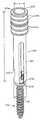
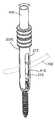
도 1은 본 발명과 함께 사용하기 위한 임플란트의 예시적 실시예의 사시도이다.1 is a perspective view of an exemplary embodiment of an implant for use with the present invention.
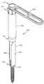
도 2는 척추뼈에 삽입된 도 1의 임플란트를 가진 척추의 사시도이다.FIG. 2 is a perspective view of the spine with the implant of FIG. 1 inserted in the vertebrae; FIG.
도 3A는 도 1의 임플란트에 부착된 본 발명의 삽입 가이드의 예시적 실시예의 사시도이다.3A is a perspective view of an exemplary embodiment of the insertion guide of the present invention attached to the implant of FIG. 1.
도 3B는 도 3A의 삽입 가이드 및 도 1의 임플란트의 절개도이다.3B is a cutaway view of the insertion guide of FIG. 3A and the implant of FIG. 1.
도 4A는 삽입 가이드의 대안적 예시적 실시예의 사시도이다.4A is a perspective view of an alternative exemplary embodiment of an insertion guide.
도 4B는 삽이 가이드의 다른 대안적 예시적 실시예의 절개도이다.4B is a cutaway view of another alternative exemplary embodiment of an insert guide.
도 4C는 제1 위치에서 외부 슬리브를 가진 도 4B의 가이드의 사시도이다.4C is a perspective view of the guide of FIG. 4B with an outer sleeve in a first position.
도 4D는 제2 위치에서 외부 슬리브를 가진 도 4B의 가이드의 사시도이다.4D is a perspective view of the guide of FIG. 4B with an outer sleeve in a second position.
도 4E는 도 4D의 삽입 가이드의 끝단의 사시도이다.4E is a perspective view of the end of the insertion guide of FIG. 4D.
도 4F는 홀더의 예시적 실시예의 사시도이다.4F is a perspective view of an exemplary embodiment of a holder.
도 4G는 도 4B의 삽입 가이드와 함께 사용되도록 된 도 4F의 홀더의 예시적 실시예의 사시도이다.4G is a perspective view of an exemplary embodiment of the holder of FIG. 4F adapted for use with the insertion guide of FIG. 4B.
도 4H는 보이지 않는 특징들을 은선으로 나타내는 삽입 가이드의 대안적인 실시예의 측면도이다.4H is a side view of an alternate embodiment of an insertion guide showing hidden features in hidden lines.
도 4I는 도 4H의 삽입 가이드의 평면도이다.4I is a top view of the insertion guide of FIG. 4H.
도 4J는 몇몇 안보이는 특징들이 은선으로 도시되고 도 4H 및 도 4I의 삽입 가이드의 내부 슬리브의 부분 단면도이다.4J is a partial cross-sectional view of the inner sleeve of the insertion guide of some invisible features shown in hidden lines and FIGS. 4H and 4I.
도 4K는 도 4H 및 도 4I의 삽입 가이드의 칼라(collar)의 단면도이다.4K is a cross-sectional view of the collar of the insertion guide of FIGS. 4H and 4I.
도 4L는 도 4H의 바닥의 단면도이다.4L is a cross-sectional view of the bottom of FIG. 4H.
도 5는 척추에 부착된 도 3A의 조립체의 사시도이다.5 is a perspective view of the assembly of FIG. 3A attached to the spine.
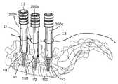
도 6은 척추에 부착된 제2 조립체의 사시도이다.6 is a perspective view of a second assembly attached to the spine;
도 7은 척추에 부착된 제3 조립체의 사시도이다.7 is a perspective view of a third assembly attached to the spine.
도 8A는 본 발명의 가이드 슬리브의 예시적인 실시예의 사시도이다.8A is a perspective view of an exemplary embodiment of the guide sleeve of the present invention.
도 8B는 도 8A의 A-A선을 따른 가이드 슬리브의 단면도이다.FIG. 8B is a cross-sectional view of the guide sleeve along the A-A line in FIG. 8A.
도 8C는 본 발명의 가이드 슬리브의 대안적 예시적인 실시예의 사시도이다.8C is a perspective view of an alternative exemplary embodiment of a guide sleeve of the present invention.
도 9는 본 발명의 고정 봉 및 홀딩 도구의 예시적인 실시예의 사시도이다.9 is a perspective view of an exemplary embodiment of the stationary rod and holding tool of the present invention.
도 9A는 본 발명의 고정 봉 및 홀딩 도구의 대안적 예시적인 실시예의 사시도이다.9A is a perspective view of an alternative exemplary embodiment of the stationary rod and holding tool of the present invention.
도 9B는 본 발명의 고정 봉 및 홀딩 도구의 또 다른 대안적 예시적인 실시예의 사시도이다.9B is a perspective view of another alternative exemplary embodiment of the stationary rod and holding tool of the present invention.
도 10A는 도 9의 고정 봉의 부분 단면 측면도이다.10A is a partial cross-sectional side view of the retaining rod of FIG. 9.
도 10B는 도 10A의 단면의 확대도이다.10B is an enlarged view of the cross section of FIG. 10A.
도 11A는 도 9의 홀딩 도구의 외부 부재의 예시적 실시예의 측면도이다.11A is a side view of an exemplary embodiment of the outer member of the holding tool of FIG. 9.
도 11B는 도 11A의 B-B선을 따른 외부 부재의 단면도이다.FIG. 11B is a cross-sectional view of the outer member along the line B-B in FIG. 11A.
도 12A는 도 9의 홀딩 도구의 내부 부재의 예시적인 실시예의 측면도이다.12A is a side view of an exemplary embodiment of an inner member of the holding tool of FIG. 9.
도 12B는 도 12A의 내부 요소의 끝단의 호가대도이다.12B is a fascia diagram of the end of the inner element of FIG. 12A.
도 13A는 제1 위치에서 홀딩 도구를 가진 본 발명의 고정 봉 및 홀딩 도구의 대안적 예시적인 실시예의 사시도이다.13A is a perspective view of an alternative exemplary embodiment of a holding rod and holding tool of the present invention with a holding tool in a first position.
도 13B는 제2 위치에서 홀딩 도구를 가진 도 13A의 고정 봉 및 홀딩 도구의 사시도이다.FIG. 13B is a perspective view of the fixing rod and holding tool of FIG. 13A with the holding tool in the second position. FIG.
도 14A는 도 13A 및 도 13B의 고정 봉의 예시적인 실시예의 측면도이다.14A is a side view of an exemplary embodiment of the securing rods of FIGS. 13A and 13B.
도 14B는 도 14A의 고정 봉의 평면도이다.14B is a top view of the fixing rod of FIG. 14A.
도 15A는 도 13A 및 도 13B의 홀딩 도구의 측면도이다.15A is a side view of the holding tool of FIGS. 13A and 13B.
도 15B는 도 15A의 C-C선을 따른 홀딩 도구의 단면도이다.15B is a cross-sectional view of the holding tool along line C-C in FIG. 15A.
도 16은 도 15A의 C-C선을 따른 홀딩 도구의 외부 슬리브의 예시적인 실시예의 단면도이다.16 is a cross-sectional view of an exemplary embodiment of an outer sleeve of the holding tool along the line C-C of FIG. 15A.
도 17A는 도 15A 및 도 15B의 홀딩 도구의 내부 슬리브의 예시적인 실시예의 단면도이다.17A is a cross-sectional view of an exemplary embodiment of an inner sleeve of the holding tool of FIGS. 15A and 15B.
도 17B는 도 17A의 내부 슬리브의 평면도이다.17B is a top view of the inner sleeve of FIG. 17A.
도 17C는 도 17B의 내부 슬리브의 끝단부의 확대도이다.17C is an enlarged view of the end of the inner sleeve of FIG. 17B.
도 18은 도 15A 및 도 15B의 홀딩 도구의 가늘고 긴 부재의 예시적인 실시예의 측면도이다.18 is a side view of an exemplary embodiment of the elongated member of the holding tool of FIGS. 15A and 15B.
도 19A는 도 15A의 D-D선을 따른 홀딩 도구의 작동 메커니즘의 예시적인 실시예의 단면도이다.19A is a cross-sectional view of an exemplary embodiment of the actuation mechanism of the holding tool along the line D-D of FIG. 15A.
도 19B는 도 19A의 작동 메커니즘의 유지 부재의 예시적인 실시예의 측면도이다.19B is a side view of an exemplary embodiment of the retaining member of the actuation mechanism of FIG. 19A.
도 19C는 도 19B의 E-E선을 따른 유지 부재의 단면도이다.19C is a sectional view of the retaining member along the E-E line in FIG. 19B.
도 19D는 유지 부재 없이, 도 15A의 D-D선을 따른 작동 메커니즘의 다른 단면도이다.19D is another cross-sectional view of the actuation mechanism along the line D-D in FIG. 15A, without the retaining member.
도 19E는 도 19D의 F-F선을 따른 작동 메커니즘의 단면도이다.19E is a cross sectional view of the actuation mechanism along line F-F in FIG. 19D;
도 20A는 도 13A의 고정 봉 및 홀딩 도구의 부분 단면 평면도이다.20A is a partial cross-sectional top view of the securing rods and holding tool of FIG. 13A.
도 20B는 도 20A의 일부의 확대도이다.20B is an enlarged view of a portion of FIG. 20A.
도 21A는 도 13B의 고정 봉 및 홀딩 도구의 부분 단면 평면도이다.FIG. 21A is a partial cross-sectional top view of the securing rods and holding tool of FIG. 13B.
도 21B는 도 21A의 일부의 확대도이다.21B is an enlarged view of a portion of FIG. 21A.
도 22A는 고정 봉이 도 3A의 제1 조립체를 통해 삽입될 때 도 13B의 고정 봉 및 홀딩 도구의 예시적인 실시예의 사시도이다.22A is a perspective view of an exemplary embodiment of the securing rods and holding tool of FIG. 13B when the securing rods are inserted through the first assembly of FIG. 3A.
도 22B는 조립체 내부에서 제1 방위에서 가이드 슬리브를 가진 도 3A의 조립체의 사시도이다.22B is a perspective view of the assembly of FIG. 3A with a guide sleeve in a first orientation within the assembly.
도 22C는 인체 내부에 위치된 도 22B의 조립체의 단면도이다.FIG. 22C is a cross-sectional view of the assembly of FIG. 22B located inside the human body.
도 23A는 고정 봉이 인체에 삽입될 때 도 13B의 고정 봉 및 홀딩 도구의 예시적인 실시예의 사시도이다.FIG. 23A is a perspective view of an exemplary embodiment of the securing rods and holding tool of FIG. 13B when the securing rods are inserted into a human body. FIG.
도 23B는 조립체 내부에서 제2 방위에 있는 가이드 슬리브를 가진 도 3A의 조립체의 사시도이다.FIG. 23B is a perspective view of the assembly of FIG. 3A with a guide sleeve in a second orientation within the assembly.
도 24는 고정 봉 및 홀딩 도구가 인체 속으로 더 움직일 때 도 13A의 고정 봉 및 홀딩 도구의 사시도이다.24 is a perspective view of the fixation rods and holding tool of FIG. 13A as the fixation rods and holding tool move further into the human body.
도 25는 고정 봉이 도 1의 임플란트들에 위치된 후 도 3A의 척추 및 조립체들의 사시도이다.FIG. 25 is a perspective view of the spine and assemblies of FIG. 3A after the fixation rod is positioned in the implants of FIG. 1. FIG.
도 26은 척추 고정 시스템의 예시적인 실시예의 사시도이다.26 is a perspective view of an exemplary embodiment of a spinal fixation system.
도 27은 고정 봉 및 홀딩 도구의 대안적 예시적인 실시예의 부분 단면도이다.27 is a partial cross-sectional view of an alternative exemplary embodiment of a stationary rod and holding tool.
도 28은 도 27의 홀딩 도구의 외부 슬리브의 부품의 단면도이다.FIG. 28 is a cross sectional view of a part of the outer sleeve of the holding tool of FIG. 27; FIG.
도 29는 보이지 않는 특징들이 은선으로 도시된 도 27의 봉 홀딩 도구의 내부 슬리브의 측면도이다.FIG. 29 is a side view of the inner sleeve of the rod holding tool of FIG. 27 with invisible features shown in hidden lines. FIG.
도 30은 도 29의 내부 슬리브의 부분 단면 평면도이다.30 is a partial cross-sectional top view of the inner sleeve of FIG. 29.
도 31은 도 27의 봉 홀딩 도구의 가늘고 긴 부재의 측면도이다.FIG. 31 is a side view of the elongated member of the rod holding tool of FIG. 27.
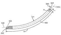
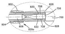
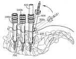
본 발명의 척추 고정 방법은 복수의 임플란트들(예, 스크류 100), 복수의 삽입 가이드들(insertion guide) 200,300,350,350', 슬리브(sleeve) 400,416, 봉(rod)(예, 고정 봉 500,550,570,700) 및 홀딩 도구(holding instrument) 600,650,670,800,900을 포함하는 다양한 장치를 사용하여 수행된다. 그러나, 당업자들은 본 발명의 다양한 구성요소들에 가해질 수 있는 수많은 변형물들과 대체물들을 인식할 수 있음을 이해해야 한다. 또한, 본 명세서에 개시된 기계들은 척추 고정 시술들과 관련하여 사용되고 있는 것이지만, 당업자는 그러한 장치들이 고정 시술을 수행하기 위해 인체의 그 어떤 다른 부위(예, 장 뼈)에도 사용될 수 있음을 잘 이해할 것이다. 따라서, 위치는 그 어떤 방식으로 제한을 의도하는 것이 아니다. 또한, 장치들은 단독적으로 또는 본 명세서에 개시된 다른 기계들 또는 본 명세서에 개시되지 않는 다른 기계들과 결합하여 사용될 수 있으며, 다양한 임플란트 들과 함께 사용될 수 있다. 그리고, 본 명세서에서 논의된 시술들은 후배부 접근법(posterior approach)을 사용하여 수행되지만, 당업자라면 그 방법과 장치는 그 어떤 형태의 접근법(예, 후-측방, 측방, 전방, 전-측방)을 위해 개조될 수 있음을 이해할 것이다.The spinal fixation method of the present invention comprises a plurality of implants (e.g. screws 100), a plurality of insertion guides 200,300,350,350 ', sleeves 400,416, rods (e.g. fixation rods 500,550,570,700) and holding tools (holding instrument) Performed using a variety of devices, including 600,650,670,800,900. However, those skilled in the art should understand that numerous modifications and substitutions may be made to the various components of the present invention. Also, while the machines disclosed herein are used in connection with spinal fixation procedures, those skilled in the art will appreciate that such devices may be used on any other part of the human body (eg, intestinal bone) to perform a fixation procedure. . Thus, location is not intended to be limiting in any way. In addition, the devices may be used alone or in combination with other machines disclosed herein or other machines not disclosed herein, and may be used with a variety of implants. And, while the procedures discussed herein are performed using a posterior approach, those skilled in the art will appreciate that any method and apparatus may employ any form of approach (e.g., posterior-lateral, lateral, anterior, anterior-lateral). It will be appreciated that it may be retrofitted.
방사선촬영 이미지는, 예를 들어, 척추경 나사들 및 고정 척추 봉들과 같은 임플란트들을 수납하는 척추뼈를 포함하는 척추로부터 취해질 수 있다. 방사선촬영 이미지로부터, 하나 또는 그 이상의 삽입 지점들은 환자의 등에 정해질 수 있다. 외과의사는 개구를 형성하기 위해 환자의 등에 절개부(incision)를 만들 수 있다. 절개부는, 예를 들어, 약 1cm 내지 약 10cm 사이, 보다 바람직하게, 약 1.5cm 내지 약 5cm 사이의 길이를 가질 수 있다. 보다 작은 절개부는 각각의 삽입 가이드(insertion guide)가 그 자신의 절개부를 통해 삽입될 수 있는 곳에 사용될 수 있고, 보다 큰 절개부는 하나보다 많은 삽입 가이드가 단일의 절개부를 통해 삽입될 수 있는 곳에 사용될 수 있다. 바람직하게, 임플란트들은 척추경들(pedicles) 속으로 삽입되거나 척추의 추궁판(laminae)에 부착되고, 따라서, 절개부들은 중앙 척추 극돌기(spinous process)로부터 예를 들어, 약 15 내지 약 35mm 가량 옵셋된다. 한 세트의 임플란트들은 척추 극돌기의 양측에 사용될 수 있다.A radiographic image can be taken from the spine comprising the vertebrae, for example, receiving implants such as pedicle screws and fixed spinal rods. From the radiographic image, one or more insertion points can be set on the patient's back. The surgeon may make an incision in the patient's back to form an opening. The incision may, for example, have a length between about 1 cm and about 10 cm, more preferably between about 1.5 cm and about 5 cm. Smaller incisions can be used where each insertion guide can be inserted through its own incision, and larger incisions can be used where more than one insertion guide can be inserted through a single incision. have. Preferably, the implants are inserted into the pedicles or attached to the laminae of the spine, so that the incisions are offset, for example, from about 15 to about 35 mm from the central spinal process. do. A set of implants can be used on both sides of the spinal spine.
그 후, 가이드 와이어(미도시)는 절개부를 통해 척추뼈 속으로 삽입될 수 있다. 가이드 와이어가 척추뼈(예, 척추뼈의 척추경 속으로)에 부착될 수 있도록 외과수술용 망치(mallet) 또는 다른 충격 도구(미도시)는 가이드 와이어를 타격하기 위해 사용될 수 있다. 가이드 와이어는 다양한 장치 및/또는 임플란트를 환자 속으 로 그리고 척추 쪽으로 안내하기 위해 사용될 수 있다. 예를 들어, 가이드 와이어는 확장기(dilators), 삽입 가이드, 드릴 비트, 스크류드라이버, 및/또는 임플란트(예, 뼈 스크류)를 척추의 위치로 안내하는데 사용될 수 있다. 그러나, 본 명세서에서 설명된 그 어떤 장치들은 가이드 와이어 및/또는 가이드 와이어를 사용하지 않고 형성될 수 있는 척추를 향하는 통로들을 사용하지 않고 환자 속으로 삽입될 수 있음을 주목해야 한다.The guide wire (not shown) can then be inserted into the vertebrae through the incision. Surgical mallets or other impact tools (not shown) may be used to strike the guide wires such that the guide wires may be attached to the vertebrae (eg, into the pedicle of the vertebrae). Guide wires can be used to guide various devices and / or implants into and into the spine. For example, guide wires may be used to guide dilators, insertion guides, drill bits, screwdrivers, and / or implants (eg, bone screws) to the location of the spine. However, it should be noted that some of the devices described herein can be inserted into a patient without the use of guide wires and / or passages towards the spine that can be formed without using the guide wires.
일 방법에 있어서, 절개부는 예를 들어, 순차 확장술(sequential dilation)에 의해 확장될 수 있다. 가이드 와이어가 먼저 절개부를 통해 삽입되면, 확장기들은 가이드 와이어 위로 삽입될 수 있다. 가이드 와이어가 사용되지 않으면, 하나 또는 그 이상의 확장기들이 피부 및 조식을 통해 직접 삽입될 수 있다. 확장은, 조직을 통해(예, 근육을 통해), 조직 분절들(예, 근육 조각들) 사이에서, 또는 조직과 척추 사이에서 수행될 수 있다. 절개부의 확장은 그 어떤 수의 장치들을 사용하여 수행될 수 있음을 당업자들은 이해할 것이다. 다른 방법에 있어서, 조직을 통하여, 조직 영역들 사이(예, 뭇갈래근(multifidus muscle)과 longisimus 근육 사이)에서 또는 조직과 척추 사이에서 틈새 또는 공간을 생성하기 위해 근육과 조직을 확장 또는 해부하기 위해서, 외과의사는 절개부를 통해 그의 손가락(들)을 하부의 조직 속으로 삽입할 수 있다. 이러한 방식에 있어서, 외과의사는 척추뼈 및/또는 촉수 해부적 표지(palpate anatomical landmark)(예, 척추후 관절(facet joint))에 통로를 생성할 수 있다. 상술한 방법들은 척추에 추가적인 통로들을 생성하기 위해 반복될 수 있다. 보다 작은 구멍은 각각의 삽입 가이드가 그 자신의 구멍을 통해 삽입될 수 있는 경우에 사용될 수 있고, 보다 큰 절개부(들)은 하나보다 많은 삽입 가이드가 동일한 구멍을 통해 삽입될 수 있는 경우에 사용될 수 있다. 각각의 스크류 및 삽입 가이드가 단일의 구멍을 통해 삽입되는 실시예에 있어서, 통로의 구멍은, 예를 들어 약 0.5cm 내지 약 3cm 사이, 보다 바람직하게, 약 1cm 내지 약 2cm 사이의 직경을 가질 수 있다. 구멍은 예를 들어, 타원형, 원형, 계란-형, 정사각형, 직사각형, 다각형 또는 다른 모양들과 같이 그 어떤 모양일 수 있음을 유의해야 한다.In one method, the incision may be expanded by, for example, sequential dilation. If the guide wire is first inserted through the incision, the dilators can be inserted over the guide wire. If no guide wire is used, one or more dilators may be inserted directly through the skin and breakfast. Expansion may be performed through tissue (eg through muscle), between tissue segments (eg muscle fragments), or between tissue and the spine. Those skilled in the art will understand that expansion of the incision can be performed using any number of devices. In another method, expanding or dissecting muscle and tissue through tissue, to create a gap or space between tissue regions (eg, between multifidus muscle and longisimus muscle) or between tissue and spine. To do this, the surgeon can insert his finger (s) into the underlying tissue through the incision. In this manner, the surgeon may create passages in the vertebrae and / or tentacle anatomical landmarks (eg, facet joints). The methods described above can be repeated to create additional passages in the spine. Smaller holes can be used where each insertion guide can be inserted through its own hole, and larger incision (s) can be used when more than one insertion guide can be inserted through the same hole. Can be. In embodiments in which each screw and insertion guide is inserted through a single hole, the aperture of the passageway may have a diameter, for example between about 0.5 cm and about 3 cm, more preferably between about 1 cm and about 2 cm. have. It should be noted that the hole may be any shape, for example oval, circular, egg-shaped, square, rectangular, polygonal or other shapes.
몇몇 방법들에 있어서, 완전한 시술은 단일의 확장된 통로를 통해 수행된다. 예를 들어, 시술은 그 전체 내용이 인용에 의해 본 명세서에 합체되고, 2004. 8. 13.자로 출원된 미국 특허 출원 번호 제10/917,560호의 "Multi-Blade Retractor"에 개시된 바와 같이, 인체에 삽입된 후 확장될 수 있는, 캐뉼라 또는 견인기(retractor)를 통해 수행될 수 있다. 전체 시술이 단일의 절개부를 통해 수행될 수 있는 경우의 방법에 있어서, 절개부가 완전히 확장된 후, 캐뉼라, 견인기 또는 삽입 가이드는 확장기 위로 또는 직접적으로 통로 속으로 인체에 배치될 수 있다. 그러한 방법들에 있어서, 통로의 구멍은 예를 들어, 약 1.0cm 내지 약 12cm 사이, 보다 바람직하게, 약 3cm 내지 약 8cm 사이의 직경을 가질 수 있다.In some methods, the complete procedure is performed through a single extended passage. For example, a procedure may be performed on a human body, as disclosed in "Multi-Blade Retractor" of US Patent Application No. 10 / 917,560, filed August 13, 2004, the entire contents of which are incorporated herein by reference. It can be performed via a cannula or a retractor, which can be expanded after insertion. In the case where the entire procedure can be performed through a single incision, after the incision is fully extended, the cannula, retractor or insertion guide may be placed in the human body above or directly into the passageway. In such methods, the aperture of the passageway can have a diameter, for example, between about 1.0 cm and about 12 cm, more preferably between about 3 cm and about 8 cm.
척추에 통로가 생성되고 아면, 드린, 송곳 및/또는 탐침은 하나 또는 그 이상의 척추뼈에 개구를 생성하기 위해 사용된다. 임플란트(예, 도 1의 스크류 100)는 통로를 통해 통과할 수 있고 스크류드라이버를 이용하여 척추뼈의 개구 속으로 삽입될 수 있다. 예를 들어, 스크류 100은 두 개 또는 그 이상의 인접한 척추뼈의 각각의 척추경 속으로 삽입될 수 있다. 다른 실시예들에 있어서, 스크류 100은 자체적 나사 형성 및/또는 자체적 탭핑(tapping)일 수 있으므로, 탭(만약 사용되는 경우)은 불필요할 수 있고 스크류 100은 예를 들어, 스크류드라이버를 사용하여 척추뼈 속으로 직접 삽입될 수 있다.Once a passage is created in the spine and known, the drill, awl and / or probe are used to create an opening in one or more vertebrae. The implant (eg, screw 100 of FIG. 1) may pass through the passage and may be inserted into the opening of the vertebrae using a screwdriver. For example, screw 100 may be inserted into each pedicle of two or more adjacent vertebrae. In other embodiments, the
스크류 100은 샤프트부 102 및 샤프트부 102에 작동 가능하게 연결된 헤드부 104를 구비할 수 있다. 샤프트부 102에는 나사가 형성될 수 있다. 스크류 100은 다축적일 수 있으므로 헤드부 104는 분절적(articulate)일 수 있고 샤프트부 102에 대해 회전 가능할 수 있다(예, 헤드부 104는 하나 이상의 축에 대해 움직일 수 있고; 다축 스크류). 대안적으로, 샤프트부 102 및 헤드부 104는 서로에 대해 고정될 수 있다. 샤프트부 102는 그곳을 관통하는 보어 106을 가질 수 있으므로 스크류 100은 가이드 와이어 위에 위치될 수 있다. 헤드부 104는 U-모양일 수 있고 고정 봉(fixation rod)을 수납할 수 있는 채널 108을 가질 수 있다. 헤드부 104는 앤드 캡 150(도 26)을 수납하기 위한 내부 나사산 110을 가질 수 있으므로, 고정 봉은 앤드 캡과 채널 110의 표면 112a,112b 사이의 채널 108에 유지될 수 있다. 다른 앤드 캡들 및 헤드부에 대한 척추 봉의 유지 및/또는 샤프트부의 록킹 수단이 구현될 수 있다. 또한, 그루브 또는 리세스 114는 헤드 104와 통합될 수 있으므로 삽입 가이드가 그곳에 부착될 수 있다. 그러나, 스크류가 고정 봉을 바람직하게 수납하도록 구성된 채널을 수용하는 봉에 통합되거나 부착될 수 있는 한 그 어떤 스크류가 사용될 수 있음을 예측할 수 있다. 스크류 100이 척추뼈에 위치되면, 가이드 와이어는, 만약 존재하면, 제거될 수 있다. 임플란트는 스크류, 및 바람직하게 다축 스 크류를 참조하여 설명되었지만, 임플란트는 후크 또는 다른 고정 장치일 수 있으며, 후크와 다른 파스너(fastener)는 뼈 부착 요소에 대해 다축적으로 회전 또는 각을 형성할 수 있는 헤드 또는 본체를 가질 수도 있고 그렇지 않을 수 있음을 유의해야 한다.The
샤프트부 102와 헤드부 104는 단일 유니트로서 본체에 삽입될 수 있는 한편, 다른 실시예들에 있어서, 샤프트부 102와 헤드부 104는 분리되게 삽입될 수 있다. 그러한 실시예에 있어서, 샤프트부 102는 척추뼈 속으로 삽입될 수 있다. 그 후, 헤드부 104는 샤프트에 부착될 수 있다. 그러한 실시예에 있어서, 헤드부 104는 삽입 가이드 200,300,350,350' 및/또는 다른 도구에 부착될 수 있으므로, 헤드부 104와 삽입 가이드 200,300,350,350' 및/또는 다른 도구는 단일 유니트 또는 조립체로서 본체에 삽입될 수 있다. 헤드부 104에 힘을 가하기 위한 지레 장치(leverage)를 외과의사에게 제공하기 위해, 헤드부 104는 삽입 가이드 200,300,350,350' 및/또는 다른 도구(예, 푸셔(pusher))를 사용하여 샤프트부 102에 부착 및/또는 스냅 결합될 수 있다.The
또한, 스크류 100은 환자의 인체에 삽입되기 전에 삽입 가이드 200,300,350,350'에 부착될 수 있으므로 스크류 및 삽입 가이드 200,300,350,350'은 단일의 유니트로서 환자에 삽입될 수 있다. 그 후, 스크류를 척추뼈에 삽입하기 위해 도구(예, 스크류드라이버)는 삽입 가이드 200,300,350,350'을 통해 삽입될 수 있다. 또한, 다른 실시예에 있어서, 삽입 가이드 200,300,350,350'은 스크류 100 앞의 인체에 위치될 수 있다. 하나 또는 그 이상의 도구들(예, 드릴, 송곳, 탐침) 은 척추뼈에 구멍(예, 척추뼈의 척추경에 있는 구멍)을 생성하기 위해 삽입 가이드 200,300,350,350'을 통해 삽입될 수 있다. 스크류 100은 그 후 삽입 가이드 200,300,350,350' 아래로 삽입될 수 있고, 삽입 가이드 200,300,350,350'의 원위단에 부착되어 스크류드라이버를 사용하여 척추뼈에 삽입될 수 있다. 다른 시술들에 있어서, 스크류드라이버(미도시)는 삽입 가이드 200,300,350,350' 내부에 위치될 수 있고 스크류 100과 결합할 수 있으므로, 스크류 100, 삽입 가이드 200,300,350,350' 및 스크류드라이버는 단일의 유니트로서 인체에 삽입될 수 있다. 스크류 100이 척추뼈에 삽입되면, 스크류드라이버는 제거되고, 스크류 100과 삽입 가이드 200,300,350,350'을 인체에 위치에 남겨 둘 수 있다. 가이드 와이어를 사용하는 실시예에 있어서, 스크류 100, 삽입 가이드 200,300,350,350' 및/또는 다른 도구(들)(예, 드릴, 스크류드라이버)는 가이드 와이어 위로 척추뼈에 삽입될 수 있다.In addition, the
시술에 사용될 수 있는 삽입 가이드(예, 삽입 가이드 200,300,350,350')의 형태는 예를 들어, 외과의사의 선호도, 인체의 골격 및/또는 외과 시술의 요구조건들에 의존한다. 고정 봉이 그곳을 통해 삽입될 수 있고 삽입 가이드가 스크류 100 또는 다른 임플란트와 작동 가능하게 연결될 수 있는 한, 삽입 가이드의 그 어떤 구성도 사용될 수 있음을 당업자는 이해할 것이다.The type of insertion guide that can be used for the procedure (eg, insertion guide 200,300,350,350 ') depends, for example, on the preferences of the surgeon, the skeleton of the human body and / or the requirements of the surgical procedure. Those skilled in the art will appreciate that any configuration of the insertion guide can be used, as long as the retaining rod can be inserted therein and the insertion guide can be operatively connected with the
일 실시예에 있어서, 삽입 가이드는 그 어떤 추가적 도구들을 사용하지 않고 통로를 통해 환자에 직접 삽입될 수 있다. 따라서, 삽입 가이드는 개구를 확장/견인하는 기능을 수행할 수 있다. 또한, 삽입 가이드는 스크류 100의 헤드부 104를 움직이는데(예, 회전, 각지게 하는데) 사용될 수 있으므로, 수술자는 인접한 척추뼈에 삽입될 수 있는 다수의 스크류들 100의 채널을 정렬할 수 있다. 이러한 방식에 있어서, 고정 봉은 인접한 척추뼈에 위치된 스크류들 100 속으로 삽입될 수 있다.In one embodiment, the insertion guide can be inserted directly into the patient through the passageway without using any additional tools. Thus, the insertion guide can perform the function of expanding / towing the opening. In addition, the insertion guide can be used to move (eg, rotate, angle) the
삽입 가이드 200,300,350,350'은 외과의사가 헤드부 104의 방위를 직접적으로 가시화하는 것을 허용할 수 있다. 그러한 바와 같이, 외과의사는 채널 108에서 헤드부 104의 방위를 확인할 수 있다. 삽입 가이드 200,300,350,350' 내부에서 및/또는 외과 수술 부위 속에서 가시화할 수 있는 외과의사의 능력을 더 향상시키기 위하여, 삽입 가이드는 그것과 함께 일체화되거나 그곳에 부착된 광원(미도시)을 가질 수 있다. 나아가, 삽입 가이드는 외과의사가 삽입 가이드 200,300,350,350' 안을 들여다 보는 것을 방해하거나 및/또는 수술 부위의 시야를 방해할 수 있는, 수액 및/또는 조직을 제거하기 위한 흡입-관주(suction-irrigation) 시스템(미도시)을 가질 수 있다. 현미경 또는 내시경(미도시)은 수술 부위의 향상된 시야를 제공하기 위해 삽입 가이드 200,300,350,350'에 부착될 수 있다. 또한, 시술이 삽입 가이드 200,300,350,350'의 안정을 필요로 하는 경우, 삽입 가이드 200,300,350,350'은 예를 들어, 수술대에 부착될 수 있고 삽입 가이드 200,300,350,350'을 환자에 대해 정 위치로 유지할 수 있음으로써, 수술하는 동안 외과의사 또는 간호사가 삽입 가이드 200,300,350,350'를 유지할 필요성을 제거하는, 테이블 마운트에 부착될 수 있다.Insertion guides 200, 300, 350, 350 ′ may allow the surgeon to directly visualize the orientation of the
삽입 가이드 200,300,350,350' 및 그 부품들은 예를 들어, 금속, 세라믹, 플 라스틱, 고무, 물질의 조합 또는 복합 재료로 제작될 수 있다. 예를 들어, 삽입 가이드 200,300,350,350' 및 그 부품들은 스테인리스 스틸, 티타늄, 알루미늄, 합금, 카본 섬유 복합재, 또는 폴리머(예, 폴리비닐 클로라이드(PVC), 폴리에틸렌, 다양한 종류의 폴리에스테르, 폴리카보네이트, 테프론 코팅 금속, 폴리에테르에테르 케톤(PEEK), 또는 초 고분자 중량 폴리에틸렌(UHMWPE))으로부터 제조될 수 있다. 삽입 가이드 200,300,350,350'은 비-광택 윤활 코팅을 가질 수 있으며 및/또는 방사선투과성 또는 방사선불투과성일 수 있다. 삽입 가이드 200,300,350,350'(또는 그 부품)을 제조하기 위해 사용되는 재질을 결정할 때, 내살균력/내세척력(예, 오토클레이브의 사용; 병원 살균에 사용되는 세척제), 중량, 내구성, 가해지는 힘에 견딜 수 있는 능력, 응력(예, 혈액 또는 수술에 사용되는 물질로부터의) 저항 및 특히, 수술 동안 일반적으로 사용되는 라텍스 장갑을 사용한 부품들의 파지력을 포함하여 다양한 인자들이 고려되어야 한다. 또한, 삽입 가이드 200,300,350,350'의 부품들은 예를 들어, 주조, 압출 성형, 사출 성형, 압축 성형, 단조, 기계 가공, 또는 전사 성형에 의해 제조될 수 있다.Insertion guides 200, 300, 350, 350 'and their components can be made of metal, ceramic, plastic, rubber, combinations of materials or composite materials, for example. For example, insertion guides 200,300,350,350 'and parts thereof may be stainless steel, titanium, aluminum, alloys, carbon fiber composites, or polymers (e.g. polyvinyl chloride (PVC), polyethylene, various types of polyester, polycarbonate, Teflon coatings). Metal, polyetherether ketone (PEEK), or ultra high molecular weight polyethylene (UHMWPE)). Insertion guides 200,300,350,350 'may have a non-gloss lubricating coating and / or may be radiopaque or radiopaque. When deciding the material used to make the insertion guide 200,300,350,350 '(or parts thereof), it can withstand sterilization / wash resistance (e.g., use of autoclave; cleaning agents used for hospital sterilization), weight, durability and applied force. Various factors should be considered, including the ability to hold, resistance to stress (eg, from blood or materials used in surgery), and gripping forces of parts using latex gloves, in particular, commonly used during surgery. In addition, the parts of the insertion guides 200, 300, 350, 350 'can be manufactured by, for example, casting, extrusion molding, injection molding, compression molding, forging, machining, or transfer molding.
도 3A 및 도 3B에 설명된 바와 같이, 삽입 가이드 200은 제1 영역 또는 부재 202와, 그곳을 관통하는 보어 205를 가진 튜브를 형성하기 위해 서로 부착될 수 있는 제2 영역 또는 부재 204를 포함할 수 있다. 보어 205는 스크류 100의 헤드부 104를 수납하도록 구성될 수 있고 약 8mm 내지 약 20mm 사이, 보다 바람직하게, 약 9mm 내지 약 16mm 사이, 가장 바람직하게, 약 10mm 내지 약 14mm 사이의 치수 D를 가질 수 있다. 제1 및 제2 영역들 202,204가 예를 들어, 원통, 타원형, 정사각형, 직사각형 또는 다른 다각형일 수 있는 튜브를 형성할 수 있도록, 제1 및 제2 영역들 202,204는 그 어떤 모양일 수 있음(예, 영역들 202,204는 초승달, U-모양, V-모양 일 수 있다)을 유의해야 한다.As described in FIGS. 3A and 3B, the
제1 영역 202는 근위단 206, 원위단 208, 근위단 206과 원위단 208 사이에 위치될 수 있는 제1 링 부재 210, 및 제1 세로 슬롯 212를 가질 수 있다. 제2 영역 204는 근위단 214, 원위단 216, 근위단 214에 위치될 수 있는 제2 링 부재 218, 및 제2 세로 슬롯 220을 가질 수 있다. 제1 및 제2 세로축 212,220은 원위단 208으로부터 근위단 206 쪽으로 뻗을 수 있다. 제1 및 제2 세로 슬롯들 212,220은 그곳을 통해 고정 봉을 수납하도록 구성될 수 있다. 예를 들어, 제1 및 제2 세로 슬롯들 212,220은 약 3mm 내지 약 7mm 사이, 보다 바람직하게, 약 5mm 내지 약 6.5mm 사이, 가장 바람직하게, 약 5.5mm 내지 약 6mm 사이의 폭 W를 가질 수 있다. 또한, 제1 및 제2 세로 슬롯들 212,220은 예를 들어, 약 10mm 내지 약 10mm 사이, 보다 바람직하게, 약 20mm 내지 약 80mm 사이, 가장 바람직하게, 약 30mm 내지 약 60mm 사이의 높이 H를 가질 수 있다. 제1 및 제2 세로 슬롯들 212,220은 동일하거나 다른 폭 W 및/또는 높이 H를 가질 수 있음을 주의해야 한다.The
제1 및 제2 영역 202,204는 서로 선택적으로 결합 가능할 수 있다. 예를 들어, 제1 영역 202는 제2 영역 204의 하나 또는 그 이상의 수납부들 224와 결합할 수 있는 하나 또는 그 이상의 돌기들 222를 가질 수 있다. 돌기들 222 및 수납부들 224은 근위단들 206,214와 원위단들 사이의 어떤 곳에도 위치될 수 있다. 바람직한 실시예에 있어서, 돌기들 222와 수납부들 224는 원위단들 208,216 근처에 위치될 수 있다. 돌기들 222와 수납부들 224가 제1 및 제2 영역들 202,204를 서로에 대해 고정시키기 위해 사용될 수 있는 한, 돌기들 222와 수납부들 224는 그 어떤 모양일 수 있다. 돌기들 222와 수납부들 224는 모양이 상응할 수 있다. 돌기들 222는 예를 들어, 약 1mm 내지 약 6mm 사이, 보다 바람직하게 약 2mm 내지 약 5mm 사이, 가장 바람직하게, 약 3mm 내지 약 4mm 사이의 폭 PW를 가질 수 있다. 수납부 224는 도 3A 및 도 3B에 도시된 바와 같이, 직선(예, 직사각형)이거나 경사(예, 평행 사변형)질 수 있다. 바람직한 실시예에 있어서, 돌기들 222와 수납부들 224는 제1 및 제2 영역들의 용이한 결합/분리 및 가이드 200의 스크류 100의 헤드부 104에 대한 결합/분리를 촉진을 허용하도록 경사질 수 있다.The first and
삽입 가이드 200을 조립하기 위해, 제1 영역 202의 근위단 206이 제2 영역 204의 제2 링 부재 218을 통과하여 위치될 수 있을 때까지, 제2 영역 204의 원위단 216은 제1 영역 202의 제1 링 부재 210을 통과하여 움직일 수 있다. 조립된 상태에서, 링들 210,218은 서로 인접되거나 서로 떨어져서 위치될 수 있다. 링들 210,218은 예를 들어, 링 218을 엄지에 맞대거나 손의 손바닥에 놓고/또는 링 210을 손가락으로 붙들거나 해서, 영역들 202,204를 함께 움직이거나 영역들 202,204를 분리시키기 위해 수술자가 그의 손 및/또는 손가락들을 이용할 수 있도록 구성된다. 링들 210,218은 결(우툴두툴한)이 형성된 표면을 가질 수 있고/또는 영역들 202,204 위에서 외과의사의 파지력을 향상시키기 위한 그루브들 210a,218a를 가질 수 있다.To assemble the
영역들 202,204가 서로 부착될 때, 영역들 202,204가 서로에 대해 고정될 수 있도록 돌기 222는 수납부들 224와 결합할 수 있다. 두-조각 구성은 제1 및 제2 영 역들 202,204의 원위단들 208,216이 각각 굴곡되는 것을 허용할 수 있고, 따라서, 수술자가 삽입 가이드 200(예, 영역들 202,204의 원위단들 208,216 각각)을 부착, 스냅 및/또는 클립 결합하거나 헤드부 104로부터 삽입 가이드 200을 제거하는 것을 허용할 수 있다. 삽입 가이드 200이 조립된 상태에 있을 때, 삽입 가이드 200은 예를 들어, 약 50mm 내지 약 300mm 사이, 보다 바람직하게, 약 80mm 내지 약 250mm 사이, 가장 바람직하게, 약 100mm 내지 약 200mm 사이의 길이 L, 및 예를 들어, 약 5mm 내지 약 25mm 사이, 보다 바람직하게, 약 10mm 내지 약 20mm 사이, 가장 바람직하게, 약 12mm 내지 약 18mm 사이의 외측 치수 OD를 가질 수 있다.When the
스크류 100 위에 삽입 가이드 200를 유지시키기 위하여, 원위단들 208,216은 보어 205 속으로 확장할 수 있고 스크류 헤드 104의 그루브 112 속에 수납될 수 있는 플랜지들 226,228을 각각 가질 수 있다. 그러한 구성은 삽입 가이드 200이 스크류 100의 헤드부 104로부터 분리되는 것을 방지할 수 있다. 또한, 플랜지 228은 보어 205 속으로 확장할 수 있는 하나 또는 그 이상의 갈퀴 228a를 가질 수 있고/또는 플랜지 226은 보어 205 속으로 확장할 수 있는 하나 또는 그 이상의 갈퀴들(미도시)을 가질 수 있다. 갈퀴들 228a는 세로 슬롯 220 속으로 확장할 수 있는 부분 228b에 위치될 수 있다. 유사하게, 플랜지 226이 갈퀴들을 가질 수 있는 실시예에 있어서, 갈퀴들은 세로 슬롯 212 속으로 확장할 수 있는 부분에 위치될 수 있다. 보류부들(retaining portions) 228a는 헤드부 104의 표면들 104a,104b에 맞대어 위치될 수 있고 플랜지 226의 보류부들(존재하면)은 헤드부 104의 다른 면에 있는 동일한 표면들 104a,104b에 맞대어 위치될 수 있다. 도 3B에 도시된 바와 같이, 그러 한 구성은 채널 108의 U-모양 부분들을 제1 및 제2 세로 슬롯들 212,220에 정렬할 수 있으므로 고정 봉은 제1 및 제2 슬롯들 212,220을 따라 스크류 100의 채널 108 속으로 움직일 수 있다. 부가적으로, 그러한 구성은 삽입 가이드 200이 헤드부 104에 대해 회전하는 것을 방지할 수 있고, 외과 시술 동안 수술자가 삽입 가이드 200을 이용하여 스크류 100의 헤드부 104의 이동(회전)을 허용할 수 있는 한편 슬롯들 212,220 및 채널 108은 정렬된 채 남아 있다.To hold the
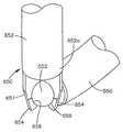
도 4A에 도시된 바와 같이, 대안적인 실시예에 있어서, 삽입 가이드 300은 보어 304, 근위단 306, 원위단 308, 근위의 개구 300a, 원위의 개구 300b, 제1 세로 슬롯 310 및 제2 세로 슬롯 312를 가진 본체부 302를 구비할 수 있다. 보어 304는 스크류 100의 헤드부 104를 수납하도록 구성될 수 있고, 도 3A의 보어 205의 치수 D와 유사한 내부의 치수를 가질 수 있다. 삽입 가이드 300은 예를 들어, 약 50mm 내지 약 300mm 사이, 보다 바람직하게, 약 80mm 내지 약 250mm 사이, 가장 바람직하게, 약 100mm 내지 약 200mm 사이의 길이 L2, 및 예를 들어, 약 5mm 내지 약 25mm 사이, 보다 바람직하게, 약 10mm 내지 약 20mm 사이, 가장 바람직하게, 약 12mm 내지 약 18mm 사이의 외부의 치수 OD2를 가질 수 있다.As shown in FIG. 4A, in an alternative embodiment, the
제1 및 제2 세로 슬롯 310,312는 원위단 308로부터 근위단 306 쪽으로 뻗을 수 있다. 제1 및 제2 세로 슬롯 310,312는 그곳을 통해 고정 봉을 수납하도록 구성될 수 있다. 예를 들어, 제1 및 제2 세로 슬롯들 310,312는 약 3mm 내지 약 7mm 사이, 보다 바람직하게, 약 5mm 내지 약 6.5mm 사이, 가장 바람직하게, 약 5.5mm 내지 약 6mm 사이의 폭 W2를 가질 수 있다. 또한, 제1 및 제2 세로 슬롯들 310,312는 예를 들어, 약 10mm 내지 약 100mm 사이, 보다 바람직하게, 약 20mm 내지 약 80mm 사이, 가장 바람직하게, 약 30mm 내지 약 60mm 사이의 높이 H2를 가질 수 있다. 제1 및 제2 세로 슬롯들 310,312는 동일하거나 다른 폭들 W2 및/또는 높이 H2를 가질 수 있음을 유의해야 한다.The first and second
또한, 삽입 가이드 300은 세로 슬롯들 310,312 사이에 위치될 수 있는 적어도 하나의 추가적 슬롯 314,316을 가질 수 있다. 슬롯들 314,316은 복수의 유연한 갈퀴들 또는 핑거들 318을 형성하기 위해 구성될 수 있다. 수술자가 삽입 가이드 300을 스크류 100의 헤드부 104에 결합(또는 그로부터 삽입 가이드 300을 분리)하는 것을 가능하도록(예, 그래서 가이드 300이 헤드부 104에 클립 결합되거나 그로부터 제거될 수 있도록) 핑거들 318은 굴곡될 수 있다. 슬롯들 314,316은 예를 들어, 약 0.5mm 내지 약 6mm 사이, 보다 바람직하게, 약 1mm 내지 약 5mm 사이, 가장 바람직하게, 약 2mm 내지 약 4mm 사이의 폭 W3을 가질 수 있다. 또한, 슬롯들 314,316은 예를 들어, 약 10mm 내지 약 100mm 사이, 보다 바람직하게, 약 20mm 내지 약 80mm 사이, 가장 바람직하게, 약 30mm 내지 약 60mm 사이의 높이 H3을 가질 수 있다. 슬롯들 314,316은 동일하거나 다른 폭들 W3 및/또는 높이 H3을 가질 수 있음을 유의해야 한다.In addition, the
스크류 100에 삽입 가이드 300을 유지하기 위하여, 삽입 가이드 300의 원위단 308(예, 갈퀴들 318)은 보어 304 속으로 화장할 수 있고 스크류 헤드 104의 그루브 114에 수납될 수 있는 플랜지들 320을 가질 수 있다. 그러한 구성은 삽입 가이드 300이 스크류 100의 헤드부 104로부터 분리되는 것을 방지할 수 있다. 또한, 플랜지들 320은 보어 304 속으로 연장될 수 있는 하나 또는 그 이상의 갈퀴들 322a,322b를 각각 가질 수 있다. 갈퀴들 322a,322b는 세로 슬롯들 310,312 속으로 확장할 수 있는 부분 323a,323b에 위치될 수 있다. 보류부들 322a는 표면들 104a,104b에 맞대어 위치될 수 있고, 보류부들 322b는 헤드부 104의 반대면에 있는 동일한 표면들에 맞대어 위치될 수 있다. 그러한 구성은 채널 108의 U-형상의 부분들을 제1 및 제2 세로 슬롯들 310,312와 정렬시킬 수 있으므로, 고정 봉은 제1 및 제2 세로 슬롯들 310,312를 따라 스크류 100의 채널 108 속으로 움직일 수 있다. 추가적으로, 그러한 구성은 삽입 가이드 300이 헤드부 104에 대해 회전하는 것을 방지할 수 있고, 수술자가 외과 시술 동안 스크류 100의 헤드부 104를 삽입 가이드 300에 대해 움직이는 것을 허용할 수 있는 한편 슬롯들 212,220 및 채널 108은 정렬된채 유지될 수 있다.In order to retain the
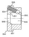
도 4A는 삽입 가이드 350의 대안적인 실시예를 설명한다. 삽입 가이드 350은 내부 슬리브 351과 외부 슬리브 352를 가질 수 있다. 내부 슬리브 351은 원위단 353, 근위단 354, 및 원위단 353으로부터 근위단 354로 통과하는 보어 356을 가질 수 있다. 보어 356은 스크류 100의 헤드부 104를 수납하도록 구성될 수 있고, 예를 들어, 약 8mm 내지 약 20mm 사이, 보다 바람직하게, 약 9mm 내지 약 16mm 사이, 가장 바람직하게, 약 10mm 내지 약 14mm 사이의 내부 치수 ID4를 가질 수 있다. 내부 슬리브 351은 예를 들어, 약 50mm 내지 약 300mm 사이, 보다 바람직하게 약 80mm 내지 약 250mm 사이, 가장 바람직하게, 약 100mm 내지 약 200mm 사이의 길이 L5, 및 예를 들어, 약 5mm 내지 약 25mm 사이, 보다 바람직하게, 약 10mm 내지 약 20mm 사이, 가장 바람직하게, 약 12mm 내지 약 18mm 사이의 외부 치수 OD8을 가질 수 있다.4A illustrates an alternative embodiment of the
내부 슬리브 351은 본체부 355, 및 본체부 355로부터 확장하는 제1 및 제2 아암들 363,364를 가질 수 있다. 아암들 363,364가 서로에 대해 굴곡 가능할 수 있도록, 아암들 363,364는 그들 사이의 제1 세로 슬롯 366 및 제2 세로 슬롯 368을 가질 수 있다. 제1 및 제2 세로 슬롯들 366,368은 원위단 353으로부터 근위단 354 쪽으로 확장할 수 있다. 제1 및 제2 세로 슬롯들 366,368은 그곳을 통해 고정 봉을 수납하도록 구성될 수 있다. 예를 들어, 제1 및 제2 세로 슬롯들 366,368은 약 3mm 내지 약 7mm의 폭과 약 10mm 내지 약 100mm 사이의 높이를 가질 수 있다. 슬롯들 266,268은 바람직하게 후술되는 바와 같이, 그곳을 통해 삽입될 고정 봉을 위한 채널을 형성하기 위해 설명된 바와 같이 정반대로 대향된다. 제1 및 제2 세로 슬롯들 366,368은 다른 높이들 및 폭들을 가질 수 있다. 일체형 또는 분리 가능한 핸들 369는 내부 슬리브 351(예, 근위단 354 부근에)에 부착될 수 있고 외과 시술 동안 삽입 가이드 350을 조작하기 위해 외과의사에 의해 사용될 수 있다. 또한, 내부 슬리브 351은 내부 슬리브의 일부분 358을 따라 확장할 수 있는 작동 메커니즘(예, 나사산 370, 라체트 메커니즘)을 가질 수 있다. 예를 들어, 나사산 370을 가진 실시예에 있어서, 나사산 370은 근위단 354로부터 원위단 353 쪽으로 본체 355를 따라 뻗을 수 있다.The
외부 슬리브 352는 내부 슬리브 351 위에 위치될 수 있으며, 내부 슬리브 351 위에 고정되는 사이즈일 수 있는 내부 치수 ID5를 가질 수 있다. 외부 슬리브 는 예를 들어 약 30mm 내지 약 200mm 사이, 보다 바람직하게, 약 50mm 내지 약 160mm 사이, 가장 바람직하게, 약 75mm 내지 약 125mm 사이의 길이 L6, 및 예를 들어, 약 6mm 내지 약 30mm 사이, 보다 바람직하게, 약 10mm 내지 약 25mm 사이, 가장 바람직하게, 약 12mm 내지 약 20mm 사이의 외부 치수 OD9를 가질 수 있다. 외부 슬리브 352는 내부 슬리브 351의 나사산 370과 결합할 수 있는 결합 부재(예, 내부 나사산 372)를 가질 수 있다. 예를 들어, 외부 슬리브 352를 내부 슬리브 351(예, 회전축 350a)에 대해 회전시킴으로써, 수술자는 외부 슬리브 352를 내부 슬리브 351을 따라 움직일 수 있다. 노브(knob) 374a는 회전을 용이하게 하기 위해 외부 슬리브 352의 외과의사의 파지를 향상시키도록 제공될 수 있다. 외부 슬리브 352는, 외부 슬리브 352의 근위단 374가 내부 슬리브 351의 근위단 354(즉, 근위단 374는 근위단 354로부터 제1 간격일 수 있음) 부근에 위치될 수 있는 제1 위치(도 4C), 및 외부 슬리브 352의 근위단 374가 내부 슬리브의 근위단 354로부터 더 멀어지게 움직일 수 있는 제2 위치(도 4C)(즉, 근위단 374는 근위단 354로부터 제2 간격일 수 있고 제2 간격은 제1 간격보다 클 수 있다)를 내부 슬리브 351 위에 가질 수 있다.The
외부 슬리브 352가 제1 위치에 있을 때, 스크류 100의 헤드부 104는 아암들 362,364 사이에 삽입될 수 있다. 삽입 가이드 350을 스크류 100에 유지시키기 위해, 아암들 362,364의 원위단들 362a,362b 각각은 보어 356 속으로 확장할 수 있고 스크류 헤드 104의 그루브 114에 수납될 수 있는 플랜지들 376을 가질 수 있다. 하나의 아암 만이 플랜지 376을 가질 수 있음을 주의해야 한다. 플랜지(들) 376은 삽 입 가이드 350이 스크류 100의 헤드부 104로부터 분리되는 것을 방지할 수 있다. 몇몇 실시예들에 있어서, 플랜지 376은 아암들 362,364의 원위단들 362a,364a 각각을 따라 확장할 수 있고, 또는, 아암들 362,364의 일부에만 위치될 수 있다. 또한, 각각의 플랜지 376은 세로 슬롯들 366 및/또는 368 속으로 확장할 수 있고 채널 108 부근에서 헤드부 104의 보류부 180에 위치될 수 있는 하나 또는 그 이상의 확장부들 378을 가질 수 있다. 그러한 구성은 삽입 가이드 350이 스크류 100의 헤드부 104에 대해 회전하는 것을 방지한다. 삽입 가이드 350이 스크류 100에 대해 회전하는 것을 방지할 수 있는 그 어떤 구성도 사용될 수 있음을 당업자들은 이해할 것이다. 내부 슬리브 351이 스크류 100에 위치되면, 외부 슬리브 352는 제1 위치(도 4C)로부터 제2 위치(도 4D)로 이동될 수 있으므로, 헤드부 104 주위에 아암들 362,364를 단단하게 결합할 수 있다. 외부 슬리브들 352는 인체 속으로 외부 슬리브 352 및/또는 삽입 가이드 350의 도입을 용이하게 하는 테이퍼 끝단 377a를 가질 수 있다.When the
도 4H 내지 도 4L는 대안적 실시예들 및 삽입 가이드 350'의 부품들을 도시한다. 삽입 가이드는 내부 슬리브 351' 및 외부 슬리브 352'를 가질 수 있다. 내부 슬리브 351'는 내부 슬리브 351과 유사하며 원위단 353', 근위단 354' 및 원위단 353'으로부터 근위단 354'까지 통과하는 보어 356'을 가진다. 보어 356'는 스크류 100의 헤드부 104를 수납하도록 구성된다. 내부 슬리브 351'는 내부 슬리브 351을 위해 전술된 대표적 치수들을 가질 수 있다.4H-4L show alternative embodiments and parts of insertion guide 350 '. The insertion guide may have an inner sleeve 351 'and an outer sleeve 352'. The inner sleeve 351 'is similar to the
도 4J에 도시된 내부 슬리브는 본체부 355', 및 본체부 355'로부터 확장하는 제1 및 제2 아암 362',364'를 가질 수 있다. 아암들이 서로에 대해 굴곡될 수 있도록 제1 세로 슬롯 366' 및 아암들 362',364' 사이로 확장하는 제2 세로 슬롯 368'이 있을 수 있다. 제1 및 제2 세로 슬롯들 366',368'은 원위단 353'으로부터 근위단 354' 쪽으로 확장할 수 있다. 제1 및 제2 세로 슬롯들 366',368'은 그곳을 통해 고정 봉을 수납하도록 구성될 수 있다. 예를 들어, 제1 및 제2 슬롯들 366',368'은 약 3mm 내지 약 7mm의 폭 및 약 10mm 내지 약 100mm 사이의 높이를 가질 수 있다. 슬롯들 366',368'은 바람직하게 후술하게 되는 바와 같이 그곳을 통해 삽입될 고정 봉을 위한 채널을 형성하기 위해 전술한 바와 같이 정반대로 마주보는 것이 바람직하다. 제1 및 제2 세로 슬롯들 366',368'은 다른 높이들과 폭들을 가질 수 있다. 일체형 또는 분리 가능한 핸들(미도시)은 내부 슬리브 351'(예, 근위단 354' 부근)에 부착될 수 있으며, 시술 동안 삽입 가이드 350'을 조작하기 위해 사용자에 의해 사용될 수 있다. 내부 슬리브의 원위단 353', 및 특히 아암들 362',364'는 리세스들, 그루브들 및/또는 스크류 헤드 위의 돌기들 또는 그것이 부착하는 후크와 합치되게 구성될 수 있다.The inner sleeve shown in FIG. 4J may have a body portion 355 'and first and second arms 362', 364 'extending from the body portion 355'. There may be a second longitudinal slot 368 'extending between the first longitudinal slot 366' and the arms 362 ', 364' such that the arms can be bent relative to one another. The first and second vertical slots 366 ', 368' may extend from the distal end 353 'toward the proximal end 354'. The first and second vertical slots 366 ', 368' can be configured to receive the fixing rod therethrough. For example, the first and
내부 슬리브는 칼라(clooar) 352'가 내부 슬리브 351'에 대해 움직이는 것을 허용하는 작동 메커니즘의 부분을 가질 수 있다. 예를 들어, 헬리컬 그루브 371'은 근위단 354' 또는 그 근처로부터 원위단 353' 쪽으로 내부 슬리브의 일 부분을 따라 확장할 수 있다. 칼라 352'는 바람직하게 내부 슬리브 351'의 원위단 353' 위로 고정되고 미끄러지는 크기일 수 있는 내부 치수 ID5를 가질 수 있는 통로 379'를 가질 수 있다. 칼라 352'는 예를 들어, 약 20mm 내지 약 100mm 사이, 보다 바람직 하게, 약 25mm 내지 약 50mm 사이, 가장 바람직하게, 약 30mm의 길이 L6, 및 예를 들어 약 27mm의 외부 치수 OD9를 가질 수 있다.The inner sleeve can have a portion of the actuation mechanism that allows the collar 352 'to move relative to the inner sleeve 351'. For example, the helical groove 371 'may extend along a portion of the inner sleeve from or near the proximal end 354' toward the distal end 353 '. The collar 352 'can preferably have a passage 379' that can have an internal dimension ID5 that can be sized and slipped over the distal end 353 'of the inner sleeve 351'. The collar 352 'can have, for example, a length L6 of between about 20 mm and about 100 mm, more preferably between about 25 mm and about 50 mm, most preferably about 30 mm, and an external dimension OD9 of about 27 mm, for example. .
칼라 352'는 내부 슬리브 351'의 헬리컬 그루브 371'과 결합할 수 있는 결합 메커니즘 372'의 부분을 형성할 수 있다. 칼라 352'의 결합 메커니즘은 볼(ball) 373' 및 칼라 352'의 정 위치에 볼 373'을 유지하는 가동 버튼 374'를 구비할 수 있다. 보어 376'은 칼라 352'에 형성된 통로 378'과 연통 및 이를 교차할 수 있다. 보어 376'의 직경이 볼 373'의 직경보다 작은 경우에 보어 376'이 통로 378'과 만나는 곳의 개구 381'를 제외하고, 보어 376'의 직경은 대체로 볼 373'의 직경보다 크다.The collar 352 'can form part of the coupling mechanism 372' that can engage the helical groove 371 'of the inner sleeve 351'. The engagement mechanism of the collar 352 'may include a move button 374' that holds the ball 373 'in place with the ball 373' and the collar 352 '. Bore 376 'may be in communication with and intersect passage 378' formed in collar 352 '. The diameter of the bore 376 'is generally larger than the diameter of the ball 373', except for the opening 381 'where the bore 376' meets the passage 378 'when the diameter of the bore 376' is smaller than the diameter of the ball 373 '.
볼 373'는 보어 376' 안에 위치되고 그것이 통로 378' 속으로 돌출하도록 움직이며, 스프링 385'은 칼라에 형성된 채널 390' 아래에 위치되고, 가동 버튼 374'는 채널 390' 아래로 삽입된다. 부싱 395'는 채널 390'에 프레스-고정, 나사 결합 또는 다르게 고정되어 가동 버튼 374'를 칼라에 유지하고 버튼 374'는 볼 373'을 칼라 372'에 유지한다. 스프링 385'는 버튼에 있는 공동 393'에 유지되고, 숄더 394'가 부싱 395'에 대해 기댈 수 있도록 스프링 385'는 버튼 374'를 바이어스 시킨다. 버튼 374'는 그루브 또는 리세스 396'을 가지며 버튼 374'는 스프링의 바이어 또는 힘에 대항하여 채널 390' 안에서 움직일 수 있으므로, 그루브 396'는 볼 373'과 정렬될 수 있다. 그루브 396'이 인접한 볼 373'과 정렬되면, 볼이 통로 379' 속으로 덜 돌출하도록 볼은 보어 376' 속으로 밀려들어 갈 수 있다. 버튼 374'가 약화되지 않고 그루브 396' 주위의 버튼의 확대 직경 부 392'가 볼 373'과 접촉할 때, 볼은 통로 379' 속으로 더 많이 확장한다. 가동 버튼 374'는 파이거나 확대된 부분들의 다수의 영역들을 포함할 수 있으므로, 볼 373'는 돌출부들의 필요한 숫자에 의거하여 다른 양으로 통로 379' 속으로 돌출할 수 있다.The ball 373 'is located in the bore 376' and moves so that it protrudes into the passage 378 ', the spring 385' is positioned below the channel 390 'formed in the collar, and the actuation button 374' is inserted below the channel 390 '. Bushing 395 'is press-locked, screwed or otherwise secured to channel 390' to retain actuation button 374 'at the collar and button 374' to hold ball 373 'at collar 372'. The spring 385 'is held in the cavity 393' on the button and the spring 385 'biases the button 374' so that the shoulder 394 'can lean against the bushing 395'. Since the button 374 'has a groove or recess 396' and the button 374 'can move in the channel 390' against the bias or force of the spring, the groove 396 'can be aligned with the ball 373'. If groove 396 'is aligned with adjacent ball 373', the ball can be pushed into bore 376 'such that the ball protrudes less into passage 379'. When the button 374 'is not weakened and the enlarged diameter portion 392' of the button around the groove 396 'contacts the ball 373', the ball extends further into the passage 379 '. Since the actuation button 374 'may include multiple areas of pi or enlarged portions, the ball 373' may protrude into the passage 379 'in a different amount based on the required number of protrusions.
칼라 352'는, 칼라의 근위단이 내부 슬리브 351'의 근위단 354' 근처에서 위치될 수 있는(즉, 칼라의 근위단이 근위단 354'로부터의 제1 간격), 내부 슬리브 351' 위의 제1 위치(미도시)로부터, 칼라 352'의 근위단이 내부 슬리브 351'의 근위단으로부터 더 멀어지게 움직이는(즉, 슬리브의 근위단은 근위단 354'로부터의 제2 간격일 수 있고 제2 간격은 제1 간격보다 큼), 내부 슬리브 351' 위의 제2 위치(도 4H 및 도 4I)까지 내부 슬리브 351'을 따라 움직일 수 있다. 칼라가 제1 위치에 있을 때, 스크류 100의 헤드부 104는 아암들 363',364' 내부-사이에 삽입될 수 있다. 스크류 100에 삽입 가이드 350'을 유지시키기 위하여, 아암들의 원위단들은 바람직하게, 그루브들, 리세스들, 돌기들, 숄더들 또는 스크류의 다른 특징들에 부착된다. 아암들의 원위단은 그 어떤 필요한 스크류, 후크 또는 다른 파스너 장치에 부착하도록 구성될 수 있다. 내부 슬리브 351'이 스크류에 위치되면, 외부 칼라 352'는 아암들 362',364'를 헤드부에 단단하게 결합하기 위해 제2 위치로 이동될 수 있다. 칼라를 제2 위치로 움직이는 것은 아암들이 분리되는 것을 방지하고 따라서 삽입 가이드가 스크류 또는 후크로부터 분리되는 것을 방지한다. 스크류, 후크 또는 다른 고정 장치를 부착함에 의해, 사용자는 스크류, 후크 또는 다른 고정 장치를 유지 및 조작할 수 있다.The collar 352 'is above the inner sleeve 351' where the proximal end of the collar can be positioned near the proximal end 354 'of the inner sleeve 351' (ie, the proximal end of the collar is the first gap from the proximal end 354 '). From a first position (not shown), the proximal end of the collar 352 'moves further away from the proximal end of the inner sleeve 351' (ie, the proximal end of the sleeve can be a second gap from the proximal end 354 'and the second The gap may move along the inner sleeve 351 'to a second position (FIGS. 4H and 4I) above the inner sleeve 351', greater than the first interval. When the collar is in the first position, the
삽입 가이드 350'에 있어서, 헬리컬 그루브 371'은, 도 4I에 도시된 바와 같 이, 그 끝단 375'가 슬롯들 366',368'의 어느 하나를 바람직하게 만나거나, 끝단 375'가 본체부 355'에서 또는 아암들 363',364'의 어느 하나에서 종료될 수 있고, 도 4H에 도시된 바와 같이, 헬리컬 그루브 371'의 원위단 375'가 슬롯 366',368'에 인접하게 종료되도록 구성될 수 있다. 칼라 355'가 내부 슬리브 351'을 따라 미끄러질 때 볼 373'는 바람직하게 그루브 371' 안에서 이동하고, 미끄러지거나 구른다. 볼이 그루브 371'을 따라 이동할 때, 그루브의 헬리컬 경로 때문에, 칼라가 내부 슬리브의 축방향으로 이동할 때 칼라는 회전할 것이다. 헬리컬 그루브의 각도 또는 피치는 칼라의 회전의 양 및 그것이 회전 당 주행하는 거리를 결정할 것이다. 바람직하게, 칼라는 내부 슬리브를 따라 축방향으로 대략 15-20mm 움직인다. 바람직하게 헬리컬 그루브는 그 근위단으로부터 그 원위단 375'까지 360도 각도보다 적게 꼬인다.In the insertion guide 350 ', the helical groove 371' is preferably the end 375 'meets any one of the slots 366', 368 ', as shown in Figure 4I, or the end 375' is the
일 실시예에 있어서, 볼 373'이 세로 슬롯 366',368'에서 이동하도록, 삽입 가이드 350'는 내부 슬리브 351'의 원위단 353'을 외부 칼라 352'의 통로 379'를 통해 미끄러지게 함으로써 조립 및 준비될 수 있다. 볼이 세로 슬롯 366',368'의 끝단에 기댈 때, 버튼 그루브 396'이 볼 373'과 정렬되어서 볼 373'이 내부 슬리브 351' 위의 축방향으로 이동하기 충분한 간극이 볼 373'과 내부 슬리브 351' 사이에 있도록 사용자는 버튼 374'를 약화시킨다. 볼 373'이 내부 슬리브 351'를 넘어선 후, 사용자는 버튼 374'을 떼어 놓을 수 있고 칼라는 내부 슬리브의 원위단 354'으로 움직일 수 있다. 볼 373'이 그루브 371'과 정렬할 때, 볼은 버튼 374'를 위로 밀고 버튼의 만곡면(ramp surface) 397'을 볼 373'에 대하여 미는 스프링 385'의 바이어스로부터 그루브 371' 속으로 움직인다. 볼 373'가 그루브 371' 안에 있으면, 칼라가 근위단 354' 쪽으로 움직일 때 칼라는 회전할 것이다. 스크류 또는 후크를 부착하기 위해, 아암들은 스크류에 부착되고 칼라는 원위적으로(distally) 움직인다. 칼라 352'가 원위적으로 움직일 때, 볼 373'은 헬리컬 그루브 371' 안에서 움직이고 그것이 이동할 때 회전한다. 볼 373'이 그루브 371'의 끝단 375'에 도달할 때, 버튼 374'가 상방 위치로 그리고 볼 373' 위에서 버튼 374'의 확대부 392'로 바이어스 된 상태에서, 버튼 374'가 가압되지 않으면 칼라는 내부 슬리브의 원위단 353' 쪽으로 하방으로 더 이동하지 않을 것이다. 칼라가 원위적 위치에 있는 상태에서, 아암들은 바람직하게 스크류 또는 후크가 삽입 가이드 350'로부터 분리되는 것을 허용하지 않도록 충분히 펼쳐지지 않을 것이다. 이러한 방식에 있어서, 헬리컬 그루브 371의 끝단 375'는 칼라가 내부 슬리브 351' 아래로 원위단 353' 쪽으로 너무 많이 이동하는 것을 방지하는 멈춤 메커니즘 398'로서 기능한다.In one embodiment, the insertion guide 350 'is assembled by sliding the distal end 353' of the inner sleeve 351 'through the passage 379' of the outer collar 352 'so that the ball 373' moves in the longitudinal slots 366 ', 368'. And can be prepared. When the ball rests on the ends of the longitudinal slots 366 'and 368', the button groove 396 'is aligned with the ball 373' so that there is enough clearance for the ball 373 'to move axially above the inner sleeve 351' and the inner sleeve 373 ' The user weakens button 374 'so that it is between 351'. After the ball 373 'has crossed the inner sleeve 351', the user can release the button 374 'and the collar can move to the distal end 354' of the inner sleeve. When the ball 373 'aligns with the groove 371', the ball pushes the button 374 'up and moves into the groove 371' from the bias of the spring 385 'that pushes the ramp surface 397' against the ball 373 '. If the ball 373 'is in the groove 371', the collar will rotate as the collar moves toward the proximal 354 '. To attach the screw or hook, the arms are attached to the screw and the collar moves distally. When the collar 352 'moves distal, the ball 373' moves within the helical groove 371 'and rotates as it moves. When the ball 373 'reaches the end 375' of the groove 371 ', the button 374' is biased to the up position and over the ball 373 'to the enlargement 392' of the button 374 ', if the button 374' is not pressed, the collar Will not move further downward toward the distal end 353 'of the inner sleeve. With the collar in the distal position, the arms will preferably not extend sufficiently to allow the screw or hook to disengage from the insertion guide 350 '. In this manner, the end 375 'of the
버튼 374'의 약화(depressing)는 칼라 352'가 회전 없이 내부 슬리브 351'을 따라 축방향으로 이동하는 것을 허용함으로써 삽입 가이드 350'의 조립을 더 용이하게 할 수 있다. 사용자는 버튼 374'를 가압할 수 있고 그것이 근위단 354'의 끝단 조각 357'에 접촉하거나 그 근처일 수 있도록 칼라를 미끄러지게 할 수 있다. 그 후, 사용자는 볼이 그루브 371'을 찾을 때(즉, 그것이 그루브 위에 위치될 때)까지 버튼을 약화시킴 없이 칼라를 회전시킬 수 있고, 이 경우 스프링 385'는 버튼을 상방으로 바이어스 시킬 것이고 이것은 볼 373'을 외측으로 통로 379' 속으로 그리고 그루브 371' 속으로 밀 것이다.Depressing the button 374 'may further facilitate assembly of the insertion guide 350' by allowing the collar 352 'to move axially along the inner sleeve 351' without rotation. The user can press the button 374 'and slide the collar so that it can be in contact with or near the tip piece 357' of the proximal end 354 '. The user can then rotate the collar without weakening the button until the ball finds groove 371 '(i.e. when it is positioned over the groove), in which case the spring 385' will bias the button upwards The ball 373 'will be pushed outward into the passage 379' and into the groove 371 '.
다른 실시예에 있어서, 멈춤 메커니즘 398'는 확대된 리세스 399'를 포함할 수 있다. 예를 들어, 헬리컬 그루브 371'은 확대된 리세스 399'를 포함할 수 있다. 칼라는 도 4J에 도시된 내부 슬리부 351'에 조립된다. 칼라를 조립하기 위해, 칼라는 볼 373'가 본체 355'에 맞닿을 때까지 내부 슬리브 위로 미끄러진다. 그 후, 그루브 396'이 볼과 정렬되어 볼이 헬리컬 그루브 안에서 움직일 수 있고 칼라 352'가 내부 슬리브 351'의 근위단 354'까지 이동할 수 있도록 버튼 374'는 가압된다. 칼라 352'가 내부 슬리브에서 근위적으로(proximally) 위치된 상태에서, 스크류 또는 후크는 근위단 353'에 부착될 수 있는 한편 버튼은 그루브 386'이 볼 373'과 정렬된 약화 상태에 있다. 볼 373'은 헬리컬 그루브 안에서 움직이고 칼라가 원위적으로 움직일 때 회전한다. 볼 373'이 헬리컬 그루브 371' 안에서 움직일 때, 스프링 385'는 버튼 374'를 상방으로 밀기 때문에 만곡면 397'은 볼 373'을 통로 397' 속 외측으로 밀게 된다. 볼 373'이 확대된 리세스 399' 위로 통과할 때, 만곡면 397'은 볼 373'을 리세스 399' 속으로 밀고 버튼 374'는 확대부 392가 볼 373 위에서 볼과 정렬되도록 상방으로 움직인다. 사용자는 볼이 리세스에 수납되는 것을 느끼고/또는 들어서, 칼라가 내부 슬리브 아래로 더 이동하는 것을 멈춘다. 칼라는 바람직하게 버튼 374'가 가압되지 않으면 원위적으로 더 이상 움직이지 않을 것이다. 헬리컬 그루브 371', 볼 373', 가늘고 긴 리세스 398', 그루브 396' 및 확대부 392의 크기는 확대부 393가 볼 373' 위로 확장하거나 볼을 덮을 때 볼 373'이 리세스 399'를 빠져나오기 어려운 그런 것들이다.In other embodiments, the stop mechanism 398 'may include an enlarged recess 399'. For example, the helical groove 371 'may include an enlarged recess 399'. The collar is assembled to the inner sleeve 351 'shown in FIG. 4J. To assemble the collar, the collar slides over the inner sleeve until the ball 373 'abuts against the body 355'. Thereafter, the groove 396 'is aligned with the ball so that the button 374' is pressed so that the ball can move in the helical groove and the collar 352 'can move to the proximal end 354' of the inner sleeve 351 '. With the collar 352 'proximally positioned in the inner sleeve, the screw or hook can be attached to the proximal end 353' while the button is in a weakened state where the groove 386 'is aligned with the ball 373'. The ball 373 'moves in a helical groove and rotates when the collar moves distal. When the ball 373 'moves in the helical groove 371', the curved surface 397 'pushes the ball 373' outward into the passage 397 'because the spring 385' pushes the button 374 'upwards. As the ball 373 'passes over the enlarged recess 399', the curved surface 397 'pushes the ball 373' into the recess 399 'and the button 374' moves upward so that the
또한, 칼라가 내부 슬리브 아래로 더 이상 움직이지 않거나, 볼 373'과 내부 슬리브 사이의 간극이 너무 작게 되어 슬리브가 그루브 아래로 또는 그것을 넘어 더 이상 이동하지 않도록, 헬리컬 그루브 371'은 리세스 399'를 벗어나는 그루브 371' 또는 헬리컬 그루브의 길이를 따른 몇몇 지점이 더 작게(깊이 및/또는 폭) 될 질 수 있는 위치에서 종료될 수 있다. 세척 또는 다른 목적들 즉, 칼라를 내부 슬리브에 조립하는 목적들을 위해 칼라를 제거하기 위해서는, 볼 373'이 그루브 또는 리세스 396'에 정렬되어 볼이 통로 379' 속으로 덜 돌출되거나 통로 379' 속으로 전혀 돌출하지 않도록 사용자는 버튼 374'를 가압할 수 있다. 버튼 374'를 누른 상태에서, 볼(또는 칼라)과 내부 슬리브 사이에는 더 큰 간극이 있으므로 칼라는 내부 슬리브에 조립될 수 있거나 내부 슬리브로부터 제거될 수 있다.In addition, the helical groove 371 'is a recessed 399' such that the collar no longer moves under the inner sleeve, or the gap between the ball 373 'and the inner sleeve is so small that the sleeve no longer moves below or beyond the groove. Some points along the length of the groove 371 'or helical groove that exits can be terminated at a location that can be made smaller (depth and / or width). To remove the collar for cleaning or other purposes, ie for assembling the collar to the inner sleeve, the ball 373 'is aligned with the groove or recess 396' such that the ball protrudes less into the passage 379 'or into the passage 379'. The user can press the button 374 'so as not to protrude at all. With the button 374 'depressed, there is a larger gap between the ball (or collar) and the inner sleeve so that the collar can be assembled to or removed from the inner sleeve.
대안적으로, 또는 거기에 부가하여, 멈춤 메커니즘 398'은 내부 슬리브 위에 있는 확장 탭들을 구비할 수 있다. 확장 탭들은 유연할 수 있다. 예를 들어, 내부 슬리브는 내부 슬리브 351'에 있는 하나 또는 그 이상의 "U-형상" 절단부(cut)를 포함할 수 있고, U-형상 절단부에 의해 구획되는 탭은 외측으로 구부릴 수 있다. 칼라는 그것이 내부 슬리브 위로 움직일 때 위로 미끄러질 수 있고 U-형상 탭을 내측으로 변형시킬 수 있다. 칼라가 탭 위로 통과할 때, 탭은 그 외측 위치로 복귀하도록 움직일 수 있으므로, 칼라가 내부 슬리브 아래로 움직이면 칼라는 탭에 맞대게 될 것이다. 탭들은 칼라가 내부 슬리브로부터 제거되는 것을 허용하도록 약화될 수 있다.Alternatively, or in addition, the stop mechanism 398 'may have expansion tabs over the inner sleeve. Extension tabs can be flexible. For example, the inner sleeve can include one or more "U-shaped" cuts in the inner sleeve 351 ', and the tabs defined by the U-shaped cuts can be bent outwardly. The collar can slide up as it moves over the inner sleeve and deform the U-shaped tab inwards. As the collar passes over the tab, the tab can move to return to its outer position, so that if the collar moves below the inner sleeve, the collar will be against the tab. The tabs may be weakened to allow the collar to be removed from the inner sleeve.
도 4F 및 도 4G에 도시된 바와 같이, 홀더 382는 스크류 100 및 삽입 가이드 350,350'을 연결하기 위해 외과의사에 의해 사용될 수 있다. 홀더 382는 본체 384, 스크류 100을 수납하기 위한 개구 386, 및 홀더 382에 대해 고정된 위치에서 스크류 100을 유지(즉, 스클 100의 헤드부 104가 홀더 382에 대해 회전되는 것을 방지)하기 위한 고정 부재 388을 구비할 수 있다. 일 실시예에 있어서, 고정 부재 388은 봉(rod)일 수 있고 피벗 389에 대해 홀더 382에 회전되게 연결될 수 있다. 홀더 382의 부품들은 예를 들어, 금속, 세라믹, 플라스틱, 고무, 물질의 조합 또는 복합 재료에 의해 제조될 수 있다. 예를 들어, 부품들은 스테인리스 스틸, 티타늄, 합금, 카본 파이버 복합재, 또는 폴리머(예, 폴리비닐 클로라이드(PVC), 폴리에틸렌, 다양한 종류의 폴리에스테르, 폴리카보네이트, 테프론 코팅 금속, 폴리에테르에테르 케톤(PEEK), 또는 초고분자 중량 폴리에일렌(UHMWPE))로부터 제조될 수 있다. 부품들을 만들기 위해 사용되는 물질을 결정할 때, 내살균력/내세척력(예, 오토클레이브의 사용' 병원에서 살균을 위해 사용되는 세척제), 중량, 내구성, 가해지는 힘에 견디는 능력, 응력 (시술에서 사용되는 혈액 또는 물질들로부터의) 저항 및 특히 수술 동안 대체로 사용되는 라텍스 장갑들을 이용한 부품들의 파지력을 포함하는 다양한 인자들이 고려될 수 있다.As shown in FIGS. 4F and 4G,
홀더 382는 개구 386 근처에 위치될 수 있고 내부 슬리브 351의 원위단 353을 수납할 수 있는 카운터보어(counterbore) 390을 가질 수 있다. 삽입 가이드 350,350'가 그 속에 삽입될 때 카운터보어 390 내부에서 회전되는 것을 방지할 수 있도록 카운터보어 390은 비-원형일 수 있다. 또한, 삽입 가이드 350,350'를 삽입하는 동안 홀더 382가 전복(tip over)/낙하(fall over)되는 것을 방지하기 위하여, 홀더 382는 파스너(예, 볼트, 스크류, 벨크로)에 의해 다른 물체(예, 수술대 또는 도구 키트)에 작동 가능하게 부착되게 구성될 수 있다. 몇몇 실시예들에 있어서, 홀더 382의 중량을 감소시킬 수 있도록 홀더 382는 중 금속(heavy metal)으로 제조될 수 있다.
사용 시, 스크류 100은 개구 386 속으로 삽입될 수 있으므로 스크류 100의 헤드부 104는 턱(ledge) 392에 기대어 놓여질 수 있으며 샤프트 102는 구멍 386을 통해 위치될 수 있다. 그 후, 도 4G에 도시된 바와 같이, 보류 부재(retaining member) 388의 단부 394가 헤드부 104의 채널 108 내부에 위치될 수 있음으로써, 홀더 382에 대해 스크류 100을 고정시킬 수 있도록 보류 부재 388은 회전될 수 있다. 삽입 가이드 350,350'은 그 후 헤드부 104에 연결될 수 있다. 특히, 내부 슬리브 351의 아암들 362,364는 헤드부 104 주위에 위치될 수 있으므로, 보류 부재 388은 세로 슬롯들 366,368의 어느 하나 또는 전부를 통해 위치될 수 있다. 그 후, 아암들 362,364가 헤드부 104에 단단하게 결합할 때까지 외부 슬리브 352의 원위단 377이 내부 슬리브 351의 원위단 쪽으로 움직일 수 있도록, 외부 슬리브 352는 회전될 수 있다. 스크류 100과 삽입 가이드 350은 단일 유니트로서 홀더 382로부터 순차적으로 제거되고 인체에 삽입될 수 있다. 이러한 단계는 추가적인 삽입 가이드들 350,350'을 위해 반복될 수 있다. 그러나, 홀더 382는 불필요할 수 있으며 외과의사는 자신의 손/손가락만을 이용하여 스크류 100와 삽입 가이드 350을 부착할 수 있음을 주의해야 한다.In use, the
도 5는 그곳에 부착되어 피부의 제1 절개부 I1 밖으로 확장하는 삽입 가이드(예, 삽입 가이드 200a)와 함께, 제1 척추뼈 V1의 척추경에 위치된 스크류 100을 설명한다. 도 5는 설명적 목적만을 가지며 그 어떤 삽입 가이드(예, 가이드 300,350,350' 등)가 그 어떤 척추체에 있는 스크류 100에 부착될 수 있음을 주의해야 한다. 스크류 100와 삽입 가이드 200,300,350,350'의 삽입 방법은 하나 또는 그 이상의 회수로 반복될 수 있다. 예를 들어, 도 6 및 도 7에 도시된 바와 같이, 스크류 100은 그 속에 부착되어 피부의 제2 및 제3 절개부 I2, I3 밖으로 각각 확장하는 삽입 가이드(예, 삽입 가이드들 200b,200c)와 함께 제2 및 제3 척추뼈 V2,V3에 삽입될 수 있다. 그러한 구성은 3개의 척추뼈 V1,V2 및 V3의 척추 고정을 허용할 수 있다. 도 5 내지 도 7은 3개의 분리된 절개부들 I1,I2 및 I3를 통해 수행되는 시술을 설명하지만, 척추 고정 시술이 하나의 더 큰 절개부를 통해 수행될 수 있도록, 3개의 스크류들 100과 삽입 가이드들은 동일한 절개부, 캐뉼라 및/또는 견인기에 위치될 수 있음을 주의해야 한다.FIG. 5 illustrates a
스크류들 100과 삽입 가이드가 인체에 삽입된 후, 가이드 슬리브 400,416은 적어도 하나의 삽입 가이드를 통해 위치될 수 있다. 예를 들어, 가이드 슬리브 400는 삽입 가이드 200a,200b 또는 200c를 통해 삽입될 수 있다. 대체적으로, 가이드 슬리브 400,416은 어느 하나의 끝단 삽입 가이드들 200a 또는 200c를 통해 삽입될 것이다. 가이드 슬리브 400,416은 삽입 가이드 200,300,350,350'의 보어 205,304,356의 내부에 고정되게 구성될 수 있다. 슬리브 400은 예를 들어, 약 5mm 내지 약 22mm 사이, 보다 바람직하게, 약 20mm 내지 약 18mm 사이, 가장 바람직하게, 약 12mm 내지 약 16mm 사이의 외부 치수 OD3, 및 예를 들어, 약 4mm 내지 약 21mm 사이, 보다 바람직하게, 약 9mm 내지 약 17mm 사이, 가장 바람직하게, 약 9mm 내지 약 17mm 사이의 내부 치수 ID3를 가질 수 있다. 슬리브 400은 예를 들어, 약 50mm 내지 약 350mm 사이, 보다 바람직하게, 약 80mm 내지 약 270mm 사이, 가장 바람직하게, 약 100mm 내지 약 210mm 사이의 길이 L3를 가질 수 있다. 대안적으로, 가이드 슬리브 400,416은 삽입 가이드 200a,200b 또는 200c의 외측 위에 고정되게 구성될 수 있다. 예를 들어, 가이드 슬리브 400,416은 삽입 가이드 200,300,350,350'이 인체에 삽입되기 전에 삽입 가이드의 원위단 208,216 위(또는 삽입 가이드 300의 원위단 308의 위 또는 내부 슬리브 351의 원위단 353의 위 또는 내부 슬리브 351'의 원위단 353'의 위)에 위치될 수 있다. 그 후, 삽입 가이드 200,300,350,350' 및 슬리브 400,416은 단일의 유니트로서 인체에 삽입될 수 있다. 슬리브 400,416은 삽입 가이드 200,300,350,350'에 대해 회전할 수 있고, 그러한 이유들은 아래에서 명백해 질 것이다. 다른 실시예에 있어서, 슬리브 400,416은 삽입 가이드 200,300,350,350'의 외측 위에 삽입될 수 있고 서로 연결될 수 있는 2개의 조각들로 제조될 수 있다. 대안적으로, 슬리브 400,416이 삽입 가이드 200,300,350,350' 주위에 고정되게 개방될 수 있고 그 주위에서 폐쇄될 수 있도록 슬리브 400,416은 힌지에 의해 연결된 2개의 조각들로 제조될 수 있다. 몇몇 실시들에 있어서, 삽입 가이드가 인체에 삽입되기 전 또는 삽입된 후, 슬리브 400,416은 삽입 가이드의 근위단(인체의 외측에 위치된 삽입 가이드의 부분) 위에 삽입될 수 있음을 당업자들을 이해할 것이다. 예를 들어, 슬리브 400,416은 삽입 가이드 300의 근위단 306 위에 삽입될 수 있다.After the
도 8A 및 도 8B에 도시된 바와 같이, 가이드 슬리브 400은 세로 축 401, 근 위단 404, 근위 개구 400a, 원위단 406, 원위 개구 400b 및 근위단 404로부터 원위단 406으로 뻗어 있는 보어 407을 가질 수 있는 본체 402를 포함할 수 있다. 슬리브 400의 길이 L3은 슬리브 400의 근위단 404가 삽입 가이드 200,300,350,350'의 근위단 214,306,354로부터 각각 돌출할 수 있도록 충분히 길 수 있다. 그러한 구성은 아래에서 더 자세히 설명되는 바와 같이, 외과의사가 시술 동안 슬리브 400를 조작하는 것을 허용할 수 있다. 또한, 가이드 슬리브 400의 근위단 406은 스크류 100의 헤드부 104의 상응하는 홈이 형성된 가장자리(chamfered edge) 104c와 결합할 수 있는 홈이 형성된 내부 가장자리 406c를 가질 수 있다. 홈이 형성된 가장자리 104c 및 406c는 서로 인접되게 위치될 수 있다.As shown in FIGS. 8A and 8B, the
본체 402는 제1 개구 408, 제2 개구 410, 제1 개구 408을 교차하는 제1 세로 개구 412 및 제2 개구 410을 교차하는 제2 세로 개구 414를 가질 수 있다. 예를 들어, 제1 및 제2 개두들 408,410은 제1 및 제2 세로 개구 412,414에 대해 각각 비스듬(예, 수직)할 수 있다. 제1 및 제2 개구들 408,410은 바람직하게 대체적으로 원통형 슬리브 본체 402의 측벽 400s에 형성되고 슬리브 본체 402의 세로 축 401에 바람직하게 수직되게 가늘고 길게 연장된다. 제1 및 제2 세로 개구 412,414는 바람직하게 슬리브 본체 402의 측벽 400s에 형성되고 슬리브 본체 402의 세로 축 401의 방향으로 확장한다. 제1 세로 개구 412 및 제2 세로 개구 414는 원위단 406으로부터 근위단 404 쪽으로 확장할 수 있다. 바람직하게, 제1 개구 408은 슬리브 본체 402의 측벽 400s에 대체로 L-모양의 개구를 형성하기 위해 제1 세로 개구 412에 대체로 수직이다. 바람직하게, 제2 개구 410은 슬리브 본체 402의 측벽 400s에 대체 로 L-모양의 개구를 형성하기 위해 제2 세로 개구 414에 대체로 수직이다. 바람직하게, 제1 세로 개구 412는 제2 세로 개구 414에 대향(약 180도 각도로 형성)된다. 제1 및 제2 개구들 408,410은 제1 및 제2 세로 개구들 412,414에 각각 대체로 수직된 것으로 도시 및 설명되었지만, 제1 및 제2 개구들 408,410은 제1 및 제2 세로 개구들 412,414에 대해 각각 약 0도 내지 약 180도 각도로 형성될 수 있으며, 대체로 L-모양의 개구와 다른 모양들을 형성할 수 있다. 제1 및 제2 개구들 408,410 및 제1 및 제2 세로 개구들 412,414는 고정 봉을 수납하도록 구성될 수 있으며, 보다 바람직하게, 제1 및 제2 개구들 408,410의 폭, 뿐만 아니라 제1 및 제2 세로 개구들 412,414의 폭은 척추 봉의 직경 보다 약간 클수 있으므로 척추 봉은 각각의 개구들을 관통할 수 있다.The
제1 세로 개구 412는 예를 들어, 약 10mm 내지 약 100mm 사이, 보다 바람직하게, 약 20mm 내지 약 80mm 사이, 가장 바람직하게, 약 30mm 내지 약 60mm 사이의 높이 H3을 가질 수 있다. 제2 세로 개구 414는 예를 들어, 약 8mm 내지 약 100mm 사이, 보다 바람직하게, 약 15mm 내지 약 70mm 사이, 가장 바람직하게, 약 20mm 내지 약 60mm 사이의 높이 H4를 가질 수 있다. 제1 및 제2 세로 개구들 412,414는 예를 들어, 약 3mm 내지 약 7mm 사이, 보다 바람직하게, 약 5mm 내지 약 6.5mm 사이, 가장 바람직하게, 약 5.5mm 내지 약 6mm 사이의 폭 W3을 가질 수 있다. 제1 및 제2 세로 개구들 412,414는 동일하거나 다른 폭 W3을 가질 수 있다. 또한, 제1 및 제2 개구들 408,410은 예를 들어, 약 5mm 내지 약 30mm 사이, 보다 바람직하게, 약 6mm 내지 약 20mm 사이, 가장 바람직하게 약 8mm 내지 약 14mm 사이의 폭 W4를 가질 수 있다. 제1 및 제2 개구들 408,410은 동일하거나 다른 폭 W4를 가질 수 있다. 제1 및 제2 세로 개구들 412,414의 폭 W3은 제1 및 제2 개구들 408,410의 폭 W4와 같거나 다를 수 이TEk.The first
가이드 슬리브 400은 예를 들어, 금속, 세라믹, 플라스틱, 고무, 화합물질 또는 복합재로 제조될 수 있다. 예를 들어, 슬리브 400은 스테인리스 스틸, 티타늄, 알루미늄, 합금, 카본 섬유 복합재, 또는 폴리머(예, 폴리비닐 클로라이드(PVC), 폴리에틸렌, 다양한 종류의 폴레에스테르, 폴리카보네이트, 테프론 코팅 금속, 폴리에테르에테르 케톤(PEEK), 또는 초고분자 중량 폴리에틸렌(UHMWPE))으로 제조될 수 있다. 슬리브 400은 비-광택 또는 윤활 코팅일 수 있고 및/또는 방사선투과성 또는 방사선불투과성일 수 있다. 슬리브 400을 제조하는데 사용될는 물질을 결정할 때, 내살균력/내세척력(예, 오토클레이브의 사용; 병원의 살균을 위해 사용되는 세척제), 중량, 내구성, 외력에 견디는 능력, 응력(예, 시술에 사용되는 혈액 또는 물질들) 저항, 특히 시술 동안 대체로 사용되는 라텍스 장갑들을 이용한 부품들의 파지 능력을 포함하는 다양한 인자들이 고려될 수 있다. 또한, 슬리브 400은 예를 들어, 단조, 압출, 사출 성형, 압축 성형, 주조, 기계 가공, 또는 전사 성형에 의해 제조될 수 있다.
도 8C는 슬리브 416의 대안적인 실시예를 설명한다. 슬리브 416은 측벽 418, 근위단 418a, 원위단 418b, 및 근위단 418a로부터 근위단 418b로 뻗어 있는 보어 419를 구비할 수 있다. 슬리브 416은 슬리브 400과 동일한 치수들을 가질 수 있고 동일한 재질로 제조될 수 있다. 또한, 슬리브 416은 두 개의 척추 슬롯들 420,422 를 가질 수 있다. 슬롯 420은 높이 H3과 비슷할 수 있는 높이 H5를 가질 수 있고, 슬롯 422는 슬롯들 412,414와 유사할 수 있는 폭을 가질 수 있다. 또한, 슬롯들 420,422는 슬롯들 412,414와 동일한 폭을 가질 수 있다. 슬리브 400과 유사하게, 슬리브 416은 삽입 가이드 200a,200b,200c, 바람직하게 끝단 삽입 가이드 200a 또는 200c를 통해 위치될 수 있다. 일 실시예에 있어서, 봉 500,550,570,700은 삽입 가이드 200c 속으로, 슬롯들 420,422의 근위단들 420a,422a를 통해 추가적인 삽입 가이드들 200a,200b 속으로 위치될 수 있다. 그 후, 봉 500,550,570,700이 슬리브 416 아래로 슬리브 416의 원위단 418b 쪽으로 움직일 수 있도록, 슬리브 416은 회전될 수 있다. 슬리브 416이 회전되는 것과 동시에 봉 500,550,570,700은 홀딩 도구 600,650,670,800,900을 사용하여 인체 속으로(즉, 스크류들 100 쪽으로) 아래로 밀려질 수 있다. 그러나, 슬리브 416의 회전은, 그것만으로, 봉 500,550,570,700에 충분한 힘을 제공할 수 있으므로, 봉 500,550,570,700이 스크류들 100 쪽으로 아래로 움직일 때, 봉 500,550,570,700은 조직을 밀고 나아간다.8C describes an alternative embodiment of the
홀딩 도구는 가이드 슬리브 400,416과 삽입 가이드들 200,300,350,350'을 통해 고정 봉 또는 척추 봉을 스크류 100의 헤드부 104 속으로 삽입하는데 사용될 수 있다. 도 9는 척추 봉 500과 홀딩 도구 600의 일 실시예를 설명한다. 봉 500 및/또는 홀딩 도구 600은 예를 들어, 금속, 세라믹, 플라스틱, 고무, 화합물질 또는 복합재로 제조될 수 있다. 예를 들어, 봉 500 및/또는 홀딩 도구 600(또는 그 부품들)은 스테인리스 스틸, 티타늄, 알루미늄, 합금, 카본 섬유 복합재, 또는 폴리머(예, 폴리비닐 클로라이드(PVC), 폴리에틸렌, 다양한 종류의 폴레에스테르, 폴리카 보네이트, 테프론 코팅 금속, 폴리에테르에테르 케톤(PEEK), 또는 초고분자 중량 폴리에틸렌(UHMWPE))으로 제조될 수 있다. 슬리브 400은 비-광택 또는 윤활 코팅일 수 있고 및/또는 방사선투과성 또는 방사선불투과성일 수 있다. 봉 500 및/또는 홀딩 도구 600(또는 그 부품들)을 제조하는데 사용되는 물질을 결정할 때, 내살균력/내세척력(예, 오토클레이브의 사용; 병원의 살균을 위해 사용되는 세척제), 중량, 내구성, 외력에 견디는 능력, 응력(예, 시술에 사용되는 혈액 또는 물질들) 저항, 특히 시술 동안 대체로 사용되는 라텍스 장갑들을 이용한 부품들의 파지 능력을 포함하는 다양한 인자들이 고려될 수 있다. 또한, 봉 500 및/또는 홀딩 도구 600(또는 그 부품들)은 단조, 압출, 사출 성형, 압축 성형, 주조, 기계 가공, 또는 전사 성형을 포함하는 다양한 방법들에 의해 제조될 수 있다. 이러한 동일한 물질들 및 방법들은 예를 들어, 아래에서 더 자세히 설명되는 봉 700과 홀딩 도구들 800,900과 같은 봉 및/또는 홀딩 도구들(또는 그 부품들)을 제조하는데 사용될 수 있다.The holding tool can be used to insert the fixation rod or spinal rod into the
도 10A에 도시된 바와 같이, 봉 500은 굴곡된 가늘고 긴 부재일 수 있으며 고체 조각 재질로 제조될 수 있다. 대안적으로, 봉은 곧은 가늘고 긴 부재일 수 있고 및/또는 속이 비어 있을 수 있다. 봉 500은 근위단 502, 원위단 504, 및 그 어떤 모양(예, 라운드, 타원형, 정사각형, 직사각형 또는 다른 다각형)일 수 있는 단면을 가질 수 있다. 봉 500은 삽입 가이드들 200,300,350, 가이드 슬리브 400,416의 개구들/슬롯들을 통해 스크류 100의 헤드부 104에 있는 채널 108 속으로 삽입되도록 구성될 수 있다. 봉 500은 예를 들어, 약 3mm 내지 약 7mm 사이, 보다 바람직하게, 약 5mm 내지 약 6.5mm 사이, 가장 바람직하게, 약 5.5mm 내지 약 6mm 사이의 외부 치수 OD4를 가질 수 있다. 봉 500의 길이 L4는 예를 들어, 약 30mm 내지 약 200mm 사이, 보다 바람직하게, 약 35mm 내지 약 180mm 사이, 가장 바람직하게, 약 40mm 내지 약 150mm 사이일 수 있으며, 봉 500의 길이 L4는 예를 들어, 그곳을 통해 봉 500이 삽입될 스크류들 100의 숫자 및/또는 스크류들 100 사이의 거리(환자의 골격에 의해 지시될 수 있음)의 하나의 요소일 수 있다. 봉 500이 굴곡된 경우의 실시예에 있어서, 곡률 반경 R1은 예를 들어, 약 50mm 내지 약 500mm 사이, 보다 바람직하게, 약 80mm 내지 약 300mm 사이, 가장 바람직하게, 약 100mm 내지 약 200mm 사이일 수 있다.As shown in FIG. 10A,
봉 500이 인체를 통해 삽입될 때 원위단 504 주위에서 조직을 용이하게 움직이는 것을 도울 수 있도록, 봉 500의 원위단 504는 라운드, 뭉툭함 및/또는 테이퍼 를 형성할 수 있다. 원위단 504는 예를 들어, 약 3mm 내지 약 15mm 사이, 보다 바람직하게, 약 3mm 내지 약 12mm 사이, 가장 바람직하게, 약 5mm 내지 약 10mm 사이의 곡률 반경 R을 가질 수 있다. 도 10A 및 도 10B에 도시된 바와 같이, 근위단 502는 홀딩 도구 600의 적어도 일 부분(예, 부착부 612)에 부착하기 위한 수납부 506을 가질 수 있다. 도 9에 설명된 바와 같이, 일 실시예에 있어서, 수납부 506은 대체로 U-형상의 구성을 형성하는 측벽 512를 가질 수 있다. 수납부 506은 홀딩 도구 600과 결합하도록 구성될 수 있으므로, 봉 500은 축 510을 기준으로 홀딩 도구 600에 대해 약 360도 각도로 회전 및/또는 회동할 수 있고 및/또는 축 510을 기준으로 홀딩 도구 600에 대해 약 100도 각도로 회전 및/또는 회동할 수 있다. 수납부 506의 측벽 512는 측벽 512를 완전히 통하거나 측벽 512 속으로 부분적으로 확장 (예, 리세스 또는 틈)할 수 있는 적어도 하나의 보어 514를 구비할 수 있다. 보어 514는 홀딩 도구 600의 상응하는 부분들(예, 반구 부분들 616)을 수납할 수 있다. 리세스를 가진 실시예에 있어서, 리세스는 반구형 모양일 수 있고, 홀딩 도구 600의 반구 부분 616을 수납할 수 있다.The
도 11A 내지 도 12B에 도시된 바와 같이, 홀딩 도구 600은 외부 부재 602 및 내부 부재 604를 포함할 수 있다. 외부 부재 602는 원위단 606, 근위단 608 및 근위단 606으로부터 근위단 608까지 뻗을 수 있는 통로 610을 가질 수 있다. 외부 부재 602는 봉 500의 외부 치수 OD4와 비슷하거나 동일하게 구성될 수 있는 외부 치수 OD5를 가질 수 있다. 원위단 606은 거의 구형 또는 반구형 모양일 수 있는 부착부 612를 가질 수 있다. 부착부 612는 봉 500의 수납부 506에 삽입되도록 구성될 수 있다. 예를 들어, 부착부 612는 예를 들어, 약 1mm 내지 약 6mm 사이, 보다 바람직하게, 약 1.5mm 내지 약 4mm 사이, 가장 바람직하게, 약 2mm 내지 약 3mm 사이의 곡률 반경 R2를 가질 수 있다.As shown in FIGS. 11A-12B, the holding
슬릿 614는 부착부 612를 관통할 수 있고, 원위단 616으로부터 근위단 608까지 뻗을 수 있다. 슬릿 614는 부착부 612가 두 개의 구형 모양 또는 사분면 부분들(quadrant portions) 616을 가지게 할 수 있다. 그러한 구성은 부착부 612가 봉 500의 수납부 506 속으로 삽입될 수 있고, 특히 반구부들 616이 봉 500의 보어들(리세스들/틈들) 514 속으로 삽입 및/또는 스냅 결합될 수 있도록 부착부 612는 유연해질 수 있다.
홀딩 도구 600의 근위단 608은 수술자가 외부 부재 602를 조작하기 위한 파 지면을 제공할 수 있는 확대부 618을 가질 수 있다. 확대부 618은 수술자를 위해 개선된 파지면을 제공하는 하나 또는 그 이상의 그루브들 620을 가질 수 있다. 일 실시예에 있어서, 확대부 618은 개선된 파지면을 제공하기 위해 결(우툴두툴)이 형성될 수 있다. 통로 610은 근위단 608일 수 있는 결합부 622를 가질 수 있다. 결합부 622는 나사부일 수 있고 내부 부재 604의 상응하는 결합부 624(예를 들어, 나사와 같음)와 결합하기 위해 사용될 수 있다.The
도 12A 및 도 12B에 도시된 바와 같이, 내부 부재 604는 원위단 626, 근위단 628, 원위단과 근위단 628 사이의 결합부 624를 가질 수 있다. 내부 부재 604는 내부 부재 604가 외부 부재 602의 통로 610에 수납될 수 있고, 그 안에서의 회전 및 축방향 미끄러짐에 의해 움직일 수 있도록 구성될 수 있는 외부 치수 OD5를 가질 수 있다. 외부 치수 OD6은 예를 들어, 약 2mm 내지 약 5mm 사이, 보다 바람직하게, 약 2.5mm 내지 약 4.5mm 사이, 가장 바람직하게, 약 3mm 내지 약 4mm 사이일 수 있다.As shown in FIGS. 12A and 12B, the
근위단 626은 내부 부재 604의 외부 치수 OD6과 비교하여 축소된 치수를 가질 수 있다. 이것을 수행하는 하나의 방법은 내부 부재 604의 길이를 따라 경사면(bevel) 630을 제공하여 경사면 630 후의 원위 방향에서 내부 봉 604의 치수를 감소하는 것이다. 팁 632는 원위단에 형성될 수 있고, 라운드 모양, 뭉툭한 모양, 테이퍼 모양, 뾰족한 모양 또는 그 어떤 다른 모양일 수 있다. 예를 들어, 팁 632는 약 0.3mm 내지 약 1.5mm 사이, 보다 바람직하게, 약 0.5mm 내지 약 1.3mm 사이, 가장 바람직하게, 약 0.7 mm 내지 약 1mm 사이의 곡률 반경 R3을 가질 수 있다. 내 부 부재 604의 근위단 628은 수술자가 내부 부재 604, 외부 부재 602, 홀딩 도구 600 및/또는 봉500을 조작하기 위한 파지면을 제공할 수 있는 확대부 634를 가질 수 있다. 확대부 634는 수술자를 위한 개선된 파지면을 제공하는 하나 또는 그 이상의 그루브 636을 가질 수 있다. 일 실시예에 있어서, 확대부 634는 개선된 파지면을 제공하는 결(우툴두툴)이 형성될 수 있다.The
사용시, 외부 부재 604의 부착부 612는 봉 500의 수납부 506에 위치될 수 있다. 내부 부재 604는 외부 부재 602의 통로 614 내부에 위치될 수 있고, 내부 부재 604의 결합부 624가 외부 부재 602의 결합부 622와 결합할 수 있도록 움직인다. 내부 부재 604의 제1 방향(예, 시계 방향) 회전은 내부 부재 604의 원위부 626을 반구부들 616 사이에서 움직일 수 있다. 내부 부재 604가 제1 방향으로 회전하고 내부 부재 604의 원위부 626이 반구부들 616 사이에서 움직일 때, 원위부 626은 반구부 616을 외측으로, 수납부 506의 보어들 514 속으로 밀 수 있다. 그러한 구성은 봉 500과 홀딩 도구 600이 서로 분리되는 것을 방지할 수 있는 한편, 동시에, 봉 500과 홀딩 도구 600이 서로에 대해 회전 및 회동하는 것을 허용할 수 있다. 봉 500과 홀딩 도구 600의 서로에 대한 각 방위(angular orientation)를 고정하기 위하여, 내부 부재 604는 외부 부재에서 더 멀리 나사가 형성될 수 있으므로 내부 부재 604의 팁 632는 외부 부재 602의 가장 원위의 부분 606을 넘어서 확장할 수 있다. 팁 632는 그 후 수납부의 리세스 506a 또는 506b에 삽입될 수 있다. 팁 632가 리세스 506b에 위치될 때, 홀딩 도구 600은 도 9에 도시된 바와 같이 봉 500에 대해 비스듬히 유지될 수 있다. 팁 632가 리세스 506a에 위치될 때, 봉 500의 축 500a는 도 21A에 도시된 바와 같이 홀딩 도구 600의 축 600a와 정렬될 수 있다. 봉 500과 홀딩 도구 600은 내부 부재 604를 제2 방향(예, 반시계 방향) 회전에 의해 서로 분리될 수 있으므로 내부 부재 604의 원위단 626은 외부 부재 602의 원위단 606으로부터 멀어지게 움직일 수 있다. 내부 부재 604의 원위단 626이 부분들 616 사이에서 제거된 상태에서, 외부 부재 602의 부착부 612는 굴곡될 수 있고 봉 500의 수납부 506으로부터 제거될 수 있다.In use, the
도 9A는 대안적인 봉 550과 홀딩 도구 650을 설명한다. 봉 550은 홀딩 도구 650에 의해 결합될 수 있는 결합부 552를 가질 수 있다. 홀딩 도구 650은 내부 슬리브 651과 외부 슬리브 652를 가질 수 있다. 내부 슬리브 651은 결합부 552와 결합할 수 있는 복수(예, 3 개)의 아암들 654를 가질 수 있다. 결합부 552는 보양이 구형일 수 있고, 아암들 654는 결합부 552 주위에 위치될 수 있다. 아암들 654는 결합부 552의 모양과 상응하는 만곡면들 656을 가질 수 있다. 외부 슬리브 652는, 외부 슬리브 652의 원위단 652a가 아암들 654로부터 떨어져 위치될 수 있는 제1 위치, 및 외부 슬리브 652의 원위단 652a가 아암들 654 근처(예, 위)에 위치될 수 있는 제2 위치를 가질 수 있다. 사용 시, 외부 슬리브 652가 제1 위치에 있을 때 아암들 654는 결합부 552에 부착될 수 있다. 아암들 654는 결합부 552에 클립/스냅 결합될 수 있다. 이러한 구성에 있어서, 봉 550은 하나보다 많은 축을 기준으로 홀딩 도구 650에 대해 회동 가능할 수 있다. 홀딩 도구 650에 대한 봉 550의 방위를 고정하기 위하여, 외부 슬리브 652는 제1 위치로부터 제2 위치까지 움직일 수 있다. 외부 슬리브 652의 원위단 652a가 아암들 654 위에 위치된 상태에서, 아암들 654는 결합부 552에 대해 단단하게 유지될 수 있고, 그래서 홀딩 도구 650에 대해 봉 550의 위치를 고정할 수 있다.9A illustrates an
도 9B는 봉 570과 홀딩 도구 670의 다른 실시예를 도시한다. 봉 570은 그 어떤 모양(예, 원형, 다각형)일 수 있는 결합부 572를 가질 수 있고 하나 또는 그 이상의 편평면들 574를 가질 수 있다. 홀딩 도구 670은 내부 슬리브 672와 외부 슬리브 674를 가질 수 있다. 내부 슬리브 672는 봉 570의 결합부 572 주위에 위치되게 구성될 수 있는 한 쌍의 갈퀴들 676을 가질 수 있다. 각각의 갈퀴 676은 결합부 572의 편평면들 574와 결합하기 위한 하나 또는 그 이상의 핀들 678을 가질 수 있다. 핀들 678은 편평면들 574, 결합부 573 및/또는 봉 570보다 다른 물질로 제조될 수 있다. 특히, 핀들 678은 편평면들 574, 결합부 572 및/또는 봉 570보다 더 단단한 재질로 제작될 수 있으며(예, 핀들 678은 스틸로 제작될 수 있고, 편평면들 574, 결합부 572 및/또는 봉 570은 티타늄으로 제조될 수 있다), 그 이유는 아래에서 더 명백해 질 것이다. 외부 슬리브 674는, 외부 슬리브 674의 원위단 674a가 갈퀴들 676으로부터 떨어져 위치될 수 있는 제1 위치, 및 외부 슬리브 674의 원위단 674a가 갈퀴들 676 근처(예, 위)에 위치될 수 있는 제2 위치를 가질 수 있다. 사용 시, 외부 슬리브 652가 제1 위치에 있을 때, 갈퀴들 676은 결합부 572 주위에 위치될 수 있다. 이러한 구성에 있어서, 봉 570은 홀딩 도구 670에 대해 이동(회동) 가능할 수 있다. 홀딩 도구 670에 대한 봉 570의 방위를 고정하기 위하여, 외부 슬리브 674는 제1 위치로부터 제2 위치까지 움직일 수 있다. 외부 슬리브 674의 원위단 674a가 갈퀴들 676 위에 위치된 상태에서, 갈퀴들 676과 핀들 678은 결합부 572의 편평면들 574에 대하여 압축될 수 있다. 특히, 핀들 678이 편평면들 574보다 단단한 재질로 제조될 때, 편평면들 574에 대한 갈퀴들 676의 압축은 핀들 678의 변형, 편평면들 574에 대한 약화/만입 및/또는 파기의 생성을 초래할 수 있고, 그리하여 홀딩 도구 670에 대해 봉 570의 위치를 고정시킨다.9B shows another embodiment of
도 13A 및 도 13B는 봉 700과 홀딩 도구 800의 다른 실시예를 설명한다. 도 14a 및 도 14B에 도시된 바와 같이, 봉 700은 만곡된 가늘고 긴 부재일 수 있고 고체 조각으로 제조될 수 있다. 대안적으로, 봉은 곧고 가늘고 긴 부재일 수 있고 및/또는 속이 비어 있을 수 있다. 봉 700은 근위단 702 및 원위단 704를 가질 수 있고, 예를 들어, 라운드형, 타원형, 정삭각형, 직사각형 또는 다른 다각형과 같이 그 어떤 모양일 수 있다. 봉 700은 삽입 가이드 200,300,350,350', 가이드 슬리브 400을 통해 스크류 100의 헤드부 104에 있는 채널 108 속으로 삽입될 수 있다. 봉 700은 예를 들어, 약 3mm 내지 약 7mm 사이, 보다 바람직하게, 약 5mm 내지 약 6.5mm 사이, 가장 바람직하게, 약 5.5mm 내지 약 6mm 사이의 외부 치수 OD7을 가질 수 있다. 봉 700의 길이 L7은 예를 들어, 약 30mm 내지약 200mm 사이, 보다 바람직하게, 약 35mm 내지 약 180mm 사이, 가장 바람직하게, 약 40mm 내지 약 150mm 사이일 수 있고, 봉 700의 길이 L7은 예를 들어, 봉 700이 삽입될 수 있는 스크류들 100의 숫자 및/또는 스크류들 100 사이의 거리(환자의 골격에 의해 지시될 수 있음)의 인자일 수 있다. 봉 700이 굴곡된 경우의 실시예에 있어서, 곡률 반경 R6은 예를 들어, 약 50mm 내지 약 500mm 사이, 보다 바람직하게, 약 80mm 내지 약 300mm 사이, 가장 바람직하게, 약 100mm 내지 약 200mm 사이일 수 있다.13A and 13B illustrate another embodiment of the
원위단 704는 라운드질 수 있고, 봉 700이 인체를 통해 삽입될 때 원위단 705 주위에서 조직을 움직이는 것을 도울 수 있는 점(point) 및/또는 테이퍼를 가진다. 예를 들어, 원위단 704는 약 2mm 내지 약 15mm 사이, 보다 바람직하게, 약 3mm 내지 약 12mm 사이, 가장 바람직하게, 약 5mm 내지 약 10mm 사이의 곡률 반경 R7을 가질 수 있다. 봉 700의 근위단 702는 봉 700이 홀딩 도구 800의 적어도 일 부분(예, 갈퀴들 828)에 작동 가능하게 부착될 수 있도록 구성될 수 있는 결합부 706을 가질 수 있다. 일 실시예에 있어서, 결합부 706은 원형의 외형을 가질 수 있다. 그러나, 다른 모양들도 또한 사용될 수 있음을 유의해야 한다. 봉 700이 축 710을 기준으로 홀딩 도구 800에 대해 약 100도 각도 회전할 수 있도록 결합부 706은 홀딩 도구 800의 수납부들(예, 리세스들 830, 도 15B)과 결합할 수 있는 하나 또는 그 이상의 돌기들 708을 가질 수 있다. 도 14A 및 도 14B에 도시된 바와 같이, 돌기들 708은 예를 들어, 원형 모양을 가질 수 있고, 상응하는 원형 모양들을 가질 수 있는 리세스들 830과 결합할 수 있다.The
도 15A 및 도 15B에 도시된 바와 같이, 홀딩 도구 800은 외부 슬리브 802, 내부 슬리브 804, 내부 슬리브 804에 위치된 가늘고 긴 부재 806, 및 외부 슬리브 802와 작동 가능하게 연결된 작동 메커니즘 807을 포함할 수 있다. 홀딩 도구 800의 구성은 예를 들어, 부품들의 세척을 포함하는 다수의 이유에 의해 수술자가 부품들을 해체하는 것을 허용할 수 있다.As shown in FIGS. 15A and 15B, the holding
도 16에 도시된 바와 같이, 외부 슬리브 802는 원위단 808, 근위단 810, 및 원위단 808로부터 근위단 810으로 그곳을 관통하여 뻗어 있는 채널 812를 가질 수 있다. 일 실시예에 있어서, 외부 슬리브 802는 원통형 튜브일 수 있고, 홀딩 도구 800를 인체로 삽입하는 것을 도울 수 있도록 원위단 808에 있는 테이퍼 814를 가질 수 있다. 외부 슬리브 802는 예를 들어, 약 3mm 내지 약 10mm 사이, 보다 바람직하게, 약 4mm 내지 약 9mm 사이, 가장 바람직하게, 약 5mm 내지 약 8mm 사이의 외부 치수 OD16 및 예를 들어, 약 30mm 내지 약 100m 사이, 보다 바람직하게, 약 40mm 내지 약 150mm 사이, 가장 바람직하게, 약 50mm 내지 약 100mm 사이의 길이 L16을 가질 수 있다. 외부 슬리브 802의 근위단 810은 확대된 직경부 816을 가질 수 있고, 작동 메커니즘 806 내부에 고정되게 구성될 수 있다. 외부 슬리브 806이 내부 슬리브 804 위로 움직일 수 있도록 채널 812는 내부 슬리브 804를 수납하도록 구성될 수 있다. 채널 812는 내부 슬리브 804의 상응하는 결합부 834와 결합할 수 있는 결합부 818을 가질 수 있다. 결합부 818은 결합부 834 위의 상응하는 나사산과 상호작용하게 될 나사산을 가질 수 있다.As shown in FIG. 16, the
도 17A 내지 도 17C에 도시된 바와 같이, 내부 슬리브 804는 원위단 820, 근위단 822, 및 원위단 820으로부터 근위단 822까지 그곳을 통해 뻗어 있는 채널 824를 가질 수 있다. 내부 슬리브 804는 외부 슬리브 802의 채널 812 내부에 위치되게 구성될 수 있는 외부 치수 OD17을 가질 수 있으므로, 외부 슬리브 802와 내부 슬리브 804는 서로에 대한 회전 및/또는 축방향 미끄러짐 운동을 할 수 있다. 예를 들어, 내부 슬리브 804는 약 2mm 내지 약 9mm 사이, 보다 바람직하게, 약 2.5mm 내지 약 8mm 사이, 가장 바람직하게, 약 3mm 내지 약 7mm 사이의 외부 치수 OD17을 가질 수 있다. 내부 슬리브 804는 예를 들어, 약 40mm 내지 약 250mm 사이, 보다 바람직 하게, 약 60mm 내지 약 200mm 사이, 보다 바람직하게, 약 80mm 내지 약 150mm 사이의 길이 L17을 가질 수 있다. 내부 슬리브 804의 근위단 822는 도구에 의해 결합되게 구성될 수 있다. 예를 들어, 근위단 822는 육각 모양일 수 있고/또는 그루브 822a를 가질 수 있다. 육각 모양과 그루브 822a는 수술자가 홀딩 도구 800과 관련하여 사용할 수 있는 다양한 도구들의 부착을 위한 인터페이스를 제공할 수 있다. 다른 실시예에 있어서, 근위단 822는 홀딩 도구 800의 파지를 위한 향상된 파지력을 제공하는 결(우툴두툴함)이 형성될 수 있고 거기에 부착된 핸들을 가질 수 있다.As shown in FIGS. 17A-C, the
또한, 슬릿 826은 내부 슬리브 804의 원위단 820을 통과할 수 있고, 원위단 820으로부터 근위단 822까지 뻗을 수 있다. 슬릿 826은 원위단 820이 유연할 수 있는 적어도 두 개의 갈퀴들 828을 가지게 할 수 있다. 갈퀴들 828은 리세스들 830을 가질 수 있으므로, 봉 700의 결합부 706이 슬롯 826의 갈퀴들 828 사이에 삽입될 때, 리세스들 830은 결합부 706의 돌기들 708을 수납할 수 있다. 이러한 방식에 있어서, 내부 슬리브 804 및 결과적으로, 홀딩 도구 800은 봉 700에 작동가능하게 연결될 수 있다. 그러한 구성은 봉 700과 홀딩 도구 800이 서로 분리되는 것을 방지하는 한편, 동시에, 축들 710,832를 기준으로 홀딩 도구 800에 대한 봉 700의 회전 또는 회동을 허용할 수 있다. 리세스들 830은 원형의 모양 또는 다른 모양(몇몇 실시예들에 있어서, 돌기들 708의 모양과 상응할 수 있는)일 수 있고, 예를 들어, 약 1mm 내지 약 8mm 사이, 보다 바람직하게, 약 2mm 내지 약 7mm 사이, 가장 바람직하게, 약 3mm 내지 약 5mm 사이의 치수(직경)을 가질 수 있다.
가늘고 긴 부재 806이 채널 824 내부에서 움직일 수 있도록(예, 회전 및/또는 축방향 미끄러짐) 내부 슬리브 804의 채널 824는 가늘고 긴 부재 806을 수납하도록 구성될 수 있다. 가늘고 긴 부재 806은 원위단 834, 근위단 836, 및 원위단 834와 근위단 836 사이에 위치된 적어도 하나의 가이드 부재 838을 가질 수 있다. 가늘고 긴 부재 806은 원통형 모양을 가질 수 있지만, 당업자들은 그것이 내부 슬리브 804의 채널 824 내부에서 움직일 수 있는 한 부재 806은 그 어떤 모양일 수 있음을 이해할 것이다. 가늘고 긴 부재 806(도 18)은 약 1.5mm 내지 약 8mm 사이, 보다 바람직하게, 약 3mm 내지 약 7mm 사이, 가장 바람직하게, 약 2.5mm 내지 약 6mm 사이의 외부 치수 OD18을 가질 수 있다. 가늘고 긴 부재는 예를 들어, 약 50mm 내지 약 300mm 사이, 보다 바람직하게, 약 60mm 내지 약 250mm 사이, 가장 바람직하게, 약 70mm 내지 약 200mm 사이의 길이 L18을 가질 수 있다. 가늘고 긴 부재 806의 원위단 834는 테이퍼질 수 있으므로 원위단 834는 점 840을 가질 수 있다. 또한, 가이드 부재 838은 내부 슬리브 804의 근위단 822로부터 원위단 820까지 뻗을 수 있는, 내부 슬리브 804의 슬롯들 842 내부에서 움직이게 구성될 수 있다. 슬롯 842는 예를 들어, 약 5mm 내지 약 60mm 사이, 보다 바람직하게, 약 10mm 내지 약 50mm 사이, 가장 바람직하게, 약 15mm 내지 약 40mm 사이의 길이 LS를 가질 수 있다. 가이드 부재 838은 가늘고 긴 부재 806이 내부 부재 804의 채널 824 내부에서 축 801을 따라 움직이는 것을 허용하는 한편 내부 슬리브 804(즉, 축 801을 기준으로)에 대한 가늘고 긴 부재 806의 회전 운동을 방지할 수 있다. 도 15B에 도시된 바와 같이, 가이드 부재 838은 외부 슬리브 802의 근위단 810과 작동 메커니즘 807 사이에 위치될 수 있다.The
작동 메커니즘 807은 가늘고 긴 부재 806 및/또는 외부 슬리브 802를 내부 슬리브 804에 대해 움직이는데 사용될 수 있다. 도 19A 내지 도 19E에 도시된 바와 같이, 작동 메커니즘 806은 본체부 844, 본체부 844를 관통하여 외부 슬리브 802의 확장단 816을 수납하게 구성될 수 있는 제1 통로 846, 및 내부 슬리브 804를 수납하도록 구성될 수 있는 제2 통로 848을 가질 수 있다. 그러한 구성은 가이드 부재 838 및/또는 외부 슬리브 802의 근위단 810이 맞대어 배치될 수 있는 숄더 851을 형성할 수 있다. 이러한 방식에 있어서, 외부 슬리브 802와 가늘고 긴 부재 806은 내부 슬리브 804에 대해 축 801을 따라 함께 이동할 수 있다.The
본체부 844는 그곳을 관통하고, 제1 통로 846을 교차하고 보류 부재 852(도 19A 및 도 19B)를 수납하는 구성일 수 있는 보어 850을 가질 수 있다. 제2 보어 854는 보어 850을 교차할 수 있고 보어 850에 대해 경사(약 45도)질 수 있다. 보어 854는 보류 부재 852와 결합할 수 있는 홀딩 부재 856을 수납할 수 있다. 예를 들어, 홀딩 부재 856은 구형의 끝단 858(도 15B)일 수 있고 보어 850 속으로 돌출할 수 있고 보류 부재 852 및 특히, 보류 부재 852의 수납부 860a,860b와 결합할 수 있는 볼 플런저(ball plunger)일 수 있다. 또한, 보어 854는 나사산 856을 가질 수 있고 홀딩 부재 856은 보어 854의 나사산 856과 결합하기 위한 나사산이 형성된 외면(미도시)을 가질 수 있다. 이러한 방식에 있어서, 홀딩 부재 856은 보어 854 내부에 임시적으로 위치될 수 있다. 그러한 구성은 작동 메커니즘 807의 세척을 위해 홀딩 부재 856의 해체/제거를 가능하게 한다. 다른 실시예들에 있어서, 홀딩 부재 856은 보류 부재 852에 결합하기 위해 보어 854 내부에 영구적으로 위치(예, 용접, 접착)될 수 있다.
보류 부재 854는 보어 844의 어느 한 측면에 있는 리세스 862를 통해 부분적으로 보어 850 속으로 위치될 수 있다. 보류 부재 852는 근위단 864, 원위단 866 및 근위단 위의 노브 868을 가질 수 있다. 테이퍼질 수 있는 노브 868은 리세스들 862의 어느 하나의 내부에 위치될 수 있으므로, 수술자는 본체 844에 대해 보류 부재 852를 회전시킬 수 있다. 보류 부재 852의 원위단 866은 그 주위에 위치될 수 있으므로 보류 부재 853은 보어 850에 회전 가능하게 유지될 수 있다. 링 870은 보류 부재 852에 결합될 수 있으므로 링 870은 예를 들어, 작동 메커니즘 807의 세척을 허용하도록 보류 부재 852(예, 링 870과 보류 부재 852 위의 보조 나사산)로부터 제거될 수 있다. 다른 실시예들에 있어서, 링 870은 보류 부재 852에 영구적으로 고정(예, 레이저 용접에 의해)될 수 있다. 노브 332는 보어 850의 치수보다 더 클 수 있는 치수를 가질 수 있으므로 보류 부재 852는 노브 332와 링 870에 의해 보어 850에 유지될 수 있다.
보류 부재 852는 외부 슬리브 802의 근위단 810 및 특히, 확대부 816이 그 안에 위치될 수 있도록 구성될 수 있는 노치 872를 또한 구비할 수 있다. 예를 들어, 노치 872는 외부 슬리브 802의 확대부 816의 모양과 곡률 반경과 거의 동일할 수 있는 모양 및 크기를 가질 수 있다. 보류 부재 852가 외부 슬리브 802의 리세스 816a와 상호 영향을 주기 때문에 보류 부재 852가 보어 850 및 리세스 826a 내부에서 회전될 수 있도록 보류 부재 852는 보어 850에 위치될 수 있다. 보류 부재 852 가 회전되어 노치 872가 리세스 816a와 면할 때, 외부 슬리브 802 및 결과적으로 가늘고 긴 부재 806은 작동 메커니즘 807에 대해 자유롭게 움직일 수 있다(예, 외부 슬리브 802 및/또는 가늘고 긴 부재 806은 축 801을 따라 통로 846 안과 밖으로 움직일 수 있고/또는 외부 슬리브 802는 작동 메커니즘 807에 대해 회전될 수 있다). 이러한 방식에 있어서, 외부 슬리브 802 및 가늘고 긴 부재 806은 작동 메커니즘 807로부터 제거 또는 분리될 수 있다. 보류 부재 852는 수납부 860b와 결합하는 홀딩 부재 856에 의해 이 위치에 유지될 수 있다. 보류 부재 852가 예를 들어, 180도 각도로 회전될 때, 노치 872는 리세스 816a로부터 떨어져 면하고 보류 부재 852의 외면 850a(노치 872와 정반대로 마주하는 면)은 리세스 816a 내부에 위치될 수 있다. 보류 부재 852는 외부 슬리브 802 및/또는 가늘고 긴 부재 806이 축 801을 따라 작동 메커니즘 807에 대해 움직이는 것을 방지할 수 있다. 또한, 외부 슬리브 802는 작동 메커니즘 807에 대해 회전되는 것이 방지될 수 있다. 보류 부재 852는 수납부 860a와 결합하는 홀딩 부재 856(예, 구형 끝단 858)에 의해 이 위치에 유지될 수 있다. 그러한 위치에 있어서, 작동 메커니즘 807은 외부 슬리브 802 및/또는 가늘고 긴 부재 806을 내부 슬리브 804에 대해 축 801을 따 움직이고/또는 축 801에 대해 외부 슬리브 802를 회전시키는데 사용될 수 있다.
작동 메커니즘 807의 운동을 돕기 위하여, 메커니즘 807은 파지부 876을 가질 수 있다. 파지부 876은 작동 메커니즘 807 위에서 수술자의 그립을 향상시키기 위해 파지부 876의 주변을 따라 하나 또는 그 이상의 함몰부들 878을 가질 수 있다. 또한, 작동 메커니즘 807은 그립을 향상하는 결(우툴두툴)이 형성된 면을 가질 수 있다.To assist the movement of the
홀딩 도구 800을 조립하기 위하여, 가이드 부재 838가 내부 슬리브 804의 슬롯들 842 내부에 위치될 수 있도록, 가늘고 긴 부재 806은 내부 슬리브 804의 근위단 822에 있는 채널 824 속으로 삽입될 수 있다. 내부 슬리브 804 및 가늘고 긴 부재 806은 단일의 유니트로서 외부 슬리브 802의 근위단 810 속으로 삽입될 수 있다. 외부 슬리브 802의 나사산 818은 내부 슬리브 804의 나사부 834와 결합할 수 있으므로 외부 슬리브 802는 내부 슬리브 804에 스크류 결합될 수 있다. 외부 슬리브 802의 원위단 808이 갈퀴들 828의 근위단 828a 근처에 위치될 수 있을 때까지 외부 슬리브 802는 내부 슬리브 804에 스크류 결합될 수 있다. 그러한 위치에서, 갈퀴들 828은 유연할 수 있다. 작동 메커니즘 807은 그 후 근위단 822로부터 내부 슬리브 804 위와 아래로 그리고 외부 슬리브 802의 근위단 810(예, 확대부 816) 위로 위치될 수 있으므로 가이드 부재 838은 작동 메커니즘 807의 숄더 851과 외부 슬리브 802의 근위단 810 사이에 유지될 수 있다. 내부 슬리브 804의 근위단 822 및 가늘고 긴 부재 806의 근위단 836은 작동 메커니즘 807의 제2 통로 848을 통해 위치될 수 있다.To assemble the
도 20A 및 도 20B에 도시된 바와 같이, 사용 시, 홀딩 메커니즘 800은 고정 봉 700과 결합할 수 있다. 특히, 외부 슬리브 802 및 가늘고 긴 부재 806이 제1 위치에 있을 때, 봉 700의 결합부 706의 돌기들 708은 갈퀴들 828의 리세스들 830 속으로 클립 결합될 수 있다. 외부 슬리브 802와 가늘고 긴 부재 806은 갈퀴들 828의 근위단들 828a 쪽으로 위치될 수 있다. 그러한 위치에 있어서, 고정 봉 700은 홀딩 도구 800에 대해 느슨하게 유지될 수 있다. 홀딩 도구 800에 대한 봉 700의 방위를 이동되게 고정(즉, 봉 700과 홀딩 도구가 분리하지 않도록)하기 위하여, 외부 슬리브 802는 내부 슬리브 804에 대해 제2 위치로 이동(미끄러짐, 회전)할 수 있으므로, 외부 슬리브 802(도 16)의 원위단 808은 갈퀴 828 위로 움직일 수 있다. 작동 메커니즘 807은 외부 슬리브 802를 회전시키도록 사용될 수 있으므로 외부 슬리브 802의 나사부 818은 내부 슬리브 804의 나사산 834와 결합할 수 있다. 외부 슬리브 802의 제1 방향(예, 시계방향) 회전은 외부 슬리브 802가 축 801을 따라 내부 슬리브 804의 원위단 820 쪽으로 그리고 갈퀴들 828 위로 움직이게 한다. 이러한 제2 위치에서, 가늘고 긴 부재 806은 봉 700으로부터 일정 거리에 위치될 수 있고, 봉 700은 홀딩 도구 800에 대해 회전/회동(예, 축 832를 기준으로) 가능하지만 홀딩 도구 800으로부터 분리되지 않을 수 있다. 외부 슬리브 802의 원위단 808이 갈퀴들 828 위로 더 움직일 때, 가늘고 긴 부재 806의 원위단 834는 내부 슬리브 804 안에서 축방향으로 움직이고 봉 700의 결합부 706과 작동 가능하게 결합할 수 있으므로 외부 슬리브 802와 가늘고 긴 부재 806은 도 21A 및 도 21B에 도시된 바와 같은 제3 위치에 있다.As shown in FIGS. 20A and 20B, in use, the
가늘고 긴 부재 806과 봉 700의 구성은 봉 700에 대한 홀딩 도구 800의 관계(에, 축 710에 대한 회전 방지)를 수술자가 고정하는 것을 가능하게 한다(예, 홀딩 도구 800의 축 801은 봉 700의 축 701과 정렬되거나 그에 대해 경사질 수 있다). 일 실시예에 있어서, 봉 700 및/또는 봉 700의 결합부 706은 연질(예, 티타늄)로 제조될 수 있고 가늘고 긴 부재 806은 경질(예, 스테인리스 스틸)로 제조될 수 있으므로, 가늘고 긴 부재 806이 봉 700의 결합부 706과 결합할 때, 가늘고 긴 부재 806의 테이퍼부/팁 840은 결합 부재 706의 변형, 파여짐 및/또는 함몰을 생성할 수 있다. 그러한 구성은 무-계단 구성을 생성할 수 있다(즉, 봉 700과 홀딩 도구 800은 서로에 대해 비스듬하게 위치될 수 있다). 몇몇 실시예들에 있어서, 봉 700의 결합부 706은 봉 700의 결합부 706을 따라 소정 간격으로 위치된 하나 또는 그 이상의 수납부들 또는 리세스들 706a를 가질 수 있다. 그러한 구성은 계단 구성의 결과를 낳는다(즉, 봉 700과 홀딩 도구 800은 서로에 대해 미리 결정되어 고정된 각도로 위치될 수 있다). 봉 700의 결합부 706이 하나의 리세스 706a만을 가진 경우의 실시예에 있어서, 가늘고 긴 부재 806의 테이퍼부/팁 840이 리세스 706a와 결합할 때, 봉 700의 축 701이 도 13A 및 도 13B에 도시된 바와 같이 홀딩 도구 800의 축 801과 정렬하도록 리세스 706a는 위치될 수 있다. 무-계단 및 계단 구성의 조합이 사용될 수 있음을 당업자들은 이해할 것이다.The configuration of the
도 27은 봉 홀딩 도구의 다른 실시예를 설명한다. 봉 홀딩 도구 900은 척추 봉 700에 부착하도록 구성되지만 다른 척추 봉들에게도 역시 부착되게 구성될 수 있다. 척추 봉을 봉 홀딩 도구 900에 부착하는 메커니즘은 봉 홀딩 도구 900에 대한 척추 봉의 각(angular) 위치를 고정하는 메커니즘과 분리되어 있다. 봉 홀딩 도구 900에 있는 부착 메커니즘은 봉의 각 또는 회동 위치를 고정하는 메커니즘과 작동 가능하게 독립된다.27 illustrates another embodiment of a rod holding tool.
봉 홀딩 도구 900은 도 27에 도시된 바와 같이, 외부 슬리브 902, 내부 슬리브 904, 내부 슬리브 904 안에 위치된 가늘고 긴 부재 906, 및 외부 슬리브 902와 내부 슬리브 904와 작동 가능하게 연결된 메커니즘 960을 포함할 수 있다. 봉 홀딩 도구 900은 예를 들어 부품들의 세척을 포함하는 다수의 이유들을 위해 분해될 수 있다.The
도 27에 도시된 바와 같이, 외부 슬리브는 다양한 부품들을 구비할 수 있거나, 아니면 통합된 원-피스 구조일 수 있다. 외부 슬리브 902의 원위부 915는, 도 28에 도시된 바와 같이, 원위단 908과 채널 912의 일부를 포함할 수 있다. 근위단 916은 원위부 915에, 바람직하게 분해를 허용할 수 있는 연결에 의해, 나사 연결, 용접 또는 다르게 고정될 수 있다. 근위단 912는 채널 912의 원위단 910과 채널 912의 일부를 포함할 수 있다. 채널 912는 바람직하게 원위단 908로부터 외부 슬리브의 근위단 910까지 확장한다. 채널 912는 메인부 913과 근위 챔버부 914를 포함할 수 있다. 외부 슬리브 902가 내부 슬리브 904 위로 움직이고 미끄러질 수 있도록 채널 912는 내부 슬리브 904를 수납하도록 구성될 수 있다.As shown in FIG. 27, the outer sleeve may have various components or may be an integrated one-piece structure.
도 29 및 도 30에 도시된 바와 같이, 내부 슬리브 904는 원위단 920, 근위단 922 및 원위단 920으로부터 근위단 922까지 그곳을 통해 뻗어 있는 채널 924를 가질 수 있다. 내부 슬리브 904는 바람직하게 외부 슬리브 902의 채널 912 내부에 위치되게 구성된 외부 치수를 가질 수 있으므로 외부 튜브는 내부 슬리브에 대한 회전 및/또는 축방향으로 미끄러짐 운동을 할 수 있다. 핸들 980은 내부 슬리브 904의 근위단 900에 부착될 수 있다. 핸들 980은 내부 슬리브 904에 핀 981에 의하거나, 예를 들어 프레스-고정, 스크류, 접착제, 용접 등과 같은 다른 수단에 의해 고정되게 부착될 수 있다. 핸들 980은 사용자에 의한 도구의 파지, 붙잡기 및 조작을 용이하게 하는 특징들, 결 및 물질 성분을 가질 수 있다. 내부 슬리브 904는 편평면 935 또는 외부 슬리브가 내부 슬리브에 대해 회전되는 것을 방지하는 보조적 특징들과 협력하는 다른 표면 특징들을 가질 수 있다. 이러한 방식에 있어서, 외부 슬리브가 내부 슬리브에 대해 봉의 필요한 회전을 허용할 때, 외부 슬리브의 원위단에 있는 슬롯들(미도시)은 슬롯들 926과 정렬되어 있을 수 있다.As shown in FIGS. 29 and 30, the
내부 슬리브 904의 원위단 920은 내부 슬리브 804의 원위단 820과 유사하게 구성될 수 있으므로, 내부 슬리브 904는 봉 700의 결합부 706에 부착될 수 있다. 슬릿 926은 두 개의 유연한 갈퀴들 928을 제공할 수 있다. 봉의 결합부는 갈퀴들 928 사이에 삽입될 수 있고 봉 위의 돌기들 708은 갈퀴들 928에 형성된 리세스 930에 수납될 수 있다. 봉 홀더 900은 내부 슬리브에서 외부 슬리브의 위치 및 동작을 제어하는 메커니즘 960을 포함할 수 있다. 메커니즘 960은 챔버 914에 수납된 스프링 950을 포함할 수 있고 스프링의 일단은 내부 슬리브에서 연장된 칼라 925와 접촉할 수 있고 스프링의 타단은 외부 슬리브 902의 턱(ledge)과 접촉할 수 있다. 스프링 950은 외부 슬리브의 원위단 908을 바이어스시키므로, 슬리브 902는 적어도 부분적으로 위로 확장되거나 갈퀴들 928이 봉 700을 방출하도록 충분히 펴지는 것을 방지하기 위해 적어도 부분적으로 내부 슬리브 904의 갈퀴들 928을 덮는다.Since the
척추 봉을 부착하기 위해, 사용자는 외부 슬리브 902를 뒤로 잡아 당기면, 갈퀴들 928은 충분히 굴곡되어 척추 봉 위의 돌기들이 리세스들 930 속으로 삽입되는 것을 허용하고, 그래서 갈퀴들은 그들의 본래의 굴곡되지 않는 상태로 복귀할 수 있다. 외부 슬리브는 플랜지 965 또는 사용자가 외부 슬리브 902를 움직이는 것 을 용이하게 하는 다른 수단을 가질 수 있다. 내부 슬리브 904가 두 개를 연결하기 위해 봉과 상호 작용하는 방식은 내부 슬리브 804와 봉 700 사이의 상호 작용과 유사하다. 그 후, 사용자는 외부 슬리브 902를 방출하고 스프링 950은 외부 슬리브를 내부 슬리브 902 위에서 바람직하게 움직일 것이므로 외부 슬리브는 갈퀴들 928을 덮게 되고 갈퀴들은 돌기들이 리세스들 930을 빠져나오는 것을 허용하도록 충분히 굴곡할 수 없다. 이러한 방식에 있어서, 봉 홀딩 도구 900은 봉에 작동 가능하게 연결된다. 그러한 구성은 홀딩 도구를 봉에 연결할 수 있고 축들 710,932를 기준으로 홀딩 도구 900에 대한 척추 봉의 회전 또는 회동을 허용할 수 있다. 갈퀴들 928의 펴짐을 방해함에 의해 내부 슬리브 904가 봉으로부터 방출되는 것을 외부 슬리브 902가 방지하는 방식은 외부 슬리브 802와 내부 슬리브 804의 상호 작용과 유사하다. To attach the spinal rod, the user pulls back the
가늘고 긴 부재 906이 채널 924 내부에서 움직일 수 있도록(회전 및/또는 축방향 미끄러짐), 내부 슬리브 904의 채널 924는 가늘고 긴 부재 906을 수납하도록 구성될 수 있다. 내부 슬리브에 대한 가늘고 긴 부재 906의 위치, 및 특히 가늘고 긴 부재와 봉 사이의 접촉의 제어는 축들 710,932에 대해 봉을 회전시키는 사용자의 능력에 영향을 줄 수 있다. 가늘고 긴 부재 906는 원위단 936에서 사용자 작동 가능한 노브 970 및 노브 970으로부터 원위단 934까지 뻗어 있는 샤프트 975를 가질 수 있다. 샤프트 975는, 외부 슬리브 902와 내부 슬리브 904처럼, 원통형 모양을 가질 수 있지만, 당업자들은 그것이 바람직하게 내부 슬리브 904의 채널 924 내부에서 움직일 수 있는 한 샤프트 975는 그 어떤 모양일 수 있음을 이해할 것이다. 가늘고 긴 부재 906의 원위단 934는 테이퍼질 수 있으므로 그것은 점 또는 뭉툭한 끝단 904를 가질 수 있다.The
가늘고 긴 부재 905는 제어 메커니즘 952를 포함할 수 있다. 제어 메커니즘 952는 내부 슬리브 904 위의 상응하는 스크류 나사산과 상호 영향을 주는 가늘고 긴 부재 905 위의 스크류 나사산을 포함할 수 있다. 예를 들어, 샤프트 975의 부분 954는 샤프트 975의 근위단 936에 형성된 외부 나사산 956(미설명)을 구비할 수 있다. 내부 슬리브 904의 채널 924의 부분 958은 나사산 956과 합치될 것인 내부 나사산 959(미도시)가 제공될 수 있다. 나사부들 954,958이 합치될 때에 가늘고 긴 부재의 추가적 이동은 바람직하게 가늘고 긴 부재의 회전을 필요로 하고 가늘고 긴 부재가 내부 슬리브 904에 결합 및 부착하고 내부 슬리브에 대해 움직일 때까지 가늘고 긴 부재 906은 채널 924 아래로 삽입될 수 있다. 가늘고 긴 부재의 추가적 회전은 바람직하게 가늘고 긴 부재 906의 원위단 934가 봉과 접촉하는 결과를 초래한다. 가늘고 긴 부재 906과 봉 700 사이의 접촉은 가늘고 긴 부재 806을 통해 설명된 바와 같이 발생될 수 있다. 내부 부재 904에 대해 가늘고 긴 부재 906을 충분히 움직이면, 봉의 각 위치는 제어되거나 봉 홀딩 도구 900에 대해 고정될 수 있다.The elongate member 905 can include a control mechanism 952. The control mechanism 952 may include screw threads over the elongate member 905 that interact with corresponding screw threads on the
도 22A 및 도 23A에 도시된 바와 같이, 홀딩 도구 800은 삽입 가이드들 200a,200b 및/또는 200c를 통해 봉 700을 척추경 스크류 속으로 삽입하는데 사용될 수 있다. 그러나, 삽입 가이드들 200,300,350,350'; 봉 500,550,570,700 및 홀딩 도구 600,650,670,800,900의 그 어떤 조합도 척추 고정 시술을 수행하기 위해 사용될 수 있음을 유의해야 한다. 봉 700의 축 701은 바람직하게 홀딩 도구 800의 축 801에 정렬된다. 도 22B에 도시된 바와 같이, 슬리브 400의 제1 개구 408의 적어도 일 부분이 제1 윈도우 FW를 형성하기 위해 삽입 가이드 200의 제1 세로 슬롯 212를 교차하고 슬리브 400의 제2 개구 410이 제2 윈도우 SW를 형성하기 위해 삽입 가이드 200의 제2 세로 슬롯 220의 적어도 일 부분을 교차하도록 슬리브 400은 삽입 가이드 200c의 보어 205에 위치될 수 있다. 바람직하게 제1 윈도우 FW는 환자의 등의 피부 레벨 SL 위에 위치된다. 도 22C에 도시된 바와 같이, 봉 700의 원위 팁은 제1 윈도우 FW를 통해, 바람직하게 피부 레벨 SL 위로, 슬리브 400의 보어 407 및 삽입 가이드 200c의 보어 205의 속으로 그리고 그것을 통하여, 제2 윈도우 SW 밖으로 통과할 수 있다. 예를 들어, 환자의 골격때문에, 만약 제1 윈도우 FW가 피부 레벨 SL 위에 위치되지 않으면, 외과의사는 봉 700으로 피부를 밀어 젖힘으로써 피부 및 조직을 방해가 안 되는 곳으로 움직이기 위해 봉 700을 사용할 수 있으므로 봉 700은 제1 윈도우 FW를 통해 위치될 수 있다.As shown in FIGS. 22A and 23A, the holding
제1 윈도우를 통해 봉 700을 인체 속으로 초기에 움직이기 위해, 홀딩 도구 800은 봉 800에 대해 고정될 수 있으므로 봉 700의 축 701은 홀딩 도구들의 축 801에 정렬될 수 있다. 다른 실시예들에 있어서, 봉 700은 홀딩 도구 800에 대해 자유롭게 이동가능(회전가능) 할 수 있다. 당업자들은 몇몇 수술들에 있어서, 홀딩 도구는 불필요할 수 있으며 수술자는 봉 700을 자신의 손가락으로 잡고 봉 700을 인체 속으로 움직일 수 있음을 이해할 것이다.In order to initially move the
봉 700이 제1 삽입 가이드 200c의 제2 윈도우 SW를 빠져나올 때, 봉 700은 바람직하게 피부 레벨 SL 및/또는 환자의 지방 층(fat layer) FAL 아래이고 근막 레벨 FL(도 22C) 아래의 조직(즉, 근육 M) 속에 있다. 이러한 방식에 있어서, 봉 700은, 지방 층 FL 아래서 그리고 환자의 등의 근육 M 영역 속으로, 삽입 가이드 200c의 보어 205를 통과한다. 도 22A, 도 22B 및 도 22C에 도시된 바와 같이, 윈도우들 FW,SW의 크기 및 위치는 수술자가 봉 700의 원위팁을 제1 삽입 가이드 200c의 제2 윈도우 SW 밖으로 그리고 조직을 통과하고(비스듬하게) 삽입 가이드들 200a,200b의 세로 슬롯들 212,220을 통과하여 안내하는 것을 가능하게 할 수 있다.When
제1 세로 개구 412의 높이 H3과 제2 세로 구멍 414의 높이 H4의 차이점은 봉 700이 인체 조직을 교차하는 곳에서의 각도를 결정하는 것을 돕는다. 외과의사가 봉 700을 인체 속으로 너무 깊게 삽입하지 않음으로써 신경 뿌리 손상을 방지하도록 이러한 각도는 선택된다(즉, 각도는 외과의사가 봉 700을 척추뼈 본체들 속으로 너무 멀리 삽입하는 것을 허용하지 않는다). 인체에서 봉 700의 깊이는 봉 700의 곡률(예, 곡률 반경 R6) 및/또는 외과의사에 의한 슬리브 400 및/또는 삽입 가이드 200c의 앞뒤(즉, 척추의 세로축에 평행한) 움직임에 의해 제어될 수 있다. 삽입 가이드 200c에 있는 가이드 슬리브 400의 구성은 제1 및 제2 세로 슬롯들 212,220을 통하여 봉 700이 가이드들(예, 가이드들 200b,200c) 아래로 움직이는 것을 방지할 수 있다. 외과의사는 삽입 가이드들 200a,200b,200c 및/또는 슬리브 400 아래로 내려다봄으로써 스크류 100의 헤드부들 104를 통해 삽입되어 있는 봉 700을 직접적으로 볼 수 있다. 고정 봉 700이 인체 속으로 삽입되어 있을 때, 슬리브 400과 삽입 가이드들 200a,200b,200c는 척추경 스크류들 100의 채널 108 속으로 봉 700의 정렬 도입(introduction)(즉, 세로 슬롯들 212,220을 인접한 가이드들 200a,200b,200c와 정렬하는 것)을 더 용이하도록 조작될 수 있다. 예를 들어, 삽입 가이드 200c, 슬리브 400 및 (가이드 200c 및 슬리브 400 속으로 삽입되어 있는) 봉 700은 삽입 가이드 200c의 축 201(도 3B)을 기준으로 회전될 수 있으므로 봉 700의 팁은 인접된 삽입 가이드 200b의 슬롯들 212,220과 정렬될 수 있음을 당업자는 이해할 것이다. 동시에, 하나 또는 그 이상의 삽입 가이드들 200a,200b는 정렬을 돕기 위해 회전될 수 있다.The difference between the height H3 of the first
도 23A에 도시된 바와 같이, 봉 700이 모든 삽입 가이드들 200a,200b,200c를 통해 위치되면, 봉 700은 홀딩 도구 800에 대해 회전 또는 회동될 수 있으므로 홀딩 도구 800,900의 축 801은 봉 700의 축 701에 대해 각이 형성될 수 있다. 홀딩 도구 800,900에 대해 봉 700을 회전 또는 회동시키기 위하여, 홀딩 도구 800,900은 전술한 바와 같이, 외부 슬리브 802,902의 원위단 808,908이 내부 슬리브의 갈퀴들 828,928 위로 움직일 수 있는, 제2 위치에 있을 수 있다. 홀딩 도구 800,900은 봉 700에 대해 각진 방위로 고정될 수 있거나 거기에 대해 자유롭게 회전 가능할 수 있다. 그 후, 도 23B에 도시된 바와 같이, 슬리브 400은 삽입 가이드 200c 내부에서(예, 90도 기준으로) 회전될 수 있으므로, 가이드 200c의 제1 세로 슬롯 212는 슬리브 400의 제1 세로 개구 412와 정렬될 수 있고 가이드 200c의 제2 세로 슬롯 220은 슬리브 400의 제2 세로 개구 414와 정렬될 수 있다. 슬리브 400이 회전된 위치에 있는 상태에서, 봉 700은 도 23A에 도시된 위치로부터 도 24에 도시된 위치로 인체 속 아래로 움직일 수 있다. 특히, 봉 700은 제1 및 제2 세로 슬롯들 212,220 및 제1 및 제2 세로 개구들 412,414 아래로 움직일 수 있으므로 봉 700은 스크류들 100의 헤드부들 104의 채널들 108에 위치될 수 있다. 분리된 절개부들이 사용될 수 있는 경우의 실시예에 있어서, 홀딩 도구 800은 삽입 가이드 200c가 위치될 수 있는 동일한 절개부 I3 아래로 삽입될 수 있다. 고정 봉을 삽입하기 위한 그러한 기술은 두 개 또는 그 이상의 가이드들 사이 또는 절개부들 사이로 피부 및 근육을 통한 추가적인 절개부를 만들 필요 없이, 피부 및 근육 아래의 뼈 스크류들 속으로 고정 봉의 삽입을 허용하는 장점을 제공할 수 있다.As shown in FIG. 23A, if
봉 700이 스크류들 100의 채널들 108 안에 위치되면, 홀딩 도구 800,900은 갈퀴들 828,928을 결합부 706으로부터 해체함으로써 봉 700으로부터 분리될 수 있다. 홀딩 도구 800의 갈퀴들 828을 봉 700의 결합부 706으로부터 해체하기 위하여, 외부 슬리브 802는 제2 방향(예, 반시계 방향)으로 회전될 수 있으므로 외부 슬리브 802는 축 801을 따라 내부 슬리브 804의 근위단 822 쪽으로 움직일 수 있다. 갈퀴들 928을 봉으로부터 해제시키기 위하여, 외부 슬리브는 스프링 950에 의해 제공되는 힘에 맞서 후방으로 당겨진다. 홀딩 도구 800,900은 그 후 봉 700으로부터 제거될 수 있다. 홀딩 도구 800,900이 인체로부터 제거되기 전 또는 후 또는 봉 700이 스크류들 100의 채널들 108 내부에 위치된 후 그 어떤 때에도 슬리브 400은 삽입 가이드 200c로부터 제거될 수 있다.Once the
도 25에 도시된 바와 같이, 봉 700이 스크류들 100의 채널들 108에 위치된 상태에서, 앤드 캡 150(도 26)은 삽입 가이드들 200a,200b,200c 아래로 스크류 100의 헤드부 104 속으로 삽입될 수 있다. 앤드 캡 150은 예를 들어 나사가 형성될 수 있고 헤드부 104의 나사부 110과 결합할 수 있다. 다른 형태의 캡들과 캡과 스크류 100의 헤브두 104 사이의 결합 메커니즘들이 사용될 수 있다. 그 후, 삽입 가이드들 200a,200b,200c는 스크류 100으로부터 분리되어 인체로부터 제거될 수 있다. 가이드들 200a,200b,200c를 헤드부 104로부터 분리하기 위해서, 수술자는 링 부분들 210,218을 서로 떨어지게 이동시킬 수 있으므로 돌기들 222는 수납부 224로부터 해제된다. 가이드들 200a,200b,200c는 그 후 인체로부터 제거될 수 있다. 몇몇 실시예들에 있어서, 앤드 캡 150은 삽입 가이드들이 인체로부터 제거된 후 헤브부 104 속으로 삽입될 수 있다. 앤드 캡들 150이 헤드부 104에 있는 상태에서, 봉 700은 앤드 캡들 150과 표면 112a,112b 사이에서 단단하게 정 위치에 유지될 수 있고 고정 시스템을 형성할 수 있다. 그 어떤 앤드 캡(예, 너트, 클립 등)은 그것이 고정 봉을 스크류 100에 유지시킬 수 있는 한 사용될 수 있음을 당업자들은 이해할 것이다.As shown in FIG. 25, with the
봉 500,550,570 및 홀딩 도구 600,650,670,900은 전술한 시술을 수행하기 위해 사용될 수 있음을 당업자들은 또한 이해할 것이다. 부가적으로, 삽입 가이드들 300,350,350'은 삽이 가이드들 200의 정 위치 또는 그들과 조합하여 사용될 수 있다. 또한, 슬리브 416은 슬리브 400의 정 위치에서 사용될 수 있다. 또한, 본 발명은 전술한 시술을 수행하기 위한 그 어떤 삽입 가이드, 슬리브, 고정 봉 및/또는 홀딩 도구의 사용을 예정한다.Those skilled in the art will also appreciate that the rods 500,550,570 and the holding tools 600,650,670,900 can be used to perform the aforementioned procedures. In addition, the insertion guides 300, 350, 350 ′ can be used in place or in combination with the insertion guides 200. In addition, the
당업자들에 의해 이해될 수 있는 바와 같이, 예를 들어, 임플란트들(예, 스크류들 100), 삽입 가이드들 200,300,350,350', 슬리브 400,416(예, 고정 봉 500,550,570,700), 봉 홀딩 도구 600,650,670,800,900 및/또는 그 어떤 기구들의 조합과 같이, 본 명세서에서 설명된 그 어떤 또는 모든 기구들은 세트 또는 키트 형태로 제공될 수 있으므로 외과의사는 고정 시술을 수행하기 위해 그리고 환자의 특별한 필요/골격에 적합하게 구성된 고정 시스템을 생성하기 위해 부품들의 다양한 조합들을 선택할 수 있다. 각각의 도구 및/또는 그들 부품들의 하나 또는 그 이상의 조합은 키트 또는 시스템으로 제공될 수 있음을 주의해야 한다. 몇몇 키트 또는 세트에 있어서, 동일한 장치는 다른 모양들 및/또는 크기들(예, 다른 크기의 다수의 스크류들 100, 삽입 가이드들 200,300,350,350' 및/또는 봉들 500,550,570,700)로 제공될 수 있다.As will be appreciated by those skilled in the art, for example, implants (eg screws 100), insertion guides 200,300,350,350 ', sleeves 400,416 (eg fixed rods 500,550,570,700), rod holding tools 600,650,670,800,900 and / or any As with any combination of instruments, any or all of the instruments described herein may be provided in the form of a set or kit so that the surgeon can create a fixation system configured to perform the fixation procedure and to suit the patient's particular needs / skeleton. Various combinations of components may be selected. It should be noted that one or more combinations of each tool and / or their components may be provided in a kit or system. In some kits or sets, the same device may be provided in different shapes and / or sizes (eg,
전술한 상세한 설명과 도면들을 본 발명의 바람직한 실시예들을 나타내는 한면, 수반되는 청구항에서 한정된 본 발명의 정신 및 범위를 벗어나지 않고 본 명세서에서 다양한 부가들, 변형들 및 대체들이 만들어질 수 있음을 이해해야 한다. 특히, 본 발명은 다른 특정의 형태, 구조, 배열, 비례, 및 본 발명의 정신 또는 본질적인 특징들을 벗어나지 않는 다른 구성요소들, 물질 및 부품들로서 구체화될 수 있음을 당업자들을 이해할 것이다. 본 발명은 많은 구조, 배열, 비례, 물질 및 부품들과 함께 본 발명의 원칙들로부터 벗어남이 없이 특정의 환경 및 작동 조건들에 특히 적합한 본 발명의 실행에 사용될 수 있음을 당업자는 이해할 것이다. 또한, 본 명세서에서 설명된 특징들은 단독적으로 또는 다른 특징들과 조합하여 사용될 nt 있다. 본 발명에서 개시된 실시예들은 모든 면에서 있어서 제한적이 아닌 예증적인 것으로 고려되어야 하며, 본 발명의 범위는 첨부된 청구범위에 의해 나타내지 며, 전술한 살세한 설명에 제한되지 않는다.While the foregoing detailed description and drawings illustrate preferred embodiments of the invention, it should be understood that various additions, modifications and substitutions may be made herein without departing from the spirit and scope of the invention as defined in the accompanying claims. . In particular, it will be understood by those skilled in the art that the present invention may be embodied as other specific forms, structures, arrangements, proportions, and other components, materials, and parts without departing from the spirit or essential features of the present invention. It will be understood by those skilled in the art that the present invention can be used in the practice of the present invention particularly suited to particular environmental and operating conditions without departing from the principles of the present invention with many structures, arrangements, proportions, materials and components. In addition, the features described herein can be used alone or in combination with other features. The embodiments disclosed herein are to be considered in all respects as illustrative and not restrictive, the scope of the invention being indicated by the appended claims, and not limited to the foregoing description.
Claims (47)
Translated fromKoreanApplications Claiming Priority (3)
| Application Number | Priority Date | Filing Date | Title |
|---|---|---|---|
| US11/213,041 | 2005-08-25 | ||
| US11/213,041US7909830B2 (en) | 2005-08-25 | 2005-08-25 | Methods of spinal fixation and instrumentation |
| PCT/US2006/033225WO2007025132A2 (en) | 2005-08-25 | 2006-08-24 | Spinal fixation system instrumentation and method of using same |
Publications (2)
| Publication Number | Publication Date |
|---|---|
| KR20080047378A KR20080047378A (en) | 2008-05-28 |
| KR101271164B1true KR101271164B1 (en) | 2013-06-04 |
Family
ID=37498808
Family Applications (1)
| Application Number | Title | Priority Date | Filing Date |
|---|---|---|---|
| KR1020087005478AExpired - Fee RelatedKR101271164B1 (en) | 2005-08-25 | 2006-08-24 | Spinal fixation system instrumentation and method of using same |
Country Status (12)
| Country | Link |
|---|---|
| US (2) | US7909830B2 (en) |
| EP (1) | EP1916954A2 (en) |
| JP (1) | JP4981052B2 (en) |
| KR (1) | KR101271164B1 (en) |
| CN (1) | CN101296666B (en) |
| AU (1) | AU2006282933A1 (en) |
| BR (1) | BRPI0615129A2 (en) |
| CA (1) | CA2619845A1 (en) |
| NZ (1) | NZ566183A (en) |
| TW (1) | TW200722036A (en) |
| WO (1) | WO2007025132A2 (en) |
| ZA (1) | ZA200801737B (en) |
Families Citing this family (230)
| Publication number | Priority date | Publication date | Assignee | Title |
|---|---|---|---|---|
| US7833250B2 (en) | 2004-11-10 | 2010-11-16 | Jackson Roger P | Polyaxial bone screw with helically wound capture connection |
| US8353932B2 (en) | 2005-09-30 | 2013-01-15 | Jackson Roger P | Polyaxial bone anchor assembly with one-piece closure, pressure insert and plastic elongate member |
| US7862587B2 (en) | 2004-02-27 | 2011-01-04 | Jackson Roger P | Dynamic stabilization assemblies, tool set and method |
| US8292926B2 (en) | 2005-09-30 | 2012-10-23 | Jackson Roger P | Dynamic stabilization connecting member with elastic core and outer sleeve |
| US10729469B2 (en) | 2006-01-09 | 2020-08-04 | Roger P. Jackson | Flexible spinal stabilization assembly with spacer having off-axis core member |
| US10258382B2 (en) | 2007-01-18 | 2019-04-16 | Roger P. Jackson | Rod-cord dynamic connection assemblies with slidable bone anchor attachment members along the cord |
| WO2006052796A2 (en) | 2004-11-10 | 2006-05-18 | Jackson Roger P | Helical guide and advancement flange with break-off extensions |
| US8876868B2 (en) | 2002-09-06 | 2014-11-04 | Roger P. Jackson | Helical guide and advancement flange with radially loaded lip |
| AU2003287273C1 (en) | 2002-10-30 | 2010-01-07 | Zimmer Spine, Inc. | Spinal stabilization system insertion and methods |
| US9539012B2 (en) | 2002-10-30 | 2017-01-10 | Zimmer Spine, Inc. | Spinal stabilization systems with quick-connect sleeve assemblies for use in surgical procedures |
| US7887539B2 (en) | 2003-01-24 | 2011-02-15 | Depuy Spine, Inc. | Spinal rod approximators |
| US6716214B1 (en) | 2003-06-18 | 2004-04-06 | Roger P. Jackson | Polyaxial bone screw with spline capture connection |
| US7621918B2 (en) | 2004-11-23 | 2009-11-24 | Jackson Roger P | Spinal fixation tool set and method |
| US7377923B2 (en) | 2003-05-22 | 2008-05-27 | Alphatec Spine, Inc. | Variable angle spinal screw assembly |
| US7776067B2 (en) | 2005-05-27 | 2010-08-17 | Jackson Roger P | Polyaxial bone screw with shank articulation pressure insert and method |
| US8398682B2 (en) | 2003-06-18 | 2013-03-19 | Roger P. Jackson | Polyaxial bone screw assembly |
| US7967850B2 (en) | 2003-06-18 | 2011-06-28 | Jackson Roger P | Polyaxial bone anchor with helical capture connection, insert and dual locking assembly |
| US8257398B2 (en) | 2003-06-18 | 2012-09-04 | Jackson Roger P | Polyaxial bone screw with cam capture |
| US7766915B2 (en) | 2004-02-27 | 2010-08-03 | Jackson Roger P | Dynamic fixation assemblies with inner core and outer coil-like member |
| US8366753B2 (en) | 2003-06-18 | 2013-02-05 | Jackson Roger P | Polyaxial bone screw assembly with fixed retaining structure |
| US8377102B2 (en) | 2003-06-18 | 2013-02-19 | Roger P. Jackson | Polyaxial bone anchor with spline capture connection and lower pressure insert |
| US8926670B2 (en) | 2003-06-18 | 2015-01-06 | Roger P. Jackson | Polyaxial bone screw assembly |
| US8137386B2 (en) | 2003-08-28 | 2012-03-20 | Jackson Roger P | Polyaxial bone screw apparatus |
| US7955355B2 (en) | 2003-09-24 | 2011-06-07 | Stryker Spine | Methods and devices for improving percutaneous access in minimally invasive surgeries |
| US8002798B2 (en) | 2003-09-24 | 2011-08-23 | Stryker Spine | System and method for spinal implant placement |
| US7967826B2 (en)* | 2003-10-21 | 2011-06-28 | Theken Spine, Llc | Connector transfer tool for internal structure stabilization systems |
| US7588575B2 (en) | 2003-10-21 | 2009-09-15 | Innovative Spinal Technologies | Extension for use with stabilization systems for internal structures |
| US11419642B2 (en) | 2003-12-16 | 2022-08-23 | Medos International Sarl | Percutaneous access devices and bone anchor assemblies |
| US7527638B2 (en) | 2003-12-16 | 2009-05-05 | Depuy Spine, Inc. | Methods and devices for minimally invasive spinal fixation element placement |
| US7179261B2 (en) | 2003-12-16 | 2007-02-20 | Depuy Spine, Inc. | Percutaneous access devices and bone anchor assemblies |
| US11241261B2 (en) | 2005-09-30 | 2022-02-08 | Roger P Jackson | Apparatus and method for soft spinal stabilization using a tensionable cord and releasable end structure |
| JP2007525274A (en) | 2004-02-27 | 2007-09-06 | ロジャー・ピー・ジャクソン | Orthopedic implant rod reduction instrument set and method |
| US8152810B2 (en) | 2004-11-23 | 2012-04-10 | Jackson Roger P | Spinal fixation tool set and method |
| US7160300B2 (en) | 2004-02-27 | 2007-01-09 | Jackson Roger P | Orthopedic implant rod reduction tool set and method |
| US7651502B2 (en) | 2004-09-24 | 2010-01-26 | Jackson Roger P | Spinal fixation tool set and method for rod reduction and fastener insertion |
| US8926672B2 (en) | 2004-11-10 | 2015-01-06 | Roger P. Jackson | Splay control closure for open bone anchor |
| US9216041B2 (en) | 2009-06-15 | 2015-12-22 | Roger P. Jackson | Spinal connecting members with tensioned cords and rigid sleeves for engaging compression inserts |
| US8308782B2 (en) | 2004-11-23 | 2012-11-13 | Jackson Roger P | Bone anchors with longitudinal connecting member engaging inserts and closures for fixation and optional angulation |
| US9980753B2 (en) | 2009-06-15 | 2018-05-29 | Roger P Jackson | pivotal anchor with snap-in-place insert having rotation blocking extensions |
| US7875065B2 (en) | 2004-11-23 | 2011-01-25 | Jackson Roger P | Polyaxial bone screw with multi-part shank retainer and pressure insert |
| US8444681B2 (en) | 2009-06-15 | 2013-05-21 | Roger P. Jackson | Polyaxial bone anchor with pop-on shank, friction fit retainer and winged insert |
| US9168069B2 (en) | 2009-06-15 | 2015-10-27 | Roger P. Jackson | Polyaxial bone anchor with pop-on shank and winged insert with lower skirt for engaging a friction fit retainer |
| WO2006057837A1 (en) | 2004-11-23 | 2006-06-01 | Jackson Roger P | Spinal fixation tool attachment structure |
| US7901437B2 (en) | 2007-01-26 | 2011-03-08 | Jackson Roger P | Dynamic stabilization member with molded connection |
| US12102357B2 (en) | 2005-02-22 | 2024-10-01 | Roger P. Jackson | Pivotal bone anchor assembly with cannulated shank having a planar top surface and method of assembly |
| US10076361B2 (en) | 2005-02-22 | 2018-09-18 | Roger P. Jackson | Polyaxial bone screw with spherical capture, compression and alignment and retention structures |
| WO2008024937A2 (en) | 2006-08-23 | 2008-02-28 | Pioneer Surgical Technology, Inc. | Minimally invasive surgical system |
| EP1858422A4 (en) | 2005-02-23 | 2011-12-28 | Pioneer Surgical Technology Inc | Minimally invasive surgical system |
| US7951175B2 (en) | 2005-03-04 | 2011-05-31 | Depuy Spine, Inc. | Instruments and methods for manipulating a vertebra |
| US7951172B2 (en) | 2005-03-04 | 2011-05-31 | Depuy Spine Sarl | Constrained motion bone screw assembly |
| US8177817B2 (en)* | 2005-05-18 | 2012-05-15 | Stryker Spine | System and method for orthopedic implant configuration |
| US7695475B2 (en)* | 2005-08-26 | 2010-04-13 | Warsaw Orthopedic, Inc. | Instruments for minimally invasive stabilization of bony structures |
| US12357348B2 (en) | 2005-09-30 | 2025-07-15 | Roger P. Jackson | Method of assembling a pivotal bone anchor assembly with press-in-place insert |
| US8105368B2 (en) | 2005-09-30 | 2012-01-31 | Jackson Roger P | Dynamic stabilization connecting member with slitted core and outer sleeve |
| US7833252B2 (en) | 2006-01-27 | 2010-11-16 | Warsaw Orthopedic, Inc. | Pivoting joints for spinal implants including designed resistance to motion and methods of use |
| US8057519B2 (en)* | 2006-01-27 | 2011-11-15 | Warsaw Orthopedic, Inc. | Multi-axial screw assembly |
| US7722652B2 (en) | 2006-01-27 | 2010-05-25 | Warsaw Orthopedic, Inc. | Pivoting joints for spinal implants including designed resistance to motion and methods of use |
| USD589147S1 (en)* | 2006-02-02 | 2009-03-24 | Innovative Spinal Technologies | Bone anchor head |
| EP1981422B1 (en) | 2006-02-06 | 2018-10-24 | Stryker European Holdings I, LLC | Rod contouring apparatus for percutaneous pedicle screw extension |
| US7520879B2 (en)* | 2006-02-07 | 2009-04-21 | Warsaw Orthopedic, Inc. | Surgical instruments and techniques for percutaneous placement of spinal stabilization elements |
| WO2008115975A1 (en)* | 2006-03-22 | 2008-09-25 | Alpinespine Llc | Pivotable interbody spacer system and method |
| US9345587B2 (en) | 2006-03-22 | 2016-05-24 | Beacon Biomedical, Llc | Pivotal lateral cage and method of insertion |
| WO2007121271A2 (en)* | 2006-04-11 | 2007-10-25 | Synthes (U.S.A) | Minimally invasive fixation system |
| JP5210305B2 (en)* | 2006-06-16 | 2013-06-12 | アルファテック スパイン, インコーポレイテッド | Spinal screw assembly system, system for implanting spinal screw assembly |
| CA2670988C (en) | 2006-12-08 | 2014-03-25 | Roger P. Jackson | Tool system for dynamic spinal implants |
| US8475498B2 (en) | 2007-01-18 | 2013-07-02 | Roger P. Jackson | Dynamic stabilization connecting member with cord connection |
| US8366745B2 (en) | 2007-05-01 | 2013-02-05 | Jackson Roger P | Dynamic stabilization assembly having pre-compressed spacers with differential displacements |
| US10792074B2 (en) | 2007-01-22 | 2020-10-06 | Roger P. Jackson | Pivotal bone anchor assemly with twist-in-place friction fit insert |
| WO2008122446A1 (en)* | 2007-04-10 | 2008-10-16 | Stryker Trauma Gmbh | Bone screw holding device |
| US10383660B2 (en) | 2007-05-01 | 2019-08-20 | Roger P. Jackson | Soft stabilization assemblies with pretensioned cords |
| US8979904B2 (en) | 2007-05-01 | 2015-03-17 | Roger P Jackson | Connecting member with tensioned cord, low profile rigid sleeve and spacer with torsion control |
| US8016832B2 (en)* | 2007-05-02 | 2011-09-13 | Zimmer Spine, Inc. | Installation systems for spinal stabilization system and related methods |
| US8043343B2 (en) | 2007-06-28 | 2011-10-25 | Zimmer Spine, Inc. | Stabilization system and method |
| CA2688437C (en)* | 2007-06-29 | 2015-12-22 | Synthes Usa, Llc | Flexible chain implants and instrumentation |
| US8361126B2 (en) | 2007-07-03 | 2013-01-29 | Pioneer Surgical Technology, Inc. | Bone plate system |
| US8623019B2 (en) | 2007-07-03 | 2014-01-07 | Pioneer Surgical Technology, Inc. | Bone plate system |
| US20090082811A1 (en)* | 2007-09-26 | 2009-03-26 | Depuy Spine, Inc. | Devices and methods for positioning a spinal fixation element |
| WO2009055026A1 (en)* | 2007-10-23 | 2009-04-30 | Alphatec Spine, Inc. | Systems and methods for spinal fixation |
| US20090112208A1 (en)* | 2007-10-25 | 2009-04-30 | Borgia Anthony V | External bone screw system and method of use for fractures, fusions or osteotomies |
| US9277940B2 (en) | 2008-02-05 | 2016-03-08 | Zimmer Spine, Inc. | System and method for insertion of flexible spinal stabilization element |
| US8267939B2 (en) | 2008-02-28 | 2012-09-18 | Stryker Spine | Tool for implanting expandable intervertebral implant |
| US9060813B1 (en) | 2008-02-29 | 2015-06-23 | Nuvasive, Inc. | Surgical fixation system and related methods |
| US8709015B2 (en)* | 2008-03-10 | 2014-04-29 | DePuy Synthes Products, LLC | Bilateral vertebral body derotation system |
| US8608746B2 (en) | 2008-03-10 | 2013-12-17 | DePuy Synthes Products, LLC | Derotation instrument with reduction functionality |
| US20090254094A1 (en)* | 2008-04-08 | 2009-10-08 | Knapp Troy D | Ratcheting mechanical driver for cannulated surgical systems |
| US8226656B2 (en)* | 2008-04-16 | 2012-07-24 | Warsaw Orthopedic, Inc. | Minimally invasive systems and methods for insertion of a connecting member adjacent the spinal column |
| US8257407B2 (en)* | 2008-04-23 | 2012-09-04 | Aryan Henry E | Bone plate system and method |
| EP2293741B1 (en)* | 2008-06-05 | 2015-05-13 | SeaSpine, Inc. | Minimally invasive implant system for immobilizing adjacent vertebral bodies |
| US8142436B2 (en)* | 2008-06-06 | 2012-03-27 | X-Spine Systems, Inc. | Retraction tube for use with bone screw |
| US8900248B2 (en)* | 2008-06-13 | 2014-12-02 | The University Of Toledo | Insertion assembly for minimally invasive spinal surgery |
| US10973556B2 (en) | 2008-06-17 | 2021-04-13 | DePuy Synthes Products, Inc. | Adjustable implant assembly |
| AU2010260521C1 (en) | 2008-08-01 | 2013-08-01 | Roger P. Jackson | Longitudinal connecting member with sleeved tensioned cords |
| CA2739431C (en)* | 2008-10-01 | 2016-12-06 | Sherwin Hua | System and method for wire-guided pedicle screw stabilization of spinal vertebrae |
| WO2011123580A1 (en) | 2010-03-30 | 2011-10-06 | Sherwin Hua | Systems and methods for pedicle screw stabilization of spinal vertebrae |
| FR2937855B1 (en)* | 2008-11-05 | 2010-12-24 | Warsaw Orthopedic Inc | PROGRESSIVE INTRODUCTION INSTRUMENT FOR A VERTEBRAL ROD. |
| US10045860B2 (en) | 2008-12-19 | 2018-08-14 | Amicus Design Group, Llc | Interbody vertebral prosthetic device with self-deploying screws |
| US9750545B2 (en) | 2009-03-27 | 2017-09-05 | Globus Medical, Inc. | Devices and methods for inserting a vertebral fixation member |
| US8900238B2 (en)* | 2009-03-27 | 2014-12-02 | Globus Medical, Inc. | Devices and methods for inserting a vertebral fixation member |
| CN102497828B (en) | 2009-05-20 | 2015-09-09 | 斯恩蒂斯有限公司 | What patient installed retracts part |
| CN103826560A (en) | 2009-06-15 | 2014-05-28 | 罗杰.P.杰克逊 | Polyaxial Bone Anchor with Socket Stem and Winged Inserts with Friction Fit Compression Collars |
| US11229457B2 (en) | 2009-06-15 | 2022-01-25 | Roger P. Jackson | Pivotal bone anchor assembly with insert tool deployment |
| US8998959B2 (en) | 2009-06-15 | 2015-04-07 | Roger P Jackson | Polyaxial bone anchors with pop-on shank, fully constrained friction fit retainer and lock and release insert |
| US9668771B2 (en) | 2009-06-15 | 2017-06-06 | Roger P Jackson | Soft stabilization assemblies with off-set connector |
| US8246624B2 (en)* | 2009-07-23 | 2012-08-21 | Zimmer Spine, Inc. | Spinal rod insertion tool and method |
| EP2286748B1 (en)* | 2009-08-20 | 2014-05-28 | Biedermann Technologies GmbH & Co. KG | Bone anchoring device |
| US8657856B2 (en) | 2009-08-28 | 2014-02-25 | Pioneer Surgical Technology, Inc. | Size transition spinal rod |
| USD625005S1 (en)* | 2009-09-21 | 2010-10-05 | Hologic, Inc. | Biopsy site marker |
| KR100942226B1 (en)* | 2009-09-30 | 2010-02-16 | 주식회사 지에스메디칼 | Rod holder and minimally invasive system for spinal surgical operation using the same |
| EP2485654B1 (en) | 2009-10-05 | 2021-05-05 | Jackson P. Roger | Polyaxial bone anchor with non-pivotable retainer and pop-on shank, some with friction fit |
| RU2557692C2 (en)* | 2009-11-10 | 2015-07-27 | Смит Энд Нефью, Инк. | Adjustment of bone compression |
| US8986349B1 (en) | 2009-11-11 | 2015-03-24 | Nuvasive, Inc. | Systems and methods for correcting spinal deformities |
| US8795283B2 (en)* | 2009-12-28 | 2014-08-05 | Safe Orthopaedics Sas | Instrument kit for performing spinal stabilization |
| FR2954689B1 (en)* | 2009-12-28 | 2012-12-21 | Sterispine | DEVICE AND METHOD FOR SPINAL SURGERY. |
| US8545505B2 (en)* | 2010-01-15 | 2013-10-01 | Pioneer Surgical Technology, Inc. | Low friction rod persuader |
| US8460301B2 (en)* | 2010-01-27 | 2013-06-11 | Warsaw Orthopedic, Inc. | Systems and methods for minimally invasive stabilization of bony structures |
| US8323286B2 (en) | 2010-03-02 | 2012-12-04 | Warsaw Orthopedic, Inc. | Systems and methods for minimally invasive surgical procedures |
| WO2011119690A1 (en) | 2010-03-26 | 2011-09-29 | Echostar Technologies L.L.C. | Multiple input television receiver |
| US8535318B2 (en) | 2010-04-23 | 2013-09-17 | DePuy Synthes Products, LLC | Minimally invasive instrument set, devices and related methods |
| US8628535B2 (en) | 2010-05-14 | 2014-01-14 | Beacon Biomedical, Llc | Bone fixation rod and implantation device for insertion thereof |
| US12383311B2 (en) | 2010-05-14 | 2025-08-12 | Roger P. Jackson | Pivotal bone anchor assembly and method for use thereof |
| US8454664B2 (en) | 2010-06-18 | 2013-06-04 | Spine Wave, Inc. | Method for fixing a connecting rod to a thoracic spine |
| US8206395B2 (en) | 2010-06-18 | 2012-06-26 | Spine Wave, Inc. | Surgical instrument and method for the distraction or compression of bones |
| US8394108B2 (en) | 2010-06-18 | 2013-03-12 | Spine Wave, Inc. | Screw driver for a multiaxial bone screw |
| US8512383B2 (en) | 2010-06-18 | 2013-08-20 | Spine Wave, Inc. | Method of percutaneously fixing a connecting rod to a spine |
| US8777954B2 (en) | 2010-06-18 | 2014-07-15 | Spine Wave, Inc. | Pedicle screw extension for use in percutaneous spinal fixation |
| US8603094B2 (en) | 2010-07-26 | 2013-12-10 | Spinal Usa, Inc. | Minimally invasive surgical tower access devices and related methods |
| EP2600782B1 (en)* | 2010-08-02 | 2016-03-16 | Synthes GmbH | Orthopedic implant system |
| AU2011299558A1 (en) | 2010-09-08 | 2013-05-02 | Roger P. Jackson | Dynamic stabilization members with elastic and inelastic sections |
| AU2011324058A1 (en) | 2010-11-02 | 2013-06-20 | Roger P. Jackson | Polyaxial bone anchor with pop-on shank and pivotable retainer |
| USD643118S1 (en)* | 2010-11-12 | 2011-08-09 | Hologic, Inc. | Biopsy site marker |
| US20140107707A1 (en)* | 2011-02-10 | 2014-04-17 | Robert A. Rovner | Table anchored scoliosis de-rotation system and method |
| US9186184B2 (en)* | 2011-02-14 | 2015-11-17 | Pioneer Surgical Technology, Inc. | Spinal fixation system and method |
| US9387013B1 (en) | 2011-03-01 | 2016-07-12 | Nuvasive, Inc. | Posterior cervical fixation system |
| JP5865479B2 (en) | 2011-03-24 | 2016-02-17 | ロジャー・ピー・ジャクソン | Multiaxial bone anchor with compound joint and pop-mounted shank |
| US9011449B1 (en)* | 2011-04-05 | 2015-04-21 | Scott Cochran | Screw and rod fixation system |
| KR101037126B1 (en)* | 2011-04-19 | 2011-05-26 | 메디소스플러스(주) | Spinal Fixation Minimally Invasive Procedure |
| US8556904B2 (en) | 2011-05-05 | 2013-10-15 | Warsaw Orthopedic, Inc. | Anchors extender assemblies and methods for using |
| CN103717159B (en) | 2011-05-27 | 2016-08-17 | 新特斯有限责任公司 | Minimally Invasive Spinal Fixation System Including Vertebral Alignment Features |
| US8784424B2 (en) | 2011-06-16 | 2014-07-22 | Industrial Technology Research Institute | Minimally invasive spinal stabilization system |
| US8870879B2 (en)* | 2011-06-16 | 2014-10-28 | Industrial Technology Research Institute | Minimally invasive spinal stabilization method |
| US9204909B2 (en)* | 2011-07-13 | 2015-12-08 | Warsaw Orthopedic, Inc. | Spinal rod system and method |
| US9295501B2 (en)* | 2011-08-02 | 2016-03-29 | Blackstone Medical, Inc. | Bayonet counter-torque wrench |
| EP2729092B1 (en) | 2011-08-16 | 2016-09-21 | Stryker European Holdings I, LLC | Expandable implant |
| US20130053896A1 (en)* | 2011-08-29 | 2013-02-28 | Jean-Marc VOYADZIS | Adaptable systems, methods, and devices for percutaneously implanting a spinal screw |
| US9060818B2 (en) | 2011-09-01 | 2015-06-23 | DePuy Synthes Products, Inc. | Bone implants |
| US8834484B2 (en)* | 2011-11-14 | 2014-09-16 | Biomet Manufacturing, Llc | Surgical instrument including angle adjustment mechanism and quick-connect mechanism |
| US9028522B1 (en) | 2011-11-15 | 2015-05-12 | Seaspine, Inc. | Tissue dilator and retractor system and method of use |
| JP2013111260A (en)* | 2011-11-29 | 2013-06-10 | Kyocera Medical Corp | Vertebra fixing operation instrument |
| US8740950B2 (en)* | 2011-12-08 | 2014-06-03 | Spine Wave, Inc. | Methods for percutaneously attaching a cross connector to contralateral spinal constructs |
| US20130150905A1 (en)* | 2011-12-09 | 2013-06-13 | Edward Karpowicz | Rod Holder |
| US9198769B2 (en) | 2011-12-23 | 2015-12-01 | Pioneer Surgical Technology, Inc. | Bone anchor assembly, bone plate system, and method |
| US8911479B2 (en) | 2012-01-10 | 2014-12-16 | Roger P. Jackson | Multi-start closures for open implants |
| US9125703B2 (en)* | 2012-01-16 | 2015-09-08 | K2M, Inc. | Rod reducer, compressor, distractor system |
| ES2770824T3 (en) | 2012-03-19 | 2020-07-03 | Amicus Design Group Llc | Intervertebral fusion prosthetic and orthopedic device with self-deploying anchors |
| US9138265B2 (en)* | 2012-03-19 | 2015-09-22 | Aesculap Implant Systems, Llc | Apparatus and method for visualizing insertion of a fixation element into an implant |
| US9566165B2 (en) | 2012-03-19 | 2017-02-14 | Amicus Design Group, Llc | Interbody vertebral prosthetic and orthopedic fusion device with self-deploying anchors |
| EP2687171B1 (en) | 2012-07-18 | 2015-04-22 | Biedermann Technologies GmbH & Co. KG | Polyaxial bone anchoring device |
| US9011450B2 (en) | 2012-08-08 | 2015-04-21 | DePuy Synthes Products, LLC | Surgical instrument |
| KR101419807B1 (en) | 2012-09-12 | 2014-07-21 | 주식회사 지에스메디칼 | working tower for minimally invasive surgery system |
| CN102908184B (en)* | 2012-11-16 | 2015-06-17 | 上海三友医疗器械有限公司 | Pedicle screw assembly |
| US8911478B2 (en) | 2012-11-21 | 2014-12-16 | Roger P. Jackson | Splay control closure for open bone anchor |
| CN103431901B (en)* | 2012-12-28 | 2015-07-08 | 肖洪 | Combined type percutaneous zygopophysis pedicle screw internal fixation system |
| CN103431900B (en)* | 2012-12-28 | 2015-07-08 | 周跃 | Percutaneous non-fused articular process vertebral pedicle screw inner fixing system |
| US9358046B2 (en)* | 2012-12-31 | 2016-06-07 | Globus Medical, Inc. | Rod coupling system and devices and methods of making and using the same |
| US10058354B2 (en) | 2013-01-28 | 2018-08-28 | Roger P. Jackson | Pivotal bone anchor assembly with frictional shank head seating surfaces |
| US8852239B2 (en) | 2013-02-15 | 2014-10-07 | Roger P Jackson | Sagittal angle screw with integral shank and receiver |
| US10342675B2 (en) | 2013-03-11 | 2019-07-09 | Stryker European Holdings I, Llc | Expandable implant |
| CA2846149C (en) | 2013-03-14 | 2018-03-20 | Stryker Spine | Systems and methods for percutaneous spinal fusion |
| US9827020B2 (en)* | 2013-03-14 | 2017-11-28 | Stryker European Holdings I, Llc | Percutaneous spinal cross link system and method |
| US9387018B2 (en) | 2013-03-14 | 2016-07-12 | Warsaw Orthopedic, Inc. | Surgical implant system and method |
| US10206723B2 (en)* | 2013-03-14 | 2019-02-19 | Stryker European Holdings I, Llc | Rod inserter and insertion tube |
| US9554835B2 (en) | 2013-03-14 | 2017-01-31 | Warsaw Orthopedic, Inc. | Surgical implant system and method |
| US9668789B2 (en) | 2013-03-15 | 2017-06-06 | Ebi, Llc | Reduction instrument, surgical assembly including a reduction instrument and related method |
| US9125694B2 (en)* | 2013-05-06 | 2015-09-08 | Life Spine, Inc. | Systems and methods for spinal rod insertion and reduction |
| CN114983546A (en) | 2013-05-13 | 2022-09-02 | 尼奥医疗公司 | Orthopedic implant kit |
| US9295500B2 (en) | 2013-06-12 | 2016-03-29 | Spine Wave, Inc. | Screw driver with release for a multiaxial bone screw |
| DE102013107308A1 (en) | 2013-07-10 | 2015-01-15 | Aesculap Ag | Stabeinsetzinstrument |
| US9526529B2 (en) | 2013-09-25 | 2016-12-27 | Blackstone Medical, Inc. | Bone screw systems with pressure caps having biasing members |
| US9480501B2 (en) | 2013-10-21 | 2016-11-01 | Blackstone Medical, Inc. | Modular pedicle screw |
| US9566092B2 (en) | 2013-10-29 | 2017-02-14 | Roger P. Jackson | Cervical bone anchor with collet retainer and outer locking sleeve |
| CN104665905B (en) | 2013-11-26 | 2018-04-06 | 财团法人工业技术研究院 | Bionic fixing device |
| CN104665913B (en) | 2013-11-26 | 2017-06-06 | 财团法人工业技术研究院 | Bionic fixing device and pulling-out device thereof |
| CN104665906B (en) | 2013-11-26 | 2017-09-08 | 财团法人工业技术研究院 | Bionic fixing device |
| TWI586313B (en)* | 2013-11-26 | 2017-06-11 | 財團法人工業技術研究院 | Bionic fixing apparatus |
| US9980758B2 (en) | 2013-11-27 | 2018-05-29 | Blackstone Medical, Inc. | Minimally invasive counter-torque wrench system |
| US9408716B1 (en) | 2013-12-06 | 2016-08-09 | Stryker European Holdings I, Llc | Percutaneous posterior spinal fusion implant construction and method |
| US10159579B1 (en) | 2013-12-06 | 2018-12-25 | Stryker European Holdings I, Llc | Tubular instruments for percutaneous posterior spinal fusion systems and methods |
| US9744050B1 (en)* | 2013-12-06 | 2017-08-29 | Stryker European Holdings I, Llc | Compression and distraction system for percutaneous posterior spinal fusion |
| US9717533B2 (en) | 2013-12-12 | 2017-08-01 | Roger P. Jackson | Bone anchor closure pivot-splay control flange form guide and advancement structure |
| KR101464617B1 (en) | 2013-12-13 | 2014-11-25 | 주식회사 지에스메디칼 | Compression-distraction tool for minimally invasive surgery system |
| US9271768B2 (en)* | 2013-12-20 | 2016-03-01 | Globus Medical, Inc. | Orthopedic fixation devices and instruments for installation thereof |
| US9451993B2 (en) | 2014-01-09 | 2016-09-27 | Roger P. Jackson | Bi-radial pop-on cervical bone anchor |
| US10064658B2 (en) | 2014-06-04 | 2018-09-04 | Roger P. Jackson | Polyaxial bone anchor with insert guides |
| US9597119B2 (en) | 2014-06-04 | 2017-03-21 | Roger P. Jackson | Polyaxial bone anchor with polymer sleeve |
| KR101652286B1 (en) | 2014-06-13 | 2016-08-30 | 경북대학교 산학협력단 | Fixation pin for fracture-reduction with intramedullary nailing system |
| US10258228B2 (en)* | 2014-08-08 | 2019-04-16 | K2M, Inc. | Retraction devices, systems, and methods for minimally invasive spinal surgery |
| WO2016025408A2 (en) | 2014-08-11 | 2016-02-18 | Spinal Elements, Inc | Articulating rod inserter |
| EP3795102B1 (en)* | 2014-10-01 | 2024-09-18 | Stabiliz Orthopaedics, LLC | Anatomic external fixation device |
| US10543021B2 (en) | 2014-10-21 | 2020-01-28 | Roger P. Jackson | Pivotal bone anchor assembly having an open ring positioner for a retainer |
| US11219471B2 (en) | 2014-10-21 | 2022-01-11 | Roger P. Jackson | Pivotal bone anchor receiver having an insert with post-placement tool deployment |
| CA3008161C (en) | 2014-12-09 | 2023-09-26 | John A. Heflin | Spine alignment system |
| US11672575B2 (en)* | 2015-03-11 | 2023-06-13 | Warsaw Orthopedic, Inc. | Surgical instrument and method |
| WO2017059375A1 (en) | 2015-09-30 | 2017-04-06 | Beacon Biomedical, Llc | Surgical instrument for implant insertion |
| TWI587847B (en) | 2015-12-07 | 2017-06-21 | 財團法人工業技術研究院 | Implant device for osseous integration |
| US10085778B2 (en) | 2016-03-04 | 2018-10-02 | Spinal Elements, Inc. | Rod reducer instrument for spinal surgery |
| WO2018005792A1 (en) | 2016-06-29 | 2018-01-04 | Omega Innovative Technologies, Llc | Magnetic implants for joint fixation |
| DE102016011521A1 (en)* | 2016-09-23 | 2018-03-29 | Silony Medical International AG | Stabeinbringinstrument with adjustable rod angulation |
| US10052140B2 (en) | 2016-10-05 | 2018-08-21 | Stryker European Holdings I, Llc | Apparatus and method for fenestrated screw augmentation |
| WO2018084325A1 (en)* | 2016-11-01 | 2018-05-11 | 김민나 | Vertebral implant screw assembly |
| US10779866B2 (en) | 2016-12-29 | 2020-09-22 | K2M, Inc. | Rod reducer assembly |
| US10610365B2 (en)* | 2017-12-23 | 2020-04-07 | Onkos Surgical, Inc. | Implant with ability to capture extravasating fixation medium |
| DE102018108088B4 (en) | 2018-04-05 | 2021-05-06 | Aesculap Ag | Rod insertion tool |
| CN109247982A (en)* | 2018-09-07 | 2019-01-22 | 上海锐植医疗器械有限公司 | A kind of screw fastener driving device |
| US11596449B2 (en) | 2018-09-13 | 2023-03-07 | Roger P. Jackson | Pivotal bone anchor assembly with modular receiver and universal shank head |
| WO2020102787A1 (en) | 2018-11-16 | 2020-05-22 | Surber, James L. | Pivotal bone anchor assembly having a deployable collet insert with internal pressure ring |
| CN113795211B (en) | 2019-03-26 | 2024-11-29 | 尼奥医疗公司 | System for tightening an orthopedic set screw at two different torque levels |
| US11160580B2 (en) | 2019-04-24 | 2021-11-02 | Spine23 Inc. | Systems and methods for pedicle screw stabilization of spinal vertebrae |
| ES2988747T3 (en) | 2019-07-02 | 2024-11-21 | Neo Medical Sa | System to prevent lateral tension on bone structures resulting from off-axis forces caused by the screwdriver and screw extender |
| WO2021046235A1 (en)* | 2019-09-04 | 2021-03-11 | Warsaw Orthopedic, Inc. | Surgical instrument and method |
| EP4065016A1 (en) | 2019-11-27 | 2022-10-05 | Spine23 Inc. | Systems, devices and methods for treating a lateral curvature of a spine |
| WO2021127251A1 (en) | 2019-12-17 | 2021-06-24 | Jackson Roger P | Bone anchor assembly with closed ring retainer and internal snap ring |
| US11877779B2 (en) | 2020-03-26 | 2024-01-23 | Xtant Medical Holdings, Inc. | Bone plate system |
| JP7563237B2 (en)* | 2020-04-27 | 2024-10-08 | コベルコ建機株式会社 | Weights |
| US12193711B2 (en)* | 2020-12-17 | 2025-01-14 | Md Antonacci Family Trust | Method for improved spinal correction surgery implementing non-fusion anterior scoliosis correction techniques |
| US11389204B2 (en)* | 2020-12-17 | 2022-07-19 | Institute For Spine & Scoliosis, P.A. | Method for improved spinal correction surgery implementing non-fusion anterior scoliosis correction techniques for release of discs |
| US20220330994A1 (en) | 2021-03-30 | 2022-10-20 | Globus Medical, Inc. | Bi-directional drill point screw |
| US12324610B2 (en) | 2021-04-28 | 2025-06-10 | Spinal Elements, Inc. | Lever reducer |
| WO2022241140A1 (en) | 2021-05-12 | 2022-11-17 | Spine23 Inc. | Systems and methods for pedicle screw stabilization of spinal vertebrae |
| US11751915B2 (en) | 2021-07-09 | 2023-09-12 | Roger P. Jackson | Modular spinal fixation system with bottom-loaded universal shank heads |
| DE102024109618A1 (en)* | 2024-04-05 | 2025-10-09 | Aesculap Ag | Sleeve for an implant screw and implant screw with a sleeve |
Citations (4)
| Publication number | Priority date | Publication date | Assignee | Title |
|---|---|---|---|---|
| US6440133B1 (en) | 2001-07-03 | 2002-08-27 | Sdgi Holdings, Inc. | Rod reducer instruments and methods |
| US20040138662A1 (en) | 2002-10-30 | 2004-07-15 | Landry Michael E. | Spinal stabilization systems and methods |
| US20050085813A1 (en) | 2003-10-21 | 2005-04-21 | Innovative Spinal Technologies | System and method for stabilizing of internal structures |
| US20050171540A1 (en) | 2004-01-30 | 2005-08-04 | Roy Lim | Instruments and methods for minimally invasive spinal stabilization |
Family Cites Families (124)
| Publication number | Priority date | Publication date | Assignee | Title |
|---|---|---|---|---|
| US2317887A (en)* | 1943-04-27 | Grease gun | ||
| US1889330A (en)* | 1932-02-23 | 1932-11-29 | Homer C Humes | Screw holding attachment for screw drivers |
| US1903581A (en)* | 1932-06-14 | 1933-04-11 | Phillips Petroleum Co | Valve lock and housing |
| US1925385A (en)* | 1932-11-08 | 1933-09-05 | Homer C Humes | Screw driver with screw holders |
| US2483396A (en)* | 1945-06-16 | 1949-10-04 | Chisholm Ryder Co Inc | Telescopic structure |
| US2444758A (en)* | 1947-12-11 | 1948-07-06 | Jan H Stillbach | Cleaning implement |
| US2682422A (en)* | 1951-04-16 | 1954-06-29 | C T Stewart | Shaft seal |
| US4007976A (en)* | 1974-12-06 | 1977-02-15 | Midland-Ross Corporation | Electrical connectors |
| US4409968A (en) | 1980-02-04 | 1983-10-18 | Drummond Denis S | Method and apparatus for engaging a hook assembly to a spinal column |
| US4335715A (en) | 1980-06-20 | 1982-06-22 | Kirkley William H | Osteotomy guide |
| US4333456A (en)* | 1981-02-09 | 1982-06-08 | Sterling Drug Inc. | Self-aspirating hypodermic syringe and self-aspirating assembly therefor |
| US4545374A (en) | 1982-09-03 | 1985-10-08 | Jacobson Robert E | Method and instruments for performing a percutaneous lumbar diskectomy |
| US5015247A (en) | 1988-06-13 | 1991-05-14 | Michelson Gary K | Threaded spinal implant |
| US5242443A (en) | 1991-08-15 | 1993-09-07 | Smith & Nephew Dyonics, Inc. | Percutaneous fixation of vertebrae |
| DE4127303A1 (en) | 1991-08-17 | 1993-02-18 | Aesculap Ag | FIXATEUR INTERNAL FOR REPOSITION OF A LUMBAL SPONDYLOLISTHESIS |
| US5171279A (en) | 1992-03-17 | 1992-12-15 | Danek Medical | Method for subcutaneous suprafascial pedicular internal fixation |
| DE4238339C2 (en) | 1992-11-13 | 1994-10-06 | Peter Brehm | Pedicle screw and holding hook for fixing a stiffening rod and instruments for adjusting and attaching the stiffening rod to the pedicle screw or holding hook |
| US5352231A (en) | 1992-11-23 | 1994-10-04 | Danek Medical, Inc. | Nut starter wrench for orthopedic fixation system |
| US5439464A (en) | 1993-03-09 | 1995-08-08 | Shapiro Partners Limited | Method and instruments for performing arthroscopic spinal surgery |
| AU1367295A (en) | 1994-03-08 | 1995-09-14 | Spinecare Medical Group | Arthroscopic foraminal surgical procedure |
| US6206922B1 (en) | 1995-03-27 | 2001-03-27 | Sdgi Holdings, Inc. | Methods and instruments for interbody fusion |
| US5667513A (en) | 1995-06-07 | 1997-09-16 | Smith & Nephew Dyonics Inc. | Soft tissue anchor delivery apparatus |
| US5782830A (en) | 1995-10-16 | 1998-07-21 | Sdgi Holdings, Inc. | Implant insertion device |
| US5792044A (en) | 1996-03-22 | 1998-08-11 | Danek Medical, Inc. | Devices and methods for percutaneous surgery |
| US20040176763A1 (en) | 1996-03-22 | 2004-09-09 | Foley Kevin T. | Methods for percutaneous surgery |
| DE29606468U1 (en) | 1996-04-09 | 1997-08-07 | Waldemar Link GmbH & Co, 22339 Hamburg | Spinal fixator |
| US7104986B2 (en) | 1996-07-16 | 2006-09-12 | Arthrocare Corporation | Intervertebral disc replacement method |
| US5951559A (en) | 1996-07-25 | 1999-09-14 | Arthrex, Inc. | Method for installing a threaded suture anchor with a cannulated suture anchor drill guide |
| US5941885A (en)* | 1996-10-08 | 1999-08-24 | Jackson; Roger P. | Tools for use in installing osteosynthesis apparatus utilizing set screw with break-off head |
| US5720751A (en) | 1996-11-27 | 1998-02-24 | Jackson; Roger P. | Tools for use in seating spinal rods in open ended implants |
| FR2757761B1 (en) | 1996-12-27 | 1999-08-20 | Stryker France Sa | SPINE OTEOSYNTHESIS SYSTEM WITH POSITION ADJUSTMENT |
| US6371957B1 (en)* | 1997-01-22 | 2002-04-16 | Synthes (Usa) | Device for connecting a longitudinal bar to a pedicle screw |
| US5810878A (en) | 1997-02-12 | 1998-09-22 | Sdgi Holdings, Inc. | Rod introducer forceps |
| US5910141A (en) | 1997-02-12 | 1999-06-08 | Sdgi Holdings, Inc. | Rod introduction apparatus |
| DE19726754C2 (en) | 1997-06-24 | 1999-07-22 | Aesculap Ag & Co Kg | Implant for the fixation of bone parts and tool for this implant |
| US5964761A (en) | 1997-07-15 | 1999-10-12 | Kambin; Parviz | Method and instruments for percutaneous arthroscopic disc removal, bone biopsy and fixation of vertebrae |
| US6226548B1 (en) | 1997-09-24 | 2001-05-01 | Surgical Navigation Technologies, Inc. | Percutaneous registration apparatus and method for use in computer-assisted surgical navigation |
| DE29806563U1 (en) | 1998-04-09 | 1998-06-18 | Howmedica GmbH, 24232 Schönkirchen | Pedicle screw and assembly aid for it |
| US6224603B1 (en) | 1998-06-09 | 2001-05-01 | Nuvasive, Inc. | Transiliac approach to entering a patient's intervertebral space |
| US6187000B1 (en) | 1998-08-20 | 2001-02-13 | Endius Incorporated | Cannula for receiving surgical instruments |
| US6530926B1 (en) | 2000-08-01 | 2003-03-11 | Endius Incorporated | Method of securing vertebrae |
| US6174311B1 (en) | 1998-10-28 | 2001-01-16 | Sdgi Holdings, Inc. | Interbody fusion grafts and instrumentation |
| DE19857795A1 (en)* | 1998-12-15 | 2000-06-29 | Hilmar Niklaus | Detachable connection of two elements |
| US6055456A (en) | 1999-04-29 | 2000-04-25 | Medtronic, Inc. | Single and multi-polar implantable lead for sacral nerve electrical stimulation |
| US6200322B1 (en) | 1999-08-13 | 2001-03-13 | Sdgi Holdings, Inc. | Minimal exposure posterior spinal interbody instrumentation and technique |
| US6520967B1 (en) | 1999-10-20 | 2003-02-18 | Cauthen Research Group, Inc. | Spinal implant insertion instrument for spinal interbody prostheses |
| US6530929B1 (en) | 1999-10-20 | 2003-03-11 | Sdgi Holdings, Inc. | Instruments for stabilization of bony structures |
| US6235028B1 (en) | 2000-02-14 | 2001-05-22 | Sdgi Holdings, Inc. | Surgical guide rod |
| US6579291B1 (en) | 2000-10-10 | 2003-06-17 | Spinalabs, Llc | Devices and methods for the treatment of spinal disorders |
| US6251112B1 (en) | 2000-04-18 | 2001-06-26 | Roger P. Jackson | Thin profile closure cap for open ended medical implant |
| DE10027988C2 (en) | 2000-06-06 | 2003-08-21 | Arkadiusz Kosmala | Device for stereotaxically guided percutaneous implantation of the longitudinal connection of the pedicle screws |
| EP1292239B1 (en) | 2000-06-23 | 2013-02-13 | University Of Southern California | Percutaneous vertebral fusion system |
| FR2810874B1 (en)* | 2000-06-30 | 2002-08-23 | Materiel Orthopedique En Abreg | IMPLANT FOR OSTEOSYNTHESIS DEVICE COMPRISING A PART FOR BONE ANCHORING AND A BODY FOR FIXING ON A ROD |
| US7056321B2 (en) | 2000-08-01 | 2006-06-06 | Endius, Incorporated | Method of securing vertebrae |
| US6626905B1 (en) | 2000-08-02 | 2003-09-30 | Sulzer Spine-Tech Inc. | Posterior oblique lumbar arthrodesis |
| DE20013905U1 (en) | 2000-08-12 | 2000-12-21 | stryker Trauma GmbH, 24232 Schönkirchen | Sleeve-shaped device for holding screws when screwing into an object, e.g. into a bone with the help of a screwdriver |
| US6743231B1 (en) | 2000-10-02 | 2004-06-01 | Sulzer Spine-Tech Inc. | Temporary spinal fixation apparatuses and methods |
| US6929606B2 (en) | 2001-01-29 | 2005-08-16 | Depuy Spine, Inc. | Retractor and method for spinal pedicle screw placement |
| US6929647B2 (en)* | 2001-02-21 | 2005-08-16 | Howmedica Osteonics Corp. | Instrumentation and method for implant insertion |
| GB0110443D0 (en)* | 2001-04-28 | 2001-06-20 | Owen Mumford Ltd | Improvements relating to syringe holders |
| US7862587B2 (en) | 2004-02-27 | 2011-01-04 | Jackson Roger P | Dynamic stabilization assemblies, tool set and method |
| GB0119865D0 (en)* | 2001-08-14 | 2001-10-10 | Cancer Res Campaign Tech | DNA-PK inhibitors |
| US6916323B2 (en) | 2001-08-21 | 2005-07-12 | Depuy Products, Inc. | Method and apparatus for percutaneously securing a bone screw and a bone plate to a bone of a patient |
| US7824410B2 (en) | 2001-10-30 | 2010-11-02 | Depuy Spine, Inc. | Instruments and methods for minimally invasive spine surgery |
| US6916330B2 (en) | 2001-10-30 | 2005-07-12 | Depuy Spine, Inc. | Non cannulated dilators |
| US6695852B2 (en)* | 2001-10-31 | 2004-02-24 | Spineology, Inc. | Tension tools for tension band clip |
| US20030149341A1 (en) | 2002-02-06 | 2003-08-07 | Clifton Guy L. | Retractor and/or distractor for anterior cervical fusion |
| US7261688B2 (en) | 2002-04-05 | 2007-08-28 | Warsaw Orthopedic, Inc. | Devices and methods for percutaneous tissue retraction and surgery |
| US6660006B2 (en) | 2002-04-17 | 2003-12-09 | Stryker Spine | Rod persuader |
| US7572276B2 (en) | 2002-05-06 | 2009-08-11 | Warsaw Orthopedic, Inc. | Minimally invasive instruments and methods for inserting implants |
| US7118577B2 (en) | 2002-05-16 | 2006-10-10 | Nevmet Corporation | Multiportal device with linked segmented cannulae and method for percutaneous surgery |
| US7278995B2 (en) | 2002-06-04 | 2007-10-09 | Howmedica Osteonics Corp. | Apparatus for securing a spinal rod system |
| US6945933B2 (en) | 2002-06-26 | 2005-09-20 | Sdgi Holdings, Inc. | Instruments and methods for minimally invasive tissue retraction and surgery |
| EP1534157A2 (en) | 2002-07-10 | 2005-06-01 | Joseph Aferzon | Spinal support coupling device |
| US7052497B2 (en) | 2002-08-14 | 2006-05-30 | Sdgi Holdings, Inc. | Techniques for spinal surgery and attaching constructs to vertebral elements |
| US7306603B2 (en) | 2002-08-21 | 2007-12-11 | Innovative Spinal Technologies | Device and method for percutaneous placement of lumbar pedicle screws and connecting rods |
| US6648888B1 (en) | 2002-09-06 | 2003-11-18 | Endius Incorporated | Surgical instrument for moving a vertebra |
| US6849064B2 (en) | 2002-10-25 | 2005-02-01 | James S. Hamada | Minimal access lumbar diskectomy instrumentation and method |
| US20040147928A1 (en) | 2002-10-30 | 2004-07-29 | Landry Michael E. | Spinal stabilization system using flexible members |
| US7887539B2 (en) | 2003-01-24 | 2011-02-15 | Depuy Spine, Inc. | Spinal rod approximators |
| US20070043376A1 (en)* | 2003-02-21 | 2007-02-22 | Osteobiologics, Inc. | Bone and cartilage implant delivery device |
| US7473267B2 (en) | 2003-04-25 | 2009-01-06 | Warsaw Orthopedic, Inc. | System and method for minimally invasive posterior fixation |
| US20040267275A1 (en) | 2003-06-26 | 2004-12-30 | Cournoyer John R. | Spinal implant holder and rod reduction systems and methods |
| CN1856277A (en) | 2003-07-03 | 2006-11-01 | 新特斯有限责任公司 | Top loading spinal fixation device and instruments for loading and handling the same |
| DE602004018342D1 (en) | 2003-08-26 | 2009-01-22 | Zimmer Spine Inc | ACCESS SYSTEMS FOR MINIMALLY INVASIVE SURGERY |
| US7182729B2 (en) | 2003-09-18 | 2007-02-27 | Stryker Spine | Surgical retractor with removable scissor arms |
| US8002798B2 (en) | 2003-09-24 | 2011-08-23 | Stryker Spine | System and method for spinal implant placement |
| US7955355B2 (en) | 2003-09-24 | 2011-06-07 | Stryker Spine | Methods and devices for improving percutaneous access in minimally invasive surgeries |
| US7967826B2 (en) | 2003-10-21 | 2011-06-28 | Theken Spine, Llc | Connector transfer tool for internal structure stabilization systems |
| US7588575B2 (en) | 2003-10-21 | 2009-09-15 | Innovative Spinal Technologies | Extension for use with stabilization systems for internal structures |
| WO2005039392A2 (en) | 2003-10-22 | 2005-05-06 | Endius Incorporated | Method and surgical tool for inserting a longitudinal member |
| US7179261B2 (en)* | 2003-12-16 | 2007-02-20 | Depuy Spine, Inc. | Percutaneous access devices and bone anchor assemblies |
| US7666188B2 (en) | 2003-12-16 | 2010-02-23 | Depuy Spine, Inc. | Methods and devices for spinal fixation element placement |
| US7648507B2 (en) | 2003-12-16 | 2010-01-19 | Depuy Acromed, Inc. | Pivoting implant holder |
| US7648506B2 (en) | 2003-12-16 | 2010-01-19 | Depuy Acromed, Inc. | Pivoting implant holder |
| US7527638B2 (en) | 2003-12-16 | 2009-05-05 | Depuy Spine, Inc. | Methods and devices for minimally invasive spinal fixation element placement |
| US7842044B2 (en) | 2003-12-17 | 2010-11-30 | Depuy Spine, Inc. | Instruments and methods for bone anchor engagement and spinal rod reduction |
| US8038611B2 (en) | 2003-12-18 | 2011-10-18 | Depuy Spine, Inc. | Surgical methods and surgical kits |
| US7476240B2 (en) | 2004-02-06 | 2009-01-13 | Depuy Spine, Inc. | Devices and methods for inserting a spinal fixation element |
| US8152810B2 (en) | 2004-11-23 | 2012-04-10 | Jackson Roger P | Spinal fixation tool set and method |
| JP2007525274A (en) | 2004-02-27 | 2007-09-06 | ロジャー・ピー・ジャクソン | Orthopedic implant rod reduction instrument set and method |
| US7470279B2 (en) | 2004-02-27 | 2008-12-30 | Jackson Roger P | Orthopedic implant rod reduction tool set and method |
| US7160300B2 (en) | 2004-02-27 | 2007-01-09 | Jackson Roger P | Orthopedic implant rod reduction tool set and method |
| US7547318B2 (en) | 2004-03-19 | 2009-06-16 | Depuy Spine, Inc. | Spinal fixation element and methods |
| US7226453B2 (en)* | 2004-03-31 | 2007-06-05 | Depuy Spine, Inc. | Instrument for inserting, adjusting and removing pedicle screws and other orthopedic implants |
| US20050228380A1 (en) | 2004-04-09 | 2005-10-13 | Depuy Spine Inc. | Instruments and methods for minimally invasive spine surgery |
| US7491207B2 (en) | 2004-04-12 | 2009-02-17 | Synthes Usa, Llc | Rod persuader |
| US7572281B2 (en) | 2004-08-06 | 2009-08-11 | Depuy Spine, Inc. | Instrument for guiding a rod into an implant in a spinal fixation system |
| US7465306B2 (en) | 2004-08-13 | 2008-12-16 | Warsaw Orthopedic, Inc. | System and method for positioning a connecting member adjacent the spinal column in minimally invasive procedures |
| US7651502B2 (en) | 2004-09-24 | 2010-01-26 | Jackson Roger P | Spinal fixation tool set and method for rod reduction and fastener insertion |
| US7666189B2 (en) | 2004-09-29 | 2010-02-23 | Synthes Usa, Llc | Less invasive surgical system and methods |
| WO2006047711A2 (en)* | 2004-10-25 | 2006-05-04 | Alphaspine, Inc. | Pedicle screw systems and methods |
| US8075591B2 (en) | 2004-11-09 | 2011-12-13 | Depuy Spine, Inc. | Minimally invasive spinal fixation guide systems and methods |
| US7569061B2 (en) | 2004-11-16 | 2009-08-04 | Innovative Spinal Technologies, Inc. | Off-axis anchor guidance system |
| WO2006057837A1 (en) | 2004-11-23 | 2006-06-01 | Jackson Roger P | Spinal fixation tool attachment structure |
| US7811288B2 (en) | 2004-12-02 | 2010-10-12 | Zimmer Spine, Inc. | Instruments and methods for adjusting separation distance of vertebral bodies with a minimally invasive spinal stabilization procedure |
| US7951175B2 (en)* | 2005-03-04 | 2011-05-31 | Depuy Spine, Inc. | Instruments and methods for manipulating a vertebra |
| US7582093B2 (en) | 2005-04-26 | 2009-09-01 | Amei Technologies, Inc. | Screw extraction and insertion device |
| US7758617B2 (en)* | 2005-04-27 | 2010-07-20 | Globus Medical, Inc. | Percutaneous vertebral stabilization system |
| US7491208B2 (en) | 2005-04-28 | 2009-02-17 | Warsaw Orthopedic, Inc. | Instrument and method for guiding surgical implants and instruments during surgery |
| US7749232B2 (en)* | 2005-05-24 | 2010-07-06 | Anthony Salerni | Electromagnetically guided spinal rod system and related methods |
| US7749233B2 (en)* | 2005-06-08 | 2010-07-06 | Innovative Spine, Llc | Sleeve assembly for spinal stabilization system and methods of use |
| US7766946B2 (en)* | 2005-07-27 | 2010-08-03 | Frank Emile Bailly | Device for securing spinal rods |
| US7717943B2 (en)* | 2005-07-29 | 2010-05-18 | X-Spine Systems, Inc. | Capless multiaxial screw and spinal fixation assembly and method |
- 2005
- 2005-08-25USUS11/213,041patent/US7909830B2/enactiveActive
- 2006
- 2006-08-24KRKR1020087005478Apatent/KR101271164B1/ennot_activeExpired - Fee Related
- 2006-08-24CACA002619845Apatent/CA2619845A1/ennot_activeAbandoned
- 2006-08-24BRBRPI0615129-9Apatent/BRPI0615129A2/ennot_activeApplication Discontinuation
- 2006-08-24EPEP06789997Apatent/EP1916954A2/ennot_activeWithdrawn
- 2006-08-24CNCN2006800398578Apatent/CN101296666B/enactiveActive
- 2006-08-24ZAZA200801737Apatent/ZA200801737B/enunknown
- 2006-08-24NZNZ566183Apatent/NZ566183A/enunknown
- 2006-08-24AUAU2006282933Apatent/AU2006282933A1/ennot_activeAbandoned
- 2006-08-24WOPCT/US2006/033225patent/WO2007025132A2/enactiveApplication Filing
- 2006-08-24JPJP2008528185Apatent/JP4981052B2/enactiveActive
- 2006-08-25TWTW095131449Apatent/TW200722036A/enunknown
- 2011
- 2011-03-03USUS13/039,786patent/US8808296B2/enactiveActive
Patent Citations (4)
| Publication number | Priority date | Publication date | Assignee | Title |
|---|---|---|---|---|
| US6440133B1 (en) | 2001-07-03 | 2002-08-27 | Sdgi Holdings, Inc. | Rod reducer instruments and methods |
| US20040138662A1 (en) | 2002-10-30 | 2004-07-15 | Landry Michael E. | Spinal stabilization systems and methods |
| US20050085813A1 (en) | 2003-10-21 | 2005-04-21 | Innovative Spinal Technologies | System and method for stabilizing of internal structures |
| US20050171540A1 (en) | 2004-01-30 | 2005-08-04 | Roy Lim | Instruments and methods for minimally invasive spinal stabilization |
Also Published As
| Publication number | Publication date |
|---|---|
| CN101296666B (en) | 2012-01-11 |
| US7909830B2 (en) | 2011-03-22 |
| BRPI0615129A2 (en) | 2011-05-03 |
| TW200722036A (en) | 2007-06-16 |
| US8808296B2 (en) | 2014-08-19 |
| ZA200801737B (en) | 2009-08-26 |
| AU2006282933A1 (en) | 2007-03-01 |
| US20110152940A1 (en) | 2011-06-23 |
| NZ566183A (en) | 2010-06-25 |
| WO2007025132A2 (en) | 2007-03-01 |
| KR20080047378A (en) | 2008-05-28 |
| JP4981052B2 (en) | 2012-07-18 |
| CN101296666A (en) | 2008-10-29 |
| CA2619845A1 (en) | 2007-03-01 |
| WO2007025132A3 (en) | 2007-06-07 |
| EP1916954A2 (en) | 2008-05-07 |
| JP2009505748A (en) | 2009-02-12 |
| US20070078460A1 (en) | 2007-04-05 |
Similar Documents
| Publication | Publication Date | Title |
|---|---|---|
| KR101271164B1 (en) | Spinal fixation system instrumentation and method of using same | |
| US10682243B2 (en) | Spinal joint implant delivery device and system | |
| US10245087B2 (en) | Systems and methods for fusing a sacroiliac joint and anchoring an orthopedic appliance | |
| JP5844737B2 (en) | Device for performing spine surgery | |
| US20250072908A1 (en) | Vertebral joint access and decortication devices and methods of using | |
| JP5249229B2 (en) | Minimally invasive retractor and method of use | |
| CN101128158B (en) | Less invasive surgical systems and methods | |
| US6960216B2 (en) | Modular drill guide | |
| EP2568897B1 (en) | Bone fixation rod and implantation device for insertion thereof | |
| EP2736428B1 (en) | Surgical instrumentation for spinal surgery | |
| US20140128872A1 (en) | Bone Plates, Screws, and Instruments | |
| US20090005787A1 (en) | Device and system for implanting polyaxial bone fasteners | |
| JP2010533556A (en) | Spinal fixation system with quick connect sleeve assembly for use in a surgical procedure | |
| US10568663B2 (en) | Spinal surgical instrument, method of guiding thereof and system for bone stabilization | |
| CN102843984A (en) | Spine surgery instrument set and method | |
| JP2017505701A (en) | Bone fixation system, use thereof, and surgical kit comprising the same | |
| US20060052812A1 (en) | Tool for preparing a surgical site for an access device | |
| US12133664B2 (en) | Medical implant | |
| US20250107829A1 (en) | Medical implant |
Legal Events
| Date | Code | Title | Description |
|---|---|---|---|
| PA0105 | International application | St.27 status event code:A-0-1-A10-A15-nap-PA0105 | |
| E13-X000 | Pre-grant limitation requested | St.27 status event code:A-2-3-E10-E13-lim-X000 | |
| P11-X000 | Amendment of application requested | St.27 status event code:A-2-2-P10-P11-nap-X000 | |
| P13-X000 | Application amended | St.27 status event code:A-2-2-P10-P13-nap-X000 | |
| PG1501 | Laying open of application | St.27 status event code:A-1-1-Q10-Q12-nap-PG1501 | |
| A201 | Request for examination | ||
| PA0201 | Request for examination | St.27 status event code:A-1-2-D10-D11-exm-PA0201 | |
| PE0902 | Notice of grounds for rejection | St.27 status event code:A-1-2-D10-D21-exm-PE0902 | |
| P11-X000 | Amendment of application requested | St.27 status event code:A-2-2-P10-P11-nap-X000 | |
| P13-X000 | Application amended | St.27 status event code:A-2-2-P10-P13-nap-X000 | |
| E701 | Decision to grant or registration of patent right | ||
| PE0701 | Decision of registration | St.27 status event code:A-1-2-D10-D22-exm-PE0701 | |
| GRNT | Written decision to grant | ||
| PR0701 | Registration of establishment | St.27 status event code:A-2-4-F10-F11-exm-PR0701 | |
| PR1002 | Payment of registration fee | St.27 status event code:A-2-2-U10-U12-oth-PR1002 Fee payment year number:1 | |
| PG1601 | Publication of registration | St.27 status event code:A-4-4-Q10-Q13-nap-PG1601 | |
| FPAY | Annual fee payment | Payment date:20160427 Year of fee payment:4 | |
| PR1001 | Payment of annual fee | St.27 status event code:A-4-4-U10-U11-oth-PR1001 Fee payment year number:4 | |
| FPAY | Annual fee payment | Payment date:20170504 Year of fee payment:5 | |
| PR1001 | Payment of annual fee | St.27 status event code:A-4-4-U10-U11-oth-PR1001 Fee payment year number:5 | |
| LAPS | Lapse due to unpaid annual fee | ||
| PC1903 | Unpaid annual fee | St.27 status event code:A-4-4-U10-U13-oth-PC1903 Not in force date:20180530 Payment event data comment text:Termination Category : DEFAULT_OF_REGISTRATION_FEE | |
| PC1903 | Unpaid annual fee | St.27 status event code:N-4-6-H10-H13-oth-PC1903 Ip right cessation event data comment text:Termination Category : DEFAULT_OF_REGISTRATION_FEE Not in force date:20180530 |