KR101267581B1 - Bone anchoring device - Google Patents
Bone anchoring deviceDownload PDFInfo
- Publication number
- KR101267581B1 KR101267581B1KR1020060097933AKR20060097933AKR101267581B1KR 101267581 B1KR101267581 B1KR 101267581B1KR 1020060097933 AKR1020060097933 AKR 1020060097933AKR 20060097933 AKR20060097933 AKR 20060097933AKR 101267581 B1KR101267581 B1KR 101267581B1
- Authority
- KR
- South Korea
- Prior art keywords
- bone
- bone fixation
- longitudinal axis
- head
- fixation device
- Prior art date
- Legal status (The legal status is an assumption and is not a legal conclusion. Google has not performed a legal analysis and makes no representation as to the accuracy of the status listed.)
- Expired - Fee Related
Links
Images


Classifications
- A—HUMAN NECESSITIES
- A61—MEDICAL OR VETERINARY SCIENCE; HYGIENE
- A61B—DIAGNOSIS; SURGERY; IDENTIFICATION
- A61B17/00—Surgical instruments, devices or methods
- A61B17/56—Surgical instruments or methods for treatment of bones or joints; Devices specially adapted therefor
- A61B17/58—Surgical instruments or methods for treatment of bones or joints; Devices specially adapted therefor for osteosynthesis, e.g. bone plates, screws or setting implements
- A61B17/68—Internal fixation devices, including fasteners and spinal fixators, even if a part thereof projects from the skin
- A61B17/84—Fasteners therefor or fasteners being internal fixation devices
- A61B17/86—Pins or screws or threaded wires; nuts therefor
- A61B17/8605—Heads, i.e. proximal ends projecting from bone
- A—HUMAN NECESSITIES
- A61—MEDICAL OR VETERINARY SCIENCE; HYGIENE
- A61B—DIAGNOSIS; SURGERY; IDENTIFICATION
- A61B17/00—Surgical instruments, devices or methods
- A61B17/56—Surgical instruments or methods for treatment of bones or joints; Devices specially adapted therefor
- A61B17/58—Surgical instruments or methods for treatment of bones or joints; Devices specially adapted therefor for osteosynthesis, e.g. bone plates, screws or setting implements
- A61B17/68—Internal fixation devices, including fasteners and spinal fixators, even if a part thereof projects from the skin
- A61B17/70—Spinal positioners or stabilisers, e.g. stabilisers comprising fluid filler in an implant
- A61B17/7001—Screws or hooks combined with longitudinal elements which do not contact vertebrae
- A61B17/7035—Screws or hooks, wherein a rod-clamping part and a bone-anchoring part can pivot relative to each other
- A61B17/7037—Screws or hooks, wherein a rod-clamping part and a bone-anchoring part can pivot relative to each other wherein pivoting is blocked when the rod is clamped
- A—HUMAN NECESSITIES
- A61—MEDICAL OR VETERINARY SCIENCE; HYGIENE
- A61B—DIAGNOSIS; SURGERY; IDENTIFICATION
- A61B17/00—Surgical instruments, devices or methods
- A61B17/56—Surgical instruments or methods for treatment of bones or joints; Devices specially adapted therefor
- A61B17/58—Surgical instruments or methods for treatment of bones or joints; Devices specially adapted therefor for osteosynthesis, e.g. bone plates, screws or setting implements
- A61B17/68—Internal fixation devices, including fasteners and spinal fixators, even if a part thereof projects from the skin
- A61B17/70—Spinal positioners or stabilisers, e.g. stabilisers comprising fluid filler in an implant
- A61B17/7001—Screws or hooks combined with longitudinal elements which do not contact vertebrae
- A61B17/7035—Screws or hooks, wherein a rod-clamping part and a bone-anchoring part can pivot relative to each other
- A61B17/7038—Screws or hooks, wherein a rod-clamping part and a bone-anchoring part can pivot relative to each other to a different extent in different directions, e.g. within one plane only
- A—HUMAN NECESSITIES
- A61—MEDICAL OR VETERINARY SCIENCE; HYGIENE
- A61B—DIAGNOSIS; SURGERY; IDENTIFICATION
- A61B17/00—Surgical instruments, devices or methods
- A61B17/56—Surgical instruments or methods for treatment of bones or joints; Devices specially adapted therefor
- A61B17/58—Surgical instruments or methods for treatment of bones or joints; Devices specially adapted therefor for osteosynthesis, e.g. bone plates, screws or setting implements
- A61B17/68—Internal fixation devices, including fasteners and spinal fixators, even if a part thereof projects from the skin
- A61B17/84—Fasteners therefor or fasteners being internal fixation devices
- A61B17/86—Pins or screws or threaded wires; nuts therefor
- A—HUMAN NECESSITIES
- A61—MEDICAL OR VETERINARY SCIENCE; HYGIENE
- A61B—DIAGNOSIS; SURGERY; IDENTIFICATION
- A61B17/00—Surgical instruments, devices or methods
- A61B17/56—Surgical instruments or methods for treatment of bones or joints; Devices specially adapted therefor
- A61B17/58—Surgical instruments or methods for treatment of bones or joints; Devices specially adapted therefor for osteosynthesis, e.g. bone plates, screws or setting implements
- A61B17/68—Internal fixation devices, including fasteners and spinal fixators, even if a part thereof projects from the skin
- A61B17/70—Spinal positioners or stabilisers, e.g. stabilisers comprising fluid filler in an implant
- A61B17/7001—Screws or hooks combined with longitudinal elements which do not contact vertebrae
- A61B17/7002—Longitudinal elements, e.g. rods
- A61B17/7004—Longitudinal elements, e.g. rods with a cross-section which varies along its length
- A—HUMAN NECESSITIES
- A61—MEDICAL OR VETERINARY SCIENCE; HYGIENE
- A61B—DIAGNOSIS; SURGERY; IDENTIFICATION
- A61B17/00—Surgical instruments, devices or methods
- A61B17/56—Surgical instruments or methods for treatment of bones or joints; Devices specially adapted therefor
- A61B17/58—Surgical instruments or methods for treatment of bones or joints; Devices specially adapted therefor for osteosynthesis, e.g. bone plates, screws or setting implements
- A61B17/68—Internal fixation devices, including fasteners and spinal fixators, even if a part thereof projects from the skin
- A61B17/70—Spinal positioners or stabilisers, e.g. stabilisers comprising fluid filler in an implant
- A61B17/7001—Screws or hooks combined with longitudinal elements which do not contact vertebrae
- A61B17/7032—Screws or hooks with U-shaped head or back through which longitudinal rods pass
Landscapes
- Health & Medical Sciences (AREA)
- Orthopedic Medicine & Surgery (AREA)
- Surgery (AREA)
- Life Sciences & Earth Sciences (AREA)
- Neurology (AREA)
- Medical Informatics (AREA)
- Biomedical Technology (AREA)
- Heart & Thoracic Surgery (AREA)
- Engineering & Computer Science (AREA)
- Molecular Biology (AREA)
- Animal Behavior & Ethology (AREA)
- General Health & Medical Sciences (AREA)
- Public Health (AREA)
- Veterinary Medicine (AREA)
- Nuclear Medicine, Radiotherapy & Molecular Imaging (AREA)
- Surgical Instruments (AREA)
- Prostheses (AREA)
Abstract
Translated fromKoreanDescription
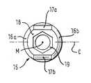
Translated fromKorean도 1은 본 발명의 일실시예에 따른 뼈 고정장치의 전개사시도이다.1 is an exploded perspective view of a bone fixing device according to an embodiment of the present invention.
도 2는 로드의 종축선을 따라 취한 도 1의 뼈 고정장치의 조립상태의 단면도이다.FIG. 2 is a cross-sectional view of the assembled state of the bone fixation device of FIG. 1 taken along the longitudinal axis of the rod. FIG.
도 3은 뼈 고정장치의 뼈 고정요소의 사시도이다.3 is a perspective view of a bone fixation element of the bone fixation device.
도 4는 도 3의 뼈 고정요소의 평면도이다.4 is a plan view of the bone fixation element of FIG.
도 5는 도 3의 뼈 고정요소의 부분측면도이다.5 is a partial side view of the bone fixation element of FIG. 3.
도 6은 도 3의 뼈 고정요소를 90°회전시킨 부분측면도이다.FIG. 6 is a partial side view of the bone fixing element of FIG. 3 rotated 90 °. FIG.
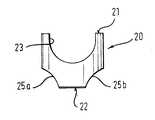
도 7은 뼈 고정장치의 압력요소의 평면도이다.7 is a plan view of the pressure element of the bone fixation device.
도 8은 뼈 고정장치의 압력요소의 측면도이다.8 is a side view of the pressure element of the bone fixation device.
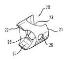
도 9는 뼈 고정장치의 압력요소의 저면으로부터의 사시도이다.9 is a perspective view from the bottom of the pressure element of the bone fixation device.
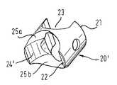
도 10은 도 9의 압력요소의 다른 사시도이다.10 is another perspective view of the pressure element of FIG. 9.
도 11은 뼈 고정장치의 압력요소의 저면도이다.11 is a bottom view of the pressure element of the bone fixation device.
도 12는 압력요소의 다른 실시예의 측면도이다.12 is a side view of another embodiment of a pressure element.
도 13은 도 12의 압력요소의 사시도이다.13 is a perspective view of the pressure element of FIG. 12.
도 14a 및 도 14b는 압력요소를 구비한 뼈 고정장치의 2가지 상이한 각 위치에서의 측면도이다.14A and 14B are side views at two different angular positions of the bone fixation device with pressure elements.
도 15는 압력요소를 구비한 뼈 고정요소의 사시도이다.15 is a perspective view of a bone fixation element with a pressure element.
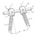
도 16은 로드에 본 발명에 따른 2개의 뼈 고정요소가 결합된 상태를 보여주는 도면이다.Figure 16 is a view showing a state in which the two bone fixing element according to the invention coupled to the rod.
도 17은 공지의 코스믹 포스티어리어 다이나믹 시스템을 보여주는 도면이다.17 illustrates a known cosmic postier dynamic system.
본 발명은 뼈에 고정될 고정요소 및 상기 고정요소에 연결될 로드를 수용하기 위한 수용부를 포함하는 뼈 고정장치에 관한 것이다. 상기 수용부는 종축선에 동축인 제1보어 및 제2보어를 구비하고, 상기 뼈 고정요소는 뼈 내에 삽입되는 제1단부 및 상기 제2보어 내에 설치될 수 있는 제2단부를 구비하고, 상기 고정요소는 상기 수용부의 종축선을 중심으로 제한된 각도범위 내에서 상기 수용부에 대해 상대이동이 가능하다. 상기 고정요소는 상기 수용부의 종축선을 횡절하는 방향의 단일 회전축을 중심으로 상기 수용부에 대해 피봇운동이 가능하다. 따라서, 상기 고정요소는 일 평면 내에서 상기 수용부에 대해 상대적 조정이 가능하다.The present invention relates to a bone fixation device comprising a fixation element to be fixed to a bone and a receiving portion for receiving a rod to be connected to the fixation element. The receiving portion has a first bore and a second bore coaxial to the longitudinal axis, the bone fixing element has a first end inserted into the bone and a second end that can be installed in the second bore, the fixing The element is movable relative to the receptacle within a limited angular range about the longitudinal axis of the receptacle. The fixing element is pivotable relative to the receptacle about a single axis of rotation in the direction transverse to the longitudinal axis of the receptacle. Thus, the fastening element is adjustable relative to the receiving portion in one plane.
미국특허 US 5,005,562에는 뼈에 고정될 나사 샤프트(threaded shaft) 또는 후크 및 상기 샤프트와 일체로 형성된 헤드를 구비하고, 상기 헤드는 로드를 수용하기 위한 U자형 리세스(recess)를 구비하는 뼈 고정장치가 개시되어 있다. 이 소위 단축(monoaxial) 뼈 고정장치는 부하에 대한 저항력이 크다. 그러나 상기 헤드부의 위치를 해부학적(anatomical) 조건에 맞도록 조절할 수 있는 가능성이 제한된 다.U.S. Pat.No. 5,005,562 has a threaded shaft or hook to be fixed to a bone and a head integrally formed with the shaft, the head having a U-shaped recess for receiving a rod. Is disclosed. This so-called monoaxial bone fixation device is highly resistant to load. However, the possibility of adjusting the position of the head portion to suit anatomical conditions is limited.
미국특허 US 5,443,467에는 로드를 수용하기 위한 수용부 및 나사 샤프트와 상기 수용부 내에 피봇운동이 가능하게 유지되는 구형 헤드를 구비하는 뼈 고정요소를 포함하는 뼈 고정장치가 개시되어 있다. 이 소위 다축(polyaxial) 뼈 고정요소를 이용하여, 상기 뼈 고정장치는 종축선을 중심으로 360°방향으로 수용부의 종축선을 중심으로 일반적으로 약 ±25에 이르는 범위까지 피봇운동할 수 있다. 따라서, 뼈 고정부재의 나사부를 뼈 내에 나사진입시킨 후에도, 로드를 수용하기 위해 고정요소에 대한 수용부의 방위를 조절할 수 있다. 상기 수용부의 방위를 해부학적 조건에 맞도록 조절하고, 상기 로드를 수용부에 삽입한 후에 뼈 고정장치는 고정된다.US Pat. No. 5,443,467 discloses a bone fixation device comprising a bone retaining element having a receptacle for accommodating a rod and a screw shaft and a spherical head which is pivotally retained within the receptacle. Using this so-called polyaxial bone fixation element, the bone fixation device can pivot in a range of about ± 25, generally about the longitudinal axis of the receptacle in a 360 ° direction about the longitudinal axis. Thus, even after threading the threaded portion of the bone fixation member into the bone, the orientation of the receiver relative to the fixation element can be adjusted to accommodate the rod. The orientation of the receptacle is adjusted to suit anatomical conditions, and the bone fixation device is secured after inserting the rod into the receptacle.
어떤 임상적 응용에 대해서, 예를 들면 경추(cervical vertebrae)는 그 크기가 작으므로 경추 영역에서는 흉추(thoracic vertebrae) 및 요추(lumbar vertebrae) 영역의 경우에 비해 특정 방향의 피봇운동 범위를 더 크게 할 필요가 있다. 미국특허 US 6,736,820B2에는 나사부 및 로드를 수용하는 수용부 내에 피봇운동이 가능하게 유지되는 헤드를 구비한 나사부재를 구비하는 뼈나사가 개시되어 있다. 상기 나사부재는 적어도 일측으로 확대된 각도로 피봇운동할 수 있다. 이것은 수용부의 측면(edge)을 비대칭 구조로 구성함으로써 달성된다. 그러나 상기 나사부재는 여전히 나사축선을 중심으로 360°각도범위 내의 모든 방향으로 피봇운동할 수 있다.For some clinical applications, for example, the cervical vertebrae is small in size, so in the cervical region, the range of pivotal movement in a particular direction will be greater than in the thoracic vertebrae and lumbar vertebrae regions. There is a need. U. S. Patent No. 6,736, 820 B2 discloses a bone screw having a screw member having a head which is capable of pivotal movement in a receiving portion for accommodating the thread portion and the rod. The screw member may pivot at an angle enlarged to at least one side. This is achieved by constructing the edge of the receptacle in an asymmetrical structure. However, the screw member can still pivot in all directions within the 360 ° angle range about the screw axis.
도 17에 도시된 코스믹 포스티어리어 다이나믹 시스템(Cosmic posterior dynamic system)에 개시된 뼈 고정장치는 로드(101)를 수용하는 수용부(100) 및 뼈나사(102)를 포함한다. 상기 뼈나사는 횡방향 핀(105)에 형성된 피봇축(103)을 중심으로 피봇운동이 가능하게 상기 수용부 내에 유지된다. 그러므로 뼈나사는 수용부의 종축선을 포함하는 일 평면 내에서 피봇운동이 가능하다. 상기 수용부에 대한 뼈나사의 상대위치는 고정될 수 없으므로 상기 뼈나사와 수용부는 항상 상대운동이 가능하다.The bone fixation device disclosed in the Cosmic posterior dynamic system shown in FIG. 17 includes a
본 발명의 목적은 조정이 가능하고, 부하 저항성(load resistance)이 개선되고, 조작이 용이하고, 뼈나사의 각도위치에 안전하게 고정할 수 있는 뼈 고정장치를 제공하는 것이다.It is an object of the present invention to provide a bone fixation device which is adjustable, load resistance is improved, is easy to operate, and which can be securely fixed at an angle position of a bone screw.
상기 목적은 청구항 1 또는 청구항 10에 따른 뼈 고정장치에 의해 달성된다. 추가의 개발 내용은 종속청구항에 기재되어 있다.This object is achieved by a bone fixation device according to
본 발명에 따른 뼈 고정장치는 단축 뼈 고정장치와 다축 뼈 고정장치의 장점을 조합한 것으로서, 수용부의 종축선을 포함하는 것이 바람직한 단일평면 내에서의 단일평면 조절(monoplanar adjustment)이 가능하다. 상기 고정요소는 수용부의 종축선을 횡절하는 하나의 회전축선을 중심으로 상기 수용부에 대해 상대적인 피봇운동이 가능하다. 따라서, 예를 들면, 뼈 고정요소에 대한 수용부의 상대위치를 단일평면 내에서만 조절할 수 있다. 상기 평면은, 예를 들면, 이 방향은 사용시 종종 시상면(sagittal plane)이 되는 로드와 평행인 방향으로 연장할 수 있고, 로드의 횡방향에서의 횡방향 운동은 방지된다. 또는, 상기 평면은 로드를 횡절하는 방향으 로 연장하거나 다른 방향으로 연장할 수 있다. 따라서, 전체 뼈 고정장치의 안정성이 향상된다.The bone fixation device according to the invention combines the advantages of a uniaxial bone fixation device and a multiaxial bone fixation device, which allows for monoplanar adjustment within a single plane which preferably includes the longitudinal axis of the receptacle. The fixing element is capable of pivoting relative to the receptacle about one axis of rotation transverse to the longitudinal axis of the receptacle. Thus, for example, the relative position of the receptacle relative to the bone fixation element can only be adjusted within a single plane. The plane may, for example, extend in a direction parallel to the rod, which in use is often a sagittal plane, and transverse motion in the transverse direction of the rod is prevented. Alternatively, the plane may extend in the direction transverse to the rod or in another direction. Thus, the stability of the entire bone fixation device is improved.
상기 수용부의 형상은 공지의 다축 뼈 고정장치용 수용부와 동일하게 구성할 수 있다. 따라서, 외과 수술에서의 실제적 필요에 따라 단축이나 다축의 뼈 고정장치를 사전 조립할 수 있으므로, 뼈 고정장치의 재고관리 비용을 감소시킬 수 있다.The shape of the accommodation portion can be configured in the same manner as the known accommodation portion for the multi-axis bone fixing device. Therefore, the short-term or multi-axis bone fixer can be pre-assembled according to the actual needs in the surgical operation, thereby reducing the inventory management cost of the bone fixer.
본 발명의 추가의 특징 및 장점은 첨부한 도면을 참조하여 이하에 기술한 발명의 상세한 설명에 의해 더욱 명확히 이해될 수 있다.Further features and advantages of the invention may be more clearly understood by the following detailed description of the invention with reference to the accompanying drawings.
도 1 및 도 2에 도시된 바와 같이, 본 뼈 고정장치는 실질적으로 원통형인, 제1단부(2) 및 이 제1단부의 반대편의 제2단부(3)를 구비하는 수용부(1)를 구비한다. 상기 양단부는 종축선(4)에 대해 수직을 이룬다. 상기 종축선(4)에 동축으로 보어(5)가 형성되어 있다. 이 보어는 상기 제1단부(2)로부터 상기 제2단부(3)까지 소정의 길이로 연장된다. 상기 제2단부(3)에는 상기 보어(5)의 직경보다 소직경을 가지는 개구(6)가 형성되어 있다. 상기 동축보어(5)는 상기 개구(6)를 향해 경사를 이루고 있다. 이 경사부(7)는 예를 들면 구형 또는 원추형으로 구성할 수 있다.As shown in FIGS. 1 and 2, the bone fixation device includes a receiving
상기 수용부(1)에는 또 U자형 리세스(recess; 8)가 구비되어 있다. 이 리세스는 상기 제1단부(2)로부터 상기 제2단부(3)를 향해 연장하여 상기 제2단부(3)로부터 소정의 거리만큼 이격된 위치에 이른다. 상기 U자형 리세스(8)에 의해 상기 제1단부(2)를 향해 연장하는 2개의 레그(9, 10)가 형성된다. 상기 수용부(1)의 상기 제1단부(2)에 인접한 레그(9, 10) 상에는 내부나사(11)가 구비되어 있다. 상기 U자형 리세스(8)는 로드(12)를 수용하기 위한 것으로서, 이 로드에는 복수의 뼈 고정장치가 연결된다.The
상기 뼈 고정장치는 또 뼈 고정요소를 구비한다. 이 뼈 고정요소는 뼈나사를 구비한 생크(14) 및 일단부의 헤드(15)를 구비한다. 도 3 내지 도 6에 도시된 바와 같이, 상기 헤드(15)는 상호 대향배치된 2부분(16a, 16b)을 구비한다. 상기 2부분은 중심이 헤드(15)의 중심과 일치하는 구형 외면을 가진다. 상기 2개의 대향배치된 구형 외면(16a, 16b) 사이에는 원통형 외면(17a, 17b)이 구비된다. 이 원통의 축선 C는 뼈 고정요소(13)의 종축선 L에 수직을 이룸과 동시에 상기 헤드의 중심 M을 관통한다. 상기 나사부(14)의 반대 측 부분의 헤드(15)에는 평면(18)이 구비되고, 이 평면(18)에는 나사체결 공구를 삽입하기 위한 리세스(19)가 형성되어 있다. 상기 원통형 외면(17a, 17b)의 원통의 반경은 구형 외면(16a, 16b)의 구의 반경보다 작다. 상기 나사부(14)의 직경은 수용부의 개구(16)의 직경보다 작다. 따라서, 상기 고정요소(13)는 수용부(1)의 제1단부(2)로부터 삽입될 수 있고, 상기 나사부(4)는 개구(6)를 통해 안내될 수 있고, 구형 외면(16a, 16b)은 수용부(1)의 경사면(7)에 접촉될 수 있다.The bone fixation device also has a bone fixation element. This bone fixation element has a
도 1 및 도 7 내지 도 15에 도시된 바와 같이, 상기 뼈 고정장치는 또 헤드(15)에 작용하여 수용부(1) 내에서의 헤드의 피봇운동을 제한하기 위한 압력요소(20)를 구비한다. 상기 압력요소(20)는 실질적으로 원통형이고, 제1단부(21) 및 제2단부(22)를 구비한다. 상기 압력요소(20)의 외경은 수용부(1)의 보어(5)의 내경에 비해 약간 작으므로 상기 압력요소(20)는 수용부(1) 내의 보어(5) 내에 슬라이 드 삽입할 수 있다. 상기 압력요소(20)의 제1단부(21)에는 제1의 부분 원통형 리세스(recess; 23)가 구비되어 있다. 이 리세스(23)의 치수는 로드(12)와 정확하게 맞물리는 치수이다. 상기 압력요소(20)의 제2단부(22)에는 제2의 부분 원통형 리세스(24)가 구비되어 있다. 이 리세스(24)의 원통축선은 상기 제1의 부분 원통형 리세스(23)의 원통축선에 수직을 이룬다.As shown in FIGS. 1 and 7 to 15, the bone fixation device also has a
상기 제2의 부분 원통형 리세스(24)의 반경은 본질적으로 헤드(15)의 원통형 외면(17a, 17b)의 반경과 동일하다. 상기 제2의 부분 원통형 리세스(24)의 폭은 헤드(15)의 원통형 외면(17a, 17b)의 폭과 동일하다. 따라서, 고정요소(13) 및 압력요소를 수용부(1) 내에 삽입했을 때, 상기 제2의 부분 원통형 리세스(24)는 원통형 외면(17a, 17b)의 적어도 일부분을 커버할 수 있다. 상기 압력요소(20)의 제2단부에는 또 2개의 대향하는 구형 리세스(25a, 25b)가 구비되어 있다. 이 구형 리세스는 상기 제2의 부분 원통형 리세스(24)의 양단부 상에 연장되어 있고, 그 직경은 예를 들면 헤드(15)의 대향하는 구형 표면(16a, 16b)의 직경과 동일하거나 크다. 따라서, 도 12a, 11b 및 13에 도시된 바와 같이, 상기 헤드(15)의 구형 표면(16a, 16b)은 압력요소(20)의해 커버되지 않는다.The radius of the second partial
또, 상기 압력요소(20)의 리세스(25a, 25b)가 형성된 양 외면상에는 크림프 보어(crimp bore; 26)가 형성되어 있다. 이 크림프 보어는 수용부(1)의 각 레그에 형성된 크림프 보어(27)와 정렬상태가 된다. 상기 크림프 보어(26, 27)는 수용부 내에서 압력요소(20)가 탈락하지 않도록 비고정상태로 압력요소를 예비조립하기 위해 형성한 것이다. 이러한 방식으로 상기 수용부에 대한 고정요소의 피봇운동면이 사전 결정된다.Crimp bores 26 are formed on both outer surfaces of the
또, 상기 압력요소(20)에는 상기 헤드(15)의 리세스(19)에 나사체결 공구를 접근시킬 수 있도록 동축보어(28)가 형성되어 있다.In addition, the
도 12 및 도 13은 압력요소의 변경 실시예를 도시한 것이다. 도시된 압력요소(20')는 도 7 내지 도 11의 압력요소에 비해 제1의 원통형 리세스(23)와 제2의 원통형 리세스(24')의 각 원통축이 평행하게 배열되어 있는 점이 다르다. 그 결과, 고정요소의 피봇운동을 위한 회전축선은 도 7 내지 도 11에 도시된 압력요소를 사용하는 경우에 비해 90°각도만큼 회전된다.12 and 13 show an alternative embodiment of the pressure element. The illustrated
도 1 및 도 2에 도시된 바와 같이, 상기 뼈 고정장치는 또 내부나사(inner screw; 30)를 구비한다. 이 내부나사는 레그(9, 10) 사이에 치합됨으로써 로드(12)를 고정함과 동시에 이 로드(12)를 통해 헤드(15) 상에 압력을 가한다.As shown in Figures 1 and 2, the bone fixation device also has an inner screw (30). The internal thread is engaged between the
장치 전체는 생체적합성 재료, 예를 들면 티타늄으로 제작한다.The whole device is made of a biocompatible material, for example titanium.
사용시, 먼저, 상기 고정요소(13)를 수용부(1) 내에 삽입하여, 나사 샤프트(14)를 수용부의 제2단부(3)의 개구(6)를 통과시킨 후 그 헤드(15)를 개구(6)에 인접한 경사부(7)에 지지시킨다. 다음에, 상기 압력요소(20)를 그 제2단부(22)가 상기 헤드를 향하도록 상기 수용부(1) 내에 삽입하고, 압력요소의 리세스(23)와 수용부(1)의 리세스(8)가 동축을 이루는 위치에서 상기 크림프 보어(26, 27)를 결합시킴으로써 비고정상태로 유지시킨다. 상기 원통형 표면(17a, 17b)은 상기 압력요소의 리세스(24)의 원통형 표면에 의해 적어도 부분적으로 커버된다. 이와 같은 방식으로 사전 조립한 고정요소(13)는 뼈 내에 나사진입된다.In use, first, the
이 상태에서 고정요소(13)는 수용부(1)에 대해 여전히 피봇운동이 가능하다. 그러나 그 피봇운동은 평면 P(즉, 수용부의 종축선(4)을 포함함과 동시에 수용부(1)의 경면대칭면을 형성하는 평면) 내에서 제한된 각도범위에서 실행된다. 본 실시예에 있어서, 상기 평면 P는 도 2에 도시된 단면이다. 상기 단일 평면 내에서의 피봇운동은 헤드(15)에 작용하는 압력요소(20)에 의해 달성된다. 헤드(15)의 원통형 외면(17a, 17b)과 제2의 부분 원통형 리세스(24)의 결합에 의해 고정요소(13)는 원통축선 C를 중심으로 한 피봇운동은 가능하고 다른 방향의 피봇운동은 방지된다. 따라서, 본 장치의 사용시 시상면, 즉 로드(12)의 종방향으로의 고정요소(13)에 대한 수용부의 위치조절은 가능한 반면 횡방향 조절, 즉 로드(12)에 대한 횡방향 조절은 방지된다. 상기 수용부(1)의 위치 조절 후, 로드(12)를 삽입하고, 레그(9, 10) 사이에 내부나사(30)를 나사결합하여 단단히 조이면 로드를 통해 압력요소(20)에 압력이 가해진다. 이 압력요소(20)는 헤드(15)에 압력을 가함으로써 헤드(15)를 고정시킨다. 따라서, 종축선(4)을 중심으로 한 고정요소(13)의 회전은 헤드(15)의 원통 표면과 압력요소의 폼피트 결합(form-fit cooperation)에 의해 방지되는 반면 단일 평면 내에서의 헤드의 각운동은 헤드(15)와 압력요소(20) 사이에 작용하는 마찰력에 의해 달성된다. 도 16은 2개의 뼈 고정장치(50, 50')가 로드(12)에 의해 연결된 것을 도시한 것이다. 제1의 뼈 고정장치(1)는 도 7 내지 도 11에 도시된 압력요소(20)를 구비한다. 고정요소(13)의 회전축은 로드의 축선 A에 대해 수직이고, 그 결과 수용부(1)의 종축선(4) 및 로드 축선 A에 의해 형성되는 일 평면 내에서의 조절이 가능하다. 제2의 뼈 고정장치(50')는 도 12 및 도 13에 도시된 압력요소(20')를 구비한다. 고정요소(13)의 회전축은 로드 축선 A에 대해 평행이고, 그 결과 로드 축선 A에 대해 수직이고 수용부의 종축선(4)을 포함하는 단일 평면 내에서의 고정요소(13)의 조절이 가능하다.In this state, the fixing
도 14a, 14b, 15 및 16에 도시된 바와 같이, 본 발명에 따른 뼈 고정장치는 단일 평면 내에서의 조절, 환언하면, 단일 회전축선을 중심으로 한 회전이 가능하다. 따라서, 고정요소는 단일평면 연결구조(monoplanar manner)로 수용부에 연결된다. 본 뼈 고정장치는 종축선을 중심으로 360°범위 내에서 피봇운동이 가능한 다축식 뼈 고정장치에 비해 안정성이 높다. 본 뼈 고정장치는 부하에 대한 저항력이 향상되고, 특수한 임상 적용을 위해 충분한 정도의 수용부의 위치조절이 가능하다. 적절한 압력요소를 사용하면, 실제의 해부학적 조건에 따라 로드에 대해 원하는 평면 내에서의 조절이 가능한 뼈 고정장치를 조립할 수 있다.As shown in Figures 14a, 14b, 15 and 16, the bone fixation device according to the present invention can be adjusted in a single plane, in other words, rotation about a single axis of rotation. The fastening elements are thus connected to the receptacle in a monoplanar manner. The bone fixation device is more stable than the multi-axis bone fixation device that can pivot within the 360 ° range around the longitudinal axis. The bone fixation device has improved load resistance and can be repositioned to a sufficient extent for specific clinical applications. Using an appropriate pressure element, it is possible to assemble a bone fixation that can be adjusted in the desired plane for the rod according to the actual anatomical conditions.
본 발명은 전술한 실시예에 한정되지 않고, 다양한 변경이 가능하다. 상기 압력요소의 제1 및 제2의 원통형 리세스의 2개의 원통축선의 방위는 상호 변화시키는 것이 가능하다.The present invention is not limited to the embodiment described above, and various modifications are possible. The orientations of the two cylindrical axes of the first and second cylindrical recesses of the pressure element can be changed mutually.
상기 압력요소의 부분 원통형 리세스(23)는 생략할 수 있다. 즉, 압력요소의 제1단부(21)를 평면으로 형성할 수 있다. 이 경우, 제2의 부분 원통형 리세스가 임의의 방향으로 지향되도록 상기 압력요소를 수용부 내에서 지향시킬 수 있다.The partial
상기 헤드(15)의 표면(16a, 16b)은 반드시 구형으로 형성할 필요는 없고, 평평한 형상으로 형성할 수도 있다.The
상기 고정요소의 피봇운동이 가능한 단일 평면 내에 반드시 종축선이 포함될 필요는 없고, 상기 단일 평면은 종축선에 평행하게 연장시킬 수 있다.The longitudinal axis does not necessarily need to be included in a single plane in which the pivoting motion of the stationary element is possible, and the single plane may extend parallel to the longitudinal axis.
상기 수용부는 개구(6)의 가장자리를 비대칭으로 형성하여 상기 종축선의 일측으로의 피봇운동 각도를 타측으로의 피봇운동 각도에 비해 크게 할 수 있다. 이 비대칭형 피봇운동은 다른 수단에 의해서도 달성할 수 있다.The accommodating portion may form an edge of the opening 6 asymmetrically to increase the pivot movement angle to one side of the longitudinal axis compared with the pivot movement angle to the other side. This asymmetrical pivot movement can also be achieved by other means.
도면에 도시된 실시예에 있어서, 압력은 로드(12)를 통해 압력요소(20) 상에 가해지고, 이 압력요소는 헤드를 가압한다. 그러나 압력요소(20)를 통한 헤드(15)의 로킹을 로드(12)를 통한 로킹과 분리시킬 수도 있다. 이를 위해, 압력요소(20)의 리세스(23)에 삽입된 로드(12)의 상측으로 연장하는 레그를 형성한다. 그 결과, 별도의 내부나사를 통해 상기 레그에 압력을 가하고, 이 별도의 내부나사의 내측에는 상기 로드에 압력을 가하는 내부나사(30)가 내재된다.In the embodiment shown in the figure, pressure is exerted on the
다른 변경 실시예에 있어서, 헤드를 제2단부로부터 수용부(1) 내에 삽입할 수 있는 구성이 가능하다. 이 경우, 개구(6)는 상기 헤드를 도입하는데 충분한 크기로 형성해야 하고, 헤드의 탈락을 방지하는 수단을 설치해 주어야 한다.In another alternative embodiment, a configuration is possible in which the head can be inserted into the
다른 변경 실시예에 있어서, 수용부의 하측 개구(6)에 상기 고정요소의 샤프트(14)의 나사와 치합하는 나사를 형성한다. 이 경우, 고정요소(13)의 나사 샤프트(14)는 상기 개구와 치합함과 동시에 뼈 내에 치합할 수 있다. 상기 나사 샤프트의 직경은 제1 보어(5)의 직경과 동일하게 형성할 수 있다.In a further alternative embodiment, the lower opening 6 of the receptacle forms a screw that engages with the screw of the
상기 나사 샤프트(14) 대신 네일(nails) 또는 훅크(hooks)와 같은 다른 뼈 고정수단으로 구성하는 것도 가능하다.Instead of the
본 뼈 고정장치는 수술 전에 미리 조립할 필요없이, 수술 중에 조립할 수 있 다.The bone fixation device can be assembled during surgery, without the need for prior assembly.
본 발명에 따르면 조정이 가능하고, 부하 저항성이 개선되고, 조작이 용이하고, 뼈나사의 각도위치에 안전하게 고정할 수 있는 뼈 고정장치를 제공할 수 있다.According to the present invention, it is possible to provide a bone fixing device which can be adjusted, load resistance is improved, easy to operate, and can be securely fixed at an angle position of a bone screw.
Claims (10)
Translated fromKoreanApplications Claiming Priority (4)
| Application Number | Priority Date | Filing Date | Title |
|---|---|---|---|
| US72603205P | 2005-10-12 | 2005-10-12 | |
| EP05022263.7 | 2005-10-12 | ||
| EP05022263AEP1774919B1 (en) | 2005-10-12 | 2005-10-12 | Poly-axial screw pivotable in a single plane |
| US60/726,032 | 2005-10-12 |
Publications (2)
| Publication Number | Publication Date |
|---|---|
| KR20070040720A KR20070040720A (en) | 2007-04-17 |
| KR101267581B1true KR101267581B1 (en) | 2013-05-23 |
Family
ID=35739310
Family Applications (1)
| Application Number | Title | Priority Date | Filing Date |
|---|---|---|---|
| KR1020060097933AExpired - Fee RelatedKR101267581B1 (en) | 2005-10-12 | 2006-10-09 | Bone anchoring device |
Country Status (8)
| Country | Link |
|---|---|
| US (4) | US7749258B2 (en) |
| EP (1) | EP1774919B1 (en) |
| JP (1) | JP4994773B2 (en) |
| KR (1) | KR101267581B1 (en) |
| CN (1) | CN1965769B (en) |
| DE (1) | DE602005009202D1 (en) |
| ES (1) | ES2313182T3 (en) |
| TW (1) | TWI379657B (en) |
Families Citing this family (165)
| Publication number | Priority date | Publication date | Assignee | Title |
|---|---|---|---|---|
| US7833250B2 (en) | 2004-11-10 | 2010-11-16 | Jackson Roger P | Polyaxial bone screw with helically wound capture connection |
| US10729469B2 (en) | 2006-01-09 | 2020-08-04 | Roger P. Jackson | Flexible spinal stabilization assembly with spacer having off-axis core member |
| US7862587B2 (en) | 2004-02-27 | 2011-01-04 | Jackson Roger P | Dynamic stabilization assemblies, tool set and method |
| US8353932B2 (en)* | 2005-09-30 | 2013-01-15 | Jackson Roger P | Polyaxial bone anchor assembly with one-piece closure, pressure insert and plastic elongate member |
| US8292926B2 (en) | 2005-09-30 | 2012-10-23 | Jackson Roger P | Dynamic stabilization connecting member with elastic core and outer sleeve |
| US10258382B2 (en) | 2007-01-18 | 2019-04-16 | Roger P. Jackson | Rod-cord dynamic connection assemblies with slidable bone anchor attachment members along the cord |
| US8876868B2 (en) | 2002-09-06 | 2014-11-04 | Roger P. Jackson | Helical guide and advancement flange with radially loaded lip |
| WO2006052796A2 (en) | 2004-11-10 | 2006-05-18 | Jackson Roger P | Helical guide and advancement flange with break-off extensions |
| US6716214B1 (en) | 2003-06-18 | 2004-04-06 | Roger P. Jackson | Polyaxial bone screw with spline capture connection |
| US7621918B2 (en) | 2004-11-23 | 2009-11-24 | Jackson Roger P | Spinal fixation tool set and method |
| US7377923B2 (en) | 2003-05-22 | 2008-05-27 | Alphatec Spine, Inc. | Variable angle spinal screw assembly |
| US7776067B2 (en) | 2005-05-27 | 2010-08-17 | Jackson Roger P | Polyaxial bone screw with shank articulation pressure insert and method |
| US8137386B2 (en) | 2003-08-28 | 2012-03-20 | Jackson Roger P | Polyaxial bone screw apparatus |
| US7967850B2 (en) | 2003-06-18 | 2011-06-28 | Jackson Roger P | Polyaxial bone anchor with helical capture connection, insert and dual locking assembly |
| US8377102B2 (en) | 2003-06-18 | 2013-02-19 | Roger P. Jackson | Polyaxial bone anchor with spline capture connection and lower pressure insert |
| US8398682B2 (en) | 2003-06-18 | 2013-03-19 | Roger P. Jackson | Polyaxial bone screw assembly |
| US7766915B2 (en) | 2004-02-27 | 2010-08-03 | Jackson Roger P | Dynamic fixation assemblies with inner core and outer coil-like member |
| US8257398B2 (en) | 2003-06-18 | 2012-09-04 | Jackson Roger P | Polyaxial bone screw with cam capture |
| US8926670B2 (en) | 2003-06-18 | 2015-01-06 | Roger P. Jackson | Polyaxial bone screw assembly |
| US11419642B2 (en) | 2003-12-16 | 2022-08-23 | Medos International Sarl | Percutaneous access devices and bone anchor assemblies |
| US7179261B2 (en) | 2003-12-16 | 2007-02-20 | Depuy Spine, Inc. | Percutaneous access devices and bone anchor assemblies |
| US7527638B2 (en) | 2003-12-16 | 2009-05-05 | Depuy Spine, Inc. | Methods and devices for minimally invasive spinal fixation element placement |
| US7678137B2 (en) | 2004-01-13 | 2010-03-16 | Life Spine, Inc. | Pedicle screw constructs for spine fixation systems |
| US7160300B2 (en) | 2004-02-27 | 2007-01-09 | Jackson Roger P | Orthopedic implant rod reduction tool set and method |
| US8152810B2 (en) | 2004-11-23 | 2012-04-10 | Jackson Roger P | Spinal fixation tool set and method |
| US11241261B2 (en) | 2005-09-30 | 2022-02-08 | Roger P Jackson | Apparatus and method for soft spinal stabilization using a tensionable cord and releasable end structure |
| JP2007525274A (en) | 2004-02-27 | 2007-09-06 | ロジャー・ピー・ジャクソン | Orthopedic implant rod reduction instrument set and method |
| US7901435B2 (en)* | 2004-05-28 | 2011-03-08 | Depuy Spine, Inc. | Anchoring systems and methods for correcting spinal deformities |
| US20060058788A1 (en)* | 2004-08-27 | 2006-03-16 | Hammer Michael A | Multi-axial connection system |
| US8951290B2 (en) | 2004-08-27 | 2015-02-10 | Blackstone Medical, Inc. | Multi-axial connection system |
| US7651502B2 (en) | 2004-09-24 | 2010-01-26 | Jackson Roger P | Spinal fixation tool set and method for rod reduction and fastener insertion |
| US8926672B2 (en) | 2004-11-10 | 2015-01-06 | Roger P. Jackson | Splay control closure for open bone anchor |
| US8444681B2 (en) | 2009-06-15 | 2013-05-21 | Roger P. Jackson | Polyaxial bone anchor with pop-on shank, friction fit retainer and winged insert |
| US8308782B2 (en) | 2004-11-23 | 2012-11-13 | Jackson Roger P | Bone anchors with longitudinal connecting member engaging inserts and closures for fixation and optional angulation |
| US7875065B2 (en) | 2004-11-23 | 2011-01-25 | Jackson Roger P | Polyaxial bone screw with multi-part shank retainer and pressure insert |
| US9216041B2 (en) | 2009-06-15 | 2015-12-22 | Roger P. Jackson | Spinal connecting members with tensioned cords and rigid sleeves for engaging compression inserts |
| US9980753B2 (en) | 2009-06-15 | 2018-05-29 | Roger P Jackson | pivotal anchor with snap-in-place insert having rotation blocking extensions |
| WO2006057837A1 (en) | 2004-11-23 | 2006-06-01 | Jackson Roger P | Spinal fixation tool attachment structure |
| US9168069B2 (en) | 2009-06-15 | 2015-10-27 | Roger P. Jackson | Polyaxial bone anchor with pop-on shank and winged insert with lower skirt for engaging a friction fit retainer |
| US10076361B2 (en) | 2005-02-22 | 2018-09-18 | Roger P. Jackson | Polyaxial bone screw with spherical capture, compression and alignment and retention structures |
| US7901437B2 (en) | 2007-01-26 | 2011-03-08 | Jackson Roger P | Dynamic stabilization member with molded connection |
| US7955358B2 (en) | 2005-09-19 | 2011-06-07 | Albert Todd J | Bone screw apparatus, system and method |
| US8105368B2 (en) | 2005-09-30 | 2012-01-31 | Jackson Roger P | Dynamic stabilization connecting member with slitted core and outer sleeve |
| GB0521582D0 (en) | 2005-10-22 | 2005-11-30 | Depuy Int Ltd | An implant for supporting a spinal column |
| GB0600662D0 (en) | 2006-01-13 | 2006-02-22 | Depuy Int Ltd | Spinal support rod kit |
| US8348952B2 (en) | 2006-01-26 | 2013-01-08 | Depuy International Ltd. | System and method for cooling a spinal correction device comprising a shape memory material for corrective spinal surgery |
| ES2334811T3 (en)* | 2006-11-17 | 2010-03-16 | Biedermann Motech Gmbh | OSEO ANCHORAGE DEVICE. |
| CA2670988C (en) | 2006-12-08 | 2014-03-25 | Roger P. Jackson | Tool system for dynamic spinal implants |
| US8636783B2 (en)* | 2006-12-29 | 2014-01-28 | Zimmer Spine, Inc. | Spinal stabilization systems and methods |
| WO2008082836A1 (en)* | 2006-12-29 | 2008-07-10 | Abbott Spine Inc. | Spinal stabilization systems and methods |
| US8366745B2 (en) | 2007-05-01 | 2013-02-05 | Jackson Roger P | Dynamic stabilization assembly having pre-compressed spacers with differential displacements |
| US8475498B2 (en) | 2007-01-18 | 2013-07-02 | Roger P. Jackson | Dynamic stabilization connecting member with cord connection |
| US10792074B2 (en) | 2007-01-22 | 2020-10-06 | Roger P. Jackson | Pivotal bone anchor assemly with twist-in-place friction fit insert |
| US8167912B2 (en) | 2007-02-27 | 2012-05-01 | The Center for Orthopedic Research and Education, Inc | Modular pedicle screw system |
| US7967849B2 (en)* | 2007-04-06 | 2011-06-28 | Warsaw Orthopedic, Inc. | Adjustable multi-axial spinal coupling assemblies |
| US10383660B2 (en) | 2007-05-01 | 2019-08-20 | Roger P. Jackson | Soft stabilization assemblies with pretensioned cords |
| US8979904B2 (en) | 2007-05-01 | 2015-03-17 | Roger P Jackson | Connecting member with tensioned cord, low profile rigid sleeve and spacer with torsion control |
| US8197518B2 (en) | 2007-05-16 | 2012-06-12 | Ortho Innovations, Llc | Thread-thru polyaxial pedicle screw system |
| US7942911B2 (en) | 2007-05-16 | 2011-05-17 | Ortho Innovations, Llc | Polyaxial bone screw |
| US7942909B2 (en) | 2009-08-13 | 2011-05-17 | Ortho Innovations, Llc | Thread-thru polyaxial pedicle screw system |
| US7947065B2 (en)* | 2008-11-14 | 2011-05-24 | Ortho Innovations, Llc | Locking polyaxial ball and socket fastener |
| US7942910B2 (en) | 2007-05-16 | 2011-05-17 | Ortho Innovations, Llc | Polyaxial bone screw |
| US7951173B2 (en) | 2007-05-16 | 2011-05-31 | Ortho Innovations, Llc | Pedicle screw implant system |
| US8048128B2 (en)* | 2007-06-05 | 2011-11-01 | Spartek Medical, Inc. | Revision system and method for a dynamic stabilization and motion preservation spinal implantation system and method |
| DE602007007466D1 (en)* | 2007-07-20 | 2010-08-12 | Biedermann Motech Gmbh | Bone anchoring device |
| FR2920959B1 (en)* | 2007-09-17 | 2010-09-10 | Clariance | VERTEBRAL ANCHORING DEVICE. |
| US8038701B2 (en)* | 2007-10-22 | 2011-10-18 | K2M, Inc. | Uni-planar, taper lock bone screw |
| GB0720762D0 (en) | 2007-10-24 | 2007-12-05 | Depuy Spine Sorl | Assembly for orthopaedic surgery |
| US8007522B2 (en) | 2008-02-04 | 2011-08-30 | Depuy Spine, Inc. | Methods for correction of spinal deformities |
| US7857835B2 (en) | 2008-02-22 | 2010-12-28 | Depuy Spine, Inc. | Method and system for trans-lamina spinal fixation |
| WO2009124196A2 (en)* | 2008-04-03 | 2009-10-08 | Life Spine, Inc. | Top loading polyaxial spine screw assembly with one step lockup |
| AU2009261934B2 (en)* | 2008-06-27 | 2014-09-04 | K2M, Inc. | System and method for performing spinal surgery |
| TR201103565T2 (en)* | 2008-07-25 | 2011-08-22 | Hays Sa�Lik �R�Nler� �� Ve Di� T�Caret Hayvancilik Ltd.�T�. | Posterior dynamic screw. |
| AU2010260521C1 (en) | 2008-08-01 | 2013-08-01 | Roger P. Jackson | Longitudinal connecting member with sleeved tensioned cords |
| ES2394670T3 (en) | 2008-10-08 | 2013-02-04 | Biedermann Technologies Gmbh & Co. Kg | Elongated implant device and vertebral stabilization device |
| US8075603B2 (en) | 2008-11-14 | 2011-12-13 | Ortho Innovations, Llc | Locking polyaxial ball and socket fastener |
| ES2548580T3 (en) | 2009-02-20 | 2015-10-19 | Biedermann Technologies Gmbh & Co. Kg | Receiving part for housing a rod for coupling to a bone anchoring element and bone anchoring device that includes such receiving part |
| US8998959B2 (en) | 2009-06-15 | 2015-04-07 | Roger P Jackson | Polyaxial bone anchors with pop-on shank, fully constrained friction fit retainer and lock and release insert |
| US9668771B2 (en) | 2009-06-15 | 2017-06-06 | Roger P Jackson | Soft stabilization assemblies with off-set connector |
| CN103826560A (en) | 2009-06-15 | 2014-05-28 | 罗杰.P.杰克逊 | Polyaxial Bone Anchor with Socket Stem and Winged Inserts with Friction Fit Compression Collars |
| US11229457B2 (en) | 2009-06-15 | 2022-01-25 | Roger P. Jackson | Pivotal bone anchor assembly with insert tool deployment |
| EP2485654B1 (en) | 2009-10-05 | 2021-05-05 | Jackson P. Roger | Polyaxial bone anchor with non-pivotable retainer and pop-on shank, some with friction fit |
| US8430917B2 (en)* | 2009-10-30 | 2013-04-30 | Warsaw Orthopedic, Inc. | Bone engaging implant with adjustment saddle |
| US8449578B2 (en)* | 2009-11-09 | 2013-05-28 | Ebi, Llc | Multiplanar bone anchor system |
| US9044272B2 (en) | 2009-11-09 | 2015-06-02 | Ebi, Llc | Multiplanar bone anchor system |
| US8986349B1 (en) | 2009-11-11 | 2015-03-24 | Nuvasive, Inc. | Systems and methods for correcting spinal deformities |
| US8419778B2 (en) | 2010-01-15 | 2013-04-16 | Ebi, Llc | Uniplanar bone anchor system |
| US8647370B2 (en)* | 2010-01-15 | 2014-02-11 | Ebi, Llc | Uniplanar bone anchor system |
| US20110196430A1 (en)* | 2010-02-10 | 2011-08-11 | Walsh David A | Spinal fixation assembly with intermediate element |
| WO2011106339A1 (en) | 2010-02-23 | 2011-09-01 | K2M, Inc. | Polyaxial bone screw assembly |
| WO2011127065A1 (en)* | 2010-04-06 | 2011-10-13 | Seaspine, Inc. | System and methods for correcting spinal deformities |
| DE102010028423B4 (en) | 2010-04-30 | 2016-04-14 | Kilian Kraus | Pedicle screw and device for stabilizing the spine |
| US12383311B2 (en) | 2010-05-14 | 2025-08-12 | Roger P. Jackson | Pivotal bone anchor assembly and method for use thereof |
| US8882817B2 (en) | 2010-08-20 | 2014-11-11 | K2M, Inc. | Spinal fixation system |
| AU2014200455B2 (en)* | 2010-08-20 | 2014-12-18 | K2M, Inc. | Spinal Fixation System |
| US9393049B2 (en) | 2010-08-20 | 2016-07-19 | K2M, Inc. | Spinal fixation system |
| WO2012030712A1 (en) | 2010-08-30 | 2012-03-08 | Zimmer Spine, Inc. | Polyaxial pedicle screw |
| AU2011299558A1 (en) | 2010-09-08 | 2013-05-02 | Roger P. Jackson | Dynamic stabilization members with elastic and inelastic sections |
| AU2011324058A1 (en) | 2010-11-02 | 2013-06-20 | Roger P. Jackson | Polyaxial bone anchor with pop-on shank and pivotable retainer |
| EP2659845A1 (en)* | 2010-12-27 | 2013-11-06 | Biedermann Technologies GmbH & Co. KG | Polyaxial bone anchoring device |
| CN102551856B (en)* | 2011-01-24 | 2014-07-09 | 上海锐植医疗器械有限公司 | Internal fixing system capable of dilating wound of spinal column in self-rotation manner |
| CN102068304B (en)* | 2011-01-26 | 2013-01-02 | 邱勇 | Pedicle screw |
| CN102090920A (en)* | 2011-03-21 | 2011-06-15 | 丁亮华 | Universal micrometer pedicle screw |
| JP5865479B2 (en) | 2011-03-24 | 2016-02-17 | ロジャー・ピー・ジャクソン | Multiaxial bone anchor with compound joint and pop-mounted shank |
| US9072551B2 (en)* | 2011-06-09 | 2015-07-07 | Christel Paroth | Surgical instrument |
| DE102011050996A1 (en)* | 2011-06-09 | 2012-12-13 | Zbigniew Combrowski | Surgical instrument |
| US9005249B2 (en) | 2011-07-11 | 2015-04-14 | Life Spine, Inc. | Spinal rod connector assembly |
| US11103286B2 (en)* | 2011-07-15 | 2021-08-31 | Globus Medical, Inc. | Orthopedic fixation devices and methods of installation thereof |
| US9295501B2 (en) | 2011-08-02 | 2016-03-29 | Blackstone Medical, Inc. | Bayonet counter-torque wrench |
| EP2559389B1 (en)* | 2011-08-18 | 2013-04-03 | Biedermann Technologies GmbH & Co. KG | Polyaxial bone anchoring device |
| EP2604204B1 (en) | 2011-12-13 | 2014-10-01 | Biedermann Technologies GmbH & Co. KG | Monoplanar bone anchoring device with selectable pivot plane |
| EP2606841B1 (en)* | 2011-12-23 | 2016-03-09 | Biedermann Technologies GmbH & Co. KG | Polyaxial bone anchoring device |
| US8911479B2 (en) | 2012-01-10 | 2014-12-16 | Roger P. Jackson | Multi-start closures for open implants |
| CN102641148A (en)* | 2012-04-16 | 2012-08-22 | 黄孟锋 | Bone fixing device |
| ES2696676T3 (en) | 2012-09-04 | 2019-01-17 | Trigueros Ignacio Sanpera | System for a three-dimensional global correction of the curvatures of the column |
| US9782204B2 (en) | 2012-09-28 | 2017-10-10 | Medos International Sarl | Bone anchor assemblies |
| US8911478B2 (en) | 2012-11-21 | 2014-12-16 | Roger P. Jackson | Splay control closure for open bone anchor |
| CN103070725A (en)* | 2013-01-14 | 2013-05-01 | 北京市富乐科技开发有限公司 | Minimally invasive extension jib pedicle screw |
| US10058354B2 (en) | 2013-01-28 | 2018-08-28 | Roger P. Jackson | Pivotal bone anchor assembly with frictional shank head seating surfaces |
| EP2764840B1 (en) | 2013-02-11 | 2017-05-03 | Biedermann Technologies GmbH & Co. KG | Coupling assembly for coupling a rod to a bone anchoring element and bone anchoring device with such a coupling assembly |
| US8852239B2 (en) | 2013-02-15 | 2014-10-07 | Roger P Jackson | Sagittal angle screw with integral shank and receiver |
| US20140277153A1 (en) | 2013-03-14 | 2014-09-18 | DePuy Synthes Products, LLC | Bone Anchor Assemblies and Methods With Improved Locking |
| US9724145B2 (en) | 2013-03-14 | 2017-08-08 | Medos International Sarl | Bone anchor assemblies with multiple component bottom loading bone anchors |
| US9259247B2 (en) | 2013-03-14 | 2016-02-16 | Medos International Sarl | Locking compression members for use with bone anchor assemblies and methods |
| US9775660B2 (en) | 2013-03-14 | 2017-10-03 | DePuy Synthes Products, Inc. | Bottom-loading bone anchor assemblies and methods |
| US10342582B2 (en) | 2013-03-14 | 2019-07-09 | DePuy Synthes Products, Inc. | Bone anchor assemblies and methods with improved locking |
| WO2014169189A1 (en) | 2013-04-12 | 2014-10-16 | Alphatec Spine, Inc. | Uniplanar screw assembly and methods of use |
| US9453526B2 (en) | 2013-04-30 | 2016-09-27 | Degen Medical, Inc. | Bottom-loading anchor assembly |
| US9526529B2 (en) | 2013-09-25 | 2016-12-27 | Blackstone Medical, Inc. | Bone screw systems with pressure caps having biasing members |
| DE102013110796A1 (en) | 2013-09-30 | 2015-04-02 | Z-Medical Gmbh & Co. Kg | Surgical instrument |
| US9480501B2 (en)* | 2013-10-21 | 2016-11-01 | Blackstone Medical, Inc. | Modular pedicle screw |
| US9566092B2 (en) | 2013-10-29 | 2017-02-14 | Roger P. Jackson | Cervical bone anchor with collet retainer and outer locking sleeve |
| US12016595B2 (en)* | 2013-11-22 | 2024-06-25 | Spinal Balance, Inc. | Poly-axial pedicle screw assembly and packaging therefor |
| US9980758B2 (en) | 2013-11-27 | 2018-05-29 | Blackstone Medical, Inc. | Minimally invasive counter-torque wrench system |
| US9717533B2 (en) | 2013-12-12 | 2017-08-01 | Roger P. Jackson | Bone anchor closure pivot-splay control flange form guide and advancement structure |
| US9451993B2 (en) | 2014-01-09 | 2016-09-27 | Roger P. Jackson | Bi-radial pop-on cervical bone anchor |
| ES2611014T3 (en)* | 2014-01-13 | 2017-05-04 | Biedermann Technologies Gmbh & Co. Kg | Coupling assembly for coupling a rod to a bone anchoring element, and polyaxial bone anchoring device |
| US10918419B2 (en) | 2014-04-01 | 2021-02-16 | K2M, Inc. | Spinal fixation device |
| US9549765B2 (en) | 2014-04-03 | 2017-01-24 | Zimmer Spine, Inc. | Uniplanar bone screw |
| US20150313647A1 (en) | 2014-04-30 | 2015-11-05 | Ignacio Sanpera Trigueros | System for correction of the spine curvatures |
| US9597119B2 (en) | 2014-06-04 | 2017-03-21 | Roger P. Jackson | Polyaxial bone anchor with polymer sleeve |
| US10064658B2 (en) | 2014-06-04 | 2018-09-04 | Roger P. Jackson | Polyaxial bone anchor with insert guides |
| FR3027209B1 (en)* | 2014-10-20 | 2016-11-25 | Safe Orthopaedics | MULTI-AXIAL VERTEBRAL ANCHORING DEVICE FOR RESTRICTING A VERTEBRA |
| CN106037994B (en)* | 2016-07-08 | 2018-09-18 | 北京大学人民医院 | Hipbone dummy |
| CN106073948B (en)* | 2016-07-08 | 2018-02-02 | 北京大学人民医院 | Iliac prosthesis |
| US10575878B2 (en)* | 2016-07-21 | 2020-03-03 | Warsaw Orthopedic, Inc. | Spinal implant system and methods of use |
| CA3043217A1 (en) | 2016-11-18 | 2018-05-24 | Javier Garcia-Bengochea | Implants and instruments for enhancing vertebral alignment and sagittal balance |
| WO2018186887A1 (en)* | 2017-04-07 | 2018-10-11 | Facet-Link Inc. | Spinal fixation element and stabilization system |
| US10610265B1 (en) | 2017-07-31 | 2020-04-07 | K2M, Inc. | Polyaxial bone screw with increased angulation |
| US10743918B2 (en)* | 2018-06-27 | 2020-08-18 | Texas Scottish Rite Hospital For Children | External fixation connection rod with female attachment |
| US11596449B2 (en) | 2018-09-13 | 2023-03-07 | Roger P. Jackson | Pivotal bone anchor assembly with modular receiver and universal shank head |
| WO2020097691A1 (en)* | 2018-11-16 | 2020-05-22 | Southern Cross Patents Pty Ltd | Pedicle screws |
| US20220160400A1 (en)* | 2019-03-12 | 2022-05-26 | Carbofix Spine Inc. | Composite material spinal implant |
| DE102019116368A1 (en) | 2019-06-17 | 2020-12-17 | Aesculap Ag | Partially blocked pedicle screw |
| DE102019116374A1 (en) | 2019-06-17 | 2020-12-17 | Aesculap Ag | Partially blocked pedicle screw II |
| WO2021263088A1 (en) | 2020-06-26 | 2021-12-30 | K2M, Inc. | Modular head assembly |
| US11311316B2 (en)* | 2020-09-04 | 2022-04-26 | Warsaw Orthopedic, Inc. | Spinal implant system and methods of use |
| WO2022108875A1 (en) | 2020-11-19 | 2022-05-27 | K2M, Inc. | Modular head assembly for spinal fixation |
| WO2022184797A1 (en) | 2021-03-05 | 2022-09-09 | Medos International Sarl | Selectively locking polyaxial screw |
| US12364515B2 (en) | 2021-03-05 | 2025-07-22 | Medos International Sàrl | Multi-feature polyaxial screw |
| US11751915B2 (en) | 2021-07-09 | 2023-09-12 | Roger P. Jackson | Modular spinal fixation system with bottom-loaded universal shank heads |
| US12053209B2 (en) | 2022-01-18 | 2024-08-06 | Roger P. Jackson | Spinal fixation systems with modular receiver and ring retainer sub-assemblies for connecting with universal shank heads |
| US12414801B2 (en) | 2022-11-03 | 2025-09-16 | Roger P. Jackson | Spinal fixation system with modular receiver sub-assemblies for connecting with bi-spherical universal shank heads |
| EP4437983A1 (en) | 2023-03-30 | 2024-10-02 | Biedermann Technologies GmbH & Co. KG | Coupling device for coupling a rod to a bone anchor and system of such a coupling device and at least two bone anchors |
| EP4570198A1 (en) | 2023-12-15 | 2025-06-18 | Biedermann Technologies GmbH & Co. KG | Coupling device for coupling a rod to a bone anchor and system of such a coupling device and at least two bone anchors |
Citations (3)
| Publication number | Priority date | Publication date | Assignee | Title |
|---|---|---|---|---|
| US5181917A (en) | 1990-06-19 | 1993-01-26 | Chaim Rogozinski | System and method for instrumentation of the spine in the treatment of spinal deformities |
| US5443467A (en) | 1993-03-10 | 1995-08-22 | Biedermann Motech Gmbh | Bone screw |
| JP2005506128A (en) | 2001-10-15 | 2005-03-03 | リード、ゲーリー、ジェイ | Stabilizing device and method for orthopedics |
Family Cites Families (16)
| Publication number | Priority date | Publication date | Assignee | Title |
|---|---|---|---|---|
| US4500586A (en)* | 1981-01-29 | 1985-02-19 | Bussey Harry Jun | Billowed filling elements for packaging |
| FR2633177B1 (en)* | 1988-06-24 | 1991-03-08 | Fabrication Materiel Orthopedi | IMPLANT FOR A SPINAL OSTEOSYNTHESIS DEVICE, ESPECIALLY IN TRAUMATOLOGY |
| US5595811A (en)* | 1992-01-31 | 1997-01-21 | Stout, Jr.; William A. | Packaging material |
| DE4425357C2 (en)* | 1994-07-18 | 1996-07-04 | Harms Juergen | Anchoring element |
| CN1142746C (en)* | 1996-12-12 | 2004-03-24 | 库尔斯恩蒂斯股份公司 | Device for connecting longitudinal support to pedicle screw |
| US5782833A (en)* | 1996-12-20 | 1998-07-21 | Haider; Thomas T. | Pedicle screw system for osteosynthesis |
| IL124529A (en)* | 1997-05-20 | 2001-08-08 | Akiva Raphael Katz | Pedicle screw assembly |
| US6467996B1 (en)* | 1999-04-08 | 2002-10-22 | Rapac, Inc. | Polystyrene beads for drainage fields |
| US6254602B1 (en) | 1999-05-28 | 2001-07-03 | Sdgi Holdings, Inc. | Advanced coupling device using shape-memory technology |
| DE10055888C1 (en)* | 2000-11-10 | 2002-04-25 | Biedermann Motech Gmbh | Bone screw, has connector rod receiving part with unsymmetrically arranged end bores |
| US6800079B2 (en)* | 2002-03-15 | 2004-10-05 | Lock-N-Stitch, Inc. | Orthopedic stabilization device and method |
| DE20207851U1 (en)* | 2002-05-21 | 2002-10-10 | Metz-Stavenhagen, Peter, Dr.med., 34537 Bad Wildungen | Anchoring element for fastening a rod of a device for setting up a human or animal spine to a vertebral bone |
| AU2004266737B2 (en)* | 2003-08-20 | 2010-05-13 | Warsaw Orthopedic, Inc. | Multi-axial orthopedic device and system, e.g. for spinal surgery |
| JP2007516811A (en)* | 2003-12-30 | 2007-06-28 | デピュイ・スパイン・エスエイアールエル | Bone anchor assembly and method for manufacturing bone anchor assembly |
| US7951172B2 (en)* | 2005-03-04 | 2011-05-31 | Depuy Spine Sarl | Constrained motion bone screw assembly |
| US20090080976A1 (en)* | 2007-04-13 | 2009-03-26 | Erik Anderlind | Lightweight aggregate unit and method of manufacture |
- 2005
- 2005-10-12ESES05022263Tpatent/ES2313182T3/ennot_activeExpired - Lifetime
- 2005-10-12DEDE602005009202Tpatent/DE602005009202D1/ennot_activeExpired - Lifetime
- 2005-10-12EPEP05022263Apatent/EP1774919B1/ennot_activeExpired - Lifetime
- 2006
- 2006-10-05TWTW095137002Apatent/TWI379657B/ennot_activeIP Right Cessation
- 2006-10-09CNCN2006101416575Apatent/CN1965769B/ennot_activeExpired - Fee Related
- 2006-10-09KRKR1020060097933Apatent/KR101267581B1/ennot_activeExpired - Fee Related
- 2006-10-11JPJP2006277512Apatent/JP4994773B2/ennot_activeExpired - Fee Related
- 2006-10-12USUS11/548,856patent/US7749258B2/enactiveActive
- 2010
- 2010-06-01USUS12/791,509patent/US8048133B2/enactiveActive
- 2011
- 2011-09-26USUS13/245,361patent/US8506611B2/enactiveActive
- 2013
- 2013-07-25USUS13/951,270patent/US9078715B2/enactiveActive
Patent Citations (3)
| Publication number | Priority date | Publication date | Assignee | Title |
|---|---|---|---|---|
| US5181917A (en) | 1990-06-19 | 1993-01-26 | Chaim Rogozinski | System and method for instrumentation of the spine in the treatment of spinal deformities |
| US5443467A (en) | 1993-03-10 | 1995-08-22 | Biedermann Motech Gmbh | Bone screw |
| JP2005506128A (en) | 2001-10-15 | 2005-03-03 | リード、ゲーリー、ジェイ | Stabilizing device and method for orthopedics |
Also Published As
| Publication number | Publication date |
|---|---|
| US9078715B2 (en) | 2015-07-14 |
| EP1774919B1 (en) | 2008-08-20 |
| CN1965769B (en) | 2012-11-21 |
| TW200722030A (en) | 2007-06-16 |
| KR20070040720A (en) | 2007-04-17 |
| US8048133B2 (en) | 2011-11-01 |
| ES2313182T3 (en) | 2009-03-01 |
| US20070161996A1 (en) | 2007-07-12 |
| CN1965769A (en) | 2007-05-23 |
| US20140058463A1 (en) | 2014-02-27 |
| EP1774919A1 (en) | 2007-04-18 |
| US8506611B2 (en) | 2013-08-13 |
| DE602005009202D1 (en) | 2008-10-02 |
| JP4994773B2 (en) | 2012-08-08 |
| US20120109224A1 (en) | 2012-05-03 |
| US20100318135A1 (en) | 2010-12-16 |
| US7749258B2 (en) | 2010-07-06 |
| JP2007105472A (en) | 2007-04-26 |
| TWI379657B (en) | 2012-12-21 |
Similar Documents
| Publication | Publication Date | Title |
|---|---|---|
| KR101267581B1 (en) | Bone anchoring device | |
| US7892259B2 (en) | Bone anchoring device | |
| EP1842503B1 (en) | Angled polyaxial bone anchoring device | |
| EP1853200B1 (en) | Constrained motion bone screw assembly | |
| US7731749B2 (en) | Bone anchoring device | |
| EP3158957B1 (en) | Coupling device for coupling a bone anchor to a rod and bone anchoring device with such a coupling device | |
| EP2055251B1 (en) | Bone anchoring element | |
| US8795336B2 (en) | Bone anchoring device and stabilization device for bone parts or vertebrae comprising such a bone anchoring device | |
| US9192417B2 (en) | Monoplanar bone anchoring device with selectable pivot plane | |
| US20080004625A1 (en) | Bone anchor assemblies | |
| US20070043355A1 (en) | Connecting device for spinal osteosynthesis | |
| EP2279706A1 (en) | Bone anchoring device | |
| US20090138052A1 (en) | Bone anchoring device |
Legal Events
| Date | Code | Title | Description |
|---|---|---|---|
| PA0109 | Patent application | St.27 status event code:A-0-1-A10-A12-nap-PA0109 | |
| P11-X000 | Amendment of application requested | St.27 status event code:A-2-2-P10-P11-nap-X000 | |
| P13-X000 | Application amended | St.27 status event code:A-2-2-P10-P13-nap-X000 | |
| PG1501 | Laying open of application | St.27 status event code:A-1-1-Q10-Q12-nap-PG1501 | |
| R18-X000 | Changes to party contact information recorded | St.27 status event code:A-3-3-R10-R18-oth-X000 | |
| A201 | Request for examination | ||
| PA0201 | Request for examination | St.27 status event code:A-1-2-D10-D11-exm-PA0201 | |
| E902 | Notification of reason for refusal | ||
| PE0902 | Notice of grounds for rejection | St.27 status event code:A-1-2-D10-D21-exm-PE0902 | |
| T11-X000 | Administrative time limit extension requested | St.27 status event code:U-3-3-T10-T11-oth-X000 | |
| E13-X000 | Pre-grant limitation requested | St.27 status event code:A-2-3-E10-E13-lim-X000 | |
| P11-X000 | Amendment of application requested | St.27 status event code:A-2-2-P10-P11-nap-X000 | |
| P13-X000 | Application amended | St.27 status event code:A-2-2-P10-P13-nap-X000 | |
| E701 | Decision to grant or registration of patent right | ||
| PE0701 | Decision of registration | St.27 status event code:A-1-2-D10-D22-exm-PE0701 | |
| GRNT | Written decision to grant | ||
| PR0701 | Registration of establishment | St.27 status event code:A-2-4-F10-F11-exm-PR0701 | |
| PN2301 | Change of applicant | St.27 status event code:A-5-5-R10-R11-asn-PN2301 | |
| PR1002 | Payment of registration fee | St.27 status event code:A-2-2-U10-U11-oth-PR1002 Fee payment year number:1 | |
| R19-X000 | Request for party data change rejected | St.27 status event code:A-5-5-R10-R19-oth-X000 | |
| PG1601 | Publication of registration | St.27 status event code:A-4-4-Q10-Q13-nap-PG1601 | |
| PN2301 | Change of applicant | St.27 status event code:A-5-5-R10-R11-asn-PN2301 | |
| PN2301 | Change of applicant | St.27 status event code:A-5-5-R10-R14-asn-PN2301 | |
| FPAY | Annual fee payment | Payment date:20160519 Year of fee payment:4 | |
| PR1001 | Payment of annual fee | St.27 status event code:A-4-4-U10-U11-oth-PR1001 Fee payment year number:4 | |
| FPAY | Annual fee payment | Payment date:20170512 Year of fee payment:5 | |
| PR1001 | Payment of annual fee | St.27 status event code:A-4-4-U10-U11-oth-PR1001 Fee payment year number:5 | |
| FPAY | Annual fee payment | Payment date:20180510 Year of fee payment:6 | |
| PR1001 | Payment of annual fee | St.27 status event code:A-4-4-U10-U11-oth-PR1001 Fee payment year number:6 | |
| FPAY | Annual fee payment | Payment date:20190509 Year of fee payment:7 | |
| PR1001 | Payment of annual fee | St.27 status event code:A-4-4-U10-U11-oth-PR1001 Fee payment year number:7 | |
| PR1001 | Payment of annual fee | St.27 status event code:A-4-4-U10-U11-oth-PR1001 Fee payment year number:8 | |
| PR1001 | Payment of annual fee | St.27 status event code:A-4-4-U10-U11-oth-PR1001 Fee payment year number:9 | |
| PR1001 | Payment of annual fee | St.27 status event code:A-4-4-U10-U11-oth-PR1001 Fee payment year number:10 | |
| PC1903 | Unpaid annual fee | St.27 status event code:A-4-4-U10-U13-oth-PC1903 Not in force date:20230521 Payment event data comment text:Termination Category : DEFAULT_OF_REGISTRATION_FEE | |
| PC1903 | Unpaid annual fee | St.27 status event code:N-4-6-H10-H13-oth-PC1903 Ip right cessation event data comment text:Termination Category : DEFAULT_OF_REGISTRATION_FEE Not in force date:20230521 |