KR101266869B1 - A tableware washing machine - Google Patents
A tableware washing machineDownload PDFInfo
- Publication number
- KR101266869B1 KR101266869B1KR1020060065596AKR20060065596AKR101266869B1KR 101266869 B1KR101266869 B1KR 101266869B1KR 1020060065596 AKR1020060065596 AKR 1020060065596AKR 20060065596 AKR20060065596 AKR 20060065596AKR 101266869 B1KR101266869 B1KR 101266869B1
- Authority
- KR
- South Korea
- Prior art keywords
- sump
- washing
- pump motor
- sub
- heater
- Prior art date
- Legal status (The legal status is an assumption and is not a legal conclusion. Google has not performed a legal analysis and makes no representation as to the accuracy of the status listed.)
- Active
Links
Images


Classifications
- A—HUMAN NECESSITIES
- A47—FURNITURE; DOMESTIC ARTICLES OR APPLIANCES; COFFEE MILLS; SPICE MILLS; SUCTION CLEANERS IN GENERAL
- A47L—DOMESTIC WASHING OR CLEANING; SUCTION CLEANERS IN GENERAL
- A47L15/00—Washing or rinsing machines for crockery or tableware
- A47L15/42—Details
- A—HUMAN NECESSITIES
- A47—FURNITURE; DOMESTIC ARTICLES OR APPLIANCES; COFFEE MILLS; SPICE MILLS; SUCTION CLEANERS IN GENERAL
- A47L—DOMESTIC WASHING OR CLEANING; SUCTION CLEANERS IN GENERAL
- A47L15/00—Washing or rinsing machines for crockery or tableware
- A47L15/42—Details
- A47L15/4246—Details of the tub
- A—HUMAN NECESSITIES
- A47—FURNITURE; DOMESTIC ARTICLES OR APPLIANCES; COFFEE MILLS; SPICE MILLS; SUCTION CLEANERS IN GENERAL
- A47L—DOMESTIC WASHING OR CLEANING; SUCTION CLEANERS IN GENERAL
- A47L15/00—Washing or rinsing machines for crockery or tableware
- A—HUMAN NECESSITIES
- A47—FURNITURE; DOMESTIC ARTICLES OR APPLIANCES; COFFEE MILLS; SPICE MILLS; SUCTION CLEANERS IN GENERAL
- A47L—DOMESTIC WASHING OR CLEANING; SUCTION CLEANERS IN GENERAL
- A47L15/00—Washing or rinsing machines for crockery or tableware
- A47L15/14—Washing or rinsing machines for crockery or tableware with stationary crockery baskets and spraying devices within the cleaning chamber
- A—HUMAN NECESSITIES
- A47—FURNITURE; DOMESTIC ARTICLES OR APPLIANCES; COFFEE MILLS; SPICE MILLS; SUCTION CLEANERS IN GENERAL
- A47L—DOMESTIC WASHING OR CLEANING; SUCTION CLEANERS IN GENERAL
- A47L15/00—Washing or rinsing machines for crockery or tableware
- A47L15/42—Details
- A47L15/4214—Water supply, recirculation or discharge arrangements; Devices therefor
- A47L15/4225—Arrangements or adaption of recirculation or discharge pumps
Landscapes
- Engineering & Computer Science (AREA)
- Water Supply & Treatment (AREA)
- Washing And Drying Of Tableware (AREA)
- Cleaning By Liquid Or Steam (AREA)
Abstract
Translated fromKoreanDescription
Translated fromKorean도1은 본 발명에 의한 식기세척기의 측단면도이다.1 is a side cross-sectional view of the dishwasher according to the present invention.
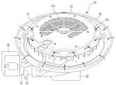
도2는 본 발명에 의한 식기세척기의 본체내부를 도시한 사시도이다.Figure 2 is a perspective view showing the inside of the main body of the dishwasher according to the present invention.
도3은 본 발명에 의한 섬프의 분해사시도이다.3 is an exploded perspective view of a sump according to the present invention.
도4는 본 발명에 의한 섬프하우징과 펌프모터의 분해사시도이다.Figure 4 is an exploded perspective view of the sump housing and the pump motor according to the present invention.
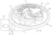
도5와 도9는 본 발명에 의한 섬프하우징과 펌프모터의 결합사시도이다.5 and 9 are combined perspective views of the sump housing and the pump motor according to the present invention.
도6은 본 발명에 의한 섬프의 상면을 나타낸 사시도이다.6 is a perspective view showing a top surface of a sump according to the present invention.
도7은 본 발명에 의한 섬프하우징의 상면을 나타낸 평면도이다.7 is a plan view showing the upper surface of the sump housing according to the present invention.
도8은 본 발명에 의한 섬프하우징과 임펠러케이싱의 결합사시도이다.8 is a perspective view of the sump housing and the impeller casing according to the present invention.
*도면의 주요부분에 대한 부호 설명*Description of the Related Art [0002]
13: 섬프16: 섬프하우징13: sump 16: sump housing
21: 세척임펠러24: 임펠러케이싱21: washing impeller 24: impeller casing
24c: 메인유로24d: 서브유로24c: Main Euro 24d: Sub Euro
24e: 오물챔버25: 유로제어밸브24e: dirt chamber 25: flow path control valve
27: 임펠러케이싱커버 27a: 안내유로27:
30: 펌프모터160: 배수유로30: pump motor 160: drainage flow path
300: 펌프모터수용부300: pump motor accommodating part
본 발명은 식기세척기에 관한 것으로서, 상세하게는 세척조의 공간을 확대하여 공간활용도를 높일 수 있는 식기세척기를 마련하는데 그 목적이 있다.The present invention relates to a dishwasher, and more particularly, to provide a dishwasher capable of increasing a space utilization by expanding a space of a washing tank.
식기세척기는 냉수 또는 온수를 이용하여 식기를 자동적으로 세척하는 장치로서, 종래의 식기세척기를 보면 대한민국공개특허공보 2005-54700호에 개시된바와 같이, 본체와, 본체 내부에 형성된 세척조와, 세척조 내부에 설치되는 식기바구니 및 세척조의 상단, 중단, 하단에 설치되어 세척수를 분사하는 메인노즐, 서브노즐을 포함한다.The dishwasher is a device for automatically washing dishes using cold water or hot water. As described in Korean Patent Laid-Open Publication No. 2005-54700, a dishwasher includes a main body, a washing tank formed inside the main body, and a washing tank inside the washing tank. Includes a main nozzle and a sub-nozzle installed at the top, middle, and bottom of the dish basket and the washing tank to be installed to spray the washing water.
그리고, 세척조의 하면에는 세척수를 수용하고, 각 노즐로 세척수를 펌핑하는 섬프가 구비되는데, 이러한 섬프의 구성을 보면 그 외관을 형성하는 섬프하우징과,섬프하우징 내부에 설치되는 히터와, 섬프하우징 내부에 수용되며 세척수를 펌핑하는 세척임펠러와, 세척임펠러로부터 펌핑되는 세척수를 각 노즐로 안내하는 유로와, 유로에 설치되어 세척수의 이동을 제어하는 유로제어밸브를 포함하고 있으며, 섬프하우징에 외부에 설치되어 세척임펠러를 구동시키는 펌프모터가 마련되어 있다.In addition, the lower surface of the washing tank is provided with a sump for accommodating the washing water and pumping the washing water with each nozzle. It includes a washing impeller accommodated in and pumping the wash water, a flow path for guiding the washing water pumped from the washing impeller to each nozzle, and a flow path control valve installed in the flow path to control the movement of the washing water, and installed outside the sump housing. And a pump motor for driving the washing impeller is provided.
그런데, 종래의 식기세척기는 섬프하우징의 내부에 히터가 마련되어서 섬프하우징의 높이가 커질 수 밖에 없었고, 상기 섬프하우징 하부에 펌프모터가 마련됨으로써 섬프와 펌프모터의 결합체의 높이가 증가되었다.However, in the conventional dishwasher, a heater is provided inside the sump housing to increase the height of the sump housing, and the height of the combination of the sump and the pump motor is increased by providing a pump motor under the sump housing.
따라서, 식기세척기 본체의 높이 중 섬프와 펌프모터의 결합체가 차지하는 비중이 높아져서 상대적으로 세척조의 공간이 줄어들 수 밖에 없다는 문제가 있었다.Therefore, the proportion of the sump and the combination of the pump motor of the height of the dishwasher main body has been increased, there was a problem that the space of the washing tank is relatively reduced.
본 발명은 이러한 문제점을 해결하기 위한 것으로서, 섬프와 펌프모터의 결합체의 높이를 감소시키는 동시에 세척조의 공간을 확대하여 공간활용도를 제고하는데 그 목적이 있다.The present invention is to solve this problem, the purpose of reducing the height of the sump and the combination of the pump motor and at the same time to expand the space of the washing tank to improve the space utilization.
이러한 목적을 달성하기 위한 본 발명은, 세척조와; 상기 세척조에 설치되는 섬프와; 상기 섬프의 외관을 구성하는 섬프하우징과; 상기 섬프하우징의 세척수를 펌핑하는 세척임펠러와; 상기 섬프하우징의 내부 주변부에 마련되는 배수유로와; 상기 배수유로에 둘러싸이며 상기 세척임펠러를 구동하는 펌프모터와; 상기 펌프모터가 수용되며 상기 배수유로보다 상부로 융기되는 펌프모터수용부를 포함하는 것을 특징으로 하는 식기세척기를 제공하고 있다.The present invention for achieving this object, the washing tank; A sump installed in the washing tank; A sump housing constituting an appearance of the sump; A washing impeller for pumping the washing water of the sump housing; A drain passage provided at an inner periphery of the sump housing; A pump motor surrounded by the drainage passage and driving the washing impeller; The pump motor is accommodated and provides a dishwasher, characterized in that it comprises a pump motor accommodating portion which is raised above the drain passage.
또한, 상기 펌프모터 수용부는 상기 섬프하우징의 하면에 형성되며, 상기 펌프모터가 삽입되어 결합되도록 그 하방이 개방되어 있는 것을 특징으로 한다.In addition, the pump motor accommodating portion is formed on the lower surface of the sump housing, characterized in that the pump motor is inserted in the lower opening so that the coupling.
또한 상기 펌프모터의 주변부에는 스크류가 관통할 수 있는 관통공이 형성되며, 상기 펌프모터 수용부에는 상기 관통공을 관통한 스크류가 결합되는 스크류결합부가 돌출되어 마련되는 것을 특징으로 한다.In addition, a through hole through which a screw may pass is formed in the periphery of the pump motor, and the pump motor accommodating part may include a screw coupling part protruding from the screw through the through hole.
또한, 상기 히터는 상기 섬프를 둘러싸고 있는 형상으로 배치되는 것을 특징 으로 한다.In addition, the heater is characterized in that it is arranged in a shape surrounding the sump.
또한, 상기 세척조의 하부에는 상기 히터가 상기 섬프를 둘러싸면서 배치될 수 있도록 하는 히터설치홈이 마련되며, 상기 히터설치홈에는 상기 히터를 덮는 히터커버가 마련되고, 상기 히터커버에는 세척수가 상기 히터와 접촉할 수 있도록 다수의 중공부가 형성되는 것을 특징으로 한다.In addition, a heater installation groove is provided in the lower portion of the washing tank so that the heater can be disposed surrounding the sump, the heater installation groove is provided with a heater cover for covering the heater, the heater cover the washing water is the heater It characterized in that a plurality of hollow portion is formed to be in contact with.
또한, 상기 세척조에는 식기세척시 항상 세척수를 분사하는 메인노즐과, 선택적으로 세척수를 분사하는 서브노즐과; 상기 섬프내에 마련되고 상기 메인노즐과 연통되는 메인유로와, 상기 메인유로와 별도로 마련되고 상기 서브노즐과 연통되는 서브유로와; 상기 서브유로에 마련되어 상기 서브유로로 흐르는 세척수의 흐름을 선택적으로 단속하는 유로제어밸브를 더 포함하는 것을 특징으로 한다.In addition, the washing tank includes a main nozzle for always spraying the washing water during dish washing, and a sub-nozzle for selectively spraying the washing water; A main flow passage provided in the sump and communicating with the main nozzle, and a sub flow passage provided separately from the main flow passage and communicating with the sub nozzle; It is characterized in that it further comprises a flow path control valve provided in the sub-channel to selectively control the flow of the washing water flowing into the sub-channel.
또한, 상기 임펠러케이싱의 상부에는 상기 임펠러케이싱을 덮는 임펠러케이싱 커버가 마련되며, 상기 임펠러케이싱커버에는 상기 서브유로와 연통되어 세척수를 상기 하부노즐로 안내하는 안내유로가 마련된 것을 특징으로 한다.In addition, an impeller casing cover covering the impeller casing is provided at an upper portion of the impeller casing, and the impeller casing cover is provided with a guide flow passage communicating with the sub-flow passage to guide the washing water to the lower nozzle.
또한, 상기 임펠러케이싱에는 상기 메인유로와 연통되어 세척수에 포함된 오물을 수집하는 오물챔버가 마련되는 것을 특징으로 한다.In addition, the impeller casing is characterized in that the waste chamber is in communication with the main flow passage for collecting the dirt contained in the wash water.
또한, 상기 오물챔버는 그 상부가 개방되며, 상기 오물챔버의 상부에는 세척수와 오물을 분리하여 세척수만 오버플로우시키는 메쉬필터가 마련되는 것을 특징으로 한다.In addition, the top of the dirt chamber is open, characterized in that the upper part of the dirt chamber is provided with a mesh filter for separating the wash water and dirt to overflow only the wash water.
이하에서는 첨부된 도면을 참조하여 본 발명의 바람직한 실시예에 대하여 알아보기로 하겠다.Hereinafter, exemplary embodiments of the present invention will be described with reference to the accompanying drawings.
도1에서 도시한 바와 같이, 본 발명에 의한 식기세척기는 그 외관을 형성하는 본체(1)와, 상기 본체의 내부에 마련되는 세척조(2)와, 상기 세척조(2)의 측벽에 설치되는 랙(5)이 배치되는데, 상기 랙(5)은 상부랙(5a)와 하부랙(5b)이 마련되며 상기 랙(5)에는 접시 등과 같은 식기를 안치시킬 수 있는 상부식기바구니(7a)와 하부식기바구니(7b)가 마련된다.As shown in FIG. 1, the dishwasher according to the present invention includes a
한편, 상기 세척조(2)의 상단과 중단과 하단에는 세척수를 각각 분사하는 메인노즐(10a,10b), 그리고 서브노즐(10c)이 구비되는데, 이러한 노즐들의 분사방향은 상기 식기바구니(7a,7b)를 향하도록 되어 있고, 상기 노즐은 분사되는 세척수의 분사압으로 인하여 회전하며, 상기 노즐(10a,10b,10c)로부터 분사되는 세척수는 상기 식기바구니(7a,7b)에 있는 식기와 충돌하여 강한 세척력을 발휘한다.On the other hand, the top, middle and bottom of the washing tank (2) is provided with a main nozzle (10a, 10b), and a sub-nozzle (10c) for spraying the washing water, respectively, the spraying direction of these
상기 세척조(2)의 하면에는 세척수를 수용하고 펌핑하여 상기 노즐들에 공급하는 섬프(13)가 설치된다.The lower surface of the washing tank (2) is provided with a sump (13) for receiving and pumping the washing water to the nozzles.
상기 세척조(2)의 후면에는 상기 메인노즐(10a,10b)로 세척수를 공급하는 이송관(11)이 배치되는데, 상기 이송관(11)의 하단은 상기 섬프(13)와 연결됨으로써 상기 섬프(13)의 강한 펌핑압력으로 인하여 유동하는 세척수가 상기 이송관(11)의 안내를 받아서 상기 메인노즐(10a,10b)로 이동하는 것이다.The rear side of the washing tank (2) is provided with a
또한, 상기 섬프(13)의 상부의 중앙부에는 상기 서브노즐(10c)이 바로 연결되어 있어서, 세척수의 일부는 상기 서브노즐(10c)을 통과하여 분사되어 상기 서브노즐(10c)과 근접하여 있는 하부식기바구니(7b)에 담긴 식기들을 세척하게 된다.In addition, the
본 발명에서는 식기가 상대적으로 소량인 경우에는 식기를 상부식기바구니(7 a)에만 넣고 상기 메인노즐(10a,10b)에서만 세척수를 분사하도록 하며 서브노즐(10c)에서는 세척수가 분사되지 않는 것이 바람직하나, 그 반대의 경우도 당업자 입장에서는 실시할 수 있는 범주에 속한다고 볼 수 있다.In the present invention, when the dishware is relatively small, the dishwasher is placed only in the
한편, 상기 섬프(13)를 보면 그 외관을 형성하는 섬프하우징(16)과, 상기 섬프하우징(16)을 덮는 섬프커버(19), 그리고 상기 섬프하우징(16) 내에 수용되어 있는 세척임펠러(21)와, 상기 세척임펠러(21)가 설치되는 임펠러케이싱(24) 및, 상기 임펠러케이싱(24) 위에 얹혀지는 임펠러케이싱커버(27)등으로 구성되어 있는 것을 알 수 있다.On the other hand, when the
또한, 상기 섬프하우징(16)의 하부에는 상기 세척임펠러(21)를 구동시키는 펌프모터(30)가 설치되는데, 상기 섬프하우징(16)의 하부에는 상기 펌프모터(30)가 수용되어 결합될 수 있도록 하는 펌프모터수용부(300)가 마련된다.In addition, a
그리고, 상기 펌프모터(30)는 상기 섬프하우징(16)에 단단히 결합되도록 스크류를 이용하여 체결되는 것이 바람직하나, 스크류 이외에도 상호결합을 도모할 수 있는 체결부재도 생각할 수 있다.In addition, the
따라서, 상기 섬프(13)부분을 보면 상기 섬프(13)의 하부와 상기 펌프모터(30)의 상부가 일정범위만큼 겹쳐지게 된다.Therefore, when looking at the
그리하여, 그 겹쳐지는 부분만큼 상기 섬프(13)와 상기 펌프모터(30)가 결합된 상태에서의 높이가 줄어들게 되므로, 이러한 높이의 감소는 결국 상기 세척조(2)의 상하높이를 상대적으로 증대시킬 수 있는 결과를 불러온다.Thus, since the height in the state where the
한편, 상기 섬프하우징(16)의 측면에는 배수펌프(33)가 마련되어서 상기 섬 프내(13)에 있는 세척수와 오물을 식기세척기 외부로 배출하는 역할을 한다.On the other hand, the side of the
상기 섬프(13)의 주위에는 세척수를 가열하는 히터(36)가 마련되는데, 상기 세척조(2)의 하부에는 상기 섬프(13)의 주위를 따라 형성되는 히터설치홈(39)이 형성되어, 상기 히터(36)가 상기 히터설치홈(39)에 수용되는 것이다.A
또한, 상기 히터설치홈(39)에 히터(36)가 수용된 후에는 상기 히터(36)를 덮을 수 있도록 히터커버(42)가 마련되어 상기 히터(36)가 외부로 노출되는 것을 방지한다.In addition, after the
도2에서 도시한 바와 같이, 상기 세척조(2)의 내부를 보면 일측면에 세척수가 유입되는 유입장치(3)가 마련되고, 상기 유입장치(3)를 통하여 들어온 세척수는 상기 세척조(2)의 바닥면으로 낙하하여 흘러서 상기 섬프(13)로 유입되도록 되어 있다.As shown in FIG. 2, when looking at the inside of the
상기 섬프(13)의 중앙부에는 상기 서브노즐(10c)이 회전가능하게 결합되어 있고, 상기 섬프(13)의 후단부에는 상기 이송관(11)이 연결되어 상기 메인노즐(미도시)로 세척수를 안내한다.The
상기 섬프(13)의 상면에는 섬프커버(19)가 설치되며, 상기 섬프커버(19)의 주변부에는 유입구(19a)가 일정간격 이격되게 마련됨으로써 상기 유입구(19a)의 안내를 받아 세척수가 상기 섬프(13)내부로 유입되는 것이다.A
한편, 상기 섬프커버(19)의 상면에는 필터커버(20)가 마련되고, 상기 필터커버(20)에는 메쉬필터(20a)가 설치되어 후술할 오물챔버(미도시)에 포집된 오물이 상기 오물챔버 밖으로 넘쳐흐리지 않도록 하는 한편, 세척수만 오물챔버 밖으로 흘 러나가도록 한다.Meanwhile, a
그리고, 상기 섬프(13)의 주위에는 상기 히터(36)가 원환형태로 설치되며, 상기 히터(13)의 위에는 히터커버(42)가 마련되는데, 상기 히터커버(42)의 표면에는 중공부(42a)가 마련되어 상기 중공부(42a)를 통과하여 세척수가 상기 히터(39)로 흘러들어가 가열된 후 상기 섬프(13)로 유입되는 것이다.In addition, the
도3은 상기 섬프(13)의 구조를 도시한 것으로서, 상기 섬프하우징(16)의 일측면에는 배수펌프(33)가 설치되는 펌프설치부(50)가 마련되며, 상기 펌프설치부(50)의 일측면에는 세척수와 오물의 배출을 안내하는 배수관(51)이 마련된다.3 shows a structure of the
또한, 상기 섬프하우징(16)에는 상기 임펠러수용부(300)의 하면에 상기 펌프모터(30)가 설치되며, 상기 펌프모터수용부(300)의 주변부에는 상기 펌프모터수용부(300)를 둘러싸는 배수유로(160)가 마련되고, 상기 배수유로(160)는 상기 펌프모터수용부(300)를 둘러싸는 제1,2,3배수유로(161,162,163)으로 구성되는데, 이 중 상기 제3배수유로(163)는 상기 제1,2배수유로(161,162)를 연통시키면서 세척수 및 오물을 상기 배수펌프(33)쪽으로 안내하는 역할을 한다.In addition, the
이때, 상기 펌프모터수용부(300)의 상면은 상기 배수유로(160)의 바닥면보다 상대적으로 상부에 위치하여 있다는 것을 알 수 있다.In this case, it can be seen that the upper surface of the pump
그리하여, 상기 배수유로(160)를 통하여 세척수 및 오물을 배출한다는 기능을 해하지 않으면서도 상기 펌프모터수용부(300)에 상기 펌프모터(30)가 수용되어서 상기 섬프(13)와 상기 펌프모터(30)의 결합체 높이를 상당부분 감소시킬 수 있는 것이다.Thus, the
한편, 상기 펌프모터(30)의 회전축(30a)이 상기 펌프모터수용부(300)를 관통하여 돌출되어 있고, 상기 펌프모터수용부(300)에는 상기 회전축(30a)을 둘러싸는 실링부재(53)가 마련됨으로써 세척수가 상기 펌프모터(30)쪽으로 누수되지 않도록 한다.On the other hand, the
한편, 상기 섬프하우징(16)의 상면에는 상기 임펠러케이싱(24)이 마련되는데, 상기 임펠러케이싱(24)의 중앙부에는 상기 섬프하우징(16)과 연통되는 연통공(24a)이 형성되며, 상기 연통공(24a)의 주위에는 상기 세척임펠러(21)가 설치되는 임펠러수용부(24b)가 마련된다.On the other hand, the
상기 세척임펠러(21)는 상기 펌프모터(30)의 회전축(30a)과 결합하여 회전하면서 상기 섬프하우징(16)으로 유입된 세척수를 상부로 끌어올리는 역할을 한다.The
상기 임펠러케이싱(24)에는 상기 임펠러수용부(24b)로부터 분기되는 메인유로(24c)와 서브유로(24d)가 마련되는데, 상기 메인유로(24c)는 상기 메인노즐(도1참고, 10a,10b)로 움직이는 세척수를 안내하고, 상기 서브유로(24d)는 상기 서브노즐(도1참고, 10c)로 움직이는 세척수를 안내하는 역할을 한다.The
여기서 상기 메인유로(24c)에는 세척수의 흐름을 단속하는 다른 장치가 설치되지 않아서 식기세척기가 세척을 실시하면 기본적으로 상기 메인유로(24c)를 통과하게 되므로, 상기 메인유로(24c)는 상기 섬프에서 세척수가 흐르는 기본유로가 된다.In this case, since no other device is provided in the
따라서, 기본유로가 되기 때문에 그 세척수의 분사압이 저하되지 않도록 상기 메인유로(24c)의 형상은 상기 임펠러수용부(24a)로부터 뻗어나가는 부드러운 곡 선형상으로 이루어지는 것이 바람직하다.Therefore, it is preferable that the shape of the
즉, 상기 메인유로(24c)가 꺾이게 된다면 세척수가 꺽이는 부분에서 충돌함으로써 그 운동에너지의 손실이 있게되므로 이러한 손실을 최소화 하도록 곡선으로 형성하는 것이다.In other words, if the
또한, 상기 서브유로(24d)에는 유로제어밸브(25)가 회동가능하게 설치되는데, 이는 서브유로(24d)로 흘러들어가는 세척수의 흐름을 단속하는 역할을 하는 것으로서, 세척해야할 식기의 양이 적은 경우에는 상기 유로제어밸브(25)가 상기 서브유로(24d)를 차단함으로써 세척수가 메인유로(24c)로만 유동하게 하는 기능을 한다.In addition, the flow path control
그럼으로써 메인유로(24c)의 안내를 받아서 이동하는 세척수는 상기 메인노즐(도1참고, 10a, 10b)에서 분사되어 식기를 세척하게 되는 것이고, 이는 세척대상이 되는 식기의 양이 적은 경우 세척수의 소요량을 감소시켜서 세척수를 절약하기 위한 것이다.As a result, the washing water moving under the guidance of the
한편, 상기 메인유로(24c)의 옆에는 오물챔버(24e)가 형성되는데, 이는 메인유로(24c)로 흘러들어간 오물이 세척수와 함께 포집되도록 마련되는 것이며, 상기 오물챔버(24e)의 입구근처에는 상기 배수펌프(33)와 연결되는 배수이송관(26)이 설치되어, 상기 배수펌프(33)가 작동하면 오물챔버(24e)에 포집된 오물들이 상기 배수펌프(33)의 작동에 의해 배수이송관(26)을 따라서 상기 배수관(51)쪽으로 배출되는 것이다.On the other hand, a
이와 같이, 상기 메인유로(24c)와 상기 서브유로(24d)와 상기 오물챔버(24e) 는 하나의 임펠러케이싱(24)에 형성되는 것을 알 수 있다.In this way, it can be seen that the
한편, 임펠러케이싱(24) 위에는 상기 임펠러케이싱커버(27)가 마련되는데, 상기 임펠러케이싱커버(27)에는 상기 서브유로(24d)와 연통되는 안내유로(27a)가 마련되며, 상기 안내유로(27a)는 상기 임펠러케이싱커버(27)의 주변부에서 곡선을 그리면서 상기 임펠러케이싱커버(27)의 중앙부까지 연장된다.On the other hand, the
따라서, 상기 유로제어밸브(25)가 상기 서브유로(24d)를 개방하면 상기 세척임펠러(21)에 의하여 펌핑되는 세척수가 상기 유로제어밸브(25)를 통과하여 상기 서브유로(24d)를 따라 움직이다가, 상기 서브유로(24d)와 연통되는 상기 안내유로(27a)를 지나 상기 서브노즐(도1참고, 10c)까지 움직인 후에 분사되는 것이다.Therefore, when the
한편, 상기 임펠러케이싱커버(27)의 상부에는 섬프커버(19)가 마련되는데, 상기 섬프커버(19)의 중앙부에는 상기 서브노즐(도1참고, 10c)의 하부가 결합하는 결합공(19c)가 마련되고, 상기 섬프커버(19)의 주변부에는 세척수가 유입될 수 있는 유입구(19a)가 일정간격 이격되어 복수개가 형성되어 있다.Meanwhile, a
그리고, 상기 임펠러케이싱커버(27)에는 상기 이송관(도2참고, 11)이 관통하여 상기 메인유로(24c)까지 연결될 수 있도록 하는 연결공(19b)이 마련된다.In addition, the
그리고, 상기 섬프커버(19)의 상부에는 필터커버(20)가 마련되는데, 상기 필터커버(20)에는 상기 메쉬필터(20a)가 설치되어 상기 오물챔버(24e)의 상면을 덮게 됨으로써 상기 오물챔버(24e)에 수용되는 오물이 세척수를 따라서 상기 메쉬필터(20a) 바깥으로 나오지 못하게 하는 역할을 하는 것이다.A
즉, 상기 메쉬필터(20a)에 의하여 상기 오물챔버(24e)에 세척수와 오물이 같 이 들어온 경우, 세척수는 상기 메쉬필터(20a)를 통과하지만, 오물은 상기 메쉬필터(20a)에 의해 걸려서 오물챔버(24e)의 내에 잔존하게 된다.That is, when the wash water and the dirt enter the
그리하여, 상기 오물과 분리된 세척수는 다시 상기 유입구(19a)로 이동하여 상기 섬프(13) 내부로 유입되고, 상술한 과정을 거치면서 계속 순환하는 것이다.Thus, the wash water separated from the dirt is moved to the inlet (19a) again and introduced into the sump (13), and continues to circulate while going through the above-described process.
한편, 상기 섬프(13) 주위에는 상기 히터(도2참고,36)와 상기 히터커버(42)가 마련되어 상기 섬프(13) 주위를 둘러싸고 있는 것을 알 수 있다.Meanwhile, it can be seen that the heater (see FIG. 2 and 36) and the
도4와 도시한 바와 같이, 상기 섬프하우징(16)의 중심에는 상기 펌프모터수용부(300)가 마련되고, 상기 펌프모터수용부(300)에는 스크류결합부(16a)가 하부로 돌출되도록 마련된다.As shown in FIG. 4, the pump
그리고, 상기 펌프모터수용부(300)의 주변에는 상기 1,2,3배수유로(161,162,163)들이 형성되며, 상기 배수유로(160)는 상기 펌프모터수용부(300)보다 하부로 돌출되어 있다.In addition, the first and
한편, 상기 펌프모터(30)의 주변에는 상기 스크류결합부(16a)의 위치에 대응되는 스크류관통부(30a)가 마련된다.On the other hand, around the
따라서, 도5에서 도시한 바와 같이 스크류(31)가 상기 스크류관통부(도4참고, 30a)를 통과하여 상기 스크류결합부(16a)에 결합되면, 상기 펌프모터(30)는 상기 펌프모터수용부(300)에 설치된 상태에서 상기 배수유로(161,162,163)들에 의하여 둘러싸게 된다.Accordingly, as shown in FIG. 5, when the
한편, 상기 섬프하우징(16)의 일측면에는 상기 배수펌프설치부(51)가 마련되어 그 곳에 상기 배수펌프(33)가 설치되고, 한편에는 섬프하우징(16)에 수용된 세 척수의 오염도와 세척수의 수위를 센싱하는 센서부(170)가 마련되는데, 상기 센서부(60)의 감지정보에 따라서 상기 배수펌프(33)가 섬프하우징(16) 내의 세척수와 오물을 외부로 배출하는 역할을 한다.On the other hand, one side of the
그리고, 상기 섬프하우징(16) 하부에는 상기 유로제어밸브(미도시)를 구동하는 밸브구동모터(62)가 설치됨으로써, 상기 유로제어밸브(미도시)가 상기 서브유로(미도시)를 개방 또는 폐쇄하도록 하는 것이다.In addition, a
이하에서는 첨부된 도면을 참조하여 본 발명의 동작에 대하여 알아보기로 하겠다.Hereinafter, an operation of the present invention will be described with reference to the accompanying drawings.
도6에서 개시된 바와 같이, 상기 히터(36)와 접촉하는 세척수는 가열이 되어 상기 섬프(13)내부로 유입되며, 도7에서 개시된 바와 같이, 상기 섬프하우징(16)에 수용된 세척수는 상기 회전축에 설치된 세척임펠러(21)가 회전함에 따라서 상기 임펠러케이싱(24)으로 끌어올려지게 된다.As disclosed in FIG. 6, the wash water contacting the
이렇게 펌핑된 세척수는 상기 세척임펠러의 회전력에 의하여 상기 임펠러수용부(24b)를 벗어나 상기 메인유로(24c, 화살표 A방향)와 상기 서브유로(24d,화살표B방향)로 동시에 이동하거나 혹은 상기 서브유로(24d)가 상기 유로제어밸브(25)에 의하여 폐쇄된 경우에는 상기 메인유로(24c)로만 이동한다.The pumped washing water moves out of the
상기 화살표A와 같이 상기 메인유로(24c)의 안내를 받아서 이동하는 세척수는 상기 세척임펠러(21)의 강한 압력으로 인하여 이송관(도2참고,11)을 타고 위로 상승하여 상기 메인노즐(도1참고, 10a, 10b)로 이동한다.The washing water moving under the guidance of the
즉, 세척대상인 식기가 소량이어서 메인노즐(도1참고, 10a,10b)만 작동시킬 경우에는 상기 유로제어밸브(25)는 상기 서브유로(24d)를 폐쇄하게 되고, 이에 따라 세척수는 메인유로(24c)로만 이동하게 되어, 상기 이송관(11)을 따라서 상기 메인노즐(10a,10b)로 이동한 뒤에 분사되는 것이다.That is, when a small amount of dishes to be cleaned, and only the main nozzle (see Fig. 1, 10a, 10b) is operated, the flow path control
그리고, 식기의 양이 많아서 서브노즐(도1참고, 10c)까지 작동시키는 경우에는 상기 유로제어밸브(25)가 상기 서브유로(24d)를 개방하고, 이에 세척수는 화살표B방향으로 이동하며 상기 서브노즐(10c)방향으로 이동하여 분사되는 것이다.In addition, when the amount of the dishes is large and the sub-nozzle (see FIG. 1, 10c) is operated, the flow path control
한편 상기 메인유로(24c)에는 상기 오물챔버(24e)가 연결되어서 일부 세척수와 혼합된 오물이 이동하여(화살표C방향) 포집된다.On the other hand, the
상기 오물챔버(24e)의 입구부에 근접한 곳에는 상기 배수펌프(33)와 연결되는 배수연결관(26)이 마련되어, 상기 배수펌프(33) 작동시에는 상기 오물챔버(24e)에 포집된 오물들이 상기 배수펌프(33)의 동작으로 인하여 외부로 배출되는 것이다(화살표D방향).A
제8도에서 도시한 바와 같이, 상기 임펠러케이싱(24)의 상부에 있는 상기 임펠러케이싱커버(27)에는 상기 안내유로(27a)가 상기 서브유로(도7참고, 24d)와 연통되도록 형성된다.As shown in FIG. 8, the
이때, 상기 서브유로(24d)가 상기 유로제어밸브(도7참고, 25)에 의하여 개방된 상태에서 상기 세척임펠러(도7참고, 21)가 작동을 하게 되면, 상술하였다시피 상기 서브유로(24d)로도 세척수가 이동하고, 상기 서브유로(24d)로 이동한 세척수는 상기 안내유로(27a)의 안내를 받아서 상기 임펠러케이싱커버(27) 중앙부로 이동한 다음에 화살표 A의 방향과 같이 상기 서브노즐(도1참고,10c)로 이동하여 분사되 는 것이다.At this time, when the cleaning impeller (see Fig. 7, 21) is operated in the state in which the
한편, 여기서 화살표 B는 상기 메인노즐(도1,10a,10b참고)로 이동하는 세척수의 이동방향을 나타낸 것이다.On the other hand, the arrow B shows the movement direction of the washing water moving to the main nozzle (see Fig. 1, 10a, 10b).
도9에서 도시한 바와 같이, 상기 메인유로(도7참고, 24c)를 따라 이동하다가 상기 오물챔버(도7참고, 24e)로 들어간 세척수 및 오물은 그 뒤에 따라오는 세척수 등의 압력에 의하여 상기 메쉬필터(20a)쪽으로 배출되려고 하나 상기 메쉬필터(20a)에 의하여 상기 오물은 통과하지 못하여 상기 오물챔버(도7참조, 24e)에 남아 있고, 세척수만 화살표 E 방향으로 상기 메쉬필터(20a)를 통과하여 상기 섬프(13) 외부로 배출된다.As shown in FIG. 9, the washing water and the dirt moving along the main flow passage (refer to FIG. 7 and 24c) and entering the dirt chamber (refer to FIG. 7 and 24e) are connected to the mesh by the pressure of the washing water following. Although it is about to be discharged toward the
이후, 배출된 세척수는 다시 상기 섬프(13) 내부로 들어가며 상술한 바와 같이 섬프(13)내부를 움직이며 세척작용을 하는 것이다.Thereafter, the discharged washing water enters into the
이러한 본 발명에 의하여 펌프모터가 섬프하우징에 수용되면서 결합되므로, 그 수용된 부분만큼 섬프 및 펌프모터 설치높이가 절약되는 효과가 있으며, 이러한 효과로 인하여 본체내부에서 세척조가 차지하는 공간이 넓어지게 된다는 장점이 있다.Since the pump motor is coupled to the sump housing while being accommodated by the present invention, the sump and the pump motor installation height are saved as much as the accommodated portion. Due to this effect, the space occupied by the washing tank in the main body becomes wider. have.
Claims (9)
Translated fromKoreanPriority Applications (4)
| Application Number | Priority Date | Filing Date | Title |
|---|---|---|---|
| KR1020060065596AKR101266869B1 (en) | 2006-07-12 | 2006-07-12 | A tableware washing machine |
| US11/806,520US7993472B2 (en) | 2006-07-12 | 2007-05-31 | Dish washing machine having pump motor and pump motor receiving part |
| CNB2007101100609ACN100551322C (en) | 2006-07-12 | 2007-06-19 | dishwasher |
| US13/067,910US20110265833A1 (en) | 2006-07-12 | 2011-07-06 | Dish washing machine having pump motor and pump motor receiving part |
Applications Claiming Priority (1)
| Application Number | Priority Date | Filing Date | Title |
|---|---|---|---|
| KR1020060065596AKR101266869B1 (en) | 2006-07-12 | 2006-07-12 | A tableware washing machine |
Publications (2)
| Publication Number | Publication Date |
|---|---|
| KR20080006410A KR20080006410A (en) | 2008-01-16 |
| KR101266869B1true KR101266869B1 (en) | 2013-05-23 |
Family
ID=38948025
Family Applications (1)
| Application Number | Title | Priority Date | Filing Date |
|---|---|---|---|
| KR1020060065596AActiveKR101266869B1 (en) | 2006-07-12 | 2006-07-12 | A tableware washing machine |
Country Status (3)
| Country | Link |
|---|---|
| US (2) | US7993472B2 (en) |
| KR (1) | KR101266869B1 (en) |
| CN (1) | CN100551322C (en) |
Families Citing this family (10)
| Publication number | Priority date | Publication date | Assignee | Title |
|---|---|---|---|---|
| US8424546B2 (en) | 2008-07-15 | 2013-04-23 | Electrolux Home Products, Inc. | Sump assembly for a dishwasher, and associated method |
| CN102497800B (en)* | 2009-08-10 | 2015-03-25 | 伊莱克斯家用产品公司 | Fluid circulation arrangement for providing an intensified wash effect in a dishwasher and an associated method |
| CN104235060A (en)* | 2013-06-05 | 2014-12-24 | 宁波方太厨具有限公司 | Impeller of open type water pump |
| EP2818090B1 (en)* | 2013-06-27 | 2016-08-17 | Samsung Electronics Co., Ltd | Dish washing machine and sump assembly thereof |
| KR102379020B1 (en) | 2013-12-31 | 2022-03-28 | 삼성전자주식회사 | Dish washing machine and method of controlling the same |
| KR101617298B1 (en)* | 2014-08-22 | 2016-05-02 | 엘지전자 주식회사 | Dishwasher |
| US11000177B2 (en)* | 2015-02-13 | 2021-05-11 | Fisher & Paykel Appliances Limited | Wash system for washing appliance |
| US9888827B2 (en)* | 2015-04-08 | 2018-02-13 | Haier Us Appliance Solutions, Inc. | Dishwasher appliance and a method for forming a unitary tub |
| KR102679834B1 (en)* | 2017-01-26 | 2024-07-01 | 엘지전자 주식회사 | Dishwasher |
| KR102454768B1 (en) | 2017-08-31 | 2022-10-13 | 엘지전자 주식회사 | Pump and Dishwasher comprising the Same |
Citations (3)
| Publication number | Priority date | Publication date | Assignee | Title |
|---|---|---|---|---|
| KR100239936B1 (en)* | 1991-12-20 | 2000-03-02 | 윌리엄 린드세이 길랜더즈 | Dishwasher |
| KR100488033B1 (en) | 2003-07-31 | 2005-05-06 | 엘지전자 주식회사 | Control appatatus for washing flow of dishwasher |
| US20060054200A1 (en) | 2004-09-16 | 2006-03-16 | Lg Electronics Inc. | Dishwasher |
Family Cites Families (8)
| Publication number | Priority date | Publication date | Assignee | Title |
|---|---|---|---|---|
| DE3716954A1 (en)* | 1987-05-20 | 1988-12-01 | Bosch Siemens Hausgeraete | ARRANGEMENT OF ELECTRICAL HEATING IN A HOUSEHOLD DISHWASHER |
| SE500246C2 (en)* | 1990-04-26 | 1994-05-24 | Electrolux Ab | Arrangement by a dishwasher |
| US6622754B1 (en)* | 2001-12-19 | 2003-09-23 | Whirlpool Corporation | Load-based dishwashing cycle |
| KR100556780B1 (en) | 2003-12-05 | 2006-03-10 | 엘지전자 주식회사 | Dishwasher with contamination detection sensor |
| KR20050062145A (en)* | 2003-12-19 | 2005-06-23 | 엘지전자 주식회사 | Apparatus gathering water in the dishwasher |
| KR20060024597A (en) | 2004-09-14 | 2006-03-17 | 엘지전자 주식회사 | Dishwasher Structure |
| KR100772222B1 (en)* | 2004-12-07 | 2007-11-01 | 엘지전자 주식회사 | Sump structure of dishwasher |
| KR101295952B1 (en)* | 2006-09-27 | 2013-08-13 | 엘지전자 주식회사 | Sump for dish washer |
- 2006
- 2006-07-12KRKR1020060065596Apatent/KR101266869B1/enactiveActive
- 2007
- 2007-05-31USUS11/806,520patent/US7993472B2/enactiveActive
- 2007-06-19CNCNB2007101100609Apatent/CN100551322C/ennot_activeExpired - Fee Related
- 2011
- 2011-07-06USUS13/067,910patent/US20110265833A1/ennot_activeAbandoned
Patent Citations (3)
| Publication number | Priority date | Publication date | Assignee | Title |
|---|---|---|---|---|
| KR100239936B1 (en)* | 1991-12-20 | 2000-03-02 | 윌리엄 린드세이 길랜더즈 | Dishwasher |
| KR100488033B1 (en) | 2003-07-31 | 2005-05-06 | 엘지전자 주식회사 | Control appatatus for washing flow of dishwasher |
| US20060054200A1 (en) | 2004-09-16 | 2006-03-16 | Lg Electronics Inc. | Dishwasher |
Also Published As
| Publication number | Publication date |
|---|---|
| CN101103891A (en) | 2008-01-16 |
| US20080011340A1 (en) | 2008-01-17 |
| US20110265833A1 (en) | 2011-11-03 |
| US7993472B2 (en) | 2011-08-09 |
| KR20080006410A (en) | 2008-01-16 |
| CN100551322C (en) | 2009-10-21 |
Similar Documents
| Publication | Publication Date | Title |
|---|---|---|
| KR101266869B1 (en) | A tableware washing machine | |
| KR101266868B1 (en) | A tableware washing machine | |
| KR101270538B1 (en) | A tableware washing machine | |
| KR101938710B1 (en) | Dish washer | |
| KR100606823B1 (en) | Dishwasher | |
| CN101164490B (en) | Dishwasher | |
| KR101292538B1 (en) | A dish washing machine | |
| KR101507803B1 (en) | Dish washer | |
| KR101268784B1 (en) | Dish washer | |
| KR100556779B1 (en) | dish washer | |
| KR101054154B1 (en) | Air brake in dishwasher | |
| KR20070105046A (en) | dish washer | |
| KR200397408Y1 (en) | Heater's combining structure of dish washer | |
| KR20100067571A (en) | Dish washing machine | |
| KR101308375B1 (en) | A tableware washing machine | |
| KR0176946B1 (en) | Discharge flow path structure of dishwasher | |
| KR101270539B1 (en) | A tableware washing machine | |
| KR101052780B1 (en) | dish washer | |
| KR20120022426A (en) | A dishwasher | |
| KR20060085782A (en) | Sump structure of dishwasher | |
| KR101054183B1 (en) | Air brake structure of dishwasher | |
| KR101052965B1 (en) | Leakage prevention structure of the dishwasher | |
| WO2006001603A1 (en) | A sump of dish washer | |
| KR20130035133A (en) | A dishwasher | |
| KR20060043892A (en) | Euro structure of dishwasher sump |
Legal Events
| Date | Code | Title | Description |
|---|---|---|---|
| PA0109 | Patent application | Patent event code:PA01091R01D Comment text:Patent Application Patent event date:20060712 | |
| PG1501 | Laying open of application | ||
| A201 | Request for examination | ||
| PA0201 | Request for examination | Patent event code:PA02012R01D Patent event date:20110511 Comment text:Request for Examination of Application Patent event code:PA02011R01I Patent event date:20060712 Comment text:Patent Application | |
| E902 | Notification of reason for refusal | ||
| PE0902 | Notice of grounds for rejection | Comment text:Notification of reason for refusal Patent event date:20121120 Patent event code:PE09021S01D | |
| E701 | Decision to grant or registration of patent right | ||
| PE0701 | Decision of registration | Patent event code:PE07011S01D Comment text:Decision to Grant Registration Patent event date:20130429 | |
| GRNT | Written decision to grant | ||
| PR0701 | Registration of establishment | Comment text:Registration of Establishment Patent event date:20130516 Patent event code:PR07011E01D | |
| PR1002 | Payment of registration fee | Payment date:20130520 End annual number:3 Start annual number:1 | |
| PG1601 | Publication of registration | ||
| FPAY | Annual fee payment | Payment date:20160428 Year of fee payment:4 | |
| PR1001 | Payment of annual fee | Payment date:20160428 Start annual number:4 End annual number:4 | |
| FPAY | Annual fee payment | Payment date:20170427 Year of fee payment:5 | |
| PR1001 | Payment of annual fee | Payment date:20170427 Start annual number:5 End annual number:5 | |
| FPAY | Annual fee payment | Payment date:20180427 Year of fee payment:6 | |
| PR1001 | Payment of annual fee | Payment date:20180427 Start annual number:6 End annual number:6 | |
| PR1001 | Payment of annual fee | Payment date:20200428 Start annual number:8 End annual number:8 | |
| PR1001 | Payment of annual fee | Payment date:20210429 Start annual number:9 End annual number:9 | |
| PR1001 | Payment of annual fee | Payment date:20220428 Start annual number:10 End annual number:10 | |
| PR1001 | Payment of annual fee | Payment date:20230427 Start annual number:11 End annual number:11 | |
| PR1001 | Payment of annual fee | Payment date:20240430 Start annual number:12 End annual number:12 | |
| PR1001 | Payment of annual fee | Payment date:20250429 Start annual number:13 End annual number:13 |