KR101265568B1 - Bio sensing device - Google Patents
Bio sensing deviceDownload PDFInfo
- Publication number
- KR101265568B1 KR101265568B1KR1020100066347AKR20100066347AKR101265568B1KR 101265568 B1KR101265568 B1KR 101265568B1KR 1020100066347 AKR1020100066347 AKR 1020100066347AKR 20100066347 AKR20100066347 AKR 20100066347AKR 101265568 B1KR101265568 B1KR 101265568B1
- Authority
- KR
- South Korea
- Prior art keywords
- layer
- reaction
- signal
- unit
- bio
- Prior art date
- Legal status (The legal status is an assumption and is not a legal conclusion. Google has not performed a legal analysis and makes no representation as to the accuracy of the status listed.)
- Expired - Fee Related
Links
Images


Landscapes
- Health & Medical Sciences (AREA)
- Life Sciences & Earth Sciences (AREA)
- Physics & Mathematics (AREA)
- Chemical & Material Sciences (AREA)
- Engineering & Computer Science (AREA)
- Biomedical Technology (AREA)
- Pathology (AREA)
- General Health & Medical Sciences (AREA)
- Molecular Biology (AREA)
- Chemical Kinetics & Catalysis (AREA)
- Biophysics (AREA)
- Hematology (AREA)
- Biochemistry (AREA)
- General Physics & Mathematics (AREA)
- Immunology (AREA)
- Analytical Chemistry (AREA)
- Medical Informatics (AREA)
- Heart & Thoracic Surgery (AREA)
- Surgery (AREA)
- Public Health (AREA)
- Veterinary Medicine (AREA)
- Electrochemistry (AREA)
- Measurement Of The Respiration, Hearing Ability, Form, And Blood Characteristics Of Living Organisms (AREA)
- General Chemical & Material Sciences (AREA)
- Optics & Photonics (AREA)
- Animal Behavior & Ethology (AREA)
- Medicinal Chemistry (AREA)
- Food Science & Technology (AREA)
- Urology & Nephrology (AREA)
- Investigating Or Analysing Biological Materials (AREA)
- Ecology (AREA)
Abstract
Translated fromKoreanDescription
Translated fromKorean본 발명은 바이오 센싱장치에 관한 것으로, 보다 자세하게는 바이오센서부와 측정장치가 하나로 구현된 일체형 바이오 센싱장치에 관한 것이다.
The present invention relates to a bio-sensing device, and more particularly, to an integrated bio-sensing device in which the biosensor unit and the measuring device are implemented as one.
바이오센서(biosensor)는 생물이 가지고 있는 기능을 이용하여 물질의 성질 등을 조사하는 수단을 말하며, 생체물질을 탐지소자로 사용하므로 감도와 반응 특이성이 우수하다. 바이오센서는 분석 방식에 따라 효소 분석법과 면역 분석법이 있고, 생체 시료 내 목적물질을 정량 분석하는 방법에 따라 광학적 바이오센서와 전기화학적 바이오센서가 있다. 효소 분석법 바이오센서는 효소와 기질, 효소와 효소 저해제의 특이적인 반응을 이용한 것이고, 면역 분석법 바이오센서는 항원과 항체의 특이적 반응을 이용한 것이다. 광학적 바이오센서는 광투과도, 흡광도 또는 파장 변화를 측정하여 목적 물질의 농도를 측정하는 방법으로서, 가장 일반적으로 사용되어 온 방법이다.Biosensor refers to a means of investigating the properties of a substance by using a function of a living organism. Since a biomaterial is used as a detection device, it has excellent sensitivity and reaction specificity. Biosensors include enzyme analysis and immunoassay according to analytical methods, and optical biosensors and electrochemical biosensors according to a method of quantitatively analyzing a target substance in a biological sample. Enzyme assay biosensors utilize specific reactions of enzymes and substrates, enzymes and enzyme inhibitors, and immunoassay biosensors utilize specific reactions of antigens and antibodies. The optical biosensor is a method of measuring the concentration of a target substance by measuring light transmittance, absorbance or wavelength change, and is the most commonly used method.
일반적으로 바이오센서에 의해 측정된 값을 확인하기 위해서는 바이오센서를 측정장치에 삽입하여야 한다. 바이오센서가 측정장치에 삽입되면 측정장치는 삽입을 감지하고, 목적물질의 농도 등을 전기화학법 등으로 분석한다. 이때 바이오센서와 측정장치가 연결되는 연결노드(예; 소켓, 커넥터 등)에 의해 발생하는 접촉 임피던스 값에 의해 바이오센서에서 측정한 결과값에 오차가 발생하는 문제가 있다. 또한, 측정장치가 바이오센서가 접속된 것에 대한 감지에 오류가 생길 수 있다.In general, in order to check the value measured by the biosensor, the biosensor should be inserted into the measuring device. When the biosensor is inserted into the measuring device, the measuring device detects the insertion and analyzes the concentration of the target substance by electrochemical method. In this case, there is a problem that an error occurs in the result value measured by the biosensor by the contact impedance value generated by the connection node (eg, socket, connector, etc.) to which the biosensor and the measuring device are connected. In addition, the measuring device may have an error in detecting that the biosensor is connected.
예를 들어, 측정장치를 대량으로 제조하는 경우에 개개의 측정장치의 연결노드의 임피던스가 서로 다를 수 있으며, 바이오센서의 전극 또는 커넥터 등이 불완전한 상태로 측정장치에 연결되는 경우에 임피던스가 변동되는데, 이러한 상황에서는 측정 결과값의 정확성, 재현성 등을 보장할 수 없는 문제점이 있다.For example, when a large number of measuring devices are manufactured, the impedances of the connection nodes of the individual measuring devices may be different from each other. When the electrodes or connectors of the biosensor are connected to the measuring device in an incomplete state, the impedance may vary. In this situation, however, there is a problem in that the accuracy and reproducibility of the measurement result cannot be guaranteed.
한편, 측정 결과값에 영향을 미치는 요소로는 측정장치와 바이오센서 간의 연결에 따른 도선 임피던스(Z11, Z12)와 접촉 임피던스(Z21, Z22)를 들 수 있는데, 도선 임피던스 뿐만 아니라 접촉 임피던스가 문제가 되는 경우가 많다. 따라서, 바이오센서의 연결노드(예; 도선)와 측정장치의 연결노드(예; 소켓, 커넥터 등) 간의 물리적 접촉을 없애는 것이 측정 결과값의 정확성, 재현성 등을 보장할 수 있는 것이다.
On the other hand, the factors influencing the measurement results include the wire impedances Z11 and Z12 and the contact impedances Z21 and Z22 according to the connection between the measuring device and the biosensor. There are many cases. Therefore, eliminating physical contact between the connection node (eg, lead) of the biosensor and the connection node (eg, socket, connector, etc.) of the measurement device may ensure the accuracy and reproducibility of the measurement result.
본 발명은 바이오 센싱장치에 관한 것으로, 보다 자세하게는 바이오센서부와 측정장치가 하나로 구현된 일체형 바이오 센싱장치를 제공한다.
The present invention relates to a bio-sensing device, and more particularly, to an integrated bio-sensing device in which a biosensor unit and a measuring device are implemented as one.
본 발명은 전기화학적 바이오 센싱장치에 있어서, 분석 대상 물질과 산화환원 반응을 하는 반응 시약과, 상기 반응 시약이 고정되는 반응 챔버와, 상기 산화환원 반응이 일어나도록 하여 아날로그 전기신호를 생성하는 복수의 반응 전극을 포함하는 바이오 센서부와, 상기 아날로그 전기신호를 처리하는 신호 처리부와, 상기 아날로그 전기신호를 상기 신호 처리부로 전달하는 신호 전달부를 구비하며, 상기 복수의 반응 전극과 상기 신호 전달부는 전기전도성 물질을 포함하는 것을 특징으로 하는 바이오 센싱장치를 제공한다.The present invention provides an electrochemical biosensing device, comprising: a reaction reagent for reacting with an analyte and a redox reaction, a reaction chamber in which the reaction reagent is fixed, and a plurality of analog electric signals for generating the redox reaction And a biosensor unit including a reaction electrode, a signal processor for processing the analog electric signal, and a signal transmitter for transmitting the analog electric signal to the signal processor, wherein the plurality of reaction electrodes and the signal transmitter are electrically conductive. It provides a bio-sensing device comprising a material.
또한, 상기 복수의 반응 전극과 상기 신호 전달부는 하나의 절연체층에 형성되는 것을 특징으로 한다.In addition, the plurality of reaction electrodes and the signal transmission unit may be formed in one insulator layer.
또한, 상기 반응 전극과 상기 신호 전달부는 전기전도성 물질에 의해 일체로 형성되는 것을 특징으로 한다.In addition, the reaction electrode and the signal transmission unit is characterized in that formed integrally by an electrically conductive material.
또한, 상기 반응 챔버는 모세관 구조를 갖는 것을 특징으로 한다.In addition, the reaction chamber is characterized in that it has a capillary structure.
또한, 상기 반응 전극과 상기 신호 전달부는 상기 절연체층에 형성된 제1 경유구멍을 통해 전기적으로 연결되는 것을 특징으로 한다.The reaction electrode and the signal transmission unit may be electrically connected to each other via a first via hole formed in the insulator layer.
또한, 상기 신호 전달부와 상기 신호 처리부는 상기 절연체층에 형성된 제2 경유구멍을 통해 전기적으로 연결되는 것을 특징으로 한다.The signal transmitting unit and the signal processing unit may be electrically connected to each other via a second via hole formed in the insulator layer.
또한, 상기 신호 전달부는 상기 절연체층의 하면에 형성되어 상기 제1, 제2 경유구멍의 위치에 대응되게 그 양 단부가 배치되는 것을 특징으로 한다.The signal transmission part may be formed on a lower surface of the insulator layer, and both ends thereof may be disposed to correspond to positions of the first and second via holes.
또한, 상기 신호 전달부는 다른 절연체층의 일면에 형성되며, 상기 신호 전달부의 양 단부가 상기 제1, 제2 경유구멍의 위치에 대응되게 상기 다른 절연체층과 상기 절연체층이 접합되는 것을 특징으로 한다.In addition, the signal transmission unit is formed on one surface of the other insulator layer, and the other insulator layer and the insulator layer are joined so that both ends of the signal transmission unit correspond to the positions of the first and second via holes. .
또한, 상기 반응 전극은 상기 신호 전달부와 와이어 본딩으로 전기적 연결되는 것을 특징으로 한다.In addition, the reaction electrode may be electrically connected to the signal transmission unit by wire bonding.
또한, 상기 반응 전극은 상기 신호 전달부와 범프로 전기적 연결되는 것을 특징으로 한다.In addition, the reaction electrode is characterized in that it is electrically connected to the signal transmission unit and the bump.
또한, 상기 전기전도성 물질은 경유구멍, 와이어, 범프, 히트 실, 경성/연성 기판 접합 중 적어도 어느 하나를 포함하는 것을 특징으로 한다.In addition, the electrically conductive material is characterized in that it comprises at least one of a through hole, a wire, a bump, a heat seal, a rigid / flexible substrate bonding.
또한, 상기 바이오 센싱장치에 대한 식별정보를 저장하기 위한 기억수단을 더 포함하는 것을 특징으로 한다.The apparatus may further include storage means for storing identification information of the bio-sensing device.
또한, 상기 식별정보는 분석 대상 물질의 종류, 측정 조건, 생산정보, 사용자 정보 중 적어도 어느 하나를 포함하는 것을 특징으로 한다.The identification information may include at least one of a type of analyte, a measurement condition, production information, and user information.
또한, 상기 절연체층은 인쇄회로 기판을 포함하는 것을 특징으로 하는 것을 특징으로 한다.In addition, the insulator layer is characterized in that it comprises a printed circuit board.
또한, 상기 인쇄회로 기판은 플렉시블 인쇄회로 기판인 것을 특징으로 한다.In addition, the printed circuit board is characterized in that the flexible printed circuit board.
또한, 상기 바이오 센서부는 복수 개인 것을 특징으로 한다.In addition, the biosensor unit is characterized in that a plurality.
또한, 상기 바이오 센서부는 적어도 2개 이상의 반응전극/분석시약 쌍을 구비하여 서로 다른 종류의 바이오 센싱동작을 수행할 수 있도록 구성되는 것을 특징으로 한다.In addition, the biosensor unit is characterized in that it is configured to perform at least two reaction electrode / analysis reagent pairs to perform different types of bio-sensing operation.
또한, 상기 반응 챔버는 스페이서 또는 커버 중 적어도 어느 하나를 더 포함하는 것을 특징으로 한다.In addition, the reaction chamber is characterized in that it further comprises at least one of a spacer or a cover.
또한, 상기 바이오 센서부는 습기 제거를 위한 방습 패키지를 더 포함하는 것을 특징으로 한다.In addition, the biosensor unit is characterized in that it further comprises a moisture-proof package for removing moisture.
또한, 상기 신호 처리부는, 상기 아날로그 전기신호를 디지털 전기신호로 변환하는 신호 변환부와, 상기 디지털 전기신호로부터 상기 분석 대상 물질의 측정 결과값을 생성하는 연산부와, 상기 생성된 측정 결과값을 표시하는 출력부를 구비하는 것을 특징으로 한다.The signal processor may further include a signal converter configured to convert the analog electrical signal into a digital electrical signal, a calculator configured to generate a measurement result of the analysis target material from the digital electrical signal, and the generated measurement result. It characterized in that it comprises an output unit to.
또한, 상기 신호 처리부는 상기 바이오 센싱장치에 대한 식별정보를 구비하며, 상기 식별정보는 분석 대상 물질의 종류, 측정 조건, 생산정보, 사용자 정보 중 적어도 어느 하나를 포함하는 것을 특징으로 한다.The signal processor may include identification information about the bio-sensing device, and the identification information may include at least one of a type of analyte, a measurement condition, production information, and user information.
한편, 본 발명은 전기화학적 바이오 센싱장치에 있어서, 제1 레이어와 제2 레이어; 상기 제2 레이어 상에 배치되며, 분석 대상 물질과 산화환원 반응을 하는 반응 시약과, 상기 반응 시약이 고정되는 반응 챔버와, 상기 산화환원 반응에 대응하는 아날로그 전기신호를 생성하는 복수의 반응 전극을 포함하는 바이오 센서부; 상기 제1 레이어 상에 배치되며, 상기 아날로그 전기신호를 처리하는 신호 처리부; 및 상기 제1 레이어와 제2 레이어에 걸쳐 배치되며, 상기 아날로그 전기신호를 상기 신호 처리부로 전달하는 신호 전달부를 구비하며, 상기 복수의 반응 전극과 상기 신호 전달부는 전기전도성 물질을 포함하는 것을 특징으로 하는 바이오 센싱장치를 제공한다.On the other hand, the present invention is an electrochemical bio-sensing device, the first layer and the second layer; A reaction reagent disposed on the second layer and reacting with an analyte to perform a redox reaction, a reaction chamber to which the reaction reagent is fixed, and a plurality of reaction electrodes generating an analog electric signal corresponding to the redox reaction; Bio sensor unit comprising; A signal processor disposed on the first layer and configured to process the analog electrical signal; And a signal transfer unit disposed over the first layer and the second layer, wherein the signal transfer unit transfers the analog electrical signal to the signal processing unit, wherein the plurality of reaction electrodes and the signal transfer unit include an electrically conductive material. It provides a bio sensing device.
또한, 상기 제1 레이어와 상기 제2 레이어는 경성/연성 기판 접합으로 전기적 연결되는 것을 특징으로 한다.In addition, the first layer and the second layer is characterized in that it is electrically connected by rigid / flexible substrate bonding.
또한, 상기 제1 레이어와 상기 제2 레이어는 히트 실로 전기적 연결되는 것을 특징으로 한다.In addition, the first layer and the second layer is characterized in that it is electrically connected to the heat seal.
또한, 상기 반응 전극과 상기 신호 전달부는 전기전도성 물질에 의해 일체로 형성되는 것을 특징으로 한다.In addition, the reaction electrode and the signal transmission unit is characterized in that formed integrally by an electrically conductive material.
또한, 상기 반응 챔버는 모세관 구조를 갖는 것을 특징으로 한다.In addition, the reaction chamber is characterized in that it has a capillary structure.
또한, 상기 반응 전극과 상기 신호 전달부는 상기 제2 레이어에 형성된 제1 경유구멍을 통해 전기적으로 연결되는 것을 특징으로 한다.The reaction electrode and the signal transmission unit may be electrically connected to each other via a first via hole formed in the second layer.
또한, 상기 신호 전달부와 상기 신호 처리부는 상기 제1 레이어에 형성된 제2 경유구멍을 통해 전기적으로 연결되는 것을 특징으로 한다.The signal transmitting unit and the signal processing unit may be electrically connected to each other via a second via hole formed in the first layer.
또한, 상기 신호 전달부는 상기 제1 레이어와 제2 레이어의 하면에 걸쳐 형성되어 상기 제1, 제2 경유구멍의 위치에 대응되게 그 양 단부가 배치되는 것을 특징으로 한다.In addition, the signal transmission unit is formed over the lower surface of the first layer and the second layer, characterized in that both ends are disposed corresponding to the position of the first, second via hole.
또한, 상기 신호 전달부는 제3 레이어의 일면에 형성되며, 상기 신호 전달부의 양 단부가 상기 제1, 제2 경유구멍의 위치에 대응되게 상기 제3 레이어와 상기 제1, 제2 레이어가 접합되는 것을 특징으로 한다.In addition, the signal transmission unit is formed on one surface of the third layer, and the third layer and the first and second layers are joined so that both ends of the signal transmission unit correspond to the positions of the first and second via holes. It is characterized by.
또한, 상기 반응 전극은 상기 신호 전달부와 와이어 본딩으로 전기적 연결되는 것을 특징으로 한다.In addition, the reaction electrode may be electrically connected to the signal transmission unit by wire bonding.
또한, 상기 반응 전극은 상기 신호 전달부와 범프로 전기적 연결되는 것을 특징으로 한다.In addition, the reaction electrode is characterized in that it is electrically connected to the signal transmission unit and the bump.
또한, 상기 전기전도성 물질은 경유구멍, 와이어, 범프, 히트 실, 경성/연성 기판 접합 중 적어도 어느 하나를 포함하는 것을 특징으로 한다.In addition, the electrically conductive material is characterized in that it comprises at least one of a through hole, a wire, a bump, a heat seal, a rigid / flexible substrate bonding.
또한, 상기 바이오 센싱장치에 대한 식별정보를 저장하기 위한 기억수단을 더 포함하는 것을 특징으로 한다.The apparatus may further include storage means for storing identification information of the bio-sensing device.
또한, 상기 식별정보는 분석 대상 물질의 종류, 측정 조건, 생산정보, 사용자 정보 중 적어도 어느 하나를 포함하는 것을 특징으로 한다.The identification information may include at least one of a type of analyte, a measurement condition, production information, and user information.
또한, 상기 바이오 센서부는 복수 개인 것을 특징으로 한다.In addition, the biosensor unit is characterized in that a plurality.
또한, 상기 바이오 센서부는 적어도 2개 이상의 반응전극/분석시약 쌍을 구비하여 서로 다른 종류의 바이오 센싱동작을 수행할 수 있도록 구성되는 것을 특징으로 한다.In addition, the biosensor unit is characterized in that it is configured to perform at least two reaction electrode / analysis reagent pairs to perform different types of bio-sensing operation.
또한, 상기 반응 챔버는 스페이서 또는 커버 중 적어도 어느 하나를 더 포함하는 것을 특징으로 한다.In addition, the reaction chamber is characterized in that it further comprises at least one of a spacer or a cover.
또한, 상기 바이오 센서부는 습기 제거를 위한 방습 패키지를 더 포함하는 것을 특징으로 한다.In addition, the biosensor unit is characterized in that it further comprises a moisture-proof package for removing moisture.
또한, 상기 신호 처리부는, 상기 아날로그 전기신호를 디지털 전기신호로 변환하는 신호 변환부와, 상기 디지털 전기신호로부터 상기 분석 대상 물질의 측정 결과값을 생성하는 연산부와, 상기 생성된 측정 결과값을 표시하는 출력부를 구비하는 것을 특징으로 한다.The signal processor may further include a signal converter configured to convert the analog electrical signal into a digital electrical signal, a calculator configured to generate a measurement result of the analysis target material from the digital electrical signal, and the generated measurement result. It characterized in that it comprises an output unit to.
또한, 상기 신호 처리부는 상기 바이오 센싱장치에 대한 식별정보를 구비하며, 상기 식별정보는 분석 대상 물질의 종류, 측정 조건, 생산정보, 사용자 정보 중 적어도 어느 하나를 포함하는 것을 특징으로 한다.The signal processor may include identification information about the bio-sensing device, and the identification information may include at least one of a type of analyte, a measurement condition, production information, and user information.
한편, 본 발명은 전기화학적 바이오 센싱장치에 있어서, 분석 대상 물질과 산화환원 반응을 하는 반응 시약과, 상기 반응 시약이 고정되는 반응 챔버와, 상기 산화환원 반응에 대응하는 아날로그 전기신호를 생성하는 복수의 반응 전극을 포함하는 바이오 센서부를 적어도 2개 이상 구비한 서브 레이어; 상기 아날로그 전기신호를 처리하는 신호 처리부를 포함하는 메인 레이어; 및 상기 바이오 센서부에 대응하며, 대응하는 바이오 센서부에서 제공되는 아날로그 전기신호를 상기 신호 처리부로 전달하기 위한 다수의 신호 전달부를 구비하며, 상기 반응 전극과 상기 신호 전달부는 전기전도성 물질을 포함하는 것을 특징으로 하는 바이오 센싱장치를 제공한다.Meanwhile, the present invention provides an electrochemical biosensing device, comprising: a reaction reagent performing a redox reaction with an analyte, a reaction chamber in which the reaction reagent is fixed, and a plurality of analog electric signals corresponding to the redox reaction; A sublayer including at least two biosensor units including a reaction electrode; A main layer including a signal processor which processes the analog electric signal; And a plurality of signal transmission parts corresponding to the bio sensor parts, for transmitting analog electric signals provided from corresponding bio sensor parts to the signal processor, wherein the reaction electrode and the signal transmission part include an electrically conductive material. It provides a bio-sensing device, characterized in that.
또한, 상기 서브 레이어는 서로 다른 종류의 바이오 센싱 동작을 수행할 수 있는 다수의 바이오 센서부를 포함하는 것을 특징으로 한다.In addition, the sub-layer may include a plurality of biosensors capable of performing different types of biosensoring operations.
또한, 상기 서브 레이어는 동일한 종류의 바이오 센싱 동작을 수행할 수 있는 다수의 바이오 센서부를 포함하는 것을 특징으로 한다.In addition, the sub-layer may include a plurality of biosensors capable of performing the same kind of biosensing operation.
또한, 상기 바이오 센서부는 적어도 2개 이상의 반응전극/분석시약 쌍을 구비하여 서로 다른 종류의 바이오 센싱동작을 수행할 수 있도록 구성되는 것을 특징으로 한다.In addition, the biosensor unit is characterized in that it is configured to perform at least two reaction electrode / analysis reagent pairs to perform different types of bio-sensing operation.
또한, 상기 다수의 신호 전달부와 그에 대응하는 바이오 센서부의 반응 전극은 전기전도성 물질에 의해 일체로 형성되는 것을 특징으로 한다.In addition, the plurality of signal transmission units and the corresponding reaction electrodes of the biosensor unit may be integrally formed by an electrically conductive material.
또한, 상기 서브 레이어와 상기 메인 레이어는 하나의 절연체층으로 형성되는 것을 특징으로 한다.The sub layer and the main layer may be formed of one insulator layer.
또한, 상기 서브 레이어와 상기 메인 레이어는 서로 다른 절연체층으로 형성되는 것을 특징으로 한다.The sub layer and the main layer may be formed of different insulator layers.
또한, 상기 서브 레이어와 상기 메인 레이어는 경성/연성 기판 접합으로 전기적 연결되는 것을 특징으로 한다.In addition, the sub layer and the main layer is characterized in that the electrically connected by a rigid / flexible substrate bonding.
또한, 상기 서브 레이어와 상기 메인 레이어는 히트 실로 전기적 연결되는 것을 특징으로 한다.The sub layer and the main layer may be electrically connected to a heat seal.
또한, 상기 반응 전극과 상기 신호 전달부는 상기 서브 레이어에 형성된 제1 경유구멍을 통해 전기적으로 연결되는 것을 특징으로 한다.The reaction electrode and the signal transmission unit may be electrically connected to each other via a first via hole formed in the sub layer.
또한, 상기 신호 전달부와 상기 신호 처리부는 상기 메인 레이어에 형성된 제2 경유구멍을 통해 전기적으로 연결되는 것을 특징으로 한다.The signal transmitting unit and the signal processing unit may be electrically connected to each other via a second via hole formed in the main layer.
또한, 상기 반응 전극은 상기 신호 전달부와 와이어 본딩으로 전기적 연결되는 것을 특징으로 한다.In addition, the reaction electrode may be electrically connected to the signal transmission unit by wire bonding.
또한, 상기 반응 전극은 상기 신호 전달부와 범프로 전기적 연결되는 것을 특징으로 한다.In addition, the reaction electrode is characterized in that it is electrically connected to the signal transmission unit and the bump.
또한, 상기 전기전도성 물질은 경유구멍, 와이어, 범프, 히트 실, 경성/연성 기판 접합 중 적어도 어느 하나를 포함하는 것을 특징으로 한다.In addition, the electrically conductive material is characterized in that it comprises at least one of a through hole, a wire, a bump, a heat seal, a rigid / flexible substrate bonding.
또한, 상기 반응 챔버는 모세관 구조를 갖는 것을 특징으로 한다.In addition, the reaction chamber is characterized in that it has a capillary structure.
또한, 상기 반응 챔버는 스페이서 또는 커버 중 적어도 어느 하나를 더 포함하는 것을 특징으로 한다.In addition, the reaction chamber is characterized in that it further comprises at least one of a spacer or a cover.
또한, 상기 바이오 센서부는 습기 제거를 위한 방습 패키지를 더 포함하는 것을 특징으로 한다.In addition, the biosensor unit is characterized in that it further comprises a moisture-proof package for removing moisture.
또한, 상기 바이오 센서부에 대한 식별정보를 저장하기 위한 기억수단을 더 포함하는 것을 특징으로 한다.The apparatus may further include storage means for storing identification information of the biosensor unit.
또한, 상기 식별정보는 분석 대상 물질의 종류, 측정 조건, 생산정보, 사용자 정보 중 적어도 어느 하나를 포함하는 것을 특징으로 한다.The identification information may include at least one of a type of analyte, a measurement condition, production information, and user information.
또한, 상기 신호 처리부는, 상기 각 바이오 센서부에서 제공하는 각각의 아날로그 전기신호를 디지털 전기신호로 변환하는 신호 변환부와, 상기 디지털 전기신호로부터 상기 분석 대상 물질의 측정 결과값을 생성하는 연산부와, 상기 생성된 측정 결과값을 표시하는 출력부를 구비하는 것을 특징으로 한다.The signal processor may further include a signal converter configured to convert each analog electrical signal provided by each biosensor into a digital electrical signal, a calculator configured to generate a measurement result of the analyte to be analyzed from the digital electrical signal; And an output unit for displaying the generated measurement result value.
또한, 상기 신호 처리부는 상기 바이오 센싱장치에 대한 식별정보를 구비하며, 상기 식별정보는 분석 대상 물질의 종류, 측정 조건, 생산정보, 사용자 정보 중 적어도 어느 하나를 포함하는 것을 특징으로 한다.
The signal processor may include identification information about the bio-sensing device, and the identification information may include at least one of a type of analyte, a measurement condition, production information, and user information.
본 실시예에 따른 바이오 센싱장치는 측정장치가 커넥터 또는 소켓 등의 연결노드 없이 직접 전기적으로 바이오 센서부와 연결되어 있는 구조(일체로 구현된 구조)이다. 따라서, 바이오센서부와 측정장치 사이를 연결노드로 연결하는 것에 따른 임피던스가 없으므로, 접촉 임피던스에 따른 신호의 왜곡이 없어서 측정 정밀도가 매우 높다.The biosensing device according to the present embodiment is a structure in which the measuring device is electrically connected to the biosensor unit directly without a connection node such as a connector or a socket. Therefore, since there is no impedance according to the connection between the biosensor unit and the measuring device with the connection node, there is no distortion of the signal due to the contact impedance, so the measurement accuracy is very high.
또한, 종래기술과 같이 바이오센서를 측정장치로 연결하는데 있어 바이오센서에 필요한 센서 삽입 감지, 분석 대상 물질 감지 등의 수단으로서의 전극도 필요없기 때문에, 감지에 대한 오류가 생기지 않는다. 따라서 바이오 센싱 동작을 보다 신뢰성 있게 수행할 수 있다.In addition, since there is no need for an electrode as a means for sensor insertion, analyte detection, etc. necessary for the biosensor to connect the biosensor to the measuring device as in the prior art, there is no error in detection. Therefore, the bio sensing operation can be performed more reliably.
또한, 커넥터 또는 소켓 등의 연결노드가 필요 없기 때문에 바이오 센싱장치의 제조비용을 줄일 수 있다.In addition, since a connection node such as a connector or a socket is not required, the manufacturing cost of the biosensing device can be reduced.
또한, 본 실시예에 따른 바이오 센싱장치는 다수개의 바이오 센서부를 구비하고 있기 때문에 하나의 장치로 다양한 종류의 바이오 센싱 동작이 가능하다.In addition, the bio-sensing device according to the present embodiment includes a plurality of bio-sensor units, and thus, various types of bio-sensing operations are possible with one device.
또한, 본 발명의 일체형 바이오 센싱장치는 1회용으로서 쓰고 버릴 수 있어 언제, 어디서나 편리하게 사용할 수 있다[여행 중 사용, 휴대성 보장 등].
In addition, the integrated bio-sensing device of the present invention can be used and discarded as a single use, and can be conveniently used anytime and anywhere (use during travel, guaranteeing portability, etc.).
도1은 본 발명을 설명하기 위해 도시된 것으로, 바이오센서와 측정장치의 소켓을 나타내는 사시도.
도2는 본 발명을 설명하기 위해 도시된 것으로, 스위치를 사용하는 바이오센서 및 측정장치의 소켓을 나타내는 사시도.
도3은 본 발명을 설명하기 위해 도시된 것으로, 코드 정보를 사용하는 바이오센서와 측정장치의 소켓을 나타내는 사시도.
도4는 도1 및 도2에 도시된 바이오센서와 측정장치의 소켓에 대한 등가 회로도.
도5a 내지 도5c는 본 발명의 제1 실시예에 따른 바이오 센싱장치를 나타내는 사시도.
도 5d는 본 발명의 다른 실시예에 따른 바이오 센싱장치를 나타내는 사시도.
도6은 본 발명의 제2 실시예에 따른 바이오 센싱장치를 나타내는 사시도.
도7은 본 발명의 제3 실시예에 따른 바이오 센싱장치를 나타내는 사시도.
도8은 본 발명의 제4 실시예에 따른 바이오 센싱장치를 나타내는 사시도.
도9는 본 발명의 제5 실시예에 따른 바이오 센싱장치를 나타내는 사시도.
도10은 본 발명의 제6 실시예에 따른 바이오 센싱장치를 나타내는 사시도.
도11은 본 발명의 제7 실시예에 따른 바이오 센싱장치를 나타내는 사시도.
도12는 본 발명의 제8 실시예에 따른 바이오 센싱장치를 나타내는 사시도.
도13은 본 발명의 제9 실시예에 따른 바이오 센싱장치를 나타내는 사시도.
도14는 본 발명의 제10 실시예에 따른 바이오 센싱장치를 나타내는 사시도.
도15는 본 발명의 제11 실시예에 따른 바이오 센싱장치를 나타내는 사시도.1 is a perspective view illustrating a socket of a biosensor and a measuring device, which is illustrated to explain the present invention.
2 is a perspective view showing a socket of a biosensor and a measuring apparatus using a switch, which is illustrated to explain the present invention.
3 is a perspective view illustrating a socket of a biosensor and a measuring device using code information, which is illustrated to explain the present invention.
4 is an equivalent circuit diagram of a socket of the biosensor and measuring device shown in FIGS. 1 and 2;
5A to 5C are perspective views illustrating a biosensing device according to a first embodiment of the present invention.
Figure 5d is a perspective view of a bio-sensing device according to another embodiment of the present invention.
6 is a perspective view showing a bio-sensing device according to a second embodiment of the present invention.
7 is a perspective view showing a bio-sensing device according to a third embodiment of the present invention.
8 is a perspective view showing a bio-sensing device according to a fourth embodiment of the present invention.
9 is a perspective view showing a bio-sensing device according to a fifth embodiment of the present invention.
10 is a perspective view showing a bio-sensing device according to a sixth embodiment of the present invention.
11 is a perspective view showing a bio-sensing device according to a seventh embodiment of the present invention.
12 is a perspective view showing a bio-sensing device according to an eighth embodiment of the present invention.
13 is a perspective view showing a bio-sensing device according to a ninth embodiment of the present invention.
14 is a perspective view showing a bio-sensing device according to a tenth embodiment of the present invention.
15 is a perspective view showing a bio-sensing device according to an eleventh embodiment of the present invention.
이하, 본 발명이 속하는 기술 분야에서 통상의 지식을 가진 자가 본 발명의 기술적 사상을 용이하게 실시할 수 있을 정도로 상세히 설명하기 위하여, 본 발명의 가장 바람직한 실시예를 첨부된 도면을 참조하여 설명하기로 한다.DETAILED DESCRIPTION OF THE PREFERRED EMBODIMENTS Hereinafter, preferred embodiments of the present invention will be described in detail with reference to the accompanying drawings, in order to facilitate a person skilled in the art to easily carry out the technical idea of the present invention. do.
그리고, 본 발명의 이해를 도모하고자 예시적으로 전기화학 전류법(ampero metry)으로 혈액 내 혈당의 농도를 측정하는 것을 예로 들어 설명하기로 하며, 하기에서 제시하는 본 발명의 기술이 혈당 측정을 비롯해 모든 전기화학적 바이오 센싱 기술분야에 적용될 수 있음을 당업자 수준에서 쉽게 이해할 수 있을 것이다.
And, for the purpose of understanding the present invention will be described by way of example to measure the concentration of blood glucose in the blood by electrochemical amperemetry (ampero metry), the technique of the present invention presented below, including the measurement of blood glucose It will be readily understood by those skilled in the art that it can be applied to all electrochemical biosensing technologies.
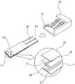
도1은 본 발명을 설명하기 위해 도시된 것으로, 바이오센서와 측정장치(미도시)의 소켓을 나타내는 사시도이다. 도1의 <a>는 바이오센서와 소켓(30)이 분리된 상태를 나타내는 것이고, <b>는 바이오센서와 소켓(30)이 결합된 상태를 나타내고 있다. 본 발명의 이해를 도모하고자 바이오센서와 측정장치 간의 연결을 위한 노드[연결노드]의 예시적 용어로서 소켓을 사용하기로 하며, 이 연결노드가 소켓, 커넥터, 단자, 전기 접속 기구, 배선 연결 매개체, 플러그 등과 같이 전기/전자 장치 간의 연결을 위한 모든 수단을 포함하는 것으로 이해하는 것이 바람직하다.1 is a perspective view illustrating a socket of a biosensor and a measuring device (not shown), which is illustrated to explain the present invention. 1 shows a state in which the biosensor and the
도1을 참조하여 살펴보면, 바이오센서는 반응부(12), 혈액 삽입부(11), 전극(13), 도선(14, 15)을 포함한다. 혈액 삽입부(11)는 혈액을 바이오센서에 도입시키는 공간이다. 반응부(12)는 도입된 혈액과 바이오센서에 있는 시약의 반응이 일어나도록 하는 공간이다. 반응부(12)와 혈액 삽입부(11)가 배치된 영역을 보다 자세히 살펴보면(X 참고), 반응 시약층(21), 반응전극(22), 절연체층(23)[제1 레이어(L1)], 스페이스 형성층(24)[제2 레이어(L2)], 커버 및 밴트 형성층(25)[제3 레이어(L3)]이 각각 배치된다. 반응 시약층(21)은 바이오센서의 예정된 동작을 수행하기 위해 효소 등이 배치되는 층이다. 반응전극(22)은 일반적으로 작동 전극과 기준 전극으로 이루어지며, 각 전극은 각각의 도선(14,15)에 연결된다. 절연체층(23)은 바이오센서가 동작하는데 필요한 배선이 형성되는 곳이다. 커버 및 밴트 형성층(25)은 보호덮개 역할 및 공기 배출구 기능을 한다. 스페이스 형성층(24)은 반응부(12)에 모세관 현상을 위한 예정된 공간을 확보하기 위해 배치되는 기판이다. 여기서 혈액은 대표적인 분석 대상 물질을 나타내는 것으로서 본 발명에서 하나의 예시이다.Referring to FIG. 1, the biosensor includes a
전극(13)은 바이오센서가 소켓(30)에 연결되었을 때에 센서 삽입 감지, 분석 대상 물질 감지 등의 기능을 위한 수단이다. 예컨대, 측정장치는 이 전극(13)이 소켓(30)의 핀단자에 접속되면 바이오센서가 연결되었음을 감지하고 이 전극(13)을 통해 분석 대상 물질의 종류가 무엇인지를 감지하게 된다. 반응부(12)에서 반응이 일어나는 것에 대응하여 기준전극과 작동전극에서 전류 흐름이 발생되고 이 전류가 소켓(30)을 통해 측정장치에 전달된다. 측정장치에서는 상기 전류의 값을 토대로 이에 대응되는 시료(목적물질, 예; 혈액의 혈당 등)의 농도 등을 산출한다.The
도2는 본 발명을 설명하기 위해 도시된 것으로, 스위치를 사용하는 바이오센서 및 측정장치의 소켓을 나타내는 사시도이다.2 is a perspective view illustrating a socket of a biosensor and a measuring device using a switch, which is illustrated to explain the present invention.
도2를 참조하여 살펴보면, 바이오센서는 혈액 삽입부(41), 반응부(42), 도선(43,44)을 포함한다. 또한, 반응부(42)와 혈액 삽입부(41)가 배치된 영역을 보다 자세히 살펴보면(Y 참고), 반응 시약층(21), 반응전극(22), 절연체층(23), 커버 및 밴트 형성층(25), 스페이스 형성층(24)이 각각 배치된다.Referring to FIG. 2, the biosensor includes a
도1에 도시된 바이오센서의 전극(14)이 소켓(30)의 단자에 연결되면 측정장치는 바이오센서가 연결되었음을 감지하게 된다. 그러나, 도2에 도시된 바이오센서에는 전극(14)이 구비되어 있지 않고, 측정장치가 소켓(50)에 있는 스위치(51)를 이용하여 바이오센서가 연결되었음을 감지하게 된다.When the
도3은 본 발명을 설명하기 위해 도시된 것으로, 코드 정보를 사용하는 바이오센서와 측정장치의 소켓을 나타내는 사시도이다.3 is a perspective view illustrating a socket of a biosensor and a measuring device using code information, which is illustrated to explain the present invention.
바이오센서의 특성은 제작 공정의 환경에 민감하게 영향을 받는다. 이를 생산 공정별로 보정하기 위한 방법으로서 일반적으로 코드 정보[생산, 품질, 성능 등의 바이오센서의 특성 정보] 보정 방법을 사용한다. 도3에 도시된 바와 같이 메모리 칩(Memory IC,61) 등의 전자부품 또는 저항, 콘덴서, 인덕터 등의 RLC 수동 및 능동 소자를 이용해 코드 정보를 저장(구성)해 두어 측정장치가 해당 코드 정보를 읽는다. 다른 방식으로는 코드 정보에 대응되는 색깔 또는 바코드를 바이오센서에 형성해 측정장치가 이를 인식하는 광학적 방법, 사용자가 측정장치의 버튼을 이용해 바이오센서의 코드 정보를 직접 입력하는 방법 등이 있다. 즉, 어떤 생산 공정에서 제조되었는지에 대한 코드 정보를 메모리 칩(61)에 저장하고, 소켓(70)에 연결되었을 때, 소켓에 연결된 측정장치가 메모리 칩(61)에 저장된 코드 정보를 인식하는 것이다. 물리적인 코드 정보를 바이오센서가 저장하고 있는 경우에는 접촉패드(63)를 통해 코드 정보가 소켓(70)으로 전달된다.The characteristics of the biosensors are sensitive to the environment of the manufacturing process. As a method for correcting this for each production process, a code method [characteristic information of biosensors such as production, quality, and performance] is generally used. As shown in FIG. 3, code information is stored (configured) by using electronic components such as a
도3에서는 바이오센서가 절연체층(62) 및 접촉패드(63)를 구비하고, 소켓(70)은 스위치(71)를 구비하고 있는 것으로 도시하였고, 바이오센서의 구동에 필요한 다른 영역은 표시하지 않았다. 만약, 코드 정보를 저장하는 메모리 칩(61)이 없는 경우에는 바이오센서가 어떤 공정에서 제조되었는지를 알 수 있는 코드 정보를 사용자가 직접 측정장치에 입력해야 한다.In FIG. 3, the biosensor includes an
지금까지 살펴본 바와 같이, 바이오센서에 시료(예; 혈액 등)을 떨어뜨렸을 때에 일어나는 전기화학 반응에 대해서 바이오센서는 이를 전기신호로 변환하고, 변환된 전기신호는 바이오센서가 측정장치에 연결되었을 때에 측정장치에 전달되도록 되어 있다. 이를 위해, 바이오센서는 2개 이상의 전극이 형성되어 있는 층, 효소혼합물이 도포되어 있는 층, 모세관 현상을 유도하여 시료를 흡입할 수 있는 스페이스 구조층, 커버 및 밴트층 등이 필요하다. 측정장치는 바이오센서의 삽입을 감지하고, 바이오센서에서 전기화학적인 반응을 일으키도록 전기신호[전압(DC 전압 또는 AC 전압) 또는 전류 등]를 인가하고, 이로부터 발생하는 전기신호[전류 또는 전압 또는 전하 등]를 해석하고, 그 측정 결과값을 저장 및 표시하는 기능 등을 가지고 있다.As we have seen, for the electrochemical reactions that occur when a sample (eg, blood, etc.) is dropped onto the biosensor, the biosensor converts it to an electrical signal, which is converted when the biosensor is connected to the measuring device. It is intended to be delivered to the measuring device. To this end, the biosensor requires a layer in which two or more electrodes are formed, a layer in which an enzyme mixture is applied, a space structure layer, a cover, and a vent layer, which can induce a sample by inducing capillary phenomenon. The measuring device detects the insertion of the biosensor, applies an electrical signal (voltage (DC voltage or AC voltage) or current, etc.) to cause an electrochemical reaction in the biosensor, and generates an electrical signal (current or voltage) generated therefrom. Or electric charges, etc., and stores and displays the measurement results.
바이오센서가 소켓에 삽입된 것을 감지하는 방법은 도1에 도시된 바와 같이, 별도의 전극을 이용하여 측정장치의 소켓에 접촉시켜 연결하거나, 도2에 도시된 바와 같이 스위치를 사용하여 바이오센서가 소켓에 삽입될 때에 스위치가 턴온되도록 하는 방법을 사용할 수 있다. 그러나, 바이오센서가 소켓에 연결되는 것을 아무리 잘 감지하도록 구성한다고 하더라도, 바이오센서와 소켓 사이의 연결부분에 대한 접촉 임피던스 값이 생길 수 밖에 없다. 도면을 참조해 2 전극 구성의 바이오센서[즉 바이오센서와 측정장치간의 신호전달부가 2개의 도선으로 이루어진 바이오센서]를 예로 들어 설명하였으나, 2 전극은 물론, 3 전극, 그 이상의 전극 구성의 바이오센서와 측정장치간에는 접촉 임피던스 값이 훨씬 더 크게 생길 수 밖에 없음을 당업자 수준에서 이해할 수 있을 것이다.The method of detecting that the biosensor is inserted into the socket is connected to the socket of the measuring device using a separate electrode as shown in FIG. 1, or as shown in FIG. A method can be used that causes the switch to turn on when inserted into the socket. However, even if the biosensor is configured to detect how well it is connected to the socket, the contact impedance value of the connection between the biosensor and the socket will be generated. Referring to the drawings, a biosensor having a two-electrode configuration (that is, a biosensor consisting of two conductive wires having a signal transmission portion between the biosensor and the measuring device) has been described as an example. It will be appreciated by those skilled in the art that the contact impedance between the measuring device and the measuring device can only be made much larger.
도4는 도1 내지 도3에 도시된 바이오센서와 측정장치의 소켓에 대한 등가 회로도이다. 여기서, 바이오센서와 측정장치는 별개의 장치로 구성되어 있다.FIG. 4 is an equivalent circuit diagram of a socket of the biosensor and the measuring device shown in FIGS. 1 to 3. Here, the biosensor and the measuring device are composed of separate devices.
바이오센서와 측정장치가 소켓 등을 통해 결합되었을 때 바이오센서의 전극과 측정장치간에 발생하는 임피던스 성분을 도4에 등가적으로 표현하였다. 여기서 'W'(working)는 작동전극을 나타내고, 'R'(reference)은 기준전극을 나타낸다. 임피던스(Z11, Z12)는 바이오센서 상에 위치하는 연결 도선에 의해 발생되는 도선 임피던스를 나타낸 것이고, 임피던스(Z21, Z22)는 측정장치의 소켓 핀단자와 바이오센서에 있는 도선간의 접촉으로 발생하는 접촉 임피던스를 나타낸 것이다. 이러한 임피던스는 서로 직렬로 연결되어 측정 정확도에 영향을 미치고, 바이오센서의 감지 불량을 발생시키는 원인이 되기도 한다. 특히, 앞서 언급한 바와 같이 접촉 임피던스(Z21, Z22)는 바이오센서와 측정장치가 분리되어 구성되어 있는 경우에 어쩔 수 없이 생기는 것으로, 이 접촉 임피던스(Z21, Z22)로 인해 바이오센서의 동작상 민감도를 높이는데에 한계가 있다.An impedance component generated between the electrode of the biosensor and the measuring apparatus when the biosensor and the measuring apparatus are coupled through a socket is equivalently represented in FIG. 4. Here 'W' (working) represents the working electrode, 'R' (reference) represents the reference electrode. Impedances Z11 and Z12 represent lead impedances generated by connecting leads located on the biosensor. Impedances Z21 and Z22 are contacts generated by contact between the socket pin terminals of the measuring device and the leads in the biosensor. Impedance is shown. These impedances are connected in series to each other, affecting the measurement accuracy, and may cause a detection failure of the biosensor. In particular, as mentioned above, the contact impedances Z21 and Z22 are inevitably generated when the biosensor and the measuring device are configured separately, and the contact impedances Z21 and Z22 are used to determine the operational sensitivity of the biosensor. There is a limit to raising.
따라서 본 발명은 이를 해결하기 위해, 바이오센서부와 측정장치를 하나로 구성한 바이오 센싱장치를 제안한다. 즉 본 발명은 바이오센서부와 측정장치를 하나의 장치로(일체형으로) 구현한 것이다.
Therefore, the present invention proposes a bio-sensing device composed of a biosensor unit and a measuring device as one. That is, the present invention implements the biosensor unit and the measuring device as one device (in one type).
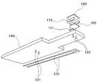
도5a 내지 도5c는 본 발명의 제1 실시예에 따른 바이오 센싱장치를 나타내는 사시도이다. 도5a는 경유구멍A(132)을 갖는 바이오센서부가 구비된 바이오 센싱장치의 상단 사시도이며, 도5b는 도5a에 도시된 바이오 센싱장치의 하단 사시도이다.5A to 5C are perspective views illustrating a biosensor according to a first embodiment of the present invention. FIG. 5A is a top perspective view of a bio sensing device equipped with a biosensor unit having a
도5a와 도5b에 도시된 바와 같이, 본 실시예에 따른 바이오 센싱장치는 화면표시부(110), 도선(120), 경유구멍A(132), 경유구멍B(131), 신호처리부(130), 절연체층(140), 반응전극(151), 반응 시약층(160), 스페이스층(170) 및 커버(180)를 포함한다.As shown in FIGS. 5A and 5B, the bio-sensing device according to the present embodiment includes the
본 발명에 있어 절연체층(140)은 절연성 기판 상에 전도성 전극을 형성할 수 있는 어떠한 소재라도 무방하다. 전도성 전극을 절연성 기판 상에 형성하는 것과 관련된 산업적 기술로는 쉐도우 마스크를 사용하는 스퍼터링에 의해 전도성 전극을 형성하는 방식, 전극을 통상의 스퍼터링으로 형성하고 통상의 포토리소그래피 또는 레이저를 이용하여 형성하는 방식, 스크린 프린팅, 무전해 도금법, 전해질 도금법 등을 사용하여 전극을 형성하는 방식 등 다양한 방식을 적용할 수 있다. 예를 들어 인쇄 전자(printing electronics)를 이용해 필름, 유리, 실리콘, 플라스틱, 섬유, 종이 등의 다양한 소재를 기판으로 하여 전도성 잉크, 전도성 페이스트 등으로 패턴을 형성하여 절연체층(140)을 구현할 수 있으며, 산업적으로 널리 사용되고 있는 PCB 등이 절연체층(140)의 대표적이 예시이다. 이러한 절연체층은 본 발명의 다른 모든 실시예에서도 동일하게 적용된다.In the present invention, the
상기 반응 전극(151), 반응 시약층(160), 스페이스층(170) 및 커버(180)가 있는 곳이 바이오센서부이다. 바이오센서부는 구비된 물질로 인해 화학반응이 생기는 곳을 말한다. 반응 시약층(160), 스페이스층(170) 및 커버(180)에 의해 반응 챔버가 구현된다. 반응 시약층(160)은 바이오센싱 장치가 예정된 반응동작을 하기 위한 물질이 배치되는 곳이다.The biosensor unit includes the
스페이스층(170)은 반응 시약층(160)의 주변을 감싸고 있는 층이다. 커버(180)는 반응 시약층(160)을 덮고 있는 층이다. 스페이스층(170) 및 커버(180)에 의해 형성된 공간은 모세관 현상이 진행될 수 있는 공간이다. 절연체층(140)은 회로가 배치되는 기판이다.The
반응전극(151)은 반응 시약층에서 일어나는 화학 반응에 대응하는 전기전 신호를 발생시키기 위한 전극이다. 즉, 반응전극(151)은 반응시약과 분석 대상 물질(예; 혈액의 혈당 등)에 의해 일어난 산화환원 반응에 상응하는 아날로그 전기신호를 생성하는 것이다. 반응전극(151) 중 하나는 작동전극이고, 나머지 하나는 기준전극이 된다. 여기서는 반응전극은 전기화학적 측정에 있어 최소한 2개 전극이 필요해서 이를 표현한 것이며, 3개, 5개, 8개 등 그 개수는 다양하게 될 수 있다.The
화면표시부(110)는 바이오 센싱 결과를 표시하기 위한 것이다. 화면표시부(110)는 측정 결과값(예; 혈당값 등)을 사용자에게 알려주기 위한 수단이며, 화면표시부 외에 음성/음향 출력수단(스피커, 부저 등)도 가능하다. 화면표시부(110)는 LCD, 전자종이, LED[주; 측정 결과값을 색깔/밝기 등으로서 표현)도 가능하다.The
신호 처리부(130)는 반응 전극(151)에서 발생되어 경유구멍A(132), 도선(120), 경유구멍B(131)를 거쳐 전달받은 아날로그 전기신호를 디지털 전기신호로 변환하는 신호 변환부와, 상기 디지털 전기신호로부터 상기 분석 대상 물질의 측정 결과값을 생성하는 연산부와, 상기 생성된 측정 결과값을 표시하는 출력부를 포함한다. 즉, 신호처리부(130)는 도선(120)을 통해 제공되는 반응 시약층에서의 반응결과에 대한 전기신호를 수신받아 화면표시부에 그에 대응하는 결과값이 표시될 수 있도록 한다. 절연체층(140)은 도선(120)이 형성되는 층이다.The
도선(120)은 바이오 센서부와 신호 처리부를 전기적으로 연결, 즉 반응 전극(151)과 신호 처리부(130)간의 인가 전압, 전기화학반응에 따른 아날로그 전기신호(전류 또는 전압 등)를 전달하는 수단이다. 이러한 도선은 본 발명에서 신호 전달부인 것이다.The
도 5a 및 5b에 도시된 바이오 센싱장치의 동작 과정을 전기화학 전류법(ampero metry)의 혈당 측정으로 예를 들어 설명하면 다음과 같다.The operation of the biosensing device illustrated in FIGS. 5A and 5B will be described with an example of blood glucose measurement using an electrochemical current method.
신호처리부(130)에서 전압을 인가하면 이 전압은 경유구멍B(131), 도선(120), 경유구명A(132)를 거쳐 반응전극(151)에 인가된다. 반응전극(151)에 전압이 인가됨에 따라, 반응시약과 그 위에 도입된 분석 대상 물질(예; 혈액의 혈당 등)간의 전기화학반응에 따라 아날로그 신호(전류)가 발생된다. 이 전류는 반응전극(151)으로부터 경유구멍A(132), 도선(120), 경유구멍B(131)를 거쳐 신호처리부(130)로 전달된다. 신호처리부(130)는 연산처리를 통해 전류에 해당되는 측정 결과값(예; 분석 대상 물질의 농도인 혈당값 등)을 도출한다. 이 실시예의 특징은 경유구멍(131,132)를 통해 신호 전달 경로를 갖도록 한 것이며, 이에 따라 도선(120)이 절연체층 하측에 배치되는 구성을 가지고 있다.When the voltage is applied by the
도5c는 멀티레이어를 구비하는 경우를 나타내는 구조이다.Fig. 5C is a structure showing a case where a multilayer is provided.
도5c를 참조하여 살펴보면, 도선(120)을 제2 절연체층(142) 상에 구현하거나, 제1 절연체층(141) 하측에 도선(120)을 구성하고 이를 제2 절연체층(142)가 덮는 구조로 구현할 수도 있다.Referring to FIG. 5C, the
도5a 내지 도5c에서는 일반적인 신호처리부의 구성을 변형하지 않기 위해 경유구멍B(131)를 구성했으나, 이는 다양하게 변형이 가능하다. 즉, 도5a 내지 도5c에서는 신호처리부와 경유구멍B(131) 사이에 도선이 배치된 형태로 되어 있으나, 이 도선 없이 신호처리부 핀단자 바로 앞에 경유구멍 만을 구성하거나, 도선 및 경유구멍B(131) 없이 신호처리부의 핀단자를 절연체층의 하측으로 뽑아서 핀단자와 도선이 직접 연결되도록 구성할 수도 있다.
In FIGS. 5A to 5C, a
도 5d는 본 발명의 다른 실시예에 따른 바이오 센싱장치를 나타내는 사시도이다.Figure 5d is a perspective view showing a bio-sensing device according to another embodiment of the present invention.
도5d에 도시된 바와 같이, 본 실시예에 따른 바이오 센싱장치(100A)는 화면표시부(110A), 도선(120A), 신호처리부(130A), 절연체층(140A), 반응전극(151A), 반응 시약층(160A), 스페이스층(170A) 및 커버(180A)를 포함한다. 화면표시부(110A)는 바이오 센싱 결과를 표시하기 위한 것이다. 여기서 반응 전극(151A), 반응 시약층(160A), 스페이스층(170A) 및 커버(180A)가 있는 곳이 바이오 센서부이다.As shown in FIG. 5D, the
바이오 센서부는 구비된 물질로 인해 화학반응이 생기는 곳을 말한다. 반응 시약층(160A), 스페이스층(170A) 및 커버(180A)에 의해 반응 챔버가 형성되며, 반응 시약층(160A)은 바이오센서가 예정된 반응동작을 하기 위한 물질이 배치되는 곳이다. 스페이스층(170A)은 반응 시약층(160)의 주변을 감싸고 있는 층이다. 커버(180A)는 반응 시약층(160A)을 덮고 있는 층이다. 스페이스층(170A) 및 커버(180A)에 의해 형성된 공간은 모세관 현상이 진행될 수 있는 공간이다. 반응전극(151A)은 반응 시약층에서 일어나는 화학 반응에 대응하는 전기적 신호를 발생시키기 위한 전극이다. 화면표시부(110A)는 LCD 장치 또는 LED 장치를 이용할 수 있으며, 기타 화면을 표시하는 어떤 장치도 가능하다. 특히 최근에 개발되고 있는 전자종이를 이용할 수 있다. 도선(120A)은 반응전극(151A)과 신호처리부(130A)를 전기적으로 연결하기 위한 것이다. 여기서 반응전극(151A)과 도선(120A)이 구분되어 있는데, 바이오 센싱장치의 제조 공정에 따라 반응전극과 도선이 일체로 패턴화되어 형성될 수 있다. 신호처리부(130A)는 도선(120A)을 통해 제공되는 반응 시약층에서의 반응결과에 대한 전기신호를 수신받아 화면표시부에 그에 대응하는 결과값이 표시될 수 있도록 한다. 절연체층(140A)은 도선(120A)이 형성되는 층이다.
The biosensor part refers to a place where a chemical reaction occurs due to a material provided. The reaction chamber is formed by the
도1 내지 도4에서 설명하였듯이, 종래기술에서는 서로 물리적으로 분리된 바이오센서와 측정장치가 소켓 등으로 연결되어야 바이오센서에서 일어난 산화환원 반응에 상응하는 아날로그 전기신호를 측정장치로 전달하여 그 반응상태를 확인할 수 있었다. 이 과정에서 연결부분의 임피던스 값이 분석 대상 물질의 값을 측정하는데 방해요소가 되어 정확도를 떨어뜨렸다.1 to 4, in the prior art, a biosensor and a measuring device that are physically separated from each other must be connected to a socket or the like to transmit an analog electric signal corresponding to the redox reaction generated in the biosensor to the measuring device and the reaction state thereof. Could be confirmed. In this process, the impedance value of the connection part was an obstacle to measuring the value of the analyte, which reduced the accuracy.
그러나, 본 발명에 의한 바이오 센싱장치는 하나의 레이어에 바이오 센서부와 이 바이오 센서부에서 반응된 결과를 신호 처리할 수 있는 신호처리부가 있기 때문에, 종래기술과 달리 바이오센서가 측정장치에 물리적 연결되는 소켓 등의 연결노드에 의한 임피던스 성분이 없어지게 된다. 또한, 본발명에서는 도1 내지 도4에 도시된 바이오센서에 필요한 센서 삽입 감지, 분석 대상 물질 감지 등의 수단으로서의 전극이 필요없고, 이러한 전극의 오류로 인한 에러를 완전히 배제할 수 있다. 도4에 도시된 접촉 임피던스(Z21, Z22)가 없기 때문에, 바이오 센서부에서 전기화학반응에 의해 생성되는 신호를 더욱 민감하게 내부적으로 처리할 수 있기 때문에, 바이오 센싱장치는 더욱 정확한 측정이 가능해진다. 이러한 본 발명에 있어 바이오 센서부의 반응 전극과 신호 처리부 간을 신호 전달부[도선]로서 전기적 연결을 한 것인데, 이는 반응 전극과 신호 전달부가 전기전도성 물질을 포함한 것임을 알 수 있다.However, the biosensor according to the present invention has a biosensor in one layer and a signal processor for signal processing the result of the reaction from the biosensor, so unlike the prior art, the biosensor is physically connected to the measuring device. Impedance components by connection nodes such as sockets are eliminated. In addition, in the present invention, an electrode as a means for sensor insertion detection, analyte detection, etc. required for the biosensor shown in FIGS. 1 to 4 is unnecessary, and an error due to an error of the electrode can be completely excluded. Since there are no contact impedances Z21 and Z22 shown in FIG. 4, the biosensor can more accurately internally process signals generated by the electrochemical reaction in the biosensor section, thereby enabling more accurate measurement. . In the present invention, the electrical sensor is connected between the reaction electrode and the signal processor as a signal transmitter [conductor], which can be seen that the reaction electrode and the signal transmitter includes an electrically conductive material.
또한, 본 실시예에 따른 바이오 센싱장치는 절연체층(140) 상에 바이오 센싱장치에 대한 식별정보를 저장하기 위한 기억수단(미도시)을 더 포함할 수 있다. 식별정보는 화면표시부(110)를 통해서 표시할 수도 있고 추가로 구비된 표시부를 통해서 할 수도 있다. 여기서 식별정보는 분석 대상 물질의 종류, 측정 조건, 생산정보, 사용자 정보 중 적어도 어느 하나로 구성할 수 있다. 예를 들어, 가족 구성원 중에 특정한 바이오 센싱장치는 누구를 위한 것인지 식별하기 쉽도록, 바이오 센싱장치가 식별정보를 저장하고 표시할 수 있는 것이다.In addition, the bio-sensing device according to the present embodiment may further include a storage means (not shown) for storing identification information on the bio-sensing device on the
또한, 본 발명의 일체형 바이오 센싱장치는 1회용으로서 쓰고 버릴 수 있어 언제, 어디서나 편리하게 사용할 수 있다[여행 중 사용, 휴대성 보장 등].
In addition, the integrated bio-sensing device of the present invention can be used and discarded as a single use, and can be conveniently used anytime and anywhere (use during travel, guaranteeing portability, etc.).
도6 내지 도12는 본 발명의 바이오 센싱장치에 대한 다양한 실시예를 도시하고 있다. 이하에 설명하는 다양한 실시예에 따른 바이오 센싱장치는 특징되는 부분만 설명하며, 전술한 바이오 센싱장치의 내부 구성요소를 선택적으로 구비할 수 있다. 또한, 이하에서 설명하는 다양한 실시예에 있는 각 특징은 서로 다양하게 조합되어 바이오 센싱장치를 구성할 수 있다.6 to 12 illustrate various embodiments of the biosensing device of the present invention. The biosensing device according to various embodiments described below will be described only for the features, and may be provided with the internal components of the above-described bio-sensing device. In addition, each feature in the various embodiments described below may be combined in various ways to constitute a bio-sensing device.
도6은 본 발명의 제2 실시예에 따른 바이오 센싱장치를 나타내는 사시도이다. 도6에 도시된 바와 같이, 본 실시예에 따른 바이오 센싱장치는 화면표시부(211), 도선(212), 신호처리부(213), 절연체층(214), 반응전극(221, 222), 반응 시약층(223), 스페이스층(224), 및 커버(225)를 포함한다.6 is a perspective view showing a bio-sensing device according to a second embodiment of the present invention. As shown in FIG. 6, in the biosensor according to the present embodiment, the
본 실시예에 따른 바이오 센싱장치는 제1 레이어(210)와 제2 레이어(220)로 구성되어 있고, 제1 레이어(210)는 도5에 도시된 절연체층 등으로 구현할 수 있고 제2 레이어(220)는 전극을 포함하는 플렉시블(Flexible) 절연체층 등으로 구현할 수 있다. 물론 제1 레이어(210)와 제2 레이어(220)를 동일한 소재의 기판으로 구현할 수도 있다. 바람직한 예시로서 제1 레이어(210)는 PCB 등으로 구현할 수 있고 제2 레이어(220)는 Flexible PCB 등으로 구현할 수 있다. 제1 레이어는 본발명의 측정장치에 해당되는 부분이며, 제2 레이어는 본발명의 바이오센서부에 해당되는 부분이다.The biosensor according to the present embodiment is composed of a
제1 레이어(210)와 제2 레이어(220)는 경성/연성 인쇄 회로 기판 접합 기술(예; 산업적으로 널리 사용되고 있는 R/F(rigid/flexible) PCB 접합 기술 등)을 이용하여 접합(215 참조)하는 것이 본 실시예에 따른 바이오 센싱장치의 특징이다. 이렇게 2개의 레이어를 이용함으로서, 바이오 센싱 결과의 정확성, 재현성 등에 큰 영향을 미치는 반응 시약이 배치된 레이어를 별도로 제작하고, 나머지 전자 부품으로 구성되는 신호 처리부가 있는 레이어를 접합함으로서 바이오 센싱장치의 제조공정 신뢰성을 향상시킬 수 있다.
The
도7은 본 발명의 제3 실시예에 따른 바이오 센싱장치를 나타내는 사시도이다. 도7에 도시된 바와 같이, 본 실시예에 따른 바이오 센싱장치는 화면표시부(211), 도선(212), 신호처리부(213), 절연체층(214), 반응전극(321, 322), 반응 시약층(323), 스페이스층(324) 및 커버(325)를 포함한다.7 is a perspective view showing a bio-sensing device according to a third embodiment of the present invention. As shown in FIG. 7, in the biosensor according to the present embodiment, the
본 실시예에 따른 바이오 센싱장치는 제1 레이어(210)와, 제2 레이어(320)를 포함하고, 제1 레이어(210)와, 제2 레이어(320)는 히트 실(Heat Seal,310)을 이용하여 연결하는 것이 특징이다.
The biosensor according to the present embodiment includes a
도8은 본 발명의 제4 실시예에 따른 바이오 센싱장치를 나타내는 사시도이다. 도8에 도시된 바와 같이, 본 실시예에 따른 바이오 센싱장치(400)는 화면표시부(430), 도선(420), 신호처리부(440), 절연체층(410), 반응전극(461, 462), 반응 시약층(470), 스페이스층(480) 및 커버(490)를 포함한다.8 is a perspective view showing a bio-sensing device according to a fourth embodiment of the present invention. As shown in FIG. 8, the
본 실시예에 따른 바이오 센싱장치는 반응전극(461, 462)이 와이어본딩(450)을 이용하여 도선(420)과 연결되어 있는 것이 특징이다.In the biosensor according to the present embodiment, the
도9는 본 발명의 제5 실시예에 따른 바이오 센싱장치를 나타내는 사시도이다. 도9에 도시된 바와 같이, 본 실시예에 따른 바이오 센싱장치는 화면표시부(510), 도선(550), 신호처리부(520), 절연체층(530), 반응전극(561, 562), 반응 시약층(570) 및 커버(590)를 포함한다.9 is a perspective view showing a bio-sensing device according to a fifth embodiment of the present invention. As shown in FIG. 9, in the biosensor according to the present embodiment, the
본 실시예에 따른 바이오 센싱장치는 전기 전도성 범프(bump, 540)를 이용하여 반응 전극(561,562)과 도선(550)을 연결한 것이 특징이다. 즉, 이러한 전기 전도성 범프(540)를 이용함으로서, 본발명의 제5 실시예에서는 전기 전도성 범프(540)와 반응 전극(561,562) 사이에 모세관 공간이 형성되며, 따라서 별도의 스페이스층과 밴트홀(vent hole)이 필요하지 않는 것이다.The biosensor according to the present embodiment is characterized in that the
예컨대, 반응 시약층(570)이 전기 전도성 범프(540)와 연결되어 있기 때문에, 별도의 밴트홀이 필요 없다. 또한, 전기 전도성 범프(540)를 다양한 형태로 구성하게 되면, 반응 시약층(570)이 기울어 지게 할 수도 있으며, 그로 인해 시료 도입이 더 잘 될 수 있다. 또한, 전기 전도성 범프(540)에 의해, 순수하게 반응하는 면적만 반응 시약층으로 효율적으로 만들 수 있어, 원가절감 및 수율 향상을 기대할 수 있다.For example, since the
도9의 하단에는 전기 전도성 범프와 반응 전극 및 반응 시약층이 결합된 것이 도시되어 있다.
In the lower part of FIG. 9, an electrically conductive bump, a reaction electrode, and a reaction reagent layer are illustrated.
도10은 본 발명의 제6 실시예에 따른 바이오 센싱장치를 나타내는 사시도이다. 도10에 도시된 바와 같이, 본 실시예에 따른 바이오 센싱장치는 제1 레이어(610), 제2 레이어(620), 제3 레이어(630), 반응전극(661, 662), 반응 시약층(670) 및 커버(690)를 포함한다.10 is a perspective view showing a bio-sensing device according to a sixth embodiment of the present invention. As shown in FIG. 10, the biosensor according to the present embodiment includes a
본 실시예에 따른 바이오 센싱장치는 다수의 레이어를 포함하고 있는 것을 특징으로 하며, 각 레이어(610,620,630)는 각각 절연체층으로 사용될 수 있다. 즉, 각 레이어(610,620,630) 중 어느 하나의 레이어에 바이오 센싱장치에 필요한 배선을 형성할 수도 있고, 각 레이어(610,620,630)에 일부분의 배선을 각각 형성할 수도 있다.The biosensor according to the present embodiment is characterized in that it comprises a plurality of layers, each
또한, 도10에 도시된 바이오 센싱장치는 다수의 레이어를 사용하는 것을 강조하기 위해, 다른 필요한 부품에 대한 표기를 생략하였으나, 전술한 바이오 센싱장치의 동작에 필요한 각 부품을 포함한다.In addition, in order to emphasize the use of multiple layers, the biosensing apparatus shown in FIG. 10 omits the description of other necessary components, but includes each component necessary for the operation of the above-described biosensing apparatus.
도11은 본 발명의 제7 실시예에 따른 바이오 센싱장치를 나타내는 사시도이다. 도11에 도시된 바와 같이, 본 실시예에 따른 바이오 센싱장치(600A)는 제1 레이어(610), 제2 레이어(620), 제3 레이어(630), 반응전극(661, 662), 반응 시약층(670), 스페이스층(680) 및 커버(690)를 포함한다.11 is a perspective view showing a bio-sensing device according to a seventh embodiment of the present invention. As shown in FIG. 11, the
본 실시예에 따른 바이오 센싱장치는 다수의 레이어를 포함하고 있는 것이 특징이며, 각 레이어(610,620,630)는 각각 절연체층으로 사용될 수 있다. 즉, 각 레이어(610,620,630) 중 어느 하나의 레이어에 바이오 센싱장치에 필요한 배선을 형성할 수도 있고, 각 레이어(610,620,630)에 일부분의 배선을 각각 형성할 수도 있다. 또한, 본 실시예에 따른 바이오 센싱장치는 스페이스층(680)을 구비하고 있는 것이 도10에 도시된 바이오 센싱장치와 대비되는 특징이다. 예컨대, 도 10의 바이오 센싱장치는 커버(690)의 구조를 돔과 같이 하여 스페이스층의 기능을 함께 하며, 이는 스페이스층의 구성이 구비되지 않아도 되도록 한 것이다. 이러한 커버의 구조는 본 발명의 다른 모든 실시예에도 적용될 수 있다.
The biosensor according to the present embodiment is characterized by including a plurality of layers, each
도12는 본 발명의 제8 실시예에 따른 바이오 센싱장치를 나타내는 사시도이다. 도12에 도시된 바와 같이, 본 실시예에 따른 바이오 센싱장치는 화면표시부(700), 집적회로(IC; Integrated Circuit)(710), 도선(720), 반응 전극(761,762), 반응 시약층(770), 스페이스층(780) 및 커버(790)를 포함한다.12 is a perspective view showing a bio-sensing device according to an eighth embodiment of the present invention. As shown in FIG. 12, the biosensor according to the present embodiment includes a
본 실시예에 따른 바이오 센싱장치는 능동, 수동 소자로 신호 처리부를 포함해 소자 내에 코드 정보 등과 같은 각종 정보까지도 포함될 수 있도록 집적회로(710)를 구성한 것이다. 즉 정보 저장을 위한 별도의 기억수단을 바이오 센싱장치에 추가적으로 구성하지 않고서 신호 처리부에 코드 정보 등을 포함시켜 집적회로(710)로 구현한 것이다. 예시적으로 이러한 집적회로(710)는 통상적으로 SoC(System on Chip)라 불리우는 하나의 IC 칩 등으로 구현할 수 있다. 한편, 이와 같은 본 실시예의 구성은 본 명세서에서 설명하는 다른 모든 실시예에 적용 가능하다. 또한, 도6에 도시된 제2 실시예에 따른 바이오 센싱장치와 같이, 2개의 레이어를 경성/연성 인쇄 회로 기판 접합 기술(예; R/F(rigid/flexible) PCB 접합 기술 등)을 이용하여 접합(730 참조)할 수도 있다.
The biosensing device according to the present exemplary embodiment configures the
또한, 본 발명은 바이오 센서부를 다수 구비하여 다양한 종류의 바이오 센싱을 수행할 수 있는 바이오 센싱장치를 도13 내지 도15를 참조하여 제안한다.In addition, the present invention proposes a bio sensing device capable of performing various types of bio sensing with a plurality of bio sensor units with reference to FIGS. 13 to 15.
도13은 본 발명의 제9 실시예에 따른 다수의 바이오 센서부를 구비한 바이오 센싱장치를 나타내는 사시도이다. 도14는 본 발명의 제10 실시예에 따른 다수의 바이오 센서부를 구비한 바이오 센싱장치를 나타내는 사시도이다. 도15는 본 발명의 제11 실시예에 따른 다수의 바이오 센서부를 구비한 바이오 센싱장치를 나타내는 사시도이다.FIG. 13 is a perspective view illustrating a bio sensing device including a plurality of bio sensors according to a ninth embodiment of the present invention. 14 is a perspective view illustrating a biosensing device including a plurality of biosensors according to a tenth embodiment of the present invention. FIG. 15 is a perspective view illustrating a biosensor having a plurality of biosensors according to an eleventh embodiment of the present invention.
도13과 도14에 도시된 바와 같이, 바이오 센싱장치가 하나의 화면표시부(예를 들어 도13의 81, 도14의 97)와, 신호처리부에 다수의 바이오 센서부를 구비하게 되면, 하나의 바이오 센싱장치로 다양한 바이오 센싱동작을 수행할 수 있다. 다수의 바이오 센서부(예를 들어 도13의 82, 도14의 91,92,93)는 각각 반응전극과, 바이오 센싱동작을 위한 물질을 구비한다. 또한 다수의 바이오 센서부에는 각각 구비된 전극에서 신호처리부로 전기신호를 전달하기 위한 도선(신호 전달부)이 바이오 센서부의 수에 대응하여 배치되어 있다.As shown in FIGS. 13 and 14, when the biosensor includes one screen display unit (eg, 81 in FIG. 13 and 97 in FIG. 14) and a plurality of biosensor units in the signal processor, one bio Various bio-sensing operations can be performed by the sensing device. The plurality of biosensor units (eg, 82 of FIG. 13 and 91, 92, 93 of FIG. 14) each include a reaction electrode and a material for a biosense operation. In addition, a plurality of biosensor units are arranged to correspond to the number of biosensor units, respectively, for conducting electric signals from the electrodes provided to the signal processor.
바이오 센싱 동작을 위한 물질은 바이오 센서부에 배치되는 반응 챔버에 구비되며, 반응 챔버는 전술한 다양한 실시예를 다양하게 적용할 수 있다. 특히, 이때 하나의 레이어를 이용할 수도 있고, 제1 레이어(예를 들면 도14의 98)와 다수의 제2 레이어(91,92,93)를 이용할 수도 있다. 하나의 레이어를 이용하는 경우에는 도5, 도8, 도9, 도10, 및 도11에 있는 바이오 센서부의 실시예를 이용할 수 있으며, 제1 레이어와 다수의 제2 레이어를 이용하는 경우에는 도6, 도7 및 도12에 도시된 다수의 바이오 센서부의 실시예를 이용할 수 있다. 여기서 바이오 센서부가 위치한 부분을 서브 레이어라 하고, 신호 처리부가 위치한 부분을 메인 레이어라고 하기로 한다.
The material for the biosensing operation is provided in the reaction chamber disposed in the biosensor unit, and the reaction chamber may variously apply the above-described various embodiments. In particular, one layer may be used at this time, or a first layer (eg, 98 of FIG. 14) and a plurality of
또한, 도13처럼 바이오 센싱장치를 구성할 때에는 일측에만 다수의 바이오 센서부를 배치시킬 수도 있고, 도14에 있는 경우처럼 화면표시부를 가운데 배치하고, 바이오 센서부(91,92,93 참조)를 모든 측면에 배치할 수 있다. 또한, 바이오 센싱장치는 그 특성상 바이오 센서부에 화학 반응을 위한 물질이 배치되기 때문에, 각 바이오 센서부를 패키징한 패키지부(도14의 95)가 더 구비되어 방습 기능을 할 수 있도록 한다. 전술한 모든 실시예에 따른 바이오 센싱장치는 앞서 도14를 참조해 설명한 방습을 위한 패키지를 추가로 구비할 수 있다. 또한, 화면표시부는 LCD 장치, LED 장치 또는 기타 정보를 표시할 수 있는 모든 디스플레이 장치를 이용할 수 있다.In addition, when configuring the bio-sensing device as shown in FIG. 13, a plurality of biosensor units may be arranged on only one side, or as shown in FIG. Can be placed on the side. In addition, since the biosensing device has a substance for chemical reaction in the biosensor unit, a package unit (95 in FIG. 14) in which the biosensor unit is packaged may be further provided to perform a moisture proof function. The biosensing device according to all the above-described embodiments may further include a package for moisture proof described with reference to FIG. 14. In addition, the screen display unit may use an LCD device, an LED device, or any display device capable of displaying other information.
또한, 도15에서처럼, 하나의 바이오 센서부(94)에 적어도 2개 이상의 전극(a,b,c,d 참조)으로 이루어진 각각의 반응전극 및 화학물질 쌍을 구비시켜, 다른 종류의 바이오 센싱동작을 하나의 바이오 센서부에서 수행할 수 있도록 구성할 수도 있다.
In addition, as shown in FIG. 15, one
지금까지 설명한 다양한 실시예에 포함된 특징을 적어도 하나 또는 다수를 선택하여 결합시킨 바이오 센싱장치를 필요에 따라 구현할 수 있다.A biosensing device in which at least one or a plurality of features included in the various embodiments described above are selected and combined may be implemented as necessary.
한편, 전술한 본 발명의 바이오 센싱장치는 임상적으로 함께 측정되어야 하는 물질, 예를 들면 혈당, 당화혈색소(HbA1c), 헤모글로빈(Hb) 등을 함께 측정할 수 있는 바이오 센싱장치를 구현하는데 적합하게 적용될 수 있다.On the other hand, the above-described bio-sensing device of the present invention is suitable for implementing a bio-sensing device that can measure the substance to be clinically measured together, for example, blood sugar, glycated hemoglobin (HbA1c), hemoglobin (Hb), etc. Can be applied.
한편, 본 발명의 모든 실시예에 따른 바이오 센싱장치를 설명하는데 있어 전원부, 버튼 등과 같은 부가적인 구성요소에 대해서는 그 상세한 설명을 생략하였다. 예시적으로 본 발명의 바이오 센싱장치는 전원부(예; 배터리, USB 연결 등), 소수의 입력부(예; 키 버튼, 액정 화면 메뉴 등) 등을 구비할 수 있다.Meanwhile, in describing the biosensor according to all embodiments of the present invention, detailed descriptions of additional components such as a power supply unit and a button are omitted. For example, the biosensor of the present invention may include a power supply unit (eg, a battery, a USB connection, etc.), a few input units (eg, a key button, a liquid crystal display menu, etc.).
지금까지 살펴본 바와 같이, 본 실시예에 따른 바이오 센싱장치는 측정장치가 전기 커넥터 또는 소켓 등의 연결노드 없이 직접 전기적으로 바이오 센서부와 연결되어 있는 구조이다. 따라서, 바이오센서부와 측정장치 사이를 연결하는 것에 따른 임피던스가 없으므로, 접촉 임피던스에 따른 신호의 왜곡이 없어서 측정 정밀도가 매우 높다.As described above, the biosensor according to the present embodiment has a structure in which the measuring device is directly connected to the biosensor unit without a connection node such as an electrical connector or a socket. Therefore, since there is no impedance due to the connection between the biosensor unit and the measuring device, there is no distortion of the signal due to the contact impedance, so the measurement accuracy is very high.
또한, 종래기술과 같이 바이오센서를 측정장치로 연결하는데 있어 바이오센서에 필요한 센서 삽입 감지, 분석 대상 물질 감지 등의 수단으로서의 전극도 필요없기 때문에, 감지에 대한 오류가 생기지 않는다. 따라서 바이오 센싱 동작을 보다 신뢰성 있게 수행할 수 있다.In addition, since there is no need for an electrode as a means for sensor insertion, analyte detection, etc. necessary for the biosensor to connect the biosensor to the measuring device as in the prior art, there is no error in detection. Therefore, the bio sensing operation can be performed more reliably.
또한, 커넥터 또는 소켓 등의 연결노드가 필요 없기 때문에 바이오 센싱장치의 제조비용이 그만큼 줄어들 수 있다.In addition, since a connection node such as a connector or a socket is not required, the manufacturing cost of the biosensor may be reduced accordingly.
이상에서 대표적인 실시예를 통하여 본 발명에 대하여 상세하게 설명하였으나, 본 발명이 속하는 기술분야에서 통상의 지식을 가진 자는 상술한 실시예에 대하여 본 발명의 범주에서 벗어나지 않는 한도 내에서 다양한 변형이 가능함을 이해할 것이다. 그러므로 본 발명의 권리범위는 설명된 실시예에 국한되어 정해져서는 안되며, 후술하는 특허청구범위뿐만 아니라 이 특허청구범위와 균등한 것들에 의해 정해져야 한다.While the present invention has been particularly shown and described with reference to exemplary embodiments thereof, it is clearly understood that the same is by way of illustration and example only and is not to be construed as limiting the scope of the present invention. I will understand. Therefore, the scope of the present invention should not be limited to the described embodiments, but should be determined by the scope of the appended claims, as well as the appended claims.
Claims (62)
Translated fromKorean분석 대상 물질과 산화환원 반응을 하는 반응 시약과, 상기 반응 시약이 고정되는 반응 챔버와, 상기 산화환원 반응이 일어나도록 하여 아날로그 전기신호를 생성하는 복수의 반응 전극을 포함하는 바이오 센서부와,
상기 아날로그 전기신호를 처리하는 신호 처리부와,
상기 아날로그 전기신호를 상기 신호 처리부로 전달하는 신호 전달부를 구비하며,
상기 복수의 반응 전극과 상기 신호 전달부는 전기전도성 물질을 포함하고, 하나의 절연체층에 형성되며,
상기 신호 처리부는,
상기 아날로그 전기신호를 디지털 전기신호로 변환하는 신호 변환부와,
상기 디지털 전기신호로부터 상기 분석 대상 물질의 측정 결과값을 생성하는 연산부와,
상기 생성된 측정 결과값을 표시하는 출력부를 구비하며,
상기 바이오 센서부 및 신호 처리부는 상기 신호 전달부에 의하여 연결되어 상기 절연체층 상에서 일체로 형성되는 것을 특징으로 하는 바이오 센싱장치.
In the electrochemical bio-sensing device,
A biosensor unit including a reaction reagent for reacting with an analyte and a redox reaction, a reaction chamber in which the reaction reagent is fixed, and a plurality of reaction electrodes for generating an analog electric signal by causing the redox reaction to occur;
A signal processor for processing the analog electric signal;
A signal transfer unit configured to transfer the analog electric signal to the signal processor,
The plurality of reaction electrodes and the signal transmission part include an electrically conductive material and are formed in one insulator layer.
The signal processing unit,
A signal converter converting the analog electric signal into a digital electric signal;
An operation unit configured to generate a measurement result value of the analysis target material from the digital electrical signal;
An output unit for displaying the generated measurement result value;
And the biosensor unit and the signal processor are integrally formed on the insulator layer by being connected by the signal transfer unit.
상기 반응 챔버는 모세관 구조를 갖는 것을 특징으로 하는 바이오 센싱장치.
The method of claim 1,
And the reaction chamber has a capillary structure.
상기 반응 전극과 상기 신호 전달부는 상기 절연체층에 형성된 제1 경유구멍을 통해 전기적으로 연결되는 것을 특징으로 하는 바이오 센싱장치.
The method of claim 1,
And the reaction electrode and the signal transmission unit are electrically connected to each other via a first via hole formed in the insulator layer.
상기 신호 전달부와 상기 신호 처리부는 상기 절연체층에 형성된 제2 경유구멍을 통해 전기적으로 연결되는 것을 특징으로 하는 바이오 센싱장치.
The method of claim 1,
And the signal transmission unit and the signal processing unit are electrically connected through a second via hole formed in the insulator layer.
상기 신호 전달부는 상기 절연체층의 하면에 형성되어 상기 제1, 제2 경유구멍의 위치에 대응되게 그 양 단부가 배치되는 것을 특징으로 하는 바이오 센싱장치.
The method according to claim 5 or 6,
The signal transmitting unit is formed on the lower surface of the insulator layer, the bio-sensing device, characterized in that both ends are disposed corresponding to the position of the first and second via hole.
상기 신호 전달부는 다른 절연체층의 일면에 형성되며, 상기 신호 전달부의 양 단부가 상기 제1, 제2 경유구멍의 위치에 대응되게 상기 다른 절연체층과 상기 절연체층이 접합되는 것을 특징으로 하는 바이오 센싱장치.
The method according to claim 5 or 6,
The signal transmission unit is formed on one surface of the other insulator layer, and the other insulator layer and the insulator layer are joined to each other so that both ends of the signal transmission unit correspond to the positions of the first and second transit holes. Device.
상기 반응 전극은 상기 신호 전달부와 와이어 본딩으로 전기적 연결되는 것을 특징으로 하는 바이오 센싱장치.
The method of claim 1,
And the reaction electrode is electrically connected to the signal transmission unit by wire bonding.
상기 반응 전극은 상기 신호 전달부와 범프로 전기적 연결되는 것을 특징으로 하는 바이오 센싱장치.
The method of claim 1,
The reaction electrode is a bio-sensing device, characterized in that electrically connected with the signal transmission portion bump.
상기 바이오 센싱장치에 대한 식별정보를 저장하기 위한 기억수단을 더 포함하는 것을 특징으로 하는 바이오 센싱장치.
The method of claim 1,
And a storage means for storing identification information of the bio-sensing device.
상기 식별정보는 분석 대상 물질의 종류, 측정 조건, 생산정보, 사용자 정보 중 적어도 어느 하나를 포함하는 것을 특징으로 하는 바이오 센싱장치.
13. The method of claim 12,
The identification information biosensing device, characterized in that it comprises at least one of the type of analysis target material, measurement conditions, production information, user information.
상기 절연체층은 인쇄회로 기판을 포함하는 것을 특징으로 하는 것을 특징으로 하는 바이오 센싱장치.
The method of claim 1,
The insulator layer comprises a printed circuit board, characterized in that the bio-sensing device.
상기 인쇄회로 기판은 플렉시블 인쇄회로 기판인 것을 특징으로 하는 바이오 센싱장치.
15. The method of claim 14,
The printed circuit board is a bio-sensing device, characterized in that the flexible printed circuit board.
상기 바이오 센서부는 복수 개인 것을 특징으로 하는 바이오 센싱장치.
The method of claim 1,
And a plurality of biosensors.
상기 바이오 센서부는 적어도 2개 이상의 반응전극/분석시약 쌍을 구비하여 서로 다른 종류의 바이오 센싱동작을 수행할 수 있도록 구성되는 것을 특징으로 하는 바이오 센싱장치.
The method of claim 1,
The biosensor unit has at least two reaction electrode / analysis reagent pairs and is configured to perform different types of biosensoring operations.
상기 반응 챔버는 스페이서 또는 커버 중 적어도 어느 하나를 더 포함하는 것을 특징으로 하는 바이오 센싱장치.
The method of claim 1,
The reaction chamber further comprises at least any one of a spacer or a cover.
상기 바이오 센서부는 습기 제거를 위한 방습 패키지를 더 포함하는 것을 특징으로 하는 바이오 센싱장치.
The method of claim 1,
The biosensor unit further comprises a moisture-proof package for removing moisture.
상기 신호 처리부는 상기 바이오 센싱장치에 대한 식별정보를 구비하며, 상기 식별정보는 분석 대상 물질의 종류, 측정 조건, 생산정보, 사용자 정보 중 적어도 어느 하나를 포함하는 것을 특징으로 하는 바이오 센싱장치.
The method of claim 1,
The signal processor includes identification information about the bio-sensing device, wherein the identification information includes at least one of a type of analyte, a measurement condition, production information, and user information.
제1 레이어와 상기 제1레이어의 상부에 배치되는 제2 레이어;
상기 제2 레이어 상에 배치되며, 분석 대상 물질과 산화환원 반응을 하는 반응 시약과, 상기 반응 시약이 고정되는 반응 챔버와, 상기 산화환원 반응에 대응하는 아날로그 전기신호를 생성하는 복수의 반응 전극을 포함하는 바이오 센서부;
상기 제1 레이어 상에 배치되며, 상기 아날로그 전기신호를 처리하는 신호 처리부; 및
상기 제1 레이어와 제2 레이어에 걸쳐 배치되며, 상기 아날로그 전기신호를 상기 신호 처리부로 전달하는 신호 전달부를 구비하며,
상기 제1 레이어와 상기 제2 레이어는 경성/연성 기판 접합 또는 히트 실로 전기적 연결되고,
상기 복수의 반응 전극과 상기 신호 전달부는 전기전도성 물질을 포함하고,
상기 신호 처리부는,
상기 아날로그 전기신호를 디지털 전기신호로 변환하는 신호 변환부와,
상기 디지털 전기신호로부터 상기 분석 대상 물질의 측정 결과값을 생성하는 연산부와,
상기 생성된 측정 결과값을 표시하는 출력부를 구비하며,
상기 바이오 센서부 및 신호 처리부는 상기 신호 전달부에 의하여 연결되어, 전기적으로 연결된 상기 제1레이어 및 제2레이어 상에서 일체로 형성되는 것을 특징으로 하는 바이오 센싱장치.
In the electrochemical bio-sensing device,
A second layer disposed on the first layer and the first layer;
A reaction reagent disposed on the second layer and reacting with an analyte to perform a redox reaction, a reaction chamber to which the reaction reagent is fixed, and a plurality of reaction electrodes generating an analog electric signal corresponding to the redox reaction; Bio sensor unit comprising;
A signal processor disposed on the first layer and configured to process the analog electrical signal; And
A signal transfer unit disposed over the first layer and the second layer, and configured to transfer the analog electric signal to the signal processor;
The first layer and the second layer are electrically connected to a rigid / flex substrate junction or a heat seal,
The plurality of reaction electrodes and the signal transmission unit include an electrically conductive material,
The signal processing unit,
A signal converter converting the analog electric signal into a digital electric signal;
An operation unit configured to generate a measurement result value of the analysis target material from the digital electrical signal;
An output unit for displaying the generated measurement result value;
And the biosensor unit and the signal processor are integrally formed on the first and second layers electrically connected to each other by the signal transfer unit.
상기 반응 챔버는 모세관 구조를 갖는 것을 특징으로 하는 바이오 센싱장치.
23. The method of claim 22,
And the reaction chamber has a capillary structure.
상기 반응 전극과 상기 신호 전달부는 상기 제2 레이어에 형성된 제1 경유구멍을 통해 전기적으로 연결되는 것을 특징으로 하는 바이오 센싱장치.
23. The method of claim 22,
And the reaction electrode and the signal transmission unit are electrically connected to each other via a first via hole formed in the second layer.
상기 신호 전달부와 상기 신호 처리부는 상기 제1 레이어에 형성된 제2 경유구멍을 통해 전기적으로 연결되는 것을 특징으로 하는 바이오 센싱장치.
23. The method of claim 22,
And the signal transmission unit and the signal processing unit are electrically connected through a second via hole formed in the first layer.
상기 신호 전달부는 상기 제1 레이어와 제2 레이어의 하면에 걸쳐 형성되어 상기 제1, 제2 경유구멍의 위치에 대응되게 그 양 단부가 배치되는 것을 특징으로 하는 바이오 센싱장치.
29. The method of claim 27 or 28,
The signal transmitting unit is formed over the lower surface of the first layer and the second layer, the bio-sensing device, characterized in that both ends are disposed corresponding to the position of the first, second via hole.
상기 신호 전달부는 제3 레이어의 일면에 형성되며, 상기 신호 전달부의 양 단부가 상기 제1, 제2 경유구멍의 위치에 대응되게 상기 제3 레이어와 상기 제1, 제2 레이어가 접합되는 것을 특징으로 하는 바이오 센싱장치.
29. The method of claim 27 or 28,
The signal transmission unit is formed on one surface of a third layer, and the third layer and the first and second layers are bonded to each other so that both ends of the signal transmission unit correspond to positions of the first and second via holes. Bio sensing device.
상기 반응 전극은 상기 신호 전달부와 와이어 본딩으로 전기적 연결되는 것을 특징으로 하는 바이오 센싱장치.
23. The method of claim 22,
And the reaction electrode is electrically connected to the signal transmission unit by wire bonding.
상기 반응 전극은 상기 신호 전달부와 범프로 전기적 연결되는 것을 특징으로 하는 바이오 센싱장치.
23. The method of claim 22,
The reaction electrode is a bio-sensing device, characterized in that electrically connected with the signal transmission portion bump.
상기 바이오 센싱장치에 대한 식별정보를 저장하기 위한 기억수단을 더 포함하는 것을 특징으로 하는 바이오 센싱장치.
23. The method of claim 22,
And a storage means for storing identification information of the bio-sensing device.
상기 식별정보는 분석 대상 물질의 종류, 측정 조건, 생산정보, 사용자 정보 중 적어도 어느 하나를 포함하는 것을 특징으로 하는 바이오 센싱장치.
35. The method of claim 34,
The identification information biosensing device, characterized in that it comprises at least one of the type of analysis target material, measurement conditions, production information, user information.
상기 바이오 센서부는 복수 개인 것을 특징으로 하는 바이오 센싱장치.
23. The method of claim 22,
And a plurality of biosensors.
상기 바이오 센서부는 적어도 2개 이상의 반응전극/분석시약 쌍을 구비하여 서로 다른 종류의 바이오 센싱동작을 수행할 수 있도록 구성되는 것을 특징으로 하는 바이오 센싱장치.
23. The method of claim 22,
The biosensor unit has at least two reaction electrode / analysis reagent pairs and is configured to perform different types of biosensoring operations.
상기 반응 챔버는 스페이서 또는 커버 중 적어도 어느 하나를 더 포함하는 것을 특징으로 하는 바이오 센싱장치.
23. The method of claim 22,
The reaction chamber further comprises at least any one of a spacer or a cover.
상기 바이오 센서부는 습기 제거를 위한 방습 패키지를 더 포함하는 것을 특징으로 하는 바이오 센싱장치.
23. The method of claim 22,
The biosensor unit further comprises a moisture-proof package for removing moisture.
상기 신호 처리부는 상기 바이오 센싱장치에 대한 식별정보를 구비하며, 상기 식별정보는 분석 대상 물질의 종류, 측정 조건, 생산정보, 사용자 정보 중 적어도 어느 하나를 포함하는 것을 특징으로 하는 바이오 센싱장치.
23. The method of claim 22,
The signal processor includes identification information about the bio-sensing device, wherein the identification information includes at least one of a type of analyte, a measurement condition, production information, and user information.
분석 대상 물질과 산화환원 반응을 하는 반응 시약과, 상기 반응 시약이 고정되는 반응 챔버와, 상기 산화환원 반응에 대응하는 아날로그 전기신호를 생성하는 복수의 반응 전극을 포함하는 바이오 센서부를 적어도 2개 이상 구비한 서브 레이어;
상기 아날로그 전기신호를 처리하는 신호 처리부를 포함하고 상기 서브 레이어의 일측에 배치되는 메인 레이어; 및
상기 바이오 센서부에 대응하며, 대응하는 바이오 센서부에서 제공되는 아날로그 전기신호를 상기 신호 처리부로 전달하기 위한 다수의 신호 전달부를 구비하며,
상기 서브 레이어와 상기 메인 레이어는 하나의 절연체층으로 형성되거나, 경성/연성 기판 접합 또는 히트 실로 전기적 연결되는 서로 다른 절연체층으로 형성되고,
상기 반응 전극과 상기 신호 전달부는 전기전도성 물질을 포함하고,
상기 신호 처리부는,
상기 각 바이오 센서부에서 제공하는 각각의 아날로그 전기신호를 디지털 전기신호로 변환하는 신호 변환부와,
상기 디지털 전기신호로부터 상기 분석 대상 물질의 측정 결과값을 생성하는 연산부와,
상기 생성된 측정 결과값을 표시하는 출력부를 구비하며,
상기 바이오 센서부 및 신호 처리부는 상기 신호 전달부에 의하여 연결되어 일체로 형성되는 것을 특징으로 하는 바이오 센싱장치.
In the electrochemical bio-sensing device,
At least two biosensors comprising a reaction reagent for reacting with an analyte and a redox reaction, a reaction chamber in which the reaction reagent is fixed, and a plurality of reaction electrodes for generating analog electric signals corresponding to the redox reaction A sub-layer;
A main layer including a signal processor configured to process the analog electric signal and disposed at one side of the sub layer; And
Corresponding to the bio sensor unit, and provided with a plurality of signal transmission unit for transmitting the analog electrical signal provided from the corresponding bio sensor unit to the signal processing unit,
The sub layer and the main layer may be formed of one insulator layer, or may be formed of different insulator layers electrically connected to a rigid / flex substrate junction or a heat seal.
The reaction electrode and the signal transmission part include an electrically conductive material,
The signal processing unit,
A signal converter converting each analog electric signal provided by each biosensor into a digital electric signal;
An operation unit configured to generate a measurement result value of the analysis target material from the digital electrical signal;
An output unit for displaying the generated measurement result value;
The biosensor unit and the signal processing unit is connected by the signal transfer unit is a bio-sensing device, characterized in that formed integrally.
상기 서브 레이어는 서로 다른 종류의 바이오 센싱 동작을 수행할 수 있는 다수의 바이오 센서부를 포함하는 것을 특징으로 하는 바이오 센싱장치.
43. The method of claim 42,
The sub-layer may include a plurality of biosensors capable of performing different types of biosensoring operations.
상기 서브 레이어는 동일한 종류의 바이오 센싱 동작을 수행할 수 있는 다수의 바이오 센서부를 포함하는 것을 특징으로 하는 바이오 센싱장치.
43. The method of claim 42,
The sub-layer may include a plurality of biosensors capable of performing the same kind of biosensoring operation.
상기 바이오 센서부는 적어도 2개 이상의 반응전극/분석시약 쌍을 구비하여 서로 다른 종류의 바이오 센싱동작을 수행할 수 있도록 구성되는 것을 특징으로 하는 바이오 센싱장치.
43. The method of claim 42,
The biosensor unit has at least two reaction electrode / analysis reagent pairs and is configured to perform different types of biosensoring operations.
상기 반응 전극과 상기 신호 전달부는 상기 서브 레이어에 형성된 제1 경유구멍을 통해 전기적으로 연결되는 것을 특징으로 하는 바이오 센싱장치.
43. The method of claim 42,
And the reaction electrode and the signal transmission unit are electrically connected to each other via a first via hole formed in the sub layer.
상기 신호 전달부와 상기 신호 처리부는 상기 메인 레이어에 형성된 제2 경유구멍을 통해 전기적으로 연결되는 것을 특징으로 하는 바이오 센싱장치.
43. The method of claim 42,
And the signal transmission unit and the signal processing unit are electrically connected through a second via hole formed in the main layer.
상기 반응 전극은 상기 신호 전달부와 와이어 본딩으로 전기적 연결되는 것을 특징으로 하는 바이오 센싱장치.
43. The method of claim 42,
And the reaction electrode is electrically connected to the signal transmission unit by wire bonding.
상기 반응 전극은 상기 신호 전달부와 범프로 전기적 연결되는 것을 특징으로 하는 바이오 센싱장치.
43. The method of claim 42,
The reaction electrode is a bio-sensing device, characterized in that electrically connected with the signal transmission portion bump.
상기 반응 챔버는 모세관 구조를 갖는 것을 특징으로 하는 바이오 센싱장치.
43. The method of claim 42,
And the reaction chamber has a capillary structure.
상기 반응 챔버는 스페이서 또는 커버 중 적어도 어느 하나를 더 포함하는 것을 특징으로 하는 바이오 센싱장치.
43. The method of claim 42,
The reaction chamber further comprises at least any one of a spacer or a cover.
상기 바이오 센서부는 습기 제거를 위한 방습 패키지를 더 포함하는 것을 특징으로 하는 바이오 센싱장치.
43. The method of claim 42,
The biosensor unit further comprises a moisture-proof package for removing moisture.
상기 바이오 센서부에 대한 식별정보를 저장하기 위한 기억수단을 더 포함하는 것을 특징으로 하는 바이오 센싱장치.
43. The method of claim 42,
And a storage means for storing identification information for the biosensor.
상기 식별정보는 분석 대상 물질의 종류, 측정 조건, 생산정보, 사용자 정보 중 적어도 어느 하나를 포함하는 것을 특징으로 하는 바이오 센싱장치.
60. The method of claim 59,
The identification information biosensing device, characterized in that it comprises at least one of the type of analysis target material, measurement conditions, production information, user information.
상기 신호 처리부는 상기 바이오 센싱장치에 대한 식별정보를 구비하며, 상기 식별정보는 분석 대상 물질의 종류, 측정 조건, 생산정보, 사용자 정보 중 적어도 어느 하나를 포함하는 것을 특징으로 하는 바이오 센싱장치.43. The method of claim 42,
The signal processor includes identification information about the bio-sensing device, wherein the identification information includes at least one of a type of analyte, a measurement condition, production information, and user information.
Priority Applications (1)
| Application Number | Priority Date | Filing Date | Title |
|---|---|---|---|
| KR1020100066347AKR101265568B1 (en) | 2010-07-09 | 2010-07-09 | Bio sensing device |
Applications Claiming Priority (1)
| Application Number | Priority Date | Filing Date | Title |
|---|---|---|---|
| KR1020100066347AKR101265568B1 (en) | 2010-07-09 | 2010-07-09 | Bio sensing device |
Publications (2)
| Publication Number | Publication Date |
|---|---|
| KR20120005733A KR20120005733A (en) | 2012-01-17 |
| KR101265568B1true KR101265568B1 (en) | 2013-05-21 |
Family
ID=45611724
Family Applications (1)
| Application Number | Title | Priority Date | Filing Date |
|---|---|---|---|
| KR1020100066347AExpired - Fee RelatedKR101265568B1 (en) | 2010-07-09 | 2010-07-09 | Bio sensing device |
Country Status (1)
| Country | Link |
|---|---|
| KR (1) | KR101265568B1 (en) |
Families Citing this family (4)
| Publication number | Priority date | Publication date | Assignee | Title |
|---|---|---|---|---|
| WO2013147351A1 (en)* | 2012-03-31 | 2013-10-03 | 주식회사 세라젬메디시스 | Biosensor |
| KR101665558B1 (en)* | 2012-11-23 | 2016-10-25 | 삼성디스플레이 주식회사 | Liquid crystal display device and manufacturing method thereof |
| JP2019049636A (en) | 2017-09-08 | 2019-03-28 | Jnc株式会社 | Liquid crystal photo-aligning agent, liquid crystal alignment film, and liquid crystal display device using the same |
| KR102833999B1 (en)* | 2023-02-15 | 2025-07-11 | 한림대학교 산학협력단 | System and apparatus for measuring transepithelial electrical resistance, apparatus for calculating transepithelial electrical resistance and chip for cultivating cell |
Citations (1)
| Publication number | Priority date | Publication date | Assignee | Title |
|---|---|---|---|---|
| JP2002310972A (en)* | 2001-04-18 | 2002-10-23 | Matsushita Electric Ind Co Ltd | Biosensor sheet, biosensor cartridge, and biosensor dispenser |
- 2010
- 2010-07-09KRKR1020100066347Apatent/KR101265568B1/ennot_activeExpired - Fee Related
Patent Citations (1)
| Publication number | Priority date | Publication date | Assignee | Title |
|---|---|---|---|---|
| JP2002310972A (en)* | 2001-04-18 | 2002-10-23 | Matsushita Electric Ind Co Ltd | Biosensor sheet, biosensor cartridge, and biosensor dispenser |
Also Published As
| Publication number | Publication date |
|---|---|
| KR20120005733A (en) | 2012-01-17 |
Similar Documents
| Publication | Publication Date | Title |
|---|---|---|
| CA2694116C (en) | Biosensor calibration system | |
| AU2005248556B2 (en) | Connector configuration for electrochemical cells and meters for use in combination therewith | |
| WO1999005516A1 (en) | Densitometer, test piece for the densitometer, biosensor system, and method for forming terminal of the test piece | |
| WO2001023885A8 (en) | Test device | |
| KR101265568B1 (en) | Bio sensing device | |
| US20100017165A1 (en) | Multi-Layered Biosensor Encoding Systems | |
| KR100918027B1 (en) | Biosensor with code electrode, manufacturing method thereof, and sensor information acquisition method thereof | |
| WO2013042877A2 (en) | Biosensor and measurement apparatus for same | |
| CN101661033A (en) | Test strip, biochemical sensing system and measuring device | |
| CN100442047C (en) | Analytical tool | |
| CN114174831A (en) | Test strips, monitoring devices and methods for making test strips | |
| CN102072928A (en) | Double-sided structure detection test piece and detection device thereof | |
| US20150083589A1 (en) | Bio sensing device | |
| JP4047506B2 (en) | Chemical sensor cartridge, chemical sensor including the same, and sample measurement method using the same | |
| CN101451992A (en) | Biochemical sensing system, measuring device, biochemical sensing test piece and manufacturing method thereof | |
| JP2004259750A (en) | Wiring board, connection wiring board and its inspection method, electronic device and its manufacturing method, electronic module and electronic equipment | |
| CN222994383U (en) | Electrochemical Biosensors | |
| JP5023974B2 (en) | Biosensor measuring instrument | |
| US20230249179A1 (en) | Testing implement and measuring device | |
| JP2020063916A (en) | Solution property sensor | |
| CN109387620A (en) | A kind of blood measuring apparatus | |
| KR20240094510A (en) | Biosensor and method for manufacturing thereof | |
| KR102092325B1 (en) | Test strip for providing code sequence automatically recognized and device to monitor biological analyte | |
| CN108931567B (en) | Test strip providing automatically recognized code sequence and living body substance detecting device | |
| CN116925902A (en) | RNA detection device |
Legal Events
| Date | Code | Title | Description |
|---|---|---|---|
| A201 | Request for examination | ||
| PA0109 | Patent application | St.27 status event code:A-0-1-A10-A12-nap-PA0109 | |
| PA0201 | Request for examination | St.27 status event code:A-1-2-D10-D11-exm-PA0201 | |
| D13-X000 | Search requested | St.27 status event code:A-1-2-D10-D13-srh-X000 | |
| D14-X000 | Search report completed | St.27 status event code:A-1-2-D10-D14-srh-X000 | |
| R18-X000 | Changes to party contact information recorded | St.27 status event code:A-3-3-R10-R18-oth-X000 | |
| PN2301 | Change of applicant | St.27 status event code:A-3-3-R10-R13-asn-PN2301 St.27 status event code:A-3-3-R10-R11-asn-PN2301 | |
| PG1501 | Laying open of application | St.27 status event code:A-1-1-Q10-Q12-nap-PG1501 | |
| R18-X000 | Changes to party contact information recorded | St.27 status event code:A-3-3-R10-R18-oth-X000 | |
| PE0902 | Notice of grounds for rejection | St.27 status event code:A-1-2-D10-D21-exm-PE0902 | |
| T11-X000 | Administrative time limit extension requested | St.27 status event code:U-3-3-T10-T11-oth-X000 | |
| AMND | Amendment | ||
| E13-X000 | Pre-grant limitation requested | St.27 status event code:A-2-3-E10-E13-lim-X000 | |
| P11-X000 | Amendment of application requested | St.27 status event code:A-2-2-P10-P11-nap-X000 | |
| P13-X000 | Application amended | St.27 status event code:A-2-2-P10-P13-nap-X000 | |
| E601 | Decision to refuse application | ||
| PE0601 | Decision on rejection of patent | St.27 status event code:N-2-6-B10-B15-exm-PE0601 | |
| T11-X000 | Administrative time limit extension requested | St.27 status event code:U-3-3-T10-T11-oth-X000 | |
| AMND | Amendment | ||
| E13-X000 | Pre-grant limitation requested | St.27 status event code:A-2-3-E10-E13-lim-X000 | |
| P11-X000 | Amendment of application requested | St.27 status event code:A-2-2-P10-P11-nap-X000 | |
| P13-X000 | Application amended | St.27 status event code:A-2-2-P10-P13-nap-X000 | |
| PX0901 | Re-examination | St.27 status event code:A-2-3-E10-E12-rex-PX0901 | |
| PX0701 | Decision of registration after re-examination | St.27 status event code:A-3-4-F10-F13-rex-PX0701 | |
| X701 | Decision to grant (after re-examination) | ||
| GRNT | Written decision to grant | ||
| PR0701 | Registration of establishment | St.27 status event code:A-2-4-F10-F11-exm-PR0701 | |
| PR1002 | Payment of registration fee | St.27 status event code:A-2-2-U10-U11-oth-PR1002 Fee payment year number:1 | |
| PG1601 | Publication of registration | St.27 status event code:A-4-4-Q10-Q13-nap-PG1601 | |
| PN2301 | Change of applicant | St.27 status event code:A-5-5-R10-R13-asn-PN2301 St.27 status event code:A-5-5-R10-R11-asn-PN2301 | |
| FPAY | Annual fee payment | Payment date:20160425 Year of fee payment:4 | |
| PR1001 | Payment of annual fee | St.27 status event code:A-4-4-U10-U11-oth-PR1001 Fee payment year number:4 | |
| P22-X000 | Classification modified | St.27 status event code:A-4-4-P10-P22-nap-X000 | |
| LAPS | Lapse due to unpaid annual fee | ||
| PC1903 | Unpaid annual fee | St.27 status event code:A-4-4-U10-U13-oth-PC1903 Not in force date:20170514 Payment event data comment text:Termination Category : DEFAULT_OF_REGISTRATION_FEE | |
| PC1903 | Unpaid annual fee | St.27 status event code:N-4-6-H10-H13-oth-PC1903 Ip right cessation event data comment text:Termination Category : DEFAULT_OF_REGISTRATION_FEE Not in force date:20170514 | |
| PN2301 | Change of applicant | St.27 status event code:A-5-5-R10-R13-asn-PN2301 St.27 status event code:A-5-5-R10-R11-asn-PN2301 |