KR101265416B1 - Apparatus for Wetting Pretreatment for Enhanced Damascene Metal Filling - Google Patents
Apparatus for Wetting Pretreatment for Enhanced Damascene Metal FillingDownload PDFInfo
- Publication number
- KR101265416B1 KR101265416B1KR1020107026340AKR20107026340AKR101265416B1KR 101265416 B1KR101265416 B1KR 101265416B1KR 1020107026340 AKR1020107026340 AKR 1020107026340AKR 20107026340 AKR20107026340 AKR 20107026340AKR 101265416 B1KR101265416 B1KR 101265416B1
- Authority
- KR
- South Korea
- Prior art keywords
- wetting
- wafer
- fluid
- wetting fluid
- wafer substrate
- Prior art date
- Legal status (The legal status is an assumption and is not a legal conclusion. Google has not performed a legal analysis and makes no representation as to the accuracy of the status listed.)
- Active
Links
Images


Landscapes
- Engineering & Computer Science (AREA)
- Microelectronics & Electronic Packaging (AREA)
- Electroplating Methods And Accessories (AREA)
- Electrodes Of Semiconductors (AREA)
- Condensed Matter Physics & Semiconductors (AREA)
- General Physics & Mathematics (AREA)
- Manufacturing & Machinery (AREA)
- Physics & Mathematics (AREA)
- Power Engineering (AREA)
- Computer Hardware Design (AREA)
- Chemical & Material Sciences (AREA)
- Chemical Kinetics & Catalysis (AREA)
- Electrochemistry (AREA)
- Materials Engineering (AREA)
- Metallurgy (AREA)
- Organic Chemistry (AREA)
Abstract
Translated fromKoreanDescription
Translated fromKorean관련 출원에 대한 상호-참조Cross-reference to related application
본 출원은 2009년 6월 17에 출원된 미국 특허출원 제61/218,024호; 2010년 1월 8일에 출원된 제12/684,787호 및 12/684,792호를 기초로 우선권을 주장하며, 위 출원은 본원에서 참조로서 포함된다.The present application is related to U.S. Patent Application No. 61 / 218,024, filed June 17, 2009; 12 / 684,787 and 12 / 684,792, filed January 8, 2010, the entire disclosures of which are incorporated herein by reference.
본 발명의 기술 분야The technical field of the present invention
본원에 개시된 실시예는 프리-웨팅(pre-wetting) 장치 설계 및 방법에 관한 것으로, 더욱 상세하게는 집적 회로 제작을 위하여 웨이퍼 위에 전기 전도성 물질을 증착하기 전에 반도체의 프리-웨팅을 위한 프리-웨팅 장치 설계 및 방법에 관한 것이다.The embodiments described herein relate to pre-wetting device designs and methods, and more particularly to pre-wetting device designs and methods for pre-wetting semiconductor devices prior to depositing an electrically conductive material on the wafers for integrated circuit fabrication. Device design and method.
웨팅(witting)은 액체와 고체 사이의 점착력(adhesive force) 및 유체 내의 응집력에 의해 지배되는 액체/고체 계면의 속성이다. 액체와 고체 사이의 점착력에 의해 액체가 고체 계면 위에 퍼질 수 있다. 액체 내의 응집력으로 인해 액체가 고체 표면과의 접촉을 최소화할 수 있다. 액체에 의한 고체 표면의 웨팅은 액체가 고체 표면과 상호 작용하는 많은 산업용 공정에서 중요하다. 집적 회로 제작에서의 전기-도금을 포함하는 전기-도금(캐소딕 공정(cathodic process))이 이러한 산업용 공정 중 하나이다. 웨팅은 또한, 전기-에칭(eletroetching) 및 전해-연마(electropolishing)를 포함하는 애노딕 공정(anodic processes)에서도 중요하다.Wetting is an attribute of the liquid / solid interface dominated by the adhesive force between liquid and solid and the cohesive force within the fluid. The adhesion between the liquid and the solid allows the liquid to spread over the solid interface. Cohesion in the liquid can minimize contact of the liquid with the solid surface. Wetting of a solid surface by a liquid is important in many industrial processes where the liquid interacts with the solid surface. Electro-plating (electrodeposition), including electroplating in integrated circuit fabrication (cathodic process), is one such industrial process. Wetting is also important in anodic processes, including electro-etching and electropolishing.
예를 들어, 집적 회로 제작에서, 물리적 기상 증착(PVD) 또는 화학적 기상 증착(CVD)에 의해 웨이퍼 표면에 증착된 금속의 시드 층 위에 전기-도금을 함으로써 구리와 같은 전도성 물질이 증착된다. 전기-도금은 다마신(damascene) 공정 및 듀얼 다마신 공정 동안 웨이퍼의 비아(via)와 트렌치(trench) 내에 금속을 증착하기 위한 선택적 방법이다.For example, in integrated circuit fabrication, a conductive material, such as copper, is deposited by electroplating onto a seed layer of metal deposited on the wafer surface by physical vapor deposition (PVD) or chemical vapor deposition (CVD). Electro-plating is an optional method for depositing metal in vias and trenches of wafers during damascene processes and dual damascene processes.
다마신 공정은 집적 회로에서 인터커넥션을 형성하기 위한 방법이다. 이러한 다마신 공정은 전도성 물질로서 구리를 이용하는 집적 회로 제작에 특히 적합하다. 다마신 공정은 유전층(금속간 유전체)에 형성된 트랜치 및 비아에, 상감된 금속 배선(inlaid metal line)의 형성과 관계된다. 통상적인 다마신 공정에서, 트랜치 및 비아의 패턴이 반도체 웨이퍼 기판의 유전층에서 에칭된다. 통상적으로, 그 후, 탄탈, 탄탈 질화물, 또는 TaN/Ta 이중층과 같은 점착성 금속 확산-장벽 필름의 박막층이 PVD법에 의해 웨이퍼 표면 위에 증착되고, 이러한 확산-장벽 층의 상부에 전기-도금이 가능한 금속 시드 층(가령, 구리, 니켈, 코발트, 루테늄 등)이 뒤이어 증착된다. 그 후, 트렌치 및 비아가 구리로 전기-충전되어(electrofilled), 웨이퍼의 표면이 평탄화된다.The damascene process is a method for forming an interconnection in an integrated circuit. This damascene process is particularly suitable for the fabrication of integrated circuits using copper as a conductive material. The damascene process involves the formation of inlaid metal lines in trenches and vias formed in a dielectric layer (an intermetal dielectric). In a typical damascene process, patterns of trenches and vias are etched in the dielectric layer of a semiconductor wafer substrate. Typically, a thin film layer of a tacky metal diffusion-barrier film, such as tantalum, tantalum nitride, or a TaN / Ta bilayer is then deposited on the wafer surface by a PVD process, and the top of this diffusion- A metal seed layer (e.g., copper, nickel, cobalt, ruthenium, etc.) is subsequently deposited. The trenches and vias are then electrofilled with copper and the surface of the wafer is planarized.
본 발명은 프리-웨팅(pre-wetting) 장치 설계 및 방법에 관한 것이다.The present invention relates to a pre-wetting device design and method.
일 실시예에서, 웨이퍼 표면을 전기 분해로 처리하기 전 상기 웨이퍼 표면을 프리-웨팅하는 장치가 개시된다. 상기 장치는 프리-웨팅에 앞서 용해되지 않은 하나 이상의 가스를 프리-웨팅 유체로부터 제거하도록 구성된 탈가스 장치(degasser)와, 프리-웨팅 유체가 들어오기 위한 주입구를 갖는 공정 챔버를 포함한다. 상기 공정 챔버는, 아대기압(sub-atmospheric pressure)에서, 탈가스된 프리-웨팅 유체로 웨이퍼 표면을 프리-웨팅하도록 구성된다. 공정 챔버 내부에는 프리-웨팅 공정 동안 웨이퍼 표면을 고정하도록 위치되고 구성된 웨이퍼 고정부가 존재한다.In one embodiment, an apparatus for pre-wetting the wafer surface prior to electrolytically treating the wafer surface is disclosed. The apparatus includes a degasser configured to remove one or more gases that are not dissolved prior to pre-wetting from the pre-wetting fluid, and a process chamber having an inlet for introducing the pre-wetting fluid. The process chamber is configured to pre-wet the wafer surface with degassed pre-wetting fluid at sub-atmospheric pressure. Inside the process chamber there is a wafer fixture positioned and configured to secure the wafer surface during the pre-wetting process.
또 다른 실시예에서, 웨이퍼 기판을 전기 분해로 처리하기 전 웨이퍼 표면을 프리-웨팅하는 장치가 개시된다. 상기 장치는 프리-웨팅 유체가 들어오기 위한 주입구를 갖는 공정 챔버를 포함한다. 상기 공정 챔버는 기포 제거를 용이하게 하기 위하여, 프리-웨팅 동안 또는 프리-웨팅 이후 대기압보다 높은 압력에서 동작하도록 구성된다. 공정 챔버의 내부에는 프리-웨팅 공정 동안 웨이퍼 기판을 고정하도록 위치되고 구성된 웨이퍼 고정부가 존재한다.In yet another embodiment, an apparatus for pre-wetting a wafer surface prior to electrolytically treating the wafer substrate is disclosed. The apparatus includes a process chamber having an inlet for introducing pre-wetting fluid. The process chamber is configured to operate at a pressure greater than atmospheric pressure during pre-wetting or after pre-wetting to facilitate bubble removal. Inside the process chamber there is a wafer fixture positioned and configured to secure the wafer substrate during the pre-wetting process.
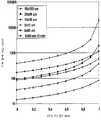
도 1은 피처 크기 대 기포 용해(bubble dissolution)의 그래프를 도시한다.
도 2는 용해된 가스압력 대 기포 용해 시간의 그래프를 도시한다.
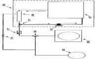
도 3은 프리-웨팅 장치의 일 실시예의 도식적 배치이다.
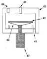
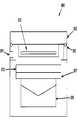
도 4는 프리-웨팅 챔버의 실시예를 도시한다.
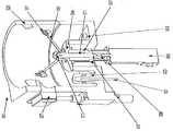
도 5는 프리-웨팅 챔버의 실시예의 등각도이다.
도 6은 응축 프리-웨팅 공정을 위해 구성된 프리-웨팅 챔버의 실시예를 도시한다.
도 7은 잠김(immersion) 프리-웨팅 공정을 위해 구성된 프리-웨팅 챔버의 실시예를 도시한다.
도 8은 잠김 프리-웨팅 공정을 위해 구성된 프리-웨팅 챔버의 또 다른 실시예를 도시한다.
도 9는 프리-웨팅 공정이 도금 셀에서 수행되는 장치의 실시예를 도시한다.
도 10은 전기-도금 시스템의 실시예를 도시한다.
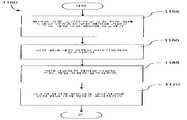
도 11a 및 11b는 프리-웨팅 공정의 실시예에 대한 흐름도이다.
도 12는 웨이퍼 기판 위에 금속층을 전기-도금하기 위한 전기-도금 공정의 실시예에 대한 흐름도이다.
도 13은 프리-웨팅 유체가 충전된 피처를 갖는 웨이퍼 기판을 도시한다.Figure 1 shows a graph of feature size versus bubble dissolution.
Figure 2 shows a graph of dissolved gas pressure versus bubble dissolution time.
3 is a schematic representation of one embodiment of a pre-wetting apparatus.
Figure 4 shows an embodiment of a pre-wetting chamber.
5 is an isometric view of an embodiment of a pre-wetting chamber.
Figure 6 illustrates an embodiment of a pre-wetting chamber configured for a condensing pre-wetting process.
Figure 7 illustrates an embodiment of a pre-wetting chamber configured for immersion pre-wetting processes.
Figure 8 illustrates another embodiment of a pre-wetting chamber configured for a locked pre-wetting process.
Figure 9 illustrates an embodiment of an apparatus in which a pre-wetting process is performed in a plating cell.
Figure 10 shows an embodiment of an electro-plating system.
11A and 11B are flow charts of an embodiment of a pre-wetting process.
12 is a flow chart of an embodiment of an electro-plating process for electro-plating a metal layer on a wafer substrate.
Figure 13 shows a wafer substrate having features filled with pre-wetting fluid.
구체적 실시예에 대한 참조가 이루어질 것이다. 구체적 실시예의 예시가 첨부 도면에 도시된다. 본 발명이 이러한 구체적 실시예와 관련해 기술될 것이나, 이러한 실시예에 본 발명이 제한되는 것이 아님이 이해될 것이다. 오히려, 대안적 형태, 수정 형태, 및 등가물이, 첨부된 청구항에 의해 정의되는 바와 같은 본 발명의 사상과 범위 내에 포함될 수 있도록 의도되었다. 이하의 설명에서, 본 발명에 대한 완전한 이해를 위하여 수많은 세부 사항이 설명된다. 본 발명은 이러한 세부 사항 중 일부 또는 전부 없이 실시될 수도 있다. 그 밖의 다른 경우에서, 본 발명을 불필요하게 불명료하게 만들지 않도록, 공지된 프로세스 동작은 자세히 설명되지 않았다.Reference will now be made to specific embodiments. Examples of specific embodiments are shown in the accompanying drawings. While the invention will be described in connection with such specific embodiments, it will be understood that the invention is not limited to these embodiments. Rather, alternative forms, modifications, and equivalents are intended to be included within the spirit and scope of the present invention as defined by the appended claims. In the following description, numerous details are set forth in order to provide a thorough understanding of the present invention. The present invention may be practiced without some or all of these details. In other instances, well known process operations have not been described in detail so as not to unnecessarily obscure the present invention.
웨이퍼 도입, 도금 중 웨이퍼 처리, 및 프리-웨팅 유체 조성물의 조건을 수정하기 위하여, 웨이퍼 프리-웨팅을 위한 장치 설계 및 방법이 본원에 개시된다. 본원에 제공된 실시예에 따른 프리-웨팅 공정이 전기-도금 챔버에서 수행될 수 있고, 또는 프리-웨팅 장소와 전기-도금 장소를 포함하는 모듈의 별개의 프리-웨팅 장소에서 수행될 수 있다. 일부 실시예에서, 프리-웨팅 공정과 전기-도금 공정이 별개의 장치에서 수행된다.Apparatus designs and methods for wafer pre-wetting are disclosed herein to modify the conditions of wafer introduction, plating during plating, and pre-wetting fluid composition. The pre-wetting process according to embodiments provided herein may be performed in an electro-plating chamber, or may be performed in a separate pre-wetting location of the module including the pre-wetting site and the electroplating site. In some embodiments, the pre-wetting process and the electroplating process are performed in separate devices.
기판은 통상적으로 반도체 웨이퍼이며, 이러한 반도체 웨이퍼는 그 위에 존재하는 전도성 물질층(가령, 구리 또는 구리 합금을 포함하는 시드 층)을 가진다. 전기-도금 동안, 전도성 층으로의 전기적 연결이 이루어지고, 웨이퍼 표면이 음으로 바이어스됨으로써, 캐소드의 역할을 할 수 있다. 웨이퍼는 금속 염(가령, 황산구리(copper sulfate), 구리 알킬술폰산염(copper alkylsulfonate), 또는 염의 혼합물)을 포함하는 도금 용액과 접촉하며, 상기 금속 염이 웨이퍼 캐소드에서 환원됨으로써 웨이퍼 위에 금속이 증착될 수 있다. 많은 실시예에서, 기판은 하나 이상의 오목한 피처(가령, 비아 및/또는 트렌치)를 포함하고, 이러한 오목한 피처는 전기-도금 공정에 의해 충전될 필요가 있다. 또한, 금속 염에 더하여 도금 용액은 산(acid)을 포함할 수도 있고, 통상적으로는, 기판의 다양한 표면상의 전착 속도(electrodeposition)를 조절하는데 이용되는 할로겐화물(가령, 염화물, 브롬화물 등), 촉진제, 레벨러(leveler), 및 억제제와 같은 하나 이상의 첨가물을 포함한다.The substrate is typically a semiconductor wafer, which has a layer of a conductive material (e.g., a seed layer comprising copper or a copper alloy) present thereon. During electroplating, an electrical connection to the conductive layer is made and the wafer surface is negatively biased, thereby serving as a cathode. The wafer is contacted with a plating solution comprising a metal salt (such as copper sulfate, copper alkylsulfonate, or a salt), and the metal salt is reduced at the wafer cathode to deposit a metal on the wafer . In many embodiments, the substrate includes one or more concave features (e.g., vias and / or trenches), and such concave features need to be filled by an electroplating process. Further, in addition to the metal salt, the plating solution may include an acid, and typically includes a halide (e.g., chloride, bromide, etc.) used to control the electrodeposition on the various surfaces of the substrate, Enhancers, accelerators, levelers, and inhibitors.
개시된 공정 및 관련 장치는, 일반적으로 새로 나타난 관통 실리콘 비아(TSV) 전기-충전 구조에서 발견될 수 있는 것과 같은 더 넓은 (가령, 통상적으로 5μm보다 큰), 그리고 더 깊은 (가령, 통상적으로 10μm보다 큰) 다마신 구조(비아)를 전기-충전(electrofilling)하는데 특히 이용되고 필요할 수 있다. 관통 실리콘 비아 구조에 대해 2008년 8월 18일에 출원된 미국 특허 출원 제12/193,644호에 추가로 기술되어 있으며, 상기 미국 특허 출원은 본원에서 참조로서 포함된다. 표면 위에 또는 피처 내에 트랩되거나 존재하는 가스 기포가, 비전도성 가스로 피처 표면을 차단함으로써 또는 전류의 자유 통과에 대한 방해물을 형성함으로써 필드 및 피처 도금 공정을 방해할 것이다. 개시된 공정 및 관련 장치 설계에 의해, 무공동(void-free) 구리 전기-충전(electrofilling)이 가능하다.The disclosed processes and associated devices can be fabricated using a wider (e.g., typically greater than 5 袖 m), and deeper (such as typically greater than 10 袖 m Lt; RTI ID = 0.0 > (e. G., Large) damascene structures (vias). Is described further in U.S. Patent Application No. 12 / 193,644, filed on August 18, 2008, for a perforated silicon via structure, which is incorporated herein by reference. Gas bubbles trapped or present on or in the surface will interfere with the field and feature plating process by blocking the surface of the feature with a non-conductive gas or by forming an obstruction to free passage of current. By the disclosed process and associated device design, void-free copper electrofilling is possible.
TSV 인터커넥션의 전기-도금 및 전기-충전에 있어서 다수의 도전 과제가 존재한다. 여기에는, 매우 넓거나 깊은 구조로 인한 긴 도금 시간, 그리고 도금 전해질 용액과의 시드 층 부식 반응 및 PVD-증착된 시드 층에 의한 하부 측벽의 불충분한 커버리지로 인한 측벽 공동(void)의 형성이 포함된다. 더욱이, 모든 오목한 피처의 내부가 액체로 충전되고 이러한 피처 내부에 도금을 방해하는 트랩된 가스가 존재하지 않음을 보장하는 것이 중요하다. 또한, 피처의 바닥에서 선택적으로 도금 저항성(plating resistance)을 제거하면서, 강한 벽 및 필드 도금 성장-억제를 동시에 유지하는 것이 유리하다.There are a number of challenges in electro-plating and electro-charging of TSV interconnection. This includes long plating times due to very wide or deep structures, and the formation of sidewall voids due to the seed layer corrosion reaction with the plating electrolyte solution and the insufficient coverage of the bottom sidewalls by the PVD-deposited seed layer do. Moreover, it is important to ensure that the interior of all concave features is filled with liquid and that there is no trapped gas inside the features that interferes with plating. It is also advantageous to simultaneously maintain strong wall and field plating growth-inhibition while selectively removing plating resistance at the bottom of the feature.
본원에 기술된 프리-웨팅 장치 설계 및 방법은 일반적으로 금속(특히, 구리)의 전기-도금(캐소딕 공정)과 관련하여 설명된다. 그러나, 본원에 기술된 프리-웨팅 장치 설계 및 방법은 일반적으로 모든 전기 분해 공정(가령, 모두 애노딕 공정인 전기-에칭 및 전해-연마 공정)에도 적용될 수 있다.The pre-wetting device designs and methods described herein are generally described in the context of electro-plating (cathodic processing) of metals, particularly copper. However, the pre-wetting device designs and methods described herein are generally applicable to all electrolytic processes (e.g., electro-etching and electrolytic-polishing processes, both of which are anodic processes).
도금 공정에 필요한, 액체로 충전된 무-기포(bubble-free) 오목한 피처를 형성하는 방법이 기술된다. 더욱이, 시드 층 부식을 최소화하는 동시에 도금 속도를 증가시키는 프리-웨팅 유체의 조성물이 기술된다.A method for forming a liquid filled bubble-free concave feature, which is required for the plating process, is described. Furthermore, compositions of pre-wetting fluids are disclosed that increase plating rates while minimizing seed layer corrosion.
도입Introduction
액체와의 기포 계면에서 용해된 가스의 농도는 헨리의 법칙에 의한 내부 기포압과 관련되며, 헨리의 법칙 중 한 형태가 다음과 같이 표현될 수 있다: The concentration of dissolved gas at the air interface with the liquid is related to the internal bubble pressure by Henry's law, and one form of Henry's law can be expressed as:
Ci =xiHiPi (1)Ci = xi Hi Pi (1)
여기서, 아래 첨자 i는 기포의 "내부"를 가리키고, Ci는 기포 계면에서 액체상(liquid phase)으로 용해된 가스 분자 성분의 농도(가령, moles/l 각각에서 질소, 산소 등)이며, xi는 기포의 내부에서 가스상(gas phase) 그 자체로 있는 분자 성분의 몰분율이고, Hi는 헨리의 법칙 상수이며, Pi는 기포 내부의 압력이다.Here, the subscript i refers to the "inside" of the bubble, Ci is a liquid phase (liquid phase) the concentration (for example, moles / l of nitrogen in each, oxygen, etc.) of gas molecular components soluble in the bubble surface, xi Is the mole fraction of the molecular component in the gas phase itself within the bubble, Hi is the Henry's law constant, and Pi is the pressure inside the bubble.
위 식은 가스의 혼합물에서 가스의 분자 성분 각각에 대하여 표현될 수 있다(예를 들어, 산소에 대하여 하나, 질소에 대하여 하나 등). 벌크 용액(bulk solution)에서 용해된 가스의 농도에 대한 유사한 식이 존재하며, 여기서 아래 첨자 b는, 예를 들어 벌크에서의 화학종(species)의 농도(Cb)와 평형을 이룰 가스상(gas phase) 압력을 나타내는 Pb와 동일한 P를 갖는 용액 "벌크"를 표시하기 위해 사용된다. 2D 및 3D 분산 효과(Dispersion Effect)를 무시하고, 기포 가스상 내부로부터 기포/액체 표면까지의 가스 분자의 확산 속도가 제한되지 않는다고 가정함으로써(이로써, 기포 계면에서 용해된 가스와 기포 안쪽 가스의 농도 사이의 평형 조건이 유지됨), 피처 내부에 트랩된 기포로부터 가스 용해의 속도에 대한 유용한 근사치가 획득될 수 있고, 이러한 속도 근사치가 다음과 같이 표현된다:The above equation can be expressed for each molecular component of gas in a mixture of gases (for example, one for oxygen, one for nitrogen, etc.). There is a similar equation for the concentration of dissolved gas in a bulk solution, where the subscript b is a gas phase which equilibrates with the concentration (Cb ) of the species in the bulk, e. G. ) is used to indicate a solution "bulk" having the same P and Pb represents the pressure. By assuming that the diffusion rate of the gas molecules from the inside of the bubble gas phase to the bubble / liquid surface is not limited (by ignoring the 2D and 3D dispersion effect), and thus the concentration between the gas dissolved in the bubble interface and the gas inside the bubble , A useful approximation of the rate of gas dissolution from the trapped bubbles inside the feature can be obtained, and this rate approximation is expressed as: < RTI ID = 0.0 >
R= dV/dt= DH(xiPi - xbPb) / h(2)R = dV / dt = DH ( x i P i - x b P b) / h (2)
여기서, V는 기포 가스 부피이고, t는 시간이며, D는 용액에서 가스의 확산 계수이고, h는 트랩된 기포의 상부에서부터, 상부 웨이퍼 평면 위의 δ거리에 위치하는 경계층 두께의 에지까지의 거리이며, 아래 첨자 b는 확산 경계층 계면에서 용액의 벌크에서의 조건에 대응한다. 고정된 온도(일정한 헨리의 법칙 상수 및 확산 계수)에서의 주어진 화학 시스템에 있어서, 두 인자: 즉, 1) 큰 농도차/추진력(driving force) (xiP1 - xbPb); 그리고 2) 짧은 확산 거리(h)가 비교적 빠른 기포 용해를 가져올 수 있다.Where D is the diffusion coefficient of the gas in solution, h is the distance from the top of the trapped bubble to the edge of the thickness of the boundary layer located at the delta distance above the upper wafer plane, V is the volume of the bubble gas, t is the time, And the subscript b corresponds to the condition at the bulk of the solution at the diffusion boundary layer interface. For a given chemical system at a fixed temperature (constant Henry's law constant and diffusion coefficient), two factors: 1) a large concentration difference / driving force (xi P1 - xb Pb ); And 2) a short diffusion distance (h) can lead to relatively fast bubble melting.
추진력 항 H(xiP1 - xbPb)의 값이 0인 경우, 용해율이 0이다. 일반적으로 상기 항은 매우 작다. 기포 내의 가스가 프리-웨팅 공정 전 웨이퍼의 비아 내부의 공기로부터 통상적으로 유래되고, 액체가 프리-웨팅 공정 전 통상적으로 상기 공기와 동일한 공기로 포화되기 때문에, 처음에 기포 계면에서의 몰분율과 벌크 용액에서의 몰분율은 공기의 몰분율과 같을 것이다(예를 들어, 기포와 벌크 용액 모두에서, 산소에 대하여 x=0.21). 따라서, 이러한 상황에 있어서 그리고 일반적으로(즉, 기포 용해를 향상시키기 위하여 그 밖의 다른 수단이 이용되지 않는 한), 추진력은 주로 기포 외부 대 기포 내의 자연적인 모세관 압력차이이며, 이러한 모세관 압력차이가 기포 용해를 야기한다.If the value of the propulsive force H (xi P1 - xb Pb ) is 0, the dissolution rate is zero. In general, the term is very small. Since gas in the bubbles is typically derived from the air inside the vias of the wafer prior to the pre-wetting process and the liquid is saturated with the same air as the air typically before the pre-wetting process, Will be equal to the mole fraction of air (for example, x = 0.21 for oxygen, in both bubble and bulk solutions). Thus, in this situation and generally (unless other means are used to enhance bubble dissolution), the propulsion is primarily a natural capillary pressure difference within the bubble outgas, It causes dissolution.
강한 내부 모세관 힘으로 인해, 작은 다마신 피처(가령, 비아) 내에 있는 트랩된 가스가 매우 큰 내부 압력을 나타낼 수 있다. 총 내부 모세관 압력은 접촉각과 표면 장력에 비례하고 기포의 곡률의 반경에 반비례한다.Due to the strong internal capillary forces, the trapped gas in the small damascene features (e.g., vias) can exhibit very large internal pressures. Total internal capillary pressure is proportional to the contact angle and surface tension and is inversely proportional to the radius of curvature of the bubble.
Pi = Pext + σcosθ/ r(3)Pi = Pext +? Cos? / R (3)
여기서, Pi는 기포 내의 총 내부 압력이고, Pext는 유체의 외부 압력(통상적으로 약 1 기압)이며, σ는 액체/가스 표면 장력이고, θ는 고체/액체/가스 접촉각이며, r은 곡률 반경이다. 곡률 반경(r)은 피처 폭과 사실상 다르지 않을 수 있고, 따라서 기포의 곡률 반경에 대한 근사치로서 비아의 반경으로 대체할 수 있다. 작은 비아에 있어서, 총 내부 압력(따라서 각각의 구성요소의 부분압)이 매우 커질 수 있고, 이로써 수 기압(several atmosphere) 이상을 초과할 수 있다. 이로 인해, 이러한 큰 내부 압력이 용액의 벌크에 대하여 비평형 상태를 초래하고, 동일한 압력에서 용액의 벌크에 용해된 가스의 양에 관하여 기포 계면이 상당히 과포화된다(즉, 기포의 계면에서 용해된 가스의 양이 액체에서의 가스 용해도를 초과함). 이는, 빠른 기포 용해를 위한 조건 중 하나를 만족시킨다. 작은 비아에 있어서, 짧은 확산 거리 "h" 역시 빠른 용해 속도에 도움이 된다.Where Pi is the total internal pressure in the bubble, Pext is the external pressure of the fluid (typically about 1 atmosphere), σ is the liquid / gas surface tension, θ is the solid / liquid / gas contact angle, It is a radius. The radius of curvature r may not be substantially different from the feature width and may thus be replaced by a radius of the via as an approximation to the radius of curvature of the bubble. For small vias, the total internal pressure (and thus the partial pressure of each component) can be very large, thereby exceeding more than several atmospheres. This causes such a large internal pressure to result in a non-equilibrium state with respect to the bulk of the solution, and the bubble interface is considerably supersaturated with respect to the amount of gas dissolved in the bulk of the solution at the same pressure (i. E. Is greater than the solubility of the gas in the liquid). This satisfies one of the conditions for fast bubble dissolution. For small vias, the short diffusion distance "h" also aids the fast dissolution rate.
이와 반대로, 더 큰 반경의 기포를 갖는 큰 비아는 작은 초과 내부 압력과 훨씬 긴 확산 거리를 가진다. 대기압에서 처음에 50%가 가스로 충전된 비아에 있어서 3:1 종횡비(깊이-대-폭)를 갖는 비아에 대한 비아 깊이의 함수로서, 다양한 조건(즉, 용해된 가스의 부분압, 웨이퍼의 회전율)에 있어서 완전한 기포 용해를 위한 시간의 계산/모델링이 도 1에 도시된다. 도 1에 도시된 모든 공정에 있어서, 비아의 σ = 60 dyne/cm(예를 들어, 물에 대한 값), D = 1.9E-5 cm2/sec(예를 들어, 물 내의 공기에 대한 값), T=20℃, 그리고 Vi = 50%이다.Conversely, large vias with larger radius bubbles have a small excess internal pressure and a much longer diffusion distance. As a function of via depth for vias with a 3: 1 aspect ratio (depth-to-width) for vias filled initially with 50% gas at atmospheric pressure, various conditions (i.e. partial pressure of dissolved gas, / RTI > is calculated / modeled for complete bubble dissolution is shown in FIG. For all of the processes shown in Figure 1, the σ of the vias = 60 dyne / cm (for example, for water), D = 1.9E-5 cm2 / sec ), T = 20 [deg.] C, and Vi = 50%.
Vi는 1기압 압력 하에서의 기포의 초기 부피이다(즉, 이러한 도표를 생성하기 위하여 각각의 비아의 50%만이 기포로 충전됨). Pext= 0.2인 경우에 있어서, 유체에 대한 압력은 여전히 1기압이나, 액체의 벌크에 용해된 가스의 부분압은 단지 0.2 기압의 가스 압력과 평형을 이루는 압력과 동일하다. 예를 들어,탈가스된 유체 위의 가스의 압력이 1 기압인 동안 0.2 기압의 압력을 갖는 상기 유체가 표면을 흘러 넘치게 함으로써 트랩된 기포를 형성하는 것에 의해 위와 같은 조건이 성취될 수 있다. Pext= 3인 경우에 있어서, 액체에서 용해된 가스의 양이 1 기압의 압력과 평형을 이루는 압력과 동일하나, 액체 및 기포에 대한 압력은 3 기압 압력과 동일하다. 예를 들어, 대기-포화된(atmospheric-saturated) 액체가 표면을 흘러 넘치게 하고, 그 후 3 기압의 비아/액체/웨이퍼 위에 외부 압력을 가함으로써 트랩된 기포를 형성하는 것에 의해 위와 같은 조건이 성취될 수 있다.Vi is the initial volume of bubbles under 1 atmospheric pressure (i. E., Only 50% of each vial is filled with bubbles to produce this plot). In the case of Pext = 0.2, the pressure on the fluid is still equal to 1 atm, but the partial pressure of the gas dissolved in the bulk of the liquid is equal to the pressure equilibrating with a gas pressure of only 0.2 atm. For example, the above conditions can be achieved by forming trapped bubbles by allowing the fluid having a pressure of 0.2 atmospheres to overflow the surface while the pressure of the gas on the degassed fluid is 1 atm. In the case of Pext = 3, the amount of gas dissolved in the liquid equals the pressure which equilibrates with the pressure of 1 atm, but the pressure for liquid and air bubbles is equal to 3 atm. For example, the above conditions can be achieved by causing the atmospheric-saturated liquid to flood the surface and then trapped bubbles by applying external pressure to the 3-atmosphere via / liquid / wafer. .
그래프 A 및 F(탈가스되지 않은 프리-웨팅 유체, 가스의 양은 1 기압 공기와 평형을 이루는 압력과 동일함)를 그래프 B 및 C(0.2 기압과 동일한 부분압까지 탈가스된 프리-웨팅 유체)를 비교하면, 탈가스된 용액의 경우가 더 짧은 기포 용해 시간을 가진다. 그래프 F와 C를 비교하면 유사하지만, 웨이퍼가 더 느린 속도(A와 B에서 90 rpm 대 12 rpm)로 회전하였기 때문에 경계층 두께와 용해 시간이 더 크다.Graphs B and C (pre-wetting fluid degassed to a partial pressure equal to 0.2 atmospheres) are shown in graphs A and F (the amount of ungashed pre-wetting fluid, gas equals pressure equilibrating with 1 atm air) By comparison, the degassed solution has a shorter bubble dissolution time. Comparison of graphs F and C is similar, but the boundary layer thickness and dissolution time are greater because the wafer rotated at slower speeds (90 rpm versus 12 rpm at A and B).
도 1의 그래프 A 및 F는, 용액이 공기로 포화된 비아 내부에서 기포의 용해 시간이, 0.2μm의 크기 대 50μm의 크기 사이에서 5 자릿수 이상(105 이상) 변한다는 것을 보여준다. 작은 서브 마이크론(submicron) 피처에서는 기포가 불안정하여 빠르게 용해되지만, 더 큰 피처에서는 기포가 매우 긴 시간 동안 존속될 것이다. 예를 들어, 가스로 완전히 충전된 1μm의 직경 및 4μm의 깊이를 갖는 비교적 큰 전공정(front end of the line) 구조로 인해 상기 가스가 4초 내에 완전히 용해될 것이라는 것을 산출 결과가 보여준다. 이와 반대로, 1μm 깊이의 0.25μm 피처는 매우 불안정해서 0.4초 내에 용해될 것이고, 더 작은 구조에서는 본질적으로 즉시 용해될 것이다. 그러나, 큰 TSV 스케일 구조에서는 바람직한 인자(즉, 높은 내부 압력과 짧은 확산 거리) 모두가 존재하지 않는다. 이와 반대로, 25μm의 폭과 100μm 깊이의 피처에 있어서는 기포를 용해시키기 위하여 2시간 이상이 걸릴 수 있음을 산출 결과가 보여준다. 상기 피처가 그 하부에 오직 10%만이 가스로 충전된 경우라 하더라도, 상기 가스가 제거되기 위하여 여전히 20분 이상이 소요될 것이다.The graphs A and F of Figure 1 show that the dissolution time of the bubbles within the vias in which the solution is saturated with air varies by more than 5 digits (over 105 ) between the size of 0.2 μm and the size of 50 μm. In small submicron features, bubbles are unstable and dissolve quickly, while in larger features bubbles will persist for a very long time. For example, the calculation results show that the gas will be completely dissolved in 4 seconds due to the relatively large front end of the line structure with a diameter of 1 m and a depth of 4 m, which is fully filled with gas. Conversely, a 0.25 μm feature at 1 μm depth will be very unstable and will dissolve within 0.4 seconds, and in a smaller structure it will essentially dissolve immediately. However, in a large TSV scale structure, there are no desirable factors (i.e., high internal pressure and short diffusion distance). On the contrary, the calculation results show that it takes more than 2 hours to dissolve the bubbles in the width of 25 μm and the depth of 100 μm. Even if the feature is filled with only 10% gas at the bottom, it will still take 20 minutes or more for the gas to be removed.
프리-웨팅 유체로부터 가스를 제거함으로써 트랩된 기포를 용해시키는 시간이 감소한다. 이 경우, 용액으로부터 가스를 제거함으로써(예를 들어, 부분적인 진공 하의 탈가스 유닛에서 프리-웨팅 유체에 노출된 가스의 부분압을 감소시킴으로써) 추진력의 오른쪽 항(식 2에서 xbPb)이 작아진다(즉, 탈가스 유닛의 가스 측에서 산출물의 크기를 줄임으로써, 가스가 액체로부터 제거된다). (유의한 모세관 압력이 존재할 때) 트랩된 기포 내의 가스가 대략 1 기압 이상의 압력으로 있다. 기포 계면에서, 가스의 농도가 위와 동일한 1 기압 이상의 압력과 거의 평형을 이루는 농도에 있을 것이지만, 용액에서는, 탈가스 동작으로 인해 전체적인 농도는 훨씬 낮은 농도로 있다. 이로써 용액에서 유의한 농도 추진력과 가스의 불포화(sub-saturation) 정도가 형성되어(화학적 "수용력"), 기포를 빠르게 용해시킬 수 있다.The time to dissolve the trapped bubbles is reduced by removing gas from the pre-wetting fluid. In this case, the right term of the propulsive force (xb Pb in Eq. 2) is obtained by removing the gas from the solution (for example by reducing the partial pressure of the gas exposed to the pre-wetting fluid in a degassing unit under partial vacuum) (I.e., by reducing the size of the product at the gas side of the degassing unit, the gas is removed from the liquid). (When significant capillary pressure is present) the gas in the trapped bubbles is at a pressure of at least 1 atmosphere. At the bubble interface, the concentration of the gas will be at a concentration that is nearly in equilibrium with a pressure equal to or greater than 1 atmospheres, but in solution the overall concentration is much lower due to the degassing operation. This results in a significant concentration of propellant force in the solution and a degree of sub-saturation of the gas (chemical "capacity") which can rapidly dissolve the bubbles.
이러한 절차가 처음에는 매력적인 것으로 나타날 수 있으나, 두 가지 제한이 가해질 수 있다. 첫째, 크고 깊은 비아에 있어서, 가스에 대한 확산 거리가 여전히 유의한 제한 인자일 수 있다. 둘째, 용액 내의 가스의 양이 절대로 0보다 적을 수 없기 때문에, 용해를 위한 추진력의 크기가 대략 HxiP(P=1 기압) 이하로 제한된다. 도 1의 그래프 B 및 C를 그래프 A 및 F와 비교하면, 큰 피처(가령, 50μm)의 용해 속도가 탈가스되지 않은 가스보다 한 자릿수 이상(10 배 이상) 감소하지만, 용해 시간은 일반적으로 용납할 수 없을 정도로 길다(가령, 최소한 5-10분). 1기압의 용해 가스 추진력의 증가량과 비교되는 큰 초과 내부 기포 압력에 의해 공정이 지배를 받기 때문에, 더 작은 피처의 용해 속도는 탈가스된 용액의 이용에 의해 사실상 영향을 받지 않는다.These procedures may initially appear attractive, but two restrictions may apply. First, for large and deep vias, the diffusion distance to the gas may still be a significant limiting factor. Second, since the amount of gas in the solution can never be less than zero, the magnitude of the propelling force for dissolution is limited to about Hxi P (P = 1 atm) or less. Comparing graphs B and C of FIG. 1 with graphs A and F, the dissolution rate of large features (e.g., 50 占 퐉) is reduced by more than one order of magnitude (more than 10 times) It is too long to do (eg, at least 5-10 minutes). Since the process is dominated by a large excess internal bubble pressure compared to an increase in the molten gas propulsion force of one atmosphere, the dissolution rate of the smaller features is virtually unaffected by the use of the degassed solution.
도 2는 (90 rpm 회전수, 60 dyne/cm에서) 다양한 피처 치수에 대한 기포 용해 시간을 보여주며, 여기서, 용해된 가스의 양은 독립적 파라미터이다. 각각의 경우에서, 처음에 기포가 비아 크기의 50%이며, 비록 용해된 부분압이 x 축의 함수로서 변화한다 하더라도, 유체와 기포에 대한 1 기압의 외부 압력이 존재한다. 명확성을 위하여, 도 2에서, 용해된 가스의 농도는 헨리의 법칙과 관련하여, x-축 상의 용해된 가스에 대응한다. 이러한 부분압은, 예를 들어, 접촉 유체를 x-축 파라미터의 정도까지 탈가스함으로써 획득될 것이다. 더 작고 덜 깊은 피처 내의 기포가 더 빠르게 용해되고, 큰 내부 모세관 압력에 의해 속도가 촉진된다. 또다시, 더 작은 피처에 대한 부분압을 감소시킴으로써, 용해 시간 감소에 대하여 적은 상대 효과(relative effect)를 가지게 된다. 더 큰 피처(가령, 50μm x 150μm)에 있어서, 용해된 가스의 부분압을 포화 상태의 30 내지 40% 이하로 감소시킴으로써 이점이 줄어든다. 가장 작고 가장 얕은 피처에서, 용해 시간이 100초를 초과한다. 피처 깊이는 모든 경우에서 유의한 제한 인자인데, 깊은 피처는 긴 용해 시간을 갖는다.Figure 2 shows the bubble melting time for various feature dimensions (at 90 rpm, at 60 dyne / cm), where the amount of dissolved gas is an independent parameter. In each case, initially, the bubble is 50% of the via size, and even though the dissolved partial pressure changes as a function of the x-axis, there is an external pressure of one atmosphere for the fluid and bubbles. For clarity, in FIG. 2, the concentration of the dissolved gas corresponds to dissolved gas on the x-axis in connection with Henry's law. This partial pressure will be obtained, for example, by degassing the contact fluid to an extent of the x-axis parameter. The bubbles in the smaller, less deep features dissolve faster and the velocity is promoted by the larger internal capillary pressure. Again, by reducing the partial pressure on the smaller features, it has a lesser relative effect on dissolution time reduction. For larger features (e.g., 50 [mu] m x 150 [mu] m), the advantage is reduced by reducing the partial pressure of the dissolved gas to 30-40% or less of the saturated state. At the smallest and shallower feature, the dissolution time exceeds 100 seconds. Feature depth is a significant limiting factor in all cases, with deep features having a long dissolution time.
장치Device
일반적으로, 본원에 기술된 장치 설계 및 방법은, 표면과 피처를 유체로 프리-웨팅하기 전에 먼저 피처 내부로부터 가스(주로, 모두 비-응축성 가스)(가령, 질소 및 산소)를 제거함으로써 웨이퍼 기판상의 오목한 피처(가령, 비아) 내에서의 기포의 형성을 막는다. 이를 위하여, 웨이퍼를 고정하고 웨이퍼 표면에서 가스를 제거하기에 적합한 용기(가령, 진공 용기)에 오목한 피처를 갖는 웨이퍼가 배치된다. 이러한 용기 자체에 더하여, 진공 상태가 유지되는 동안 가스를 제거하기 위한 수단(가령, 펌프와 같은 진공 소스에 연결된 라인) 및 표면상에 액체를 증착하기 위한 수단이 요구된다.In general, the device designs and methods described herein provide for the removal of gases (primarily both non-condensable gases) (e.g., nitrogen and oxygen) from the interior of the features prior to pre-wetting the surfaces and features with the fluid Thereby preventing the formation of bubbles in the recessed features (e.g., vias) on the substrate. To this end, a wafer having recessed features in a container (e.g., a vacuum container) suitable for holding the wafer and removing gas from the wafer surface is disposed. In addition to such a container itself, there is a need for means for removing gas (e.g., a line connected to a vacuum source, such as a pump) while the vacuum is maintained, and means for depositing liquid on the surface.
도금 공정의 시작 전 또는 도금 공정의 시작 후 단시간 내에 웨이퍼를 프리-웨팅하기 위한 다양한 장치 설계가 본원에 기술되며, 여기서, 본 발명 장치 설계가 아니라면 표면 안쪽으로 오목한 피처 내에 트랩될 수도 있는 기포와 가스가 트랩되지 않게 된다. 프리-웨팅 장치의 실시예들은 다양한 구성요소를 포함한다. 통상적으로, 프리-웨팅 장치는 액체 혼합 디바이스, 액체 레벨 제어기, 및 센서를 포함하는 프리-웨팅 유체 저장 및 반환 탱크를 포함한다. 일부 실시예에서, 본 발명 장치는 프리-웨팅 유체 탈가스 흐름 루프(flow loop)를 포함한다. 일부 실시예에서, 이러한 탈가스 흐름 루프는 순환식 펌프(circulating pump), 라우팅/전환 밸브, 액체 탈가스 요소, 및 상기 액체 탈가스 요소와 (도구 및 프리-웨팅 챔버 상의 다양한 액체 탈가스 요소를 펌핑(pump-down)하여 진공 상태로 만드는데 이용되는) 시스템 진공 펌프 사이의 연결부를 포함한다. 또한 프리-웨팅 장치는 프리-웨팅 챔버를 포함한다. 일부 실시예에서 프리-웨팅 챔버는 두 곳에 위치된, 챔버에 액세스하기 위한 (개방형/폐쇄형) 진공 웨이퍼 액세스 도어(access door) 또는 리드(lid)와, 조합형 도어/리드와, 액체가 가열되어 그 이후에 상부 벽 또는 도어로부터 웨이퍼 표면으로 액체가 적하(drop)되는 것을 방지하는 스플래시 실드(splash shield)를 포함한다. 일부 실시예에서, 챔버 내부에는 챔버 내에서 웨이퍼를 지지하고 회전시키기 위한 웨이퍼 고정부가 있다. 일부 실시예에서, 챔버는 에어돔(air-dome) 챔버-히터를 포함하고, 상기 챔버-히터는, 만일 다른 경우라면 웨이퍼 및 진공 웨이퍼 액세스 도어 위에 존재하여 잠재적으로 웨이퍼 위로 적하될 수 있는 액체가 챔버의 벽에서 응축되는 것을 방지하기 위해 사용된다. 프리-웨팅 챔버는 통상적으로, 프리-웨팅 유체를 챔버로 주입하여 상기 프리-웨팅 유체가 회전식 웨이퍼의 상부 표면에 다다르도록 하기 위한 주입 포트와, 챔버를 진공 상태로 되게 하거나 진공 상태를 해소하기 위한 주입 라인 및 챔버 포트를 포함하며, 상기 주입 라인은 입자 여과 디바이스를 포함하고, 상기 주입 포트는 유입 가스 흐름을 분산시시켜 챔버 유동 난류(flow turbulence)를 최소화하도록 구성된 흐름 확산기(flow diffuser)를 포함한다. 일부 실시예에서, 챔버는 빈 상태/준비 상태 및 범람 상태/초과 상태를 모니터링하기 위한 액체 레벨 센서를 포함한다. 프리-웨팅 챔버는 또한, 챔버로부터 액체를 제거하여 배출된 액체가 저장 탱크로 다시 향하도록 하기 위한 배출구를 포함한다.Various device designs are described herein for pre-wetting wafers before the start of the plating process or shortly after the start of the plating process, where bubbles and gases, which may otherwise be trapped within recessed features in the surface, Is not trapped. Embodiments of the pre-wetting apparatus include various components. Typically, the pre-wetting apparatus includes a pre-wetting fluid storage and return tank comprising a liquid mixing device, a liquid level controller, and a sensor. In some embodiments, the apparatus includes a pre-wetting fluid degassing flow loop. In some embodiments, such a degassing flow loop includes a circulating pump, a routing / switching valve, a liquid degassing element, and a plurality of liquid degassing elements (such as tools and various liquid degassing elements on the pre- And a connection between the system vacuum pump (which is used to pump-down and vacuum). The pre-wetting apparatus also includes a pre-wetting chamber. In some embodiments, the pre-wetting chamber comprises a vacuum wafer access door or lid (open / closed) for accessing the chamber, located in two places, a combined door / lead, And a splash shield to prevent liquid from dropping thereafter from the top wall or door to the wafer surface. In some embodiments, the interior of the chamber has a wafer securing portion for supporting and rotating the wafer within the chamber. In some embodiments, the chamber includes an air-dome chamber-heater, which, if otherwise, is present on the wafer and the vacuum wafer access door, and potentially liquid that can be dropped onto the wafer It is used to prevent condensation on the wall of the chamber. The pre-wetting chamber typically comprises an inlet port for injecting a pre-wetting fluid into the chamber to cause the pre-wetting fluid to reach the upper surface of the rotating wafer, and an inlet port for evacuating the chamber, Wherein the injection line comprises a particle filtering device and the injection port comprises a flow diffuser configured to disperse the incoming gas flow to minimize chamber flow turbulence, . In some embodiments, the chamber includes a liquid level sensor for monitoring an empty / ready state and an overflow state / overflow condition. The pre-wetting chamber also includes an outlet for removing liquid from the chamber and directing the discharged liquid back to the storage tank.
본원에 기술된 실시예들은, (1) 웨이퍼 위에서 그리고 비아 내부로부터 대기의 비응축성 가스 모두를 실질적으로 제거하고, 그 후 상기 웨이퍼를 프리-웨팅 유체로 프리-웨팅함으로써 프리-웨팅 동안 비아에 가스가 트랩되는 것을 전적으로 회피하고; 및/또는 (2) 기포 계면에서 크게 과포화된 상태를 형성하는 것에 의해, 큰 외부 압력을 유체에 가하고 이로써 기포가 유체에 용해되도록 하여 기포가 용해되는 속도를 유의하게 증가시킴으로써, 트랩된 기포, 특히 웨이퍼 내의 큰 비아 또는 트랜치에 형성될 수 있는 기포의 유해 효과를 극복한다. 이러한 사전 처리 및 사전 도금 조치에 더하여, 일부 실시예에서는, 탈가스된 상태로 유지되는 도금 용액에서 도금이 수행되고, 그 밖의 다른 실시예에서는, 웨이퍼 표면에 노출되기 직전의 라인에서 도금 용액이 탈가스된다.Embodiments described herein can be used to (1) substantially remove all non-condensable gases in the atmosphere from above the wafer and from within the vias, and then pre-wetting the wafer with the pre- ≪ / RTI > And / or (2) significantly increasing the rate at which the bubbles are dissolved by applying a large external pressure to the fluid thereby causing the bubbles to dissolve in the fluid, by forming a largely supersaturated state at the air interface Overcomes the deleterious effects of bubbles that can form in the vias or trenches in the wafer. In addition to these pretreatment and pre-plating measures, in some embodiments, plating is performed in a plating solution that is maintained in a degassed state, and in other embodiments, a plating solution is removed in a line immediately before being exposed to the wafer surface Gas.
일부 실시예에서, 전기-도금 셀 내에서 프리-웨팅을 수행하는 것이 가능하고, 여기서 프리-웨팅 유체는 도금 용액과 동일한 조성을 가진다. 그러나, 도금 공정과 진공 공정 조합의 하드웨어 복잡성을 포함한 다양한 이유에서, 진공 피처-재충전된 프리-웨팅을 포함하는) 프리-웨팅이 도금 셀과는 다른 셀, 서브-셀, 또는 모듈에서 종종 수행된다. 진공 하의 프리-웨팅이 도금 용액에서보다는 도금 셀의 명백히 다른 영역에서 또는 도금 셀과 명백히 분리된 모듈에서 수행될 때, 프리-웨팅 유체의 조성물이 선택될 수 있다. 프리-웨팅 유체는 이후에 웨이퍼를 도금하는데 사용되는 것과 같은 또는 매우 유사한 조성물을 가질 수 있다. 프리-웨팅 유체는 도금욕(plating bath)의 요소 모두(가령, 도금 용액에서와 동일한 또는 매우 유사한 농도에서, 동일한 용매, 용해된 동일한 금속 이온, 산, 양이온, 첨가물, 및 할로겐화물)를 포함할 수 있다. 이러한 프리-웨팅 유체가 일부 실시예에서 쓰일 수 있다. 대안적으로, 그 밖의 다른 실시예에서, 도금 용액과는 아주 다른 프리-웨팅 유체가 이용될 수도 있다. 예를 들어, 일부 실시예에서, 1) 물, 2) 도금 용액보다 실질적으로 더 큰 금속 이온 농도를 갖는 유체, 3) 더 낮고 서로 다른 할로겐화물 조합 또는 전혀 용해되지 않은 할로겐화물을 갖는 유체, 4) 실질적으로 도금 첨가제 중 하나, 소수, 또는 모든 도금 첨가제가 없는 유체, 또는 5) 수용성(water-miscible) 용매의 프리-웨팅 유체가 프리-웨팅 유체로서 이용될 수 있다. 이러한 프리-웨팅 유체는 본원에서 추가로 설명된다.In some embodiments, it is possible to perform pre-wetting in the electro-plating cell, wherein the pre-wetting fluid has the same composition as the plating solution. However, for various reasons, including hardware complexity of plating and vacuum process combinations, pre-wetting (including vacuum feature-refilled pre-wetting) is often performed in a different cell, sub-cell, or module than the plating cell . When the pre-wetting under vacuum is performed in a distinctly different area of the plating cell than in the plating solution or in a module that is clearly separated from the plating cell, a composition of the pre-wetting fluid can be selected. The pre-wetting fluid may have a composition that is the same as or very similar to that used to subsequently coat the wafer. The pre-wetting fluid comprises all of the elements of the plating bath (e.g., the same solvent, dissolved same metal ion, acid, cation, additive, and halide at the same or very similar concentration as in the plating solution) . Such pre-wetting fluid may be used in some embodiments. Alternatively, in other embodiments, a substantially different pre-wetting fluid than the plating solution may be used. For example, in some embodiments, 1) water, 2) a fluid having a metal ion concentration substantially greater than the plating solution, 3) a fluid having lower and different halide combinations or halides that are not dissolved at all, 4 ) One of the plating additives, a minority, or a fluid free of all plating additives, or 5) a pre-wetting fluid of a water-miscible solvent may be used as the pre-wetting fluid. Such pre-wetting fluids are further described herein.
a) 도금 시작 전 웨이퍼 기판 위의 금속층 부식 가능성; b) 도금 공정의 억제 가능성(즉, 피처 금속-충전 공정의 감속 또는 상기 공정의 완전한 억제); c) 후속 프리-웨팅 유체 재이용을 위한 프리-웨팅 유체의 손실 가능성; 그리고 d) 시간에 따라 도금욕 내의 다양한 중요 화학종 농도의 (추가, 희석, 또는 농축에 의한) 변경 가능성을 포함하는 프리-웨팅 유체 조성물을 선택할 때 다수의 인자가 고려되어야 한다. 위 변경 공정에서, 도금욕 내의 금속 이온 농도, 할로겐화물 농도, 유기 첨가제 등을 변경할 수 있다. 이러한 효과는 꽤 실질적일 수 있다. 더욱이, 도금욕과는 다른 조성물의 프리-웨팅 유체를 이용할 때, 도금 용액에 부가될 반출된 프리-웨팅 유체의 초과량을 제거 및 회복하는 적절한 수단을 활성화함이 없이 동일한 모듈에서 프리-웨팅 공정을 수행함으로써, 시간에 따른 도금 용액 수정을 위한 완화, 모니터링 및/또는 정정 수단을 일반적으로 요구할 것이다. 한편, 상기 유체의 분리 및 회복을 가능하게 하는 도금 셀의 별개의 처리 장소, 모듈, 용기, 또는 서브-용기에서 프리-웨팅 동작이 수행되는 공정 및 하드웨어의 이용이 유리할 수 있는데, 이러한 이용에 의해 위와 같은 문제 거리를 피할 수 있기 때문이다. 이를 배경으로 하여, 그리고 실시예의 핵심 개념에 대한 설명을 간소화하기 위하여, 별개의 프리-웨팅 "장소" 및 별개의 "도금 장소"의 맥락에서 여러 실시예가 이하에 기술되며, 웨이퍼가 전자의 "장소"에서부터 후자의 "장소"까지 이동된다. 그러나, 일부 상황에서는 바람직할 수 있지만(예를 들어, 동일하지 않은 액체의 혼합을 피하기 위하여 또는 그 밖의 다른 이유로), 프리-웨팅 물질, 일반적인 유체, 및 도금 처리 순서의 특정적 선택과 관련된 실시예의 양상이 제한적으로 의도되지는 않는다.a) possible corrosion of the metal layer on the wafer substrate prior to the start of plating; b) possible inhibition of the plating process (i. e., slowing down of the feature metal-fill process or complete inhibition of the process); c) possible loss of pre-wetting fluid for subsequent pre-wetting fluid reuse; And d) the ability to vary (by addition, dilution, or concentration) of various critical chemical species concentrations in the plating bath over time. A number of factors must be considered when selecting the pre-wetting fluid composition. In the above-mentioned changing process, the metal ion concentration in the plating bath, the halide concentration, the organic additive, and the like can be changed. This effect can be quite substantial. Furthermore, it would be advantageous to employ a pre-wetting process in the same module without activating the appropriate means of removing and recovering the excess of the exported pre-wetting fluid to be added to the plating solution when using a pre-wetting fluid of a composition different from the plating bath Monitoring, and / or correcting means for plating solution solution over time. On the other hand, the use of the process and hardware in which the pre-wetting operation is performed in a separate processing station, module, vessel, or sub-vessel of the plating cell that enables the separation and recovery of the fluid may be advantageous, This problem can be avoided. With this in mind, and in order to simplify the description of the core concept of the embodiment, various embodiments are described below in the context of separate pre-wetting "places" and separate "plating places" Quot; to "place" of the latter. However, although it may be desirable in some situations (e.g., to avoid mixing of unequal liquids or for other reasons), it may be advantageous to use a pre-wetting material, a general fluid, The aspects are not intended to be limiting.
도 3은 프리-웨팅 장치(즉, 챔버(301) 및 관련 하드웨어)의 일 실시예의 도시적 레이아웃을 도시한다. 챔버(301)가 챔버 내의 배출구를 통해, 그리고 3갈래 밸브 연결부(605)를 통해 진공 펌프(303)에 연결된다. 3갈래 밸브의 그 외 다른 측면에, 프리-웨팅 유체 탱크(307), 탈가스 디바이스(309), 및 탈가스 루프 주위로 프리-웨팅 유체를 회전시키는 펌프(311)를 포함하는 탈가스 루프(306)가 있다. 또 다른 실시예에서, 프리-웨팅 주입 라인과 진공 라인이 챔버에서를 제외하고는 연결되지 않으며, 위 라인들은 각자 자신의 밸브를 갖는다(즉, 3갈래 밸브가 아님). 대안적 실시예에서, 챔버는 프리-웨팅 유체가 들어오기 위한 주입구와 진공 펌프와의 연결에 적합한 배출구를 가진다. 유체가 프리-웨팅 유체 탱크(307)와 챔버(301) 사이의 압력 차동에 의해 챔버 내부로 흡입되기 보다는 펌프에 의해 챔버 내부로 유체가 흘러들어가기를 바라는 경우, 펌프(311)의 위치는 탈가스 요소 다음일 수 있다.Figure 3 shows an illustrative layout of one embodiment of the pre-wetting apparatus (i.e., chamber 301 and associated hardware). Chamber 301 is connected to the vacuum pump 303 through an outlet in the chamber and through a three-way valve connection 605. [ On the other side of the three-way valve, a degassing loop (not shown) including a pre-wetting fluid tank 307, a degassing device 309, and a pump 311 rotating the pre- 306). In another embodiment, the pre-wetting injection line and the vacuum line are not connected except in the chamber, and the above lines each have their own valve (i.e. not a three-way valve). In an alternative embodiment, the chamber has an inlet adapted for connection of the inlet with the pre-wetting fluid and an outlet adapted for connection with the vacuum pump. When the fluid is desired to flow into the chamber by the pump rather than being sucked into the chamber by pressure differential between the pre-wetting fluid tank 307 and the chamber 301, Elements can be following.
일부 실시예에서, 진공 펌프(도시되지 않음)를 이용하여 홀딩 탱크(holding tank)에 진공 상태를 가함으로써, 탱크(307)에 담긴 프리-웨팅 유체 내의 영역에서 가스가 제거되며, 이로써 용해되지 않은 가스량이 최소화될 수 있다. 또한, 예를 들어, 유체가 분무기(spray) 내의 순환 루프로부터 챔버로 다시 주입되도록 하거나 분무탑(spray column)을 통해 진공에 노출된 유체의 표면을 증가시킴으로써, 프리-웨팅 유체로부터의 가스의 속도 또는 가스의 제거가 증가될 수 있다. 도 3에 도시된 시스템의 실시예에서, 프리-웨팅 전에 프리-웨팅 유체로부터 하나 이상의 용해되지 않은 가스(가령, O2 및 N2 모두)를 제거하기 위하여 탈가스 디바이스(309)(가령, 일부 실시예에서, 막 접촉 탈가스 장치(membrane contact degasser))를 통해 프리-웨팅 유체가 순환된다. 상업적으로 입수 가능한 탈가스 디바이스의 예시에는 Membrana of Charlotte의 Liquid-CelTM, 미네소타 Chaska의 Entegris로부터의 pHasorTM가 포함된다. 용해되지 않은 가스의 양이 적절한 측정기(가령, 상업용 용해되지 않은 산소 측정기(도시되지 않음)를 이용하여 모니터링될 수 있다. 본원에 기술된 바와 같이, 프리-웨팅 유체를 챔버(31)로 주입하기 전 용해되지 않은 가스를 제거함으로써 프리-웨팅 공정을 개선할 수 있다. 선택 사항으로서, 프리-웨팅 유체를 탈가스한 이후, 탈가스 챔버(309)의 진공 측과 진공 펌프(303) 사이의 밸브(315)가 폐쇄된다(이로써, 초기에 챔버 내의 가스가 탈가스된 프리-웨팅 유체에서 용해되지 않는 것을 방지한다; 일부 실시예에서, 별개의 펌프가 이러한 두 기능을 위해 사용될 수 있다).In some embodiments, by applying a vacuum to the holding tank using a vacuum pump (not shown), the gas is removed in the region within the pre-wetting fluid contained in the tank 307, The amount of gas can be minimized. It is also contemplated that the velocity of the gas from the pre-wetting fluid may be increased by, for example, allowing fluid to be injected back into the chamber from the circulation loop in the spray or by increasing the surface of the fluid exposed to the vacuum through the spray column Or gas removal can be increased. In the embodiment of the system shown in Figure 3, the pre-wetting before pre-wetting fluid one or more non-dissolved gas from the degassing device 309 in order to remove (e.g., O2 and N2 both) (e. G., Some In an embodiment, the pre-wetting fluid is circulated through a membrane contact degasser. Examples of commercially available degassing devices include Liquid-Cel (TM) from Membrane of Charlotte, pHasor (TM) from Entegris, Chaska, Minnesota. The amount of undissolved gas can be monitored using a suitable meter (e.g., a commercial undissolved oxygen meter (not shown).) As described herein, the pre-wetting fluid is injected into the chamber 31 After degassing the pre-wetting fluid, the valve (s) between the vacuum side of the degassing chamber 309 and the vacuum pump 303, (Thereby preventing the gas in the chamber from initially dissolving in the degassed pre-wetting fluid; in some embodiments, a separate pump can be used for these two functions).
도 3와 유사하게 구성된 장치를 이용할 때 존재하는 조건과 다르게, 프리-웨팅 유체를 진공 하의 웨이퍼에 노출시키기 전에 프리-웨팅 유체가 탈가스되지 않은 경우, 상기 유체로부터 용해되지 않은 가스가, 챔버로 주입됨으로써 상기 유체로부터 해방될 수 있다. 이는 비아 내부에 기포의 형성을 초래한다. 특정 모델 또는 이론에 의해 제한되는 것을 원치 않는 경우, 비아 바닥이 음의 곡률 장소이고, 상기 장소가 특히 기포의 핵을 이루기 쉽고 프리-웨팅 유체로부터 가스를 해방시키기 쉽다. 이러한 경우, 프리-웨팅 조건 하에서(가령, 챔버 내의 진공) 프리-웨팅 유체가 가스로 포화되기 때문에, 용해되지 않은 가스를 포함하는 프리-웨팅 유체로부터 기포가 형성될 것이다. 이렇게 형성된 기포가 프리-웨팅 공정 이후에 그곳에 남아있을 수 있고, 이러한 기포는 차례로 그 곳의 도금을 방해할 수 있고 관련 결점을 초래할 수 있다. 따라서, (도 3에 도시된 실시예를 포함하는) 일부 실시예에서, 프리-웨팅 공정에 이용된 프리-웨팅 유체는 탈가스된 프리-웨팅 유체이다. 일부 실시예에서, 탈가스된 프리-웨팅 유체가 도금 용액일 수 있고, 본원에 기술된 프리-웨팅 방법은 도금 챔버 자체와 동일한 챔버에서 수행될 수 있다. 별개의 프리-웨팅 챔버 및 장치가 이용되나 프리-웨팅 유체가 탈가스되지 않은 경우, 간헐적인 신뢰할 수 없는 충전(filling) 결과가 관찰될 수 있다. 예를 들어, (진공 하의 웨이퍼를 이용하여) 먼저 프리-웨팅 유체를 탈가스하지 않고 웨이퍼 상의 비아가 프리-웨팅 유체로 채워지는 경우, (사후-도금 공동(void)을 갖는 동일한 백분율에 의해 나타나는 바와 같이) 대략 비아의 15%가 여전히 그 안에 공기 방울을 가지고 있음이 발견되었다. 따라서, 일부 실시예에서, 진공상태 하에서(즉, 아대기압(subatmospheric pressure)에서), 탈가스된 유체를 이용하여, 프리-웨팅을 수행하는 것이 중요하다.Unlike the conditions that exist when using a device configured similar to that of FIG. 3, when the pre-wetting fluid is not degassed before exposing the pre-wetting fluid to the wafer under vacuum, undissolved gas from the fluid is introduced into the chamber And may be released from the fluid by injection. This results in the formation of bubbles inside the vias. Where it is not desired to be limited by a particular model or theory, the via bottom is a negative curvature location and the location is particularly susceptible to nucleation of the bubbles and release of the gas from the pre-wetting fluid. In this case, bubbles will form from the pre-wetting fluid containing the undissolved gas because the pre-wetting fluid is saturated with gas under pre-wetting conditions (e.g., vacuum in the chamber). The bubbles thus formed may remain there after the pre-wetting process, which in turn may interfere with the plating there and result in associated defects. Thus, in some embodiments (including the embodiment shown in FIG. 3), the pre-wetting fluid used in the pre-wetting process is a degassed pre-wetting fluid. In some embodiments, the degassed pre-wetting fluid may be a plating solution, and the pre-wetting process described herein may be performed in the same chamber as the plating chamber itself. If separate pre-wetting chambers and devices are used but the pre-wetting fluid is not degassed, intermittent unreliable filling results can be observed. For example, if the vias on the wafer are filled with the pre-wetting fluid without first degassing the pre-wetting fluid (using a wafer under vacuum), then (as indicated by the same percentage with post-plating void It was found that approximately 15% of the vias still had air bubbles therein. Thus, in some embodiments, it is important to perform pre-wetting with a degassed fluid under vacuum (i.e., at subatmospheric pressure).
반대로, 일부 실시예에서, 진공상태 하에서(즉, 아대기압에서) 프리-웨팅 동작과 조합하여 탈가스된 프리-웨팅 유체를 이용함으로써, 진공상태 하에서 프리-웨팅만이 단덕으로 이용되는 경우보다 상당히 더 적은 피처 공동이 생성되도록 할 수 있다. 공동 형성에 대항하는 양호한 보호를 제공하는 구체적 실시예에서, 탈가스된 프리-웨팅 유체와 진공상태 하의 프리-웨팅의 조합이, 탈가스된 도금 용액에서의 도금과 추가로 조합된다. 도금 용액은 도금의 초기 스테이지에서만(예를 들어, 도금 공정의 처음 약 10분 동안만) 탈가스될 수도 있고, 또는 (예를 들어, 도금 시간이 더 긴 경우) 전체 도금 공정 동안 탈가스 상태로 남아있을 수도 있다. 이러한 조건 하에서 수행된 실험으로 인해, 공동 없는 비아가 생성되었다.Conversely, in some embodiments, by using the degassed pre-wetting fluid in combination with the pre-wetting operation under vacuum (i.e., at subatmospheric pressure), the pre-wetting under vacuum can be significantly So that fewer feature cavities can be created. In a specific embodiment that provides good protection against cavitation, the combination of degassed pre-wetting fluid and pre-wetting under vacuum is further combined with plating in the degassed plating solution. The plating solution may be degassed only in the initial stage of plating (e.g., only about the first 10 minutes of the plating process), or may be degassed during the entire plating process (e.g., if the plating time is longer) It may remain. Experiments performed under these conditions resulted in voidless vias.
도 3을 다시 참조하면, 챔버(301) 내의 압력이 낮은 값(즉, 아대기압)에 도달한 이후, 탈가스 루프(306)로부터 라인에 연결되도록 진공 펌프 장소로의 3갈래 밸브(305)가 스위칭되고, 탈기 루프(degasser loop)의 3갈래 밸브(313)가 유체를 진공 챔버(301) 내부로 향하도록 설정된다. 일부 실시예에서, 아대기압은 동작 온도에서 프리-웨팅 유체의 비등압(boiling pressure)과 대략 동일하며, 이러한 비등압은 주변 온도에서의 물에 있어서 약 20 torr이다. 그 밖의 다른 실시예에서, 아대기압은 약 50 torr이다. 추가적 실시예에서, 추가적 실시예에서, 웨이퍼 기판을 프리-웨팅하는 동안 50 torr의 압력이 유지된다. 대안적 실시예에서, 챔버 내의 압력이 약 50 torr 이하까지 감소된 이후 프리-웨팅 유체가 챔버 내부 그리고 웨이퍼 기판상에 주입되기 시작하도록 프리-웨팅 시스템이 구성된다. 프리-웨팅 유체 탱크(307)가 대기압에 있을 때, 진공 챔버와 프리-웨팅 유체 탱크 사이의 압력차에 의해 액체가 챔버(301) 내부로 유입된다.3, a three-way valve 305 from the
프리-웨팅 유체는 챔버(301) 내 웨이퍼의 웨이퍼 표면의 디바이스 측을 적신다. 니들 밸브(317)를 이용하여, 챔버(301) 내부로의 프리-웨팅 유체의 흐름일 미터링(metering)할 수 있다. 챔버(301)의 실시예가 본원에 기술된다. 일부 실시예에서, 챔버(301)는, 본원에 기술된 바와 같이, 기포 용해의 속도(rate)를 증가시키기 위하여 외부 압력을 가하도록 구성된 압력 챔버이다. 프리-웨팅 장치의 추가적 실시예에서, 프리-웨팅 장치는 웨이퍼 기판을 프리-웨팅 챔버에서 전기-도금 장치로 전달하도록 구성된 전달 수단을 포함한다.The pre-wetting fluid wets the device side of the wafer surface of the wafer in chamber 301. The
일부 실시예에서, 프리-웨팅 유체는 프리-웨팅 챔버 내부로 주입되기 전에 냉각된다(가령, 물에 있어서 0℃, 또는 적절한 전해질에 있어서 -10℃) . 그 밖의 다른 실시예에서, 프리-웨팅 유체를 약 20℃ 이하의 온도까지 냉각시키도록 탈가스 장치(degasser)가 구성된다. 프리-웨팅 유체를 냉각시키기 위한 방법의 그 밖의 다른 예시에서, 프리-웨팅 유체 홀딩 탱크의 열 효관기를 통과해 또는 인-라인(in-line) 냉각기(둘 모두 도 3에 도시되지 않음)를 통해 유체를 통과시키는 단계가 포함된다. 프리-웨팅 유체를 냉각시킴으로써 프리-웨팅 유체의 용매의 부분 증기압이 감소되고, 이로써, 예를 들어 탈가스 디바이스에 더 큰 진공 상태가 가해질 수 있다. 또한, 프리-웨팅 유체의 온도를 낮추는 것이 프리-웨팅의 표면 장력 및 점성의 증가에 효과적일 수 있고, 이로써 탈가스 디바이스의 "블로우-쓰루(blow through)" 또는 "위핑(weeping)" 현상이 덜 나타나게 하는 경향이 있다. 위핑 현상은 염을 함유한 프리-웨팅 유체를 다룰 때 특히 어려운 문제일 수 있는데, 염이 많은 유체 위핑이 탈가스 디바이스의 구멍(pore)을 건조 및 파괴하는 경향이 있기 대문이다. 더 낮은 온도 유체를 이용함으로써, 염이 많은 전해질이 증발하고 흐르는 경향을 줄일 수 있고, 이로써 이러한 공지된 탈가스 디바이스의 장애 원인을 피할 수 있다. 예를 들어, (적은 양의 염을 갖는) 물의 증기압이 20℃에서 17.5 torr 및 30℃에서 32 torr에 비하여 -10℃에서 약 2.7 torr이다. 탈가스 디바이스에 가해진 20 torr 진공상태에 있어서(약 0.5ppm의 대기가스가 용해되는 결과를 산출함), 30℃의 프리-웨팅 유체가 문자 그대로 끓을 것이고 탈가스 디바이스의 구멍(pore) 주변에 염을 남길 것이며, 20℃의 프리-웨팅 유체가 신속하게 증발할 것이다. 그러나, -10℃의 프리-웨팅 유체를 이용할 때, 아주 미약한 탈가스 디바이스 가염(salting)이 발생한다. 따라서, 일반적으로, 더 낮은 온도의 유체에서 더 많은 용해 가스가 탈가스 디바이스로부터 더욱 효과적으로 제거될 수 있다. 일부 실시예에서, 프리-웨팅 유체가 탈가스되는 동안 그리고 상기 유체가 공정 챔버 내부로 도입되기 전에, 프리-웨팅 유체가 20℃ 이하(예를 들어, 0℃ 이하)의 온도까지 냉각된다. 또한, 프리-웨팅 유체의 온도를 감소시킴으로써 프리-웨팅 시스템에서의 금속 부식의 속도를 감소시킬 수 있다.In some embodiments, the pre-wetting fluid is cooled before being injected into the pre-wetting chamber (e.g., 0 ° C in water, or -10 ° C in a suitable electrolyte). In another alternative embodiment, a degasser is configured to cool the pre-wetting fluid to a temperature below about 20 占 폚. In another example of a method for cooling a pre-wetting fluid, an in-line cooler (both not shown in FIG. 3) or an in-line cooler And passing the fluid through. By cooling the pre-wetting fluid, the partial vapor pressure of the solvent of the pre-wetting fluid is reduced, whereby a greater vacuum condition can be applied, for example, to the degassing device. In addition, lowering the temperature of the pre-wetting fluid can be effective in increasing the surface tension and viscosity of the pre-wetting, thereby causing a "blow through" or "weeping" phenomenon of the degassing device There is a tendency to make them appear less. The wiping phenomenon can be a particularly difficult problem when dealing with pre-wetting fluids containing salts, since salt-wise fluid wiping tends to dry and destroy the pores of the degassing device. By using lower temperature fluids, it is possible to reduce the tendency of salt-rich electrolytes to evaporate and flow, thereby avoiding the cause of failure of such known degassing devices. For example, the vapor pressure of water (with a small amount of salt) is about 2.7 torr at -10 ° C compared to 17.5 torr at 20 ° C and 32 torr at 30 ° C. In a 20 torr vacuum applied to the degassing device (yielding a result that about 0.5 ppm of atmospheric gas is dissolved), the pre-wetting fluid at 30 占 폚 will literally boil and the salt around the pores of the degassing device And the pre-wetting fluid at 20 占 폚 will quickly evaporate. However, when using a pre-wetting fluid of -10 ° C, very weak degassing device salting occurs. Thus, in general, more dissolved gas can be more effectively removed from the degassing device in lower temperature fluids. In some embodiments, the pre-wetting fluid is cooled to a temperature below 20 占 폚 (e.g., below 0 占 폚) while the pre-wetting fluid is degassed and before the fluid is introduced into the process chamber. In addition, by reducing the temperature of the pre-wetting fluid, the rate of metal corrosion in the pre-wetting system can be reduced.
프리-웨팅 장치의 일부 실시예에서, 웨이퍼의 표면이 프리-웨팅 유체로 적셔지고, 뒤이어 외부 압력이 상기 유체에 가해진다. 웨이퍼 표면은 적절한 수단을 이용하여 유체와 먼저 접촉되고, 이로써 일반적으로 (본원에 기술된) 프리-웨팅 유체에 웨이퍼가 잠긴다. 이러한 실시예에서, 프리-웨팅 챔버는 프리-웨팅 유체가 들어올 수 있는 주입구를 포함하고, 상기 챔버는 프리-웨팅 동안 또는 프리-웨팅 이후 대기압보다 높은 압력에서 동작하도록 구성된다. 외부 압력을 상기 유체에 가함으로써 기포의 제거가 용이해진다. 일부 실시예에서, 프리-웨팅 유체는, 오목형 피처 내에 트랩된 임의의 기포의 용해 속도를 촉진하기 위하여, 표면의 프리-웨팅 전에, 산소뿐만 아니라 질소와 이산화탄소와 같은 용해된 모든 비응축성 가스가 실질적으로 존재하지 않도록(예를 들어, 웨이퍼 상의 금속 부식을 최소화하도록) 사전 조정된다. 반도체 웨이퍼 처리용 탈산소된 처리 유체에 대한 웨이퍼의 노출이 미국 특허 제6,021,791호 및 제6,146,468호에 기술되며, 위 두 미국 출원은 본원에 참조로서 포함된다.In some embodiments of the pre-wetting apparatus, the surface of the wafer is wetted with pre-wetting fluid, followed by external pressure being applied to the fluid. The wafer surface is first contacted with the fluid using suitable means, thereby generally locking the wafer into the pre-wetting fluid (as described herein). In this embodiment, the pre-wetting chamber includes an inlet through which pre-wetting fluid can enter, and the chamber is configured to operate at a pressure higher than atmospheric pressure during pre-wetting or after pre-wetting. By applying an external pressure to the fluid, bubble removal is facilitated. In some embodiments, the pre-wetting fluid may include oxygen, as well as any dissolved non-condensable gases such as nitrogen and carbon dioxide, prior to pre-wetting of the surface to promote dissolution rate of any bubbles trapped within the recessed features (E.g., to minimize metal corrosion on the wafer). Exposure of wafers to deoxygenated treatment fluids for semiconductor wafer processing is described in U.S. Patent Nos. 6,021,791 and 6,146,468, both of which are incorporated herein by reference.
웨이퍼를 프리-웨팅 유체에 담근 후에 또는 웨이퍼를 프리-웨팅 유체로 덮은 후에, 웨이퍼 주변 구역(가령, 압력 챔버)이 폐쇄 및 밀봉되고, 외부 압력이 상기 챔버와 유체에 가해진다. 압력은 (예를 들어, 유체 위의 영역에서 고압 가스를 챔버 내부에 주입함으로써) 공압적으로(pneumatically) 가해질 수도 있고, 또는 (예를 들어, 용해된 가스가 실질적으로 없는 챔버에서, 외부 압력을 유체에 가하기 위한 수압식 피스톤 또는 그 밖의 다른 적합한 디바이스를 이용하여) 수압적으로(hydraulically) 가해질 수도 있다. 챔버 내의 압력이 증가함에 따라, 기포는 자신의 원래 크기로부터 줄어들 것이다. 트랩된 기포를 압축하기 위하여 공압식 (가스) 압력을 이용하는 경우, 프리-웨팅 유체 내로 특히 기포의 부근에서 상당한 가스의 양이 용해되는 현상을 피하는 것이 중요할 수 있다. 일부 실시예에서, 고여 있는 상대적으로 두꺼운 유체의 층(예를 들어 1cm보다 두꺼운 두께)이 이용된다. 그 밖의 다른 실시예에서, 계면에 도달하는 것에 대하여 가스의 용해에 대한 실질적 저항을 갖는 긴 튜브를 통해 공압식 압력이 챔버에 가해져서, 액체와 접촉하는 가스가 비교적 작은 표면 영역 위에서 접촉하고 비교적 긴 확산 경로를 가져서, 시간 주기에 따라 유체에서 용해될 수 있는 가스의 양을 제한할 수 있다. 그러나, 압력이 가해지면, 트랩된 기포의 용해를 위한 추진력(driving force)이, 가해진 압력을 통해 증가될 것이다. 유의한 모세관 압력 효과가 없는 큰 기포에 있어서, 용해를 위한 추진력은, 기포 내의 특정 가스 성분의 초기 몰분율과, 챔버에 가해진 압력과 유체에서 용해된 가스의 초기 부분압의 차이의 결과(product)와 대략 동일할 것이다. 상기 차이의 양(quantity)은 프리-웨팅 유체에 대해 수행된 탈가스의 정도에 따라 달라질 것이다.After the wafer is immersed in the pre-wetting fluid or after the wafer is covered with the pre-wetting fluid, the wafer peripheral zone (e.g., the pressure chamber) is closed and sealed and an external pressure is applied to the chamber and fluid. The pressure may be applied pneumatically (e.g., by injecting a high pressure gas into the chamber over the area above the fluid), or the pressure may be exerted (e. G., In a chamber substantially free of dissolved gas, (E.g., using a hydraulic piston or other suitable device to apply to the fluid). As the pressure in the chamber increases, the bubble will decrease from its original size. When pneumatic (gas) pressure is used to compress the trapped bubbles, it may be important to avoid the phenomenon of a significant amount of gas dissolving into the pre-wetting fluid, especially near the bubble. In some embodiments, a relatively thick layer of fluid (e.g., a thickness greater than 1 cm) is used. In another embodiment, pneumatic pressure is applied to the chamber through a long tube having substantial resistance to dissolution of the gas relative to reaching the interface so that the gas in contact with the liquid contacts over a relatively small surface area and a relatively long diffusion Path to limit the amount of gas that can be dissolved in the fluid depending on the time period. However, if pressure is applied, the driving force for dissolving the trapped bubbles will be increased through the applied pressure. For large bubbles without significant capillary pressure effects, the thrust for dissolution is determined by the product of the initial mole fraction of a particular gas component in the bubble, the difference between the pressure applied to the chamber and the initial partial pressure of the dissolved gas in the fluid, Will be the same. The quantity of the difference will depend on the degree of degassing performed on the pre-wetting fluid.
웨이퍼가 프리-웨팅 유체에 잠기지 않고 프리-웨팅 유체의 얇은 층으로 웨이퍼를 덮는 프리-웨팅 실시예에서, 공압식으로 또는 수압식으로 압력이 가해질 수 있지만, 공압식으로 가해진 외부 압력은 잠재적으로 가스가 (가령, 탈가스된) 프리-웨팅 유체의 얇은 층 내부로 신속히 재용해될 수 있도록 할 것이다. 외부에서 가압되는 가스원으로부터의 가스 흡입(gas uptake) 대 기포로부터 액체 내부로의 가스 용해 사이에 경쟁이 존재한다. 따라서, 비교적 두꺼운 프리-웨팅 유체의 층이 비-잠김(non-immersion) 프리-웨팅 공정에서 이용되어야 한다. 또한, 정수압(hydrostatic pressure)을 웨이퍼 상의 얇은 프리-웨팅 유체의 층에 가하기 위한 제한된 개수의 실질적 수단이 존재한다. 이를 위한 하나의 가능한 수단은, 페이스-업 형(face-up) 웨이퍼와, 프리-웨팅 액체 유체를 담는 컵을 형성하는 것이다. 이와 반대로, 두꺼운 프리-웨팅 유체 및 잠김 프리-웨팅 방법에서는 훨씬 넓은 허용 오차가 존재한다. 이는, 순수하게 정수 수단(hydrostatic mechanism)에 의해 압력이 기포에 전달될 수 있기 때문이며, 대안적으로, 공압식 압력의 인가가, 수반되는 비교적 긴 확산 거리로 인하여 가스를 갖는 비아에서 기포 주변의 프리-웨팅 유체를 신속하게 재-포화시키지 않을 것이다.In a pre-wetting embodiment where the wafer is not immersed in the pre-wetting fluid but covers the wafer with a thin layer of pre-wetting fluid, pneumatically applied external pressure may potentially cause gas For example, de-gassed) pre-wetting fluid. There is a competition between gas uptake from an externally pressurized gas source and gas dissolution from bubbles into the liquid. Thus, a relatively thick layer of pre-wetting fluid should be used in a non-immersion pre-wetting process. There is also a limited number of practical means for applying hydrostatic pressure to the layer of thin pre-wetting fluid on the wafer. One possible means for this is to form a face-up wafer and a cup to hold the pre-wetting liquid fluid. Conversely, there is a much wider tolerance in the thick pre-wetting fluid and the locked pre-wetting process. This is because the pressure can be transferred to the bubbles by pure hydrostatic mechanisms and, alternatively, the application of the pneumatic pressure causes the pre-bubbles around the bubbles in the vias with gas due to the relatively long diffusion distance, It will not quickly re-saturate the wetting fluid.
프리-웨팅 유체에서의 압력을 초과하는 기포에서의 가스 부분압을 갖는 압력이 가해질 때, 기포가 용해되기 시작할 것이다. 결국, 기포는 완전히 용해될 것이고, 이에 걸리는 총 시간은, 기포의 처음 크기, 가해진 압력, 및 피처 내 기포의 원래 깊이에 따라 달라질 것이다. 기포가 완전히 용해된 후에, (1 기압에서 용해될 수 있는 양을 넘은) 용해된 가스의 임의의 초과량이 전체로서 프리-웨팅 유체에서 평형을 이룰 수 있도록, 압력이 해소되기 전 일반적으로 일정 시간이 경과하도록 해야 한다. 이로써, 피처 내에서 기포가 재응집(re-nucleating)될 가능성을 피할 수 있다. 이러한 절차가 뒤따를 때, 기포가 피처로부터 제거될 것이고 초과 외부 압력 해소시 기포가 재형성되지 않을 것이다.When a pressure is applied that has a gas partial pressure in the bubbles that exceeds the pressure in the pre-wetting fluid, the bubbles will begin to melt. Eventually, the bubble will completely dissolve, and the total time it will take will depend on the initial size of the bubble, the applied pressure, and the original depth of the bubble in the feature. After the bubbles are completely dissolved, a certain amount of time is required before the pressure is relieved so that any excess amount of dissolved gas (over an amount that can be dissolved at 1 atm) can equilibrate in the pre-wetting fluid as a whole Should be passed. This avoids the possibility of bubbles being re-nucleated in the features. When this procedure is followed, the bubble will be removed from the feature and the bubble will not be reformed when the excess external pressure is relieved.
도 1을 다시 참조하면, 그래프 D 및 E(도금욕에서 각각 12 rpm 대 90 rpm 회전)가 전술된 바와 같이 기포 용해의 속도를 위해 산정되지만, 이러한 경우 a) 용액에 용해된 초기 가스의 양이 1 기압 공기와 평형을 이루는 양과 동일하고(조건 A와 동일함. 즉, 접촉 유체가 탈가스되지 않음), b) 3 기압의 외부 압력이 가해진다. 위와 같은 경우에 있어서, 벌크 유체에 용해된 가스의 총 압력이 1 기압의 공기와 동일하고, 기포의 계면에서는, 3 기압의 압력과 평형을 이룬다. 도 1의 A 및 F의 경우(탈가스 없음, 가압 없음)와 B 및 C의 경우(탈가스되나 가압은 없음) 및 D 및 E의 경우(탈가스되지 않으나 가압은 있음)의 비교 결과, 최단 용해 시간 달성의 관점에서 유체의 가압이 양호한 방법인 것으로 나타난다. 3 기압 외부 유체 가압(도 1에서 도시되지 않은 케이스)과 함께 이전에 탈가스된 프리-웨팅 유체(0.2 기압)를 이용함으로써, 계산에 따라, 일반적으로 큰 피처에 대한 탈가스 시간이 추가로 50% 감소할 것이다(3-1=2 기압 추진력 대 3-0=3 기압 추진력).Referring again to FIG. 1, graphs D and E (rotations of 12 rpm versus 90 rpm, respectively in the plating bath) are estimated for the rate of bubble dissolution as described above, but in this case a) the amount of initial gas dissolved in the
그러나, (예를 들어, 이 경우 이를테면 4 기압의 압력까지 압력을 단순히 증가시킴으로써 달성될 수 있는) 가스 제거 시간의 단순한 감소를 넘어서 위 공정에서 탈가스된 유체를 이용하는 것은 잠재적으로 추가적인 상당한 이점이 존재한다. 챔버에 대해 외부적으로 가해진 압력을 해소한 후에, 기포로부터의 가스 및 외부 소스로부터의 가스 중 일부가(공압식으로 유래된 경우) 프리-웨팅 유체 내로 용해될 것이다. 위에서 언급된 바와 같이, (몇 분 이상이 소요되는 비교적 느린 공정일 수 있는) 평형 상태를 기다리는 것이 아닌 한, 압력이 해소된 이후 유체(특히, 피처 내의 유체)가 주변 상태/압력에서 용해될 수 있는 농도를 초과하는 농도(즉, 1기압 압력에서 평형을 이룰 수 있는 농도를 초과하는 농도)로 여전히 가스를 함유할 수 있기 때문에 비아 내부에서 기포가 재응집 및 재형성되는 경향이 존재한다. 이와 반대로, 외부적으로 가해진 압력의 인가 전에 유체가 탈가스된 경우, 평형 시간이 크게 감소될 수 있는데, 이는 기포로부터 가스를 흡수하고 이로써 기포의 재응집 및 침전(precipitation)을 회피할 수 있는 실질적인 초과 수용력이 존재하기 때문이다.However, using a degassed fluid in the above process beyond a simple reduction of the gas removal time (which can be achieved, for example, by simply increasing the pressure to a pressure of 4 atm in this case, for example) may potentially present additional significant advantages do. After relieving the externally applied pressure to the chamber, the gas from the bubbles and some of the gas from the external source (if pneumatically derived) will be dissolved into the pre-wetting fluid. As noted above, the fluid (especially the fluid in the feature) can be dissolved in ambient conditions / pressure after the pressure is relieved, unless it is waiting for an equilibrium state (which may be a relatively slow process that takes more than a few minutes) There is a tendency for bubbles to re-coagulate and reform within the vias because they can still contain gases at concentrations that exceed the concentration (i.e., concentrations that exceed equilibrium at 1 atmospheric pressure). Conversely, if the fluid is degassed prior to the application of externally applied pressure, the equilibration time can be greatly reduced, which can be substantially reduced by absorbing gas from the bubbles and thereby avoiding the re-agglomeration and precipitation of the bubbles This is because there is excess capacity.
마지막으로, 웨이퍼의 배향 및 기포와 내부 비아 표면 사이의 표면 장력에 따라, 외부의 압축 압력에 의해, 트랩된 기포가 비아의 직경보다 상당히 작은 크기로 축소될 수 있고, 이로써 기포 자체가 벽으로부터 분리되고 그 이후에 기포 자신의 부력에 의해 비아 입(mouth) 밖으로 기포가 올라올 수 있다. 일단 기포가 비아를 떠나면, 기포가 내부에 트랩될 가능성 없이 압력이 제거될 수 있다. 말단(terminal)이, 기포의 직경(a), 동점성 계수(kinematic viscosity)(υ), 및 레이놀즈 수(Re)에 따라 달라지는 무한 매체(infinite media)(벽 효과(wall effect) 없음)에서 증가하는 약 0.5 mm보다 작은 기포의 속도를 증가시키며, 아래와 같이 대략적으로 주어질 수 있다:Finally, depending on the orientation of the wafer and the surface tension between the bubbles and the inner via surface, the trapped bubbles can be reduced to a size much smaller than the diameter of the vias by external compression pressure, And thereafter bubbles may come out of the via mouth by the buoyancy of the bubble itself. Once the bubble leaves the via, the bubble can be depressurized without the possibility of being trapped inside. It has been found that the terminal is increased in infinite media (no wall effect) which depends on the diameter (a), kinematic viscosity (v), and Reynolds number (Re) Which is less than about 0.5 mm, and can be roughly given as: < RTI ID = 0.0 >


여기서,

후류 드래그(wake drag)가 고려되어 드래그가 두 배가 되는 비회전성(irrotational) 케이스(즉, 레이놀즈 수가 하이일 때)와 대비하여, 이러한 케이스(즉, (4) 및 (5))의 행동(behavior)의 차이는, 로우 Re에 있어서 대류는 무시할만한 수준이고 상승 기포 뒤에 어떠한 후류(wake)도 나타나지 않는다는 것이다. 비아의 깊이를 기포가 상승하는데 걸리는 시간이 t(sec)=h/V로서 계산될 수 있고, 상기 시간 t는, 예를 들어, 100μm 딥(deep) 비아(0.01cm) 내의 10μm 직경 기포에 있어서 약 1초 바로 아래일 것이다. 통상적으로, 100μm 딥 비아는 25μm 직경 개구부를 가질 수 있고, 따라서 무한 매체(infinite media)에서 기포 상승의 가정이 정확하지 않고 벽 유동-슬립 효과(wall flow-slip effect)가 상기 시간을 증가시킬 것이다. 중력을 초과하거나 중력을 대신하는 외부 몸체힘(body force)이 시스템에 가해진 경우, 공정의 속도를 더욱 더 올릴 수 있음이 인지된다. 예를 들어, 회전 중심을 향해 가리키고 있는 웨이퍼 개구부를 이용하여 웨이퍼를 회전시킴으로써 구심력이 가해질 수 있고, 이로써 기포가 내부로 밀려 들어가도록 도울 수 있다.The behavior of these cases (ie, (4) and (5)), in contrast to the irrotational case (ie, when the Reynolds number is high), where drag is doubled considering wake drag ) Is that the convection in the low Re is negligible and no wake appears behind the rising bubble. The time taken for the bubble to rise in the depth of the via can be calculated as t (sec) = h / V, and the time t can be calculated, for example, in a 10 μm diameter bubble in a 100 μm deep via (0.01 cm) It will be just under one second. Typically, 100 μm deep vias may have 25 μm diameter openings, so the assumption of bubble rise in infinite media is inaccurate and a wall flow-slip effect will increase the time . It is recognized that the speed of the process can be further increased if an external body force is applied to the system in excess of gravity or in place of gravity. For example, centripetal force can be applied by rotating the wafer using the wafer opening pointing towards the center of rotation, thereby helping to push the bubble into the interior.
식 4 및 5는 기포 직경이 비아의 크기에 가까울 때 실제 기포 상승 시간을 과소추정한다. 이러한 과소추정은 무한 매체에서 상승하는 기포의 가정이 근본적으로 정확하지 않은 경우(즉, 피처 직경 크기의 약 1/4보다 큰 기포 직경에 있어서)의 요인이 된다. 이러한 상황 하에서, 상승 기포의 움직임과 비아 벽 사이의 전단류 응력(shear flow stress)이 지배하기 시작한다. 또한, 시스템에 압력을 좀 더 가함으로써(기포를 더욱 더 수축시킴) 또는 기포 직경이 비아 직경에 가까울 때, 예상되는 더 긴 기포 상승/제거 시간을 단순히 고려함으로써, 가정을 만족시키는 조건이 달성될 수 있다.Equations 4 and 5 underestimate the actual bubble rise time when the bubble diameter is close to the size of the via. This underestimation is a factor in the case where the assumption of rising bubbles in an infinite medium is fundamentally inaccurate (i.e., for bubble diameters greater than about 1/4 of the feature diameter size). Under these circumstances, shear flow stress between the motion of the upward bubble and the via walls begins to dominate. Furthermore, by simply considering the expected longer bubble rise / removal times when more pressure is applied to the system (further shrinking the bubble) or when the bubble diameter is close to the via diameter, a condition satisfying the assumption is achieved .
프리-웨팅 챔버의 또 다른 설계가 본원에 기술된다. 프리-웨팅 챔버의 일 실시예가 도 4에 도시된다. 이번 실시예에서, 프리-웨팅 챔버는 프리-웨팅 유체를 액체 형태로 웨이퍼 기판상에 전달하도록 구성된다. 프리-웨팅 챔버는 또한, 일정 시간 기간 동안 프리-웨팅 유체를 웨이퍼 기판상에 분무(spraying)하거나 상기 유체가 기판 위에 흐르게(streaming) 하도록 구성될 수 있다. 도 4에서, 웨이퍼(401)가 프리-웨팅 챔버(403) 내의 웨이퍼 고정부(402)에서 페이스-업 형식으로 고정된다. 일부 실시예에서, 웨이퍼 고정부는 프리-웨팅 공정 동안 웨이퍼 기판을 실질적으로 수평 배향(즉, 지구의 수평선에 평행한 배향)으로 고정하도록 구성된다. 그 밖의 다른 실시예에서, 웨이퍼 고정부는 프리-웨팅 공정 동안 웨이퍼 기판을 실질적으로 수직 배향으로 고정하도록 구성된다.Another design of the pre-wetting chamber is described herein. One embodiment of the pre-wetting chamber is shown in FIG. In this embodiment, the pre-wetting chamber is configured to transfer the pre-wetting fluid onto the wafer substrate in liquid form. The pre-wetting chamber may also be configured to spray the pre-wetting fluid onto the wafer substrate for a period of time, or to stream the fluid onto the substrate. In Fig. 4, the
통상적인 동작에서, 진공 시스템(도시되지 않음)에 연결된 진공 포트(409)를 통해 챔버(406)가 먼저 진공 상태로 된다. 이로 인해, 챔버 내의 압력이 아대기압까지 감소된다. 진공 상태로 인해 챔버 내 가스의 대부분이 제거된 이후, 프리-웨팅 유체가 노즐(405) 또는 그 밖의 수단으로부터 웨이퍼 표면 상으로 전달된다. 일부 실시예에서, 프리-웨팅 유체는 웨이퍼 표면에 접촉하기 전에 다시 탈가스되어, 프리-웨팅 유체가 진공 환경으로 유입됨에 따라 가스가 해방되는 것을 피할 수 있다. 웨이퍼의 완전한 웨팅 및 노출을 보장할 수 있도록, 프리-웨팅 유체 전달 공정 동안 웨이퍼가 모터(407)를 이용해 회전될 수 있다. 일부 실시예에서, 프리-웨팅 챔버는 웨이퍼 기판 상으로 프리-웨팅 유체를 전달하도록 구성된다. 일부 실시예에서, 프리-웨팅 유체는 액체이다. 일부 실시예에서, 프리-웨팅 유체(액체)는 우선 웨이퍼 기판 중심의 약 3 cm 내에서, 회전하는 웨이퍼 기판과 접촉한다. 프리-웨팅 이후, 모터(407)를 이용해 로우 rpm으로 웨이퍼를 회전시켜, 비말동반된(entrained) 프리-웨팅 유체를 제거할 수 있으나, 웨이퍼 표면 상의 얇은 유체의 층은 남는다. 초과된 프리-웨팅 유체가 배출되어 포트(411)를 통해 진공 챔버를 빠져나간다. 그 후, 기판의 표면상 및 기판의 피처 내의 표면 장력에 의해 유지되는 박막 프리-웨팅 유체의 층으로 웨이퍼를 도금할 수 있도록 노벨러스 클램쉘 셀(Novellus clamshell cell)과 같은 표준 도금 셀에 기판이 전달된다.In a typical operation, the chamber 406 is first evacuated through a
도 5는 본원에 기술된 프리-웨팅 공정을 수행하기에 적합한 프리-웨팅 챔버의 실시예의 등각도를 도시한다. 도 5는 도 4에 도시된 실시예에서와 유사한 프리-웨팅 챔버의 세부적 그림이다. 프리-웨팅 챔버(501)는 공정 동안 웨이퍼를 회전시키기 위한 모터(503)를 포함하며, 상기 모터는 챔버 아래에서 척을 통해 모터-및-베어링 지지 부재(505)에 의해 챔버 베이스(504)에 고정되며, 모터-및-베어링 지지 부재와 챔버 베이스 둘 모두가 베어링(507)과, 챔버 및 베어링의 밑면 사이의 유체 밀봉부를 형성한다. 상기 베어링은 상업적으로 구입 가능한 진공-패스-쓰루(vacuum-pass-through) 중앙 샤프트 회전 베어링이다. 상기 척은 웨이퍼(도시되지 않은 웨이퍼), 구속 핀(confinement pin), 및 적절한 그 밖의 다른 정렬 장치를 지지하기 위한 세 개의 암(515 그 중 하나의 암)을 가진다.Figure 5 shows an isometric view of an embodiment of a pre-wetting chamber suitable for carrying out the pre-wetting process described herein. 5 is a detail view of a pre-wetting chamber similar to the embodiment shown in FIG. The
챔버의 하위 부분에는, 회전 웨이퍼에 도포된 후 그곳에 축적될 수 있는 초과 프리-웨팅 유체를 제거하기 위한 배출구(519)가 있다. 상기 유체는 챔버 벽을 향해 내던져져 챔버 베이스에 떨어진다. 일부 실시예에서, 웨이퍼 주변 "유체 디플렉터 실드(fluid delfector shield)"(도시되지 않음)가 대략 웨이퍼의 평면에 위치되어, 웨이퍼 에지로부터 발산된 유체가 챔버 벽을 가열하기 전 아래쪽으로 빗나가도록 한다. 디플렉터 실드(deflector shield)는 이동성일 수 있고, 또는 적절한 수직 이동 수단 및 밀봉에 의해 웨이퍼와 웨이퍼 척 표면이 조정될 수 있다. 또한, 챔버의 베이스에는 일부 실시예에서 유체 보호 실드(523)에 하우징되는 진공 주입구 및 진공 해소 라인(521)이 있다. 이러한 유체 보호 실드는 가스의 서지(surge)가 챔버 내에서 유체를 불필요하게 교란시키는 것을 방지하도록 도울뿐만 아니라, 액체와 진공 라인을 격리시킴으로써 진공 라인 내부로 유입되는 액체의 양을 최소화할 수 있다. 진공 라인(및 실드)이 챔버의 상부에 위치될 수 있지만, 웨이퍼 상에 떨어져 결점을 형성하는 임의의 입자 성향을 최소화하도록 웨이퍼 아래에서부터 진공 상태가 되는 것이 유리하다. 이러한 입자 성향은, 챔버가 가스로 다시 충전되는 동안 입자 또는 그 밖의 다른 물질이 챔버로 유입되는 경우, 또는 챔버 도어가 개방된 사이에 주변 환경으로부터 입자 또는 그 밖의 다른 물질이 챔버로 유입되는 경우 발생할 수 있다. 입자 또는 그 밖의 다른 물질이 챔버 내로의 유입되는 것을 최소화하기 위하여, 챔버가 통상적으로 질소, 이산화탄소, 또는 아르곤과 같이 입자-충전된(particle-filtered) 불활성 가스로 다시 충전되며, 도어가 개방된 사이에 살짝 양의 압력을 갖는 깨끗한 무입자(particle free) 가스가 챔버로 유입된다. 이러한 재충전 가스가 통상적으로 필터링되고 유입 유체가 챔버의 벽에 장착된 흐름 확산기(flow diffuser)로 유입되어, 웨이퍼를 건조시키거나 불필요하게 임의의 챔버 내용물을 교란시킬 수 있는 가스 흐름 제트(gas flow jet)를 피할 수 있도록 한다.In the lower portion of the chamber there is an
일부 실시예에서, 프리-웨팅 유체 노즐(525)이 측면 위에 그리고 측면에 위치되나, 중심에 위치된 웨이퍼 위에, 그리고 웨이퍼 중심구역에 도달하도록 유체를 분무시키거나 흐르게 하도록 배향 및 구성된, 중심적으로 위치된 웨이퍼와 웨이퍼 척 위에는 위치되지 않는다. 그 밖의 다른 실시예에서, 프리-웨팅 유체 노즐이, 웨이퍼 위에 배치될 수 있는 이동성 암에 부착될 수 있다. 도 5에 도시된 실시예에서, 챔버 진공 도어(527)가 챔버의 벽을 따라 위치되고 챔버 그 자체에 대해 밀봉하도록 구성된다. 웨이퍼가 챔버에 자유롭게 도입되고, 그 후 웨이퍼가 웨이퍼 고정 척 상에 배치된 이후 밀봉 위치로 재배치될 수 있도록 상기 챔버 진공 도어가 챔버로부터 멀리 그리고 아래쪽으로(또는 위쪽으로) 이동될 수 있다. 비말동반된(entrained) 유체를 잠재적으로 고정시킬 수 있는 도어 및 그 밖의 다른 요소가, 유체가 웨이퍼 상에 적하될 수 없도록 설계되어야 한다. 예를 들어, 도어의 수축된(retracted) 위치 및 관련 하드웨어가, 웨이퍼가 챔버 내부로의 삽입부를 형성하는 평면 아래에 위치되어, 다른 경우라면 웨이퍼가 챔버 내부 또는 외부로 운반되는 동안 웨이퍼를 오염시킬 수 있는 유체 적하(dripping)를 피할 수 있도록 한다.In some embodiments, the
일부 실시예에서, 챔버의 상부 섹션, 특히 웨이퍼가 척 내에 놓여 도어를 통해 추출되는 평면 위의 영역이, 프리-웨팅될 웨이퍼의 온도 이상으로 가열된다. 이러한 영역은 웨이퍼 위에 존재하는 영역(도 5에 도시되지 않은 상부 표면 또는 진공 돔) 그리고 웨이퍼 주위의 주변 영역 둘 모두를 포함한다. 이러한 가열은 진공 상태가 수립되기 전 웨이퍼 위의 챔버의 천장으로부터 액체가 적하하는 것을 막는데 유용하고, 이로 인해, 방울(drop)이 떨어진 비아 내부에 잠재적으로 기포를 트랩할 수 있으며, 공기가 비아로부터 먼저 제거되는 경우에만 프리-웨팅 유체를 웨이퍼상에 배치하는 소정의 공정을 우회할 수 있다. 이와 유사하게, 웨이퍼를 챔버 내에 배치하는 동안, 벽에서 기판 표면 상으로 떨어진 액체가 유사한 효과를 가질 것이다. 챔버 벽을 가열함으로써, 벽과 천장 상의 응축이 회피되고, 다른 경우라면 이러한 위치에 도달할 수도 있는 임의의 표류 액적(stray droplet)아 빠르게 증발되도록 하여, 이러한 영역이 건조 상태로 유지될 수 있다.In some embodiments, the upper section of the chamber, in particular the area on the plane where the wafer is placed in the chuck and extracted through the door, is heated above the temperature of the wafer to be pre-wetted. Such an area includes both the area present on the wafer (top surface or vacuum dome not shown in FIG. 5) and the surrounding area around the wafer. This heating is useful to prevent liquid from dripping from the ceiling of the chamber above the wafer before the vacuum is established, thereby potentially trapping the bubbles inside the dropped vias, It is possible to bypass the predetermined process of placing the pre-wetting fluid on the wafer only when it is first removed from the wafer. Likewise, during placement of the wafer in the chamber, liquid away from the wall onto the substrate surface will have a similar effect. By heating the chamber walls, condensation on the walls and ceiling is avoided, and any other stray droplet, which might otherwise reach this position, is quickly evaporated so that this area can be kept dry.
도 5에는 도시되지 않았지만, 일부 실시예에서, 수직으로 이동 가능하고 자동화가 가능한 스플래시 실드(splash shiel)가 웨이퍼와 척 주변에 그리고 챔버 내부에 위치된다. 스플래시 실드는 유체의 도포 동안 위쪽으로 이동될 수 있고, 또는 그 밖의 다른 것들 중에서도 액체가 챔버 도어 또는 상부 벽과 접촉하는 것을 최소화하고 회피하는데 적합한 그 외 다른 시간에 위쪽으로 이동될 수 있다. 대안적으로, 웨이퍼 척은 챔버 내부의 깊은 아래쪽으로, 그리고 웨이퍼 삽입 이후 진공 도어의 평면 아래로 이동될 수 있고, 이로 인해 위와 동일한 목적을 달성할 수 있다.Although not shown in FIG. 5, in some embodiments, a vertically moveable and automatable splash shiel is located around the wafer and chuck and within the chamber. The splash shield can be moved upwards during application of the fluid or, among other things, can be moved upwards at other times suitable for minimizing and avoiding contact of the liquid with the chamber door or top wall. Alternatively, the wafer chuck can be moved deep down into the interior of the chamber and below the plane of the vacuum door after wafer insertion, thereby achieving the same objectives as above.
그 밖의 다른 실시예에서, 프리-웨팅 유체를 웨이퍼 표면으로 전달하는 대신, 웨이퍼는, 진공 상태가 유체와 웨이퍼 위에서 유지되는 동안, (예를 들어, 응축에 의해) 프리-웨팅 유체에 잠기거나 프리-웨팅 유체로 덮인다. 챔버 내 진공상태의 형성이, 챔버 내에 실질적으로 어떠한 비응축성 가스도 존재하지 않는 조건을 형성하기 때문에, 프리-웨팅 유체가 비아로 유입되는 것이 방해되지 않는다. 또 다른 방식으로는, 프리-웨팅 동작 전에 가스가 별개의 동작에서 제거되었기 때문에(진공상태 도입) 액체는 프리-웨팅 동안 비아 내에 위치된 임의의 가스를 변위시킬 필요가 없다.In another alternative embodiment, instead of transferring the pre-wetting fluid to the wafer surface, the wafer may be immersed in the pre-wetting fluid (e.g., by condensation) or free - Cover with wetting fluid. Since the formation of a vacuum in the chamber creates a condition in which there is substantially no non-condensable gas present in the chamber, the pre-wetting fluid is prevented from entering the via. Alternatively, the liquid does not need to displace any gas located in the via during pre-wetting because the gas has been removed in a separate operation (pre-vacuuming) prior to the pre-wetting operation.
예를 들어, 일 실시예에서, 프리-웨팅 챔버가 진공 상태가 된 이후, 응축성 유체 증기(예를 들어, 물의 증기(저압 스팀), 메틸 알코올, 디메틸 카보네이트, 디에틸 카보네이트, 이소프로필 알코올, 디메틸 술폭시드, 및 디메틸 포름아미드, 또는 후속 헹굼에서 쉽게 용해 가능하거나 후속 도금 전해질에서 가용성인 후속 도금 전해질로서 이용되는 그 밖의 다른 액체)가 챔버 내에 형성되거나 챔버에 주입된다. 웨이퍼 기판이 하나 이상의 오목형 피처를 갖고, 프리-웨팅 챔버가 웨이퍼 기판상에 프리-웨팅 유체를 가스 형태로 전달하도록 구성된 실시예에서, 프리-웨팅 유체가 응축함으로써 웨이퍼 표면상에 액체막을 형성하여, 오목형 피처가 프리-웨팅 유체로 충전되도록 한다. 도 6은 이러한 응축 프리-웨팅 공정을 위해 구성된 프리-웨팅 챔버의 실시예를 도시한다. 도 6은 챔버로의 액세스를 가능하게 하는 이동성 진공 리드(lid)(609)(대안적으로, 액세스 도어)와, 진공 소스(611)를 향하는 라인과, 진공 해소 라인(613)과, 응축성 유체 주입구(615)를 갖는 챔버(601)를 도시한다. 진공 밀봉부(617)는 하부 진공 격납 용기(619)를 챔버의 나머지로부터 밀봉한다. 웨이퍼(603)는 웨이퍼 고정 설비(척)(607)의 일부인 웨이퍼 냉각 요소(냉각 장치)(605) 상에 배치된다. 웨이퍼 냉각 요소(605)는 웨이퍼 기판 표면 온도를, 증기로서 주입구(615)를 통해 챔버 내부로 흐르는 프리-웨팅 유체의 응축 온도보다 낮은 온도까지 감소시킨다. 또 다른 실시예에서, 진공상태를 형성하고 진공상태인 챔버(601)로부터 응축성 가스(가령, 공기)를 제거한 후에, 물이 단순히 가열되어 챔버 내로 증발(가령, 끓음)되고, 챔버 내부의 표면상에서(가령, 냉각기 웨이퍼(603) 상에서) 응축된다. 예를 들어, 진공 밀봉부(617)가 없는 챔버에서, 챔버의 하위 섹션(619)에서 적은 양의 물이 가열될 수 있고, 챔버 내부가 진공상태가 되는 것과 동시에 순간증발(flash)될 수 있다. 공정 중 임의의 지점에서, 진공상태로의 연결부가 제거(폐쇄)될 수 있다.For example, in one embodiment, after the pre-wetting chamber has been evacuated, a condensable fluid vapor (e.g., water vapor (low pressure steam), methyl alcohol, dimethyl carbonate, diethyl carbonate, isopropyl alcohol, Dimethyl sulfoxide, and dimethylformamide, or any other liquid that is readily soluble in subsequent rinsing or used as a subsequent plating electrolyte that is soluble in the subsequent plating electrolyte) is formed in the chamber or is injected into the chamber. In an embodiment in which the wafer substrate has one or more recessed features and the pre-wetting chamber is configured to deliver the pre-wetting fluid in gaseous form onto the wafer substrate, the pre-wetting fluid condenses to form a liquid film on the wafer surface , Allowing the recessed features to be filled with the pre-wetting fluid. Figure 6 shows an embodiment of a pre-wetting chamber configured for such a condensing pre-wetting process. Figure 6 shows a mobile vacuum lid 609 (alternatively, an access door) that allows access to the chamber, a line to the vacuum source 611, a vacuum release line 613, Lt; RTI ID = 0.0 > 601 < / RTI > The vacuum seal 617 seals the lower
또 다른 실시예에서, 일정 시간 동안 웨이퍼 기판이 프리-웨팅 유체의 욕조(bath) 내에 잠긴다. 도 7은 이러한 잠김(immersion) 프리-웨팅 공정을 위해 구성된 프리-웨팅 챔버의 실시예를 도시한다. 도 7에서, 웨이퍼(701)가 챔버(703) 내의 웨이퍼 고정부(702)에 고정된다. 챔버(703)는 프리-웨팅 유체를 주입하기 위한 주입구(711)를 가진다. 도시된 바와 같이, 웨이퍼가 웨이퍼 고정부에 페이스-업 방식으로 고정되고, 적절한 수단에 의해 고정되어, 유체가 주변 에지로부터 웨이퍼에 도달할 수 있도록 한다. 진공 시스템(도시되지 않음)에 연결된 진공 포트(707)를 통해 챔버(703)가 진공상태가 된다. 그 후, 예를 들어, 1) 프리-웨팅 유체(713) 내에서 아래쪽으로 이동하는 웨이퍼 및 웨이퍼 고정부에 의해, 또는 2) 주입구(711)를 통해 주입되는 유체에 의해 상승되는 프리-웨팅 유체 레벨에 의해, 웨이퍼가 프리-웨팅 유체로 웨팅된다. 프리-웨팅 공정 동안, 웨이퍼가 모터(705)를 이용하여 천천히 회전할 수 있다. 프리-웨팅 공정 후에, 액체 레벨이 낮아지거나 웨이퍼가 상승되고, 웨이퍼가 모터(705)를 이용하여 낮은 rpm으로 회전하여 비말동반된(entrained) 초과 유체를 제거할 수 있고, 이로써 얇은 프리-웨팅 유체 층이 남는다. 또한, 포트(709)를 통과하는 질소 가스의 흐름을 이용하여, 웨이퍼의 전면(frontside)을 웨팅된 상태로 유지하면서 웨이퍼의 후면을 건조시킬 수 있다. 그 후, 웨이퍼가 도금을 위한 표준 클램쉘(clamshell)로 운반된다.In another embodiment, the wafer substrate is immersed in a bath of pre-wetting fluid for a period of time. Figure 7 illustrates an embodiment of a pre-wetting chamber configured for this immersion pre-wetting process. 7, the
도 7에 도시된 프리-웨팅 챔버의 그 밖의 다른 실시예에서, 웨이퍼가 페이스-다운 방식 위치로 고정될 수 있다. 도 7에 도시된 바와 같이 프리-웨팅 챔버를 갖는 프리-웨팅 장치의 일부 실시예에서, 프리-웨팅 장치는, 챔버 내의 압력이 약 50torr 이하로 감소된 이후에 웨이퍼를 프리-웨팅 유체에 담그기 시작하도록 구성된다. 도 7에 도시된 프리-웨팅 챔버(703)는, 본원에 기술된 바와 같이, 기포를 용해시키기 위하여 외부 압력이 가해지는 실시예에서 이용될 수 있다. 챔버 및 그 밖의 다른 구성요소가, 진공상태를 대신하여 또는 진공상태에 더하여 내부 압력에 저항할 필요가 있을 것이다.In another embodiment of the pre-wetting chamber shown in Fig. 7, the wafer may be fixed in a face-down manner. In some embodiments of the pre-wetting apparatus having a pre-wetting chamber as shown in Figure 7, the pre-wetting apparatus begins to immerse the wafer in the pre-wetting fluid after the pressure in the chamber has been reduced to less than about 50 torr . The
도 8은 잠김 프리-웨팅 공정을 위해 구성된 프리-웨팅 챔버의 또 다른 실시예를 도시한다. 도 8은 프리-웨팅 챔버(801), 웨이퍼(809), 및 유체(813), 또는 서로에 대하여 움직이는 웨이퍼 고정부(803)를 도시한다. 이러한 실시예에서, 프리-웨팅 전선(front)을 정밀하게 제어하고 챔버로부터 액체가 완전히 제거될 수 있도록 챔버와 웨이퍼 고정부(803)가 경사질 수 있다. 또한, 웨이퍼(809)와 챔버의 바닥 사이의 간격(gap)은 좁다. 도 7에 도시된 바와 같이, 도 8의 프리-웨팅 유체가 포트(811)를 통과해 유입되거나 빠져나갈 수 있고, 진공 시스템(도시되지 않음)에 연결된 진공 포트(807)를 통해 챔버(801)가 진공상태가 될 수 있다. 웨이퍼가 모터(805)를 이용하여 낮은 rpm으로 회전함으로써, 비말동반된(extrained) 초과 유체가 웨이퍼 표면으로부터 제거될 수 있다. 도 8에 도시된 실시예는, 고비용 프리-웨팅 유체를 이용하여 웨이퍼 표면을 프리-웨팅할 때, 또는 최소량의 프리-웨팅 유체를 이용하는 것이 바람직할 때(따라서, 예를 들어, 용해된 가스의 레벨이 로우 레벨로 유지될 수 있음) 특히 유용하다. 프리-웨팅 이후, 웨이퍼가 도금을 위해 표준 클램쉘로 운반진다. 간격이 좁고(narrow-gap), 경사 표면을 가지지만, 프리-웨팅 동작 동안 진공상태를 가할 수 있는 수단이 없는 유사한 프리-웨팅 장치의 설계가 2005년 8월 9일에 출원된 미국 특허 출원 제11/200,338호에 기술되며, 위 미국 출원은 본원에서 참조로서 포함된다.Figure 8 illustrates another embodiment of a pre-wetting chamber configured for a locked pre-wetting process. 8 shows a wafer-fixing
또한, 도 8에 도시된 챔버는 전술된 바와 같이 외부 압력이 가해지는 실시예에서 이용될 수 있다. 이러한 실시예에서, 내부 양의 압력을 견뎌 내고 버틸 수 있도록 챔버 및 그 밖의 다른 설비가 설계되거나 수정된다.Further, the chamber shown in Fig. 8 can be used in the embodiment in which external pressure is applied as described above. In this embodiment, the chamber and other facilities are designed or modified to withstand and sustain the internal positive pressure.
프리-웨팅 공정이 도금 셀에서 수행되는 장치의 실시예가 도 9에 도시된다. 대안적으로, 프리-웨팅 챔버가, 웨이퍼 기판을 프리-웨팅하고 프리-웨팅된 페이퍼 기판상에 금속층을 전기-도금하도록 구성되었다고도 말할 수 있다. 도 9에서, 챔버(901)는 셀 벽(903)의 섹션이 되는 진공 밀봉 표면을 갖는 도금 셀이다. 웨이퍼 고정 설비(905)가 웨이퍼(915)를 고정시킨다. 상기 도면에 도시된 실시예에서, 도금 셀은 이온 저항성(ionically resistive) 이온 투과성(ionically permeable) 고저항성 가상 애노드(high resistance virtual anode, HRVA)(907) 및 별개의 애노드 챔버(separated anode chamber, SAC) 구역(909)을 포함한다. HRVA 포함 장치의 일 예시가 2008년 11월 7일에 출원된 미국 특허 출원 제12/291,356호에 기술되며, 위 미국 출원은 본원에서 관련 부분의 참조로서 포함된다. 또한, 2006년 8월 16일에 출원된 미국 특허 출원 제11/506,054호 역시 참조하며, 위 미국 출원도 본원에서 관련 부분의 참조로서 포함된다.An embodiment of a device in which the pre-wetting process is performed in a plating cell is shown in Fig. Alternatively, it can be said that the pre-wetting chamber is configured to pre-wet the wafer substrate and electroplate the metal layer on the pre-wetted paper substrate. In Fig. 9, the
먼저 웨이퍼(915)가 도금 용액(913) 위에 고정되고, 진공 포트(911)를 통해 챔버가 진공상태가 된다. 챔버가 진공상태가 된 때, 통상적으로, 웨이퍼가 부서지지 않도록 웨이퍼 고정 설비를 통해 웨이퍼의 후면에 진공상태가 가해져야 한다. 그 후, 유체 레벨(913)이 상승되어, 웨이퍼 표면을 웨팅할 수 있다. 일부 실시예에서, 상기 유체는 프리-웨팅 유체이고, 그 밖의 다른 실시예에서 상기 유체는 도금 용액이다. 일부 실시예에서, 상기 유체는 웨이퍼 표면과 접촉하기 전에 탈가스된다. 챔버 내에 어떠한 가스도 존재하지 않기 때문에, 웨이퍼가 페이스-다운되어 있다 하더라도, 표면 아래에 또는 비아 내부에, 기포를 함유한 어떠한 트랩된 가스도 생겨나지 않는다. 프리-웨팅이 완료된 후에, 진공상태가 해소될 수 있다. 그 후, 웨이퍼(915) 상에서 금속(일부 실시예에서, 구리)의 전기-도금이 시작될 수 있다. 웨이퍼 회전을 이용하여 또는 웨이퍼 회전 없이 주위 압력에서 (기계적으로, 그리고 처리 조건에서) 도금을 수행하는 것이 더 간단하다. 대안적으로, 전기-도금 공정 전체에 걸쳐 진공상태가 유지될 수 있다. 또다시, 이번 실시예 및 그 밖의 다른 실시예에서, 프리-웨팅 동작을 수행하기 전에 유체가 탈가스되도록 하는 것이 유리하다. 그렇지 않으면, 유체가 용해된 가스를 놓아줄 수 있고, 이로써, 낮은 압력에 의해 액체 밖으로 가스가 밀려나옴으로써 피처 내부에 또는 표면상에 기포가 형성될 수 있다.First, the
본원에 개시된 실시예와 함께 이용하기에 적합한 양상을 갖는 클램쉘-유형 도금 장치에 대한 일반적 설명이 미국 특허 제6,156,167호 및 제6,800,187호에서 자세히 기술되며, 위 미국 특허는 본원에서 모든 목적을 위하여 참조로서 포함된다.A general description of a clamshell-type plating apparatus having an aspect suitable for use with the embodiments disclosed herein is described in detail in U.S. Patent Nos. 6,156,167 and 6,800,187, which are incorporated herein by reference for all purposes .
도 10은 웨이퍼를 처리하기 위한 전기-도금 시스템/모듈(1001)의 실시예를 도시한다. 도시된 특정 도구 레이아웃이 두 가지 별개의 웨이퍼 핸들링 로봇(1003)과 운반 챔버 로봇(1004)을 포함하며, 상기 웨이퍼 핸들링 로봇은 프론트 FOUP(프론트 개방부 일체화 패드, front opening unified pod) 적재 장치(1005)에 위치된 카세트(cassette)에서부터 정렬기 모듈(aligner module)/운반 스테이션(도시되지 않음)까지 "건조한(dry)" 웨이퍼를 이동시킨다. 정렬기 모듈은, 운반 챔버 로봇(1004) 암 위에 웨이퍼가 적절하게 정렬되었는지를 보장하여, 시스템의 그 밖의 다른 챔버/모듈로 웨이퍼를 정밀하게 운반할 수 있다. 일부 실시예에서, 정렬기 모듈은, 특정 위치로, 수직 및 수평 평면에서 웨이퍼를 방위각으로(azimuthally) 정렬(소위 "웨이퍼 노치 정렬(wafer notch aligning)"이라 불림)한다(즉, 웨이퍼의 x, y 및 z 위치 레지스트리(position registry)를 고정함).FIG. 10 shows an embodiment of an electro-plating system /
웨이퍼 처리 및 건조가 완료된 후에, 동일하거나 서로 다른 운반 챔버 로봇을 이용하여 도구의 백 엔드(back end) "웨팅된 처리 영역(wet processing area)"으로부터 FOUP까지 웨이퍼를 다시 삽입할 수 있다. 백 엔드 로봇(도시되지 않음)이 둘 이상의 암을 가질 수 있고, 암 각각은 웨이퍼를 단단히 그립(grip)할 수 있는 단일 또는 다수의 "엔드-이펙터(end-effector)"를 가진다. 일부 "엔드-이펙터"는 진공 "손(wand)"을 이용하여 웨이퍼의 하부에서 웨이퍼를 그립하고, 그 밖의 다른 "엔드-이펙터"는 오직 주변 에지에서만 웨이퍼를 고정할 수 있다. 일부 실시예에서, 웨팅된 표면을 갖는 웨이퍼를 처리하기 위하여 하나의 로봇 웨이퍼 핸들링 암 엔드-이펙터만이 사용되고, 그 밖의 로봇 웨이퍼 핸들링 암 엔드-이펙터는 오직 완전히 건조한 웨이퍼만을 처리하기 위하여 유보되며, 이로써 오염을 최소화할 수 있다.After wafer processing and drying are completed, the same or different transport chamber robots can be used to reinsert the wafer from the back end "wet processing area" of the tool to the FOUP. A back end robot (not shown) can have more than one arm, and each arm has a single or multiple "end-effectors" that can grip the wafer tightly. Some "end-effectors" use a vacuum "wand" to grip the wafer at the bottom of the wafer while other "end-effectors" can only secure the wafer at the peripheral edge. In some embodiments, only one robotic wafer handling arm end-effector is used to process a wafer having a wedged surface and the other robot wafer handling arm end-effector is reserved to process only fully dry wafers, The contamination can be minimized.
웨이퍼가 (운반 챔버 로봇(1004)을 가진) 운반 스테이션 내로 삽입된 후에, 웨이퍼는 통상적으로 프리-웨팅 챔버(1013)로 삽입되며(즉, 프리-웨팅 장치가 모듈 내의 스테이션이고, 상기 모듈은 금속을 이용하여 웨이퍼를 전기-도금하도록 구성된 전기-도금 스테이션 추가로 포함하며, 상기 금속은 일부 실시예에서 구리임), 이러한 다양한 실시예가 본원에 기술된다. 그 밖의 다른 실시예에서, 시스템(1001)은 양극성 공정(anodic process)을 위해 구성된다. 이러한 실시예에서, 상기 모듈은 전기-에칭 또는 전해-연마와 같은 양극성 공정을 위한 스테이션을 추가로 포함한다.After the wafer is inserted into the transfer station (with the transfer chamber robot 1004), the wafer is typically inserted into the pre-wetting chamber 1013 (i.e., the pre-wetting apparatus is the station in the module, Further comprising an electroplating station configured to electroplate the wafer using the metal, wherein the metal is copper in some embodiments), various such embodiments are described herein. In another alternative embodiment, the
프리-웨팅 챔버(1013)는 진공 하에서 웨이퍼를 프리-웨팅하도록, 또는 웨팅된 웨이퍼에 압력을 가하도록 구성되며, 일부 실시예에서는 둘 모두를 행하도록 구성된다. 예시로서 진공 하에서 웨이퍼를 프리-웨팅하도록 구성된 프리-웨팅 챔버를 이용하여, 웨이퍼가 회전하는 동안 주변 공기가 챔버로부터 제거된다. 일단 진공상태가 달성되면, 웨이퍼의 디바이스 측이, 탈가스된 프리-웨팅 유체(탈가스 흐름 루프를 이용하여 모듈(1015)에서 탈가스됨)에 노출된다. 웨팅이 완료된 후에, 초과 유체가 제거되고, 대기압까지 가스가 재주입되며, 로봇 또는 그 밖의 다른 전달 수단에 의해 웨이퍼가 추출될 수 있도록 챔버가 개방된다. 일부 실시예에서, 상기 전달 수단은 프리-웨팅 스테이션으로부터 전기-도금 스테이션까지, 약 1초 내에, 프리-웨팅된 웨이퍼 기판을 전달하도록 구성된다.The
그 후, 일부 실시예에서, 노치 정렬기(notch aligner)와 같은 정렬기(도시되지 않음) 내에 웨이퍼가 배치된다. 고정밀 노치 정렬기를 관통해 통과함으로써, 후면(back) 및 매우 작은 디바이스 측 에지 추방(exclusion) 구역(가령, 에지로부터 약 1mm)으로부터 도금 용액을 추방하는 에지 밀봉 도금 셀 내에 정확하게 배치할 수 있다. 도금 셀은 노치 영역을 가로지르는 밀봉부를 갖도록 특별히 설계될 수 있다. 도금 및 피처 충전(filling)(즉, 금속층이 웨이퍼 기판 상에 전기-도금됨)이 도금 셀(1021, 1023, 또는 1025)(즉, 전기-도금 장소)에서 일어나고, 일부 실시예에서, 도금 용액은 탈가스된 용액이다. 일부 실시예에서, 상기 금속은 구리이다. 전기-도금 스테이션은, 전기-도금 스테이션 내에서, 탈가스된 도금 전해질에 웨이퍼를 담그도록 구성된다. 일부 실시예에서, 전기-도금 스테이션은, 탈가스된 도금 전해질에 웨이퍼 기판을 담그기 전에 웨이퍼 기판을 음극적으로(cathodically) 편극시키도록 구성된다. 도금 용액은 주 도금욕과 도금 셀 사이의 흐름 루프와는 다른 별개의 탈가스 루프를 통해 재활용될 수 있고, 또는 욕조/도금 셀 루프와 동일한 루프 내의 (도금 셀에 주입되기 직전에 탈가스되는) 탈가스 요소를 관통해 통과하여, 도금 셀에 주입되기 직전에 탈가스됨으로써 재활용될 수 있다.Thereafter, in some embodiments, the wafer is placed in an aligner (not shown), such as a notch aligner. By passing through a high precision notch aligner, it can be precisely positioned within the edge sealing plating cell which displaces the plating solution from the back and very small device side edge exclusion zones (e.g., about 1 mm from the edge). The plating cell may be specially designed to have a seal across the notch area. Plating and feature filling (i.e., a metal layer is electroplated on the wafer substrate) occurs in the
도금이 완료된 후, 웨이퍼가 도금 셀 위에서 물로 헹궈지고, 비말동반된 초과 유체를 제거하도록 회전되며, 웨이퍼 고정 클램쉘 장치가 개방되어 에지 밀봉을 해제하여 웨이퍼 추출이 가능하도록 한다. 그 후, 일부 실시예에서, 웨이퍼가 도금 셀로부터 픽업(pick-up)되어, 금속 제거 등방성 에칭 모듈(ITE 모듈)(1031) 내로 운반된다. ITE 모듈은, 오목형 피처 내부에 일부 금속 또는 모든 금속을 남기면서, 주로, 도금된 웨이퍼의 피처 위의 필드 구역에서 웨이퍼의 상부로부터 금속을 제거하는데 이용된다. 적합한 설비의 다양한 설계, 에칭 공정, 및 에칭 화학식이 미국 특허 제5,486,235호, 제7,189,649호, 제7,338,908호, 제7,315,463호, 그리고 2006년 11월 20일에 출원된 미국 특허 출원 제11/602,128호, 2007년 7월 30일에 출원된 제11/888,312호, 및 2007년 8월 6일에 출원된 제11/890,790호에 기술되며, 위 미국 특허와 미국 출원은 본원에서 참조로서 포함된다.After the plating is completed, the wafer is rinsed with water on the plating cell, rotated to remove entrained excess fluid, and the wafer holding clam shell device is opened to release the edge seal to enable wafer extraction. Thereafter, in some embodiments, the wafer is picked up from the plating cell and transported into a metal removal isotropic etching module (ITE module) 1031. The ITE module is used primarily to remove metal from the top of the wafer at field areas above the features of the plated wafer, leaving some or all of the metal inside the recessed features. Various designs of suitable equipment, etch processes, and etch chemistry are described in U.S. Patent Nos. 5,486,235, 7,189,649, 7,338,908, 7,315,463, and U.S. Patent Application No. 11 / 602,128, filed November 20, 2006, 11 / 888,312, filed July 30, 2007, and 11 / 890,790, filed August 6, 2007, both of which are incorporated herein by reference.
이에 더하여, 웨이퍼의 에지에서의 금속이 ITE 모듈(1031)에서 제거된다. 웨이퍼가 에지 제외(excluding) 클램쉘 장치에 종종 고정되기 때문에, 여기에서 수행된 상부측 글로벌 에칭 전에 가장 바깥쪽 주변부(원래의 시드 층)에서 오직 얇은 시드 금속층만이 존재한다. 따라서, 처리 이후, 웨이퍼의 맨끝의 에지에는 금속이 완전히 없게 되고, 반면 좀 더 중심에 있으면서 비-도금 보호된 구역 및 에지 제외 구역은 일부 금속이 남아있을 수 있는 것이 일반적이다(그러나, 그 밖의 다른 경우에서는 상기 구역에서도 마찬가지로 금속이 제거된다). 따라서, ITE 모듈은 웨이퍼로부터 전체적으로 글로벌 에칭 금속 제거를 수행할 수 있고, 뿐만 아니라 웨이퍼의 바깥쪽 주변 에지 및 바깥쪽 주변 바닥으로부터도 금속을 제거할 수 있으며, 이로써 예를 들어 미국 특허 제6,309,981호에 기술된 바와 같은 좀 더 복잡한 에지 특정적 에칭 공정, 에지 베벨 제거(edge bevel removal, EBR)를 수행해야 할 필요성을 종종 제거할 수 있다.In addition, the metal at the edge of the wafer is removed from the
일부 실시예에서, 예를 들어 와전류 측정기를 이용하여 크로스 웨이퍼 시트 저항(cross wafer sheet resistance)을 측정거나 음향 신호의 반사를 측정함으로써, 에칭 공정의 절차 및 필름의 두께 분포가 에칭 모듈에서 모니터링된다. 대안적으로, 공정 중 나중의 건조 상태에서 운반 스테이션에서 에칭 이후의 두께가 측정될 수 있고, 임의의 웨이퍼-대-웨이퍼 성능 드리프트(drift)를 최소화하기에 적합하도록 공정이 모니터링 또는 수정될 수 있다. 에칭 이후, 웨이퍼가 에칭 모듈에서 헹궈져 건조될 수 있고, 또는 별개의 모듈, 웨이퍼 헹금, 세척 및 건조 스테이션(1041)으로 이동될 수 있다. 거기서, 공정 시퀀스에서 형성되었을 수 있는 임의의 산화 필름이 (예를 들어, 묽은 산성 용액을 표면에 도포함으로써) 제거 또는 감소되고, 에칭 스테이션에서 좀 더 대강 헹굼으로써 제거되지 않은 임의의 잔류 화학 물질이 (웨이퍼의 앞뒤 모두에서) 제거되며, 에지 베벨(bevel) 제거 동작이 원하는바에 따라 수행된다(예를 들어, 미국 특허 제6,309, 981호 참조). 웨이퍼를 물로 헹군 후에, 웨이퍼가 회전되어 건조되며, 그 후 운반 스테이션으로 옮겨져서 프론트 엔드 로봇(front end robot)이 상기 웨이퍼를 웨이퍼 고정 카세트 내에 재장착한다.In some embodiments, the procedure of the etching process and the thickness distribution of the film are monitored in the etch module, for example by measuring cross wafer sheet resistance using an eddy current meter or measuring the reflection of acoustic signals. Alternatively, the thickness after etching at the transport station in later dry stages of the process can be measured, and the process can be monitored or modified to be suitable for minimizing any wafer-to-wafer performance drift . After etching, the wafer may be rinsed and dried in the etching module, or may be moved to a separate module, wafer rinse, cleaning and drying
프리-웨팅 공정에 있어서 한 가지 고려 사항은, 프리-웨팅과 도금 사이의 시간에서(즉, 프리-웨팅 챔버에서 진공상태 동안 프리-웨팅 유체에 웨이퍼를 노출시킨 후, 그러나 도금 시작 전), 웨이퍼 표면이 디-웨팅(de-wet)되도록 할 수 있다는 것이다. 디웨팅(dewetting)은 표면으로부터 프리-웨팅 유체의 물리적 배출 및 응고로서 설명될 수 있고(즉, 표면을 건조시키기 보다는), 이로써 표면의 한 섹션에는 좀 더 두꺼운 프리-웨팅 유체의 필름이 남고, 또 다른 섹션에는 그 위에 어떠한 프리-웨팅 유체도 없게 된다. 이러한 특성적 행동은 일반적으로 프리-웨팅 유체에 관한 높은 소수성 표면과 관련된다. 웨팅 층이 후퇴되거나 이전에 적셔진 표면으로부터 응고되는 경우, 프리-웨팅 공정의 속성을 잃는다. 이러한 현상을 회피하기 위하여, 습윤제가 프리-웨팅 유체에 첨가되어 유체가 웅덩이로 고이는 것을 피할 수 있다.One consideration in the pre-wetting process is that during the time between pre-wetting and plating (i.e., after exposing the wafer to the pre-wetting fluid during the vacuum state in the pre-wetting chamber, but before plating begins) So that the surface can be de-weted. Dewetting can be described as physical release and coagulation of the pre-wetting fluid from the surface (i.e., rather than drying the surface), thereby leaving a film of a thicker pre-wetting fluid in one section of the surface, Another section has no pre-wetting fluid thereon. This characteristic behavior is generally associated with a highly hydrophobic surface for pre-wetting fluids. If the wetting layer is retracted or solidifies from a previously wetted surface, the properties of the pre-wetting process are lost. To avoid this phenomenon, a wetting agent may be added to the pre-wetting fluid to avoid pooling of the fluid.
공기와 습기에 노출된 표면 산화물, 표면 오염 물질, 및 웨이퍼 표면상에 증착된 그 밖의 다른 물질은 초소수성(very hydrophobic)일 수 있다. 예를 들어, 공기 및 수증기에 노출된, 얇은 구리 금속 시드 층이 있는 웨이퍼가, 물에 관하여 소수성인 얇은 산화제1구리(cuprous oxide) 층을 형성할 것이다. 이러한 잠재적 문제점을 회피하기 위하여, 특정 실시예에서, 예를 들어, 산화물이 더 이상 안정하지 않은 pH에서 소량의 산(가령, H2SO4, H3PO4)을 프리-웨팅 공정에서 이용되는 프리-웨팅 유체에 첨가함으로써, 산화막(oxide film)이 제거될 수 있다. 상기 산은 산화물과 반응하여 물과 금속염을 형성할 것이다. 또한, 프리-웨팅 유체는 표면 장력과 접촉각을 낮추는 소량의 습윤제(가령, 계면 활성제, 알코올)를 함유할 수 있고, 이로써 위 현상을 회피할 수 있다. 프리-웨팅 유체의 화학적 성질이 본원에서 추가로 논의된다.Surface oxides exposed to air and moisture, surface contaminants, and other materials deposited on the wafer surface may be very hydrophobic. For example, a wafer with a thin copper metal seed layer, exposed to air and water vapor, will form a thin cuprous oxide layer that is hydrophobic with respect to water. To avoid this potential problem, in certain embodiments, for example, a small amount of acid (e.g., H2 SO4 , H3 PO4) is used in a pre-wetting process at a pH where the oxide is no longer stable By adding to the pre-wetting fluid, the oxide film can be removed. The acid will react with oxides to form water and metal salts. In addition, the pre-wetting fluid may contain a small amount of a wetting agent (e.g., a surfactant, alcohol) that lowers the surface tension and contact angle, thereby avoiding the above phenomenon. The chemical nature of the pre-wetting fluid is further discussed herein.
프리-웨팅 동작이 도금 전 별개의 챔버에서 수행되는 일부 실시예에서, 프리-웨팅 유체는 소량의 금속 이온을 포함하여, 예를 들어 시스템에서의 박테리아 형성 회피에 도움을 줄 수 있고 또는 산화물 제거 속성을 변경시키는데 도움을 줄 수 있다. 대안적으로, 금속 산화물에 적합한 환원제가 포름 알데히드, 글리옥실산 또는 디메틸아민 보란(dimethyl-amine borane)과 같은 웨팅 용액에 첨가될 수 있고, 또는 금속 이온 착물 첨가제(구리에 있어서, 예시로서 암모니아, 글리신, 에틸렌 디아민)와 부가될 수 있다. 더욱이, 프리-웨팅 동작 전에, 가열하여 또는 가열 없이, 환원 분위기에서(예를 들어, 아르곤에서 가스 또는 수소 형성) 웨이퍼를 처리함으로써, 표면 산화물 또는 그 밖의 다른 오염 물질이 제거될 수 있다. 또한, 웨이퍼 상에서의 유체의 보유를 최적화하기 위하여 프리-웨팅 유체 및 웨이퍼 표면의 온도가 주변 환경으로부터 증가되거나 감소될 수 있다.In some embodiments where the pre-wetting operation is performed in a separate chamber prior to plating, the pre-wetting fluid may contain a small amount of metal ions, for example, to help avoid bacterial formation in the system, Can help you to change. Alternatively, a reducing agent suitable for the metal oxide may be added to the wetting solution such as formaldehyde, glyoxylic acid or dimethyl-amine borane, or a metal ion complex additive (such as, for example, ammonia, Glycine, ethylenediamine). Moreover, surface oxides or other contaminants can be removed by treating the wafer in a reducing atmosphere (e.g., forming gas or argon in argon) before, during, or without pre-wetting operation. In addition, the temperatures of the pre-wetting fluid and the wafer surface can be increased or decreased from the ambient environment to optimize fluid retention on the wafer.
일부 실시예에서, 프리-웨팅 챔버 또는 전기-도금 시스템의 일부인 프리-웨팅 챔버에서의 동작이 컴퓨터 시스템에 의해 제어된다. 컴퓨터는 프로그램 명령어를 포함하는 제어기를 포함한다. 프로그램 명령어는 웨이퍼 기판을 프리-웨팅하는데 필요한 동작 모두를 수행하기 위한 명령어를 포함할 수 있다. 일 실시예에서, 상기 프로그램 명령어는 공정 챔버 내의 압력을 아대기압까지 감소시키고, 그 이후에 아대기압에서 웨이퍼 기판을 프리-웨팅 유체와 접촉시켜 기판 표면상에 웨팅층(wetting layer)을 형성하기 위한 것이다. 웨이퍼 기판은 아대기압에서 웨이퍼 기판 상으로 액체 프리-웨팅 유체를 전달하는 동안 제 1 회전율(rotaion rate)로 회전될 수 있고, 이러한 유체 전달은 약 10초 내지 120초 동안 수행된다. 그 후, 프리-웨팅 유체의 전달이 중지된다. 프리-웨팅 유체의 전달이 중지된 후에, 웨이퍼 기판이 제 2 회전율로 회전되어, 비말동반된(entrained) 프리-웨팅 유체의 초과 표면이 웨이퍼 기판으로부터 제거할 수 있다. 일부 실시예에서, 프리-웨팅 유체의 전달이 중지된 후 그리고 비말동반된 프리-웨팅 유체의 초과부분이 제거되기 전, 공정 챔버 내의 진공상태가 해소된다. 대안적 실시예에서, 비말동반된 프리-웨팅 유체 초과부분이 제거된 이후 진공상태가 해소된다. 서로 다른 실시예에서 웨이퍼가 서로 회전율로 회전될 수 있다. 일부 실시예에서, 웨이퍼 기판 상으로 액체 프리-웨팅 유체의 전달 동안 제 1 회전율이 약 300rpm 이하이고, 비말동반된 프리-웨팅 유체 초과부분을 웨이퍼 기판으로부터 제거하기 위한 제 2 회전율은 약 300rpm 이상이다. 그 밖의 다른 실시예에서, 제 1 회전율은 약 100rpm 이하이고, 제 2 회전율은 약 500rpm 이상이다. 추가적 실시예에서, 프리-웨팅 장치는, 원심성 회전(centrifugal spinning), 에어-나이프 건조(air-knife drying), 및 와이핑(wiping)으로 구성된 그룹으로부터 선택된 방법 및 이들 동작을 수행하기 위한 프로그램 명령어를 포함하는 제어기에 의해, 비말동반된 프리-웨팅 유체 초과부분을 웨이퍼 기판으로부터 제거하도록 구성된다.In some embodiments, operation in a pre-wetting chamber or a pre-wetting chamber that is part of an electro-plating system is controlled by a computer system. The computer includes a controller including program instructions. The program instructions may include instructions for performing all of the operations necessary to pre-wet the wafer substrate. In one embodiment, the program instructions are for decreasing the pressure in the process chamber to sub-atmospheric pressure, and thereafter contacting the wafer substrate with the pre-wetting fluid at subatmospheric pressure to form a wetting layer on the substrate surface will be. The wafer substrate may be rotated at a first rotaion rate during transfer of the liquid pre-wetting fluid from the sub-atmospheric pressure onto the wafer substrate, and such fluid transfer is performed for a time period of about 10 seconds to 120 seconds. Thereafter, the transfer of the pre-wetting fluid is stopped. After the transfer of the pre-wetting fluid is stopped, the wafer substrate is rotated at the second rotation rate, so that the excess surface of the entrained pre-wetting fluid can be removed from the wafer substrate. In some embodiments, the vacuum in the process chamber is relieved after delivery of the pre-wetting fluid is stopped and before excess of the entrained pre-wetting fluid is removed. In an alternative embodiment, the vacuum condition is relieved after the entrained pre-wetting fluid overflow is removed. In different embodiments, the wafers may be rotated at a rate of rotation relative to one another. In some embodiments, the first turnover rate is less than about 300 rpm during delivery of the liquid pre-wetting fluid onto the wafer substrate, and the second turnover rate for removing the entrained pre-wetting fluid overflow from the wafer substrate is greater than about 300 rpm . In other embodiments, the first rotation rate is less than about 100 rpm and the second rotation rate is greater than about 500 rpm. In a further embodiment, the pre-wetting apparatus includes a method selected from the group consisting of centrifugal spinning, air-knife drying, and wiping, and program instructions for performing these operations To remove the entrained pre-wetting fluid overflow from the wafer substrate.
공정/방법Process / method
본원에 개시된 일부 실시예를 위한 일반적인 프리-웨팅 방법에서, 웨이퍼 주변의 환경에서 먼저 진공상태가 형성된다. 그 후, 웨이퍼 표면에 프리-웨팅 유체가 분무되고, 상기 유체가 흐르고, 상기 유체로 덮이고, 또는 (일부 실시예에서는, 탈가스된) 충분한 상기 유체에 웨이퍼 표면이 잠기며, 이로써 결국에는 전체 웨이퍼가 충분히 두꺼운 액체층에 노출될 수 있다. 상기 층은 공정의 후반부까지, 언제나 전체 표면을 덮지 않을 수도 있다. 그 후, 웨이퍼 표면은 잠긴 채로 남아있고, 또는 임의의 프리-웨팅 유체 구성물의 흡착(또는 반응)이 완료/평형 상태에 실질적으로 도달할 때까지 그리고 바람직한/균일한 웨팅 특성(친수성, 낮은 접촉각)이 획득될 때까지 (예를 들어, 분무, 흐름, 커버를 계속하거나 추가적 유체로 표면을 잠기게 함으로써) 일정 시간 동안 웨이퍼 표면이 프리-웨팅 유체 층에 노출된다. 프리-웨팅 이후, 웨이퍼를 프리-웨팅 유체로 분무하거나, 상기 유체가 웨이퍼에 흐르게 하거나, 상기 유체로 웨이퍼를 덮는 동작이 중지된다. 일부 실시예에서, 진공상태가 해소되고, 그 후 비말동반된 초과 유체가 (현재) 완전히 친수성인 표면으로부터 (예를 들어, 원심성 회전, 에어-나이프 건조, 스퀴지 와이핑(squeegee wiping) 등에 의해) 제거되어, 표면 위에 프리-웨팅 유체의 얇고 균일한 부착층이 남는다. 그 밖의 다른 실시예에서, 진공상태가 해소되기 전에 비말동반된 초과 유체가 제거된다. 마지막으로, 웨이퍼가 도금 셀로 운반되어 웨이퍼를 도금할 수 있다.In a typical pre-wetting method for some embodiments disclosed herein, a vacuum is first formed in an environment around the wafer. Thereafter, the pre-wetting fluid is sprayed onto the wafer surface, the fluid flows, the fluid is covered, or the surface of the wafer is immersed in sufficient fluid (in some embodiments, degassed) May be exposed to a sufficiently thick liquid layer. The layer may not always cover the entire surface until the latter part of the process. The wafer surface then remains locked or until the adsorption (or reaction) of any pre-wetting fluid composition substantially reaches a complete / equilibrium state and a desired / uniform wetting property (hydrophilic, low contact angle) The wafer surface is exposed to the pre-wetting fluid layer for a period of time (e.g., by spraying, flow, continuing the cover, or submerging the surface with additional fluid). After pre-wetting, the operation of spraying the wafer with the pre-wetting fluid, flowing the fluid into the wafer, or covering the wafer with the fluid is stopped. In some embodiments, the vacuum is removed and then the entrained excess fluid is removed from the (currently) completely hydrophilic surface (e.g., by centrifugal rotation, air-knife drying, squeegee wiping, Removed, leaving a thin, uniform adhesion layer of the pre-wetting fluid on the surface. In another alternative embodiment, the entrained excess fluid is removed before the vacuum is relieved. Finally, a wafer can be transferred to the plating cell to plate the wafer.
금속 증착의 시작을 위하여, 비말동반된 프리-웨팅 유체가 웨이퍼 표면으로부터 제거되는 시간 중 수 초에서부터 1분 이상까지의 어디쯤일 수 있기 때문에, 웨이퍼가 광범위하게 친수성이고 전체 표면 위가 유체로 완전히 코팅된 상태로 남아 있는 것이 중요하다. 뒤이은 시간에서, 소수성 표면/유체 결합으로 인해, 예를 들어 웨이퍼 에지에서부터 시작하여 웨이퍼 표면으로부터 유체가 물러나서 웨이퍼 표면의 일부를 덮지 않게 되는 결과를 가져올 수 있다. 이러한 디-웨팅(de-wetting)으로 인해, 웨이퍼 기판 내의 임의의 오목형 피처 내부로부터 유체가 밖으로 빠지게될 수 있고, 이로써 어쩌면 도금욕 내의 잠김에서 가스가 피처 내에 트랩되는 결과를 가져올 수 있다. 소수성 표면(특히, 일부 영역에서 완전히 디-웨팅된 표면)이 웨이퍼 기판 위에 균일하지 않은 유체 프리-웨팅 층 두께를 가진다. 이용 중인 프리-웨팅 유체가 도금욕과는 다른 조성물을 갖는 경우에서, 뒤이어 도금 용액에 프리-웨팅된 웨이퍼를 담그는 동작은, 프리-웨팅 유체가 적절하게 웨이퍼를 웨팅하지 않았다면 균일하게 웨팅된 표면이 가능하지 않을 것이다. 균일하게 웨팅되지 않은 웨이퍼는, 웨팅된 층의 두께로 인해, 다양한 성분의 확산 시간 및 농도가 웨이퍼의 표면에 걸쳐 서로 다르게 되도록 할 것이다. 이로써, 피처 충전 행동의 변화 또는 다양한 웨이퍼 기판 결점(가령, 트랩된 기포의 라인, 금속 피트(metal pit), 금속 두께 변동, 또는 성장 돌출부(growth protrusion))의 형성이 초래될 수 있다. 따라서, 프리-웨팅 공정 이후, 프리-웨팅 유체는 전체 웨이퍼 표면에 대하여 균일하고 작은 접촉각(예를 들어, 가능하다면 약 15도 이하의 접촉각)을 형성해야 한다. 더 작은 접촉각이 가능한 경우, 매우 얇고 부착성인 프리-웨팅 유체 층이 형성될 수 있다.Because the beginning of the metal deposition can be anywhere from a few seconds to a minute or more of the time the entrained pre-wetting fluid is removed from the wafer surface, the wafer is extensively hydrophilic and the entire surface is completely coated with the fluid It is important to remain as it is. At later times, hydrophobic surface / fluid bonding may result, for example, starting from the edge of the wafer, leaving fluid from the wafer surface not covering a portion of the wafer surface. This de-wetting can cause fluid to escape from within any recessed feature in the wafer substrate, which may result in gas being trapped in the feature in the lock in the plating bath. A hydrophobic surface (especially a completely de-wetted surface in some areas) has an uneven fluid pre-wetting layer thickness on the wafer substrate. In the case where the pre-wetting fluid in use has a composition different from that of the plating bath, the operation of subsequently immersing the pre-wetted wafer in the plating solution is such that if the pre-wetting fluid has not adequately wetted the wafer, It will not be possible. Wafers that are not uniformly wetted will cause diffusion times and concentrations of the various components to be different across the surface of the wafer due to the thickness of the wetted layer. This may result in changes in feature fill behavior or the formation of various wafer substrate defects (e.g., lines of trapped bubbles, metal pits, metal thickness variations, or growth protrusions). Thus, after the pre-wetting process, the pre-wetting fluid should form a uniform and small contact angle (e.g., a contact angle of about 15 degrees or less, if possible) with respect to the entire wafer surface. If a smaller contact angle is possible, a very thin and adherent pre-wetting fluid layer can be formed.
표면의 접촉각은 시간에 따라 변화될 수 있고, 소수성 표면은 특정 액체에 노출된 시간에 따라 좀 더 친수성이 될 수 있음이 종종 관찰된다. 예를 들어 플라스마 기상 증착에 의해 구리막으로 코팅된 것과 같은 특정 웨이퍼 표면이, 프리-웨팅 유체에 연속적으로 표면이 노출된 시간에 따라 액체/표면 접촉각의 유의한 감소를 나타낼 수 있다. 특히, 진공상태 하에서 이러한 표면의 연속적 노출로 인해, 일반적으로 디-웨팅된 소수성 상태로부터, 웨팅된 친수성 상태로 표면이 신속하고 완전하게 전환될 수 있다.It is often observed that the contact angle of the surface can change over time and that the hydrophobic surface can become more hydrophilic depending on the time of exposure to a particular liquid. Certain wafer surfaces, such as those coated with a copper film by, for example, plasma vapor deposition, may exhibit a significant reduction in liquid / surface contact angle with time as the surface is continuously exposed to the pre-wetting fluid. In particular, due to the continuous exposure of these surfaces under vacuum conditions, the surface can be rapidly and completely converted from a generally de-wetted hydrophobic state to a wetted hydrophilic state.
더욱이, 이러한 전환은, 특히 진공상태 하에서 발생하고 탈가스된 프리-웨팅 유체를 이용하는 경우, 후속 도금 동작과 조합될 때 특히 적은 결함을 초래한다. 임의의 특정 웨팅 모델 또는 이론으로 경계가 지어지는 것을 원치 않지만, 표면이 표면-장력-저하(surface-tension-lowering) 프리-웨팅 유체에 잠기거나, 상기 유체로 분무되거나, 표면에 상기 유체가 흐르거나, 표면이 상기 유체로 덮이거나, 또는 상기 유체를 이용해 처리되는 동안 충분한 시간 경과가 허용되는 경우(예를 들어, 5초 내지 1분), 상기 표면이 소수성에서 친수성 상태로 전환될 수 있다.예를 들어, 저농도 구성물(가령, 습윤제)이 웨이퍼 계면에 흡착하기 위한 시간, 또는 대안적으로 (예를 들어, 대기 노출로부터) 표면에 존재하는 흡착된 의사(spurious) 화학종이 표면으로부터 탈착되기 위한 시간을 허용함으로써, 안정성이 있는 적절한 웨팅 작용이 획득될 수 있다. 대안적으로, 프리-웨팅 유체 내의 제제(agent)는 표면을 살짝 거칠게 하도록 및/또는 표면 산화물, 질화물, 또는 탄산염과 같은 얇은 표면층을 제거하도록 반응할 수 있다.Moreover, this conversion results in particularly small defects, especially when combined with subsequent plating operations, especially when occurring under vacuum and using degassed pre-wetting fluids. Although it is not desired to be bound by any particular wetting model or theory, it is contemplated that the surface may be submerged, sprayed with the surface-tension-lowering pre-wetting fluid, (For example, 5 seconds to 1 minute), the surface may be changed from a hydrophobic state to a hydrophilic state when the surface is covered with the fluid, or when a sufficient time period is allowed while the fluid is being treated. For example, the time required for a low concentration composition (e.g., a wetting agent) to adsorb to the wafer interface, or alternatively, for adsorbed spurious chemical species present on the surface (e.g., from atmospheric exposure) By allowing time, an appropriate wetting action with stability can be obtained. Alternatively, the agent in the pre-wetting fluid may react to slightly roughen the surface and / or to remove a thin surface layer such as a surface oxide, nitride, or carbonate.
구체적 예시로서, 본질적으로 물에 대해 꽤 소수성인 경향이 있는 제 1 구리 또는 제 2 구리 산화물을 갖는 표면이 친수성 금속 표면으로 전환되는 것이 필요하다. (산화물과 반응하지 않는) 탈이온화수(DI water)에 단순히 노출시킴으로써, 표면이 충분히 소수성으로 남아있을 수 있다. 대안적으로, 용해된 금속 이온과 염을 갖거나 갖지 않는 용해된 소량의 산(예를 들어, 약 2 내지 4 사이의 pH의 결과를 가져오는 황산, 메탄 술폰산, 또는 아세트산), 소량의 금속(가령, 구리) 착화제(예를 들어, 약 3 내지 6 사이의 pH인 시트르산염, 약 6 내지 12 사이의 pH인 글리신 또는 에틸렌 디아민)를 포함하는 탈이온수(DI water)와 같은 약산성 산화물 제거 용액에 표면을 노출시키거나 또는 적절한 금속 산화물 환원제/화합물(예를 들어, 포름알데히드, 글리콜산, 디메틸아민 보란)에 표면을 노출시키는 것은, 표면 산화물을 제거하여 소수성 계면으로부터 친수성 계면으로 전환하는데 있어서 효과적이다. 약산에서 구리 표면 산화물 제거 반응의 두 가지 예시가 다음과 같다:As a specific example, it is necessary that the surface with primary copper or secondary copper oxide, which tends to be substantially hydrophobic to water, is converted to a hydrophilic metal surface. By simply exposing to deionized water (DI water) (which does not react with the oxide), the surface can remain sufficiently hydrophobic. Alternatively, dissolved metal ions and a small amount of dissolved acid (e.g., sulfuric acid, methanesulfonic acid, or acetic acid, resulting in a pH between about 2 and 4) with or without a salt, a small amount of metal Such as deionized water (DI water), which comprises a copper complexing agent (e.g., citric acid salt at a pH of between about 3 and 6, glycine at a pH between about 6 and 12 or ethylenediamine) Exposing the surface to a suitable metal oxide reducing agent / compound (e.g., formaldehyde, glycolic acid, dimethylamine borane) is effective in removing the surface oxide to convert it from a hydrophobic interface to a hydrophilic interface to be. Two examples of copper surface oxide removal reactions in weak acids are:
CuO + 2H+ → Cu+2 + H2O, 및(6)CuO + 2H+ - & gt; Cu+ 2 + H2 O, and (6)
Cu2O + 2H+→ 2Cu+ + H2O → Cu+2 + Cu + H2O(7)Cu2 O + 2H+ - & gt;2 Cu+ + H2 O? Cu+ 2 + Cu + H2 O (7)
스퍼터링된 구리 표면을 대기, 특히 습윤 공기(즉, 습기가 있는 공기)에 단순히 노출시킨 결과로서, 구리 위의 제1구리 및 제2구리 산화물의 얇은 산화물 표면 층이 거의 즉시 형성되어 시간에 따라 두께의 성장을 계속한다. 산화물은 (본원에서 나열된 것과 같은) 적절한 제거제에 노출시킴으로써 변환/제거될 수 있으나, (또한, 예를 들어, 피처 내의) 구리층을 완전히 산화시키는 것이 중요하다. 산화물 제거 공정(산화물 환원 공정과 반대됨)을 이용한 금속 산화물 층의 후속 제거 동작이, 완전히 산화된 구리층에 대한 뒤이은 막 성장(film growth)을 억제할 수 있다. 또한, (본원에서 나열된 것과 같은) 웨팅 전환 공정은 유한 반응 속도를 갖는 화학 반응이다. 예를 들어, 산화물 제거 프리-웨팅 유체 또는 도금욕에 웨이퍼를 노출시킴으로써, 유체 접촉 지점에서 친수성 표면의 층이 형성되기 시작할 것이다. 프리-웨팅 (예를 들어, 산화물 제거) 유체에의 더 긴 노출을 갖는 영역은 웨이퍼의 그 밖의 다른 영역이 공정에서 웨팅되는 것을 방해할 수 있다. 생성될 수 있는 친수성 영역은 그 위로 유체 흐름을 운반하는 경향이 있을 수 있으며, 이로써 그 밖의 다른 영역의 웨팅을 막을 수 있다. 따라서, 본 발명의 하나의 목적은 거시적으로 그리고 미시적으로, 전체 표면이 결국에는 균일하게 액체로 덮일 수 있도록 접촉각, 웨팅 속성, 및 일반적인 웨팅 공정을 수정하는 것이다.As a result of simply exposing the sputtered copper surface to the atmosphere, particularly wet air (i.e., humid air), a thin oxide surface layer of the first copper and the second copper oxide on the copper is formed almost immediately, . The oxide may be converted / removed by exposing it to a suitable scavenger (such as those listed herein), but it is important to completely oxidize the copper layer (also, for example, in the feature). Subsequent removal operations of the metal oxide layer using an oxide removal process (as opposed to an oxide reduction process) may inhibit subsequent film growth for a fully oxidized copper layer. In addition, the wetting conversion process (such as those listed herein) is a chemical reaction with a finite reaction rate. For example, by exposing the wafer to an oxide removal pre-wetting fluid or plating bath, a layer of hydrophilic surface will begin to form at the fluid contact point. A region having a longer exposure to the pre-wetting (e.g., oxide removal) fluid may prevent other areas of the wafer from being wetted in the process. A hydrophilic region that may be created may tend to carry fluid flow thereon, thereby preventing wetting of other regions. Accordingly, one object of the present invention is to modify the contact angle, wetting property, and general wetting process so that the entire surface can eventually be uniformly covered with liquid, both macroscopically and microscopically.
낮은 압력/진공 분위기를 유지하는 동시에, 탈가스된 프리-웨팅 유체를 표면에 도포함으로써, 트랩된 가스를 표면으로부터의 동시 확장(expanding), 플러싱(flushing), 또는 제거의 방해물이 실질적으로 제거되고, 따라서, 프리-에팅 유체에 이전에 노출되지 않았거나 제한된 이전 노출로 인해 여전히 소수성인 웨이퍼의 노출 영역의 장애물이 감소될 수 있다. 진공상태와 웨팅의 조합을 이용하지 않는 공정을 고려하면, 웨이퍼 표면의 다양한 구역들이 5 개의 웨팅 카테고리로 나뉠 것이다: 1) 소수성 웨팅(Hydrophobic Wetted): 프리-웨팅 유체로 덮이고 웨팅되지만 시간이 불충분해서 여전히 소수성임; 2) 친수성 웨팅(Hydrophilic Wetted): 충분한 시간 동안 프리-웨팅 유체로 덮이고 웨팅되어, 친수성이 됨; 3) 웨팅되지 않음(Un-wetted): 소수성, 공기에 노출됨, 프리-웨팅 유체에 전혀 노출되지 않음; 4) 디-웨팅(De-wetted): 미리 웨팅되었으나, 디-웨팅되고, 또다시 공기에 노출됨; 5) 트랩된 기포: 표면에서 그리고 프리-웨팅 유체의 층 아래에서, 트랩된 공기를 함유한 기포를 포함함.By applying a degassed pre-wetting fluid to the surface while maintaining a low pressure / vacuum atmosphere, the obstruction of simultaneous expanding, flushing, or removal of the trapped gas from the surface is substantially eliminated , So that obstacles in the exposed areas of the wafer that have not previously been exposed to the pre-etching fluid or are still hydrophobic due to limited prior exposure can be reduced. Considering a process that does not use a combination of vacuum state and wetting, the various regions of the wafer surface will be divided into five weighting categories: 1) Hydrophobic Wetted: covered with pre-wetting fluid and wetted but insufficient time Still hydrophobic; 2) Hydrophilic Wetted: covered and wetted with pre-wetting fluid for a sufficient time to become hydrophilic; 3) Un-wetted: hydrophobic, exposed to air, never exposed to pre-wetting fluid; 4) De-wetted: pre-wetted, but de-wetted, again exposed to air; 5) Trapped bubbles: Contain bubbles containing trapped air, at the surface and below the layer of pre-wetting fluid.
상태 3, 4, 또는 5인 영역은 임의의 흡착 또는 화학 반응을 겪지 않을 것이며, 이로써, 위 구역이 나중에 웨팅되지 않는 한 그리고 위 구역이 나중에 웨팅될 때까지 어떠한 소수성-대-친수성 표면 전환도 발생하지 않는다. 더욱이, 상태 1 또는 2인, 상태 3 주변 영역은 웨팅되어, 친수성이거나, 친수성이 될 것이며, 이로써 이러한 표면 위를 유체가 자유롭게 그리고 계속적으로 흐를 수 있으며, 인접 표면의 웨팅 또는 기포의 제거를 상당히 더 어렵게 만들 수 있다. 또한, 프리-웨팅 유체에 이전에 노출되었던 현재 소수성인 표면 구역이, 액체로 덮이지 않았으나(liquid-coverage-free) 소수성으로 덮인 상태 사이를 반복적으로 갈 수 있다. 이러한 공정은, 결국에는 공정이 1) 상태 2로 바뀌고 친수성 및 웨팅되며, 그 후 상태 2에 머물거나, 또는 2) 좀 더 웨팅된 영역에 의해 둘러싸여, 기포를 캡슐화하고 상태 4로 전환할 때까지, 상태 1에서부터 상태 3까지 여러번 앞뒤로 진동하여 인접 친수성 영역으로 모세관 작용에 의해 유체를 나르면서, 위와 같은 상태 사이를 계속 전환한다.The region of
대기 조건 하에서(즉, 공기에서) 수행되는 위 공정은 진공상태에서(그리고, 탈가스된 프리-웨팅 유체를 이용하여) 수행되는 공정과 대비되어야 한다. 위 공정들에서, 오직 세 개의 웨팅 카테고리만이 존재한다: 1) 웨팅(Wetted): 프리-웨팅 유체로 덮이고 상기 유체로 웨팅됨; 2) 웨팅되지 않음(Un-wetted): 진공상태에 노출되고, 프리-웨팅 유체에는 전혀 노출되지 않음; 3) 디-웨팅(De-wetted): 이전에 노출되었으나 디-웨팅되어 진공상태에 재노출됨.The above processes performed under atmospheric conditions (i.e., in air) should be contrasted with those performed in a vacuum (and using degassed pre-wetting fluid). In the above processes, there are only three wetting categories: 1) Wetted: covered with a pre-wetting fluid and wetted with the fluid; 2) Un-wetted: exposed to vacuum and not exposed to pre-wetting fluid; 3) De-wetted: previously exposed but de-wetted and re-exposed to vacuum.
진공상태에서 수행되는 프리-웨팅 공정은, 웨이퍼의 특정 부분이 충분한 시간 동안 프리-웨팅 유체에 노출되었기만 하다면(상태 1), 웨이퍼의 상기 특정 부분이 결국에는 친수성이 될 것이다. 대기에서 수행되는 프리-웨팅 공정과 달리, 트랩된 기포를 "쏟아 버리기(flush away)" 위하여 고속 유체 프리-웨팅 유체 흐름이 요구되지 않는다. 더욱이, 기포 플러싱(flushing)이 100% 효과적이지 않고, 기포 분열(fragmentation)을 종종 초래하여 많은 개수의 더 작고 제거하기 힘든 기포를 뒤에 남길 수 있다. 따라서, 대기 하에서 단순히 웨이퍼에 프리-웨팅 유체를 분무하거나, 웨이퍼를 상기 유체로 커버하거나, 웨이퍼를 상기 유체에 담그는 것보다는 진공상태 하에서의 프리-웨팅이 훨씬 더 신뢰할 수 있는 저결함 공정이 된다. 진공상태 하에서의 프리-웨팅이 선호하는 그 밖의 다른 요인은 a) 진공/액체/금속 계면의 표면 에너지가 서로 다르고 접촉각이 공기/액체/금속 계면보다 종종 더 작으며, b) 금속 산화물/질화물/탄산염 재형성이 회피되고, c) 탈가스된 유체를 이용함으로써, 예를 들어, 액체-물 계면의 일부 지점에서 의사 온도 또는 압력 변화의 결과로서, 가스가 유체를 침전시킬 가능성을 예방한다는 것이다.The pre-wetting process performed in a vacuum state will result in that the particular portion of the wafer will eventually become hydrophilic (State 1) if the particular portion of the wafer has only been exposed to the pre-wetting fluid for a sufficient amount of time. Unlike the pre-wetting process performed in the atmosphere, no high-speed fluid pre-wetting fluid flow is required to "flush away " the trapped bubbles. Moreover, bubble flushing is not 100% effective, often resulting in bubble fragmentation, leaving behind a large number of smaller, more difficult to remove bubbles. Thus, pre-wetting under vacuum is a much more reliable low defect process than simply spraying the pre-wetting fluid onto the wafer, covering the wafer with the fluid, or immersing the wafer in the fluid, under the atmosphere. Other favored factors for pre-wetting under vacuum are: a) the surface energy of the vacuum / liquid / metal interface is different and the contact angle is often less than the air / liquid / metal interface; b) the metal oxide / nitride / carbonate And c) the use of degassed fluids prevents the possibility of gas depositing the fluid, for example, as a result of a pseudo temperature or pressure change at some point in the liquid-water interface.
도 11a는 프리-웨팅 공정(1100)의 일반적 실시예에 대한 흐름도이다. 웨이퍼 기판의 일부 또는 전부 위에 노출된 금속층을 갖는 웨이퍼 기판이 프리-웨팅 공정 챔버에 제공된다(1105). 그 후, 공정 챔버 내의 압력이 아대기압까지 감소된다(1110). 그 후, 아대기압에서 웨이퍼 기판이 프리-웨팅 유체와 접촉하여 웨이퍼 기판 표면 위에 웨팅 층을 형성한다(1115). 이러한 프리-웨팅 공정은 본원에 기술된 프리-웨팅 장치 설계물에서 수행될 수 있다.11A is a flow diagram of a general embodiment of the
웨이퍼 기판은 서로 다른 실시예에서 각기 다른 피처를 가진다. 웨이퍼 기판은 하나 이상의 오목형 피처를 가질 수 있다. 오목형 피처는 다마신 패턴화 공정(damascene patterning processes)에 의해 형성된 다마신 피처일 수 있다. 다마신 도금 공정은, 다마신 패턴화 공정에 의해 형성된 반도체 웨이퍼의 유전층 내의 오목부가 금속막으로 충전되는 공정이다. 또한, 오목형 피처는 관통-마스크 피처일 수도 있다.The wafer substrate has different features in different embodiments. The wafer substrate may have one or more recessed features. The recessed feature may be a damascene feature formed by damascene patterning processes. The damascene plating process is a process in which recesses in a dielectric layer of a semiconductor wafer formed by a damascene patterning process are filled with a metal film. In addition, the recessed feature may be a through-mask feature.
일부 실시예에서, 프리-웨팅 유체는 용해된 가스를 실질적으로 가지고 있지 않다. 일부 실시예에서, 웨이퍼가 프리-웨팅 유체와 접촉하기 전에, 하나 이상의 용해된 가스가 상기 프리-웨팅 유체로부터 제거된다. 일부 실시예에서, 용해된 가스의 제거를 돕기 위하여, 가스의 제거 동안 프리-웨팅 유체가 약 20℃ 이하까지 냉각된다. 일부 경우에서, 용해된 가스를 실질적으로 갖고 있지 않은 프리-웨팅 유체를 얻을 수 있도록 프리-웨팅 유체로부터 가스를 제거하기 위하여, 프리-웨팅 유체 처리 탱크가, 웨이퍼 기판이 프리-웨팅 유체와 접촉하기 전에 탈가스 루프를 통하여 구체적 시간 주기(탈가스 장치의 능력 및 수용력에 따라 달라지며, 통상적으로는 1/2 시간) 동안 순환하는 프리-웨팅 유체를 가진다. 이러한 내용이 도 3과 관련해 본원에서 논의된다. 통상적으로 이는, 진공 펌프가 켜진 동안 진공상태에서 유체가 루프를 통과해 흐르고 있으며, 탈가스 장치를 연결하고 프리-웨팅 탱크 및 펌프까지 연결하는 밸브가 개방된다는 것을 의나타낸다. 이로써, 웨이퍼 표면에 뒤이어 도포된 프리-웨팅 유체가 용해된 가스를 실질적으로 갖고 있지 않음을 보장한다. 이렇게 설계된 시스템의 측정이, 약 1-2% 정도로 작은 레벨에 도달하는 용해된 산소 잔여 레벨을 나타내고, 또는 공기로부터의 산소로 포화된 레벨 이하의 용해된 산소 잔여 레벨을 나타낸다.In some embodiments, the pre-wetting fluid has substantially no dissolved gas. In some embodiments, before the wafer contacts the pre-wetting fluid, one or more dissolved gases are removed from the pre-wetting fluid. In some embodiments, the pre-wetting fluid is cooled to below about 20 占 폚 during removal of the gas to aid in the removal of the dissolved gas. In some cases, in order to remove gas from the pre-wetting fluid so as to obtain a pre-wetting fluid that has substantially no dissolved gas, a pre-wetting fluid treatment tank may be used to prevent the wafer substrate from contacting the pre- Wetting fluid circulating through a degassing loop prior to a specific time period (which depends on the capacity and capacity of the degassing apparatus, typically 1/2 hour). This is discussed herein with respect to FIG. Typically this indicates that the fluid is flowing through the loop in a vacuum state while the vacuum pump is turned on and the valve connecting the degassing device and connecting it to the pre-wetting tank and pump is open. This ensures that the pre-wetting fluid applied subsequently to the wafer surface is substantially free of dissolved gases. Measurements of the system thus designed represent the dissolved oxygen residual level reaching a level as low as about 1-2% or represent the dissolved oxygen residual level below the level saturated with oxygen from the air.
더욱이, 공정 챔버 상의 돔 히터 및 벽 히터 켜질 수 있고, 위 히터는 약 10℃의 온도로 설정되며, 일부 경우에서는 약 20℃ 또는 프리-웨팅 유체 온도보다 높은 온도로 설정된다. 예를 들어, 유체 온도가 약 20℃인 경우, 약 40 내지 50℃의 벽 온도가 적당하다. 돔 및 벽 히터는 표면 상의 응축을 회피하고, 진공상태에서의 프리-웨팅 전 액적(liquid droplet)이 노출된 표면 위로 떨어질 수 있는 잠재성을 회피한다. 목표 가열 온도에서 폐쇄형 도어 및 벽이 있는 챔버를 진공상태가 되게 함으로써 챔버 표면이 정화(purge)될 수 있다. 예를 들어, 챔버에 웨이퍼가 존재하지 않고 벽이 가열되지 않은 경우, 챔버는, 챔버 천장과 상부 벽에 축적될 수 있는 임의의 액체를 제거할 수 있도록 챔버가 진공상태로 되어 약 10분 이상 동안 진공상태로 유지된다. 예를 들어, 깨끗한 건 질소를 이용해 재충전함으로써 진공상태가 제거될 수 있다. 이러한 절차는 챔버 벽으로부터 가능한 임의의 응축물을 제거하고, 가스를 지닌 입자의 형성을 최소화한다. a) 모든 챔버 유체 레벨 센서가 적절한 값으로 있고(예를 들어, 탱크는 가득 차고 챔버는 비어 있음), b) 히터가 켜져 있으며, c) 처리를 위해 진공상태가 준비되었음을 확인한 후에, 프리-웨팅 챔버 공정 도어가 개방될 수 있고 도어 실드(설치되어 있는 경우라면)가 내려간다. 그 다음, 웨이퍼가 척 내에 배치되고, 로봇 암이 수축되며, 진공 문이 폐쇄되고, 액체 스플래시 실드(설치되어 있는 경우라면)가 올라가거나 웨이퍼가 상기 실드 밑으로 낮아진다.Moreover, dome heaters and wall heaters on the process chamber can be turned on, and the upper heater is set to a temperature of about 10 占 폚, and in some cases, set to a temperature of about 20 占 폚 or higher than the pre-wetting fluid temperature. For example, if the fluid temperature is about 20 占 폚, a wall temperature of about 40 to 50 占 폚 is suitable. Dome and wall heaters avoid condensation on the surface and avoid the potential for liquid droplets in the vacuum state to fall onto the exposed surface. The chamber surface can be purged by bringing the chamber with the closed door and the wall into a vacuum state at the target heating temperature. For example, if the wafer is not present in the chamber and the wall is not heated, the chamber may be in a vacuum state for more than about 10 minutes to remove any liquid that may accumulate in the chamber ceiling and top wall And is kept in a vacuum state. For example, a vacuum can be removed by refilling with clean, dry nitrogen. This procedure removes any condensate possible from the chamber walls and minimizes the formation of particles with gas. a) after confirming that all chamber fluid level sensors are at an appropriate value (e.g., the tank is full and the chamber is empty), b) the heater is on, and c) the vacuum is ready for processing, The chamber process door can be opened and the door shield (if installed) is lowered. The wafer is then placed in the chuck, the robot arm is retracted, the vacuum door is closed, the liquid splash shield (if installed) is raised, or the wafer is lowered below the shield.
일부 실시예에서 프리-웨팅 공정을 위한 목표 진공 레벨이 약 10 내지 100torr(예를 들어, 약 40torr) 사이이다. 일부 실시예에서, 진공(가령, 아대기압)은 약 50torr이다. 예를 들어, 펌핑이 완료된 후, 진공 라인이 폐쇄될 수 있고, 그 밖의 다른 실시예에서는, 프리-웨팅 유체가 챔버 내부와 웨이퍼 위에 주입되는 동안 펌프가 계속하여 진공을 가한다. In some embodiments, the target vacuum level for the pre-wetting process is between about 10 and 100 torr (e.g., about 40 torr). In some embodiments, the vacuum (e.g., subatmospheric pressure) is about 50 torr. For example, after pumping is complete, the vacuum line may be closed, while in other embodiments, the pump continues to apply vacuum while the pre-wetting fluid is being injected into the chamber and onto the wafer.
일부 실시예에서, 액체 프리-웨팅 유체가 웨이퍼 기판 표면 위에 전달된다. 이로써, 웨이퍼 기판이 프리-웨팅 유체에 담길 수 있다. 대안적으로, 이는, 웨이퍼 기판에 프리-웨팅 유체를 분무하거나 웨이퍼 기판에 상기 유체를 뿌리게 할 수도 있다. 그 밖의 다른 실시예에서, 가스 형태의 프리-웨팅 유체를 웨이퍼 기판 위로 전달함으로써 웨이퍼 기판과 프리-웨팅 유체의 접촉이 이루어진다. 가스 형태의 유체는 응축되어 웨이퍼 기판 위에 웨팅 층을 형성하게 할 수 있다. 이러한 실시예에서, 웨이퍼 기판을 프리-웨팅 유체에 노출시키기 전에, 웨이퍼 기판의 온도가 프리-웨팅 유체의 응축 온도 이하로 떨어질 수 있다.In some embodiments, liquid pre-wetting fluid is delivered over the wafer substrate surface. This allows the wafer substrate to be contained in the pre-wetting fluid. Alternatively, it may spray the wafer substrate with a pre-wetting fluid or spray the fluid onto the wafer substrate. In another alternative embodiment, contact of the wafer substrate with the pre-wetting fluid is achieved by transferring the gaseous pre-wetting fluid onto the wafer substrate. The gaseous fluid may condense to form a wetting layer on the wafer substrate. In this embodiment, before exposing the wafer substrate to the pre-wetting fluid, the temperature of the wafer substrate may fall below the condensation temperature of the pre-wetting fluid.
일부 실시예에서, 액체 프리-웨팅 유체가 웨이퍼 기판 표면 위로 전달되는 동안 웨이퍼가 회전될 수 있다. 일부 실시예에서, 웨이퍼 기판은 약 10 내지 300rpm 사이의 속도로 회전된다. 추가적 실시예에서, 웨이퍼 기판은 약 10 내지 100rpm 사이의 속도로 회전된다. 그 밖의 다른 실시예에서, 웨이퍼 기판은 약 100 내지 400rpm(예를 들어 약 300rpm)의 속도로 회전된다. 일부 경우에서, 매우 소수성인 웨이퍼의 유체 웨팅 저항(wetting resistance)이 문제점이 되는 짧은 시간 동안, 더 높은 회전율(예를 들어, 약 400 내지 800rpm) 또는 회전율(회전율)의 순환이 이용될 수 있다. 웨이퍼 회전이 시작되지 전 또는 후에 챔버 펌핑(pump down)이 시작될 수 있다.In some embodiments, the wafer may be rotated while the liquid pre-wetting fluid is delivered over the wafer substrate surface. In some embodiments, the wafer substrate is rotated at a speed between about 10 and 300 rpm. In a further embodiment, the wafer substrate is rotated at a speed between about 10 and 100 rpm. In another alternative embodiment, the wafer substrate is rotated at a speed of about 100 to 400 rpm (e.g., about 300 rpm). In some cases, a cycle of higher turnover (e.g., about 400-800 rpm) or turnover (turnover) may be used for a short period of time when fluid wetting resistance of a highly hydrophobic wafer becomes a problem. Pump down may be initiated before or after wafer rotation begins.
액체 프리-웨팅 유체가 이용되는 실시예에서, 챔버 내부 및 웨이퍼 표면의 위에서 프리-웨팅 유체의 흐름이 시작된다. 특정 표면의 전체 웨팅, 웨이퍼의 회전율, 및 유체의 웨팅 속성을 획득하기 위하여 필요한 시간에 따라, 약 3초 내지 1분 이상 동안(예를 들어, 약 20초 동안) 약 0.5 내지 2lpm(예를 들어, 약 0.8lpm) 사이의 통상적인 유량이 이용된다. 일부 실시예에서, 프리-웨팅 유체는 약 10초에서부터 120초까지 웨이퍼 기판과 접촉된다. 웨팅 공정이 완료된 후에, 예를 들어 프리-웨팅 유체 흐름 밸브를 폐쇄함으로써 프리-웨팅 유체 흐름이 중단된다.In an embodiment where a liquid pre-wetting fluid is used, the flow of pre-wetting fluid begins inside the chamber and above the wafer surface. (E.g., about 20 seconds) for about 3 seconds to 1 minute or more (e.g., about 20 seconds), depending on the time required to obtain the total wetting of the specific surface, the wafer rotation rate, , About 0.8 lpm) is used. In some embodiments, the pre-wetting fluid contacts the wafer substrate from about 10 seconds to about 120 seconds. After the wetting process is completed, the pre-wetting fluid flow is stopped, for example by closing the pre-wetting fluid flow valve.
그 다음, 챔버는 대기압 상태가 된다. 일부 실시예에서, 챔버는 산소가 없는 가스(가령, 건 질소)를 이용하여 대기압 상태로 된다.The chamber is then at atmospheric pressure. In some embodiments, the chamber is atmospheric pressure using an oxygen-free gas (e.g., dry nitrogen).
일부 실시예에서, 초과 프리-웨팅 유체가 기판 표면으로부터 제거된다. 이러한 제거는, 챔버가 대기압 상태로 되기 전 또는 된 후에 이루어질 수 있다. 일부 실시예에서, 웨이퍼 기판을 회전시킴으로써, 초과 프리-웨팅 유체가 웨이퍼 기판으로부터 제거된다. 웨이퍼 기판 회전율은, 비말동반된 초과 유체가 웨이퍼 기판 표면으로부터 제거될 수 있으나 얇은 액체의 층은 남아 있게 되는 값까지 증가된다. 초과 프리-웨팅 유체의 제거 동안 웨이퍼 기판은 약 300rpm에서부터 약 1000rpm까지 회전될 수 있다. 웨이퍼 기판은 초과 프리-웨팅 유체의 제거 중 약 20초 이하 동안 회전될 수 있다. 그 밖의 다른 실시예에서, 웨이퍼 기판 회전율(회전율)는, 프리-웨팅 유체의 완전한 건조를 회피하면서, 약 5 내지 60초 사이 동안 약 250 내지 800rpm까지로 증가된다. 진공상태 해소 전 일반적으로 회전 공정이 시작될 수 있지만, 진공상태가 해소된 후에 위 단계를 수행함으로써, 얇은 층으로부터의 증발식 건조 및 웨이퍼 상의 동일 지점에서의 건 표면 형성 가능성이 보다 적을 수 있기 때문에, 웨이퍼 건조에 대한 잠재성이 감소된다고 여겨진다.In some embodiments, excess pre-wetting fluid is removed from the substrate surface. Such removal can be made before or after the chamber is at atmospheric pressure. In some embodiments, the excess pre-wetting fluid is removed from the wafer substrate by rotating the wafer substrate. The wafer substrate rotation rate is increased to such a value that the entrained excess fluid can be removed from the wafer substrate surface, but a layer of thin liquid remains. During removal of excess pre-wetting fluid, the wafer substrate may be rotated from about 300 rpm to about 1000 rpm. The wafer substrate may be rotated for less than about 20 seconds during removal of excess pre-wetting fluid. In other embodiments, the wafer substrate rotation rate (turnover) is increased to about 250 to 800 rpm for about 5 to 60 seconds while avoiding complete drying of the pre-wetting fluid. Since the rotary process can generally start before the vacuum is removed, by performing the above steps after the vacuum has been removed, the evaporative drying from the thin layer and the possibility of forming a dry surface at the same point on the wafer may be less, It is believed that the potential for wafer drying is reduced.
비말동반된 초과 유체를 웨이퍼 기판 표면으로부터 제거한 이후, 웨이퍼 기판 회전이 정지되고, 스플래시 실드(설치되어 있다면)가 낮아지거나 웨이퍼 기판이 높아지며(둘 모두도 가능), 진공 도어가 개방되고, 웨이퍼가 챔버로부터 제거되어 전기-도금 챔버에 배치된다. 일부 실시예에서, 프리-웨팅된 웨이퍼 기판이 약 1분보다 적은 시간 동안 챔버 외부의 환경 및 전기-도금 챔버에 노출된다. 그 밖의 다른 실시예에서, 프리-웨팅된 기판은, 전기-도금 챔버로 전달될 때 전기-도금 직전에 약 50 내지 500μm의 두께를 갖는 웨팅 층을 가진다. 웨이퍼 기판이 전기-도금 챔버 내에 있은 이후, 일부 실시예에서 상기 웨이퍼 기판은 탈가스된 도금 용액을 이용하여 전기-도금된다. 일부 실시예에서, 프리-웨팅된 웨이퍼 기판은, 웨이퍼 기판이 도금 용액과 접촉하기 전 도금 용액에 대하여 음극적으로(cathodically) 편극된다.After removing the entrained excess fluid from the wafer substrate surface, the rotation of the wafer substrate is stopped, the splash shield (if present) is lowered or the wafer substrate is raised (both are possible), the vacuum door is opened, And placed in the electro-plating chamber. In some embodiments, the pre-wetted wafer substrate is exposed to the environment outside the chamber and the electro-plating chamber for less than about 1 minute. In other embodiments, the pre-wetted substrate has a wetting layer having a thickness of about 50 to 500 占 퐉 just prior to electro-plating when transferred to the electro-plating chamber. After the wafer substrate is in the electro-plating chamber, in some embodiments the wafer substrate is electroplated using a degassed plating solution. In some embodiments, the pre-wetted wafer substrate is polarized cathodically with respect to the plating solution before the wafer substrate contacts the plating solution.
프리-웨팅 공정 챔버 및 전기-도금 챔버는 하나의 장치 모듈 중 별개의 장소일 수 있다. 그 밖의 다른 실시예에서, 웨이퍼 기판은 프리-웨팅을 위해 이용되었던 동일한 챔버에서 전기-도금된다. 이러한 실시예에서, 전기-도금은 탈가스된 도금 용액을 이용하여 수행될 수 있다.The pre-wetting process chamber and the electroplating chamber may be separate locations of one device module. In another alternative embodiment, the wafer substrate is electroplated in the same chamber that was used for pre-wetting. In this embodiment, the electroplating can be performed using a degassed plating solution.
대안적 실시예에서, 프리-웨팅된 웨이퍼 기판을 프리-웨팅 공정 챔버로부터 제거한 후에, 프리-웨팅된 웨이퍼 기판은 진기-에칭 및 전해-연마와 같은 양극성 공정을 수행하도록 구성된 챔버로 전달된다.In an alternative embodiment, after removing the pre-wetted wafer substrate from the pre-wetting process chamber, the pre-wetted wafer substrate is transferred to a chamber configured to perform a bipolar process, such as energetic-etching and electrolytic-polishing.
도 11B는 프리-웨팅 공정(1150)의 또 다른 실시예의 흐름도이다. 웨이퍼 기판의 표면의 일부 또는 전부 위에 노출된 금속층을 갖는 웨이퍼 기판이 프리-웨팅 챔버에 제공된다(1155). 그 후, 공정 챔버 내의 압력이 아대기압까지로 감소된다(1160). 그 후, 아대기압에서 웨이퍼 기판이 프리-웨팅 유체와 접촉된다(1165). 그 후, 기포의 제거가 용이하도록 공정 챔버 내의 압력이 증가된다(1170). 이러한 프리-웨팅 공정이, 본원에 기술된 프리-웨팅 장치 설계물에서 수행될 수 있다.11B is a flow diagram of another embodiment of
본원에 기술된 이러한 장치 설계 및 방법을 이용하여, 부분적으로 제작된 반도체 디바이스 구조물을 프리-웨팅할 수 있다. 일부 실시예에서, 프리-웨팅된 부분적으로 제작된 반도체 디바이스 구조물이 하나 이상의 오목형 피처를 포함한다. 이러한 오목형 피처는 피처에 안감을 대는 금속층을 가진다. 오목형 피처는 또한, 피처를 채우는, 실질적으로 가스가 없는 프리-웨팅 유체를 포함하며, 상기 프리-웨팅 유체는 도금 촉진제 및 레벨러(leveler)가 실질적으로 없는 수용성 금속염 용액을 포함한다.Such device designs and methods described herein may be used to pre-wet partially fabricated semiconductor device structures. In some embodiments, the pre-wetted partially fabricated semiconductor device structure includes one or more recessed features. Such a recessed feature has a metal layer lining the feature. The recessed feature also includes a substantially gas-free pre-wetting fluid to fill the feature, wherein the pre-wetting fluid comprises a water-soluble metal salt solution substantially free of a plating promoter and a leveler.
본원에 기술된 바와 같이, 프리-웨팅 유체 조성물과 도금 용액 조성물의 서로 다른 조합이, 전기-도금 공정과 조합된 프리-웨팅 공정에서 이용될 수 있다. 도 12는 웨이퍼 기판 위에 구리층을 전기-도금하기 위한 전기-도금 공정(1200)의 실시예에 대한 흐름도이다. 웨이퍼 기판의 표면의 일부 또는 전부 위에 노출된 금속층을 갖는 웨이퍼 기판이 프리-웨팅 공정 챔버로 제공된다(1205). 그 후, 상기 웨이퍼가 프리-웨팅 유체와 접촉하여, 웨이퍼 기판 위에 프리-웨팅 유체의 층을 형성한다(1210). 그 후, 프리-웨팅된 웨이퍼가, 웨이퍼 기판 위에 금속의 층을 전기-도금하기 위하여, 금속 이온을 포함하는 도금 용액과 접촉된다(1215).As described herein, different combinations of pre-wetting fluid composition and plating solution composition can be used in pre-wetting processes in combination with electro-plating processes. 12 is a flow diagram of an embodiment of an electro-
본원에 기술된 장치 설계와 방법은, 전기-도금/피처 충전을 넘어, 고종횡비 피처 내의 기포 또는 트랩된 가스가 문제를 야기할 수 있는 그 밖의 다른 다양한 액체 반도체 공정 및 환경에서도 유용하다.The device designs and methods described herein are useful in a variety of other liquid semiconductor processes and environments where bubbles or trapped gases in high aspect ratio features can cause problems beyond electroplating / feature filling.
다양한 웨팅, 프리-웨팅, 탈가스, 정렬, 전달, 및 도금 동작을 포함하는 본원에 기술된 모든 동작이, 기술된 모듈 및 시스템에 제공된 하나 이상의 제어기 또는 기술된 모듈 및 시스템과 함께 제공된 하나 이상의 제어기에서 구성되거나 프로그래밍될 수 있다. 본원에 기술된 바와 같이, 이러한 동작의 임의의 조합 또는 순서가 위와 같은 제어기를 이용함으로써 프로그래밍되거나 구성될 수 있다. 펌웨어, 소프트웨어 매크로(software macros), 특정 용도용 집적 회로, 셰어웨어 등을 이용하여 제어기 명령어를 구현할 수 있다.All of the operations described herein, including various wetting, pre-wetting, degassing, aligning, delivering, and plating operations, may be performed by one or more controllers provided with the described modules and systems or with one or more controllers Lt; / RTI > Any combination or order of such operations, as described herein, may be programmed or configured using the above controller. Controller commands can be implemented using firmware, software macros, application specific integrated circuits, shareware, and the like.
프리free--웨팅Wetting 유체의 화학 물질 Fluid chemicals
프리-웨팅 유체의 화학 물질을 적절하게 조절함으로써, 피처를 금속으로 채우는 시간이 50% 이상 감소함을 포함하는 본원에 기술된 프리-웨팅 공정의 추가적 이점을 깨닫게 될 수 있다. 더욱이, 유사한 조건(즉, 프리-웨팅 유체의 조성물을 제외한 동일한 조건) 하에서, 동일한 시간에 피처의 바닥에 선택적으로 증착된 금속의 양이 훨씬 많다는 사실에 비추어 피처 충전 공정이 상당히 더 빠르게 시작될 수 있다. 프리-웨팅 유체로의 특정 유기 첨가물 및 무기 첨가물 조합을 이용하여, 프리-웨팅 공정은 피처 바닥의 금속 성장 선택성에 대비하여 우수한 측벽 및 필드(여기서, 필드는 피처 외부의 평평한 웨이퍼 기판 구역을 가리킴)의 금속 성장 선택성이 가능하도록 하며, 이로써 상부 측벽과 필드에 대하여 피처 바닥에서의 상대적인 도금 속도/성장보다 한 자릿수 이상(10배 이상) 큰 고속 선택성 증착이 가능할 수 있다. 프리-웨팅 유체의 화학 물질을 조절함으로써 획득되는 선택성은 상향식(bottom-up), (종종) 플러그-충전(plug-fill), 고종횡비 피처를 공동(void) 없이 신속하게 충전할 수 있는 능력을 가능케 한다.By properly adjusting the chemical of the pre-wetting fluid, one can realize the additional advantage of the pre-wetting process described herein, including reducing the time to fill the feature with metal by more than 50%. Moreover, under the similar conditions (i.e., the same conditions except for the composition of the pre-wetting fluid), the feature filling process can be started considerably faster in view of the fact that the amount of metal selectively deposited at the bottom of the feature is much greater at the same time . Using a combination of specific organic additives and inorganic additives with the pre-wetting fluid, the pre-wetting process is advantageous for excellent sidewalls and fields (where the field refers to a flat wafer substrate area outside the feature) versus metal growth selectivity at the bottom of the feature, , Thereby enabling high-speed selective deposition of one or more orders of magnitude (greater than 10 times) greater than the relative plating rate / growth at the bottom of the feature for the top sidewalls and field. The selectivity achieved by controlling the chemistry of the pre-wetting fluid is the ability to quickly charge the bottom-up, (often) plug-fill, high aspect ratio features without voids It is possible.
역사적으로, 구리를 증착시키는데 사용되는 서로 다른 다수의 도금욕 용액이 여러 필요성/목표를 충족시키도록 사용되어왔다. 황산 구리 및 구리 메탄 설포네이트(copper methane sulphonate)가, 특히 집적 회로 산업에서, 구리를 전기-도금하기 위해 가장 일반적으로 이용되는 금속염이다. 또한, 높은 구리의 용해도와 높은 증착율에 대한 잠재성을 가진 산성 구리 플루오로붕소산(copper fluoroborate) 욕조(붕산이 있는 플루오로붕산과 구리의 혼합물)가 이용되나, 부분적으로 도는 전체적으로, BF4-음이온이 분해되어 유해한 HF를 형성하는 경향으로 인하여, 상기 산성 구리 플루오로붕소산이 크게 선호되지 않고 메탄 설포네이트(methane sulphonate)(이것 역시 높은 구리 용해도를 가짐)로 대체된다. 또한, 일반적으로 양호한 도금 성능을 갖춘 시안화물 욕조를 이용하여 알칼리성 시안화 구리(copper cyanide)와 구리 피로인산(copper pyrophosphate) 욕조가 폭넓게 이용되어 왔으나, 유독성과 안전성을 이유로 선호되지는 않았다.Historically, a number of different plating bath solutions used to deposit copper have been used to meet a variety of needs / objectives. Copper sulphate and copper methane sulphonate are the most commonly used metal salts for electroplating copper, especially in the integrated circuit industry. In addition, acidic copper fluoroborate baths (a mixture of fluoroboric acid and copper with boric acid) with the potential for high copper solubility and high deposition rates are used, but partially or totally BF4- Due to the tendency of the anions to decompose to form harmful HF, the acidic copper fluoroboronic acid is not much preferred and is replaced by methane sulphonate, which also has high copper solubility. In addition, alkaline copper cyanide and copper pyrophosphate baths have been extensively used in cyanide baths with generally good plating performance, but they are not preferred due to their toxicity and safety.
본 발명 설명의 범위가 특정 금속의 전기-도금, 또는 예시에 기술된 특정 도금 용액과 프리-웨팅 유체의 조합에 한정되는 것은 아니지만, 황산구리 및/또는 구리 메탄 설포네이트(copper methanesulphonate)가 구체적 실시예의 예시로서 이용될 것이다. 본원에 개시된 실시예는 니켈, 이온, 금, 은, 주석, 납, 아연뿐만 아니라 구리와 그 밖의 다른 금속이 공동-증착된 합금(예를 들어, 납-주석 및 은-주속과 같은 다양한 땜납, 또는 철, 코발트 및 니켈을 포함하는 자기 합금 물질)과 같이 구리 이외의 금속의 증착을 위해서도 이용될 수 있다. 또한, 구리 전기-도금에서, 황산구리와 구리 메탄설포네이트 외에 그 밖의 다른 다양한 염도 이용될 수 있음이 이해된다.Although the scope of the present invention is not limited to the electroplating of a particular metal or the combination of the pre-wetting fluid with the particular plating solution described in the examples, copper sulfate and / or copper methanesulphonate may be added to the Will be used as an example. The embodiments disclosed herein can be used to provide a variety of solder alloys such as nickel, ion, gold, silver, tin, lead, zinc as well as copper and other metals in co-deposited alloys (e.g., Or magnetic alloy materials including iron, cobalt, and nickel) for the deposition of metals other than copper. It is also understood that in copper electroplating, a variety of other salts besides copper sulfate and copper methane sulfonate may also be used.
황산구리와 구리 메탄술폰산 도금욕 용액은 통상적으로, 표면 전착(electrodeposition) 반응에 영향을 주는 작은 농도(10ppb 내지 대략 1000ppm)로 셋 이상의 물질(소위 도금 "첨가물"이라 불림)을 포함한다. 통상적으로, 첨가물에는 촉진제(메르캅토기기를 함유하는 화학종, 예를 들어: 증백제(brightener)라고도 불림), 억제제(통상적으로 폴리에틸렌 글리콜과 같은 폴리머, 예를 들어: 캐리어(carrier)라고도 불림), 레벨러, 및 할로겐화물(가령, 염화 이온 및 브롬화 이온)이 포함되며, 이들 각각은 원하는 미시적 및 거시적 특성을 갖는 구리막 형성에 있어서 독특하고 유리한 역할을 한다.Copper sulfate and copper methanesulfonate plating bath solutions typically comprise three or more materials (so-called plating "additives") at a small concentration (10 ppb to about 1000 ppm) that affect the electrodeposition reaction. Typically, the additive includes an accelerator (also referred to as a chemical species containing a mercaptoester such as a brightener), an inhibitor (usually a polymer such as polyethylene glycol, for example a carrier) , Levelers, and halides (e.g., chloride and bromide ions), each of which has a unique and beneficial role in forming copper films with desired micro and macro characteristics.
본원에 기술된 프리-웨팅 유체와 도금 용액 조성물은 장치 설계 또는 방법 중 임의의 것과 함께 이용될 수 있다. 예를 들어, 프리-웨팅 유체와 도금 용액 조성물은 도 11a, 11b, 및 12에 설명된 방법과 함께 이용될 수 있다.The pre-wetting fluid and plating solution composition described herein can be used with any of the device designs or methods. For example, the pre-wetting fluid and plating solution composition may be used in conjunction with the methods described in Figures 11A, 11B, and 12.
웨이퍼 기판을 위한 최적의 프리-웨팅 유체를 선택하는데 있어서 고려되어야 할 공정 상호작용에 대하여 서로 다른 몇몇 카테고리가 존재한다. 피처 충전에 대한 위 공정 상호작용의 효과에 대한 가정된 예시 및 측정된 예시와 함께 다양한 이슈가 본원에서 논의된다.There are several different categories of process interactions that should be considered in selecting the optimal pre-wetting fluid for a wafer substrate. Various issues are discussed herein, along with hypothetical and measured examples of the effects of the above process interactions on feature fill.
그 중 한 가지 고려사항은, 프리-웨팅 유체가 진공상태 하의 표면에 도포된 이후의 기간으로부터, 그리고 웨이퍼가 도금욕으로 이동되어 도금욕에 담기는 시간으로부터 전체 표면이 프리-웨팅 유체로 덮인 상태로 유지되도록, 프리-웨팅 유체의 표면 장력이 (가령, 친수성인) 웨이퍼 기판 표면과 충분히 양립 가능해야 한다. 일부 실시예에서, 도금 용액 내에 담그기 직전에, 프리-웨팅 층은 얇고(예를 들어, 약 50 내지 500μm 두께) 균일하다. 막(film)이 얇아짐으로써 농도 증가량 또는 도금욕 농도의 희석량/수정량이 작게 유지되며, 상기 막은, 일반적인 도금 표면(즉, 필드 구역)으로의 도금 첨가물의 흡착에서 최소 지연을 나타낸다. 막 두께가 균일해짐으로써, 프리-웨팅 유체 조성물의 용액으로 덮인 상태로부터 도금용 용액 조성물까지의 균일한 전환이 가능하고 훨씬 용이하게 조절할 수 있다.One of the considerations is that from the period after the pre-wetting fluid is applied to the surface under vacuum and from the time the wafer is transferred to the plating bath to the plating bath and the entire surface is covered with the pre-wetting fluid , The surface tension of the pre-wetting fluid should be sufficiently compatible with the wafer substrate surface (e.g., hydrophilic). In some embodiments, just prior to immersion in the plating solution, the pre-wetting layer is thin (e.g., about 50 to 500 μm thick) and uniform. The thinning of the film keeps the concentration increase or the dilution / modification amount of the plating bath concentration small, and the film exhibits a minimum delay in adsorption of the plating additive to a common plating surface (i.e., field zone). By uniformizing the film thickness, a uniform conversion from the solution-coated state of the pre-wetting fluid composition to the solution composition for plating is possible and can be adjusted much more easily.
또 다른 고려사항은, 웨이퍼가 프리-웨팅 장소로부터 도금 장소로 전달될 때, 피처가 프리-웨팅 유체로 충전되고 일반적 표면이 상기 유체로 덮인다는 점이다. 도금 용액에 대한 표면의 초기 노출과 도금의 시작 사이의 뒤따르는 시간 동안, 프리-웨팅 유체 단독의 구성물과의 바람직하지 않은 반응 또는 대기로부터 유입된 가스와 함께 프리-웨팅 유체의 구성물과의 바람직하지 않은 반응이 발생할 수 있다. (예를 들어, 본원에 기술된 탈가스 장치를 이용하여) 프리-웨팅 유체를 탈가스함으로써, 용해된 가스와 관계된 위 반응들이 감소되거나 제거될 수 있다. 또한, 프리-웨팅된 웨이퍼의 액체 표면 층이 공기에 노출되는 경우, 탈가스된 프리-웨팅 유체 내로의 가스 재흡착이 발생할 것이고(예를 들어, 15초 이상 후에), 유해한 부식 또는 그 밖의 다른 영향을 초래할 수도 있다. 대안적으로, 프리-웨팅 유체의 조성물에 포함되는 성분의 적절한 선택 및/또는 도금 셀로의 적시의/신속한 웨이퍼 전달을 통하여, 위와 같은 반응 및 영향이 감소되거나 모두 회피될 수 있다.Another consideration is that when the wafer is transferred from the pre-wetting site to the plating site, the features are filled with the pre-wetting fluid and the general surface is covered with the fluid. It is believed that during the time between the initial exposure of the surface to the plating solution and the beginning of plating, undesirable reactions with the constituent of the pre-wetting fluid alone or with the constituents of the pre-wetting fluid, Reaction may occur. By degassing the pre-wetting fluid (e.g., using the degassing apparatus described herein), the above reactions associated with the dissolved gas can be reduced or eliminated. In addition, when the liquid surface layer of the pre-wetted wafer is exposed to air, gas re-adsorption into the degassed pre-wetting fluid will occur (e.g., after 15 seconds or more) and may cause harmful corrosion or other It can also have an impact. Alternatively, through the appropriate selection of components included in the composition of the pre-wetting fluid and / or timely / rapid wafer transfer to the plating cell, such reactions and effects can be reduced or avoided altogether.
일반적으로, 프리-웨팅 유체와 웨이퍼 위의 시드 층 사이의 반응이, 알맞은 활성화 에너지를 갖는 화학적 추진력(즉, 반응을 위한 음의 자유 에너지)의 존재로부터 유래된다. 이러한 추진력을 제거하거나 동역학을 억제함으로써, 유해 반응을 미리 막을 수 있다. 상기 반응은 하나 이상의 용매(가령, 물, 알코올, 탄산염, 또는 케톤), 프리-웨팅 유체 용질(가령, 산, 무기염, 유기 전해질 또는 중성인 도금 첨가물 화학종), 및 용해된 가스의 조합과 관계된다.Generally, the reaction between the pre-wetting fluid and the seed layer on the wafer is derived from the presence of chemical propulsion (i.e., negative free energy for reaction) with an appropriate activation energy. By eliminating these propulsive forces or by suppressing dynamics, harmful reactions can be prevented in advance. The reaction may be carried out in the presence of a combination of one or more solvents (e.g., water, alcohol, carbonate or ketone), a pre-wetting fluid solute (such as an acid, inorganic salt, organic electrolyte or neutral plating additive species) .
특히 유해한 반응의 예시로는, 금속 시드 층의 부식 반응이 있다. 씨앗 부식 속도는 예를 들어, 프리-웨팅된 웨이퍼 전달 시간, 프리-웨팅 유체의 온도, 및 도금 용액 욕조와 같은 파라미터, 프리-웨팅 용매의 선택, 프리-웨팅 유체의 pH, 프리-웨팅 유체에 용해된 특정 구성물, 그리고 도금 용액 욕조 내에 웨이퍼의 초기 잠김 동안 임의의 공간-변화 및 시간-변화 분포 또는 재분포(즉, 피처 내부 또는 외부로의 확산에 의한 농도차)에 따라 달라질 것이다. 이러한 각기 다른 반응이 본원에 기술된다.An example of a particularly deleterious reaction is the corrosion reaction of the metal seed layer. The seed erosion rate can be determined, for example, by the following factors: the pre-wetted wafer transfer time, the temperature of the pre-wetting fluid, and the parameters such as the plating solution bath, the choice of pre-wetting solvent, Will vary depending on the particular composition that is dissolved, and any space-change and time-varying distributions or redistributions (i.e., concentration differences due to diffusion into or out of the features) during initial locking of the wafer in the plating solution bath. These different reactions are described herein.
금속 부식에 대한 임의의 전해 반응이 두 개의 반쪽 반응으로서 표현될 수 있으며, 이러한 두 반쪽 반응은 금속 내의 전자의 전달에 의해 결합된다. 예를 들어, 산소의 환원 또는 용매 내의 그 밖의 다른 산화제(환원되는 요소)가 구리 금속의 산화와 결합한다. 구리 금속과 산소의 반응이 제1구리 이온과, 용매 환경, 착화제(complexing agent)의 존재, 및 pH에 따라, 제2구리 이온의 두 단계로 발생한다.Any electrolytic reaction to metal corrosion can be expressed as two half reactions, and these two half reactions are coupled by the transfer of electrons in the metal. For example, reduction of oxygen or other oxidizing agents in the solvent (reducing elements) combine with oxidation of the copper metal. The reaction of copper metal with oxygen occurs in two stages of cupric ion, depending on the presence of cuprous ion, solvent environment, complexing agent, and pH.
Cu → Cu+ + e- → Cu+2+ e-(8)Cu → Cu+ + e → Cu+ 2 + e- (8)
산성 조건 또는 알칼리 조건에 대해 쓰여진 산소의 환원 반응은 다음과 같다.The reduction reaction of oxygen written for acid conditions or alkaline conditions is as follows.
O2 + 4H+ + 4e- → H2O(9a)O2 + 4H+ + 4e- ? H2 O (9a)
O2 + 2H2O + 4e- → 4OH-(9b)O2 + 2H2 O + 4e- ? 4OH- (9b)
산소가 없는 프리-웨팅 유체를 이용함으로써, 반응(9a 또는 9b)이 발생하는 것을 완전히 방지하며, 이로써 구리의 부식이 위 공급원으로부터 금지된다.따라서, 일부 실시예에서, 프리-웨팅 유체에서 산소를 제거하는 것이 바람직하다. 그러나, 주위 환경으로부터 산소가 전해질로 재주입되는 경우(예를 들어, 프리-웨팅 장소로부터 도금 장소로의 전달 동안), 반응(9a 또는 9b)이 또다시 발생할 수 있다. 이와 유사하게, 양성자의 공급이 적은 경우(예를 들어, 약 3 이상의 pH), 반응(9a)이 감소될 것이다.By using an oxygen free pre-wetting fluid, it completely prevents the reaction (9a or 9b) from occurring, so that corrosion of the copper is inhibited from the above source. Thus, in some embodiments, it is desirable to remove oxygen from the pre-wetting fluid. However, if oxygen is re-injected into the electrolyte from the surrounding environment (e.g. during transfer from the pre-wetting site to the plating site), reaction 9a or 9b may occur again. Similarly, if the supply of protons is low (e. G., A pH of about 3 or higher), the reaction 9a will be reduced.
도 13에 도시된 예시적 상황을 참조하면, 웨이퍼 기판(1302)의 구조(1301)가, 프리-웨팅 유체(1303)로 충전된 공동(cavity)으로 구성된다. 상기 구조의 피처 표면(1305), 벽(1306), 및 바닥(1307)이 통상적으로, 전기-도금이 가능한 "시드 층"(가령, 구리(1304)) 아래에 장벽층(도시되지 않음)으로 코팅된다. 벽(특히, 벽(1308))을 따라 있는 금속의 두께는, 씨앗 증착 공정(가령, PVD)의 성질로 인해 표면(1305)에서보다 통상적으로 훨씬 얇다(그리고 또한, 피처 바닥(1307)에서보다도 종종 더 얇다). 처음에, 기포를 가지고 있지 않고 용해된 가스(가령, 산소)가 거의 없거나 아예 없는 탈가스된 프리-웨팅 유체(1303)가 진공상태에서 표면으로 주입된다. 그러나, 웨이퍼 운반 동안 대기로부터의 일부 가스 액체 내부로 뒤이어 주입되어, 노출된 액체층 표면(1308)에서, 포화에 가까운 상태가 형성될 수 있다. 표면(1305) 도달까지의 훨씬 짧은 확산 거리 및 저항에 있어서, 산소 환원 반응(9a)이 먼저 시작되는 것이 바람직할 것이다. 반응(8)은 표면을 따라 어딘가에서 발생할 수 있으나, 상기 반응은 막이 가장 얇아(씨앗 금속층 전부가 손실될 가능성이 있음) 반응의 영향이 가장 유해하고 가장 거친 표면 상의 지점에서 발생하는 것이 바람직할 수 있다. 또한, 피처 안쪽의 깊은 곳과 같이 산소 환원 반응이 동시에 발생하지 않는 장소(예를 들어, 장소(1307 및 1308))에서 금속 부식 반쪽 반응이 발생하는 것이 바람직하다. 피처 내에서 반응(8)에 의해 형성된 전자가 벽을 따라 금속을 통과해 피처 상부와 필드로 이동하도록 함으로써 전체 반응이 완료되며, 여기서 상기 전자가 반응(9a 또는 9b)에 의해 산소와 결합한다. 상기 벽은 (예를 들어, 고금 실리콘 에칭 또는 "보쉬(Bosche)" 공정으로서 알려져 있는 SF6 등방성 RIE 에칭/ C4F8패시베이션 시퀀스의 반복적 적용으로부터의) 피처 형성 방법 및/또는 증착 공정으로 인하여 미시적 규모에서 표면이 거칠 수 있다. 거친 금속 표면은 국소적인 높은 전기화학적 활성을 갖는 경향이 있고, 따라서 고르고 매끄러운 표면에서보다 거친 금속 표면에서 부식이 더 클 것이다. 이러한 현상이, 이들 거친 금속 표면으로부터 금속 손실을 촉진시킬 것이다. 예로서, 미국 특허 제6,946,065호에 나타난 위 현상에 대한 논의를 참조한다.13, the
일부 실시예에서, 진공상태에서 수행되는 프리-웨팅 공정에 있어서, 실질적으로 비전도성인(즉, 비이온화, 그리고 전해질 없음) 용매가 프리-웨팅 유체에 대해 효과적으로 이용될 수 있다. 이는, 다른 경우라면 이러한 유체의 이용을 회피하도록 유도했을 부정적 요인이 된다. 이러한 부정적 요인 중 하나가, 프리-웨팅 유체의 전도성이 상당히 작다는 것이다. 웨이퍼를 도금욕 용액에 담근 직후의 시간에서, 비전도성 또는 낮은 전도성의 용매로 충전된 피처의 바닥에서의 증착은, 상기 용매가 이온 전류 흐름을 지원할 수 없기 때문에 도금을 지원할 수 없어, 이루어지지 않을 것이 예상된다. 잠재적으로 유해한 또 다른 요인은, 전기-도금욕 내부로 웨이퍼가 삽입된 이후, 웨이퍼 표면에서 그리고 피처 내에서 용해된 금속의 각기 다른 활성으로 인한 내부 부식 셀의 전위 형성 및 내부 부식 셀의 형성이다. 피처의 바닥과 피처의 상부 사이의 용액 내에서의 전기화학적 전이차가 네른스트 식에 의해 표현될 수 있다:In some embodiments, a substantially non-conductive (i. E., Non-ionized, and no electrolyte) solvent can be used effectively for pre-wetting fluids in a pre-wetting process performed in a vacuum state. This is a negative factor that would otherwise have led to avoiding the use of such fluids. One of these negative factors is that the conductivity of the pre-wetting fluid is fairly small. At the time immediately after the wafer is immersed in the plating bath solution, deposition at the bottom of the filled with nonconductive or low conductivity solvent can not support the plating because the solvent can not support ionic current flow, Is expected. Another potentially detrimental factor is the formation of internal corrosion cells and the formation of internal corrosion cells due to the different activities of the dissolved metals at the wafer surface and in the features after the wafer is inserted into the electroplating bath. The electrochemical transition difference in solution between the bottom of the feature and the top of the feature can be expressed by the Nernst equation:

식 10에서, R은 보편 가스 상수이고, T는 절대 온도이며, n은 부식 반응에 있어서 전자의 수이고, F는 패러데이의 상수이며, C(피처)와 C(표면)은 두 장소에서의 금속 이온의 농도이다. 농도차 셀(concentration cell)이 형성되고, 부식에 의해, 식 10에 의해 주어진 바와 같은 농도의 차이에 의해 형성되는 전위가 생성된다. 용해된 금속 이온이 없는 프리-웨팅 유체를 이용하는 경우, 피처의 바닥은, 금속 이온을 포함한 도금욕에 잠긴 이후 일정 시간 주기 동안 C(표면)보다 작은 C(피처) 농도와 마주칠 것이다. 따라서, 피처의 바닥과 표면의 위치 사이에 부식성 전위차가 존재할 것이고, 이러한 부식 전위로 인해, 피처의 벽과 바닥 상의 금속이 바람직하게 산화되어, 전자를 방출하고, 상기 표면에서 용액으로부터의 금속 이온과 조합함으로써 사이클을 완료할 수 있다.In the
구체적으로,Specifically,
Cu+++ 2e- → Cu(11)Cu++ + 2e-? Cu (11)
와 같은 반응이 표면 구역에서 발생할 것이고, 피처의 벽에서, 그리고 피처의 바닥에서의 하부 표면에서 발생하는Will occur in the surface zone and occur at the walls of the feature and at the bottom surface at the bottom of the feature
Cu → 2e- + Cu++(12)Cu → 2e- + Cu++ (12)
산화 반응과 결합될 것이다.Oxidation reaction.
이러한 유형의 프리-웨팅 유체를 이용할 때 위와 같은 바람직하지 않은 프로세스를 회피하기 위하여, 웨이퍼 표면을 도금 용액에 담그기 전에 또는 담근 직후에, 도금 용액에 대하여 웨이퍼 표면을 음극성 (도금) 편극시키는 것이 중요하다. (삽입 음극 방식(防蝕) 및 등전위 삽입을 다루는 미국 특허 제7,211,175호, 제6,562,204호, 및 제6,551,483호 참조, 위 미국 특허는 본원에서 관련 부분에 대한 참조를 위해 포함됨.) 이는, 웨이퍼 욕조 삽입 전 웨이퍼와 용액 사이에 음극 전위차 또는 작은 환원 전류(cathodic current)를 인가함으로써 성취된다. 대안적으로 또는 추가적으로, 일부 실시예에서, 상대적으로 낮은 금속 이온 농도를 갖는 용액(가령, 탈이온수)을 이용한 웨이퍼 표면의 신속 헹굼이 이용될 수 있고, 표면 용액을 제거하기 위하여 고속 회전 또는 그 밖의 다른 방법이 뒤따른다. 이러한 공정은 피처에서의 금속 농도에 대하여 표면에서의 금속의 농도를 감소시키나, 웨이퍼 에지로부터 전해질도 제거하여, 상기 전해질이 웨이퍼 및 도금 장치 접촉부의 에지에 도금되는 경향을 줄일 수 있다(예를 들어, 폐쇄형 또는 밀봉 접촉 "도금 컵"에서 도금할 때). 또 다른 대안예로서, 프리-웨팅 용액에서의 금속 이온 농도가, 그 이후의 도금욕에서의 금속 이온 농도와 최소한 동일하거나 이보다 더 클 수 있다.In order to avoid such undesirable processes when using this type of pre-wetting fluid, it is important to polarize the wafer surface in a negative (plating) manner with respect to the plating solution before or after immersing the wafer surface in the plating solution Do. (See U.S. Patent Nos. 7,211,175, 6,562,204, and 6,551,483, which are incorporated herein by reference in their entirety for all purposes) Is achieved by applying a negative potential difference or a small cathodic current between the wafer and the solution. Alternatively, or in addition, in some embodiments, a rapid rinse of the wafer surface with a solution having a relatively low metal ion concentration (e.g., deionized water) can be used, and a high speed rotation or other Other methods follow. This process reduces the concentration of metal at the surface relative to the concentration of metal in the feature, but also removes electrolyte from the wafer edge, thereby reducing the tendency of the electrolyte to be plated on the edge of the wafer and plating device contacts (e.g., , When plating in a closed or sealed contact "plating cup"). As yet another alternative, the metal ion concentration in the pre-wetting solution may be at least equal to or greater than the metal ion concentration in the subsequent plating bath.
실질적으로 비전도성 종류인 프리-웨팅 유체의 실시예의 예시로는, 전해질이 없는 이소프로필 알코올 또는 그 밖의 다른 수용성 비수계(non-aqueous) 용매(가령, 물과 섞일 수 있는 용매)가 있다. 그 밖의 다른 실시예에서는 알코올, 디알킬카보네이트(dialkylcarbonate), 디메틸포름아미드(dimethylformamide), 및 디메틸 술폭시드(dimethyl sulfoxide)가 포함된다. 또 다른 실시예는, 약 3.5 내지 11.5 사이의 pH 범위에서 작은 농도의 비금속-착물(non-metal-complexing) 테트라메틸암모늄 설페이트(tetramethylammonium sulfate) 및/또는 테트라메틸암모늄 하이드록사이드(tetramethylammonium hydroxide)를 포함하는 수용액이다. 또 다른 실시예는, (알칼리 금속 양이온 또는 테트라메틸암모늄 양이온을 갖는) 음이온 계면활성제 라우릴설페이트(laurilsulfate)와 같은 계면 활성제를 포함하는 수용액이다. 물과 비교하여 감소된 표면 장력을 갖고, 비교적 작은 전도성을 가지며(예를 들어, 산 또는 강염기와 비교하여), 비-구리 착화합물인 프리-웨팅 유체가 일부 실시예에서 이용된다.Examples of embodiments of the substantially non-conductive type of pre-wetting fluid include isopropyl alcohol without electrolyte or other water-soluble non-aqueous solvent (e.g., a solvent that can be mixed with water). Other embodiments include alcohols, dialkylcarbonates, dimethylformamide, and dimethyl sulfoxide. Yet another embodiment provides a process for the production of a small concentration of non-metal-complexing tetramethylammonium sulfate and / or tetramethylammonium hydroxide in a pH range of between about 3.5 and 11.5. Lt; / RTI > Another embodiment is an aqueous solution comprising a surfactant such as an anionic surfactant (with an alkali metal cation or a tetramethylammonium cation), such as laurylsulfate. A pre-wetting fluid that is a non-copper complex is used in some embodiments, having a reduced surface tension as compared to water, having a relatively low conductivity (e.g., as compared to an acid or a strong base).
도 12에서 도시된 웨이퍼 기판 위에 금속층을 전기-도금하기 위한 전기-도금 공정(1200)의 일부 실시예에서, 웨이퍼 기판 표면의 일부 또는 전부 위에 노출된 금속층을 갖는 웨이퍼 기판이 프리-웨팅 공정 챔버로 제공된다(1205). 그 후, 웨이퍼가 프리-웨팅 유체와 접촉하여, 웨이퍼 기판 위에 프리-웨팅 유체의 층을 형성한다(1210). 프리-웨팅 유체는 수용성 용매를 포함한다. 수용성 용매는 알코올, 케톤, 디메틸카보네이트, 디에틸카보네이트, 디메틸 술폭시드, 또는 디메틸 포름아미드일 수 있다. 그 후, 프리-웨팅된 물이 금속 이온을 포함하는 도금 용액과 접촉하여, 웨이퍼 기판 위에 금속층을 전기-도금한다(1215). 일부 실시예에서, 상기 도금 용액은 구리 이온을 포함하여, 웨이퍼 기판 위에 구리층을 도금할 수 있다.In some embodiments of the electro-
상세히 하기 위하여, 반쪽 산화 반응(가령, 식 8 및 9)이 전기 회로를 완성해야 하고, 따라서 산화 반응과 환원 반응이 발생하는 두 장소 사이에 이온 전류를 통과시켜야하기 때문에, 일부 실시예에서, 그 자체가 구리와 직접 반응하지 않는 저전도성 용매 또는 이온적으로 분리된 전도성 이온(가령, 용해된 산, 염기, 및 염)이 실질적으로 없는 용매와 같은 작은 이온 전도성을 갖는 프리-웨팅 유체를 이용하는 것이 유리하다. 탈이온수, 이소프로필 알코올, 에틸렌 글리콜, 프로필렌 글리콜, 프로필렌 카보네이트 등과 같은 많은 수용성 무-용질 용매(water soluble solute free solvent)가, 용질이 없을 때 높은 전자 저항을 가지며, 동일한 중성 pH 용매에서의 제2구리 도는 제1구리의 용해도가 일반적으로 매우 작다. 이러한 요인들로 인해, 위와 같은 용매에서의 금속의 부식은 용해된 산소, 일반적으로 매우 느린 대기 온도에서의 공정, 및 산소 농도를 이용한 직접 산화에 의해서만 발생할 수 있다:For the sake of detail, in some embodiments, the half oxidation (e. G., Equations 8 and 9) must complete the electrical circuit and therefore pass the ion current between the two sites where the oxidation and reduction reactions take place. The use of a pre-wetting fluid having a small ionic conductivity, such as a solvent that is substantially free of a low conductivity solvent or ionically separated conductive ions (such as dissolved acids, bases, and salts) It is advantageous. Many water soluble solute free solvents, such as deionized water, isopropyl alcohol, ethylene glycol, propylene glycol, propylene carbonate, etc., have a high electron resistance in the absence of solute, The solubility of cuprous copper is generally very small. Because of these factors, corrosion of metals in such solvents can only occur by direct oxidation using dissolved oxygen, a process at generally very slow atmospheric temperatures, and oxygen concentration:
Cu + 1/2O2→ Cu2O(13)Cu + 1 / 2O2 → Cu2 O (13)
따라서, (반응 13을 회피하기 위하여) 물 또는 탈이온수와 같은 이온성-용질이 없는(ionic-solute-free) 용매를 이용하여 프리-웨팅을 수행하는 것이 하나의 실시예이고, 탈산소화된 탈이온화수와 같은 탈산소화된 탈이온 용매를 이용하여 프리-웨팅을 수행하는 것이 또 다른 실시예이다. 일부 실시예에서, 도금 용액 또한, 웨이퍼 표면에의 접촉/노출 전 그리고 웨이퍼 표면에의 접촉/노출 동안 탈산소화/탈가스되고, 삽입 전 웨이퍼에 전위 또는 전류가 인가되며, 이로써 식 10에 의해 주어진 것보다 더 큰 전압이 형성됨으로써 피처 내에서 반응(12)이 발생하는 것을 방지할 수 있다. 측벽 부식 방지와 관련하여, 용해된 비이온(non-ionic) 화학종(예를 들어, 표면 장력을 낮추기 위하여 추가되는 비이온 계면활성제 또는 스위터-이온(switter-ionic) 계면활성제, 또는 산소와의 반응을 위하여 추가되는 유기 물질)을 포함하고 있는 프리-웨팅 유체가, 산과 염기와 같이 매우 전도성인 이온성 용질보다 일부 실시예에서 유용하다. 이는, 일반적으로 낮은 용액 특정적 컨덕턴스, 그리고 산화 반쪽 반응과 부식 반쪽 반응을 결합하는 이온 전류 때문이다. 이에 대한 예외가, 전기화학적으로 활성인 비이온 물질(가령, 비이온 레벨러 화합물)을 흡착하는 표면의 부가이다. 일부 실시예에서, 구리 도금을 위한 바람직하지 않은 프리-웨팅 유체 조합의 추가적 예시는, 폴리에틸렌 글리콜 또는 폴리에틸렌/폴리프로필렌 산화물 공중합체(도금 "억제자"의 역할을 하는 것으로 알려져 있음)가 아니나, 소량의 용해된 할로겐화물(가령, 염화물) 이온과 결합된 매우 낮은 온도이다. 일부 실시예에서, 흡착 및 전기화학적 활성 강화 할로겐화물 없는 억제제는 매우 저농도가 아닌 한 바람직하지 않은 것으로 나타난다.Thus, it is an example to perform pre-wetting using an ionic-solute-free solvent such as water or deionized water (to avoid reaction 13) Another embodiment is to perform pre-wetting using a deoxygenated deionization solvent such as ionized water. In some embodiments, the plating solution is also deoxygenated / degassed prior to contact / exposure to the wafer surface and during contact / exposure to the wafer surface, and a potential or current is applied to the wafer before insertion, The formation of the
본원에 기술된 실시예에 따라 수행된 한 실험에서, 8000 Å 구리 시드 층을 갖는 구조물을 통해 60μm 깊이/10μm 폭의 TSV가 구리로 전기-도금되었다. 피처는 탈산소화된 탈이온수로 프리-웨팅되었다. 웨이퍼가 5분 동안 대기에 노출된 후에, 웨이퍼는 도금 셀로 운반되며, 뒤이어 도금 용액에 담긴다. 도금 용액은 첨가제 성분을 갖는, Enthone Inc에 의해 DVF 200TM라는 상표를 달고 팔리는 탈산소화된 도금욕이었다(DVF 200TM는 구리 메탄 술폰산염/메탄 술폰산 도금 용액이고, 상기 용액에 촉진제, 역제제, 및 레벨러 첨가제, 그리고 50ppm 염화 이온이 첨가되었다). 위 방법을 이용하여 다수의 실행에 걸쳐 다수의 개개의 피처의 충전 특성이 모든 경우 대부분에서 완전한 무공동(void-free) 피처를 보여주었다. 일부 실험에서, 웨이퍼는 도금욕으로 삽입되기 전에 음극적으로 편극되었다. 이러한 결과는, 진공상태에서 수행되는 탈가스된 탈이온수 프리-웨팅 공정의 조합과, 뒤이은 구리 도금 용액으로의 등전위 삽입을 이용하여 무공동 상향식 충전을 형성하기 위한 공정 강건성을 보여준다.In one experiment performed in accordance with the embodiments described herein, a TSV of 60 [mu] m depth / 10 [mu] m width was electroplated to copper through a structure having an 8000 A copper seed layer. The features were pre-wetted with deoxygenated deionized water. After the wafer has been exposed to the atmosphere for five minutes, the wafer is transferred to the plating cell and subsequently immersed in the plating solution. The plating solution was a deoxygenated plating bath with an additive component sold under the trademark DVF 200TM by Enthone Inc (DVF 200TM is a copper methanesulfonate / methanesulfonate plating solution, in which the accelerator, And leveler additive, and 50 ppm chloride ion were added). Using the above method, the charging characteristics of a number of individual features across multiple runs showed a complete void-free feature in most cases. In some experiments, the wafer was negatively polarized before being inserted into the plating bath. These results show a process robustness for forming a no-cavity bottom-up charge using a combination of degassed deionized water pre-wetting processes performed in vacuum and subsequent equipotential insertion into a copper plating solution.
그 밖의 다른 실시예에서, 금속 이외에 용해된 일부 화합물(예를 들어, 웨팅에서 표면 장력 및 산을 줄이기 위하여 비교적 소량이 첨가된 전해질성 또는 비이온성, 유기성 또는 무기성)을 포함하는 실질적으로 비전도성인, 그러나 전기화학적으로 활성이거나 도금욕 첨가물로 간주되는 물질이 실질적으로 없는 프리-웨팅 유체가 이용된다. 예를 들어, 일부 실시예에서, 전기화학적으로 활성인 제제를 포함하는 프리-웨팅 유체보다는, 어떠한 촉진제/증백제(brightener) 또는 레벨러(통상적으로, 뒤이어 이용되는 도금욕에서 발견될 수도 있음)도 실질적으로 포함하지 않는 프리-웨팅 유체가 이용된다.In other embodiments, substantially nonconductive, including some dissolved compounds other than metal (e.g., electrolytic or nonionic, organic or inorganic, with a relatively small amount added to reduce surface tension and acid in wetting) A pre-wetting fluid is used that is substantially free of material that is adult, but electrochemically active, or considered to be a plating bath additive. For example, in some embodiments, any promoter / brightener or leveler (which may be commonly found in subsequent plating baths), rather than a pre-wetting fluid comprising an electrochemically active agent, A pre-wetting fluid is used that does not substantially contain the liquid.
본원에 개시된 실시예에 따라 수행된 한 실험에서, 8000Å 구리 시드 층을 갖는 구조물을 통해 60μm 깊이/10μm 폭의 TSV를 갖는 웨이퍼가 구리로 전기-도금되었다. 피처는 구리 메탄 술폰산(구리 염, 80g/L 구리 이온), 20g/L의 메탄 술폰산, 50ppm의 염화 이온, 및 3 or 12ppm의 구리 도금 촉진제 디메르캅토-프로페인(dimercapto-propane) 술폰산(SPS)을 포함하는 프리-웨팅 유체로 프리-웨팅되었다. 프리-웨팅 후에, 웨이퍼는 약 1분 동안 대기에 노출되었고, 그 후 도금 셀로 운반되었으며, 뒤이어 도금 용액에 담겼다. 도금 용액은 첨가제 성분을 갖는, Enthone Inc.에 의해 DVF 200TM상표를 달고 팔리는 탈산소화된 도금욕이었다. 그 후, 구리가 웨이퍼 위에 도금되었다. (즉, 디메르캅토-프로페인 술폰산 3ppm 및 디메르캅토-프로페인 술폰산 12ppm을 포함하는 용액으로 프리-웨팅된) 위 두 경우에서, 측벽 공동(void)이 형성되었다.In one experiment performed in accordance with the embodiments disclosed herein, wafers with a TSV of 60 [mu] m depth / 10 [mu] m through a structure having an 8000 A copper seed layer were electroplated with copper. The features were dimercapto-propane sulfonic acid (SPS) (copper salt, 80 g / L copper ion), 20 g / L methanesulfonic acid, 50 ppm chloride and 3 or 12 ppm copper plating promoter, Lt; RTI ID = 0.0 > pre-wetting < / RTI > After pre-wetting, the wafer was exposed to the atmosphere for about 1 minute, then transferred to the plating cell, and subsequently immersed in the plating solution. The plating solution was a deoxygenated plating bath with an additive component sold by Enthone Inc. under the DVF 200TM trademark. Thereafter, copper was plated on the wafer. (I.e., pre-wetted with a solution containing 3 ppm dimercapto-propanesulfonic acid and 12 ppm dimercapto-propanesulfonic acid), a sidewall void was formed.
일부 실시예에서, 프리-웨팅 유체가 물과 구리 염을 포함한다. 이는, 식 10과 관련해 논의된 전기화학적 차이를 설정함으로써 시드 층의 부식을 회피하도록 돕는다. 특정 실시예에서, 구리 염은 포화 한계치의 약 50% 이상의 농도로 있다. 특정 실시예에서, 구리 염은 황산구리, 구리 알킬술폰산염, 및 이들의 혼합이다. 특정 실시예에서, 구리 염은 약 20g/L의 구리보다 더 큰 농도에 있다. 일부 실시예에서, 물과 구리 염을 포함한 프리-웨팅 유체로 웨이퍼 기판을 프리-웨팅한 후에, 프리-웨팅된 웨이퍼 기판은 구리-함유 도금 용액을 이용해 구리로 전기-도금되고; 프리-웨팅 유체는, 도금 용액에서의 구리 농도와 동일하거나 이보다 높은 구리 농도로 구리 염을 포함한다. 일부 실시예에서, 프리-웨팅 유체에서의 구리 농도는 도금 용액에서의 구리 농도보다 약 25% 이상 더 크다. 그 밖의 다른 실시예에서, 프리-웨팅 유체는 본질적으로 물과 구리 염으로 구성된다.In some embodiments, the pre-wetting fluid comprises water and a copper salt. This helps to avoid corrosion of the seed layer by setting the electrochemical differences discussed in relation to Eq. 10. In certain embodiments, the copper salt is at a concentration of at least about 50% of the saturation limit. In certain embodiments, the copper salt is copper sulfate, a copper alkylsulfonate salt, and mixtures thereof. In certain embodiments, the copper salt is at a concentration greater than about 20 g / L of copper. In some embodiments, after pre-wetting the wafer substrate with a pre-wetting fluid comprising water and a copper salt, the pre-wetted wafer substrate is electroplated with copper using a copper-containing plating solution; The pre-wetting fluid comprises a copper salt with a copper concentration equal to or higher than the copper concentration in the plating solution. In some embodiments, the copper concentration in the pre-wetting fluid is greater than about 25% greater than the copper concentration in the plating solution. In another alternative embodiment, the pre-wetting fluid consists essentially of water and a copper salt.
일부 실시예에서, 도금 용액(즉, 동일한 금속 염 및/또는 동일한 금속 이온 농도, 동일한 산 및/또는 동일한 산 농도, 동일한 할로겐화물 및/또는 동일한 농도의 할로겐화물, 동일한 첨가제 및/또는 동일한 농도의 첨가제를 갖는 용액)의 조성과 동일하거나 매우 유사한 조성을 갖는 프리-웨팅 유체가 이용된다. 프리-웨팅 유체 및 도금 용액이 동일한 조성을 갖는 경우의 실시예에서, 프리-웨팅에서 이용되는 것과 같이, 동일한 쳄버 내의 웨이퍼 기판 위에 금속층이 도금될 수 있다. 그러나, 시드 층이 한계적(marginal)인 경우(가령, 피처 내에서 거칠고 얇음), 이러한 프리-웨팅 유체(즉, 도금 용액과 동일하거나 매우 유사한 유체임)가, 프리-웨팅 유체로부터의 씨앗 부식으로 인해 공동이 있도록 피처를 채울 가능성이 있을 수 있다. 또한, 본원에서 설명된 바와 같이, 프리-웨팅을 위하여 도금욕과는 다른 용액을 이용함으로써, 피처 충전 속도가 향상될 수 있다.In some embodiments, the plating solution (i.e., the same metal salt and / or the same metal ion concentration, the same acid and / or the same acid concentration, the same halide and / or the same concentration of halide, the same additive and / Wetting fluid having a composition that is the same as or very similar to the composition of a liquid (e.g., a solution having an additive). In embodiments where the pre-wetting fluid and plating solution have the same composition, the metal layer may be plated on the wafer substrate in the same chamber, as used in pre-wetting. However, if the seed layer is marginal (e.g., rough and thin in the feature), this pre-wetting fluid (i.e., the same or very similar fluid as the plating solution) It may be possible to fill the feature to be co-extensive. In addition, as described herein, by using a solution different from the plating bath for pre-wetting, the feature filling rate can be improved.
본원에 개시된 실시예를 따라 수행된 한 실험에서, 8000Å 구리 시드 층을 갖는 구조물을 통해 60μm 깊이/10μm 폭의 TSV가 구리로 도금되었다. 피처는 도금 용액을 이용하여 먼저 프리-웨팅되었다(즉, 프리-웨팅 유체가 도금 용액과 동일한 조성을 가지고 있었다). 도금 첨가제 성분을 갖는, Enthone Inc.에 의해 DVF 200TM라는 상표를 달고 팔리는 상업적으로 입수 가능한 탈산소화된 도금욕을 이용하여(즉, 본원에 기술된 그 밖의 다른 실험에서는, 도금 첨가제 성분이 DVF 200TM와 함께 이용됨), 본원에 개시된 프리-웨팅 공정에 의해 피처/웨이퍼가 프리-웨팅되었다. 탈산소화된 도금욕에 표면이 노출되었고, 그 후 상기 표면은, 진공상태의 해소와 도금욕으로의 운반/잠김과 금속 증착의 시작 사이에 1 또는 3분 동안 대기에 노출되었다. 웨이퍼는 도금 용액으로의 삽입시 즉시 음극적으로 분극되었다. 표면이 1분 동안 대기에 노출된 한 경우에서, 피처는 무공동이면서 측벽 부식의 징후 없이 금속으로 충전되었다. 그러나, 동일한 웨이퍼로부터의 피처는, 일부 피처가 충전되지 않았음을 보여주는데, 통상적으로 피처의 일면이 불규칙한 모양의 공동을 갖는다. 이는, 피처의 상기 일면에서 씨앗 금속의 손실과 관계된 것으로 일반적으로 여겨진다. 진공상태의 해소와 도금의 시작 사이에 대기에 3분 동알 노출된 것을 제외하고 정확히 동일한 방식으로 준비되고 처리된 웨이퍼에 있어서, 피처 충전이 조잡하게 미완성되었다. 많은 경우에서, 피처의 전체 바닥이 도금되지 않았다. 또한, 유사한 경향(즉, 무공동에서 유의한 측벽 공동으로의 전환)이, 고정된 대기 노출 시간 그러나 시드 층 두께 감소에 있어서 발생한다. 따라서, 일부 실시예에서, 전처리 용액으로서 도금 용액의 이용이 최적 상태보다는 적은데, 이는 측벽 부식으로 인해 불완전한 피처 충전에 대한 유의한 감도(sensitivity) 때문이다. 특히 시드 층 두께가 상당히 얇은 경우에서, 측벽 공동-유형(void-type) 결함의 개수가, 이러한 프리-웨팅 유체에 대한 시드 층의 좁은 허용 오차를 나타내는 위 둘 모두의 경우에서 뚜렷하게 증가하였다.In one experiment performed in accordance with the embodiments disclosed herein, a TSV of 60 [mu] m depth / 10 [mu] m width was plated with copper through a structure having an 8000 A copper seed layer. The features were first pre-wetted with the plating solution (i.e., the pre-wetting fluid had the same composition as the plating solution). A commercially available deoxygenated plating bath with a plating additive component sold under the trademark DVF 200TM by Enthone Inc. was used (i.e., in other experiments described herein, the plating additive component was DVF 200TM ), the feature / wafer was pre-wetted by the pre-wetting process described herein. The surface was exposed to a deoxygenated plating bath and then the surface was exposed to the atmosphere for one or three minutes between release of vacuum and transport / lock to plating bath and start of metal deposition. The wafer was negatively polarized immediately upon insertion into the plating solution. In the case where the surface was exposed to the atmosphere for one minute, the feature was filled with metal without any voids and no signs of side wall corrosion. However, the features from the same wafer show that some features have not been filled, typically one side of the feature having an irregularly shaped cavity. This is generally believed to be related to the loss of seed metal on that side of the feature. For the wafers prepared and treated in exactly the same way except that they were exposed to the atmosphere for three minutes between release of vacuum and start of plating, feature filling was roughly incomplete. In many cases, the entire bottom of the feature was not plated. In addition, a similar tendency (i. E., A transition from no-cavity to significant sidewall cavities) occurs at fixed air exposure times but in a decrease in seed layer thickness. Thus, in some embodiments, the use of a plating solution as a pretreatment solution is less than optimal, due to significant sensitivity to imperfect feature fill due to sidewall corrosion. In particular, in the case where the seed layer thickness is considerably thin, the number of sidewall void-type defects has significantly increased in the case of both above indicating a narrow tolerance of the seed layer for this pre-wetting fluid.
반응(8 및 9)을 다시 참조하면, 반응(8)과 반응(9a 또는 9b)의 결합에 의해 생성된 금속 이온은 표면을 다시 향하는 (이온성) 전류를 유체를 통과해 흐를 수 있도록 해야 하며, 따라서 일부 실시예에서, 실질적으로 전도성인 용액이 바람직하지 않은 프리-웨팅 유체 속성을 갖도록 한다. 이는 대조적으로 도금 용액에서 일반적으로 요구되는 실질적인 전도성이며, 여기서, 증착 공정을 용이하게 하기 위하여 용액 내 그리고 피처 내에서의 전압 강하를 최소화하도록 전도성이 맞춤화된다. 특정 관심 사항은, 임의의 양이온 중 가장 높은 양성자의 높은 이온 이동성이다. 이러한 속성은 주어진 몰 농도를 갖는 산성 용액에 매우 높은 전도성을 부여하는 경향이 있다. 따라서, 일반적 규칙으로서, 고농도의 고도로 해리된 산(가령, 약 2 이상의 pH를 생성하거나 약 0.01몰 이상의 유리 양성자를 형성함)을 갖는 프리-웨팅 유체가 일부 실시예에서는 선호되지 않는데, 이는 상기 유체의 높은 전도성으로 인해 상기 유체가 부식 반응을 용이하게 하기 때문이다. 이러한 산성 상태 하에서, 피처 벽(1308, 도 3)의 바닥에서의 금속은 바람직하지 않은 상태에 있고, 전기-도금 가능 시드 층 없이 측벽을 부식시키거나 생산하는 영역을 초래하는 결과를 잠재적으로 가져올 수 있다.Referring back to reactions (8 and 9), the metal ions produced by the combination of reaction (8) and reaction (9a or 9b) must allow the surface-reversed (ionic) current to flow through the fluid Thus, in some embodiments, a substantially conductive solution has an undesirable pre-wetting fluid property. This in turn is a substantial conductivity generally required in plating solutions, where the conductivity is tailored to minimize the voltage drop in solution and within the features to facilitate the deposition process. A particular concern is the high ion mobility of the highest proton of any cation. These properties tend to confer very high conductivity to acidic solutions having a given molarity. Thus, as a general rule, a pre-wetting fluid having a high concentration of highly dissociated acid (e.g., producing a pH of at least about 2 or forming at least about 0.01 mole of free protons) is not preferred in some embodiments, Because of the high conductivity of the fluid, which facilitates the corrosion reaction. Under these acidic conditions, the metal at the bottom of the feature wall 1308 (FIG. 3) is in an undesirable state and can potentially lead to results that result in areas that corrode or produce sidewalls without the electro- have.
주요 고려사항으로서, 이러한 피처 내부의 부식, 및 공동과 같은 피처 충전 결함을 회피하는 것이 바람직하다. 높은 전도성, 산성도, 및 잠재적으로 바람직하지 않은 흡착, 첨가물의 반응, 및 금속을 갖는 할로겐화물의 조합이, 예를 들어, 피처 측벽 부식과 충전 결함을 초래할 수 있고, 뿐만 아니라 최적의 피처 충전 속도 또는 무공동 충전을 위해 요구되는 여러 표면 상 첨가제의 바람직한 분포 형성을 억제하거나 지연시킬 수 있다. 측벽 상의 금속이 얇아 프리-웨팅 유체 노출 전 산화될 수 있기 때문에, 산 또는 그 밖의 다른 성분과 관계된 부식 반응이 모든 도금-가능 금속의 손실을 초래할 수 있고, 이로써 구리 확산 장벽층 탄탈, 또는 그 위에 노출된 산화물 층을 갖는 탄탈 질화물과 같이 도금이 가능하지 않은 금속을 남길 수 있다. 따라서, 프리-웨팅 유체의 적절하지 않은 성분 혼합물에, 표면을, 편극되지 않은 음극으로 방식된(cathodically protected)) 긴 노출을 함으로써 조악한 피처 충전이 초래될 수 있다. 강산성 전해질(약 2 이하의 pH)을 이용하는 것과 대조적으로, 좀 더 중성인 또는 중성에 가까운 프리-웨팅 유체를 이용함으로써 반응(9a)에 있어서 양성자의 공급을 제한할 수 있고, 이로써 부식율이 감소하고 결함이 감소하며, 일반적으로 신뢰성이 향상되어 전체적인 프리-웨팅이 성공할 수 있다. 이러한 설명의 프리-웨팅 유체는 일반적으로 최적이 아니거나 구리 금속 증착을 위해 수용 가능하지 않을 것이나, 일부 실시예에서는 프리-웨팅을 위해 선호된다. 용해된 금속 이온 착물 음이온이 없는 약 2 내지 12의 pH 범위 내의 용액이, 8 및 9와 같은 반응이 인지할 수 있는 속도로 발생하는 것을 허용하지 않는다.As a key consideration, it is desirable to avoid corrosion inside these features, and avoid feature-filling defects such as cavities. The combination of high conductivity, acidity, and potentially undesirable adsorption, reaction of additives, and halides with metals can lead to, for example, feature side wall corrosion and filling defects, as well as optimal feature fill rates It is possible to inhibit or delay the desired distribution of the various surface additives required for no-void filling. Since the metal on the sidewall is thin and can be oxidized prior to exposure of the pre-wetting fluid, a corrosion reaction involving acid or other components can result in the loss of all the plating-capable metal, thereby causing copper diffusion barrier layer tantalum, It is possible to leave a metal that is not plated, such as tantalum nitride having an exposed oxide layer. Thus, a poor feature filling may result by exposing the surface to an improper component mixture of the pre-wetting fluid such that the exposed surface is cathodically protected (cathodically protected). In contrast to the use of strongly acidic electrolytes (a pH of about 2 or less), the supply of protons in reaction 9a can be limited by using a more neutral or near-neutral pre-wetting fluid, thereby reducing the corrosion rate Defects are reduced, and reliability is generally improved, so that the overall pre-wetting can be successful. The pre-wetting fluid of this description is generally not optimal or acceptable for copper metal deposition, but is preferred for pre-wetting in some embodiments. Solutions in the pH range of about 2 to 12 without dissolved metal ion complex anions do not allow reactions such as 8 and 9 to occur at a perceptible rate.
일부 실시예에서, 프리-웨팅 유체는 탈이온수, 산, 및 구리 염을 포함하며, 상기 프리-웨팅 유체의 pH는 약 2보다 낮지 않다. 추가적 실시예에서, 이러한 프리-웨팅 유체의 pH는 약 2 내지 4 사이이다. 이러한 실시예에서의 산은 황산, 알킬술폰산(alkylsuphonic acid), 및 이들 산의 혼합물일 수 있다. 프리-웨팅 유체는 또한, 실시예 중 일부에서 약 2g/L 이하의 황산 또는 메탄 술폰산(methane sulfonic acid)을 포함할 수 있다. 그 밖의 다른 경우에서, 프리-웨팅 유체는 본질적으로, 물, 산, 및 구리 염으로 구성되며, 상기 프리-웨팅 유체의 pH는 약 2 이상이다. 그 밖의 다른 실시예에서, 프리-웨팅 유체는 물과 산을 포함하며, 상기 프리-웨팅 유체의 pH는 약 2 이상이다.In some embodiments, the pre-wetting fluid comprises deionized water, acid, and copper salts, and the pH of the pre-wetting fluid is not lower than about 2. In a further embodiment, the pH of this pre-wetting fluid is between about 2 and 4. The acid in this embodiment may be sulfuric acid, alkylsuphonic acid, and mixtures of these acids. The pre-wetting fluid may also contain less than about 2 g / L sulfuric acid or methane sulfonic acid in some of the embodiments. In other cases, the pre-wetting fluid consists essentially of water, acid, and copper salts, and the pH of the pre-wetting fluid is at least about two. In another embodiment, the pre-wetting fluid comprises water and an acid, and the pH of the pre-wetting fluid is at least about two.
개시된 다양한 pH/전위 안정성 도표 및 계산(포베 도표(Pourbaix diagrams)라고 알려져 있음)을 따라서, 약 3 이상의 pH를 갖고 추가로 산화성 소스(가령, 용해되는 산소)를 갖는 비-착화(non-complexing) 전해질 용액에 구리 금속을 노출시킴으로써 금속 표면 산화물을 형성할 것이 기대된다. 구리의 용해된 금속 염을 대신한 산화물 형성이, 추가적 산화를 억제할 수 있다. (용해된 제1구리 염 또는 제2구리 염을 형성하기 보다는) 제1구리 산화물 또는 수산화물을 형성하기 위하여, 물 또는 수산화물과 직접 반응하도록 계면에 형성된 제1구리 이온이 열역학적으로 바람직하다.Complexing with additional oxidizing sources (e.g., dissolved oxygen) having a pH of at least about 3, according to the various pH / dislocation stability diagrams and calculations disclosed (known as Pourbaix diagrams) It is expected to form a metal surface oxide by exposing the copper metal to the electrolyte solution. Oxidation instead of dissolved metal salts of copper can inhibit further oxidation. The primary copper ions formed at the interface to react directly with water or hydroxide are thermodynamically preferred in order to form a primary copper oxide or hydroxide (rather than to form a dissolved cuprous salt or cupric salt).
2Cu + 4OH- → Cu2O + H2O + 4e- (15a)2Cu + 4OH- - > Cu2 O + H2 O + 4e- (15a)
Cu + 2OH- → Cu(OH)2 + 2e- → CuO + H2O + 2e-(15b)Cu + 2OH - → Cu (OH ) 2 + 2e - → CuO + H 2 O + 2e - (15b)
매우 높은 pH에서, 구리의 수산화물이 약간 가용성이며, 따라서 이러한 조건은 이러한 전망으로부터 약간 선호되지 않을 수 있다. 구리 산화 반쪽 반응과 산소 환원 반응의 결합이 중성 용액에서 감소될 수 있으며, 따라서 약 2 내지 12의 pH 범위(좀 더 바람직하게, 약 3.5 내지 10.5)의 구리 착화제가 없는 프리-웨팅 유체가, 진공상태에서의 이용을 위하여 유용한 프리-웨팅 유체 종류이다. 이러한 종류의 프리-웨팅 유체는, 용해된 일부 화합물(예를 들어, 표면 장력을 줄이고 웨팅에서 도움을 주기 위한 전해질성 및 비이온성, 유기성 또는 무기성)을 포함할 수 있는 용액이나, 금속의 도금 및 활성을 전기화학적으로 바꾸는 물질을 실질적으로 가지고 있지 않고, 및/또는 도금욕 첨가제로서 고려된다. 구리 착화제의 존재는 또한, 산화물/수산화물을 비활성화(passivating)하는 대신에 착화합물이 형성되도록 하는 조건을 변화시키며; 산소가 존재하는 경우, 용해된 산화제를 갖는 용액을 포함하는 금속 착화제에서 바람직하지 않은 고속 부식이 기대된다. 통상적으로 욕조 첨가제인 일부 물질이 증백제/촉진제를 포함하는 메르캅토기(예를 들어, 메르캅토-프로페인 산(mercapto-propanesulfonic acid), 디-메르캅토프로페인 술폰산(di-mercaptopropane sulfonic acid) 등)와 같은 금속 착화합물과, 레벨러를 포함하는 다양한 질소족(예를 들어, 다이아진(diazine) 블랙 및 야누스(Janus) 그린 B)을 형성할 수 있다. 예를 들어, 뒤이어 사용되는 도금욕에서 통상적으로 발견될 수 있는 어떠한 증백제 또는 레벨로도 포하하지 않는 프리-웨팅 유체가, 관련 프리-웨팅 씨앗 금속 부속을 회피할 수 있다. 폴리에테르(가령, 폴리에틸렌 글리콜, 폴리프로필렌 산화물 등)과 같은 억제제 또는 금속 이온 착화제가 스스로 특히 부식성이지는 않으며, 이들이 습윤제로서 표면 장력을 감소시키는 경향이 있기 때문에 고속 충전이 주요 관심사가 아닌 경우 첨가될 수 있다. 그러나, 억제제 전기화학적 활성을 얻기 위하여 필요한 공동 구성물(co-constituent)로 일반적으로 고려디는 염화 이온과 함께 억제제의 첨가는 일부 실시예에서는 바람직하지 않다.At very high pH, the hydroxides of copper are somewhat soluble, and thus these conditions may be somewhat less preferred from this view. The combination of the copper oxidation half reaction and the oxygen reduction reaction can be reduced in the neutral solution so that the prewetting fluid without a copper complexing agent in a pH range of about 2 to 12 (more preferably about 3.5 to 10.5) Lt; / RTI > is a kind of pre-wetting fluid useful for use in a state of being. This type of pre-wetting fluid may be a solution that may include some dissolved compounds (e. G., Electrolytic and non-ionic, organic or inorganic to reduce surface tension and aid in wetting) And substantially no material that electrochemically changes the activity, and / or is considered as a plating bath additive. The presence of a copper complexing agent also alters the conditions under which the complex is formed instead of passivating the oxide / hydroxide; In the presence of oxygen, undesirable high-speed corrosion is expected in metal complexing agents containing solutions with dissolved oxidizing agents. Typically, some materials that are bath additives are mercapto groups (such as mercapto-propanesulfonic acid, di-mercaptopropane sulfonic acid, including mercapto-propanesulfonic acid, (E.g., diazine black and Janus green B) containing a metal complex and a leveler. For example, a pre-wetting fluid that does not sublime into any of the brighteners or levels commonly found in the plating baths used subsequently can avoid the associated pre-wetting seed metal parts. Inhibitors such as polyethers (e.g., polyethylene glycols, polypropylene oxides, etc.) or metal ion complexing agents are not particularly corrosive by themselves and are added when the fast charging is not a major concern because they tend to reduce surface tension as a wetting agent . However, the addition of an inhibitor together with a chloride ion, generally considered as a co-constituent required to achieve inhibitor electrochemical activity, is undesirable in some embodiments.
일부 실시예에서, 프리-웨팅 유체는 산화물 표면을 제거하는데 도움을 줄 수 있다. 도 12에 도시된 웨이퍼 기판 위에 금속층을 전기-도금하기 위한 전기-도금 공정(1200)의 일부 실시예에서, 웨이퍼 기판의 일부 또는 전부 위에 노출된 금속층을 갖는 웨이퍼 기판이 프리-웨팅 공정 챔버에 제공된다(1205). 그 후, 프리-웨팅 챔버 내의 압력이 아대기압까지 감소된다(도시되지 않음). 그 후 웨이퍼는 프리-웨팅 유체와 접촉하여 웨이퍼 기판 위에 프리-웨팅 유체의 층을 형성한다(1210). 일 실시예에서, 프리-웨팅 유체는 시드 층으로부터 표면 산화물을 부분적으로 또는 전체적으로 제거하기 위하여 산을 포함하고, 프리-웨팅 유체는 약 2 내지 6 사이의 pH를 갖는다. 그 후, 프리-웨팅된 웨이퍼는 금속 이온을 포함하는 도금 용액과 접촉하여, 웨이퍼 기판 위에 금속층을 전기-도금한다(1215). 도금 용액은 약 2 내지 6 사이의 pH를 갖고, 도금 용액과 프리-웨팅 유체는 서로 다른 조성을 가진다.In some embodiments, the pre-wetting fluid can help remove the oxide surface. In some embodiments of the electro-
그 밖의 다른 실시예에서, 프리-웨팅 유체는 금속 산화물을 갖는 표면을 금속성 표면(가령, 제1구리 또는 제2구리 산화물- 반응(6 및 7) 및 관련 논의 참조)으로 전환하는데 도움을 줄 수 있고, 또는 산화물 표면을 제거하는데 도움을 줄 수 있다. 도 12에 도시된 웨이퍼 기판 위에 금속층을 전기-도금하기 위한 전기-도금 공정(1200)의 일부 실시예에서, 표면의 일부 또는 전부 위에 노출된 금속층을 갖는 웨이퍼 기판이 프리-웨팅 공정 챔버에 제공된다(1205). 그 후, 웨이퍼가 프리-웨팅 유체와 접촉하여 웨이퍼 기판 위에 프리-웨팅 유체의 층을 형성한다(1210). 일 실시예에서, 프리-웨팅 유체는 소량의 환원제를 포함하여 시드 층 위의 표면 산화물을 부분적으로 또는 전체적으로 환원시킬 수 있다. 또 다른 실시예에서, 프리-웨팅 유체는 금속 착화제(complexing agent)를 포함하여 노출된 금속층 위의 표면 산화물을 부분적으로 또는 전체적으로 제거할 수 있고, 상기 프리-웨팅 유체는 약 4 내지 12 사이의 pH를 갖는다. 그 후, 프리-웨팅된 웨이퍼가 도금 용액과 접촉하여, 웨이퍼 기판 위에 금속층을 전기-도금할 수 있다(1215).In other embodiments, the pre-wetting fluid may help to convert the surface with the metal oxide to a metallic surface (e.g., primary copper or secondary copper oxide-reactions 6 and 7 and related discussion) , Or may help remove the oxide surface. In some embodiments of the electro-
일부 실시예에서, 상기 도금 용액에 구리 이온이 포함되어, 웨이퍼 기판 위에 구리 층을 전기-도금할 수 있다. 이러한 실시예에서, 웨이퍼 기판 위의 노출된 금속층은 일반적으로 구리 또는 구리 합금이다. 구리를 위한 환원제의 예시로는 포름알데히드, 글리콜산(및 이의 염), 및 디메틸아민 보란(dimethylamine borane)을 포함한다. 일부 실시예에서, 노출된 금속층이 구리일 때, 프리-웨팅 유체가 구리 착화제를 포함하여 노출된 구리층 위의 표면 산화물을 부분적으로 또는 전체적으로 제거할 수 있고, 상기 프리-웨팅 유체는 약 4 내지 12 사이의 pH를 가진다.In some embodiments, the plating solution may include copper ions to electroplate the copper layer on the wafer substrate. In this embodiment, the exposed metal layer on the wafer substrate is typically copper or a copper alloy. Examples of reducing agents for copper include formaldehyde, glycolic acid (and its salts), and dimethylamine borane. In some embodiments, when the exposed metal layer is copper, the pre-wetting fluid may include a copper complexing agent to partially or totally remove surface oxides on the exposed copper layer, Lt; / RTI > to 12.
일반적으로, 염화물 또는 브롬화물과 같은 저농도의 할로겐 이온(가령, ppm(parts per million), 통상적으로 10 내지 100 ppm)이 존재하고, 많은 도금욕 용액에 있어서 종종 임계적이다. 할로겐화물은 또한 잘 알려져 있는 부식제이다. 할로겐화물을 포함하는 용액이 할로겐화물이 없는 동일한 용액(즉, 일치하는 pH 및 이온 세기)보다 더 빠르게 표면을 부식시킬 것이라는 것이 일반적으로 알려져 있다. 할로겐화물이 성공적은 도금에 있어서 결정적이고 이들의 농도가 낮기 때문에, 프리-웨팅 유체가 할로겐화물이 존재하지 않도록 하면 피처 내부 표면에 대한 균일한 노출이 억제될 것이고 이로써 피처 충전 공정에 유해한 효과를 가진다는 것을 가정할 것이다. 그러나, 일부 실시예에서는, 프리-웨팅 유체에 매우 낮은 레벨의 할로겐화물조차 포함시키지 않거나 첨가하지 않는 것이 유용하다. 일부 실시예에서, 프리-웨팅 유체는 실질적으로 할로겐화물을 포함하지 않는다. 낮은 ppm 레벨의 할로겐화물 단독 또는 그 밖의 도금욕 첨가제와 함께 낮은 ppm 레벨의 할로겐화물에서조차, 피처 측벽 상 금속의 부식 속도의 급격한 증가가 관측되었다. 임의의 특정 이론에 메이는 것을 원하지 않지만, 금속의 부식은 전체로서, 제1구리 할로겐 반응물의 형성에 의해 아마도 촉진되거나 안정된다.Generally, low concentrations of halogen ions (e.g., parts per million, typically 10 to 100 ppm), such as chloride or bromide, are present and are often critical for many plating bath solutions. Halides are also a well-known corrosive agent. It is generally known that solutions containing halides will corrode the surface faster than the same solution without halides (i.e., matching pH and ionic strength). Since the halides are critical for successful plating and their concentration is low, the absence of halide in the pre-wetting fluid will inhibit uniform exposure to the interior surfaces of the features, thereby detrimentally affecting the feature filling process . However, in some embodiments, it is useful not to include or add even a very low level of halide to the pre-wetting fluid. In some embodiments, the pre-wetting fluid is substantially free of halides. Even at low ppm levels of halides with halide alone or with other plating bath additives, a sharp increase in the corrosion rate of metal on the sidewall of the feature was observed. While not wishing to be bound by any particular theory, the corrosion of the metal as a whole is probably promoted or stabilized by the formation of the primary copper halide reactant.
본원에 기술된 실시예에 따라 수행되는, 본원에 기술된 그 밖의 다른 실험과 유사한 TSV 피처 충전 예시에서, 프리-웨팅 유체가, 100g/L 구리 메탄 술폰산, 16g/L 메탄 술폰산, 및 50ppm의 염화 이온을 포함하거나 어떠한 염화물도 포함하지 않았다. 그 후, 본원에 기술된 그 밖의 다른 실험에 대해 설명된 것과 동일한 용액과 공정을 이용하여 구리 도금이 수행되었다. 프리-웨팅 유체 내의 소량의 할로겐 이온에 의해서조차, 측벽 시드 층 부식이 매우 악화되었다.In a TSV feature filling example, similar to the other experiments described herein, performed in accordance with the embodiments described herein, the prewetting fluid is a mixture of 100 g / L copper methane sulfonic acid, 16 g / L methanesulfonic acid, and 50 ppm chloride Ion containing or no chloride. Thereafter, copper plating was carried out using the same solution and process as described for the other experiments described herein. Even with a small amount of halogen ions in the pre-wetting fluid, the side wall seed layer corrosion was greatly deteriorated.
도금욕 억제제는 폴리에틸렌 글리콜(PEG), 폴리프로필렌 글리콜(PPG), 폴리에틸렌 산화물(PEO), 폴리프로필렌 산화물(PPO), 및 이들 단량체(monomer)의 다양한 공중합체를 포함한다. 웨이퍼 상의 피처 바깥쪽의 구리 도금을 억제하기 위하여 억제제가 이용되며, 이로써 피처의 안쪽에 구리가 증착될 수 있도록 한다. 억제제는 또한 좋은 표면 장력 환원제(계면활성제)이기도 하며, 따라서 프리-웨팅 유체에서 유용한 성분으로 간주될 수 있다. 본원에서 언급된 바와 같이, 위 화합물의 억제성 도금 특성이 할로겐화물과의 조합에서 일반적으로 유도되며, 할로겐화물의 존재로 인해 피처 측벽 부식이 초래될 수 있다. 일부 실시예에서, 프리-웨팅 유체는 할로겐화물, 도금 촉진제, 및 도금 레벨러를 실질적으로 갖고 있지 않으며, 저농도(가령, 통상적으로 약 15ppm 이하)로 도금 억제제를 포함한다.Plating bath inhibitors include polyethylene glycol (PEG), polypropylene glycol (PPG), polyethylene oxide (PEO), polypropylene oxide (PPO), and various copolymers of these monomers. An inhibitor is used to inhibit copper plating on the outside of the features on the wafer, thereby allowing copper to be deposited on the inside of the feature. Inhibitors are also good surface tension reductants (surfactants) and can therefore be regarded as useful components in pre-wetting fluids. As mentioned herein, the inhibiting plating properties of the above compounds are generally induced in combination with halides, and the presence of halides can lead to feature side wall corrosion. In some embodiments, the pre-wetting fluid is substantially free of halides, plating promoters, and plating levelers, and includes plating inhibitors at low concentrations (e.g., typically about 15 ppm or less).
프리-웨팅 유체에 대한 억제제의 효과를 판단하기 위하여, 100g/L 구리 메탄 술폰산, 16g/L 메탄 술폰산(종종 VMS(virgin makeup solution)라고도 언급됨), 무-염화 이온(즉, 염화 이온은 포함하지 않음), 및 분자량이 8000인 다양한 양의 폴리에틸렌 글리콜을 포함하는 프리-웨팅 유체를 이용하여 실험이 수행되었다. 이러한 염화물이 없는 프리-웨팅 유체에서는 측벽 부식이 일반적으로 관측되지 않았다. 그러나, 약 5ppm 및 25ppm 사이의 어딘가에 도달하는 억제제의 농도로서, 피처 충전이 상당히 영향을 받았다. 충전 특성이, 약 0ppm에서부터 5ppm까지의 억제제에서의 상향식 충전으로부터 약 25ppm의 억제제에서의 바닥 공동(bottom void)으로 전환되었다. 약 50ppm 이상의 억제제에서, 도금은 매우 순응적이었다. 따라서, 약 15ppm 이상의 억제제의 이용은 일부 실시예에서 가능한 피처 충전으로부터 바람직하지 않다.To determine the effect of the inhibitor on the pre-wetting fluid, a solution of 100 g / L copper methanesulfonate, 16 g / L methanesulfonic acid (sometimes referred to as VMS (virgin makeup solution) Experiments were carried out using pre-wetting fluids comprising various amounts of polyethylene glycol having a molecular weight of 8,000. Side wall corrosion was not generally observed in these chloride-free pre-wetting fluids. However, as the concentration of inhibitor reaching somewhere between about 5 ppm and 25 ppm, the feature charge was significantly affected. The charge characteristics were converted from a bottom up charge at inhibitors from about 0 ppm to 5 ppm to a bottom void at about 25 ppm inhibitor. At inhibitors of greater than about 50 ppm, the plating was highly conformable. Thus, the use of more than about 15 ppm inhibitor is not desirable from possible feature fill in some embodiments.
도 12에 도시된 웨이퍼 기판 위에 구리 층을 전기-도금하기 위한 전기-도금 공정(1200)의 일부 실시예에서, 표면의 일부 또는 전부 위에 노출된 금속층을 갖는 웨이퍼 기판이 프리-웨팅 공정 챔버에 제공된다(1205). 그 후, 웨이퍼가 프리-웨팅 유체와 접촉하여, 웨이퍼 기판 위에 프리-웨팅 유체의 층을 형성한다(1210). 상기 프리-웨팅 유체는 물과 구리 이온을 포함하며, 도금 첨가제는 실질적으로 포함하지 않는다. 이러한 실시예에서, 도금 용액이 도금 첨가제를 포함한다. 프리-웨팅 유체에서 구리 이온의 농도는 도금 용액에서의 구리 이온의 농도보다 크다. 일부 실시예에서, 프리-웨팅 유체는 할로겐화물, 촉진제, 및 레벨러, 그리고 이들의 조합을 포함하는 첨가제를 실질적으로 포함하지 않는다. 일부 실시예에서, 프리-웨팅 유체는 약 15ppm 이하의 농도로 폴리에틸렌 산화물을 포함한다. 일부 실시예에서, 도금 용액 첨가제는 할로겐화물, 촉진제, 억제제, 및 이들의 조합을 포함한다. 그 후, 프리-웨팅된 웨이퍼가 구리 이온을 포함하는 도금 용액과 접촉하여 웨이퍼 기판 위에 구리의 층을 전기-도금한다(1215).In some embodiments of the electro-
특청부 충전 공정을 돕거나 방해하는(예를 들어, 측벽 부식 회피 또는 순응적 유형 충전 작용 형성) 특징 프리-웨팅 유체의 가능성에 더하여, 프리-웨팅 유체의 조성과 피처 충전 속도 사이의 관계가 존재한다. 피처 충전의 속도와 비교하여 수행된 실험에서, 도금욕 용액 조성, 및 시간에 대한 도금 전류가 고정적이었고, 공정의 마지막에서 피처 충전의 양이 모니터링되었다. 상기 실험은, 프리-웨팅 유체의 선택이 피처 충전 속도와 시간에 극적인 영향을 끼쳤음을 보여주는데, 즉, 둘 이상의 인자에 의해 충전 속도가 종종 증가하고 충전 시간이 감소하였다.In addition to the possibilities of feature pre-wetting fluids that aid or interfere with the specific filling process (e.g., sidewall corrosion avoidance or conforming type filling action formation), there is a relationship between the composition of the pre-wetting fluid and the feature filling rate do. In the experiments performed in comparison to the rate of feature filling, the plating bath solution composition and the plating current over time were fixed and the amount of feature fill at the end of the process was monitored. The experiment showed that the choice of pre-wetting fluid had a dramatic effect on feature fill rate and time, i.e. the fill rate was often increased by more than one factor and the fill time was reduced.
이러한 효과에 있어서 임의의 특정 설명 또는 모델에 메이는 것을 원하지 않지만, 상당한 양의 금속염을 주로 포함하는 (예를 들어, 탈이온수와 대립하는 것으로서) 전도성 전해질을 갖는 것이, 피처의 바닥에서 도금을 신속하게 시작하고 유지하는데 필요하다고 여겨진다. 일부 실시예에서, 프리-웨팅 유체는 필드에 대한 도금을 억제하기 위하여 필드에서 필요한 도금욕 첨가제(즉, 레벨러 및 억제제) 중 일부 또는 전부를 포함하지 않아야 한다. 일부 실시예에서, 프리-웨팅 유체는 도금 레벨러를 실질적으로 포함하지 않는다. 프리-웨팅 유체에 촉진제를 첨가하는 것이 일부 실시예에서는 유용하나, 촉진제(가령, 디메르캅토프로페인 술폰산(dimercaptopropane sulfonic acid)(SPS))는, 단순하게 프리-웨팅 유체에의 표면 노출에 의해, 두 갈래로 분기되어 매우 강한 흡착식 촉진제 단량체(가령, 메르캅토프로페인 술폰산(MPS))을 형성하는 경향이 있다. 이러한 촉진제 분기(bifurcation)는 충분이 빨라서, 도금 시작 전 전체 표면이 촉진제 흡착물로 포화된다. 따라서, 그 이후의 도금 시작시, 전류가 피처의 복잡한 구조(intricacy)로 흘러들어가게 하기 위하여, 필드 및 상부 측벽은, 촉진제가 제거되거나 불활성화되기를 원할 수 있다. 이와 반대로, 금속 이온은 포함하지만 촉진제 또는 그 밖의 다른 첨가제는 함유하지 않은 프리-웨팅 유체는 억제성 첨가제가 계면-활성(surface-active)이 될 때까지, 욕조에 삽입시 고속으로 도금할 것이다. 일부 실시예에서, 프리-웨팅 유체는 하나 이상의 할로겐화물, 도금 촉진제, 및 도금 레벨러를 실질적으로 포함하지 않는다.While it is not desired to have any particular description or model in this effect, it is contemplated that having a conductive electrolyte (e.g., as opposed to deionized water) that primarily comprises a significant amount of metal salt It is considered necessary to start and maintain. In some embodiments, the pre-wetting fluid should not contain some or all of the plating bath additives (i.e., levelers and inhibitors) needed in the field to inhibit plating on the field. In some embodiments, the pre-wetting fluid does not substantially include a plating leveler. Although it is useful in some embodiments to add a promoter to the pre-wetting fluid, an accelerator (e.g., dimercaptopropane sulfonic acid (SPS)) is simply added by surface exposure to the pre-wetting fluid , Which tends to bifurcate to form very strong adsorptive promoter monomers (e.g., mercaptopropanesulfonic acid (MPS)). This promoter bifurcation is fast enough so that the entire surface is saturated with the promoter adsorbent prior to the start of plating. Thus, at the beginning of subsequent plating, the field and top sidewall may wish to have the promoter removed or deactivated in order to allow the current to flow into the intricacy of the feature. Conversely, pre-wetting fluids that contain metal ions but do not contain accelerators or other additives will be plated at high speed when inserted into a bath until the inhibitory additive becomes surface-active. In some embodiments, the pre-wetting fluid is substantially free of at least one halide, a plating promoter, and a plating leveler.
더 적은 촉진제는 도금욕으로부터 피처의 입구 및 더 낮은 영역으로 신속하게 확산할 수 있는 반면, 억제제 및 레벨러 분자는 좀 더 느리게 확산할 것이고 초기에 피처의 상부 측벽에서 주로 작용할 것이며, 이로써 분극 접촉(polarization contact)을 형성하고 피처 내로 전류가 흐르도록 할 수 있다. 촉진제 분자를 억제제/할로겐화물 조합에 의해 전개되는 분극을 불활성화, 제거, 또는 방해하는 역할을 주로 한다. 촉진제 그 자체는 단지, 분극성 억제제/할로겐화물 조합이 없는 무첨가제 용액(additive free solution)에 관한 약한 분극제(polarizing agent)일 뿐이다. 염화물과 같은 일부 할로겐화물은, 피처 바닥에 억제제나 레벨러가 존재함이 없이, 비교적 작고, 유사한 활성을 갖고 촉진제 분자로 확산될 수 있으나, 표면 동력(surface kinetics)이 여전히 빠를 것이고, 도금 저항성은 매우 낮을 것이다(할로겐화물 단독은 일반적으로 비-분극성이고, 사실상 일부 문헌에서 할로겐화물이 스스로는 감극적(depolarizing)이라고 언급한다). 더욱이, 억제제가 없는 국소적 환경에서 일정한 시간의 지속 동안(즉, 임의의 억제제가, 억제제 나중 흡수 성향을 감소시키는 경향이 있는 "관성(inertial)" 도금 조건을 설정할 수 있기 전에) 강한 흡착식 MPS 촉진제 분자로의 SPS의 전기화학적 전환이, 분극을 피하고, 피처의 바닥까지 상대적 도금을 증가시킨다. 이와 반대로, 피처의 상부 벽 및 필드에서, 도금 용액에의 노출 직후에 억제제가 흡착되고, 레벨러는 촉진제의 흡착과 경쟁하여 위 장소에서의 분극을 제거하며, 따라서 그 곳에서의 분극이 매우 빠르게 전개된다. 도금욕으로의 잠김 이후 시간이 지나감에 따라, 촉진제 및 할로겐화물과 같은 작은 분자가 피처 내로 빠르게 확산될 것이나, 더 큰 레벨러 및 훨씬 큰 억제제는 훨씬 느리게 환산될 것이고, 이로 인해 내부에서 이들의 억제 효과가 지연될 수 있고 따라서 빠른 충전이 가능하게 된다.The less accelerant can diffuse quickly from the plating bath to the entrance of the feature and to the lower area, while the inhibitor and the leveler molecules will diffuse more slowly and will initially act primarily at the upper sidewall of the feature, contact may be formed and current may flow into the feature. It mainly plays a role of inactivating, eliminating, or hindering the polarization developed by the inhibitor / halide combination of the promoter molecule. The promoter itself is merely a weak polarizing agent for an additive free solution with no polarization inhibitor / halide combination. Some halides, such as chlorides, may be relatively small, have similar activity and diffuse into the promoter molecule without the presence of inhibitors or levelers at the bottom of the feature, but surface kinetics will still be rapid, (The halide alone is generally non-polar and, in some literatures, the halide itself is referred to as depolarizing). Furthermore, it has been found that, for a sustained period of time (i.e., before any inhibitor can establish an "inertial" plating condition that tends to reduce the inhibitor propensity to absorb later) in a local environment without an inhibitor, Electrochemical conversion of SPS to the molecule avoids polarization and increases relative plating to the bottom of the feature. Conversely, in the top wall and field of the feature, the inhibitor is adsorbed immediately after exposure to the plating solution, and the leveler competes with the adsorption of the promoter to remove the polarization at the upper location, do. As time passes after locking into the plating bath, small molecules such as accelerators and halides will quickly diffuse into the feature, but larger levelers and much larger inhibitors will translate much slower, The effect can be delayed and thus a fast charge becomes possible.
피처 크기에 따라, 특정 실시예에서, 피처 내부로의 전도(seeding) 품질, 다양한 처리 비용, 및 그 밖의 다른 목표, 하나 이상의 프리-웨팅 유체가 서로의 것보다 선호될 수 있다. 표 1 내지 4는 본원에 기술된 것과 유사한 다수의 피처 충전 실험 및 관찰에 기초한 것이며, 이들 표는 서로 다른 다수의 프리-웨팅 유체 조합에 있어서 피처 부식의 경향 및 피처 충전의 개선/지체(충전 속도)를 비교하여 질적으로 카테고리가 나누어진 것이다. 표 항목 "우수(EXCELLENT)"는 일반적으로 매우 바람직한 결과를 나타낸다(예를 들어, 씨앗 부식의 정황이 거의 없거나, 개선되거나 높은 피처 충전 속도). 표 항목 "양호(GOOD)"는 모든 경우에서 최적일 수는 없다 하더라도 잠재적으로 수용 가능한 결과는 나타낸다(예를 들어, 씨앗 품질, 도금욕 등에 따라서). 표 항목 "좋음(fair)"은 통상적으로 사실상 한계점에 있거나 신뢰할 수 없는 성능을 포함하고, 종종 부정적이거나 조악한 결과로 인도할 수 있다. 마지막으로, 표 항목 "조악함(poor)"은 거의 예외 없이 수용할 수 없는 씨앗 부식을 나타내거나, 상당히 변화되거나(가령, 순응적 충전), 또는 감소된 충전 속도 행동을 나타낸다.Depending on the feature size, in certain embodiments, the seeding quality into the features, various processing costs, and other goals, one or more pre-wetting fluids may be preferred over each other. Tables 1 to 4 are based on a number of feature fill experiments and observations similar to those described herein, and these tables illustrate the tendency of feature corrosion and the improvement / delay of feature fill ), And it is classified into qualitative categories. The table item " EXCELLENT " generally exhibits very favorable results (e. G., Few or no circumstances of seed corrosion), or improved or high feature fill rates. The table item " GOOD "indicates potentially acceptable results even though it may not be optimal in all cases (e.g., depending on seed quality, plating bath, etc.). The table entry "fair" is typically at a critical point or includes unreliable performance and can often lead to negative or coarse results. Finally, the table entry "poor" indicates seed corrosion that is unacceptable almost unchanged, exhibits significantly changed (e.g., compliant filling), or reduced filling rate behavior.
서로 다른 산 농도에 있어서의 결과가 주어진다. 둘 사이의 차이가 일반적으로 최소라고 밝혀졌다 하더라도, 황산염 또는 메탄 술폰산염의 금속에 대한 결과 또한 주어진다. "황산" 또는 "메탄 술폰산"이라는 이름이 주어진 표에서, 추가적 성분이 두 가지 유형의 산의 혼합물(단순히 동일한 화학성분을 갖는 더 많은 산이 아님)을 형성한다. 예를 들어, 표 2에서, 프리-웨팅 유체 전부가 2g/L 이상, 또는 황산 또는 메탄 술폰산을 포함한다. 행 1[즉, > 2 g/L의 메탄 술폰산(또는 황산)]에서 프리-웨팅 유체가 2 g/L의 황산과 2 g/L의 메탄 술폰산 모두를 함유한다. 행 2[즉, 2 g/L의 메탄 술폰산(또는 황산)]에서 프리-웨팅 유체가 2 g/L의 황산 또는 2 g/L의 메탄 술폰산을 함유한다. 황산은 메탄 술폰산과 대략 동일한 분자량을 가지며, 따라서 농도가 이러한 두 경우에서 대략 같으나, 황산은 모두 이양자성(二陽子)이고 서로 다른 해리 상수(H2SO4: MW= 98, pKa1 = 3.0, pKa2=2; CH3SO3H: MW= 96, pKa = 1.9)를 가지며, 따라서 동일한 양의 황산을 함유하는 용액의 pH는 더 낮을 것이다. 마지막으로, 서로 다른 염으로부터의 구리 용액의 온도는 제2구리(Cu++)의 리터 당 그램(grams per liter)으로 나타낸다(무수염(anhydrous salt) 또는 수화염(hydrated salt)이 아님).Results at different acid concentrations are given. Although the difference between the two is generally found to be minimal, the results for the metal of the sulphate or methanesulphonate are also given. In the table given the name "sulfuric acid" or "methanesulfonic acid", the additional component forms a mixture of two types of acids (not simply more acids with the same chemical composition). For example, in Table 2, all of the pre-wetting fluid contains 2 g / L or more, or sulfuric acid or methanesulfonic acid. The pre-wetting fluid contains both 2 g / L sulfuric acid and 2 g / L methanesulfonic acid in row 1 [ie> 2 g / L methanesulfonic acid (or sulfuric acid)]. The pre-wetting fluid in line 2 (i.e., 2 g / L methanesulfonic acid (or sulfuric acid)) contains 2 g / L sulfuric acid or 2 g / L methanesulfonic acid. Sulfuric acid has approximately the same molecular weight as methanesulfonic acid and therefore the concentration is approximately the same in these two cases, but the sulfuric acid is both diatomic and has different dissociation constants (H2 SO4 : MW = 98, pKa1 = 3.0,pKa 2 = 2; CH 3 SO 3 H: MW = 96, having a pKa = 1.9), therefore the pH of the solution containing the same amount of sulfuric acid is lower. Finally, the temperature of the copper solution from different salts is expressed in grams per liter of secondary copper (Cu++ ) (not anhydrous salt or hydrated salt).
이들 표로부터, 양호한 프리-웨팅 유체에 대한 다수의 일반적인 경향이 식별될 수 있으며, 상기 프리-웨팅 유체는, 특히 산(pH 2 이상)을 거의 포함하지 않거나 전혀 포함하지 않고, 높은 금속 이온 농도에 적당하며, 할로겐화물을 거의 포함하지 않거나 전혀 포함하지 않으며(<10 ppm), 억제제 같은 약 15ppm 이하의 PEG를 포함하고, 레벨러 도는 촉진제 도금 첨가제를 포함한다. 20 g/L에서부터 100 g/L 까지의 금속 이온을 포함하고, 용매(물) 및 저농도의 계면활성제(또는 계면활성제를 전혀 포함하지 않음) 이외에 다른 성분을 포함하지 않은 용액이 양호한 프리-웨팅 유체 조성물의 예시이다.From these tables, a number of general trends for good pre-wetting fluids can be identified, and the pre-wetting fluids have little or no acid (especially pH 2 or higher) , Contains little or no halide (<10 ppm) halogens, contains up to about 15 ppm PEG, such as inhibitors, and includes leveling or accelerator plating additives. A solution containing from 20 g / L to 100 g / L of metal ions and containing no components other than the solvent (water) and the low concentration of surfactant (or no surfactant) ≪ / RTI >

표1: 탈이온수(DI water) 및 다른 성분의 프리-웨팅 유체Table 1: Pre-wetting fluids of deionized water (DI water) and other ingredients

표 2: 2 g/L 이상의 황산 또는 메탄 술폰산, 및 다른 성분의 프리-웨팅 유체Table 2: Pre-wetting fluids of 2 g / L sulfuric acid or methanesulfonic acid, and other ingredients

표 3: 탈이온수, 2 g/L 이하의 황산 또는 메탄 술폰산, 및 다른 성분의 프리-웨팅 유체Table 3: Deionized water, 2 g / L sulfuric acid or methanesulfonic acid, and other components pre-wetting fluid

표 4: 탈이온수, 2 g/L 이하의 황산 또는 메탄 술폰산, 20 g/L 이상의 황산구리, 및 다른 성분의 프리-웨팅 유체
Table 4: Deionized water, 2 g / L sulfuric acid or methanesulfonic acid, 20 g / L or higher copper sulfate, and other ingredients pre-wetting fluid
결론conclusion
이해의 명확성을 위하여 전술된 장치 설계 및 방법이 세부적으로 기술되었으나, 첨부된 청구항의 범위를 벗어나지 않는 한 특정 변경 및 수정이 가해질 수 있음이 명백할 것이다. 본원에 기술된 공정 및 조성물 모두를 구현하는 많은 대안적 방법이 존재함을 주의해야 한다. 따라서, 본원 발명 실시예들은 예시적으로 고려되어야 하지 제한적으로 이해되어서는 안되며, 실시예들이 본원에서 제시된 세부적 사항에 제한되어서는 안된다.
Although the device design and method described above have been described in detail for clarity of understanding, it will be apparent that certain changes and modifications may be practiced without departing from the scope of the appended claims. It should be noted that there are many alternative ways of implementing both the processes and compositions described herein. Accordingly, the embodiments of the present invention should be considered as illustrative and not restrictive, and the embodiments should not be limited to the details set forth herein.
Claims (32)
Translated fromKorean다음을 포함하는 공정 챔버:
상기 탈가스 장치에 연결되어 상기 탈가스된 프리-웨팅 유체를 주입하도록 구성된 주입구,
웨이퍼 기판을 페이스-업 방향으로 고정하도록 구성되고 상기 웨이퍼 기판을 회전시키도록 구성된 웨이퍼 고정부, 및
상기 공정 챔버 내에 진공 형성을 가능하게 하는 진공 주입구;
상기 웨이퍼 기판을 페이스-다운 방향에서 전기 분해로 처리하도록 구성된 도금 챔버; 및
제어기로서,
제 1 회전율로 상기 웨이퍼 기판을 회전시키기 위한 프로그램 명령어,
상기 웨이퍼 기판을 상기 제 1 회전율로 회전시키는 동안, 상기 공정 챔버 내 아대기압에서, 상기 웨이퍼 기판을 상기 탈가스 장치로부터 나오고 상기 주입구를 통하여 주입되는 상기 탈가스된 프리-웨팅 유체와 접촉시켜 상기 웨이퍼 기판상에 웨팅 층(wetting layer)을 형성하기 위한 프로그램 명령어, 여기서 상기 탈가스된 프리-웨팅 유체는 액체 상태임, 및
상기 웨이퍼 기판을 상기 도금 챔버로 운반하기 위한 프로그램 명령어를 포함하는 상기 제어기;
를 포함하는, 장치.A degassing device configured to remove the dissolved at least one gas from the pre-wetting fluid to produce a degassed pre-wetting fluid;
Process chambers comprising:
An injection port connected to the degassing device and configured to inject the degassed pre-wetting fluid,
A wafer fixing unit configured to fix the wafer substrate in a face-up direction and configured to rotate the wafer substrate, and
A vacuum injection port to enable vacuum formation in the process chamber;
A plating chamber configured to electrolytically process the wafer substrate in a face-down direction; And
As a controller,
A program command for rotating the wafer substrate at a first rotation rate,
Contacting the wafer substrate with the degassed pre-wetting fluid that exits the degassing apparatus and is injected through the injection port at a subatmospheric pressure in the process chamber while rotating the wafer substrate at the first rotation rate, Program instructions for forming a wetting layer on a substrate, wherein said degassed pre-wetting fluid is in a liquid state, and
The controller including program instructions for conveying the wafer substrate to the plating chamber;
.
상기 탈가스 장치는 용해된 하나 이상의 가스를 프리-웨팅 유체로부터 제거하도록 구성되며, 여기서 상기 프리-웨팅 유체는 20℃ 이하의 온도임을 특징으로 하는, 장치.The method according to claim 1,
Wherein the degassing device is configured to remove from the pre-wetting fluid one or more dissolved gases, wherein the pre-wetting fluid is at a temperature of 20 ° C or less.
상기 공정 챔버는 상기 기판상에 웨팅 층을 형성하는 동안 50 Torr 이하의 압력을 유지하도록 구성되는 것을 특징으로 하는, 장치.The method according to claim 1,
Wherein the process chamber is configured to maintain a pressure of 50 Torr or less during formation of the wetting layer on the substrate.
상기 웨이퍼 기판을 상기 공정 챔버로부터 상기 도금 챔버로 운반하도록 구성된 운반 수단을 추가로 포함하는 것을 특징으로 하는, 장치.The method according to claim 1,
Further comprising a conveying means configured to convey the wafer substrate from the process chamber to the plating chamber.
상기 장치는 모듈 내의 스테이션 또는 스테이션들이고, 상기 모듈은 전기-에칭 공정(electroetching) 또는 전해-연마 공정(electropolishing)으로 구성된 그룹으로부터 선택된 양극성 공정(anodic process)을 위해 구성된 스테이션을 추가로 포함하는 것을 특징으로 하는, 장치.The method according to claim 1,
Characterized in that the device is a station or station in a module and the module further comprises a station configured for an anodic process selected from the group consisting of an electro-etching process or an electropolishing process .
상기 도금 챔버는, 상기 도금 챔버 내 탈가스된 도금 전해질에 상기 웨이퍼 기판이 잠기게 하도록 구성되는 것을 특징으로 하는, 장치.The method according to claim 1,
Wherein the plating chamber is configured to immerse the wafer substrate in a degassed plating electrolyte in the plating chamber.
상기 도금 챔버는, 상기 웨이퍼 기판을 상기 탈가스된 도금 전해질에 담그기 전에, 상기 웨이퍼 기판을 음극적으로(cathodically) 편극시키도록 구성되는 것을 특징으로 하는, 장치.16. The method of claim 15,
Wherein the plating chamber is configured to cathodically polarize the wafer substrate before immersing the wafer substrate in the degassed plating electrolyte.
프리-웨팅 유체의 전달을 중지시키는 명령어;
프리-웨팅 유체의 전달을 중지한 후에, 상기 웨이퍼 기판을 제 2 회전율로 회전시켜, 비말동반된(entrained) 프리-웨팅 유체의 초과 표면을 상기 웨이퍼 기판으로부터 제거하기 위한 명령어;
를 추가로 포함하는 것을 특징으로 하는, 장치.2. The method of claim 1,
Stopping delivery of the pre-wetting fluid;
Instructions for rotating the wafer substrate at a second rate of rotation to remove an excess surface of the entrained pre-wetting fluid from the wafer substrate after stopping delivery of the pre-wetting fluid;
≪ / RTI >
상기 웨이퍼 기판상에 웨팅 층을 형성하기 이전에 상기 공정 챔버 내의 압력을 아대기압까지 감소시키기 위한 프로그램 명령어; 및
상기 탈가스된 프리-웨팅 유체의 운반을 중지한 이후, 그리고 비말동반된 프리-웨팅 유체의 초과 표면을 제거하기 이전에, 상기 공정 챔버 내의 압력을 대기압까지 또는 대기압 초과까지 증가시키기 위한 명령어;
를 추가로 포함하는 것을 특징으로 하는, 장치.19. The computer readable medium of claim 18,
Program instructions for reducing the pressure in the process chamber to an atmospheric pressure prior to forming a wetting layer on the wafer substrate; And
Instructions for increasing the pressure in the process chamber to atmospheric pressure or above atmospheric pressure after stopping delivery of the degassed pre-wetting fluid and before removing excess surfaces of the entrained pre-wetting fluid;
≪ / RTI >
상기 웨이퍼 기판상에 웨팅 층을 형성하기 이전에 상기 공정 챔버 내의 압력을 아대기압까지 감소시키기 위한 프로그램 명령어를 추가로 포함하는 것을 특징으로 하는, 장치.19. The computer readable medium of claim 18,
Further comprising program instructions for reducing the pressure in the process chamber to an atmospheric pressure prior to forming the wetting layer on the wafer substrate.
상기 장치는, 원심성 회전(centrifugal spinning), 에어-나이프 건조(air-knife drying), 및 와이핑(wiping)으로 구성된 그룹으로부터 선택된 방법에 의해, 비말동반된 탈가스된 프리-웨팅 유체의 초과 표면을 상기 웨이퍼 표면으로부터 제거하도록 구성되는 것을 특징으로 하는, 장치.The method according to claim 1,
The apparatus may be configured to remove excess surface of the entrained degassed pre-wetting fluid by a method selected from the group consisting of centrifugal spinning, air-knife drying, and wiping. To remove the wafer from the wafer surface.
다음을 포함하며 진공을 유지하도록 구성된 공정 챔버:
웨이퍼 기판을 페이스-업 방향으로 고정하도록 구성되고 상기 웨이퍼 기판을 회전시키도록 구성된 웨이퍼 고정부,
상기 탈가스 장치에 연결되어 상기 탈가스된 프리-웨팅 유체를 주입하고 상기 탈가스된 프리-웨팅 유체의 스트림을 액체 상태로 페이스-업 방향으로 고정된 상기 웨이퍼 기판상에 운반하도록 구성된 주입구, 및
상기 공정 챔버 내에 진공 형성을 가능하게 하는 진공 주입구;
상기 웨이퍼 기판을 페이스-다운 방향에서 전기 분해로 처리하도록 구성된 도금 챔버; 및
제어기로서,
제 1 회전율로 상기 웨이퍼 기판을 회전시키기 위한 프로그램 명령어,
상기 웨이퍼 기판을 상기 제 1 회전율로 회전시키는 동안, 상기 공정 챔버 내 아대기압에서, 페이스-업 방향으로 고정된 상기 웨이퍼 기판을 상기 탈가스 장치로부터 나오고 상기 주입구를 통하여 주입되는 상기 탈가스된 프리-웨팅 유체와 접촉시켜 상기 웨이퍼 기판상에 웨팅 층을 형성하기 위한 프로그램 명령어, 및
상기 웨이퍼 기판을 상기 도금 챔버로 운반하기 위한 프로그램 명령어를 포함하는 상기 제어기;
를 포함하는, 장치.A degassing device configured to remove the dissolved at least one gas from the pre-wetting fluid to produce a degassed pre-wetting fluid;
A process chamber configured to maintain a vacuum comprising:
A wafer fixing unit configured to fix the wafer substrate in a face-up direction and configured to rotate the wafer substrate,
An inlet connected to the degassing device and configured to inject the degassed pre-wetting fluid and deliver the stream of degassed pre-wetting fluid onto the wafer substrate that is fixed in a liquid-phase, face-up direction; and
A vacuum injection port to enable vacuum formation in the process chamber;
A plating chamber configured to electrolytically process the wafer substrate in a face-down direction; And
As a controller,
A program command for rotating the wafer substrate at a first rotation rate,
The wafer substrate fixed in the face-up direction at a sub-atmospheric pressure in the process chamber while the wafer substrate is being rotated at the first rotation rate is transferred from the degassing apparatus to the degassed free- Program instructions for forming a wetting layer on the wafer substrate in contact with a wetting fluid, and
The controller including program instructions for conveying the wafer substrate to the plating chamber;
.
상기 탈가스 장치는 용해된 하나 이상의 가스를 프리-웨팅 유체로부터 제거하도록 구성되며, 여기서 상기 프리-웨팅 유체는 0℃ 또는 그 미만의 온도임을 특징으로 하는, 장치.The method according to claim 1,
Wherein the degassing apparatus is configured to remove one or more dissolved gases from the pre-wetting fluid, wherein the pre-wetting fluid is at a temperature of 0 ° C or less.
상기 웨이퍼 기판상에 웨팅 층을 형성하기 이전에 상기 공정 챔버 내의 압력을 아대기압까지 감소시키기 위한 프로그램 명령어를 추가로 포함하는 것을 특징으로 하는, 장치.2. The method of claim 1,
Further comprising program instructions for reducing the pressure in the process chamber to an atmospheric pressure prior to forming the wetting layer on the wafer substrate.
상기 공정 챔버 내의 압력이 50 Torr 이하까지 감소될 때, 상기 웨이퍼 기판상에 웨팅 층의 형성을 시작하기 위한 프로그램 명령어를 추가로 포함하는 것을 특징으로 하는, 장치.25. The computer readable medium of claim 24,
Further comprising program instructions for initiating formation of a wetting layer on the wafer substrate when the pressure in the process chamber is reduced to less than 50 Torr.
상기 웨이퍼 기판을 상기 탈가스된 프리-웨팅 유체와 10 내지 120초 동안 접촉시키기 위한 프로그램 명령어를 추가로 포함하는 것을 특징으로 하는, 장치.2. The method of claim 1,
Further comprising program instructions for contacting the wafer substrate with the degassed pre-wetting fluid for 10 to 120 seconds.
상기 진공 주입구는 상기 웨이퍼 고정부 아래에 위치하며, 상기 공정 챔버는 상기 진공 주입구를 하우징하는 유체 보호 실드를 더욱 포함하며, 상기 유체 보호 실드는 가스의 서지(surge)가 챔버 내에서 유체를 교란시키는 것을 방지하도록 구성되는 것을 특징으로 하는, 장치.The method according to claim 1,
Wherein the vacuum injection port is located below the wafer fixture and the process chamber further comprises a fluid protection shield for housing the vacuum injection port wherein the surge of gas disturbs the fluid in the chamber ≪ / RTI >
상기 프리-웨팅 유체와 상기 도금 챔버 내에서 상기 웨이퍼 기판을 전기도금하기 위한 전기도금욕(elettroplating bath)이서로 다른 조성물을 가짐을 특징으로 하는, 장치.The method according to claim 1,
Characterized in that the pre-wetting fluid and the eletroplating bath for electroplating the wafer substrate in the plating chamber have a different composition.
상기 프리-웨팅 유체는 탈이온수인 것을 특징으로 하는, 장치.The method according to claim 1,
Wherein the pre-wetting fluid is deionized water.
상기 웨이퍼 기판은 5μm 초과의 폭 및 10μm 초과의 깊이를 갖는 피처를 포함하는 것을 특징으로 하는, 장치.The method according to claim 1,
Wherein the wafer substrate comprises a feature having a width greater than 5 [mu] m and a depth greater than 10 [mu] m.
상기 웨이퍼 기판은 최소 3:1의 종횡비를 갖는 피처를 포함하는 것을 특징으로 하는, 장치.The method according to claim 1,
Wherein the wafer substrate comprises a feature having an aspect ratio of at least 3: 1.
상기 탈가스 장치는 0.5ppm 또는 그 미만의 용해된 대기가스를 가지며 상기 웨이퍼 기판과의 접촉을 위한 탈가스된 프리-웨팅 유체를 생성하도록 구성되는 것을 특징으로 하는, 장치.The method according to claim 1,
Wherein the degassing apparatus has a dissolved atmospheric gas of 0.5 ppm or less and is configured to generate a degassed pre-wetting fluid for contact with the wafer substrate.
Applications Claiming Priority (6)
| Application Number | Priority Date | Filing Date | Title |
|---|---|---|---|
| US21802409P | 2009-06-17 | 2009-06-17 | |
| US61/218,024 | 2009-06-17 | ||
| US12/684,792 | 2010-01-08 | ||
| US12/684,787US8962085B2 (en) | 2009-06-17 | 2010-01-08 | Wetting pretreatment for enhanced damascene metal filling |
| US12/684,787 | 2010-01-08 | ||
| US12/684,792US20100320081A1 (en) | 2009-06-17 | 2010-01-08 | Apparatus for wetting pretreatment for enhanced damascene metal filling |
Publications (2)
| Publication Number | Publication Date |
|---|---|
| KR20110044834A KR20110044834A (en) | 2011-05-02 |
| KR101265416B1true KR101265416B1 (en) | 2013-05-16 |
Family
ID=44239939
Family Applications (1)
| Application Number | Title | Priority Date | Filing Date |
|---|---|---|---|
| KR1020107026340AActiveKR101265416B1 (en) | 2009-06-17 | 2010-06-16 | Apparatus for Wetting Pretreatment for Enhanced Damascene Metal Filling |
Country Status (1)
| Country | Link |
|---|---|
| KR (1) | KR101265416B1 (en) |
Families Citing this family (3)
| Publication number | Priority date | Publication date | Assignee | Title |
|---|---|---|---|---|
| US10917966B2 (en) | 2018-01-29 | 2021-02-09 | Corning Incorporated | Articles including metallized vias |
| US20200035484A1 (en)* | 2018-07-30 | 2020-01-30 | Lam Research Corporation | System and method for chemical and heated wetting of substrates prior to metal plating |
| CN113122891B (en)* | 2019-12-31 | 2025-03-21 | 盛美半导体设备(上海)股份有限公司 | A pre-wetting method before electroplating |
Citations (1)
| Publication number | Priority date | Publication date | Assignee | Title |
|---|---|---|---|---|
| JP2006004955A (en)* | 2003-05-30 | 2006-01-05 | Ebara Corp | Substrate processing apparatus and substrate processing method |
- 2010
- 2010-06-16KRKR1020107026340Apatent/KR101265416B1/enactiveActive
Patent Citations (1)
| Publication number | Priority date | Publication date | Assignee | Title |
|---|---|---|---|---|
| JP2006004955A (en)* | 2003-05-30 | 2006-01-05 | Ebara Corp | Substrate processing apparatus and substrate processing method |
Also Published As
| Publication number | Publication date |
|---|---|
| KR20110044834A (en) | 2011-05-02 |
Similar Documents
| Publication | Publication Date | Title |
|---|---|---|
| US10840101B2 (en) | Wetting pretreatment for enhanced damascene metal filling | |
| US10301738B2 (en) | Methods and apparatus for wetting pretreatment for through resist metal plating | |
| KR102113883B1 (en) | Methods and apparatus for wetting pretreatment for through resist metal plating | |
| CN105845558B (en) | Through silicon via filling process | |
| KR102348574B1 (en) | Alkaline Pretreatment for Electroplating | |
| TW201439385A (en) | Electrofill vacuum plating cell | |
| KR20110127617A (en) | Filling through-through silicon vias with electrolyte with dual state inhibitor | |
| US20140299476A1 (en) | Electroplating method | |
| JP2006525429A (en) | Method and apparatus for reducing defects in wet processing layer | |
| KR101265416B1 (en) | Apparatus for Wetting Pretreatment for Enhanced Damascene Metal Filling | |
| CN114364827B (en) | Removal of by-products from electroplating solutions | |
| US20050109627A1 (en) | Methods and chemistry for providing initial conformal electrochemical deposition of copper in sub-micron features |
Legal Events
| Date | Code | Title | Description |
|---|---|---|---|
| A201 | Request for examination | ||
| PA0105 | International application | Patent event date:20101124 Patent event code:PA01051R01D Comment text:International Patent Application | |
| PA0201 | Request for examination | ||
| PG1501 | Laying open of application | ||
| PE0902 | Notice of grounds for rejection | Comment text:Notification of reason for refusal Patent event date:20120105 Patent event code:PE09021S01D | |
| PE0902 | Notice of grounds for rejection | Comment text:Final Notice of Reason for Refusal Patent event date:20120828 Patent event code:PE09021S02D | |
| E701 | Decision to grant or registration of patent right | ||
| PE0701 | Decision of registration | Patent event code:PE07011S01D Comment text:Decision to Grant Registration Patent event date:20130221 | |
| GRNT | Written decision to grant | ||
| PR0701 | Registration of establishment | Comment text:Registration of Establishment Patent event date:20130510 Patent event code:PR07011E01D | |
| PR1002 | Payment of registration fee | Payment date:20130510 End annual number:3 Start annual number:1 | |
| PG1601 | Publication of registration | ||
| FPAY | Annual fee payment | Payment date:20160426 Year of fee payment:4 | |
| PR1001 | Payment of annual fee | Payment date:20160426 Start annual number:4 End annual number:4 | |
| PR1001 | Payment of annual fee | Payment date:20170426 Start annual number:5 End annual number:5 | |
| FPAY | Annual fee payment | Payment date:20180426 Year of fee payment:6 | |
| PR1001 | Payment of annual fee | Payment date:20180426 Start annual number:6 End annual number:6 | |
| FPAY | Annual fee payment | Payment date:20190425 Year of fee payment:7 | |
| PR1001 | Payment of annual fee | Payment date:20190425 Start annual number:7 End annual number:7 | |
| PR1001 | Payment of annual fee | Payment date:20200429 Start annual number:8 End annual number:8 | |
| PR1001 | Payment of annual fee | Payment date:20210430 Start annual number:9 End annual number:9 | |
| PR1001 | Payment of annual fee | Payment date:20220428 Start annual number:10 End annual number:10 | |
| PR1001 | Payment of annual fee | Payment date:20230426 Start annual number:11 End annual number:11 | |
| PR1001 | Payment of annual fee | Payment date:20240425 Start annual number:12 End annual number:12 |