KR101265110B1 - Steering control leading apparatus using landmark and method thereby - Google Patents
Steering control leading apparatus using landmark and method therebyDownload PDFInfo
- Publication number
- KR101265110B1 KR101265110B1KR1020090105519AKR20090105519AKR101265110B1KR 101265110 B1KR101265110 B1KR 101265110B1KR 1020090105519 AKR1020090105519 AKR 1020090105519AKR 20090105519 AKR20090105519 AKR 20090105519AKR 101265110 B1KR101265110 B1KR 101265110B1
- Authority
- KR
- South Korea
- Prior art keywords
- landmark
- lane
- current
- data
- coordinate data
- Prior art date
- Legal status (The legal status is an assumption and is not a legal conclusion. Google has not performed a legal analysis and makes no representation as to the accuracy of the status listed.)
- Active
Links
Images


Classifications
- B—PERFORMING OPERATIONS; TRANSPORTING
- B60—VEHICLES IN GENERAL
- B60W—CONJOINT CONTROL OF VEHICLE SUB-UNITS OF DIFFERENT TYPE OR DIFFERENT FUNCTION; CONTROL SYSTEMS SPECIALLY ADAPTED FOR HYBRID VEHICLES; ROAD VEHICLE DRIVE CONTROL SYSTEMS FOR PURPOSES NOT RELATED TO THE CONTROL OF A PARTICULAR SUB-UNIT
- B60W30/00—Purposes of road vehicle drive control systems not related to the control of a particular sub-unit, e.g. of systems using conjoint control of vehicle sub-units
- B60W30/10—Path keeping
- G—PHYSICS
- G06—COMPUTING OR CALCULATING; COUNTING
- G06V—IMAGE OR VIDEO RECOGNITION OR UNDERSTANDING
- G06V20/00—Scenes; Scene-specific elements
- G06V20/50—Context or environment of the image
- G06V20/56—Context or environment of the image exterior to a vehicle by using sensors mounted on the vehicle
- G06V20/588—Recognition of the road, e.g. of lane markings; Recognition of the vehicle driving pattern in relation to the road
- B—PERFORMING OPERATIONS; TRANSPORTING
- B60—VEHICLES IN GENERAL
- B60W—CONJOINT CONTROL OF VEHICLE SUB-UNITS OF DIFFERENT TYPE OR DIFFERENT FUNCTION; CONTROL SYSTEMS SPECIALLY ADAPTED FOR HYBRID VEHICLES; ROAD VEHICLE DRIVE CONTROL SYSTEMS FOR PURPOSES NOT RELATED TO THE CONTROL OF A PARTICULAR SUB-UNIT
- B60W10/00—Conjoint control of vehicle sub-units of different type or different function
- B60W10/20—Conjoint control of vehicle sub-units of different type or different function including control of steering systems
- B—PERFORMING OPERATIONS; TRANSPORTING
- B62—LAND VEHICLES FOR TRAVELLING OTHERWISE THAN ON RAILS
- B62D—MOTOR VEHICLES; TRAILERS
- B62D6/00—Arrangements for automatically controlling steering depending on driving conditions sensed and responded to, e.g. control circuits
Landscapes
- Engineering & Computer Science (AREA)
- Transportation (AREA)
- Mechanical Engineering (AREA)
- Physics & Mathematics (AREA)
- General Physics & Mathematics (AREA)
- Multimedia (AREA)
- Theoretical Computer Science (AREA)
- Chemical & Material Sciences (AREA)
- Combustion & Propulsion (AREA)
- Automation & Control Theory (AREA)
- Traffic Control Systems (AREA)
- Steering Control In Accordance With Driving Conditions (AREA)
Abstract
Translated fromKoreanDescription
Translated fromKorean본 발명은, 차량 주행 시 운전자가 직접 차선을 인지하여 조향 제어를 하는 것이 폭설, 강우, 또는 차선 표시의 누락으로 인하여 어려운 상태일 경우, 차선 인식을 보조하도록 하여 차선 중심으로 운전이 가능하도록 하는 기술에 관한 것으로서, 더욱 자세하게는 도로에서 볼 수 있는 랜드마크를 촬영하고, 촬영한 영상으로부터 연산을 통하여 차선의 중심으로 운전하기 위한 조향 정보 및 조향 제어 명령을 생성하는 발명에 관한 것이다.According to the present invention, when the driver directly recognizes the steering lane while driving a vehicle, and it is difficult due to heavy snowfall, rainfall, or omission of the lane marking, the driver assists lane recognition so that driving can be performed centering on the lane. In more detail, the present invention relates to the invention of photographing a landmark that can be seen on a road, and generating steering information and a steering control command for driving to the center of a lane through calculation from the photographed image.
본 발명은 지식경제부의 IT성장동력기술개발 사업의 일환으로 수행한 연구로부터 도출된 것이다.{과제명:RUPI-클라이언트 기술 개발}The present invention is derived from research conducted as part of the IT growth engine technology development project of the Ministry of Knowledge Economy. {Task name: RUPI-Client technology development}
고속도로 및 고속화 도로를 포함한 국내외의 각종 도로에서 차량의 증가 또는 차량 운전 속도의 고속화에 따라서, 안전운전을 위한 기술에 대한 연구가 활발하게 이루어지고 있다. 안전운전을 위협하는 요소에는 차량 운행 중 차선의 불분명한 표시, 폭우, 폭설 등으로 인한 차량 시계의 불안정이 포함될 수 있으며, 특히 폭우나 폭설 등 차량의 운전자가 앞을 잘 볼 수가 없는 상황에서는 그로 인한 교통 사고 확률이 비약적으로 증가하는 위험이 있다.In accordance with the increase in the number of vehicles or the speed of the vehicle driving on various roads at home and abroad, including highways and high-speed roads, research on technologies for safe driving has been actively conducted. Threats to safe driving may include instability of the vehicle's clock due to unclear marking of lanes, heavy rain, heavy snow, etc., especially in situations where the driver of the vehicle cannot see well, such as heavy rain or heavy snow. There is a danger that the probability of traffic accidents will increase dramatically.
따라서, 운전자에 대한 차량 시계의 불안정을 해소하기 위한 기술의 연구가 이루어지고 있으며, 대표적인 기술로서, 운전자의 차량 시계를 보조하여 운전자에게 차량 운전 제어, 예를 들어 조향 제어 또는 속도 제어 정보를 전달하여 주거나, 차량이 직접 자동 제어 시스템을 이용하여 운전자의 차량 운전을 일정 방향 또는 속도로 제한하는 기술이 제안되고 있다. 조향 또는 속도를 제어하기 위해서는, 운전자의 차량 시계를 보조하여 도로의 상태, 차선 정보, 또는 속도 정보를 측정하여 운전자에게 제공하는 기술이 필요하게 되며, 따라서, 조향 또는 속도 제어 기술에 있어서 대표적으로 연구가 이루어지고 있다.Accordingly, researches have been made to solve the instability of the vehicle clock with respect to the driver. As a representative technology, the vehicle driving control, for example, steering control or speed control information is transmitted to the driver by assisting the driver's vehicle clock. A technique for limiting the driver's driving of the vehicle to a certain direction or speed by using the automatic control system is provided. In order to control steering or speed, there is a need for a technology that measures and provides road conditions, lane information, or speed information to the driver by assisting the driver's vehicle clock. Therefore, a representative research in steering or speed control technology is needed. Is being done.
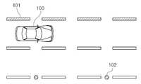
현재 제안되어 있는 종래의 운전자에 대한 차량 시계 보조 기술들에 대한 예가 도 1에 도시되어 있다.An example of vehicle clock assistance techniques for a conventional driver that is currently proposed is shown in FIG. 1.
도 1을 참조하면, 노면에 차선이 도색되어 있지 않거나 폭우 또는 폭설 등의 기상상태로 인하여 전방의 시계가 불안정하여 차량의 안정적인 주행이 어려운 경우를 위하여, 차량이 운전되고 있는 노면에 자석봉(102)를 일정한 간격으로 매설하고, 이를 자계 검지기기를 사용하여 자석봉의 위치를 인식하고 이를 따라 주행하는 방법이 제시되고 있다. 또한, 노면상에 유도선(101)을 설치하는 기술 역시 제시되어 왔는데, 유도선(101)의 종류로는 널리 알려진 어두울 때의 시계 보조 재료인 형광물질을 이용한 유도선(101)이나, 노면의 차선에 요철을 설치하여, 차선을 벗어날 시에 차량에 진동을 주게 하는 방식, 또는 차선에 열선을 장착하여 노면에 폭설이 오더라도 차선 부분에는 눈이 쌓이지 않게 하는 방식 등이 알려져 있는 상태이다.Referring to FIG. 1, a
하지만 상기 언급한 종래의 차량 운전자에 대해 시계 보조 기술은 다음과 같은 문제점이 내재되어 있다. 먼저 차선에 열선을 장착하는 방식은 실질적으로 어두운 상태, 폭우, 폭설이 계속되고 있는 중에는 차량의 시계 자체가 불안정하여 시계 보조에 있어서 실질적인 효율성이 거의 없다. 또한 차선에 요철을 설치하여 차선 이탈을 방지하는 방식은, 차선을 이탈하기 직전에만 비로소 차선 이탈에 대한 정보를 운전자가 감지할 수 있기 때문에, 차선 이탈에 대한 예방 차원으로는 부족한 점이 있다. 그리고 형광물질을 이용한 유도선(101)의 경우에도, 상기 열선 장착 방식과 비슷하게 시계 보조에 있어서 실질적인 효율성이 거의 없는 문제점이 있다.However, for the above-mentioned conventional vehicle driver, the clock assistance technology has the following problems. First of all, the method of attaching a hot wire to a lane is substantially unstable because the vehicle's clock itself is unstable in a dark state, heavy rain, and heavy snow. In addition, the method of preventing lane departure by installing irregularities in the lane may be insufficient as a preventive measure for lane departure because the driver may sense information about the lane departure only before the vehicle leaves the lane. In addition, even in the case of the
노면에 일정한 간격으로 자석봉(102)을 매설하고, 이를 자계검지기기를 이용하여 주행하는 방법의 경우에는, 자석을 매설하기 위하여 도면에 천공을 하여야 하고, 이로 인하여 도로가 쉽게 균열을 일으키는 등의 파손 위험이 내재되고 있다는 문제점이 제시되고 있고, 또한, 직접 차량 하방을 지나는 자석봉의 경우에만 인식이 가능하여, 차량 전방의 자석봉에 대한 위치 감지가 불가능하기 때문에, 역시 차선 유지 및 차선 이탈에 대한 예방 차원의 기술로는 문제가 있게 되어, 이에 대한 새로운 기술의 제시가 요구되고 있는 실정이다.In the case of embedding the
상기 언급한 문제점을 해결하기 위하여, 본 발명에서는, 노면에 차선이 도색되어 있지 않거나 폭우 또는 폭설 등으로 인하여 차량 운전시 차량 운전자의 시계가 불안정할 시에, 보다 효과적이고 직접적으로 운전자에게 시계 정보를 보조하는 기술을 제공하는 동시에, 전방의 시계를 미리 감지 및 예측하여 운전자에게 제공함으로써, 운전자에 대한 시계 보조 효과를 최대화하고, 도면에 다른 보조 장치를 설치하는 과정 없이 도로의 상태 그대로의 정보를 활용하여 시계 보조 기능을 수행하여, 경제적인 효과 역시 제공하는 데 그 목적이 있다.In order to solve the above-mentioned problems, in the present invention, when the vehicle driver's clock is unstable when driving a vehicle due to heavy rain or heavy snow, the present invention provides more effective and direct clock information to the driver. While providing assistive technology, the driver can detect and predict ahead of time and provide the driver with the ability to maximize the effect of the watch on the driver and to use information on the road without the need to install other aids in the drawing. The purpose is to provide an economical effect by performing a clock assist function.
상기 목적을 달성하기 위하여, 본 발명의 실시 예에 따른 랜드마크를 이용한 조향 제어 장치는, 차량 주행 시 도로에 설치된 랜드마크를 촬영하는 차량에 설치된 촬영장치와, 촬영장치의 영상을 분석하여 차량의 현 좌표 데이터를 생성하는 좌표 제어부와, 차량의 목표 좌표 데이터와 좌표 제어부로부터 수신한 현 좌표 데이터를 비교하여 정상 운전상태여부를 판단하고, 정상 운전상태여부 데이터를 생성하는 차선 제어부와, 좌표 제어부로부터 수신한 현 좌표 데이터, 차선 제어부로부터 수신한 목표 좌표, 및 정상 운전상태여부 데이터를 표시하는 표시부를 포함한다.In order to achieve the above object, a steering control apparatus using a landmark according to an embodiment of the present invention, the image pickup device is installed on the vehicle for photographing the landmarks installed on the road while driving the vehicle, by analyzing the image of the image pickup device of the vehicle From the coordinate control unit for generating the current coordinate data, the target coordinate data of the vehicle and the current coordinate data received from the coordinate control unit to determine whether the normal driving state, and the lane control unit for generating the normal driving state data, and from the coordinate control unit And a display unit for displaying the current coordinate data received, the target coordinate received from the lane controller, and the normal driving state data.
또한 좌표 제어부와 차선 제어부는, 랜드마크의 실제 높이, 영상에 나타난 높이, 촬영 배율, 랜드마크와 차량 사이의 거리, 촬영장치의 초점 및 초점 거리, 촬영장치의 중심점, 차선 중심선, 랜드마크와 차선 중심선 사이의 수직 거리, 랜드 마크와 촬영장치의 시축 사이의 수직 거리 등을 바탕으로 현재의 좌표와 목표 좌표를 연산하고, 이를 바탕으로 조향 제어를 수행하게 된다.The coordinate control unit and the lane control unit may include the actual height of the landmark, the height shown in the image, the shooting magnification, the distance between the landmark and the vehicle, the focusing and focal length of the photographing apparatus, the center point of the photographing apparatus, the lane centerline, the landmark and the lane Based on the vertical distance between the center line, the vertical distance between the landmark and the visual axis of the photographing apparatus, the current coordinates and the target coordinates are calculated, and the steering control is performed based on this.
본 발명의 실시 예에 따른 랜드마크를 이용한 조향 제어 장치에 의하면, 차량에 설치된 촬영 장치를 이용하여 랜드마크에서 발생하는 조명 등 강우나 폭설 속에서도 감지가 가능한 정보를 얻게 되며, 본 발명의 실시 예에서는 특히 가로등을 랜드마크로 하고 있기 때문에, 도로에 기본적으로 설치된 랜드마크를 사용하고 있어, 높은 정확도로 운전자에게 시계 보조를 제공할 수 있으며, 따로 보조 장치를 도로변에 설치할 필요가 없어 경제적인 효과 역시 얻을 수 있다. 또한, 전방의 랜드마크를 촬영하여 차선 유지 방향을 미리 제시하기 때문에, 차선유지 또는 조향 제어에 있어서 사고 예방적인 기술을 제공할 수 있는 효과가 있다.According to the steering control apparatus using a landmark according to an embodiment of the present invention, by using the photographing device installed in the vehicle to obtain information that can be detected even in heavy rain or heavy snow, such as lights generated from the landmark, in the embodiment of the present invention In particular, since the streetlight is a landmark, it uses a landmark installed on the road, which can provide the driver with high accuracy and provides economical benefits by eliminating the need for an auxiliary device on the side of the road. have. In addition, since the lane maintenance direction is presented in advance by photographing the landmarks in front of the vehicle, there is an effect of providing an accident prevention technology in lane keeping or steering control.
이하, 도 2 및 도 3을 참조하여 본 발명의 실시 예에 따른 랜드마크를 이용한 조향 제어 장치에 대하여 설명하기로 한다.Hereinafter, a steering control apparatus using a landmark according to an exemplary embodiment of the present invention will be described with reference to FIGS. 2 and 3.
본 발명에서 조향 제어 장치는 차선 유도 등 차량 조향을 제어하는 모든 기능을 수행하는 장치를 포괄한다.The steering control device in the present invention encompasses a device that performs all functions for controlling vehicle steering, such as lane guidance.
도 2 및 도 3은, 본 발명의 실시 예에 따른 랜드마크를 이용한 조향 제어 장치를 이용한 차량의 운전 형태, 개략적인 연산에 필요한 정보, 및 차량내의 개략적인 장치도를 도시한 것이다.2 and 3 illustrate a driving pattern of a vehicle using a steering control device using a landmark according to an exemplary embodiment of the present invention, information required for rough calculation, and a schematic device diagram in a vehicle.
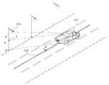
먼저 도 2를 참조하면, 일반적으로 자동차가(201)가 도로를 주행할 때의 모 습을 도시하고 있다. 본 발명의 실시 예에서는, 일반적인 도로에서 차선의 중심선(202)을 유지하면서 주행하는 것을 보조하기 위한 장치를 제공하기 위한 것이며, 따라서, 차량(201)이 차선의 중심선(202)을 벗어날 때 경고 표시 제공 기능을 수행하거나, 조향을 직접적으로 차량의 ECU 등 프로세서에서 제어하여 일정 각도 이상의 조향 장치(Steering Wheel) 제어에 대한 금지 기능 또는 자동 주행 시스템의 도입으로 차량(201)이 안전운행을 할 수 있는 발명을 제공하기로 한다.First, referring to FIG. 2, the
상기의 목적을 달성하기 위하여, 즉, 차량(201)이 차선의 중심(202)선을 따라 주행하도록 하기 위하여, 차량 내부 또는 외부에 소정의 높이(h)부분에 촬영장치(식별번호 없음)를 설치하고, 상기 촬영장치는, 일정한 소정의 높이(H)를 가지는 랜드마크(200)를 촬영하여 상기 랜드마크(200)의 촬영 영상에 근거하여 차량이 차선의 중심선(202)을 유지하면서 주행하고 있는지를 판단하게 된다.In order to achieve the above object, that is, in order for the
랜드마크(200)는 일정 간격으로 도로변 또는 도로의 중앙선 등에 설치되어 있는 촬영 가능한 표지를 뜻한다. 본 발명의 실시 예에서는 도로변 또는 도로의 중앙선에 일반적으로 설치될 수 있는 가로등(200)을 랜드마크로 사용하고 있다. 가로등(200)은, 야간, 강우, 폭설 시에도 인식이 가능한 불빛을 발생하고 있기 때문에, 차량(201)에 설치된 촬영 장치가 불빛을 인식하여 가로등(200)의 높이를 연산할 수 있기 때문에, 랜드마크로서 적합한 장치가 될 것이다. 하지만, 가로등(200) 이외에도, 본 발명의 실시에 사용하기 위해 도로변 또는 도로 중앙선에 설치된 전용 랜드마크가 사용될 수도 있으며, 랜드마크에는 야간, 강우, 또는 폭설 시에도 촬영장치에 의해 인식될 수 있는 조명 장치 등이 설치되어 있어야 할 것이다.The
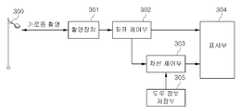
도 3은 상기 기능을 수행하기 위한 본 발명의 실시 예에 따른 랜드마크를 이용한 조향 제어 장치의 장치도를 도시한 것이다.3 illustrates an apparatus diagram of a steering control apparatus using a landmark according to an exemplary embodiment of the present invention for performing the above function.
도 3을 참조하면, 먼저 랜드마크(300)를 촬영할 수 있도록 차량의 일정 부분에 설치되어 있고, 랜드마크(300)를 촬영한 영상을 송출할 수 있는 촬영장치(301)를 포함할 수 있다. 촬영장치(301)는, 일반목적의 카메라를 포함할 수 있으며, 바람직하게는 최근 그 사용 빈도가 급속하게 증가하고 있는, 차량의 앞 유리창에 설치되어 차량의 운전시 전방을 촬영 및 저장할 수 있는 차량용 블랙박스의 촬영장치를 포함할 수 있다. 촬영장치(301)는 도로에 설치된 랜드마크(300)를 촬영하여 그 영상을 분석하도록 실시간으로 송출하는 기능을 수행하게 된다.Referring to FIG. 3, first, the
촬영장치(301)는 차량의 전면에 보이는 랜드마크(300)를 촬영하기 위한 어느 장소에도 설치될 수 있다. 본 발명의 실시 예에서는 촬영장치(301)는 차량의 앞 유리창의 상단부 중앙에 설치될 수 있는데, 바람직하게는 리어 뷰 미러(Rear View Mirror)(백미러라고도 함)의 위치에 설치될 수 있다. 본 발명의 목적이 차량이 차선 중심선을 따라 주행하도록 하는 것이기 때문에, 상기 언급한 리어 뷰 미러 위치가 차량의 좌우 중심에 위치하고 있으므로, 상기 촬영장치(301) 역시 리어 뷰 미러 위치에 설치함으로써, 차량이 바람직하게 차선의 중심선으로 주행할 수 있도록 할 수 있는 것이다.The photographing
랜드마크를 이용한 조향 제어 장치는 또한 좌표 제어부(302)를 포함할 수 있다. 좌표 제어부(302)는 이하 설명할 설정된 직교 좌표계를 가지고 있으며, 이에 근거하여 촬영장치(301)로부터 수신한 촬영 영상을 분석한 뒤, 차량의 현 좌표 데 이터를 생성하게 된다. 상세한 차량의 현 좌표 데이터 생성 방법에 대해서는 도 4를 참조하여 설명하기로 한다.The steering control device using the landmark may also include a
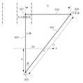
도 4는 촬영 장치를 중심으로 좌표 제어부(302)가 차량의 현 좌표 데이터를 생성하는 방법을 도시하고 있다.4 illustrates a method in which the
도 4를 참조하면, 좌표축이 설정된 좌표 평면(304)은 기본적으로 촬영장치(301)가 위치한 렌즈 등의 표면 위치를 의미하는 것이다. 좌표축 설정 시에 그 원점 O는 촬영장치(301)의 중심점을 의미하고 있다. 촬영장치(301)는 또한 초점 f0을 가지고 있기 때문에, 촬영장치(301)의 후면에 가상적인 초점 f0을 포함할 수 있다. 그리고 촬영장치(301)의 초점 f0과 촬영장치(301)의 중심점 사이의 거리는 초점거리 f로 설정될 수 있을 것이다. 원점 O, 초점 f0, 및 초점거리 f는 촬영장치(301)의 종류에 따라서 달라질 수 있음은 당연할 것이다.Referring to FIG. 4, the
촬영장치(301)가 위치한 렌즈 등의 표면 위치에 따라 설정되는 좌표축이 설정된 좌표 평면(304)의 X축은 차량이 달리고 있는 도로면과 평행한 선을 의미한다. 좌표 평면(304)의 X축을 설정할 때는, 촬영장치(301)가 전방을 촬영 시에 촬영된 영상을 분석하여 도로면을 추출하고, 도로면에 평행하며 원점 O를 지나는 선을 X축으로 설정할 수 있다. 하지만 이 방법 이외에도, 양 앞 또는 뒷바퀴가 지면과 닿는 점을 잇는 선과 평행하며 원점 O를 지나는 선 등 차량이 위치하고 있는 지면과 평행한 선을 설정할 수 있는 방법이라면 어느 것이나 가능할 것이다. 좌표 평면(304)의 X축이 설정되고 나면, Y축은 X축에 수직하고 원점 O를 지나는 선을 설정하는 것으로 쉽게, 직교 좌표계를 설정할 수 있을 것이다. 시축(400)은 원점 O와 초점 f0를 지나는 선의 연장선으로서 차량이 현재 방향으로 계속 주행 시 랜드마크(300)를 지나칠 때 랜드마크(300)와 차량 사이의 거리 Xd를 계산하는 데 사용된다.The X axis of the coordinate
촬영장치(301)가 랜드마크(300)를 촬영한 영상이 수신되면, 좌표 제어부(302)는 미리 저장된 촬영장치(301) 정보를 활용하여 촬영장치(301)의 초점 f0로부터 랜드마크(300) 사이의 거리 D를 계산하게 된다. D를 계산하기 위하여 좌표 제어부(302)에는 촬영장치(301)의 배율이 저장될 수 있으며, 저장된 촬영장치(301)의 배율 정보를 활용하여 초점으로부터 랜드마크(300)의 최 상단 U를 잇는 선이 촬영장치(301)와 만나는 점, 즉 직교 좌표계와 만나는 점을 분석하게 되고, 현 좌표 u(Xs, Ys)의 값을 가지는 데이터를 생성하게 된다.When the photographing
현 좌표 u가 생성되면, 현 좌표에 따른 차선 정보(즉, 현재 차량이 몇 차선에서 주행하고 있는지에 대한 정보)를 획득하기 위하여 초점 f0과 랜드마크 사이의 수평거리 D(즉 촬영장치와 랜드마크를 수평하게 잇는 초점 f0와 점 L 사이의 거리)를 계산하게 된다. 촬영장치(301)가 차량에 설치되어 있으므로, 지면과의 높이 h가 존재할 수 있으며, 랜드마크(300)의 높이가 H로서 미리 좌표 제어부(302)에 저장되어 있다면, 촬영장치(301)과 랜드마크(300) 사이의 높이 차는 H-h가 될 것이다. 또한 현 좌표 데이터 u가 존재하기 때문에, 초점 f0에서 랜드마크(300)를 잇는 수평선이 좌표와 만나는 점 I 사이의 거리 f'은 다음과 같이 정의될 수 있다.When the current coordinate u is generated, the horizontal distance D between the focal point f and the landmark (ie, the photographing apparatus and the landmark) in order to obtain lane information according to the current coordinate (that is, information on which lane the vehicle is currently traveling). The distance between the focal point f0 and the point L that connects horizontally is calculated. Since the photographing

이후, 초점 f0와 랜드마크(300)사이의 수평거리 D는 다음의 식을 이용하여 계산될 수 있다.Then, the horizontal distance D between the focal point f and the

초점 f0로부터 랜드마크(300) 사이의 수평거리 D가 계산되면, 시축(400)으로부터 랜드마크 사이의 수직거리 Xd가 다음과 같은 식으로부터 계산될 수 있다.If the horizontal distance D between the

Xd가 계산된다면, 좌표 제어부(302)는 Xd 및 미리 저장된 도로 정보에 근거하여, 현재 차량이 놓여있는 차선 수를 인식할 수 있을 것이다.If Xd is calculated, the coordinate
이상의 계산을 통하여, 좌표 제어부(302)는 촬영장치(301)에서 촬영된 영상을 분석하여 현 좌표 데이터를 생성하고, 현 좌표 데이터를 통하여 현재 차량이 놓여있는 차선 수를 인식하여, 현 좌표 데이터 및 현 주행 차선 데이터를 송출하게 되는 것이다.Through the above calculations, the coordinate
본 발명의 실시 예에 따른 랜드마크를 이용한 조향 제어 장치는 차선 제어부(303) 역시 포함할 수 있다. 차선 제어부(303)는 좌표 제어부(302)로부터 현 좌표 데이터 및 현 주행 차선 데이터를 수신하고, 현 주행 차선 데이터에 근거하여 목표 좌표 데이터를 생성한 뒤에, 이를 현 좌표 데이터와 비교하여 현재 차량이 놓 여있는 차선에서 차량이 차선의 중심선을 따라서 안전하게 주행하고 있는지를 판단하는 기능을 하게 된다. 추가적으로 차선 제어부(303)는 목표 좌표 데이터 및 차량이 차선의 중심선을 따라 운행하고 있는지에 대한 판단 결과 데이터를 송출하는 기능을 하게 된다.The steering control apparatus using the landmark according to the embodiment of the present invention may also include a
따라서 차선 제어부(303)는 가장 먼저 현 주행 차선 데이터에 근거하여 목표 좌표 데이터를 생성하는 기능을 수행하게 되는데, 이에 대한 설명이 도 5에 도시되어 있다.Accordingly, the
도 5를 참조하면, 차량이 차선의 중심선을 통해서 주행하고 있을 때의 모습을 수식적으로 표현하고 있으며, 이를 통하여 목표 좌표계를 계산할 수 있다. 먼저 차량이 차선의 중심선을 통해 주행하고 있다면, 도 4에서 언급한 시축(400)은 차선의 중앙점(501)을 잇는 차선의 중심선과 일치하게 될 것이다.Referring to FIG. 5, a state in which the vehicle is driving through the center line of the lane is expressed by a formula, and the target coordinate system may be calculated through this. First, if the vehicle is driving through the center line of the lane, the
차선 제어부(303)는 수신한 현 주행 차선 데이터를 이용하여 현 차선의 중심선과 랜드마크(300)사이의 수직거리 S를 계산할 수 있다. 차선 제어부(303)에는 상기의 계산을 위하여 각 차선의 폭 및 랜드마크(300)과 최 외곽 차선(본 발명의 실시 예에서는 도로변에 랜드마크(300)가 존재하므로 도로변과 가장 가까운 차선을 의미한다.)의 중심선 사이의 거리를 저장할 수 있을 것이다.The
이후 차선 제어부(303)는 현 주행 차선 데이터를 이용하여 현 위치에서 현 차선의 중심선과 랜드마크(300)사이의 수평 거리를 계산하게 되는데, 본 발명의 실시 예에서는 현 차선의 중심선과 현재 차량이 주행하고 있는 위치 사이의 거리가 1미터 내로 작다고 가정할 수 있으므로, 현 위치에서 현 차선의 중심선과 랜드마크(300) 사이의 거리는 도 4에서 계산한 D과 같다고 가정하고 있다. 하지만, 도 5에서의 D를 정확하게 계산하기 위한 다른 계산 방법이 사용될 수도 있을 것이다.Thereafter, the
이후, 도 5에서 차선의 중심선과 목표 좌표에서의 초점 f0과 랜드마크(300) 사이의 수평선이 이루는 각 θ을 계산하게 되는데, 각 θ는 다음과 같은 식을 통하여 얻을 수 있다.Subsequently, in FIG. 5, an angle θ formed by the horizontal line between the center line of the lane and the focal point f0 at the target coordinates and the

각 θ가 계산되면, 목표 좌표(정확히는 목표 X좌표) Xs'를 계산하는 방법은 다음과 같다.Once the angle θ is calculated, the method of calculating the target coordinate (exactly the target X coordinate) Xs' is as follows.

초점거리 f는 촬영장치(301)의 초점거리이므로 도 4에서의 f와 같은 값일 것이다.Since the focal length f is the focal length of the photographing
차선 제어부(303)는 계산된 목표 X좌표와, 좌표 제어부(302)로부터 수신한 현 좌표 데이터 중 X좌표 데이터를 비교하게 된다. 차선의 중심선을 따라서 차량이 주행하고 있는지를 판단하기 위해서는 Y좌표는 필요가 없으므로, 현 좌표 데이터를 수신할 때 X좌표 데이터만을 고려의 대상으로 하게 된다. 따라서, 본 발명의 다른 실시 예에서는 좌표 제어부(302)가 현 좌표 데이터를 연산 및 생성시에, X좌표만을 연산 및 생성할 수도 있을 것이다. 차선 제어부(303)는 현 좌표 데이터 및 목표 X좌표 데이터를 비교하여 그 차이를 분석하게 되며, 상기 차이가 소정 값 a(예를 들어 10cm)를 벗어날 경우 현재 주행이 위험한 상태임을 운전자에게 알리는 판단 결과 데이터를 송신하는 기능을 수행할 수 있다.The
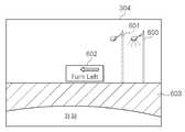
본 발명의 실시 예에 따른 랜드마크를 이용한 조향 제어 장치는, 상기 좌표 제어부(302) 또는 차선 제어부(303)를 통해 수신한 현 좌표 데이터, 현 주행 차선 데이터, 상기 차선 제어부(303)로부터 수신한 목표 좌표, 및 정상 운전상태여부 데이터를 표시하는 표시부(304)를 포함할 수 있다. 표시부(304)의 표시 기능에 대한 예가 도 6에 도시되어 있다.Steering control apparatus using a landmark according to an embodiment of the present invention, the current coordinate data received through the coordinate
도 6을 참조하면, 표시부(304)는 현 좌표 데이터를 좌표 제어부(302)로부터 수신하고, 이를 분석하여 촬영 영상으로 표현하게 된다. 본 발명의 실시 예에서는 현 좌표 데이터에 대응하는 랜드마크의 제 1위치 영상(600)을 표시부에 표현하고 있다. 그리고 차선 제어부(303)로부터 목표 좌표 데이터를 수신하게 되고, 이를 또한 랜드마크의 제2위치 영상(601)으로 표현하게 된다. 본 발명의 실시 예에서는 도 6에 도시된 바와 같이 실질적인 랜드마크 영상으로 표현을 하고 있지만, 좌표를 직접 표시하거나 상기 영상을 아예 표시하지 않는 방법 또한 사용될 수 있을 것이다.Referring to FIG. 6, the
표시부(304)는 또한 차선 제어부(303)로부터 수신한 정상 운전상태여부에 대한 판단 결과 데이터를 표시할 수 있다. 차선의 중심선으로 차량이 주행하고 있는지에 대해서 판단한 결과를 표시할 수 있는데, 본 발명의 실시 예에서는 정상 운전 상태에서는 표시부(304)에 아무런 표시도 되지 않고, 차선의 중심선에서 소정 범위(예를 들어 10cm)를 벗어나게 되면 목표 좌표의 위치에 따라서, 왼쪽 또는 오른쪽으로 조향을 제어하라는 표시를 하게 된다. 하지만, 이외에도 차량이 차선의 중심선으로 주행할 수 있도록 운전자에게 정보를 전달하는 진동, 음향 및 다른 시각적 표현 중 하나 이상을 포함할 수 있을 것이다. 또는, 자동차의 운전 자동 제어 시스템에 의해서 조향을 제한하거나, 직접 자동차가 운전자 대신에 조향을 제어하는 방식이 사용될 수도 있을 것이다.The
본 발명의 다른 실시 예에서는, 상기 언급한 좌표 제어부(302) 및 차선 제어부(303)의 좌표 데이터, 주행 차선 데이터, 및 정상 운전상태여부 데이터 중 하나 이상의 생성에 필요한 정보를 미리 저장하기 위한 도로 정보 저장부(305)를 더 포함할 수 있다. 도로 정보 저장부(305)의 데이터 베이스 구조에 대한 예가 도 7에 도시되어 있다.According to another embodiment of the present invention, road information for storing in advance information necessary for generating one or more of the above-described coordinate data, driving lane data, and normal driving state data of the coordinate
도 7을 참조하면, 먼저 랜드마크는 도로에 따라서 일정하거나 다를 수 있으므로, 도로 명에 대한 데이터(701)가 포함될 수 있으며, 도로 명에 따른 랜드마크의 크기에 대한 데이터(702) 역시 포함될 수 있다. 또한, 자동차 별로 지면으로부터 촬영장치까지의 높이가 다를 수 있으므로, 촬영장치의 초기 설치 시에, 입력을 통하여 랜드마크의 높이와 촬영 장치의 높이 차이에 대한 데이터(703) 역시 포함될 수 있다. 그리고 차선간 거리(704) 데이터가 좌표 제어부 대신에 도로 정보 저장부(305)에 저장되어 좌표 제어부의 필요에 따라서 공급될 수 있으며, 최 근접차선의 중심과 랜드마크 사이의 거리, 즉 도로변에 랜드마크가 설치된 경우에는 가장 바깥쪽의 차선, 중앙선에 랜드마크가 설치된 경우에는 1차선의 중심과 랜드마크 사이의 거리에 대한 데이터(705)가 각각 좌표 제어부 및 차선 제어부에 제공될 수 있다. 또한 현 좌표 데이터(706) 또는 목표 좌표 데이터(707) 역시 포함될 수 있는데, 도로 정보 저장부(305)는 본 발명의 실시를 위해 필요한 상기 언급하지 않은 데이터를 추가적으로 저장할 수 있으며, 도로 정보 저장부(305)에 상기 정보가 저장된다면, 좌표 제어부 및 차선 제어부에서의 연산이 더욱 용이하게 이루어질 수 있을 것이다. 여기서 현 좌표 데이터(706) 또는 목표 좌표 데이터(707)는 각각 좌표 제어부(302) 또는 차선 제어부(303)에 별도로 저장될 수 있다.Referring to FIG. 7, since a landmark may be constant or different according to a road,
상기 언급한 본 발명의 실시 예에 따른 랜드마크를 이용한 조향 제어 장치를 이용한 조향 제어 방법에 대한 개략적인 흐름도가 도 8에 도시되어 있다. 본 발명에서 조향 제어 방법은 차선 유지를 위한 조향 제어 방법 등을 포괄하는 개념이다. 각 단계별 기능의 수행에 있어서, 본 발명의 실시 예에 따른 랜드마크를 이용한 조향 제어 장치가 사용되고 있으므로, 상기 언급한 랜드마크를 이용한 조향 제어 장치에 대한 설명과 중복되는 부분은 생략하기로 한다.8 is a schematic flowchart of a steering control method using a steering control apparatus using a landmark according to the above-described embodiment of the present invention. In the present invention, the steering control method is a concept encompassing a steering control method for lane keeping. In the performance of each step, since the steering control apparatus using the landmark according to the embodiment of the present invention is used, a portion overlapping with the description of the steering control apparatus using the above-mentioned landmark will be omitted.
먼저, 촬영장치(301)가 랜드마크(300)에 대한 영상을 촬영하는 단계(S1)가 수행된다. 상기 촬영 장치가 랜드마크(300)를 촬영하는 단계(S1)는 랜드마크(300)가 설치된 간격에 따라서 주기적으로 계속 수행되거나, 도 8에 도시된 바와 같이 모든 연산 및 판단이 종료된 후에 다시 랜드마크(300)를 인식하여 촬영할 수 있다. 이후, 촬영장치(301)에 의해 촬영된 영상 데이터를 분석하고 상기 언급한 좌표 제어부(302)의 연산 수행에 따라서 현 좌표 데이터 u(Xs,Ys)를 생성하는 단계(S2)가 수행된다. 현 좌표 데이터 u가 생성되면, 좌표 제어부(302)는, 좌표 제어부(302), 도로정보 저장부(305), 및 차선 제어부(303)의 데이터 베이스 중 하나 이상으로부터 도로 정보(도 7의 데이터 베이스에 포함된 모든 정보를 포함한다.)를 수신하여 분석하고, 이를 통하여 차선 정보, 즉 현 주행 차선 데이터를 생성하는 단계(S3)를 수행하게 된다.First, a step (S1) in which the photographing
차선 제어부(303)는 현 좌표 데이터 및 현 주행 차선 데이터를 좌표 제어부(302)로부터 수신하게 되고, 이를 제외한 도로 정보를 좌표 제어부(302)는, 좌표 제어부(302), 도로정보 저장부(305), 및 차선 제어부(303)의 데이터 베이스 중 하나 이상으로부터 수신하게 되며, 이에 근거하여 상기 언급한 연산 방법을 통하여 목표 좌표 u'(Xs') 데이터를 연산 및 생성하는 단계(S4)를 수행하게 된다. 이후, 차선 제어부(303)는 현 좌표 데이터의 X좌표 Xs와 목표 좌표 Xs'의 차이를 계산하여, 상기 차이가 일정 값 a(예를 들어 10cm)를 벗어나는지를 판단하는 단계(S5)를 수행하게 된다. 현 좌표 데이터의 X좌표 Xs와 목표 좌표 Xs'의 차이가 소정 값 a 이상인 경우, 조향을 제어하도록 표시부(305)가 사용자에게 표시하거나, 차량의 자동 제어 시스템이 직접 조향을 제어하는 단계(S6)를 수행하게 되며, 이후 다시 랜드마크(300)를 촬영하는 단계(S1)를 수행하게 된다.The
상기 언급한 본 발명의 실시 예에 따른 랜드마크를 이용한 조향 제어 장치에 대한 실시 방법에 대한 설명은, 오로지 설명적인 용도로만 사용되어야 할 것이며, 특허청구범위를 제한하는 것은 아니다. 또한, 상기 언급한 실시 예 이외에도, 본 발명의 기능과 동일한 기능을 하는 균등한 발명 역시 본 발명의 권리 범위에 속하 는 것은 당연할 것이다.Description of the implementation method for the steering control device using the landmark according to the embodiment of the present invention mentioned above, should be used only for illustrative purposes, it does not limit the claims. In addition to the above-mentioned embodiment, it will be obvious that the equivalent invention having the same function as that of the present invention also belongs to the scope of the present invention.
도 1은 종래의 조향 제어 또는 차선 유도 장치의 예를 도시한 것이다.1 illustrates an example of a conventional steering control or lane guidance device.
도 2는 본 발명의 실시 예에 따른 랜드마크를 이용한 조향 제어 장치를 이용한 자동차의 운전 예를 도시한 것이다.2 illustrates a driving example of a vehicle using a steering control apparatus using a landmark according to an exemplary embodiment of the present invention.
도 3은 본 발명의 실시 예에 따른 랜드마크를 이용한 조향 제어 장치의 장치도를 도시한 것이다.3 illustrates an apparatus diagram of a steering control apparatus using a landmark according to an exemplary embodiment of the present invention.
도 4는 본 발명의 실시 예에 따른 랜드마크를 이용한 조향 제어 장치를 이용하여 좌표 제어부가 현 좌표 데이터 및 현 주행 차선 데이터를 생성하는 연산 방법을 도시한 것이다.4 is a diagram illustrating an operation method of generating, by a coordinate controller, current coordinate data and current driving lane data using a steering control apparatus using a landmark according to an exemplary embodiment of the present invention.
도 5는 본 발명의 실시 예에 따른 랜드마크를 이용한 조향 제어 장치를 이용하여 차선 제어부가 목표 좌표 데이터를 생성하는 연산 방법을 도시한 것이다.FIG. 5 illustrates an operation method of generating, by a lane controller, target coordinate data using a steering control apparatus using a landmark according to an exemplary embodiment of the present invention.
도 6은 본 발명의 실시 예에 따른 랜드마크를 이용한 조향 제어 장치에서 표시부의 표시 예를 도시한 것이다.6 illustrates an example of displaying a display unit in a steering control apparatus using a landmark according to an exemplary embodiment of the present invention.
도 7은 본 발명의 실시 예에 따른 랜드마크를 이용한 조향 제어 장치에서 도로 정보 저장부에 저장되는 데이터의 구조 예를 도시한 것이다.7 illustrates an example of a structure of data stored in a road information storage unit in a steering control apparatus using a landmark according to an exemplary embodiment of the present invention.
도 8은 본 발명의 실시 예에 따른 랜드마크를 이용한 조향 제어 장치를 이용한 조향제어 방법의 흐름도를 도시한 것이다.8 is a flowchart illustrating a steering control method using a steering control apparatus using a landmark according to an exemplary embodiment of the present invention.
Claims (20)
Translated fromKoreanPriority Applications (2)
| Application Number | Priority Date | Filing Date | Title |
|---|---|---|---|
| KR1020090105519AKR101265110B1 (en) | 2009-11-03 | 2009-11-03 | Steering control leading apparatus using landmark and method thereby |
| US12/912,933US20110102579A1 (en) | 2009-11-03 | 2010-10-27 | Steering control leading apparatus using landmark and method thereby |
Applications Claiming Priority (1)
| Application Number | Priority Date | Filing Date | Title |
|---|---|---|---|
| KR1020090105519AKR101265110B1 (en) | 2009-11-03 | 2009-11-03 | Steering control leading apparatus using landmark and method thereby |
Publications (2)
| Publication Number | Publication Date |
|---|---|
| KR20110048798A KR20110048798A (en) | 2011-05-12 |
| KR101265110B1true KR101265110B1 (en) | 2013-05-20 |
Family
ID=43925021
Family Applications (1)
| Application Number | Title | Priority Date | Filing Date |
|---|---|---|---|
| KR1020090105519AActiveKR101265110B1 (en) | 2009-11-03 | 2009-11-03 | Steering control leading apparatus using landmark and method thereby |
Country Status (2)
| Country | Link |
|---|---|
| US (1) | US20110102579A1 (en) |
| KR (1) | KR101265110B1 (en) |
Cited By (1)
| Publication number | Priority date | Publication date | Assignee | Title |
|---|---|---|---|---|
| KR101502071B1 (en)* | 2013-07-05 | 2015-03-12 | 충남대학교산학협력단 | Camera Data Generator for Landmark-based Vision Navigation System and Computer-readable Media Recording Program for Executing the Same |
Families Citing this family (15)
| Publication number | Priority date | Publication date | Assignee | Title |
|---|---|---|---|---|
| JP2015005193A (en)* | 2013-06-21 | 2015-01-08 | 富士重工業株式会社 | Vehicle drive support device |
| KR101498973B1 (en)* | 2013-11-21 | 2015-03-05 | 현대모비스(주) | Parking asistance system and parking asistance method |
| KR101830249B1 (en)* | 2014-03-20 | 2018-03-29 | 한국전자통신연구원 | Position recognition apparatus and method of mobile object |
| KR101573764B1 (en)* | 2014-07-28 | 2015-12-02 | 현대모비스 주식회사 | System and method for recognizing driving road of vehicle |
| US11372479B2 (en) | 2014-11-10 | 2022-06-28 | Irisvision, Inc. | Multi-modal vision enhancement system |
| US11546527B2 (en) | 2018-07-05 | 2023-01-03 | Irisvision, Inc. | Methods and apparatuses for compensating for retinitis pigmentosa |
| CA2971163A1 (en) | 2014-11-10 | 2016-05-19 | Visionize Corp. | Methods and apparatus for vision enhancement |
| US11144119B2 (en) | 2015-05-01 | 2021-10-12 | Irisvision, Inc. | Methods and systems for generating a magnification region in output video images |
| CN112902975B (en)* | 2015-02-10 | 2024-04-30 | 御眼视觉技术有限公司 | Autonomous vehicle navigation method, readable device, server, vehicle and system |
| KR102278387B1 (en)* | 2015-07-07 | 2021-07-16 | 주식회사 만도 | Distance calculating apparatus and distance calculating method and driving assist apparatus and driving assist system |
| KR101659251B1 (en)* | 2016-04-19 | 2016-09-23 | 현대건설주식회사 | Discernment system for driving lane data or road information and discernment method using the same |
| KR20180099280A (en)* | 2017-02-28 | 2018-09-05 | 삼성전자주식회사 | Method and device to generate virtual lane |
| CN112534467A (en) | 2018-02-13 | 2021-03-19 | 弗兰克.沃布林 | Method and apparatus for contrast sensitivity compensation |
| CN109543636B (en)* | 2018-11-29 | 2020-12-15 | 连尚(新昌)网络科技有限公司 | A method and device for detecting sharp bends in roads |
| DE102020214327A1 (en)* | 2020-11-13 | 2022-05-19 | Continental Automotive Gmbh | Method and system for determining a position of a traffic lane |
Citations (3)
| Publication number | Priority date | Publication date | Assignee | Title |
|---|---|---|---|---|
| JP2001514110A (en) | 1997-08-23 | 2001-09-11 | ローベルト ボツシユ ゲゼルシヤフト ミツト ベシユレンクテル ハフツング | Information indication method in vehicle |
| JP2004078334A (en)* | 2002-08-12 | 2004-03-11 | Nissan Motor Co Ltd | Travel route generation device |
| JP2005104451A (en)* | 2004-06-21 | 2005-04-21 | Noriyuki Sugimoto | Automation of vehicle speed setting of rfid detector and cruise control device having variable function for communication area of traffic signs/road indications navigator system |
Family Cites Families (3)
| Publication number | Priority date | Publication date | Assignee | Title |
|---|---|---|---|---|
| US7510038B2 (en)* | 2003-06-11 | 2009-03-31 | Delphi Technologies, Inc. | Steering system with lane keeping integration |
| US7590263B2 (en)* | 2004-11-30 | 2009-09-15 | Honda Motor Co., Ltd. | Vehicle vicinity monitoring apparatus |
| US9052207B2 (en)* | 2009-10-22 | 2015-06-09 | Tomtom Polska Sp. Z O.O. | System and method for vehicle navigation using lateral offsets |
- 2009
- 2009-11-03KRKR1020090105519Apatent/KR101265110B1/enactiveActive
- 2010
- 2010-10-27USUS12/912,933patent/US20110102579A1/ennot_activeAbandoned
Patent Citations (3)
| Publication number | Priority date | Publication date | Assignee | Title |
|---|---|---|---|---|
| JP2001514110A (en) | 1997-08-23 | 2001-09-11 | ローベルト ボツシユ ゲゼルシヤフト ミツト ベシユレンクテル ハフツング | Information indication method in vehicle |
| JP2004078334A (en)* | 2002-08-12 | 2004-03-11 | Nissan Motor Co Ltd | Travel route generation device |
| JP2005104451A (en)* | 2004-06-21 | 2005-04-21 | Noriyuki Sugimoto | Automation of vehicle speed setting of rfid detector and cruise control device having variable function for communication area of traffic signs/road indications navigator system |
Cited By (1)
| Publication number | Priority date | Publication date | Assignee | Title |
|---|---|---|---|---|
| KR101502071B1 (en)* | 2013-07-05 | 2015-03-12 | 충남대학교산학협력단 | Camera Data Generator for Landmark-based Vision Navigation System and Computer-readable Media Recording Program for Executing the Same |
Also Published As
| Publication number | Publication date |
|---|---|
| KR20110048798A (en) | 2011-05-12 |
| US20110102579A1 (en) | 2011-05-05 |
Similar Documents
| Publication | Publication Date | Title |
|---|---|---|
| KR101265110B1 (en) | Steering control leading apparatus using landmark and method thereby | |
| US8054201B2 (en) | Surroundings monitoring device for vehicle | |
| CN103874931B (en) | For the method and apparatus of the position of the object in the environment for asking for vehicle | |
| US8600673B2 (en) | Driving assistance apparatus | |
| JP6189815B2 (en) | Traveling line recognition system | |
| EP2605185B1 (en) | Detection of obstacles at night by analysis of shadows | |
| KR101655553B1 (en) | Driver assistance apparatus and method | |
| US8560220B2 (en) | Method and apparatus for determining a plausible lane for guiding a vehicle and an automobile | |
| KR20140109990A (en) | Determining a vertical profile of a vehicle environment by means of a 3d camera | |
| JP3888166B2 (en) | Vehicle driving support device | |
| JP2015069289A (en) | Lane recognition device | |
| US20140152432A1 (en) | Method for Detecting a Traffic Lane by Means of a Camera | |
| KR102295992B1 (en) | Methods and devices for supporting driver assistance systems in automobiles | |
| JP2008097279A (en) | Vehicle exterior information display device | |
| JP2009122825A (en) | Traveling state determination device | |
| JP5274984B2 (en) | Driving support system | |
| JP5677281B2 (en) | Vehicle detection device | |
| KR20150055183A (en) | Apparatus for displaying traffic lane using head-up display and method thereof | |
| KR20220148378A (en) | Apparatus for assisting driving of a host vehicle and method therof | |
| JP2010176592A (en) | Driving support device for vehicle | |
| JP4986069B2 (en) | Ambient monitoring device for vehicles | |
| KR20230071921A (en) | Vehicle control system and navigating method using vehicle control system | |
| CN208360051U (en) | Seven road integrated form visual perception systems of one kind and vehicle | |
| JP2006344133A (en) | Road marking line detection device | |
| WO2019039106A1 (en) | Image recognition device |
Legal Events
| Date | Code | Title | Description |
|---|---|---|---|
| A201 | Request for examination | ||
| PA0109 | Patent application | Patent event code:PA01091R01D Comment text:Patent Application Patent event date:20091103 | |
| PA0201 | Request for examination | ||
| PG1501 | Laying open of application | ||
| PE0902 | Notice of grounds for rejection | Comment text:Notification of reason for refusal Patent event date:20121112 Patent event code:PE09021S01D | |
| E701 | Decision to grant or registration of patent right | ||
| PE0701 | Decision of registration | Patent event code:PE07011S01D Comment text:Decision to Grant Registration Patent event date:20130507 | |
| GRNT | Written decision to grant | ||
| PR0701 | Registration of establishment | Comment text:Registration of Establishment Patent event date:20130510 Patent event code:PR07011E01D | |
| PR1002 | Payment of registration fee | Payment date:20130513 End annual number:3 Start annual number:1 | |
| PG1601 | Publication of registration | ||
| FPAY | Annual fee payment | Payment date:20160427 Year of fee payment:4 | |
| PR1001 | Payment of annual fee | Payment date:20160427 Start annual number:4 End annual number:4 | |
| FPAY | Annual fee payment | Payment date:20170510 Year of fee payment:5 | |
| PR1001 | Payment of annual fee | Payment date:20170510 Start annual number:5 End annual number:5 | |
| PR1001 | Payment of annual fee | Payment date:20180511 Start annual number:6 End annual number:6 | |
| PR1001 | Payment of annual fee | Payment date:20190513 Start annual number:7 End annual number:7 | |
| PR1001 | Payment of annual fee | Payment date:20200512 Start annual number:8 End annual number:8 | |
| PR1001 | Payment of annual fee | Payment date:20210510 Start annual number:9 End annual number:9 | |
| PR1001 | Payment of annual fee | Payment date:20220511 Start annual number:10 End annual number:10 | |
| PR1001 | Payment of annual fee | Payment date:20230511 Start annual number:11 End annual number:11 | |
| PR1001 | Payment of annual fee | Payment date:20250423 Start annual number:13 End annual number:13 |