KR101264122B1 - Low power variable stiffness unit and robot comprising the same - Google Patents
Low power variable stiffness unit and robot comprising the sameDownload PDFInfo
- Publication number
- KR101264122B1 KR101264122B1KR1020120067575AKR20120067575AKR101264122B1KR 101264122 B1KR101264122 B1KR 101264122B1KR 1020120067575 AKR1020120067575 AKR 1020120067575AKR 20120067575 AKR20120067575 AKR 20120067575AKR 101264122 B1KR101264122 B1KR 101264122B1
- Authority
- KR
- South Korea
- Prior art keywords
- cable
- input
- pulleys
- axial direction
- side pulley
- Prior art date
- Legal status (The legal status is an assumption and is not a legal conclusion. Google has not performed a legal analysis and makes no representation as to the accuracy of the status listed.)
- Active
Links
- 230000007423decreaseEffects0.000claimsabstractdescription6
- 238000000034methodMethods0.000claimsdescription13
- 208000027418Wounds and injuryDiseases0.000description2
- 238000006243chemical reactionMethods0.000description2
- 230000006835compressionEffects0.000description2
- 238000007906compressionMethods0.000description2
- 238000006073displacement reactionMethods0.000description2
- 238000012986modificationMethods0.000description2
- 230000004048modificationEffects0.000description2
- 238000006467substitution reactionMethods0.000description2
- 230000005540biological transmissionEffects0.000description1
- 230000006378damageEffects0.000description1
- 208000014674injuryDiseases0.000description1
- 238000010297mechanical methods and processMethods0.000description1
Images


Classifications
- B—PERFORMING OPERATIONS; TRANSPORTING
- B25—HAND TOOLS; PORTABLE POWER-DRIVEN TOOLS; MANIPULATORS
- B25J—MANIPULATORS; CHAMBERS PROVIDED WITH MANIPULATION DEVICES
- B25J19/00—Accessories fitted to manipulators, e.g. for monitoring, for viewing; Safety devices combined with or specially adapted for use in connection with manipulators
- B25J19/06—Safety devices
- B25J19/068—Actuating means with variable stiffness
- B—PERFORMING OPERATIONS; TRANSPORTING
- B25—HAND TOOLS; PORTABLE POWER-DRIVEN TOOLS; MANIPULATORS
- B25J—MANIPULATORS; CHAMBERS PROVIDED WITH MANIPULATION DEVICES
- B25J9/00—Programme-controlled manipulators
- B25J9/10—Programme-controlled manipulators characterised by positioning means for manipulator elements
- B25J9/104—Programme-controlled manipulators characterised by positioning means for manipulator elements with cables, chains or ribbons
- B25J9/1045—Programme-controlled manipulators characterised by positioning means for manipulator elements with cables, chains or ribbons comprising tensioning means
- F—MECHANICAL ENGINEERING; LIGHTING; HEATING; WEAPONS; BLASTING
- F16—ENGINEERING ELEMENTS AND UNITS; GENERAL MEASURES FOR PRODUCING AND MAINTAINING EFFECTIVE FUNCTIONING OF MACHINES OR INSTALLATIONS; THERMAL INSULATION IN GENERAL
- F16H—GEARING
- F16H55/00—Elements with teeth or friction surfaces for conveying motion; Worms, pulleys or sheaves for gearing mechanisms
- F16H55/32—Friction members
- F16H55/36—Pulleys
Landscapes
- Engineering & Computer Science (AREA)
- Mechanical Engineering (AREA)
- Robotics (AREA)
- General Engineering & Computer Science (AREA)
- Manipulator (AREA)
- Transmission Devices (AREA)
Abstract
Translated fromKoreanDescription
Translated fromKorean본 발명은 가변 강성 장치 및 이를 포함하는 로봇에 관한 것으로, 케이블 구동 방식의 저전력 구동 가능한 가변 강성 장치 및 이를 포함하는 로봇에 관한 것이다.The present invention relates to a variable stiffness device and a robot including the same. The present invention relates to a variable power stiffness device and a robot including the same.
로봇의 안정성과 성능을 동시에 만족하기 위한 방법으로, 다양한 센서를 활용한 제어 알고리즘으로 능동적인 제어를 구현하는 전자적인 방법과, 외부에서 가해지는 힘에 반응할 수 있는 물리적인 장치를 활용한 가변 강성 장치(Variable-stiffness)를 사용하는 기계적인 방법이 있다.In order to satisfy the stability and performance of the robot at the same time, the variable rigidity using the electronic method that implements active control with the control algorithm using various sensors and the physical device that can respond to external force There is a mechanical method that uses variable-stiffness.
여기서, 가변 강성 장치는 로봇의 조인트 부분에 설치되어 상해가 발생할 수 있는 외력 이상에서 동력 전달을 신속히 제어하는 역할을 한다. 이러한 가변 강성 장치를 통해 작동 공간을 공유하는 인간과 기구 자체의 안정성을 높일 수 있다Here, the variable rigid device is installed in the joint portion of the robot serves to quickly control the power transmission in the external force that may cause injury. This variable stiffness device can increase the stability of the human being and the instrument itself sharing the operating space.
가변 강성 장치는 입력/출력 유닛의 체결력을 위해 축 방향으로 배치된 스프링이 포함된다. 통상적으로 이러한 스프링의 압축 변위를 조정함으로써 강성을 조절하였다. 그러나, 이는 스프링을 압축하는 과정 및 스프링의 압축 변위를 조절하는 과정에서 많은 에너지가 소요되며 에너지 손실이 큰 문제점이 있다.The variable stiffness device includes a spring disposed axially for the fastening force of the input / output unit. Typically the stiffness was adjusted by adjusting the compression displacement of these springs. However, this requires a lot of energy in the process of compressing the spring and the process of adjusting the compression displacement of the spring has a large energy loss problem.
이에, 본 발명은 상기한 문제점을 해결하기 위한 것으로, 에너지 손실을 줄이고 적은 힘으로도 강성을 조절할 수 있는 가변 강성 장치 및 이를 포함하는 로봇 제공하는 것을 그 목적으로 한다.Accordingly, an object of the present invention is to provide a variable stiffness device and a robot including the same, which can reduce the energy loss and control the stiffness with a small force.
상기 목적을 달성하기 위한 본 발명은, 케이블과, 상기 케이블이 입력되고 축방향을 따라 단계적으로 직경이 증가 또는 감소하는 적어도 둘의 풀리를 포함하는 입력측 풀리 조립체와, 상기 입력측 풀리와 동일한 회전축으로 연결되고, 상기 케이블의 입력 방향과 상이한 방향으로 상기 케이블을 출력하는 출력측 풀리와, 상기 케이블을 고정하고 축방향으로 상기 회전축에 슬라이드 가능하게 결합하여 상기 적어도 둘의 풀리 중 어느 하나의 풀리로 상기 케이블을 안내하는 강성 조절부를 포함하는 가변 강성 장치를 제공한다.The present invention for achieving the above object is connected to the input side pulley assembly comprising a cable, at least two pulleys in which the cable is input and the diameter increases or decreases stepwise along the axial direction, and connected to the same rotation axis as the input side pulley An output side pulley for outputting the cable in a direction different from an input direction of the cable, and fixing the cable and slidably engaging the rotation shaft in an axial direction to connect the cable to one of the at least two pulleys. It provides a variable stiffness device including a guiding stiffness control.
바람직하게는, 상기 케이블의 입력 방향과 상기 케이블의 출력 방향은 수직하게 형성될 수 있다.Preferably, the input direction of the cable and the output direction of the cable may be formed vertically.
바람직하게는, 상기 회전축은, 상기 회전축의 축방향으로 외주연의 일부가 절개되어 슬라이드 홈부가 형성될 수 있다.Preferably, the rotating shaft, a portion of the outer periphery in the axial direction of the rotating shaft may be cut to form a slide groove.
바람직하게는, 상기 슬라이드 홈부에는 상기 회전축의 외주연의 절개폭 보다 넓게 형성되는 좌우 홈부가 형성될 수 있다.Preferably, the slide groove portion may be formed in the left and right groove portion that is formed wider than the cutting width of the outer circumference of the rotating shaft.
바람직하게는, 상기 축방향을 기준으로 어느 한 방향을 향하여 단계적으로 직경이 증가할 수 있다.Preferably, the diameter may increase in stages toward one direction based on the axial direction.
바람직하게는, 상기 강성 조절부에는 상기 케이블이 삽입되어 고정되는 제1 케이블 홀이 형성되고, 상기 출력측 풀리의 외주연에는 상기 제1 케이블 홀을 통과한 상기 케이블이 삽입되어 상기 케이블이 상기 출력측 풀리의 밖으로 나오도록 안내하는 제2 케이블 홀이 형성될 수 있다.
Preferably, the rigidity control unit is formed with a first cable hole is inserted into the cable is fixed, the outer periphery of the output side pulley is inserted into the cable passing through the first cable hole is inserted into the output side pulley A second cable hole may be formed to guide out of the.
상기 목적을 달성하기 위한 다른 발명은, 케이블과, 상기 케이블이 입력되고 축방향을 따라 단계적으로 직경이 증가 또는 감소하는 적어도 둘의 풀리를 포함하는 입력측 풀리 조립체와, 상기 입력측 풀리와 동일한 회전축으로 연결되고, 상기 케이블의 입력 방향과 상이한 방향으로 상기 케이블을 출력하는 출력측 풀리와, 상기 케이블을 고정하고 축방향으로 상기 회전축에 슬라이드 가능하게 결합하여 상기 적어도 둘의 풀리 중 어느 하나의 풀리로 상기 케이블을 안내하는 강성 조절부를 포함하는 가변 강성 장치가 구비된 로봇을 제공한다.Another invention for achieving the above object is connected to an input side pulley assembly including a cable, at least two pulleys in which the cable is input and the diameter increases or decreases stepwise along the axial direction, and connected to the same rotation axis as the input side pulley An output side pulley for outputting the cable in a direction different from an input direction of the cable, and fixing the cable and slidably engaging the rotation shaft in an axial direction to connect the cable to one of the at least two pulleys. Provided is a robot with a variable stiffness device including a stiffness control for guiding.
바람직하게는, 상기 로봇은, 상기 케이블의 입력 방향과 상기 케이블의 출력 방향은 수직하게 형성될 수 있다.Preferably, the robot, the input direction of the cable and the output direction of the cable may be formed vertically.
바람직하게는, 상기 회전축은, 상기 회전축의 축방향으로 외주연의 일부가 절개되어 슬라이드 홈부가 형성될 수 있다.Preferably, the rotating shaft, a portion of the outer periphery in the axial direction of the rotating shaft may be cut to form a slide groove.
바람직하게는, 상기 슬라이드 홈부에는 상기 회전축의 외주연의 절개폭 보다 넓게 형성되는 좌우 홈부가 형성될 수 있다.Preferably, the slide groove portion may be formed in the left and right groove portion that is formed wider than the cutting width of the outer circumference of the rotating shaft.
바람직하게는, 상기 축방향을 기준으로 어느 한 방향을 향하여 단계적으로 직경이 증가할 수 있다.Preferably, the diameter may increase in stages toward one direction based on the axial direction.
본 발명에 따른 가변 강성 장치에 따르면, 직경이 상이한 복수개의 풀리 중 어느 하나를 선택하여 입력측 힘과 출력측 힘을 수직하게 형성시킴으로써, 작은 힘으로도 강성을 조절할 수 있는 유리한 효과를 제공한다.According to the variable stiffness device according to the present invention, by selecting any one of a plurality of pulleys having a different diameter to form an input force and an output force vertically, it provides an advantageous effect that the rigidity can be adjusted even with a small force.
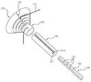
도 1은 본 발명의 바람직한 일실시예에 따른 가변 강성 장치, 로봇의 액츄에이터 및 로봇의 링크에 연결되는 케이블를 도시한 도면,
도 2는 본 발명의 바람직한 일실시예에 따른 가변 강성 장치를 도시한 사시도,
도 3은 도 2에서 도시한 가변 강성 장치의 분해 사시도,
도 4는 도 1에서 도시한 입력측 풀리 조립체의 최대 직경 풀리에 케이블이 걸리는 상태를 도시한 평면도,
도 5는 도 1에서 도시한 입력측 풀리 조립체의 최소 직경 풀리에 케이블이 걸리는 상태를 도시한 평면도,
도 6은 최대 직경 풀리외 최소 직경 풀리에서의 강성을 비교한 도면이다.1 is a view showing a cable connected to a variable rigidity device, an actuator of a robot, and a link of a robot according to an embodiment of the present invention;
2 is a perspective view showing a variable rigid device according to an embodiment of the present invention,
3 is an exploded perspective view of the variable rigid device shown in FIG.
Figure 4 is a plan view showing a state that the cable is caught in the pulley maximum diameter pulley of the input side pulley assembly shown in FIG.
FIG. 5 is a plan view showing a cable hooked to a minimum diameter pulley of the input pulley assembly shown in FIG. 1;
6 is a view comparing the stiffness in the minimum diameter pulley other than the maximum diameter pulley.
이하, 본 발명의 바람직한 실시예를 첨부된 도면들을 참조하여 상세히 설명한다. 우선 각 도면의 구성 요소들에 참조 부호를 부가함에 있어서, 동일한 구성 요소들에 대해서는 비록 다른 도면상에 표시되더라도 가능한 한 동일한 부호를 가지도록 하고 있음에 유의해야 한다. 또한, 이하에서 본 발명의 바람직한 실시예를 설명할 것이나, 본 발명의 기술적 사상은 이에 한정하거나 제한되지 않고 당업자에 의해 변형되어 다양하게 실시될 수 있음은 물론이다.
Hereinafter, preferred embodiments of the present invention will be described in detail with reference to the accompanying drawings. In the drawings, the same reference numerals are used to designate the same or similar components throughout the drawings. In addition, the preferred embodiments of the present invention will be described below, but it is needless to say that the technical idea of the present invention is not limited thereto and can be variously modified by those skilled in the art.
본 발명은 힘의 입력 방향과 출력 방향을 대략적으로 수직하게 전환하는 직경이 상이한 복수 개의 풀리(pully) 중 어느 하나를 선택하여 강성을 조절하는 것을 기술적 특징으로 한다.The present invention is characterized in that the stiffness is adjusted by selecting any one of a plurality of pulleys having different diameters that switch the input direction and the output direction of the force approximately vertically.
도 1은 본 발명의 바람직한 일실시예에 따른 가변 강성 장치, 로봇의 액츄에이터 및 로봇의 링크에 연결되는 케이블를 도시한 도면이고, 도 2는 본 발명의 바람직한 일실시예에 따른 가변 강성 장치의 분해 사시도이며, 도 3은 도 2에서 도시한 가변 강성 장치의 분해 사시도이다.
1 is a view showing a variable rigidity device, an actuator of a robot and a cable connected to a link of the robot according to a preferred embodiment of the present invention, Figure 2 is an exploded perspective view of a variable rigidity device according to a preferred embodiment of the present invention 3 is an exploded perspective view of the variable rigid device shown in FIG. 2.
여기서, 도 2 및 도 3은 본 발명을 개념적으로 명확히 이해하기 위하여, 주요 특징 부분만을 명확히 도시한 것이며, 그 결과 도해의 다양한 변형이 예상되며, 도면에 도시된 특정 형상에 의해 본 발명의 범위가 제한될 필요는 없다.2 and 3 clearly illustrate only the main features in order to conceptually clearly understand the present invention, and as a result, various modifications of the drawings are contemplated, and the scope of the present invention is limited by the specific shapes shown in the drawings. There is no need to be limited.
도 1 내지 도 3을 병행 참조하면, 본 발명의 바람직한 일실시예에 따른 가변 강성 장치(100)는 케이블(110)과, 입력측 풀리 조립체(120)와 출력측 풀리(130)와 강성 조절부(140)를 포함한다.
1 to 3, the
먼저, 도 1을 참조하면, 케이블(110)은 로봇의 액츄에이터와 링크를 연결하여 동력을 전달하는 부재이다.First, referring to FIG. 1, the
도 2를 참조하면, 입력측 풀리 조립체(120)는 입력단에서 케이블(110)을 입력 받는다. 입력측 풀리 조립체(120)는 케이블(110)이 감기는 복수개의 풀리(121,122,123,124)가 동일축 상에 형성된다. 각각의 복수개의 풀리(121,122,123,124)는 직경이 상이하게 형성되며, 입력측 풀리 조립체(120)의 축방향으로 따라 단계적으로 직경이 증가 또는 감소하도록 배치될 수 있다.2, the
이러한, 입력측 풀리 조립체(120)는 원뿔대 형상의 몸체의 외연을 따라 복수 개의 홈이 형성된 모양으로 실시될 수 있다. 여기서, 복수개의 홈이 상술한 풀리(121,122,123,124)에 해당한다. 한편, 각 풀리(121,122,123,124)를 포함한 입력측 풀리 조립체(120)에는 축방향으로 절개부(125)가 형성된다. 절개부(125)를 지나 케이블(110)이 입력측 풀리 조립체(120) 중심에 있는 강성 조절부(140)로 안내된다.
The
출력측 풀리(130)는 입력측 풀리 조립체(120)와 동일한 회전축(150)과 연결되게 형성된다. 일실시예에 있어서, 출력측 풀리(130)는 입력측 풀리 조립체(120)와 일체로 형성될 수 있다. 즉, 출력측 풀리(130)는 입력측 풀리 조립체(120)의 단부에서 연장되어 소정의 직경을 갖도록 형성된다.The
여기서, 입력측 풀리 조립체(120)와 출력측 풀리(130)는 그 형상 및 기능적 특성에 따라 구분되어 설명되었을 뿐, 연결된 하나의 수단일 수 있다.Here, the
출력측 풀리(130)의 외주연에는 제2 케이블 홀(131)이 형성된다. 제2 케이블 홀(131)은 후술되는 강성 조절부(140)에서 안내되는 케이블(10)이 통과한다.
A
도 2 및 도 3을 참조하면, 강성 조절부(140)는 입력측 풀리 조립체(120)의 복수 개의 풀리(121,122,123,124) 중 어느 하나를 선택하고 선택된 풀리에 케이블(110)을 안내하는 역할을 한다. 이러한 강성 조절부(140)는 회전축(150) 내부에 축방향으로 슬라이드 가능하게 결합한다. 이에, 강성 조절부(140)는 회전축(150) 내부에서 축방향으로 이동한다.2 and 3, the
일실시예에 있어서, 회전축(150)에는 슬라이드 홈(151)이 형성된다. 슬라이드 홈(151)은 회전축(150)의 외주연의 일부가 절개되어 형성된다. 이러한 슬라이드 홈(151)에는 회전축(150)의 외주연의 절개폭 보다 넓게 형성되는 좌우 홈부(151a)가 부가되어 형성될 수 있다. 강성 조절부(140)는 이러한 슬라이드 홈(151)에 이동 가능하게 끼워지도록, 슬라이드 홈(151)에 대응되는 형상을 갖는다.In one embodiment, the
강성 조절부(140)에는 케이블(110)을 안내하는 슬롯(142)이 길이방향으로 형성되며, 이 슬롯(142)의 바닥에는 제1 케이블 홀(141)이 형성된다. 도 3을 참조하면, 모두 3개의 제1 케이블 홀(141)이 형성되어 있으나, 본 발명은 이에 한정되지 않는다. 제1 케이블 홀(141)에는 입력단과 연결되는 케이블(110)이 통과된다.
The
이하, 도 4 내지 도 6을 참조하여 상술한 일실시예에 따른 가변 강성 장치의 작동 과정을 설명한다.Hereinafter, an operation process of the variable rigid device according to the exemplary embodiment described above will be described with reference to FIGS. 4 to 6.
도 4는 도 1에서 도시한 입력측 풀리 조립체의 최대 직경 풀리에 케이블이 걸리는 상태를 도시한 평면도이고, 도 5는 도 1에서 도시한 입력측 풀리 조립체의 최소 직경 풀리에 케이블이 걸리는 상태를 도시한 평면도이며, 도 6은 최대 직경 풀리외 최소 직경 풀리에서의 강성을 비교한 도면이다.FIG. 4 is a plan view showing the cable hooked to the maximum diameter pulley of the input side pulley assembly shown in FIG. 1, and FIG. 6 is a view comparing the stiffness in the minimum diameter pulley other than the maximum diameter pulley.
도 4를 참조하면, 입력단에 연결된 케이블(110)은 입력측 풀리 조립체(120)의 최대 직경 풀리(121)에 걸려 절개부(125)를 통과하여 강성 조절부(140)의 제1 케이블 홀(141)에 삽입된다. (이를 이하, “제1 상태”라 한다.) 앞서 살펴본 바와 같이, 강성 조절부(140)는 회전축(150) 내부에서 축방향으로 이동 가능하게 구성된다. 외부 조작에 의해, 강성 조절부(140)가 이동하게 되면, 케이블(110)이 걸리는 풀리가 달라지게 된다.Referring to FIG. 4, the
도 5를 참조하면, 강성 조절부(140)가 이동하여 케이블(110)이 입력측 풀리 조립체(120)의 최소 직경 풀리(124)에 걸리게 된다.(이를 이하, “제2 상태”라 한다)Referring to FIG. 5, the
도 6의 (a)는, 제1 상태에서 출력측의 힘 F1과 입력측의 케이블의 반력 F2로 나타낸다. 도 6의 (b)는 제2 상태에서 출력측의 힘 F1과 입력측의 케이블의 반력 F3로 나타낸다. 또한, 출력측 풀리(130)의 반지름을 r1으로 나타내고, 최대 직경 풀리(121)의 반지름을 r2로 나타내며, 최소 직경 풀리(124)의 반지름을 r3로 나타낸다.Fig. 6A shows the force F1 on the output side and the reaction force F2 on the cable on the input side in the first state. Fig. 6B shows the force F1 on the output side and the reaction force F3 on the cable on the input side in the second state. In addition, the radius of the
이때, 제1 상태와 제2 상태의 F1의 크기가 일정하더라도, F2와 F3는 상이하게 나타난다. 이는 r2와 r3가 다르기 때문이다. F2보다 F3가 크기 때문에, 동일한 외력(F1)에 대응하는 강성이 달라질 수 있다. 다시 말해서, 강성 조절부(140)를 축방향으로 이동시킴에 따라 케이블(110)이 걸리는 풀리를 달리하여 강성을 조절할 수 있는 것이다.
At this time, even if the size of F1 in the first state and the second state is constant, F2 and F3 appear differently. This is because r2 and r3 are different. Since F3 is larger than F2, the stiffness corresponding to the same external force F1 may vary. In other words, as the
이상의 설명은 본 발명의 기술 사상을 예시적으로 설명한 것에 불과한 것으로서, 본 발명이 속하는 기술 분야에서 통상의 지식을 가진 자라면 본 발명의 본질적인 특성에서 벗어나지 않는 범위 내에서 다양한 수정, 변경 및 치환이 가능할 것이다. 따라서, 본 발명에 개시된 실시예 및 첨부된 도면들은 본 발명의 기술 사상을 한정하기 위한 것이 아니라 설명하기 위한 것이고, 이러한 실시예 및 첨부된 도면에 의하여 본 발명의 기술 사상의 범위가 한정되는 것은 아니다. 본 발명의 보호 범위는 아래의 청구범위에 의하여 해석되어야 하며, 그와 동등한 범위 내에 있는 모든 기술 사상은 본 발명의 권리범위에 포함되는 것으로 해석되어야 할 것이다.It will be apparent to those skilled in the art that various modifications, substitutions and substitutions are possible, without departing from the scope and spirit of the invention as disclosed in the accompanying claims. will be. Accordingly, the embodiments disclosed in the present invention and the accompanying drawings are not intended to limit the technical spirit of the present invention but to describe the present invention, and the scope of the technical idea of the present invention is not limited by the embodiments and the accompanying drawings. . The protection scope of the present invention should be interpreted by the following claims, and all technical ideas within the equivalent scope should be interpreted as being included in the scope of the present invention.
110 : 케이블
120 : 입력측 풀리 조립체
121,122,123,124 : 입력측 풀리
124 : 절개부
130 : 출력측 풀리
140 : 강성 조절부
150 : 회전축110: cable
120: input side pulley assembly
121,122,123,124: Input side pulley
124: incision
130: output side pulley
140: rigidity control unit
150: rotation axis
Claims (11)
Translated fromKorean상기 케이블이 입력되고 축방향을 따라 단계적으로 직경이 증가 또는 감소하는 적어도 둘의 풀리를 포함하는 입력측 풀리 조립체;
상기 입력측 풀리와 동일한 회전축으로 연결되고, 상기 케이블의 입력 방향과 상이한 방향으로 상기 케이블을 출력하는 출력측 풀리;
상기 케이블을 고정하고 축방향으로 상기 회전축에 슬라이드 가능하게 결합하여 상기 적어도 둘의 풀리 중 어느 하나의 풀리로 상기 케이블을 안내하는 강성 조절부
를 포함하는 가변 강성 장치.cable;
An input side pulley assembly comprising at least two pulleys in which the cable is input and the diameter increases or decreases stepwise along the axial direction;
An output side pulley connected to the same rotation shaft as the input side pulley and outputting the cable in a direction different from the input direction of the cable;
Fixing the cable and slidably coupled to the rotating shaft in the axial direction to guide the cable to any one of the pulleys of the at least two pulleys
Variable stiffness device comprising a.
상기 케이블의 입력 방향과 상기 케이블의 출력 방향은 수직하게 형성되는 것을 특징으로 하는 가변 강성 장치.The method according to claim 1,
And the input direction of the cable and the output direction of the cable are formed vertically.
상기 회전축은,
상기 회전축의 축방향으로 외주연의 일부가 절개되어 슬라이드 홈부가 형성되는 것을 특징으로 하는 가변 강성 장치.The method according to claim 1,
The rotation shaft
A portion of the outer periphery is cut in the axial direction of the rotating shaft to form a sliding groove portion.
상기 슬라이드 홈부에는 상기 회전축의 외주연의 절개폭 보다 넓게 형성되는 좌우 홈부가 형성되는 것을 특징으로 하는 가변 강성 장치.The method of claim 3,
Variable slide device is characterized in that the slide groove portion is formed with a left and right groove portion formed wider than the cutting width of the outer circumference of the rotating shaft.
상기 축방향을 기준으로 어느 한 방향을 향하여 단계적으로 직경이 증가하는 것을 특징으로 하는 가변 강성 장치.The method according to claim 1,
Variable stiffness device characterized in that the diameter increases step by step toward the direction relative to the axial direction.
상기 강성 조절부에는 상기 케이블이 삽입되어 고정되는 제1 케이블 홀이 형성되고,
상기 출력측 풀리의 외주연에는 상기 제1 케이블 홀을 통과한 상기 케이블이 삽입되어 상기 케이블이 상기 출력측 풀리(130)의 밖으로 나오도록 안내하는 제2 케이블 홀이 형성되는 것을 특징으로 하는 가변 강성 장치.
것을 특징으로 하는 가변 강성 장치.The method according to claim 1,
The rigidity control unit is formed with a first cable hole is fixed to the cable is inserted,
And a second cable hole formed at an outer circumference of the output side pulley to insert the cable passing through the first cable hole to guide the cable out of the output side pulley (130).
Variable rigid device, characterized in that.
상기 케이블의 입력 방향과 상기 케이블의 출력 방향은 수직하게 형성되는 것을 특징으로 하는 로봇.The method of claim 7, wherein
And the input direction of the cable and the output direction of the cable are formed vertically.
상기 회전축은,
상기 회전축의 축방향으로 외주연의 일부가 절개되어 슬라이드 홈부가 형성되는 것을 특징으로 하는 로봇.The method of claim 7, wherein
The rotation shaft
A part of the outer periphery is cut in the axial direction of the rotating shaft to form a slide groove.
상기 슬라이드 홈부에는 상기 회전축의 외주연의 절개폭 보다 넓게 형성되는 좌우 홈부가 형성되는 것을 특징으로 하는 로봇.10. The method of claim 9,
The slide groove portion is a robot, characterized in that the left and right grooves are formed wider than the cutting width of the outer circumference of the rotating shaft.
상기 축방향을 기준으로 어느 한 방향을 향하여 단계적으로 직경이 증가하는 것을 특징으로 하는 로봇.The method of claim 7, wherein
Robot, characterized in that for increasing the diameter step by step toward the direction relative to the axial direction.
Priority Applications (1)
| Application Number | Priority Date | Filing Date | Title |
|---|---|---|---|
| KR1020120067575AKR101264122B1 (en) | 2012-06-22 | 2012-06-22 | Low power variable stiffness unit and robot comprising the same |
Applications Claiming Priority (1)
| Application Number | Priority Date | Filing Date | Title |
|---|---|---|---|
| KR1020120067575AKR101264122B1 (en) | 2012-06-22 | 2012-06-22 | Low power variable stiffness unit and robot comprising the same |
Publications (1)
| Publication Number | Publication Date |
|---|---|
| KR101264122B1true KR101264122B1 (en) | 2013-05-14 |
Family
ID=48666191
Family Applications (1)
| Application Number | Title | Priority Date | Filing Date |
|---|---|---|---|
| KR1020120067575AActiveKR101264122B1 (en) | 2012-06-22 | 2012-06-22 | Low power variable stiffness unit and robot comprising the same |
Country Status (1)
| Country | Link |
|---|---|
| KR (1) | KR101264122B1 (en) |
Cited By (3)
| Publication number | Priority date | Publication date | Assignee | Title |
|---|---|---|---|---|
| CN107486850A (en)* | 2017-09-08 | 2017-12-19 | 四川大学 | A kind of Wire driven robot robot variation rigidity elastic joint |
| CN109623871A (en)* | 2019-03-01 | 2019-04-16 | 河北工业大学 | A kind of master-passive stiffness-shift joint and its stiffness tuning method |
| CN112077834A (en)* | 2020-08-24 | 2020-12-15 | 枣庄学院 | Reconfigurable rope-driven series-parallel variable-rigidity household service mechanical arm |
Citations (2)
| Publication number | Priority date | Publication date | Assignee | Title |
|---|---|---|---|---|
| JP2008232360A (en) | 2007-03-22 | 2008-10-02 | Toshiba Corp | Wire drive mechanism, robot arm mechanism and robot |
| KR101052519B1 (en) | 2009-11-13 | 2011-07-29 | 삼성중공업 주식회사 | Cable joint type robot joint device and automated robot using the same |
- 2012
- 2012-06-22KRKR1020120067575Apatent/KR101264122B1/enactiveActive
Patent Citations (2)
| Publication number | Priority date | Publication date | Assignee | Title |
|---|---|---|---|---|
| JP2008232360A (en) | 2007-03-22 | 2008-10-02 | Toshiba Corp | Wire drive mechanism, robot arm mechanism and robot |
| KR101052519B1 (en) | 2009-11-13 | 2011-07-29 | 삼성중공업 주식회사 | Cable joint type robot joint device and automated robot using the same |
Cited By (6)
| Publication number | Priority date | Publication date | Assignee | Title |
|---|---|---|---|---|
| CN107486850A (en)* | 2017-09-08 | 2017-12-19 | 四川大学 | A kind of Wire driven robot robot variation rigidity elastic joint |
| CN107486850B (en)* | 2017-09-08 | 2020-05-01 | 四川大学 | A variable-stiffness elastic joint for a flexible cable-driven robot |
| CN109623871A (en)* | 2019-03-01 | 2019-04-16 | 河北工业大学 | A kind of master-passive stiffness-shift joint and its stiffness tuning method |
| CN109623871B (en)* | 2019-03-01 | 2023-05-23 | 河北工业大学 | An active-passive variable stiffness joint and its stiffness adjustment method |
| CN112077834A (en)* | 2020-08-24 | 2020-12-15 | 枣庄学院 | Reconfigurable rope-driven series-parallel variable-rigidity household service mechanical arm |
| CN112077834B (en)* | 2020-08-24 | 2021-11-05 | 枣庄学院 | Reconfigurable rope-driven series-parallel variable-rigidity household service mechanical arm |
Similar Documents
| Publication | Publication Date | Title |
|---|---|---|
| KR101264122B1 (en) | Low power variable stiffness unit and robot comprising the same | |
| US20140263493A1 (en) | Headband variable stiffness | |
| US10295016B2 (en) | Plate link chain | |
| US9464702B2 (en) | Slider apparatus | |
| US20190184784A1 (en) | Clutch apparatus for stabilizer | |
| WO2016059832A1 (en) | Headphone | |
| US20120141218A1 (en) | Hand drill | |
| JP5475918B1 (en) | Torque hinge or torque limiter | |
| JP2020521926A (en) | Electronically controlled valve for shock absorber | |
| KR20120101123A (en) | Apparatus comprising rotatable member | |
| KR102571453B1 (en) | electronic expansion valve | |
| US20140174783A1 (en) | Cable protection and guide device | |
| MY202294A (en) | Pitch control system | |
| WO2016177569A3 (en) | Electric motor comprising an insulating element with guide means | |
| MX2014012602A (en) | Variable stiffness downhole tool housing. | |
| KR102228667B1 (en) | Width adjusting type wiring-protector | |
| EP3156325A3 (en) | Saturation-controlled variable damper systems and methods | |
| US10495119B2 (en) | Spool valve | |
| CN105564273A (en) | Transmission drive unit of a seat adjusting device | |
| JP2016121757A (en) | Feed screw device and actuator using the same | |
| US20210285517A1 (en) | Long object guiding device and partition member | |
| CN104584762B (en) | Push rod mechanism for garden tools | |
| KR101528500B1 (en) | Feathering Apparatus of Blade of Wind Power Generator Having Back Moving Type Housing | |
| US8755554B2 (en) | Earphone and headset | |
| KR101469945B1 (en) | Feathering Apparatus of Blade of Wind Power Generator Having Guide Part |
Legal Events
| Date | Code | Title | Description |
|---|---|---|---|
| A201 | Request for examination | ||
| PA0109 | Patent application | Patent event code:PA01091R01D Comment text:Patent Application Patent event date:20120622 | |
| PA0201 | Request for examination | ||
| A302 | Request for accelerated examination | ||
| PA0302 | Request for accelerated examination | Patent event date:20121024 Patent event code:PA03022R01D Comment text:Request for Accelerated Examination Patent event date:20120622 Patent event code:PA03021R01I Comment text:Patent Application | |
| E902 | Notification of reason for refusal | ||
| PE0902 | Notice of grounds for rejection | Comment text:Notification of reason for refusal Patent event date:20130104 Patent event code:PE09021S01D | |
| E701 | Decision to grant or registration of patent right | ||
| PE0701 | Decision of registration | Patent event code:PE07011S01D Comment text:Decision to Grant Registration Patent event date:20130501 | |
| GRNT | Written decision to grant | ||
| PR0701 | Registration of establishment | Comment text:Registration of Establishment Patent event date:20130508 Patent event code:PR07011E01D | |
| PR1002 | Payment of registration fee | Payment date:20130508 End annual number:3 Start annual number:1 | |
| PG1601 | Publication of registration | ||
| FPAY | Annual fee payment | Payment date:20160426 Year of fee payment:4 | |
| PR1001 | Payment of annual fee | Payment date:20160426 Start annual number:4 End annual number:4 | |
| FPAY | Annual fee payment | Payment date:20170403 Year of fee payment:5 | |
| PR1001 | Payment of annual fee | Payment date:20170403 Start annual number:5 End annual number:5 | |
| FPAY | Annual fee payment | Payment date:20190409 Year of fee payment:7 | |
| PR1001 | Payment of annual fee | Payment date:20190409 Start annual number:7 End annual number:7 | |
| PR1001 | Payment of annual fee | Payment date:20200331 Start annual number:8 End annual number:8 | |
| PR1001 | Payment of annual fee | Payment date:20210406 Start annual number:9 End annual number:9 | |
| PR1001 | Payment of annual fee | Payment date:20220406 Start annual number:10 End annual number:10 | |
| PR1001 | Payment of annual fee | Payment date:20240319 Start annual number:12 End annual number:12 | |
| PR1001 | Payment of annual fee | Payment date:20250218 Start annual number:13 End annual number:13 |