KR101263937B1 - Fluorescent indication clip for surgery - Google Patents
Fluorescent indication clip for surgeryDownload PDFInfo
- Publication number
- KR101263937B1 KR101263937B1KR1020090058067AKR20090058067AKR101263937B1KR 101263937 B1KR101263937 B1KR 101263937B1KR 1020090058067 AKR1020090058067 AKR 1020090058067AKR 20090058067 AKR20090058067 AKR 20090058067AKR 101263937 B1KR101263937 B1KR 101263937B1
- Authority
- KR
- South Korea
- Prior art keywords
- clip
- fluorescent display
- fluorescent
- fastening
- main body
- Prior art date
- Legal status (The legal status is an assumption and is not a legal conclusion. Google has not performed a legal analysis and makes no representation as to the accuracy of the status listed.)
- Active
Links
Images


Classifications
- A—HUMAN NECESSITIES
- A61—MEDICAL OR VETERINARY SCIENCE; HYGIENE
- A61B—DIAGNOSIS; SURGERY; IDENTIFICATION
- A61B17/00—Surgical instruments, devices or methods
- A61B17/12—Surgical instruments, devices or methods for ligaturing or otherwise compressing tubular parts of the body, e.g. blood vessels or umbilical cord
- A61B17/122—Clamps or clips, e.g. for the umbilical cord
- A61B17/1227—Spring clips
- A—HUMAN NECESSITIES
- A61—MEDICAL OR VETERINARY SCIENCE; HYGIENE
- A61B—DIAGNOSIS; SURGERY; IDENTIFICATION
- A61B17/00—Surgical instruments, devices or methods
- A61B17/12—Surgical instruments, devices or methods for ligaturing or otherwise compressing tubular parts of the body, e.g. blood vessels or umbilical cord
- A61B17/128—Surgical instruments, devices or methods for ligaturing or otherwise compressing tubular parts of the body, e.g. blood vessels or umbilical cord for applying or removing clamps or clips
- A61B17/1285—Surgical instruments, devices or methods for ligaturing or otherwise compressing tubular parts of the body, e.g. blood vessels or umbilical cord for applying or removing clamps or clips for minimally invasive surgery
- A—HUMAN NECESSITIES
- A61—MEDICAL OR VETERINARY SCIENCE; HYGIENE
- A61B—DIAGNOSIS; SURGERY; IDENTIFICATION
- A61B90/00—Instruments, implements or accessories specially adapted for surgery or diagnosis and not covered by any of the groups A61B1/00 - A61B50/00, e.g. for luxation treatment or for protecting wound edges
- A61B90/39—Markers, e.g. radio-opaque or breast lesions markers
- A61B2090/3904—Markers, e.g. radio-opaque or breast lesions markers specially adapted for marking specified tissue
- A61B2090/3908—Soft tissue, e.g. breast tissue
- A—HUMAN NECESSITIES
- A61—MEDICAL OR VETERINARY SCIENCE; HYGIENE
- A61B—DIAGNOSIS; SURGERY; IDENTIFICATION
- A61B90/00—Instruments, implements or accessories specially adapted for surgery or diagnosis and not covered by any of the groups A61B1/00 - A61B50/00, e.g. for luxation treatment or for protecting wound edges
- A61B90/39—Markers, e.g. radio-opaque or breast lesions markers
- A61B2090/3937—Visible markers
- A61B2090/3941—Photoluminescent markers
Landscapes
- Health & Medical Sciences (AREA)
- Surgery (AREA)
- Life Sciences & Earth Sciences (AREA)
- Heart & Thoracic Surgery (AREA)
- Nuclear Medicine, Radiotherapy & Molecular Imaging (AREA)
- Vascular Medicine (AREA)
- Engineering & Computer Science (AREA)
- Biomedical Technology (AREA)
- Reproductive Health (AREA)
- Medical Informatics (AREA)
- Molecular Biology (AREA)
- Animal Behavior & Ethology (AREA)
- General Health & Medical Sciences (AREA)
- Public Health (AREA)
- Veterinary Medicine (AREA)
- Surgical Instruments (AREA)
Abstract
Translated fromKoreanDescription
Translated fromKorean본 발명은 수술용 형광 표시 클립에 관한 것으로, 더욱 상세하게는 생체 클립에 광반응성 형광물질을 탑재하여 위치표시자로서의 기능을 강화함으로써 체내 시술 대상 부위의 정확한 위치를 쉽고 빠르게 찾을 수 있도록 하는 형광 표시 클립에 관한 것이다.The present invention relates to a fluorescent display clip for surgery, and more particularly, a fluorescent display for mounting the photoreactive fluorescent substance on the biological clip to enhance the function as a position indicator to quickly and easily find the exact position of the target site in the body procedure It's about the clip.
종래에 대장암, 위암 등의 치료를 위한 외과 시술 시 일반적으로 사용되는 수술 방법은, 체내로 내시경을 투입하여 시술 부위, 예컨대 암 발생 부위를 육안으로 확인한 후, 개복 수술 혹은 복강경 수술을 통해 체내 암 발생 부위를 절개하여 제거하는 것이다.Conventionally, a surgical method generally used in surgical procedures for treatment of colorectal cancer, gastric cancer, etc. is performed by endoscopically injecting the body into the body, and visually confirming the treatment site, such as a cancer occurrence site, and then opening the body or performing laparoscopic surgery. The incision is removed by incision.
그러나, 종래의 시술법에서는 내시경을 통해 얻는 시야 각도 및 범위와, 개복 혹은 복강경을 통해 얻는 시야 각도 및 범위가 완전히 다르기 때문에 절개해야 할 목표 위치를 신체 외부에서 정확히 찾아내기 어렵다. 따라서, 시술자의 감 및 숙련도 등에 따라 절개의 정확도 및 절개 범위가 차이가 날 수 밖에 없다는 문제가 있다.However, in the conventional method, since the viewing angle and range obtained through the endoscope and the viewing angle and range obtained through the laparoscopic or laparoscope are completely different, it is difficult to accurately find the target position to be incision outside the body. Therefore, there is a problem in that the accuracy and range of the incision inevitably vary depending on the operator's sense and skill.
한편, 이러한 문제점을 해결하기 위한 방안으로서, 내시경 시술 중 지혈 목 적 등으로 개발된 한국공개특허 제2005-0110013호의 "클립 및 생체 조직의 클립 장치" 및 미국등록특허 US07357805의 "CLIP DEVICE FOR ENDOSCOPE AND CLIP FOR ENDOSCOPE FOR USE THEREIN" 등에 생체 클립이 개시되어 있다. 개시된 생체 클립은 별도로 제작된 클립 조작 장치에 장착되어 체내 목적 위치로 이송된 후 생체 조직을 클립핑함으로써 조직 절개 시 위치표시를 위한 마킹 등을 행하게 된다.On the other hand, as a way to solve this problem, the Korean Patent Application Publication No. 2005-0110013 "clip and clip of biological tissue" and the "CLIP DEVICE FOR ENDOSCOPE AND" of US Patent US07357805 developed for hemostatic purposes during endoscopy CLIP FOR ENDOSCOPE FOR USE THEREIN "and the like are disclosed. The disclosed biological clip is mounted on a separately manufactured clip manipulation device and transferred to a target position in the body, thereby clipping the living tissue to perform marking for displaying the position when cutting the tissue.
그러나, 생체 클립이 체내의 시술 부위에 클립핑된 상태에서 시술자가 육안으로는 생체 클립을 직접 볼 수 없으며, 최근 증가되고 있는 복강경 수술 등에서는 생체 클립을 직접 만져볼 수도 없기 때문에, 시술 시 절개하려는 부위의 정확한 위치를 쉽게 찾을 수 없다. 따라서, 시술의 정확성이 떨어지고 과도한 절개로 인한 수술 부작용의 위험이 크다는 문제가 있다.However, the operator cannot see the biological clip directly with the naked eye while the biological clip is clipped to the surgical site in the body, and in recent years, laparoscopic surgery or the like cannot directly touch the biological clip. Can't easily find its exact location. Therefore, there is a problem that the accuracy of the procedure is lowered and the risk of surgical side effects due to excessive incision is great.
본 발명은 상기와 같은 문제점을 해결하기 위하여 안출된 것으로서, 생체 클립에 광반응성 형광물질을 탑재하여 위치표시자로서의 기능을 강화함으로써 체내 시술 대상 부위의 정확한 위치를 쉽고 빠르게 찾을 수 있도록 하여 시술의 정확성을 높이고 과도한 절개로 인한 부작용을 최소화할 수 있는 수술용 형광 표시 클립을 제공하는데 그 목적이 있다.The present invention has been made in order to solve the above problems, by mounting a photoreactive fluorescent substance in the biological clip to enhance the function as a position indicator to quickly and easily find the exact position of the treatment target site in the body accuracy of the procedure The purpose of the present invention is to provide a surgical fluorescent display clip that can increase the side effects and minimize the side effects due to excessive incision.
본 발명의 목적들은 이상에서 언급한 목적들로 제한되지 않으며, 언급되지 않은 또 다른 목적들은 아래의 기재로부터 당업자에게 명확하게 이해되어질 수 있을 것이다.The objects of the present invention are not limited to the above-mentioned objects, and other objects not mentioned can be clearly understood by those skilled in the art from the following description.
상기 목적을 달성하기 위한 본 발명의 바람직한 실시예에 따른 수술용 형광 표시 클립은, 자기 확개성(擴開性)을 가지는 클립 본체, 상기 클립 본체의 후단에 구비되며 광반응성 형광물질을 포함하는 형광표시부, 및 상기 형광표시부에 장착되는 위치로부터 외력에 의해 상기 클립 본체로 슬라이드 이동되면서 상기 클립 본체의 선단을 폐성하도록 조여주는 조임부를 포함할 수 있다.Surgical fluorescent display clip according to a preferred embodiment of the present invention for achieving the above object, the clip body having a self-expansion (, 性), the fluorescence provided at the rear end of the clip body and containing a photoreactive fluorescent material It may include a display unit, and a fastening unit for tightening to close the tip of the clip main body while being slid to the clip main body by an external force from the position mounted on the fluorescent display.
또한, 상기 클립 본체는, 상기 형광표시부가 결합되는 기단부, 상기 기단부로부터 전방으로 연장되는 양팔부, 및 상기 양팔부의 선단을 내측으로 절곡하여 형성되며 생체 조직을 협지하는 협지부를 포함할 수 있다.In addition, the clip main body may include a proximal end to which the fluorescent display unit is coupled, a bilateral arm extending forward from the proximal end, and a clamping unit configured to bend the distal end of the both arm inwards and to hold the biological tissue.
또한, 상기 양팔부는, 클립 조작 장치의 조작 아암이 걸치되는 걸치부, 상기 걸치부의 후단에 상기 걸치부의 판 폭 보다 작은 판 폭을 가지도록 단차 형성되며 상기 조임부가 걸려서 클립의 파지상태를 유지하는 단차부, 및 상기 단차부와 상기 기단부 사이에 오목하게 형성되어 자기 확개성을 가지는 오목부를 포함할 수 있다.In addition, the arms are formed stepped so as to have a plate width that is smaller than the plate width of the latching portion, the latching portion on which the operation arm of the clip operating device is latched, and the fastening portion is caught to maintain the grip state of the clip. And a concave portion formed between the step portion and the step portion and the proximal end to have self-expansion.
또한, 상기 걸치부는 선단에서 후단으로 테이퍼지게 형성되는 것이 바람직하다.In addition, the latch portion is preferably formed to be tapered from the front end to the rear end.
또한, 상기 클립 본체는 광반응성 형광물질이 혼합된 고분자 재질로 이루어지거나, 상기 클립 본체의 표면에 광반응성 형광물질이 코팅되어 클립 자체가 형광성을 띠도록 제작될 수 있다.In addition, the clip body may be made of a polymer material in which a photoreactive fluorescent substance is mixed, or a photoreactive fluorescent substance is coated on the surface of the clip body so that the clip itself may be fluorescent.
또한, 상기 형광표시부는 상기 클립 본체에 착탈 가능하게 결합되거나, 상기 클립 본체와 일체형으로 형성될 수 있다.In addition, the fluorescent display part may be detachably coupled to the clip body or may be integrally formed with the clip body.
또한, 상기 형광표시부는, 상기 광반응성 형광물질이 내장되는 케이스, 및 상기 케이스를 상기 클립 본체에 체결하기 위해 상기 케이스에 구비되는 체결부를 포함할 수 있다.The fluorescent display may include a case in which the photoreactive fluorescent substance is embedded, and a fastening part provided in the case to fasten the case to the clip body.
또한, 상기 케이스는 투명한 재질 및 광투과성 재질로 이루어지는 것이 바람직하다.In addition, the case is preferably made of a transparent material and a light transmissive material.
또한, 상기 체결부는 상기 케이스의 선단 양측으로부터 전방으로 각각 연장되고 각각의 연장된 단부에 내측으로 체결돌기가 형성되어 상기 클립 본체의 후단이 상기 체결돌기 내에 삽입되어 체결될 수 있다.In addition, the fastening portion extends forward from both sides of the front end of the case, and fastening protrusions are formed inward at each of the extended ends, and the rear end of the clip body may be inserted into the fastening protrusions and fastened.
또한, 상기 조임부는 상기 형광표시부의 외경에 끼워져 슬라이드 이동 가능하도록 원통 형상을 가지는 조임링을 포함할 수 있다.In addition, the tightening unit may include a tightening ring having a cylindrical shape so as to slide in the outer diameter of the fluorescent display.
또한, 본 발명의 수술용 형광 표시 클립은, 클립 본체, 상기 클립 본체의 후단에 일체형으로 형성되거나 착탈 가능하게 결합되며, 광반응성 형광물질을 포함하는 형광표시부, 및 상기 형광표시부의 장착 위치로부터 외력에 의해 상기 클립 본체로 슬라이드 이동되면서 상기 클립 본체가 생체 조직을 클립핑(clipping)할 수 있도록 상기 클립 본체를 조여주는 조임링을 포함할 수 있다.In addition, the surgical fluorescent display clip of the present invention, the clip body, integrally formed or detachably coupled to the rear end of the clip body, a fluorescent display portion including a photoreactive fluorescent material, and the external force from the mounting position of the fluorescent display portion It may include a fastening ring for tightening the clip body so that the clip body can clip the biological tissue while being slid to the clip body by.
기타 실시예들의 구체적인 사항들은 상세한 설명 및 도면들에 포함되어 있다.Specific details of other embodiments are included in the detailed description and the drawings.
상기한 바와 같은 본 발명의 수술용 형광 표시 클립에 따르면, 기존의 생체 클립에 광반응성 형광물질을 추가하여 위치표시자로서의 기능을 강화함으로써, 시술 시 절개하려는 부위의 정확한 위치를 쉽고 빠르게 찾을 수 있도록 하여 시술의 정확성을 높이고, 과도한 절개로 인한 부작용을 최소화할 수 있다.According to the surgical fluorescent display clip of the present invention as described above, by adding a photoreactive fluorescent substance to the existing biological clip to enhance the function as a position indicator, it is possible to quickly and easily find the exact position of the site to be cut during the procedure This can improve the accuracy of the procedure and minimize the side effects due to excessive incisions.
또한, 기존에 사용하는 내시경 장치를 그대로 이용하여 생체 내 클립 이송 및 체결 작업을 수행할 수 있으므로 시술 시 별도의 추가적인 영상 장비를 도입할 필요 없이 사용이 가능하다.In addition, it is possible to use the existing endoscope device as it is to carry out the in vivo clip transport and fastening operation, it is possible to use without the need to introduce additional additional imaging equipment during the procedure.
또한, 클립 본체에 추가된 형광물질의 위치 파악을 위해 인체에 무해한 레이저, LED 등과 같은 광원을 사용하므로 시술 시 환자에 미치는 영향이 거의 없어 안전한 시술이 가능하다.In addition, since the use of a light source such as a laser, LED, etc. harmless to the human body for the location of the fluorescent material added to the clip body, there is almost no effect on the patient during the procedure, so a safe procedure is possible.
또한, 광섬유를 이용하여 광원 장치를 투관침(trocar)을 통과할 수 있는 가늘고 긴 형태로 제작하여 기존의 개복 수술만이 아닌 복강경 수술 시에도 사용 가 능하며, 위암 및 대장암 시술 외에도 다양한 외과 시술 시 원하는 수술 대상 부위를 쉽고 빠르게 찾아낼 수 있도록 해주는 위치표시자로서 그 적용 가능 분야가 매우 넓다.In addition, it is possible to use the optical device as a thin and long form that can pass through the trocar, and can be used not only for conventional open surgery but also for laparoscopic surgery, and for various surgical procedures in addition to gastric and colorectal cancer procedures. It is a very wide field of application as a placeholder that can easily and quickly find a surgical target area.
또한, 광반응성 형광 물질에서 발산되는 빛을 보다 효과적으로 검출하기 위해 광섬유의 선단부에 평판 형태의 광필터를 탑재하거나, 시술자가 안경 형태의 광필터 장치를 착용하거나, 내시경 장치 내부의 빛 통과 경로 상에 광필터를 내장시키는 구조가 가능하다. 따라서, 내시경 화면을 통해 클립의 위치를 육안으로 직접 확인하면서 절개 시술을 수행하는 새로운 시술 방법을 제공할 수 있다.In addition, in order to more effectively detect the light emitted from the photoreactive fluorescent material, the optical filter in the form of a flat plate is mounted at the tip of the optical fiber, or the operator wears an optical filter device in the form of glasses, or on the light passage path inside the endoscope device. It is possible to incorporate a light filter. Therefore, it is possible to provide a new surgical method for performing an incision procedure while visually confirming the position of the clip through the endoscope screen.
본 발명의 효과들은 이상에서 언급한 효과들로 제한되지 않으며, 언급되지 않은 또 다른 효과들은 청구범위의 기재로부터 당업자에게 명확하게 이해될 수 있을 것이다.The effects of the present invention are not limited to the effects mentioned above, and other effects not mentioned can be clearly understood by those skilled in the art from the description of the claims.
본 발명의 이점 및 특징, 그리고 그것들을 달성하는 구성 및 방법은 첨부되는 도면과 함께 상세하게 후술되어 있는 실시 예들을 참조하면 명확해질 것이다. 그러나 본 발명은 이하에서 개시되는 실시 예들에 한정되는 것이 아니라 서로 다른 다양한 형태로 구현될 수 있으며, 단지 본 실시예들은 본 발명의 개시가 완전하도록 하고, 본 발명이 속하는 기술분야에서 통상의 지식을 가진 자에게 발명의 범주를 완전하게 알려주기 위해 제공되는 것이며, 본 발명은 청구항의 범주에 의해 정의될 뿐이다. 참고로, 본 발명의 다양한 실시 예들에 따른 동일 구성요소는 동일 참조 부호로 기재되었음을 미리 밝혀둔다. 또한, 본 발명을 설명함에 있어서 관련 된 공지 기능 혹은 구성에 대한 구체적인 설명이 본 발명의 요지를 불필요하게 흐릴 수 있다고 판단되는 경우 그 상세한 설명을 생략한다.Advantages and features of the present invention, and a configuration and method for achieving them will be apparent with reference to the embodiments described below in detail with the accompanying drawings. However, the present invention is not limited to the embodiments disclosed below, but can be implemented in various different forms, only the embodiments are to make the disclosure of the present invention complete, and the general knowledge in the technical field to which the present invention belongs It is provided to fully convey the scope of the invention to those skilled in the art, and the present invention is defined only by the scope of the claims. For reference, the same components according to various embodiments of the present disclosure will be described with reference to the same reference numerals. In addition, in describing the present invention, if it is determined that the detailed description of the related known functions or configurations may unnecessarily obscure the subject matter of the present invention, the detailed description thereof will be omitted.
설명에 앞서, 본 실시예에서 사용하는 용어들 중 선단 측이란 사용 상태에서의 생체 조직 측을 말하고, 기단 측이란 생체 조직과는 반대 측을 말한다.Prior to the description, the terminus side of the terms used in the present embodiment refers to the side of the living tissue in use state, and the terminus side refers to the side opposite to the living tissue.
이하, 첨부된 도면을 참조하여 본 발명의 바람직한 실시예에 따른 수술용 형광 표시 클립을 상세히 설명한다.Hereinafter, a fluorescent display clip for surgery according to a preferred embodiment of the present invention with reference to the accompanying drawings will be described in detail.
도 1 및 도 2는 본 발명의 바람직한 일 실시예에 따른 수술용 형광 표시 클립의 사시도로서, 도 1은 클립의 확개 상태를 도시한 도면이고, 도 2는 클립의 닫힌 상태를 도시한 도면이다. 그리고, 도 3은 클립 본체와 형광표시부가 일체형 구조를 가지는 형광 표시 클립을 도시한 사시도이고, 도 4 및 도 5는 클립 본체의 사시도 및 측면도이고, 도 6 및 도 7은 클립 본체 자체에 형광물질이 포함되는 일 예를 도시한 예시도이며, 도 8은 형광표시부의 사시도이다.1 and 2 are a perspective view of a surgical fluorescent display clip according to an embodiment of the present invention, Figure 1 is a view showing an expanded state of the clip, Figure 2 is a view showing a closed state of the clip. 3 is a perspective view illustrating a fluorescent display clip having an integrated structure of a clip body and a fluorescent display unit, FIGS. 4 and 5 are perspective views and side views of the clip body, and FIGS. 6 and 7 are fluorescent materials on the clip body itself. FIG. 8 is an exemplary view illustrating an example in which the light emitting device is included. FIG. 8 is a perspective view of the fluorescent display unit.
도 1 내지 도 8에 도시된 바와 같이, 본 발명의 바람직한 실시예에 따른 수술용 형광 표시 클립(100)은 클립 본체(110), 형광표시부(120) 및 조임부(130) 등을 포함할 수 있다.As shown in Figures 1 to 8, the surgical
클립 본체(110)는 가늘고 긴(細長) 금속제 판 스프링을 중앙부에서 굴곡시켜 얻어지는 형상으로 제작될 수 있다. 여기서, 클립 본체(110)를 구성하는 금속제 판 스프링의 폭 치수(w)는 후술하는 클립 조작 장치(10)의 내강(11)에 진퇴 이동되도록 삽입되기 때문에 그 치수는 제한될 수 있다.The
클립 본체(110)는 외력이 가해지지 않는 평상 시 후술할 협지부(115)가 외측 으로 확장되어 개방된 상태가 되도록 자기 확개성(擴開性)을 가진다.The clip
클립 본체(110)는 체강 내, 특히 소화 효소가 분비되는 위 등에서 부식되는 일이 없도록 스테인리스 및 티탄합금 등의 금속, 또는 ABS수지, 경질염화비닐수지, 폴리아미드 및 폴리에틸렌 등의 플라스틱 재질로 제작되는 것이 바람직하다. 또한, 클립 본체(110)는 외력이 가해지지 않는 평상 시 자기 확개성을 가질 수 있도록 탄성이 풍부한 재질로 제작되는 것이 바람직하다. 또한, 클립 본체(110)를 고분자 재질로 제작하는 경우, 고분자 클립을 만드는 공정에서 형광 물질(1)이 고분자 내에 혼합되게 함으로써 고분자 재질의 클립 자체가 형광성을 띠도록 제작할 수 있다(도 6 참조). 또한, 클립 본체(110)의 표면을 형광 물질(1)이 포함된 고분자로 얇게 코팅층(3)을 형성하여 클립 자체가 형광성을 띠도록 제작할 수 있다(도 7 참조).The
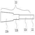
클립 본체(110)는 기단부(111), 양팔부(113) 및 협지부(115) 등으로 구성될 수 있다.
기단부(111)는 형광 표시 클립(100)의 사용 상태(도 9 및 도 10 참조)에서 생체 조직(미도시)과는 반대측에 위치하며, 후술하는 형광표시부(120)의 체결돌기(123a)와 착탈 가능하게 결합된다.The
본 실시예에서 기단부(111)는 대략 ㄷ자 형상의 단면을 가지는 구성을 예시하였으나, 이에 한정되지 않고 형광표시부(120)의 체결돌기(123a)와 체결될 수 있는 형상이면 충분하다.In the present exemplary embodiment, the
양팔부(113)는 기단부(111)의 양측으로부터 생체 조직 방향, 즉 전방으로 가늘고 길게 연장되어 형성된다.Both
양팔부(113)는 후술하는 생체 클립 조작 장치(10)의 조작 아암(또는 조작 와이어)(13)의 선단이 걸치되는 걸치부(113a)와, 걸치부(113a)의 후단에 걸치부(113a)의 판 폭 보다 작은 판 폭을 가지도록 단차 형성되고 후술하는 조임링(130)이 확실하게 걸려서 클립의 고정 및 조임 상태를 유지하는 단차부(113b)와, 기단부(111)와 단차부(113b) 사이에 내측으로 오목하게 형성되어 자기 확개성을 가지는 오목부(113c)로 구성될 수 있다. 여기서, 걸치부(113a)는 선단에서 후단으로 판 폭이 점점 작아지도록 테이퍼지게 형성되어 후술하는 조작 아암(13)의 체결 및 분리가 용이한 구조로 구성되는 것이 바람직하다.Both
협지부(115)는 생체 조직을 협지할 수 있도록 양팔부(113)의 선단을 내측으로 절곡하여 형성된다.The sandwiching
클립 본체(110)를 구성하는 기단부(111), 양팔부(113) 및 협지부(115)는 본 실시예에서 제시된 형상에 한정되지 않고 다양한 형상으로 제작될 수 있으며, 생체 조직을 클립핑하여 협지할 수 있는 자기 확개성 구조이면 충분하다.
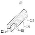
형광표시부(120)는 클립 본체(110)의 후단에 구비되는데, 도 1 및 도 2에 도시된 바와 같이, 형광표시부(120)가 클립 본체(110)에 착탈 가능하게 결합되거나, 도 3에 도시된 바와 같이, 형광표시부(120)가 클립 본체(110)에 일체형으로 형성될 수 있다.The
형광표시부(120)는 케이스(121) 및 체결부(123) 등으로 구성될 수 있다.The
케이스(121)는 내부에 소정 크기의 저장공간이 형성되고, 저장공간에 후술하는 광반응성 형광물질(122)이 저장된 후 기밀성 커버(미도시)에 의해 밀폐된다. 여 기서, 광반응성 형광물질(122)은 특정 파장 대역의 광원, 예컨대 인체에 무해한 레이저, LED 등과 같은 광원으로부터 빛이 조사됐을 때 스스로 빛을 발산하는 물질이다. 이러한 광반응성 형광물질(122)로는, 나노 크기의 반도체 입자(CdSe, CdTe, CdS, InAs 등)이 중심(core)을 이루는 형광 양자점(quantum dot)과 cyanine계열 형광 염료(Cy3, Cy5, Cy5.5, Cy7 등), BODIPY계열 형광 염료(BODIPY 639/650-X STP ester) 등의 다양한 형광 물질을 포함할 수 있다. 특히, 조사된 빛에 반응하여 근적외선 파장 영역대(600~900 nm 파장)에서 형광을 내는 형광 물질의 경우가 두꺼운 생체 조직에서의 형광 표지를 위하여 효율적으로 사용될 수 있으므로 본 발명의 사용에 특히 유용하다. 또한, 광반응성 형광물질(122)은 고체 또는 액체 형태일 수 있으며, 바람직하게는 액체 형태의 광반응성 형광물질(122)을 사용한다.The
이러한 광반응성 형광물질(122)은 일반적으로 인체에 유해한 성분을 함유하므로 케이스(121)는 기밀성을 확보하는 것이 바람직하다. 또한, 케이스(121)는 외부의 광원으로부터 빛이 최대한 투과되어 내부의 광반응성 형광물질(122)로 조사될 수 있도록 유리 또는 플라스틱 등과 같은 투명 재질 및 광투과성 재질로 제조되는 것이 바람직하다.Since the photoreactive
체결부(123)는 광반응성 형광물질(122)이 내장된 케이스(121)를 클립 본체(110)에 체결할 수 있도록 케이스(121)에 구비된다.The
체결부(123)는 케이스(121)의 선단 양측으로부터 전방으로 각각 연장되고 각각의 연장된 단부에 내측 방향으로 체결돌기(123a)가 형성되어 클립 본체(110)의 기단부(111)가 체결돌기(123a) 내에 삽입되어 체결될 수 있다. 여기서, 케이 스(121)의 체결부(123)와 클립 본체(110)의 기단부(111)의 체결을 용이하게 하면서 체결 후 케이스(121)의 이탈 방지를 위해 체결돌기(123a)의 선단은 내측으로 경사지게 형성되고 체결돌기(123a)의 후단은 수직하게 형성되는 것이 바람직하다. 본 실시예에서 체결부(123)는 체결돌기(123a) 형태를 가지는 구성을 예시하였으나, 이에 한정되지 않고 다양한 체결 구조의 선택이 가능하다. 예를 들어, 체결부(123)는 클립 본체(110)의 기단부(111)에 암나사(미도시)를 형성하고 케이스(121)의 선단에 수나사(미도시)를 형성하여 암사나와 나사 체결되는 구성도 가능하다.The
조임부(130)는 형광표시부(120)에 장착되는 위치로부터 클립 조작 장치(10)에 의해 가해지는 외력에 의해 클립 본체(110)로 슬라이드 이동되면서 클립 본체(110)의 선단 협지부(115)를 폐성(閉性)하도록 조여줌으로써 클립 본체(110)가 생체 조직을 클립핑(clipping)할 수 있다.The tightening
조임부(130)는 형광표시부(120)의 케이스(121)의 외경에 끼워져 슬라이드 이동 가능하도록 원통 형상의 조임링(이하, 참조부호 130으로 설명함)으로 구성될 수 있다.The tightening
조임링(130)은 외력에 의해 형광표시부(120)의 장착 위치로부터 클립 본체(110)로 슬라이드 이동되어 클립 본체(110)의 단차부(113b)에 걸려 안정적으로 장착될 수 있도록 형광표시부(120)의 케이스(121)의 외경과 클립 본체(110)의 기단부(111), 단차부(113b) 및 오목부(113c)의 판 폭 보다는 크고 클립 본체(110)의 걸치부(113a)의 판 폭 보다는 작은 내경을 가지는 것이 바람직하다. 또한, 조임링(130)은 클립 본체(110)의 단차부(113b) 길이에 대응되는 길이를 가지는 것이 바 람직하다.The
조임링(130)의 재질로는 특별히 제한되지 않으나, 클립 본체(110)와 함께 사용되기 때문에 클립 본체(110)와 동일한 재질로 제작될 수 있다. 예를 들어, 조임링(130)은 스테인리스 및 티탄합금 등의 금속, 또는 ABS수지, 경질염화비닐수지, 폴리아미드 및 폴리에틸렌 등의 플라스틱 재질로 제작되는 것이 바람직하다.The material of the tightening
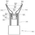
도 9 및 도 10은 본 발명의 형광 표시 클립의 사용 형태를 도시한 단면도로서, 도 9는 본 발명의 형광 표시 클립을 클립 조작 장치에 장착한 상태를 도시한 단면도이고, 도 10은 본 발명의 형광 표시 클립의 고정 및 조임 상태를 도시한 단면도이다.9 and 10 are cross-sectional views showing usage forms of the fluorescent display clip of the present invention, FIG. 9 is a cross-sectional view showing a state in which the fluorescent display clip of the present invention is attached to a clip operating device, and FIG. 10 is a cross-sectional view of the present invention. It is sectional drawing which shows the fixation and fastening state of a fluorescent display clip.
먼저, 도 9에 도시된 바와 같이, 본 발명의 형광 표시 클립(100)은 별도로 제작된 클립 조작 장치(10)의 선단부에 장착하여 사용한다. 예를 들어, 클립 조작 장치(10)의 조작 아암(13)의 선단에 형광 표시 클립(100)의 걸치부(113a)가 걸치되고 형광 표시 클립(100)의 기단부(111) 및 형광표시부(120)가 클립 조작 장치(10)의 내강(11)에 진퇴 이동 가능하게 삽입되어 장착될 수 있다. 여기서, 클립 조작 장치(10)는 광반응성 형광물질(122)이 내장된 형광 표시 클립(100)을 장착하여 환자의 생체 조직 내 목적 위치로 이송 및 고정시키기 위한 장치이다. 이러한 클립 조작 장치(10)는 공지된 기술로 이해 가능하므로 상세한 설명은 생략한다.First, as shown in FIG. 9, the
다음으로, 도 10에 도시된 바와 같이, 먼저, 클립 조작 장치(10)의 선단부에 장착된 형광 표시 클립(100)을 대장, 위 등과 같은 생체 조직 내 목적 부위로 이송시킨다. 클립 조작 장치(10)에 의해 형광 표시 클립(100)이 목적 위치에 도달한 상 태에서 클립 조작 장치(10)의 조작 아암(13)을 후방으로 잡아 당겨 형광 표시 클립(100)의 걸치부(113a)를 닫아 형광 표시 클립(100)을 목적 위치에 고정시킨다. 또한, 조작 아암(13)을 잡아 당김으로써 클립 본체(110)의 양팔부(113)는 기단부(111)측으로부터 조임링(130)의 내경에 서서히 인입되고, 조임링(130)이 클립 본체(110)의 단차부(113b)의 위치까지 인입되면 조임링(130)이 단차부(113b)에 걸려 멈추게 되고, 클립 본체(110) 선단의 협지부(115)가 접촉하여 도시하지 않는 생체 조직을 협지한다. 이때, 폐성 상태에 있는 클립 본체(110)는 조임링(130)이 단차부(113b)에 걸려 확실하게 고정되기 때문에 클립 본체(110)는 협지해야 하는 생체 조직의 크기에 관계없이 장기간에 걸쳐 생체 조직을 협지한 상태를 유지할 수 있다.Next, as shown in FIG. 10, first, the
마지막으로, 형광 표시 클립(100)의 고정 및 조임이 종료되면, 조작 아암(13)을 걸치부(113a)로부터 분리시키고 클립 조작 장치(10)를 신체 외부로 뽑아내어 광반응성 형광물질(122)이 내장된 형광 표시 클립(100)만 생체 조직 내의 목적 부위에 남긴다.Finally, when the fixing and tightening of the
이와 같이, 클립 본체(110)의 후단에 광반응성 형광물질(122)이 내장된 형광표시부(120)를 결합함으로써, 생체 조직의 수술 부위에 클립핑하여 고정한 후 외부로부터 특정 파장 대역을 가지는 광원(미도시)을 조사하면 광반응성 형광물질(122)이 빛을 발산함으로써 신체 내 형광 표시 클립(100)의 정확한 위치를 쉽고 빠르게 찾을 수 있다.As such, by combining the
따라서, 본 발명의 형광 표시 클립(100)을 사용할 경우, 대장암, 위암 등의 치료 시술 시 절개 영역을 최소화하여 치료 효과를 높일 수 있고, 과도한 절개로 인한 부작용을 최소화할 수 있다. 또한, 본 발명의 형광 표시 클립(100)은 위암 및 대장암 시술 외에도 다양한 외과 시술 시 원하는 부위를 쉽고 빠르게 찾아낼 수 있는 위치표시자로서 그 적용 가능 분야가 매우 넓다. 또한, 클립 본체(110)에 추가된 광반응성 형광물질(122)의 위치 파악을 위해 인체에 무해한 레이저, LED 등과 같은 광원을 사용하므로 시술 시 환자에 미치는 영향이 거의 없고, 클립 조작 장치(10) 및 광원 장치(미도시)의 소형화를 통해 기존의 복강경 수술에도 그대로 적용이 가능하다.Therefore, when the
이상 첨부된 도면을 참조하여 본 발명의 실시 예를 설명하였지만, 본 발명이 속하는 기술분야에서 통상의 지식을 가진 자는 본 발명이 그 기술적 사상이나 필수적인 특징을 변경하지 않고서 다른 구체적인 형태로 실시될 수 있다는 것을 이해할 수 있을 것이다. 그러므로 이상에서 기술한 실시 예들은 모든 면에서 예시적인 것이며 한정적이 아닌 것으로 이해해야만 한다. 본 발명의 범위는 상기 상세한 설명보다는 후술하는 특허청구범위에 의하여 나타내어지며, 특허청구범위의 의미 및 범위 그리고 그 균등 개념으로부터 도출되는 모든 변경 또는 변형된 형태가 본 발명의 범위에 포함되는 것으로 해석되어야 한다.Although embodiments of the present invention have been described above with reference to the accompanying drawings, those skilled in the art to which the present invention pertains may implement the present invention in other specific forms without changing the technical spirit or essential features thereof. I can understand that. It is therefore to be understood that the above-described embodiments are illustrative in all aspects and not restrictive. The scope of the present invention is shown by the following claims rather than the above description, and all changes or modifications derived from the meaning and scope of the claims and their equivalents should be construed as being included in the scope of the present invention. do.
도 1 및 도 2는 본 발명의 바람직한 실시예에 따른 수술용 형광 표시 클립의 사시도이다.1 and 2 are perspective views of a surgical fluorescent display clip according to a preferred embodiment of the present invention.
도 3은 클립 본체와 형광표시부가 일체형 구조를 가지는 형광 표시 클립을 도시한 사시도이다.3 is a perspective view illustrating a fluorescent display clip having an integrated structure of a clip body and a fluorescent display unit.
도 4는 클립 본체의 사시도이다.4 is a perspective view of the clip body.
도 5는 클립 본체의 측면도이다.5 is a side view of the clip body.
도 6 및 도 7은 클립 본체 자체에 형광물질이 포함되는 일 예를 도시한 예시도이다.6 and 7 are exemplary views illustrating an example in which a fluorescent material is included in the clip body itself.
도 8은 형광표시부의 사시도이다.8 is a perspective view of the fluorescent display unit.
도 9 및 도 10은 본 발명의 형광 표시 클립의 사용 형태를 도시한 단면도이다.9 and 10 are cross-sectional views showing usage forms of the fluorescent display clip of the present invention.
< 도면의 주요 부분에 대한 부호의 설명 >Description of the Related Art
100 : 형광 표시 클립 110 : 클립 본체100: fluorescent display clip 110: clip body
111 : 기단부 113 : 양팔부111: proximal end 113: both arms
113a : 걸치부 113b : 단차부113a:
113c : 오목부 115 : 협지부113c:
120 : 형광표시부 121 : 케이스120: fluorescent display 121: case
122 : 형광물질 123 : 체결부122: fluorescent material 123: fastening portion
130 : 조임부(조임링)130: tightening part (fastening ring)
Claims (13)
Translated fromKoreanPriority Applications (5)
| Application Number | Priority Date | Filing Date | Title |
|---|---|---|---|
| KR1020090058067AKR101263937B1 (en) | 2009-06-29 | 2009-06-29 | Fluorescent indication clip for surgery |
| JP2009235471AJP5107328B2 (en) | 2009-06-29 | 2009-10-09 | Fluorescent display clip for surgery |
| US12/612,305US8688195B2 (en) | 2009-06-29 | 2009-11-04 | Fluorescent indication clip for surgery |
| EP10153203.4AEP2269518B1 (en) | 2009-06-29 | 2010-02-10 | Fluorescent indication clip for surgery |
| CN2010102180208ACN101933835B (en) | 2009-06-29 | 2010-06-28 | Fluorescent display clip for operation |
Applications Claiming Priority (1)
| Application Number | Priority Date | Filing Date | Title |
|---|---|---|---|
| KR1020090058067AKR101263937B1 (en) | 2009-06-29 | 2009-06-29 | Fluorescent indication clip for surgery |
Related Child Applications (1)
| Application Number | Title | Priority Date | Filing Date |
|---|---|---|---|
| KR1020110128119ADivisionKR101263939B1 (en) | 2011-12-02 | 2011-12-02 | Fluorescent indication clip for surgery |
Publications (2)
| Publication Number | Publication Date |
|---|---|
| KR20110000796A KR20110000796A (en) | 2011-01-06 |
| KR101263937B1true KR101263937B1 (en) | 2013-05-13 |
Family
ID=42782040
Family Applications (1)
| Application Number | Title | Priority Date | Filing Date |
|---|---|---|---|
| KR1020090058067AActiveKR101263937B1 (en) | 2009-06-29 | 2009-06-29 | Fluorescent indication clip for surgery |
Country Status (5)
| Country | Link |
|---|---|
| US (1) | US8688195B2 (en) |
| EP (1) | EP2269518B1 (en) |
| JP (1) | JP5107328B2 (en) |
| KR (1) | KR101263937B1 (en) |
| CN (1) | CN101933835B (en) |
Cited By (2)
| Publication number | Priority date | Publication date | Assignee | Title |
|---|---|---|---|---|
| WO2022235479A1 (en)* | 2021-05-04 | 2022-11-10 | Boehringer Technologies, Lp | Gastric sizing systems including illuminating devices and methods of bariatric surgery using the same |
| KR20250059578A (en) | 2023-10-24 | 2025-05-07 | 주식회사 코스코인터케어 | Method of Manufacturing Photo-Reactive Coating Agent, Medical Marker Including Photo-Reactive Coating Agent Manufactured by the Method, and Method of Manufacturing the Medical Marker |
Families Citing this family (18)
| Publication number | Priority date | Publication date | Assignee | Title |
|---|---|---|---|---|
| KR101163630B1 (en)* | 2011-01-25 | 2012-07-09 | 신경민 | Surgical Position Check Luminescent Capsule |
| JP6052010B2 (en)* | 2013-03-28 | 2016-12-27 | 住友ベークライト株式会社 | Biological tissue clip device |
| WO2015182737A1 (en)* | 2014-05-29 | 2015-12-03 | 国立大学法人 高知大学 | Living body pressing clip |
| WO2016063679A1 (en)* | 2014-10-24 | 2016-04-28 | 株式会社カネカ | Clip device for endoscope and method for mounting clip for implanting in body |
| KR101684781B1 (en)* | 2015-05-11 | 2016-12-08 | 고려대학교 산학협력단 | X-ray imaging apparatus for minimally invasive surgery |
| JP6694893B2 (en)* | 2015-10-23 | 2020-05-20 | 株式会社カネカ | Medical clip |
| JP6632930B2 (en)* | 2016-04-11 | 2020-01-22 | 野村ユニソン株式会社 | Clip unit for ligating device and method of engaging the clip unit |
| KR102016960B1 (en)* | 2017-11-13 | 2019-09-02 | 재단법인 오송첨단의료산업진흥재단 | Attachable clip module using rfid for detecting a portion |
| JP7087582B2 (en)* | 2018-03-30 | 2022-06-21 | 日本ゼオン株式会社 | In-vivo indwelling clip |
| CN118717215A (en)* | 2018-03-30 | 2024-10-01 | 日本瑞翁株式会社 | In-vivo clamp |
| EP3777718B1 (en)* | 2018-03-30 | 2025-03-05 | Zeon Corporation | Indwelling clip |
| JP6647648B1 (en) | 2019-08-19 | 2020-02-14 | 国立大学法人高知大学 | Opening and closing clip |
| CN112690864B (en)* | 2019-10-23 | 2022-03-22 | 苏州英途康医疗科技有限公司 | Medical instrument and automatic clamp feeding method |
| WO2021100379A1 (en)* | 2019-11-19 | 2021-05-27 | 株式会社カネカ | Endoscope clip system |
| WO2021100378A1 (en)* | 2019-11-19 | 2021-05-27 | 株式会社カネカ | Endoscope clip system and method for producing same |
| JP6675674B1 (en)* | 2019-12-25 | 2020-04-01 | 国立大学法人高知大学 | Opening and closing clip |
| JP7190719B2 (en)* | 2020-11-30 | 2022-12-16 | 国立大学法人高知大学 | biological compression clip |
| KR20240166655A (en)* | 2023-05-18 | 2024-11-26 | 연세대학교 산학협력단 | System for marking lesion location |
Citations (1)
| Publication number | Priority date | Publication date | Assignee | Title |
|---|---|---|---|---|
| US20080009886A1 (en) | 2006-07-05 | 2008-01-10 | Wilson-Cook Medical Inc. | Suction cup |
Family Cites Families (8)
| Publication number | Priority date | Publication date | Assignee | Title |
|---|---|---|---|---|
| JPH0327808U (en)* | 1989-07-28 | 1991-03-20 | ||
| JP3568280B2 (en)* | 1995-07-12 | 2004-09-22 | 富士写真フイルム株式会社 | Surgical operation support system |
| JP3027808U (en)* | 1996-02-09 | 1996-08-20 | 尚則 松岡 | Glowing marking clip |
| AU2001288945A1 (en)* | 2000-09-07 | 2002-03-22 | Eva Arkin | Fluorescent surgical device |
| WO2003053256A1 (en)* | 2001-12-13 | 2003-07-03 | Sumitomo Bakelite Company Limited | Clip device for endoscope and clip for endoscope for use therein |
| WO2004082488A1 (en)* | 2003-03-17 | 2004-09-30 | Sumitomo Bakelite Company Limited | Clip and clipping instrument for biological tissues |
| JP4578817B2 (en)* | 2004-02-06 | 2010-11-10 | オリンパス株式会社 | Surgical lesion identification system |
| US20060247678A1 (en)* | 2005-04-08 | 2006-11-02 | Weisenburgh William B Ii | Surgical instrument system |
- 2009
- 2009-06-29KRKR1020090058067Apatent/KR101263937B1/enactiveActive
- 2009-10-09JPJP2009235471Apatent/JP5107328B2/enactiveActive
- 2009-11-04USUS12/612,305patent/US8688195B2/enactiveActive
- 2010
- 2010-02-10EPEP10153203.4Apatent/EP2269518B1/enactiveActive
- 2010-06-28CNCN2010102180208Apatent/CN101933835B/enactiveActive
Patent Citations (1)
| Publication number | Priority date | Publication date | Assignee | Title |
|---|---|---|---|---|
| US20080009886A1 (en) | 2006-07-05 | 2008-01-10 | Wilson-Cook Medical Inc. | Suction cup |
Non-Patent Citations (1)
| Title |
|---|
| 논문 1: 대한방사선 종양학회지* |
Cited By (3)
| Publication number | Priority date | Publication date | Assignee | Title |
|---|---|---|---|---|
| WO2022235479A1 (en)* | 2021-05-04 | 2022-11-10 | Boehringer Technologies, Lp | Gastric sizing systems including illuminating devices and methods of bariatric surgery using the same |
| KR20250059578A (en) | 2023-10-24 | 2025-05-07 | 주식회사 코스코인터케어 | Method of Manufacturing Photo-Reactive Coating Agent, Medical Marker Including Photo-Reactive Coating Agent Manufactured by the Method, and Method of Manufacturing the Medical Marker |
| KR20250061702A (en) | 2023-10-24 | 2025-05-08 | 주식회사 코스코인터케어 | Method of Manufacturing Photo-Reactive Coating Agent, Medical Marker Including Photo-Reactive Coating Agent Manufactured by the Method, and Method of Manufacturing the Medical Marker |
Also Published As
| Publication number | Publication date |
|---|---|
| EP2269518B1 (en) | 2016-05-11 |
| EP2269518A2 (en) | 2011-01-05 |
| KR20110000796A (en) | 2011-01-06 |
| US8688195B2 (en) | 2014-04-01 |
| CN101933835A (en) | 2011-01-05 |
| JP2011005227A (en) | 2011-01-13 |
| US20100331674A1 (en) | 2010-12-30 |
| JP5107328B2 (en) | 2012-12-26 |
| CN101933835B (en) | 2013-06-12 |
| EP2269518A3 (en) | 2011-12-28 |
Similar Documents
| Publication | Publication Date | Title |
|---|---|---|
| KR101263937B1 (en) | Fluorescent indication clip for surgery | |
| US12310559B2 (en) | Instrument port with integrated imaging system | |
| KR101159422B1 (en) | Surgical indicator clip and clip apparatus | |
| AU2008205334B2 (en) | Access sheath with removable optical penetrating member | |
| US6142931A (en) | Guide tube unit for endoscope and method for resecting a tissue | |
| ES2626329T3 (en) | Operation device specially designed to perform an operation inside the body of a living being | |
| ES2983728T3 (en) | Steerable ultrasound coupling for endoscope | |
| JP2011104366A (en) | Access device including integrated light source | |
| JPH03500971A (en) | Compound catheter and body lumen tissue clamping device and method thereof | |
| KR101263939B1 (en) | Fluorescent indication clip for surgery | |
| KR102629368B1 (en) | Treatment substance transport device and treatment substance transport kit | |
| US8915836B2 (en) | Endoscope, guide unit, guide wire, medical-device guiding system, and medical-device guiding method | |
| US20170020629A1 (en) | Marking system | |
| JP7388133B2 (en) | medical marker | |
| KR101876807B1 (en) | Photo dynamics apparatus for medical treatment or needle | |
| JP2018535738A (en) | Endoscopic cap with deflection channel for endoscopic treatment | |
| JP2023100118A (en) | medical clip | |
| WO2021009835A1 (en) | Treatment tool for endoscope | |
| KR102045383B1 (en) | Overtube | |
| Jang | Future development of endoscopic accessories for endoscopic submucosal dissection | |
| KR20220166741A (en) | Endoscope surgery path secure equipment | |
| CN210354853U (en) | a puncture device | |
| KR20240084391A (en) | Scope of Endoscope lens cover attachment device | |
| US20250057629A1 (en) | Slip-on Sleeve or Clip Attached to Medical Instruments to Provide Visualization | |
| KR20240166655A (en) | System for marking lesion location |
Legal Events
| Date | Code | Title | Description |
|---|---|---|---|
| A201 | Request for examination | ||
| PA0109 | Patent application | Patent event code:PA01091R01D Comment text:Patent Application Patent event date:20090629 | |
| PA0201 | Request for examination | ||
| PG1501 | Laying open of application | ||
| E902 | Notification of reason for refusal | ||
| PE0902 | Notice of grounds for rejection | Comment text:Notification of reason for refusal Patent event date:20110323 Patent event code:PE09021S01D | |
| AMND | Amendment | ||
| E601 | Decision to refuse application | ||
| PE0601 | Decision on rejection of patent | Patent event date:20110929 Comment text:Decision to Refuse Application Patent event code:PE06012S01D Patent event date:20110323 Comment text:Notification of reason for refusal Patent event code:PE06011S01I | |
| AMND | Amendment | ||
| J201 | Request for trial against refusal decision | ||
| PJ0201 | Trial against decision of rejection | Patent event date:20111124 Comment text:Request for Trial against Decision on Refusal Patent event code:PJ02012R01D Patent event date:20110929 Comment text:Decision to Refuse Application Patent event code:PJ02011S01I Appeal kind category:Appeal against decision to decline refusal Decision date:20130225 Appeal identifier:2011101008998 Request date:20111124 | |
| A107 | Divisional application of patent | ||
| PA0107 | Divisional application | Comment text:Divisional Application of Patent Patent event date:20111202 Patent event code:PA01071R01D | |
| PB0901 | Examination by re-examination before a trial | Comment text:Amendment to Specification, etc. Patent event date:20111124 Patent event code:PB09011R02I Comment text:Request for Trial against Decision on Refusal Patent event date:20111124 Patent event code:PB09011R01I Comment text:Amendment to Specification, etc. Patent event date:20110518 Patent event code:PB09011R02I | |
| B601 | Maintenance of original decision after re-examination before a trial | ||
| PB0601 | Maintenance of original decision after re-examination before a trial | Comment text:Report of Result of Re-examination before a Trial Patent event code:PB06011S01D Patent event date:20120111 | |
| J301 | Trial decision | Free format text:TRIAL DECISION FOR APPEAL AGAINST DECISION TO DECLINE REFUSAL REQUESTED 20111124 Effective date:20130225 | |
| PJ1301 | Trial decision | Patent event code:PJ13011S01D Patent event date:20130226 Comment text:Trial Decision on Objection to Decision on Refusal Appeal kind category:Appeal against decision to decline refusal Request date:20111124 Decision date:20130225 Appeal identifier:2011101008998 | |
| PS0901 | Examination by remand of revocation | ||
| S901 | Examination by remand of revocation | ||
| GRNO | Decision to grant (after opposition) | ||
| PS0701 | Decision of registration after remand of revocation | Patent event date:20130312 Patent event code:PS07012S01D Comment text:Decision to Grant Registration Patent event date:20130227 Patent event code:PS07011S01I Comment text:Notice of Trial Decision (Remand of Revocation) | |
| GRNT | Written decision to grant | ||
| PR0701 | Registration of establishment | Comment text:Registration of Establishment Patent event date:20130507 Patent event code:PR07011E01D | |
| PR1002 | Payment of registration fee | Payment date:20130508 End annual number:3 Start annual number:1 | |
| PG1601 | Publication of registration | ||
| FPAY | Annual fee payment | Payment date:20160422 Year of fee payment:4 | |
| PR1001 | Payment of annual fee | Payment date:20160422 Start annual number:4 End annual number:4 | |
| FPAY | Annual fee payment | Payment date:20170224 Year of fee payment:5 | |
| PR1001 | Payment of annual fee | Payment date:20170224 Start annual number:5 End annual number:5 | |
| FPAY | Annual fee payment | Payment date:20180410 Year of fee payment:6 | |
| PR1001 | Payment of annual fee | Payment date:20180410 Start annual number:6 End annual number:6 | |
| FPAY | Annual fee payment | Payment date:20190326 Year of fee payment:7 | |
| PR1001 | Payment of annual fee | Payment date:20190326 Start annual number:7 End annual number:7 | |
| FPAY | Annual fee payment | Payment date:20200313 Year of fee payment:8 | |
| PR1001 | Payment of annual fee | Payment date:20200313 Start annual number:8 End annual number:8 | |
| PR1001 | Payment of annual fee | Payment date:20220310 Start annual number:10 End annual number:10 | |
| PR1001 | Payment of annual fee | Payment date:20240409 Start annual number:12 End annual number:12 |