KR101262968B1 - Unmanned Aerial System Including Unmanned Aerial Vehicle Having Spherical Loading Portion And Unmanned Ground Vehicle Therefor - Google Patents
Unmanned Aerial System Including Unmanned Aerial Vehicle Having Spherical Loading Portion And Unmanned Ground Vehicle ThereforDownload PDFInfo
- Publication number
- KR101262968B1 KR101262968B1KR1020090082687AKR20090082687AKR101262968B1KR 101262968 B1KR101262968 B1KR 101262968B1KR 1020090082687 AKR1020090082687 AKR 1020090082687AKR 20090082687 AKR20090082687 AKR 20090082687AKR 101262968 B1KR101262968 B1KR 101262968B1
- Authority
- KR
- South Korea
- Prior art keywords
- unmanned aerial
- aerial vehicle
- landing
- unmanned
- vehicle
- Prior art date
- Legal status (The legal status is an assumption and is not a legal conclusion. Google has not performed a legal analysis and makes no representation as to the accuracy of the status listed.)
- Expired - Fee Related
Links
Images


Classifications
- B—PERFORMING OPERATIONS; TRANSPORTING
- B64—AIRCRAFT; AVIATION; COSMONAUTICS
- B64C—AEROPLANES; HELICOPTERS
- B64C13/00—Control systems or transmitting systems for actuating flying-control surfaces, lift-increasing flaps, air brakes, or spoilers
- B64C13/02—Initiating means
- B64C13/16—Initiating means actuated automatically, e.g. responsive to gust detectors
- B64C13/20—Initiating means actuated automatically, e.g. responsive to gust detectors using radiated signals
- B—PERFORMING OPERATIONS; TRANSPORTING
- B64—AIRCRAFT; AVIATION; COSMONAUTICS
- B64C—AEROPLANES; HELICOPTERS
- B64C39/00—Aircraft not otherwise provided for
- B64C39/02—Aircraft not otherwise provided for characterised by special use
- B—PERFORMING OPERATIONS; TRANSPORTING
- B64—AIRCRAFT; AVIATION; COSMONAUTICS
- B64F—GROUND OR AIRCRAFT-CARRIER-DECK INSTALLATIONS SPECIALLY ADAPTED FOR USE IN CONNECTION WITH AIRCRAFT; DESIGNING, MANUFACTURING, ASSEMBLING, CLEANING, MAINTAINING OR REPAIRING AIRCRAFT, NOT OTHERWISE PROVIDED FOR; HANDLING, TRANSPORTING, TESTING OR INSPECTING AIRCRAFT COMPONENTS, NOT OTHERWISE PROVIDED FOR
- B64F1/00—Ground or aircraft-carrier-deck installations
- B64F1/04—Ground or aircraft-carrier-deck installations for launching aircraft
- B—PERFORMING OPERATIONS; TRANSPORTING
- B64—AIRCRAFT; AVIATION; COSMONAUTICS
- B64U—UNMANNED AERIAL VEHICLES [UAV]; EQUIPMENT THEREFOR
- B64U70/00—Launching, take-off or landing arrangements
- B64U70/90—Launching from or landing on platforms
- B64U70/97—Means for guiding the UAV to a specific location on the platform, e.g. platform structures preventing landing off-centre
- B—PERFORMING OPERATIONS; TRANSPORTING
- B64—AIRCRAFT; AVIATION; COSMONAUTICS
- B64U—UNMANNED AERIAL VEHICLES [UAV]; EQUIPMENT THEREFOR
- B64U80/00—Transport or storage specially adapted for UAVs
- B64U80/20—Transport or storage specially adapted for UAVs with arrangements for servicing the UAV
- B64U80/25—Transport or storage specially adapted for UAVs with arrangements for servicing the UAV for recharging batteries; for refuelling
- B—PERFORMING OPERATIONS; TRANSPORTING
- B64—AIRCRAFT; AVIATION; COSMONAUTICS
- B64U—UNMANNED AERIAL VEHICLES [UAV]; EQUIPMENT THEREFOR
- B64U80/00—Transport or storage specially adapted for UAVs
- B64U80/80—Transport or storage specially adapted for UAVs by vehicles
- B64U80/86—Land vehicles
- B—PERFORMING OPERATIONS; TRANSPORTING
- B64—AIRCRAFT; AVIATION; COSMONAUTICS
- B64U—UNMANNED AERIAL VEHICLES [UAV]; EQUIPMENT THEREFOR
- B64U10/00—Type of UAV
- B64U10/10—Rotorcrafts
- B64U10/13—Flying platforms
- B—PERFORMING OPERATIONS; TRANSPORTING
- B64—AIRCRAFT; AVIATION; COSMONAUTICS
- B64U—UNMANNED AERIAL VEHICLES [UAV]; EQUIPMENT THEREFOR
- B64U20/00—Constructional aspects of UAVs
- B64U20/50—Foldable or collapsible UAVs
- B—PERFORMING OPERATIONS; TRANSPORTING
- B64—AIRCRAFT; AVIATION; COSMONAUTICS
- B64U—UNMANNED AERIAL VEHICLES [UAV]; EQUIPMENT THEREFOR
- B64U30/00—Means for producing lift; Empennages; Arrangements thereof
- B64U30/20—Rotors; Rotor supports
- B64U30/24—Coaxial rotors
- B—PERFORMING OPERATIONS; TRANSPORTING
- B64—AIRCRAFT; AVIATION; COSMONAUTICS
- B64U—UNMANNED AERIAL VEHICLES [UAV]; EQUIPMENT THEREFOR
- B64U70/00—Launching, take-off or landing arrangements
- B64U70/30—Launching, take-off or landing arrangements for capturing UAVs in flight by ground or sea-based arresting gear, e.g. by a cable or a net
Landscapes
- Engineering & Computer Science (AREA)
- Aviation & Aerospace Engineering (AREA)
- Remote Sensing (AREA)
- Transportation (AREA)
- Mechanical Engineering (AREA)
- Automation & Control Theory (AREA)
- Control Of Position, Course, Altitude, Or Attitude Of Moving Bodies (AREA)
Abstract
Translated fromKoreanDescription
Translated fromKorean본 발명은 무인항공기 및 무인항공기 탑재를 위한 무인지상차량에 관한 것이다. 보다 구체적으로, 무인지상차량의 수평여부에 상관없이 용이한 이착륙이 가능한 무인항공기 및 무인항공기 탑재를 위한 무인지상차량에 관한 것이다.The present invention relates to an unmanned aerial vehicle and an unmanned aerial vehicle for mounting an unmanned aerial vehicle. More specifically, the present invention relates to an unmanned aerial vehicle and an unmanned aerial vehicle for mounting an unmanned aerial vehicle capable of easy takeoff and landing regardless of whether the unmanned aerial vehicle is horizontal.
무인항공기(UAV: Unmanned Aerial Vehicle) 및 무인지상차량(UGV: Unmanned Ground Vehicle)은 사람이 탑승하지 않은 상태에서 탑재된 온보드 컴퓨터에 의해 그 자세 및 위치를 자동으로 제어될 수 있고 원격통제소의 명령에 의해 원하는 위치로 이동할 수 있는 플랫폼으로서 감시 정찰 분야를 중심으로 다양한 형태와 크기의 제품이 개발되고 있다.Unmanned Aerial Vehicles (UAVs) and Unmanned Ground Vehicles (UGVs) can be controlled automatically by their onboard computer without a person on board and at the command of a remote control station. As a platform that can be moved to a desired location, products of various shapes and sizes are being developed around the surveillance reconnaissance field.
무인항공기는 그 형태에 따라 고정날개형과 회전날개형 무인항공기로 분류할 수 있다. 이 중 회전날개형 무인항공기는 고정날개형 무인항공기에 비해, 정지비행 및 수직이착륙이 가능하여 활주로가 없는 상황에서도 임무를 수행할 수 있고, 장애물과 같은 지형의 영향을 덜 받고 관심 있는 목표물에 근접하여 정찰할 수 있어 근거리에서 감시 정찰을 수행할 수 있는 이점이 있으며, 특히 상하 두 개의 메인로터로 구성되는 동축반전형 헬리콥터의 경우 꼬리로터가 없는 관계로 형상을 단순화 할 수 있어, 감시정찰용 무인항공기의 형상으로 적합하다.Unmanned aerial vehicles may be classified into fixed wing and rotary wing unmanned aerial vehicles according to their type. Among them, rotary wing type UAVs are capable of stationary flight and vertical takeoff and landing, compared to fixed wing type UAVs, allowing them to perform missions even in the absence of runways, and are less affected by terrain such as obstacles and closer to targets of interest. It can be used for surveillance reconnaissance at close range, and especially in the case of coaxial reversal helicopter consisting of two main rotors, the shape can be simplified because there is no tail rotor. Suitable for the shape of the aircraft.
그러나 회전날개형 무인항공기는 소모동력이 크기 때문에, 동일한 이륙중량일 때 적게는 2~3배 많게는 10배의 체공시간을 갖는 고정날개형 무인항공기에 비해 체공시간에 제한이 있는 단점이 있다.However, due to the large power consumption of the rotary wing type unmanned aerial vehicle, there is a disadvantage in that the flight time is limited compared to the fixed wing type unmanned aerial vehicle having a flight time of 2 to 3 times as much as 10 times at the same takeoff weight.
한편, 무인지상차량은 탑재중량이나 주행시간의 한계는 덜한 반면 지형이나 장애물에 의해 주행 가능한 범위가 제한되고 이로 인해 감시 정찰 정보 역시 제한적일 수밖에 없다.On the other hand, while the unmanned vehicle has a lower limit of payload or travel time, the range that can be driven by terrain or obstacles is limited, and thus surveillance and reconnaissance information is also limited.
이와 같은 이유로 회전날개형 무인항공기와 무인지상차량을 통합하는 기술(UAV-UGV Teaming Operation)의 개발이 이루어지고 있다. 즉, 수직이착륙이 가능한 소형 무인항공기를 무인지상차량에 탑재하여 이동하는 개념으로, 탑재된 무인항공기는 무인지상차량에 의해 동력을 재충전하고, 무인지상차량의 감시 정찰이 불가능한 영역은 무인항공기가 담당함으로써 서로의 장단점을 상호 보완할 수 있는 것이다.For this reason, the development of the UAV-UGV Teaming Operation, which integrates a rotary wingless unmanned aerial vehicle and an unmanned aerial vehicle, is being conducted. In other words, a small unmanned aerial vehicle capable of vertical take-off and landing is mounted on an unmanned vehicle and moved.The mounted unmanned aerial vehicle recharges its power by an unmanned aerial vehicle, and the unmanned aerial vehicle is in charge of an area where surveillance and reconnaissance of the unmanned vehicle is impossible. By doing so, they can complement each other's advantages and disadvantages.
그런데, 험지를 주행하는 무인지상차량의 특성상 탑재된 무인항공기가 이착륙을 시도할 경우 무인항공기가 평형상태를 유지하는 경우가 드물고 이로 인해 원활한 이착륙이 어렵다. 무인항공기가 무인지상차량으로부터 동력을 재충전받기 위 해서는 무인지상차량의 전원공급부에 무인항공기의 커플러가 아주 정밀하게 동일한 위치에 착륙되어야 하는 어려움이 있다.However, when an unmanned aerial vehicle mounted on a rough terrain attempts to take off and land, the unmanned aerial vehicle rarely maintains an equilibrium state, and thus smooth landing and landing are difficult. In order for an unmanned aerial vehicle to be recharged from an unmanned aerial vehicle, there is a difficulty that the coupler of the unmanned aerial vehicle must land at the same position with high precision.
상기와 같은 문제점을 해결하기 위해 무인항공기의 이착륙시 무인지상차량을 평형상태로 맞추는 레벨링 장치를 무인지상차량에 부착하는 연구가 시도되고 있다. 그러나 이러한 레벨링 장치는 이착륙만을 위한 부가 장치로 시스템의 무게와 복잡도를 증가시키는 요인이 되었다.In order to solve the above problems, a research has been attempted to attach the leveling device to the unmanned vehicle to balance the unmanned vehicle at the time of takeoff and landing of the unmanned aerial vehicle. However, this leveling device is an additional device for takeoff and landing only, which increases the weight and complexity of the system.
따라서 시스템의 무게와 복잡도를 증가시키지 않으면서도 지상무인차량의 평형상태에 무관하게 무인항공기가 용이하게 이착륙할 수 있는 새로운 해결방안이 필요하다. 이에 본 발명자는 새로운 구조를 갖는 본 발명에 따른 무인항공기 및 무인지상차량을 개발하기에 이른 것이다.Thus, there is a need for a new solution that allows an unmanned aerial vehicle to easily take off and land without increasing the weight and complexity of the system. Accordingly, the present inventors have come to develop an unmanned aerial vehicle and an unmanned aerial vehicle according to the present invention having a new structure.
본 발명의 목적은 무인항공기 및 무인항공기 탑재를 위한 무인지상차량을 제공하기 위한 것이다.An object of the present invention is to provide an unmanned aerial vehicle and an unmanned aerial vehicle for mounting the unmanned aerial vehicle.
본 발명의 다른 목적은 무인지상차량의 수평여부에 상관없이 무인항공기가 용이하게 이착륙할 수 있도록 하는 것이다.Another object of the present invention is to enable the unmanned aerial vehicle to easily take off and land regardless of whether the unmanned aerial vehicle is horizontal.
본 발명의 또 다른 목적은 단독 착륙할 수 있는 무인항공기를 제공하기 위한 것이다.Another object of the present invention is to provide an unmanned aerial vehicle capable of landing solely.
본 발명의 또 다른 목적은 무인항공기의 전원을 재충전할 수 있도록 하는 것이다.Another object of the present invention is to be able to recharge the power of the unmanned aerial vehicle.
본 발명의 또 다른 목적은 착륙한 무인항공기를 안정적으로 고정할 수 있도록 하는 무인지상차량을 제공하는 것이다.Still another object of the present invention is to provide an unmanned vehicle that can stably land the unmanned aerial vehicle.
본 발명의 또 다른 목적은 무인항공기의 이착륙에 방해되지 않으면서 무인항공기를 고정할 수 있는 무인지상차량을 제공하는 것이다.Still another object of the present invention is to provide an unmanned aerial vehicle capable of fixing an unmanned aerial vehicle without interfering with the takeoff and landing of the unmanned aerial vehicle.
본 발명의 또 다른 목적은 착륙한 무인항공기를 원하는 위치로 이동시킬 수 있는 무인지상차량을 제공하기 위한 것이다.Still another object of the present invention is to provide an unmanned aerial vehicle capable of moving a landed unmanned aerial vehicle to a desired position.
본 발명의 또 다른 목적은 착륙한 무인항공기의 위치를 정밀 제어할 수 있는 무인지상차량을 제공하기 위한 것이다.Still another object of the present invention is to provide an autonomous vehicle capable of precisely controlling the position of the unmanned aerial vehicle that has landed.
본 발명의 또 다른 목적은 착륙후 무인항공기의 위치를 정밀 제어할 수 있어 착륙시 위치오차가 발생하더라도 항상 동일한 위치에 무인항공기를 정렬할 수 있는 무인지상차량을 제공하는 것이다.Still another object of the present invention is to provide an unmanned vehicle that can precisely control the position of the unmanned aerial vehicle after landing so that the unmanned aerial vehicle can always be aligned at the same position even if a position error occurs during landing.
본 발명의 또 다른 목적은 레벨링 장치가 필요없어 무게를 줄일 수 있는 무인지상차량을 제공하는 것이다.Still another object of the present invention is to provide an autonomous vehicle that can reduce weight by eliminating the need for a leveling device.
본 발명의 상기 및 기타의 목적들은 상세히 설명되는 본 발명에 의하여 모두 달성될 수 있다. 이하 본 발명의 내용을 하기에 상세히 설명한다.The above and other objects of the present invention can be achieved by the present invention described in detail. Hereinafter, the content of the present invention will be described in detail.
본 발명에 따른 무인항공기는 무인지상차량과의 결합 착륙을 위한 구형 탑재부를 구비하며, 무인지상차량은 무인항공기의 구형 탑재부 일부분이 삽입되어 결합 착륙하기 위한 랜딩부를 구비하여 무인지상차량의 수평 여부에 관계없이 무인항공기가 무인지상차량에 용이하게 이착륙할 수 있는 것을 특징으로 한다.The unmanned aerial vehicle according to the present invention includes a spherical mounting portion for coupled landing with an unmanned aerial vehicle, and the unmanned aerial vehicle includes a landing portion for inserting and landing a coupled portion of the unmanned aerial vehicle so that the unmanned aerial vehicle is horizontal or not. Regardless, it can be easily taken off and landed on an unmanned aerial vehicle.
상기 무인항공기의 동체를 상기 구형 탑재부로 구성할 수 있다. 이로써, 무인항공기의 구조를 단순화하고 경량화할 수 있다. 또한, 상기 랜딩부를 상기 구형 탑재부의 일부분에 대응하는 반구형으로 구성할 수 있다.The body of the unmanned aerial vehicle may be configured as the spherical mounting portion. As a result, the structure of the unmanned aerial vehicle can be simplified and reduced in weight. In addition, the landing portion may be configured as a hemispherical shape corresponding to a portion of the spherical mounting portion.
상기 무인항공기는 접이식 강착부를 더 포함하여 단독 착륙 가능하게 구성할 수 있다.The unmanned aerial vehicle may further include a folding accent part so as to be capable of landing alone.
상기 구형 탑재부에는 무인지상차량의 전원공급부에 접속하여 전원을 재충전하는 커플러가 구비되어 있고, 상기 랜딩부 내부에는 무인항공기 커플러와 결합하여 무인항공기 재충전을 위한 전원을 공급하는 전원공급부가 형성되어 무인항공기가 착륙한 동안 전원을 재충전할 수 있다.The spherical mounting portion is provided with a coupler for recharging the power by connecting to the power supply of the unmanned vehicle, and the landing portion is coupled to the unmanned aerial vehicle coupler is provided with a power supply for supplying power for recharging the unmanned aerial vehicle unmanned aerial vehicle Power can be recharged during the landing.
상기 무인지상차량에는 랜딩부에 결합 착륙한 무인항공기를 고정시키기 위한 구속장치를 더 포함할 수 있고, 이 구속장치는 무인항공기를 안정적으로 고정시키면서도 이착륙시 방해가 되지 않도록 무인항공기 착륙 위치에 가까워지는 방향 및 멀어지는 방향으로 이동 가능한 복수개의 링크암으로 이루어질 수 있다.The unmanned aerial vehicle may further include a restraining device for fixing the unmanned aerial vehicle coupled to and landing on the landing part, and the restraining device is stably fixed to the unmanned aerial vehicle, but is close to the unmanned aerial vehicle landing position so as not to be disturbed during takeoff and landing. It may be composed of a plurality of link arms movable in the direction and away.
상기 무인지상차량에는 착륙한 무인항공기를 원하는 위치로 이동시키기 위한 이동장치를 더 포함할 수 있고, 이 이동장치는 상기 무인항공기와 맞닿는 링크부의 말단에 위치한 구동휠로 구성할 수 있다.The unmanned aerial vehicle may further include a moving device for moving the landed unmanned aerial vehicle to a desired position, and the moving device may be configured as a driving wheel located at an end of a link portion in contact with the unmanned aerial vehicle.
상기 구동휠은 고도각 및 방위각을 정렬할 수 있는 방향으로 회전될 수 있어 무인항공기가 착륙한 경우에는 무인항공기를 무인지상차량과 평형을 이루는 위치 또는 무인항공기 커플러가 전원공급부와 결합되는 위치, 무인항공기가 이륙할 경우에는 무인항공기가 수평을 이루는 위치 등으로 자유롭게 회전이동 시킬 수 있는 것을 특징으로 한다.The driving wheel can be rotated in a direction to align the altitude and azimuth angle, so when the unmanned aerial vehicle lands, the position where the unmanned aerial vehicle is in equilibrium with the unmanned aerial vehicle or the position where the unmanned aerial vehicle coupler is coupled with the power supply unit, unmanned When the aircraft takes off, the unmanned aerial vehicle may be freely rotated to a horizontal position and the like.
이하 첨부된 도면을 참고로 본 발명의 구체적 내용을 하기에 상세히 설명한다.Hereinafter, with reference to the accompanying drawings will be described in detail the specific content of the present invention.
본 발명의 무인항공기는 단독 착륙뿐만 아니라 결합 착륙시 무인지상차량의 수평여부에 상관없이 용이한 이착륙이 가능하며, 착륙후 무인항공기가 안정적으로 고정될 수 있으며, 본 발명의 무인지상차량은 착륙한 무인항공기를 원하는 위치로 정밀 이동시킬 수 있어 착륙시 위치오차가 발생하더라도 항상 동일한 위치에 무인 항공기를 정렬할 수 있으므로 항상 일정한 위치에 정밀 착륙해야 하는 부담이 없으며, 별도의 레벨링 장치가 필요없으므로 무게를 줄일 수 있는 효과를 갖는다.The unmanned aerial vehicle of the present invention can be easily taken off and landed regardless of whether the unmanned vehicle is horizontal as well as a single landing as well as a single landing, and the unmanned aerial vehicle of the present invention can be stably fixed. The unmanned aerial vehicle can be precisely moved to the desired position, so even if a position error occurs during landing, the drone can always be aligned at the same position, so there is no burden of precise landing at a constant position at all times, and there is no need for a separate leveling device. It has an effect that can be reduced.
본 발명은 하기 실시예에 의하여 보다 명확해질 것이며, 하기 실시예는 예시적인 목적으로 기재될 뿐 본 발명의 보호범위를 제한하거나 한정하고자 하는 것은 아니다.The present invention will become clearer by the following examples, which are described for illustrative purposes only and are not intended to limit or limit the scope of the invention.
도 1a에 도시된 바와 같이 무인지상차량은 평평한 표면을 가지며, 이 표면에 무인항공기가 이착륙하게 된다. 그런데 무인지상차량은 운용 여건상 주로 야지 또는 험지를 주행하기 때문에 무인항공기의 이착륙을 위해 정지했을 때 대부분 도 1b에 도시된 바와 같이 무인지상차량의 표면을 경사를 이루게 되어 스키드 타입 랜딩기어(도 1 참조) 또는 휠 타입의 랜딩기어를 갖는 무인항공기는 원활히 이착륙하기가 어렵다.As shown in FIG. 1A, the autonomous vehicle has a flat surface, and the unmanned aerial vehicle takes off and lands on this surface. However, since the unmanned vehicle travels mainly for driving or rough grounds due to operational conditions, when the vehicle is stopped for takeoff and landing of the unmanned aerial vehicle, the surface of the unmanned vehicle is inclined as shown in FIG. 1B, and thus the skid type landing gear (FIG. 1). Drones with wheel-type landing gear are difficult to take off and land smoothly.
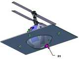
이에 본 발명에서는 도 2a에 도시된 바와 같이 무인항공기에는 무인지상차량과의 결합 착륙을 위한 구형 탑재부(10)를 구비하고 무인지상차량에는 무인항공기의 구형 탑재부가 결합될 수 있는 랜딩부(20)를 구비하도록 하여 도 2b에 도시된 바와 같이 무인지상차량의 표면이 평형을 이루지 않고 경사진 경우라도 오목한 랜딩부에 무인항공기가 용이하게 수용할 수 있고 약간의 위치 오차가 발생하더라도 항상 동일한 위치에 무인항공기를 착륙시킬 수 있도록 하는 것을 특징으로 한다.Accordingly, in the present invention, as shown in Figure 2a, the unmanned aerial vehicle has a spherical mounting
본 발명에 따른 무인항공기의 바람직한 실시예가 도 3에 도시되어 있다.A preferred embodiment of the unmanned aerial vehicle according to the present invention is shown in FIG.
본 발명에 따른 무인항공기에 구비되어 있는 구형 탑재부(10)는 무인항공기 동체 아래에 별도로 구비할 수도 있다. 그러나 도 3에 도시되어 있는 바와 같이 무인항공기 구조의 단순화 및 경량화를 위해 무인항공기의 동체 자체를 구형 탑재부로 구성하는 것이 보다 바람직하고, 구형 동체를 가질 경우 축대칭 형상으로 인해 외란으로 인한 비선형 유체 유동을 줄일 수 있는 추가적인 효과도 있다.Spherical mounting
또한 구형 동체로 구성하는 경우 일반적인 헬리콥터형은 꼬리로터로 인해 구현이 용이하지 않으므로 본 발명은 두 개의 메인로터로 구성된 동축반전형 헬리콥터에 적용되는 것이 보다 바람직하다.In addition, in the case of a spherical fuselage, since a general helicopter type is not easy to implement due to the tail rotor, the present invention is more preferably applied to a coaxial inverted helicopter composed of two main rotors.
본 발명의 구형 탑재부(10)에는 도 3에 도시되어 있는 바와 같이 접이식 강착부(11)를 더 포함할 수 있다. 즉, 본 발명에 따른 무인항공기가 무인지상차량에 착륙할 때에는 일반적인 랜딩기어가 필요 없으나 무인지상차량 이외의 곳에 단독 착륙하기 위해서는 착륙을 위한 랜딩기어가 필요할 수 있다. 따라서 본 발명에 따른 무인항공기에서는 바람직하게 구형 탑재부의 기능을 위해 평소에는 구형 탑재부 외부를 돌출되지 않으며(도 3a 참조), 단독 착륙시에는 구형 탑재부 외부로 펼쳐져(도 3b 참조) 랜딩기어로서 기능하는 접이식 강착부(11)를 구비한다.The
또한 무인항공기 특히 도시된 헬리콥터형 무인항공기의 경우 소모동력이 크기 때문에 구형 탑재부에는 전원 재충전을 위한 커플러(12)를 더 포함할 수 있다. 이 때 상기 커플러는 무인지상차량의 전원공급부에 접속하여 전원이 재충전되도록 구형 탑재부 중 무인지상차량의 랜딩부와 맞닿는 곳에 위치하고, 구형 탑재부 외부로 돌출되지 않는 형태로 구성하는 것이 바람직하며, 본 발명에 따른 무인지상차량 은 상기 서술한 본 발명에 따른 무인항공기의 구형 탑재부(10) 일부가 삽입되어 결합 착륙할 수 있는 랜딩부(20)를 구비하는 것을 특징으로 한다.In addition, in the case of an unmanned aerial vehicle, especially the illustrated helicopter type unmanned aerial vehicle, since the power consumption is large, the old payload may further include a
상기 랜딩부는 도 4에 도시된 바와 같이 상기 구형 탑재부(10)가 거치될 수 있도록 무인지상차량의 내부로 거치공간을 갖도록 형성되며, 표면은 구형 탑재부에 대응하는 원형홀 형태로 구성할 수 있으며, 바람직하게는 도 5에 도시되어 있는 바와 같이 구형 탑재부의 일부분에 대응하는 반구형으로 구성할 수 있다.The landing portion is formed to have a mounting space into the inside of the unmanned vehicle so that the spherical mounting
상기 랜딩부 내부에는 무인항공기 커플러(12)와 결합하여 무인항공기를 재충전시키기 위한 전원을 공급하는 전원공급부(21)가 형성되어 있다. 상기 전원공급부는 무인항공기가 무인지상차량과 평행하게 위치되었을 때 커플러(12)에 대응하는 위치에 형성하는 것이 바람직하다.A
무인항공기(100)는 무인지상차량(200)에 착륙한 후 무인지상차량과 함께 이동하기 때문에 무인항공기를 안정적으로 위치시키기 위한 적절한 구속장치를 무인지상차량에 설치한다. 바람직한 실시예로 도 5에 도시되어 있는 것과 같은 링크암(30, 40, 50, 60)을 설치할 수 있다.Since the unmanned
링크암은 무인지상차량 표면에 설치될 수 있으며, 무인항공기(100)를 안정적으로 고정시키면서도 이착륙시 방해가 되지 않도록 무인항공기 착륙 위치에 가까워지는 방향 및 멀어지는 방향으로 이동 가능하다. 여기서의 이동은 직선 또는 축회전 방식을 모두 포함할 수 있으며, 도 5에는 4개의 링크암이 도시되어 있으나 그 수에 제한되지 않으며 무인항공기를 구속하기 적절한 수로 당업자가 적절히 구성할 수 있다.The link arm may be installed on the surface of the unmanned aerial vehicle and may move in a direction close to and close to the unmanned aerial vehicle landing position while stably fixing the unmanned
주로 험지를 주행하는 무인지상차량은 주행도로의 상태에 따라 기울어져 수평상태(중력방향에 수직인 상태)를 유지하는 경우가 드물고, 이런 상태에서도 본 발명에 따른 무인항공기는 구형 탑재부(10)를 구비함으로써 무인항공기의 랜딩부(20)에 용이하게 착륙할 수 있으며, 구속장치에 의해 안정적으로 고정될 수 있다.An unmanned vehicle mainly traveling in rough terrain rarely maintains a horizontal state (perpendicular to the direction of gravity) inclined according to the state of the road, and even in such a state, the unmanned aerial vehicle according to the present invention may use the
그러나 무인항공기(100)가 무인지상차량(200)에 상대적으로 기울어져 있으면 서로 평형상태를 이룰 때보다 이동시 안정적이지 못하며, 무인항공기의 커플러(12)가 무인지상차량의 전원공급부(21)와 결합하지 못해 동력 충전이 어렵다.However, if the unmanned
따라서 무인지상차량에는 착륙한 무인항공기를 원하는 위치로 이동시키기 위한 이동장치를 더 포함하는 것이 바람직하며, 이러한 이동장치로 무인항공기와 맞닿는 링크암(30, 40, 50, 60)의 말단에 구동휠(31, 41, 51, 61)을 설치할 수 있다.Therefore, it is preferable that the unmanned vehicle further includes a moving device for moving the landed unmanned aerial vehicle to a desired position, and the driving wheel at the end of the
상기 구동휠은 도 6에 도시된 바와 같이 무인항공기의 고도각 및 방위각을 모두 정렬할 수 있는 방향으로 회전되는 것이 바람직하다. 이를 위해 구동휠 중 마주보는 일부 구동휠(41, 61)은 무인항공기의 고도각을 조정할 수 있고, 나머지 구동휠(31, 51)은 무인항공기의 방위각을 조정할 수 있도록 구성하여 링크암이 무인항공기의 고도각 및 방위각을 모두 정렬할 수 있게 할 수 있으며, 링크암의 개수가 적을 때에는 하나의 구동휠이 고도각 및 방위각을 모두 정렬할 수 있도록 그 회전축이 회전될 수 있게 구성할 수도 있다.The driving wheel is preferably rotated in a direction that can align both the altitude and azimuth of the unmanned aerial vehicle as shown in FIG. To this end, some of the driving
위와 같은 구동휠에 의해 무인항공기는 착륙한 경우에는 무인항공기가 무인지상차량과 서로 평형을 이루는 위치 또는 무인항공기 커플러가 전원공급부와 결합 되는 위치로 회전이동되며, 이륙할 경우에는 무인항공기가 수평을 이루는 위치로 움직일 수 있다.When the unmanned aerial vehicle is landed by the above driving wheel, the unmanned aerial vehicle is rotated to a position where the unmanned aerial vehicle is in equilibrium with the unmanned vehicle or the unmanned aerial vehicle coupler is coupled with the power supply unit. Can be moved to the desired position.
이렇게 착륙한 무인항공기의 위치가 자유롭게 이동 가능하므로 무인항공기를 무인지상차량에 정밀하게 착륙시켜야 하는 부담을 경감할 수 있다.Since the position of the unmanned aerial vehicle which has landed in this way can be freely moved, the burden of precisely landing the unmanned aerial vehicle on the unmanned vehicle can be reduced.
상기와 같은 본 발명에 따른 무인항공기가 무인지상차량으로부터 이륙 후 착륙까지의 모습이 도 7에 개략적으로 도시되어 있다.The unmanned aerial vehicle according to the present invention as described above is shown schematically in Figure 7 from the unmanned vehicle to the landing after takeoff.
도 7을 참고로 임무 수행시 무인항공기와 무인지상차량의 일련의 동작을 보다 상세히 설명하면, 무인항공기(100)는 이륙전에는 무인지상차량(200)에 탑재된 상태로 충전되면서 이동되며(도 7a), 감시 정찰을 위해 이륙할 때에는 우선, 무인지상차량은 정지 상태를 유지하고, 충전을 위한 커플러(12)와 전원공급부의 결합이 해지되고, 구동휠이 무인항공기를 수평한 상태로 정렬하고, 링크암이 해제된 후 무인항공기가 이륙한다(도 7b).Referring to FIG. 7 to describe in more detail a series of operations of the unmanned aerial vehicle and the unmanned vehicle, the unmanned
이륙후 무인항공기는 무인지상차량과 교신하면서 감시 정찰 임무를 수행하며(도 7c), 임무를 수행한 무인항공기는 경사진 무인지상차량의 랜딩부에 착륙하고 링크암이 구속상태로 전환된다(도 7d). 그 후 구동휠이 구동되어 무인항공기의 커플러가 무인지상차량의 전원공급부와 결합될 수 있도록 무인항공기의 자세를 재정렬하면 커플러와 전원공급부가 결합되어 재충전이 수행된다(도 7e).After takeoff, the unmanned aerial vehicle performs a surveillance reconnaissance mission while communicating with the unmanned aerial vehicle (FIG. 7C), and the unmanned aerial vehicle performing the mission lands at the landing of the inclined unmanned aerial vehicle, and the link arm is converted into a restraint state (FIG. 7C). 7d). Thereafter, when the driving wheel is driven to rearrange the unmanned aerial vehicle so that the coupler of the unmanned aerial vehicle can be coupled with the power supply unit of the unmanned vehicle, the coupler and the power supply unit are combined to perform recharging (FIG. 7E).
지금까지 본 발명의 특정 실시예를 참조로 본 발명을 설명하였으나 본 발명의 단순한 변형 내지 변경은 이 분야에서 통상의 지식을 가진 자에 의하여 용이하게 실시 될 수 있으며, 이러한 변형이나 변경은 모두 본 발명의 영역에 포함되는 것으로 해석되어야 할 것이다.So far, the present invention has been described with reference to specific embodiments of the present invention, but simple modifications or changes of the present invention can be easily carried out by those skilled in the art, and all such modifications or changes can be made by the present invention. It should be interpreted as being included in the scope of.
도 1은 일반적인 무인항공기가 무인지상차량의 표면에 착륙하는 상황을 개략적으로 도시한 도면으로, 도 1a는 무인지상차량이 수평한 경우, 도 1b는 무인지상차량이 경사진 경우를 나타낸 도면이다.FIG. 1 is a view schematically illustrating a situation where a general unmanned aerial vehicle lands on the surface of an unmanned aerial vehicle, and FIG. 1A is a diagram illustrating a case where the unmanned aerial vehicle is inclined, and FIG.
도 2는 본 발명에 따른 무인항공기가 무인지상차량의 표면에 착륙하는 상황을 개략적으로 도시한 도면으로, 도 2a는 무인지상차량이 수평한 경우, 도 2b는 무인지상차량이 경사진 경우를 나타낸 도면이다.FIG. 2 is a view schematically illustrating a situation in which an unmanned aerial vehicle lands on a surface of an unmanned aerial vehicle according to the present invention, and FIG. 2A illustrates a case where the unmanned aerial vehicle is horizontal, and FIG. 2B illustrates a case where the unmanned aerial vehicle is inclined. Drawing.
도 3은 본 발명에 따른 무인항공기를 보여주는 사시도로서, 도 3a는 접이식 강착부가 접혀진 상태, 도 3b는 펼쳐진 상태를 나타낸 도면이다.Figure 3 is a perspective view showing an unmanned aerial vehicle according to the present invention, Figure 3a is a state showing the folded folding portion, Figure 3b is a view showing the unfolded state.
도 4는 본 발명에 따른 무인지상차량의 랜딩부에 본 발명에 따른 무인항공기가 착륙한 후 재충전을 위해 결합된 상태를 보여주는 일부 절개 사시도이다.4 is a partially cutaway perspective view showing a state in which the unmanned aerial vehicle according to the present invention is coupled for recharging after landing of the unmanned aerial vehicle according to the present invention.
도 5는 본 발명에 따른 무인항공기의 착륙 전후 구속장치인 링크부의 이동 모습을 보여주는 도면이다.5 is a view showing the movement of the link portion that is a restraint device before and after landing of the unmanned aerial vehicle according to the present invention.
도 6은 구동휠이 본 발명에 따른 무인항공기의 고도각 및 방위각을 정렬하는 모습을 보여주는 도면이다.6 is a view showing the driving wheel to align the altitude and azimuth of the unmanned aerial vehicle according to the present invention.
도 7은 본 발명에 따른 무인항공기가 무인지상차량으로부터 이륙 후 착륙까지의 모습을 개략적으로 보여주는 도면이다.7 is a view schematically showing a state from the unmanned aerial vehicle to the landing after takeoff from the unmanned aerial vehicle according to the present invention.
[도면의 주요부호에 대한 간단한 설명][Brief description of the main symbols in the drawings]
10 : 구형 탑재부11 : 접이식 강착부10: spherical mounting portion 11: folding rigid portion
12 : 커플러20 : 랜딩부12: coupler 20: landing part
21 : 전원공급부30, 40, 50, 60 : 링크암21:
31, 41, 51, 61 : 구동휠100 : 무인항공기31, 41, 51, 61: driving wheel 100: unmanned aerial vehicle
200 : 무인지상차량200: unmanned vehicle
Claims (13)
Translated fromKoreanPriority Applications (2)
| Application Number | Priority Date | Filing Date | Title |
|---|---|---|---|
| KR1020090082687AKR101262968B1 (en) | 2009-09-02 | 2009-09-02 | Unmanned Aerial System Including Unmanned Aerial Vehicle Having Spherical Loading Portion And Unmanned Ground Vehicle Therefor |
| US12/874,173US8418959B2 (en) | 2009-09-02 | 2010-09-01 | Unmanned aerial vehicle having spherical loading portion and unmanned ground vehicle therefor |
Applications Claiming Priority (1)
| Application Number | Priority Date | Filing Date | Title |
|---|---|---|---|
| KR1020090082687AKR101262968B1 (en) | 2009-09-02 | 2009-09-02 | Unmanned Aerial System Including Unmanned Aerial Vehicle Having Spherical Loading Portion And Unmanned Ground Vehicle Therefor |
Publications (2)
| Publication Number | Publication Date |
|---|---|
| KR20110024616A KR20110024616A (en) | 2011-03-09 |
| KR101262968B1true KR101262968B1 (en) | 2013-05-09 |
Family
ID=43755781
Family Applications (1)
| Application Number | Title | Priority Date | Filing Date |
|---|---|---|---|
| KR1020090082687AExpired - Fee RelatedKR101262968B1 (en) | 2009-09-02 | 2009-09-02 | Unmanned Aerial System Including Unmanned Aerial Vehicle Having Spherical Loading Portion And Unmanned Ground Vehicle Therefor |
Country Status (2)
| Country | Link |
|---|---|
| US (1) | US8418959B2 (en) |
| KR (1) | KR101262968B1 (en) |
Cited By (9)
| Publication number | Priority date | Publication date | Assignee | Title |
|---|---|---|---|---|
| US9290277B2 (en) | 2013-12-11 | 2016-03-22 | Hanwha Techwin Co., Ltd. | Surveillance system and surveillance method |
| KR20160073473A (en) | 2014-12-16 | 2016-06-27 | (주)이산솔루션 | Flight management system using smart charge about UAV |
| KR20160103218A (en) | 2015-02-23 | 2016-09-01 | (주)이산솔루션 | Flight management system with smart charge using solar power generation |
| KR101654544B1 (en) | 2016-03-31 | 2016-09-06 | 주식회사 케바드론 | A unmanned aircraft having landing and retention capabilities |
| KR101668639B1 (en) | 2015-11-04 | 2016-10-24 | 유콘시스템 주식회사 | Flight System of mother-baby unmanned aerial vehicle using magnetic force |
| KR101668643B1 (en) | 2015-06-23 | 2016-10-24 | 유콘시스템 주식회사 | Spherical unmanned aerial vehicle with apparatus of view angle |
| KR102336741B1 (en) | 2020-06-04 | 2021-12-07 | 최민준 | Unmanned aerial vehicle having apparatus for control take off |
| KR20210151292A (en) | 2020-06-04 | 2021-12-14 | 한국과학기술연구원 | Unmanned aerial vehicle having apparatus for assistance take off and landing |
| US11829162B2 (en) | 2019-08-15 | 2023-11-28 | Teledyne Flir Detection, Inc. | Unmanned aerial vehicle locking landing pad |
Families Citing this family (89)
| Publication number | Priority date | Publication date | Assignee | Title |
|---|---|---|---|---|
| US9329001B2 (en)* | 2011-10-26 | 2016-05-03 | Farrokh Mohamadi | Remote detection, confirmation and detonation of buried improvised explosive devices |
| NO334631B1 (en)* | 2011-11-24 | 2014-04-28 | Marine Aluminium As | Anchoring device in a helicopter deck |
| ES2649615T3 (en)* | 2012-07-05 | 2018-01-15 | Ums Skeldar Sweden Ab | Landing stop system for vertical take-off and vertical landing vehicles (VTOL), landing and take-off platform for VTOL aerial vehicles and VTOL blocking member for aerial vehicles |
| CN103010070B (en)* | 2012-11-30 | 2015-06-03 | 山东电力集团公司电力科学研究院 | Unmanned aerial vehicle comprehensive ground station system and application method thereof |
| US8880241B2 (en)* | 2013-02-20 | 2014-11-04 | Farrokh Mohamadi | Vertical takeoff and landing (VTOL) small unmanned aerial system for monitoring oil and gas pipelines |
| KR101447809B1 (en)* | 2013-03-22 | 2014-10-08 | 김명호 | Aerial Vehicle With Mltipurpose Grip Type Taking Off an Landing Devic |
| US9701425B2 (en) | 2013-08-23 | 2017-07-11 | Korea Aerospace Research Institute | Apparatus and method of charging and housing of unmanned vertical take-off and landing (VTOL) aircraft |
| US9464902B2 (en)* | 2013-09-27 | 2016-10-11 | Regents Of The University Of Minnesota | Symbiotic unmanned aerial vehicle and unmanned surface vehicle system |
| US9557742B2 (en) | 2013-11-27 | 2017-01-31 | Aurora Flight Sciences Corporation | Autonomous cargo delivery system |
| AU2015204838B2 (en) | 2014-01-10 | 2020-01-02 | Pictometry International Corp. | Unmanned aircraft structure evaluation system and method |
| KR101580609B1 (en) | 2014-04-25 | 2015-12-28 | 연세대학교 산학협력단 | Unmanned ground vehicle equipped with unmanned aerial vehicle |
| US9561871B2 (en)* | 2014-05-07 | 2017-02-07 | Deere & Company | UAV docking system and method |
| WO2015180180A1 (en) | 2014-05-30 | 2015-12-03 | SZ DJI Technology Co., Ltd. | Systems and methods for uav docking |
| US9499265B2 (en)* | 2014-07-02 | 2016-11-22 | Skycatch, Inc. | Unmanned aerial vehicle landing interface |
| US9704409B2 (en)* | 2014-08-05 | 2017-07-11 | Qualcomm Incorporated | Piggybacking unmanned aerial vehicle |
| JP6395835B2 (en) | 2014-08-08 | 2018-09-26 | エスゼット ディージェイアイ テクノロジー カンパニー リミテッドSz Dji Technology Co.,Ltd | UAV battery power backup system and method |
| EP3177531B1 (en)* | 2014-08-08 | 2019-05-01 | SZ DJI Technology Co., Ltd. | Multi-zone battery exchange system for uav |
| EP3167535B1 (en) | 2014-08-08 | 2020-09-23 | SZ DJI Technology Co., Ltd. | Systems and methods for uav battery exchange |
| US9545852B2 (en) | 2014-10-02 | 2017-01-17 | Swift Engineering, Inc. | Transportable ground station for an unmanned aerial vehicle |
| CN106103281B (en) | 2014-11-21 | 2019-02-26 | 深圳市大疆创新科技有限公司 | Systems and methods for managing unmanned aerial vehicles |
| US9760087B2 (en)* | 2015-01-16 | 2017-09-12 | International Business Machines Corporation | Distributed, unmanned aerial vehicle package transport network |
| US9776713B2 (en) | 2015-01-21 | 2017-10-03 | Jaime G. Sada-Salinas | Off-board gyrocopter take-off systems and associated methods |
| WO2016130855A1 (en)* | 2015-02-12 | 2016-08-18 | Aerovironment, Inc. | Power and communication interface for vertical take-off and landing (vtol) unmanned aerial vehicles (uavs) |
| US9625904B2 (en)* | 2015-03-24 | 2017-04-18 | Southwest Research Institute | Unmanned ground/aerial vehicle system having autonomous ground vehicle that remotely controls one or more aerial vehicles |
| CN107614375A (en)* | 2015-04-06 | 2018-01-19 | 阿肯技术公司 | The vertical take-off and landing unmanned ground moving system plugin for driving aircraft |
| US10407182B1 (en)* | 2015-04-07 | 2019-09-10 | Board Of Trustees Of The University Of Alabama, For And On Behalf Of The University Of Alabama In Huntsville | Unmanned aerial vehicle docking system |
| US9828093B2 (en) | 2015-05-27 | 2017-11-28 | First Principles, Inc. | System for recharging remotely controlled aerial vehicle, charging station and rechargeable remotely controlled aerial vehicle, and method of use thereof |
| CN107924190A (en) | 2015-06-23 | 2018-04-17 | 阿肯技术公司 | System for autonomous operation of multiple hybrid unmanned aerial vehicles supported by recharging stations to perform services |
| US10933996B2 (en) | 2015-08-03 | 2021-03-02 | Lockheed Martin Corporation | Release and capture of a fixed-wing aircraft |
| JP6908937B2 (en)* | 2015-08-17 | 2021-07-28 | エイチ3 ダイナミックス ホールディングス プライベート リミテッド | Drone box |
| KR101780281B1 (en) | 2015-09-23 | 2017-10-10 | 현대자동차주식회사 | APPARATUS AND METHOD FOR SENDING SOS IN VEHICLE ENAGED WITH uninhabited aerial vehicle |
| AU2016376213A1 (en)* | 2015-12-21 | 2018-07-05 | Airscort Ltd. | Autonomous docking station for drones |
| AU2017206097B2 (en) | 2016-01-08 | 2021-07-08 | Pictometry International Corp. | Systems and methods for taking, processing, retrieving, and displaying images from unmanned aerial vehicles |
| GB2548369B (en)* | 2016-03-15 | 2021-02-17 | Jaguar Land Rover Ltd | System for providing land vehicle support operations using an unmanned autonomous vehicle |
| CN105818966B (en)* | 2016-03-25 | 2017-12-29 | 余江 | The landing fixing device and its fixing means of unmanned vehicle |
| US10370089B2 (en) | 2016-03-30 | 2019-08-06 | Lockheed Martin Corporation | Weight-shifting coaxial helicopter |
| US10502188B2 (en) | 2016-03-30 | 2019-12-10 | Lockheed Martin Corporation | Wind-powered recharging for a weight-shifting coaxial helicopter |
| US10814968B2 (en) | 2016-03-30 | 2020-10-27 | Lockheed Martin Corporation | Hinge mechanism for a weight-shifting coaxial helicopter |
| US10287014B2 (en) | 2016-06-09 | 2019-05-14 | International Business Machines Corporation | Unmanned aerial vehicle coupling apparatus for drone coupling with vehicles |
| KR102658525B1 (en)* | 2016-10-06 | 2024-04-18 | 삼성전자주식회사 | Unmanned aerial vehicle and operating method thereof |
| US9866313B1 (en)* | 2016-12-14 | 2018-01-09 | T-Mobile Usa, Inc. | UAV cellular communication service delivery |
| CN106892119A (en) | 2016-10-21 | 2017-06-27 | 北京京东尚科信息技术有限公司 | Automatic unloading carrier and unmanned plane |
| CN106516089B (en)* | 2016-10-28 | 2019-05-21 | 深圳市道通智能航空技术有限公司 | Unmanned plane |
| US10514690B1 (en) | 2016-11-15 | 2019-12-24 | Amazon Technologies, Inc. | Cooperative autonomous aerial and ground vehicles for item delivery |
| GB2559580B (en)* | 2017-02-09 | 2020-02-12 | Jaguar Land Rover Ltd | Unmanned Aircraft and Landing System Therefor |
| US20180229852A1 (en)* | 2017-02-16 | 2018-08-16 | International Business Machines Corporation | Vehicle and uav refueling and recharging system |
| KR101942099B1 (en)* | 2017-05-30 | 2019-01-24 | 김상수 | fire suppression drone |
| WO2018236903A1 (en) | 2017-06-20 | 2018-12-27 | Planck Aerosystems Inc. | SYSTEMS AND METHODS FOR RECHARGING A PILOT-FREE AIR VEHICLE ON A MOBILE PLATFORM |
| GB2565569B (en)* | 2017-08-16 | 2019-09-25 | Ford Global Tech Llc | Method and system for landing an unmanned aerial vehicle |
| US10599138B2 (en)* | 2017-09-08 | 2020-03-24 | Aurora Flight Sciences Corporation | Autonomous package delivery system |
| US10426393B2 (en) | 2017-09-22 | 2019-10-01 | Aurora Flight Sciences Corporation | Systems and methods for monitoring pilot health |
| WO2019078812A1 (en)* | 2017-10-16 | 2019-04-25 | Ford Global Technologies, Llc | Positioning systems and methods |
| CN108298064B (en)* | 2017-11-09 | 2024-04-26 | 青岛兰道尔空气动力工程有限公司 | Unconventional yaw control system |
| CN111406020B (en)* | 2017-11-29 | 2025-09-09 | 福特全球技术公司 | UAV landing system and method |
| GB2565383B (en)* | 2017-12-14 | 2019-08-07 | Matthew Russell Iain | Unmanned aerial vehicles |
| IT201800005558A1 (en)* | 2018-05-21 | 2019-11-21 | Apparatus and method for the supervision of an industrial plant | |
| US12084179B2 (en) | 2018-05-23 | 2024-09-10 | Aerovironment, Inc. | System and method for drone tethering |
| NO344486B1 (en)* | 2018-06-07 | 2020-01-13 | FLIR Unmanned Aerial Systems AS | System and method for storing and remotely launching unmanned aerial vehicles |
| WO2020053877A1 (en)* | 2018-09-11 | 2020-03-19 | Srinath MALLIKARJUNAN | Apparatus for aerial transportation of payload |
| US12415632B2 (en) | 2018-09-11 | 2025-09-16 | Srinath MALLIKARJUNAN | Apparatus for aerial transportation of payload |
| US11136120B2 (en) | 2018-10-05 | 2021-10-05 | Aurora Flight Sciences Corporation | Ground operations for autonomous object pickup |
| WO2020106984A1 (en) | 2018-11-21 | 2020-05-28 | Eagle View Technologies, Inc. | Navigating unmanned aircraft using pitch |
| US11392130B1 (en) | 2018-12-12 | 2022-07-19 | Amazon Technologies, Inc. | Selecting delivery modes and delivery areas using autonomous ground vehicles |
| CN109683205B (en)* | 2018-12-28 | 2020-09-11 | 东南大学 | A kind of aerial detection device and ground ejection system |
| US12228407B2 (en) | 2019-01-15 | 2025-02-18 | Aerovironment, Inc. | Systems and methods for delivery using unmanned aerial vehicles |
| DE102019106197A1 (en)* | 2019-03-12 | 2020-09-17 | Volocopter Gmbh | Flight system with a VTOL aircraft and method for vertical take-off and landing of a VTOL aircraft |
| EP3930316A4 (en)* | 2019-03-27 | 2022-04-20 | Sony Group Corporation | INFORMATION PROCESSING DEVICE, METHOD AND PROGRAM |
| US11856882B2 (en)* | 2019-04-10 | 2024-01-02 | Kansas Stte University Research Foundation | Autonomous robot system for steep terrain farming operations |
| US11691761B2 (en)* | 2019-05-17 | 2023-07-04 | FlyFocus Sp. z.o.o. | Detachable power cable for unmanned aerial vehicle |
| CN110104200B (en)* | 2019-05-29 | 2020-11-13 | 北京北方车辆集团有限公司 | Rotor type vehicle-mounted unmanned aerial vehicle locking device |
| US10796562B1 (en) | 2019-09-26 | 2020-10-06 | Amazon Technologies, Inc. | Autonomous home security devices |
| US11260970B2 (en) | 2019-09-26 | 2022-03-01 | Amazon Technologies, Inc. | Autonomous home security devices |
| CN110667870B (en)* | 2019-10-12 | 2023-01-20 | 内蒙古工业大学 | Unmanned aerial vehicle is energy autonomous base station of independently taking off and land trading battery based on solar energy power supply |
| DE102019132056A1 (en)* | 2019-11-26 | 2021-05-27 | Heggemann Ag | Carrier trolley for STOL / VTOL aircraft |
| US11767110B2 (en) | 2019-12-16 | 2023-09-26 | FLIR Unmanned Aerial Systems AS | System for storing, autonomously launching and landing unmanned aerial vehicles |
| KR102289040B1 (en)* | 2020-01-31 | 2021-08-11 | 한국로봇융합연구원 | Monitoring robot system in the culvert or atypical space |
| KR102408381B1 (en)* | 2020-02-24 | 2022-06-13 | 주식회사 에어온 | Drone havnig landing gear |
| US11440679B2 (en)* | 2020-10-27 | 2022-09-13 | Cowden Technologies, Inc. | Drone docking station and docking module |
| KR102354364B1 (en)* | 2021-04-29 | 2022-01-21 | 성시언 | Flight vehicle control training device that can be detachable from the robot arm |
| US12280889B1 (en) | 2022-06-30 | 2025-04-22 | Amazon Technologies, Inc. | Indoor navigation and obstacle avoidance for unmanned aerial vehicles |
| US12145753B2 (en)* | 2022-08-09 | 2024-11-19 | Pete Bitar | Compact and lightweight drone delivery device called an ArcSpear electric jet drone system having an electric ducted air propulsion system and being relatively difficult to track in flight |
| US12346128B1 (en) | 2022-09-30 | 2025-07-01 | Amazon Technologies, Inc. | Indoor altitude determination for aerial vehicles |
| KR102814864B1 (en)* | 2022-12-08 | 2025-05-30 | 한국항공우주연구원 | Take-off and landing performance improvement system |
| US12202634B1 (en) | 2023-03-30 | 2025-01-21 | Amazon Technologies, Inc. | Indoor aerial vehicles with advanced safety features |
| CN116176899B (en)* | 2023-04-27 | 2023-07-14 | 北京理工大学 | Ship-borne small-sized vertical take-off and landing fixed wing unmanned aerial vehicle recovery device |
| US12205483B1 (en)* | 2023-06-26 | 2025-01-21 | Amazon Technologies, Inc. | Selecting paths for indoor obstacle avoidance by unmanned aerial vehicles |
| US12227318B1 (en) | 2023-09-28 | 2025-02-18 | Amazon Technologies, Inc. | Aerial vehicles with proximity sensors for safety |
| KR102653949B1 (en)* | 2023-10-13 | 2024-04-03 | 주식회사 볼로랜드 | System for adjusting the center and balloon drone station |
| US12344411B1 (en)* | 2024-04-03 | 2025-07-01 | Hoodman Corporation | Foldable launch and landing pad for drones |
Citations (3)
| Publication number | Priority date | Publication date | Assignee | Title |
|---|---|---|---|---|
| US20030125119A1 (en) | 2001-12-29 | 2003-07-03 | Steven Jones | Nimble virtual reality capsule using rotatable drive assembly |
| JP2003341599A (en) | 2002-05-27 | 2003-12-03 | Sharp Corp | Information presentation device and information presentation system |
| US20040167682A1 (en) | 2003-02-21 | 2004-08-26 | Lockheed Martin Corporation | Virtual sensor mast |
Family Cites Families (9)
| Publication number | Priority date | Publication date | Assignee | Title |
|---|---|---|---|---|
| US3135057A (en)* | 1960-04-28 | 1964-06-02 | Northrop Corp | Flight simulator |
| US3149803A (en)* | 1961-07-19 | 1964-09-22 | Us Industries Inc | Tethered hovering platform |
| US3395876A (en)* | 1966-05-05 | 1968-08-06 | Jacob B. Green | Aircraft with housed counter rotating propellors |
| US3507461A (en)* | 1967-06-16 | 1970-04-21 | Vlm Corp The | Rotary wing aircraft |
| US3795372A (en)* | 1971-08-23 | 1974-03-05 | L Feldman | Sail rotor crane |
| US4184654A (en)* | 1978-06-26 | 1980-01-22 | Herrera Samuel M | Rotor aircraft |
| US5490784A (en)* | 1993-10-29 | 1996-02-13 | Carmein; David E. E. | Virtual reality system with enhanced sensory apparatus |
| US5667167A (en)* | 1994-09-02 | 1997-09-16 | Kistler Aerospace Corporation | Methods and apparatus for reusable launch platform and reusable spacecraft |
| CA2269149C (en)* | 1999-04-16 | 2003-07-08 | John Scott Davidson | Operating and mooring facility for tethered gas balloon |
- 2009
- 2009-09-02KRKR1020090082687Apatent/KR101262968B1/ennot_activeExpired - Fee Related
- 2010
- 2010-09-01USUS12/874,173patent/US8418959B2/ennot_activeExpired - Fee Related
Patent Citations (3)
| Publication number | Priority date | Publication date | Assignee | Title |
|---|---|---|---|---|
| US20030125119A1 (en) | 2001-12-29 | 2003-07-03 | Steven Jones | Nimble virtual reality capsule using rotatable drive assembly |
| JP2003341599A (en) | 2002-05-27 | 2003-12-03 | Sharp Corp | Information presentation device and information presentation system |
| US20040167682A1 (en) | 2003-02-21 | 2004-08-26 | Lockheed Martin Corporation | Virtual sensor mast |
Cited By (9)
| Publication number | Priority date | Publication date | Assignee | Title |
|---|---|---|---|---|
| US9290277B2 (en) | 2013-12-11 | 2016-03-22 | Hanwha Techwin Co., Ltd. | Surveillance system and surveillance method |
| KR20160073473A (en) | 2014-12-16 | 2016-06-27 | (주)이산솔루션 | Flight management system using smart charge about UAV |
| KR20160103218A (en) | 2015-02-23 | 2016-09-01 | (주)이산솔루션 | Flight management system with smart charge using solar power generation |
| KR101668643B1 (en) | 2015-06-23 | 2016-10-24 | 유콘시스템 주식회사 | Spherical unmanned aerial vehicle with apparatus of view angle |
| KR101668639B1 (en) | 2015-11-04 | 2016-10-24 | 유콘시스템 주식회사 | Flight System of mother-baby unmanned aerial vehicle using magnetic force |
| KR101654544B1 (en) | 2016-03-31 | 2016-09-06 | 주식회사 케바드론 | A unmanned aircraft having landing and retention capabilities |
| US11829162B2 (en) | 2019-08-15 | 2023-11-28 | Teledyne Flir Detection, Inc. | Unmanned aerial vehicle locking landing pad |
| KR102336741B1 (en) | 2020-06-04 | 2021-12-07 | 최민준 | Unmanned aerial vehicle having apparatus for control take off |
| KR20210151292A (en) | 2020-06-04 | 2021-12-14 | 한국과학기술연구원 | Unmanned aerial vehicle having apparatus for assistance take off and landing |
Also Published As
| Publication number | Publication date |
|---|---|
| US8418959B2 (en) | 2013-04-16 |
| KR20110024616A (en) | 2011-03-09 |
| US20110068224A1 (en) | 2011-03-24 |
Similar Documents
| Publication | Publication Date | Title |
|---|---|---|
| KR101262968B1 (en) | Unmanned Aerial System Including Unmanned Aerial Vehicle Having Spherical Loading Portion And Unmanned Ground Vehicle Therefor | |
| AU2020220083B2 (en) | Landing and payload loading structures | |
| EP3784568B1 (en) | Vertical takeoff and landing aircraft | |
| US10850835B2 (en) | Unmanned aerial vehicle with monolithic wing and twin-rotor propulsion/lift modules | |
| EP3638585B1 (en) | System and method for launching an unmanned aerial vehicle | |
| EP3140188B1 (en) | Vertical takeoff and landing (vtol) unmanned aerial vehicle (uav) | |
| US11292594B2 (en) | System of play platform for multi-mission application spanning any one or combination of domains or environments | |
| US9682774B2 (en) | System, apparatus and method for long endurance vertical takeoff and landing vehicle | |
| US10967960B2 (en) | Ground movement system plugin for VTOL UAVs | |
| US11319065B2 (en) | Suspended aerial vehicle system with thruster stabilization | |
| US9580172B2 (en) | Multiple environment unmanned vehicle | |
| CN111512253A (en) | Active position control of rope hook | |
| US20180222583A1 (en) | UAV Booster Aircraft for Takeoff and Climb Assist | |
| CA3121486A1 (en) | Ducted fan unmanned aerial vehicle docking station | |
| US11767130B2 (en) | System and method for launching and retrieving unmanned aerial vehicle from carrier in motion | |
| US11994876B2 (en) | In-flight UAV deployment and retrieval platform | |
| US10246185B2 (en) | Aircraft system and method for vertical takeoff and landing | |
| CN110104199B (en) | A kind of take-off and landing device for UAV aerial launch platform | |
| Byun et al. | Conceptual study of a smart docking system for VTOL-UAV | |
| CN115379987B (en) | Modularized unmanned aerial vehicle system suitable for parcel delivery |
Legal Events
| Date | Code | Title | Description |
|---|---|---|---|
| A201 | Request for examination | ||
| PA0109 | Patent application | St.27 status event code:A-0-1-A10-A12-nap-PA0109 | |
| PA0201 | Request for examination | St.27 status event code:A-1-2-D10-D11-exm-PA0201 | |
| PG1501 | Laying open of application | St.27 status event code:A-1-1-Q10-Q12-nap-PG1501 | |
| D13-X000 | Search requested | St.27 status event code:A-1-2-D10-D13-srh-X000 | |
| D14-X000 | Search report completed | St.27 status event code:A-1-2-D10-D14-srh-X000 | |
| E902 | Notification of reason for refusal | ||
| PE0902 | Notice of grounds for rejection | St.27 status event code:A-1-2-D10-D21-exm-PE0902 | |
| AMND | Amendment | ||
| P11-X000 | Amendment of application requested | St.27 status event code:A-2-2-P10-P11-nap-X000 | |
| P13-X000 | Application amended | St.27 status event code:A-2-2-P10-P13-nap-X000 | |
| R17-X000 | Change to representative recorded | St.27 status event code:A-3-3-R10-R17-oth-X000 | |
| E902 | Notification of reason for refusal | ||
| PE0902 | Notice of grounds for rejection | St.27 status event code:A-1-2-D10-D21-exm-PE0902 | |
| E601 | Decision to refuse application | ||
| PE0601 | Decision on rejection of patent | St.27 status event code:N-2-6-B10-B15-exm-PE0601 | |
| X091 | Application refused [patent] | ||
| AMND | Amendment | ||
| E13-X000 | Pre-grant limitation requested | St.27 status event code:A-2-3-E10-E13-lim-X000 | |
| P11-X000 | Amendment of application requested | St.27 status event code:A-2-2-P10-P11-nap-X000 | |
| P13-X000 | Application amended | St.27 status event code:A-2-2-P10-P13-nap-X000 | |
| PX0901 | Re-examination | St.27 status event code:A-2-3-E10-E12-rex-PX0901 | |
| PX0601 | Decision of rejection after re-examination | St.27 status event code:N-2-6-B10-B17-rex-PX0601 | |
| J201 | Request for trial against refusal decision | ||
| PJ0201 | Trial against decision of rejection | St.27 status event code:A-3-3-V10-V11-apl-PJ0201 | |
| J301 | Trial decision | Free format text:TRIAL DECISION FOR APPEAL AGAINST DECISION TO DECLINE REFUSAL REQUESTED 20121012 Effective date:20130321 | |
| PJ1301 | Trial decision | St.27 status event code:A-3-3-V10-V15-crt-PJ1301 Decision date:20130321 Appeal event data comment text:Appeal Kind Category : Appeal against decision to decline refusal, Appeal Ground Text : 2009 0082687 Appeal request date:20121012 Appellate body name:Patent Examination Board Decision authority category:Office appeal board Decision identifier:2012101008730 | |
| PS0901 | Examination by remand of revocation | St.27 status event code:A-6-3-E10-E12-rex-PS0901 | |
| S901 | Examination by remand of revocation | ||
| GRNO | Decision to grant (after opposition) | ||
| PS0701 | Decision of registration after remand of revocation | St.27 status event code:A-3-4-F10-F13-rex-PS0701 | |
| GRNT | Written decision to grant | ||
| PR0701 | Registration of establishment | St.27 status event code:A-2-4-F10-F11-exm-PR0701 | |
| PR1002 | Payment of registration fee | St.27 status event code:A-2-2-U10-U11-oth-PR1002 Fee payment year number:1 | |
| PG1601 | Publication of registration | St.27 status event code:A-4-4-Q10-Q13-nap-PG1601 | |
| PN2301 | Change of applicant | St.27 status event code:A-5-5-R10-R13-asn-PN2301 St.27 status event code:A-5-5-R10-R11-asn-PN2301 | |
| R18-X000 | Changes to party contact information recorded | St.27 status event code:A-5-5-R10-R18-oth-X000 | |
| FPAY | Annual fee payment | Payment date:20160509 Year of fee payment:4 | |
| PR1001 | Payment of annual fee | St.27 status event code:A-4-4-U10-U11-oth-PR1001 Fee payment year number:4 | |
| PN2301 | Change of applicant | St.27 status event code:A-5-5-R10-R11-asn-PN2301 | |
| PN2301 | Change of applicant | St.27 status event code:A-5-5-R10-R14-asn-PN2301 | |
| P14-X000 | Amendment of ip right document requested | St.27 status event code:A-5-5-P10-P14-nap-X000 | |
| P16-X000 | Ip right document amended | St.27 status event code:A-5-5-P10-P16-nap-X000 | |
| Q16-X000 | A copy of ip right certificate issued | St.27 status event code:A-4-4-Q10-Q16-nap-X000 | |
| PN2301 | Change of applicant | St.27 status event code:A-5-5-R10-R11-asn-PN2301 | |
| PN2301 | Change of applicant | St.27 status event code:A-5-5-R10-R14-asn-PN2301 | |
| P14-X000 | Amendment of ip right document requested | St.27 status event code:A-5-5-P10-P14-nap-X000 | |
| R18-X000 | Changes to party contact information recorded | St.27 status event code:A-5-5-R10-R18-oth-X000 | |
| R18-X000 | Changes to party contact information recorded | St.27 status event code:A-5-5-R10-R18-oth-X000 | |
| P16-X000 | Ip right document amended | St.27 status event code:A-5-5-P10-P16-nap-X000 | |
| Q16-X000 | A copy of ip right certificate issued | St.27 status event code:A-4-4-Q10-Q16-nap-X000 | |
| FPAY | Annual fee payment | Payment date:20170522 Year of fee payment:5 | |
| PR1001 | Payment of annual fee | St.27 status event code:A-4-4-U10-U11-oth-PR1001 Fee payment year number:5 | |
| PR1001 | Payment of annual fee | St.27 status event code:A-4-4-U10-U11-oth-PR1001 Fee payment year number:6 | |
| PR1001 | Payment of annual fee | St.27 status event code:A-4-4-U10-U11-oth-PR1001 Fee payment year number:7 | |
| FPAY | Annual fee payment | Payment date:20200312 Year of fee payment:8 | |
| PR1001 | Payment of annual fee | St.27 status event code:A-4-4-U10-U11-oth-PR1001 Fee payment year number:8 | |
| PR1001 | Payment of annual fee | St.27 status event code:A-4-4-U10-U11-oth-PR1001 Fee payment year number:9 | |
| PR1001 | Payment of annual fee | St.27 status event code:A-4-4-U10-U11-oth-PR1001 Fee payment year number:10 | |
| PR1001 | Payment of annual fee | St.27 status event code:A-4-4-U10-U11-oth-PR1001 Fee payment year number:11 | |
| PN2301 | Change of applicant | St.27 status event code:A-5-5-R10-R13-asn-PN2301 St.27 status event code:A-5-5-R10-R11-asn-PN2301 | |
| P22-X000 | Classification modified | St.27 status event code:A-4-4-P10-P22-nap-X000 | |
| PC1903 | Unpaid annual fee | St.27 status event code:A-4-4-U10-U13-oth-PC1903 Not in force date:20240504 Payment event data comment text:Termination Category : DEFAULT_OF_REGISTRATION_FEE | |
| R18-X000 | Changes to party contact information recorded | St.27 status event code:A-5-5-R10-R18-oth-X000 | |
| P22-X000 | Classification modified | St.27 status event code:A-4-4-P10-P22-nap-X000 | |
| PN2301 | Change of applicant | St.27 status event code:A-5-5-R10-R13-asn-PN2301 St.27 status event code:A-5-5-R10-R11-asn-PN2301 | |
| R18-X000 | Changes to party contact information recorded | St.27 status event code:A-5-5-R10-R18-oth-X000 | |
| PC1903 | Unpaid annual fee | St.27 status event code:N-4-6-H10-H13-oth-PC1903 Ip right cessation event data comment text:Termination Category : DEFAULT_OF_REGISTRATION_FEE Not in force date:20240504 |