KR101262556B1 - Wireless power transmission apparatus - Google Patents
Wireless power transmission apparatusDownload PDFInfo
- Publication number
- KR101262556B1 KR101262556B1KR1020110105516AKR20110105516AKR101262556B1KR 101262556 B1KR101262556 B1KR 101262556B1KR 1020110105516 AKR1020110105516 AKR 1020110105516AKR 20110105516 AKR20110105516 AKR 20110105516AKR 101262556 B1KR101262556 B1KR 101262556B1
- Authority
- KR
- South Korea
- Prior art keywords
- cell
- cell group
- cells
- wireless power
- coil
- Prior art date
- Legal status (The legal status is an assumption and is not a legal conclusion. Google has not performed a legal analysis and makes no representation as to the accuracy of the status listed.)
- Expired - Fee Related
Links
Images


Classifications
- H—ELECTRICITY
- H02—GENERATION; CONVERSION OR DISTRIBUTION OF ELECTRIC POWER
- H02J—CIRCUIT ARRANGEMENTS OR SYSTEMS FOR SUPPLYING OR DISTRIBUTING ELECTRIC POWER; SYSTEMS FOR STORING ELECTRIC ENERGY
- H02J50/00—Circuit arrangements or systems for wireless supply or distribution of electric power
- H02J50/40—Circuit arrangements or systems for wireless supply or distribution of electric power using two or more transmitting or receiving devices
- H—ELECTRICITY
- H02—GENERATION; CONVERSION OR DISTRIBUTION OF ELECTRIC POWER
- H02J—CIRCUIT ARRANGEMENTS OR SYSTEMS FOR SUPPLYING OR DISTRIBUTING ELECTRIC POWER; SYSTEMS FOR STORING ELECTRIC ENERGY
- H02J50/00—Circuit arrangements or systems for wireless supply or distribution of electric power
- H02J50/10—Circuit arrangements or systems for wireless supply or distribution of electric power using inductive coupling
- H02J50/12—Circuit arrangements or systems for wireless supply or distribution of electric power using inductive coupling of the resonant type
- H—ELECTRICITY
- H02—GENERATION; CONVERSION OR DISTRIBUTION OF ELECTRIC POWER
- H02J—CIRCUIT ARRANGEMENTS OR SYSTEMS FOR SUPPLYING OR DISTRIBUTING ELECTRIC POWER; SYSTEMS FOR STORING ELECTRIC ENERGY
- H02J50/00—Circuit arrangements or systems for wireless supply or distribution of electric power
- H02J50/005—Mechanical details of housing or structure aiming to accommodate the power transfer means, e.g. mechanical integration of coils, antennas or transducers into emitting or receiving devices
- H—ELECTRICITY
- H02—GENERATION; CONVERSION OR DISTRIBUTION OF ELECTRIC POWER
- H02J—CIRCUIT ARRANGEMENTS OR SYSTEMS FOR SUPPLYING OR DISTRIBUTING ELECTRIC POWER; SYSTEMS FOR STORING ELECTRIC ENERGY
- H02J50/00—Circuit arrangements or systems for wireless supply or distribution of electric power
- H02J50/40—Circuit arrangements or systems for wireless supply or distribution of electric power using two or more transmitting or receiving devices
- H02J50/402—Circuit arrangements or systems for wireless supply or distribution of electric power using two or more transmitting or receiving devices the two or more transmitting or the two or more receiving devices being integrated in the same unit, e.g. power mats with several coils or antennas with several sub-antennas
- H—ELECTRICITY
- H04—ELECTRIC COMMUNICATION TECHNIQUE
- H04B—TRANSMISSION
- H04B5/00—Near-field transmission systems, e.g. inductive or capacitive transmission systems
- H04B5/20—Near-field transmission systems, e.g. inductive or capacitive transmission systems characterised by the transmission technique; characterised by the transmission medium
- H04B5/24—Inductive coupling
- H04B5/26—Inductive coupling using coils
- H04B5/266—One coil at each side, e.g. with primary and secondary coils
- H—ELECTRICITY
- H04—ELECTRIC COMMUNICATION TECHNIQUE
- H04B—TRANSMISSION
- H04B5/00—Near-field transmission systems, e.g. inductive or capacitive transmission systems
- H04B5/70—Near-field transmission systems, e.g. inductive or capacitive transmission systems specially adapted for specific purposes
- H04B5/79—Near-field transmission systems, e.g. inductive or capacitive transmission systems specially adapted for specific purposes for data transfer in combination with power transfer
- H—ELECTRICITY
- H01—ELECTRIC ELEMENTS
- H01F—MAGNETS; INDUCTANCES; TRANSFORMERS; SELECTION OF MATERIALS FOR THEIR MAGNETIC PROPERTIES
- H01F38/00—Adaptations of transformers or inductances for specific applications or functions
- H01F38/14—Inductive couplings
- H—ELECTRICITY
- H02—GENERATION; CONVERSION OR DISTRIBUTION OF ELECTRIC POWER
- H02J—CIRCUIT ARRANGEMENTS OR SYSTEMS FOR SUPPLYING OR DISTRIBUTING ELECTRIC POWER; SYSTEMS FOR STORING ELECTRIC ENERGY
- H02J7/00—Circuit arrangements for charging or depolarising batteries or for supplying loads from batteries
Landscapes
- Engineering & Computer Science (AREA)
- Computer Networks & Wireless Communication (AREA)
- Power Engineering (AREA)
- Signal Processing (AREA)
- Charge And Discharge Circuits For Batteries Or The Like (AREA)
- Near-Field Transmission Systems (AREA)
Abstract
Translated fromKorean
Description
Translated fromKorean본 발명은 무선전력 송신장치에 관한 것이다.The present invention relates to a wireless power transmission apparatus.
무선으로 전기 에너지를 원하는 기기로 전달하는 무선전력전송 기술(wireless power transmission 또는 wireless energy transfer)은 이미 1800년대에 전자기유도 원리를 이용한 전기 모터나 변압기가 사용되기 시작했고, 그 후로는 라디오파나 레이저와 같은 전자파를 방사해서 전기에너지를 전송하는 방법도 시도되었다. 우리가 흔히 사용하는 전동칫솔이나 일부 무선면도기도 실상은 전자기유도 원리로 충전된다. 현재까지 무선 방식에 의한 에너지 전달 방식은 자기 유도, 자기 공진 및 단파장 무선 주파수를 이용한 원거리 송신 기술 등이 있다.In the 1800s, electric motors and transformers using electromagnetic induction principles began to be used, and then radio waves and lasers were used to transmit the electric energy to the desired devices wirelessly. A method of transmitting electrical energy by radiating the same electromagnetic wave has also been attempted. Our electric toothbrushes and some wireless shavers are actually charged with electromagnetic induction. To date, energy transmission methods using wireless methods include magnetic induction, magnetic resonance, and long-distance transmission technology using short wavelength radio frequencies.
최근에는 이와 같은 무선 전력 전송 기술 중 자기 공진을 이용한 에너지 전달 방식이 많이 사용되고 있다.Recently, among the wireless power transmission technologies, energy transmission schemes using magnetic resonance have been widely used.
자기 공진을 이용한 무선전력 전송 시스템은 무선전력 송신장치와 무선전력 수신장치 사이에 형성된 전기신호가 코일을 통해 무선으로 전달되기 때문에 사용자는 휴대용 기기와 같은 전자기기를 손쉽게 충전할 수 있다.In a wireless power transmission system using magnetic resonance, an electric signal formed between a wireless power transmitter and a wireless power receiver is wirelessly transmitted through a coil, so that a user can easily charge an electronic device such as a portable device.
그러나, 자기 공진을 이용한 에너지 전달 방식은 송신 측에서 발생하는 자기장이 외부로 누출되는 현상이 발생될 수 있다. 누출된 자기장은 인체에 노출되어 건강에 유해한 영향을 미칠 수 있다.
이와 관련된 선행특허문헌으로는 대한민국 공개특허공보 제10-2010-0024518호가 있다.However, in the energy transmission method using magnetic resonance, a phenomenon in which a magnetic field generated from a transmitting side leaks to the outside may occur. The leaked magnetic field can be exposed to the human body and cause harmful health effects.
Related prior art documents include Korean Laid-Open Patent Publication No. 10-2010-0024518.
본 발명은 목적은 자기 공진에 의한 전력 전송이 이루어지는 과정에서 무선전력 송신장치와 무선전력 수신장치 간에 발생하는 자기장이 외부로 누출되는 것을 최소화하고, 전력 전송의 효율성을 극대화할 수 있는 무선전력 송신장치를 제공함에 있다.An object of the present invention is to minimize the leakage of the magnetic field generated between the wireless power transmitter and the wireless power receiver to the outside in the process of power transmission by magnetic resonance, and to maximize the efficiency of power transmission wireless power transmitter In providing.
본 발명의 실시예에 따른 무선전력 송신장치는 수신장치와 자기 공진 하도록 구성된 코일 및 캐패시터를 포함하고, 상기 코일은 복수의 셀 그룹 및 상기 복수의 셀 그룹을 연결하는 코어를 포함하고, 상기 복수의 셀 그룹 각각은 복수의 셀을 포함하고, 각 셀 그룹의 복수의 셀은 상기 복수의 셀에 흐르는 전류에 의해 발생하는 자기장이 동일한 방향으로 형성되도록 구성되고,In accordance with another aspect of the present invention, a wireless power transmitter includes a coil and a capacitor configured to self-resonate with a receiver, wherein the coil includes a plurality of cell groups and a core connecting the plurality of cell groups. Each cell group includes a plurality of cells, and the plurality of cells of each cell group are configured such that a magnetic field generated by a current flowing in the plurality of cells is formed in the same direction,
각 셀 그룹은 하나 이상의 인접한 셀 그룹을 가지고, 상기 각 셀 그룹 및 상기 코어는 하나의 도선으로 이루어진다..Each cell group has one or more adjacent cell groups, wherein each cell group and the core consist of one conductor.
본 발명의 실시예에 따르면, 다음과 같은 효과가 있다.According to the embodiment of the present invention, the following effects can be obtained.
첫째, 무선전력 송신장치의 코일 구조를 개선하여 자기장이 외부로 누출되는 것을 최소화할 수 있다.First, it is possible to minimize the leakage of the magnetic field to the outside by improving the coil structure of the wireless power transmitter.
둘째, 무선전력 송신장치와 무선전력 수신장치 간 전력 전송 효율을 극대화할 수 있다.Second, the power transmission efficiency between the wireless power transmitter and the wireless power receiver can be maximized.
도 1은 본 발명의 일 실시예에 따른 무선 전력 전송 시스템을 나타낸다.
도 2는 본 발명의 일 실시예에 따른, 송신 코일의 등가 회로도이다.
도 3은 본 발명의 일 실시예에 따른, 전력 소스와 송신부의 등가회로이다.
도 4는 본 발명의 일 실시예에 따른, 수신용 공진 코일, 수신 코일, 평활 회로 및 부하의 등가회로를 나타낸다.
도 5는 본 발명의 일 실시예에 따른 무선전력 송신장치의 구성 예이다.
도 6은 본 발명의 일 실시예에 따른 무선전력 송신장치의 구성 예의 평면도이다.1 shows a wireless power transmission system according to an embodiment of the present invention.
2 is an equivalent circuit diagram of a transmitting coil, in accordance with an embodiment of the present invention.
3 is an equivalent circuit of a power source and a transmitter according to an embodiment of the present invention.
4 shows an equivalent circuit of a receiving resonance coil, a receiving coil, a smoothing circuit and a load according to an embodiment of the present invention.
5 is a configuration example of a wireless power transmission apparatus according to an embodiment of the present invention.
6 is a plan view of a configuration example of a wireless power transmitter according to an embodiment of the present invention.
이하에서는, 첨부된 도면을 참조하여 본 발명의 바람직한 실시예에 대하여 본 발명이 속하는 기술분야에서 통상의 지식을 가진 자가 용이하게 실시할 수 있도록 상세히 설명한다.Hereinafter, preferred embodiments of the present invention will be described in detail with reference to the accompanying drawings, which will be easily understood by those skilled in the art.
도 1은 본 발명의 일 실시예에 따른 무선 전력 전송 시스템을 나타낸다.1 shows a wireless power transmission system according to an embodiment of the present invention.
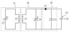
전력 소스(10)에서 생성된 전력은 송신부(20)로 전달되고, 자기 공진 현상에 의해 송신부(20)와 공진을 이루는 즉, 공진 주파수 값이 동일한 수신부(30)로 전달된다. 수신부(30)로 전달된 전력은 정류회로(40)를 거쳐 부하(50)로 전달된다. 부하(50)는 충전지 또는 기타 전력을 필요로 하는 임의의 장치일 수 있다.The power generated by the
보다 구체적으로 살펴보면, 전력 소스(10)는 소정 주파수의 교류 전력을 제공하는 교류 전력 소스이다.More specifically, the
송신부(20)는 송신 코일(21)과 송신용 공진 코일(22)로 구성된다. 송신 코일(21)은 전력 소스(10)와 연결되며, 교류 전류가 흐른다. 송신 코일(21)에 교류 전류가 흐르면, 전자기 유도에 의해 물리적으로 이격되어 있는 송신용 공진 코일(22)에도 교류 전류가 유도된다. 송신용 공진 코일(22)로 전달된 전력은 자기 공진에 의해 송신부(20)와 공진 회로를 이루는 수신부(30)로 전달된다.The
임피던스가 매칭된 2개의 LC 회로 사이는 자기 공진에 의해 전력이 전송될 수 있다. 이와 같은 자기 공진에 의한 전력 전송은 전자기 유도에 의한 전력 전송보다 더 먼 거리까지 더 높은 효율로 전력 전달이 가능하게 한다.Power may be transferred by magnetic resonance between two impedance matched LC circuits. Such power transmission by magnetic resonance enables power transmission with higher efficiency over longer distances than power transmission by electromagnetic induction.
수신부(30)는 수신용 공진 코일(31)과 수신 코일(32)로 구성된다. 송신용 공진 코일(22)에 의해 송신된 전력은 수신용 공진 코일(31)에 의해 수신되어 수신용 공진 코일(31)에 교류 전류가 흐르게 된다. 수신용 공진 코일(31)로 전달된 전력은 전자기 유도에 의해 수신 코일(32)로 전달된다. 수신코일(32)로 전달된 전력은 정류 회로(40)를 통해 정류되어 부하(50)로 전달된다.
The
도 2는 본 발명의 일 실시예에 따른, 송신 코일(21)의 등가 회로도이다. 도 2에 도시된 바와 같이 송신 코일(21)은 인덕터(L1)와 캐패시터(C1)로 구성될 수 있으며, 이들에 의해 적절한 인덕턴스와 캐패시턴스 값을 갖는 회로를 구성하게 된다. 캐패시터(C1)는 가변 캐패시터일 수 있으며, 가변 캐패시터를 조절하여 임피던스 매칭을 수행할 수 있다. 송신용 공진 코일(22), 수신용 공진 코일(31), 수신 코일(32)의 등가 회로도 도 2에 도시된 것과 동일할 수 있다.
2 is an equivalent circuit diagram of the
도 3은 본 발명의 일 실시예에 따른, 전력 소스(10)와 송신부(20)의 등가회로이다. 도 3에 도시된 바와 같이, 송신 코일(21)과 송신용 공진 코일(22)은 각각 소정 인덕턴스 값과 캐패시턴스 값을 갖는 인덕터(L1, L2)와 캐패시터(C1,C2)로 구성될 수 있다.
Figure 3 is an equivalent circuit of a
도 4는 본 발명의 일 실시예에 따른, 수신용 공진 코일(31), 수신 코일(32), 평활 회로(40) 및 부하(50)의 등가회로를 나타낸다.4 shows an equivalent circuit of the receiving
도 4에 도시된 바와 같이 수신용 공진 코일(31)과 수신 코일(32)은 각각 소정 인덕턴스 값과 캐패시턴스 값을 갖는 인덕터(L3,L4)와 캐패시터(C3,C4)로 구성될 수 있다. 평활 회로(40)는 다이오드(D1)와 평활 캐패시터(C5)로 구성될 수 있으며, 교류 전력을 직류 전력을 변환하여 출력한다. 부하(50)는 1.3V의 직류 전원으로 표시되어 있으나, 직류 전력을 필요로 하는 임의의 충전지 또는 장치일 수 있다.
As shown in FIG. 4, the receiving
도 5는 본 발명의 일 실시예에 따른 무선전력 송신장치의 구성 예이다.5 is a configuration example of a wireless power transmission apparatus according to an embodiment of the present invention.
무선전력 송신장치는 코일(100) 및 캐패시터(200)를 포함한다.The wireless power transmitter includes a
코일(100)은 무선전력 수신장치의 공진 코일과 자기 공진할 수 있다.The
캐패시터는 무선전력 수신장치와 공진주파수에서 매칭이 일어나도록 가변 캐패시터로 구성될 수 있다.The capacitor may be configured as a variable capacitor so that matching occurs at the resonance frequency with the wireless power receiver.
코일(100)은 복수의 셀 그룹 즉, 제1 셀 그룹(110), 제2 셀 그룹(120), 제3 셀 그룹(130), 제4 셀 그룹(140) 및 코어(150)를 포함한다. 도 5에서 코일(100)은 셀 그룹이 4개를 포함하는 것으로 도시하고 있으나, 이에 한정되지 않고, 4개 이상의 셀 그룹을 포함할 수 있다.The
제1 셀 그룹(110), 제2 셀 그룹(120), 제3 셀 그룹(130), 제4 셀 그룹(140), 코어(150) 모두는 하나의 도선으로 구현될 수 있다.The first cell group 110, the
바람직하게 도선은 구리를 일 수 있다.Preferably the conductor may be copper.
각 셀 그룹의 복수의 셀이 형성하는 평면은 직사각형 또는 삼각형 중 어느 하나의 형상일 수 있다.The plane formed by the plurality of cells of each cell group may have a shape of one of a rectangle and a triangle.
제2 셀 그룹(120)은 제1 셀 그룹(110)에 인접하고, 제3 셀 그룹(130)은 제2 셀 그룹(120)에 인접하고, 제4 셀 그룹(140)은 제3 셀 그룹(130)에 인접한다.The
제1 셀 그룹(110)은 제1 셀(110a), 제2 셀(110b), 제3 셀(110c)을 포함한다.The first cell group 110 includes a
제1 셀(110a)과 제2 셀(110b) 간의 간격은 제2 셀(110b)과 제3 셀(110c)간의 간격과 동일 할 수 있다.The interval between the
제1 셀(110a), 제2 셀(110b), 제3 셀(110c)이 형성하는 평면은 서로 평행하다.The planes formed by the
제2 셀 그룹(120)은 제1 셀(120a), 제2 셀(120b), 제3 셀(120c)을 포함한다.The
제1 셀(120a)과 제2 셀(120b) 간의 간격은 제2 셀(120b)과 제3 셀(120c)간의 간격과 동일 할 수 있다.An interval between the
제1 셀(120a), 제2 셀(120b), 제3 셀(120c)이 형성하는 평면은 서로 평행하다.The planes formed by the
제1 셀 그룹(110)의 제1 셀(110a), 제2 셀(110b), 제3 셀(110c)과 제2 셀 그룹(120)의 제1 셀(120a), 제2 셀(120b), 제3 셀(120c)은 코어(150)에 의해 서로 수직으로 연결된다.
제3 셀 그룹(130)은 제1 셀(130a), 제2 셀(130b), 제3 셀(130c)을 포함한다.The
제1 셀(130a)과 제2 셀(130b) 간의 간격은 제2 셀(130b)과 제3 셀(130c)간의 간격과 동일 할 수 있다.The interval between the
제1 셀(130a), 제2 셀(130b), 제3 셀(130c)이 형성하는 평면은 서로 평행하다.The planes formed by the
제4 셀 그룹(140)은 제1 셀(140a), 제2 셀(140b), 제3 셀(140c)을 포함한다.The fourth cell group 140 includes a
제1 셀(140a)과 제2 셀(140b) 간의 간격은 제2 셀(140b)과 제3 셀(140c)간의 간격과 동일 할 수 있다.The interval between the
제1 셀(140a), 제2 셀(140b), 제3 셀(140c)이 형성하는 평면은 서로 평행하다.The planes formed by the
제3 셀 그룹(130)의 제1 셀(130a), 제2 셀(130b), 제3 셀(130c)과 제4 셀 그룹(140)의 제1 셀(140a), 제2 셀(140b), 제3 셀(140c)은 코어(150)에 의해 서로 수직으로 연결된다.The
또한, 제1,2 셀 그룹(110,120)과 제3,4 셀 그룹(130,140)도 코어(150)에 의해 연결된다.In addition, the first and
외부에 연결된 전력소스에 의해 전류는 제3 셀 그룹(130)의 제1 셀(130a)에 화살표 방향으로 흐를 수 있고, 시계 방향으로 제1 셀(130a)을 돌아서 흐른 후, 코어(150)를 통해 제4 셀 그룹(140)의 제1 셀(140a)로 흘러 들어간다. 그 후, 전류는 반시계 방향으로 제1 셀(140a)을 돌아서 흐른 후, 코어(150)를 통해 제2 셀(130b)로 흘러 들어간다.The current may flow in the direction of the arrow to the
이와 같은 과정을 반복한 후, 제3 셀(140c)을 돌고 나온 전류는 코어(150)를 통해 제2 셀 그룹(120)의 제3 셀(120c)로 흘러 들어가고, 위와 같은 과정을 반복한다.After repeating the above process, the current exiting the
전류가 각 셀에 흐름에 따라 자기장은 제3 셀 그룹(130)의 각 셀들(130a, 130b, 130c)의 중앙으로 들어가는 방향으로 형성되고, 제4 셀 그룹(140)의 각 셀들(140a, 140b, 140c)의 중앙에서 나오는 방향으로 형성된다. 전류의 흐름에 따른 자기장의 형성방향은 앙페르의 오른나사 법칙을 따른다.As the current flows through each cell, the magnetic field is formed in the direction of entering the center of each of the
이와 같이 자기장이 형성된다면, 제3 셀 그룹(130)에 흐르는 전류에 의해 형성되는 자기장과 제4 셀 그룹(140)에 흐르는 전류에 의해 형성되는 자기장은 제3 셀 그룹(110)의 중앙에 집중적으로 형성될 수 있고, 각 셀 그룹에 의해 자기장의 형성방향을 바꿀 수 있다.If the magnetic field is formed as described above, the magnetic field formed by the current flowing in the
자기장의 형성방향을 바꾸는 원리는 다음과 같다.The principle of changing the direction of magnetic field formation is as follows.
제2 셀 그룹(120)의 중앙에서 위쪽 방향으로 형성되는 자기장 중 일부는 제2 셀 그룹(120)과 인접한 제1 셀 그룹(110)의 중앙으로 들어가는 자기장에 의해 영향을 받아서 제1 셀 그룹(110)의 중앙으로 들어간다. 반대되는 극성을 이용하여 자기장이 나아가는 방향을 바꾸는 원리이다.Some of the magnetic fields formed upward from the center of the
마찬가지로, 제2 셀 그룹(120)의 중앙에서 위쪽 방향으로 형성되는 자기장 중 일부는 제2 셀 그룹(120)과 인접한 제3 셀 그룹(130)의 중앙으로 들어가는 자기장에 의해 영향을 받아서 제3 셀 그룹(130)의 중앙으로 들어간다.Similarly, some of the magnetic fields formed in the upward direction from the center of the
제2 셀 그룹(120)에 인접한 제1 셀 그룹(110) 및 제3 셀 그룹(130)은 제2 셀 그룹(120)에서 형성된 일부 자기장의 방향을 바꾸어 외부에 누출되는 자기장의 양을 최소화할 수 있고, 동시에 각 셀 그룹에 의해 형성되는 자기장을 집중시킬 수 있다.The first cell group 110 and the
도 5에서는 코일(100)의 위쪽에 형성된 자속선 만을 도시하고 있으나, 코일(100)의 아래쪽에 형성된 자속선도 위와 같은 원리로 도시할 수 있다.In FIG. 5, only the magnetic flux lines formed on the upper portion of the
결과적으로 이와 같은 무선전력 송신장치의 코일(100) 구조는 위쪽 또는 아래쪽 방향으로 누출되는 자기장을 최소화하여 인체 유해성을 방지하는데 도움을 줄 수 있다. 동시에 상기 코일(100)구조는 자기장을 집중적으로 형성하여 전력 전송 효율을 극대화시킬 수 있다.
As a result, the structure of the
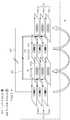
도 6은 본 발명의 일 실시예에 따른 무선전력 송신장치의 구성예의 평면도이다.6 is a plan view of a structural example of a wireless power transmitter according to an embodiment of the present invention.
무선전력 송신장치를 위에서 바라 본 경우, 코일(100)은 도 6에 도시한 것처럼 나타낼 수 있다.When the wireless power transmitter is viewed from above, the
코일(100)은 복수의 셀 그룹을 포함한다. 각 셀 그룹은 복수의 셀을 포함하고, 각 셀 그룹의 복수의 셀이 형성하는 평면은 서로 평행하다.The
각 셀 그룹은 하나 이상의 인접한 셀 그룹을 가진다.Each cell group has one or more adjacent cell groups.
도 6에 도시한 화살표 방향대로 각 셀에 전류가 흐르면, 자기장은 앙페르의 오른나사 법칙에 각 셀들에는 자기장이 들어가거나 나오는 방향으로 형성된다.When current flows in each cell in the direction of the arrow shown in Fig. 6, the magnetic field is formed in the direction in which the magnetic field enters or exits each cell according to Enfer's right-handed law.
각 셀 그룹은 복수의 셀에 의해 자기장이 집중되어 들어가거나 나오는 방향으로 형성할 수 있고, 코일(100)의 위쪽 또는 아래쪽은 반대되는 극성을 이용하여 자기장이 나아가는 방향을 바꿀 수 있다.Each cell group may be formed in a direction in which a magnetic field is concentrated in or out by a plurality of cells, and the upper or lower portion of the
이와 같은 무선전력 송신장치의 코일(100)구조는 자기장의 나가거나 들어오는 방향을 바꾸어 위쪽 또는 아래쪽 방향으로 누출되는 자기장을 최소화하여 인체 유해성을 방지하는데 도움을 줄 수 있고, 동시에 자기장을 집중적으로 형성하여 전력 전송 효율을 극대화시킬 수 있다.
The
또한, 이상에서는 본 발명의 바람직한 실시예에 대하여 도시하고 설명하였지만, 본 발명은 상술한 특정의 실시예에 한정되지 아니하며, 청구범위에서 청구하는 본 발명의 요지를 벗어남이 없이 당해 발명이 속하는 기술분야에서 통상의 지식을 가진 자에 의해 다양한 변형 실시가 가능한 것은 물론이고, 이러한 변형 실시들은 본 발명의 기술적 사상이나 전망으로부터 개별적으로 이해 되어서는 안될 것이다.While the present invention has been particularly shown and described with reference to exemplary embodiments thereof, it is to be understood that the invention is not limited to the disclosed exemplary embodiments, but, on the contrary, It should be understood that various modifications may be made by those skilled in the art without departing from the spirit and scope of the present invention.
10 : 전력 소스
20 : 송신부
21 : 송신 코일
22 : 송신용 공진 코일
30 : 수신부
31 : 수신용 공진 코일
32 : 수신 코일
40 : 정류회로
50 : 부하
100 : 코일
110 : 제1 셀 그룹
120 : 제2 셀 그룹
130 : 제3 셀 그룹
140 : 제4 셀 그룹
150 : 코어10: power source
20: transmitter
21: transmitting coil
22: resonant coil for transmission
30: receiver
31: resonant coil for reception
32: receiving coil
40: rectification circuit
50: load
100: coil
110: first cell group
120: second cell group
130: third cell group
140: fourth cell group
150: core
Claims (9)
Translated fromKorean상기 코일은 복수의 셀 그룹 및 상기 복수의 셀 그룹을 연결하는 코어를 포함하고,
상기 복수의 셀 그룹 각각은 복수의 셀을 포함하고,
각 셀 그룹의 복수의 셀은 상기 복수의 셀에 흐르는 전류에 의해 발생하는 자기장이 동일한 방향으로 형성되도록 구성되고,
각 셀 그룹은 하나 이상의 인접한 셀 그룹을 가지고,
상기 각 셀 그룹 및 상기 코어는 하나의 도선으로 이루어지는 무선전력 송신장치.A wireless power transmitter comprising a coil and a capacitor configured to self-resonate with a wireless power receiver,
The coil includes a plurality of cell groups and a core connecting the plurality of cell groups,
Each of the plurality of cell groups includes a plurality of cells,
The plurality of cells of each cell group are configured such that the magnetic field generated by the current flowing in the plurality of cells is formed in the same direction,
Each cell group has one or more adjacent cell groups,
The cell group and the core is a wireless power transmission device consisting of a single wire.
상기 복수의 셀 그룹 중 상기 코어에 의해 연결되어 인접한 제1 셀 그룹 및 제2 셀 그룹에서 형성되는 자기장의 방향은 서로 다른 것을 특징으로 하는 무선전력 송신장치.The method of claim 1,
And a direction of a magnetic field formed in the first cell group and the second cell group adjacent to each other by the core among the plurality of cell groups is different from each other.
상기 제1 셀 그룹에서 형성되는 자기장의 방향은 상기 제1 셀 그룹의 내부로 들어오는 방향이고, 상기 제2 셀 그룹에서 형성되는 자기장의 방향은 상기 제2 셀 그룹의 내부에서 나오는 방향인 것을 특징으로 하는 무선전력 송신장치.The method of claim 2,
The direction of the magnetic field formed in the first cell group is a direction entering into the first cell group, and the direction of the magnetic field formed in the second cell group is a direction exiting from the inside of the second cell group. Wireless power transmitter.
상기 제1 셀 그룹에서 발생하는 자기장은 상기 제2 셀 그룹에서 발생하는 자기장의 방향을 변경시키는 것을 특징으로 하는 무선전력 송신장치.The method of claim 2,
The magnetic field generated in the first cell group changes the direction of the magnetic field generated in the second cell group.
상기 제1 셀 그룹의 복수의 셀과 상기 제2 셀 그룹의 복수의 셀은 시계 방향 및 반시계 방향으로 교번적으로 감겨지는 것을 특징으로 하는 무선전력 송신장치.The method of claim 2,
And a plurality of cells of the first cell group and a plurality of cells of the second cell group are alternately wound in clockwise and counterclockwise directions.
상기 제1 셀 그룹의 복수의 셀과 상기 제2 셀 그룹의 복수의 셀은 시계 방향 및 반시계 방향으로 교번적으로 감겨져 적층되는 것을 특징으로 하는 무선전력 송신장치.The method of claim 5,
And a plurality of cells of the first cell group and a plurality of cells of the second cell group are alternately wound and stacked in a clockwise direction and a counterclockwise direction.
상기 각 셀 그룹의 복수의 셀간의 간격은 동일한 것을 특징으로 하는 무선전력 송신장치.The method according to claim 1,
And a spacing between a plurality of cells of each cell group is the same.
상기 각 셀 그룹 및 인접한 셀 그룹의 복수의 셀은 상기 코어에 의해 수직으로 연결된 것을 특징으로 하는 무선전력 송신장치.The method of claim 1,
And a plurality of cells of each cell group and an adjacent cell group are vertically connected by the core.
상기 각 셀 그룹의 복수의 셀이 형성하는 평면은 서로 평행한 것을 특징으로 하는 무선전력 송신장치.The method of claim 1,
And a plane formed by the plurality of cells of each cell group is parallel to each other.
Priority Applications (7)
| Application Number | Priority Date | Filing Date | Title |
|---|---|---|---|
| KR1020110105516AKR101262556B1 (en) | 2011-10-14 | 2011-10-14 | Wireless power transmission apparatus |
| TW101137262ATWI470896B (en) | 2011-10-14 | 2012-10-09 | Wireless power transmitter |
| JP2012224755AJP5570570B2 (en) | 2011-10-14 | 2012-10-10 | Wireless power transmitter |
| EP12188069.4AEP2581921B1 (en) | 2011-10-14 | 2012-10-11 | Wireless power transmitter |
| US13/650,802US9300366B2 (en) | 2011-10-14 | 2012-10-12 | Wireless power transmitter |
| CN201210390175.9ACN103051069B (en) | 2011-10-14 | 2012-10-15 | Wireless power transmitter |
| US15/048,211US9923388B2 (en) | 2011-10-14 | 2016-02-19 | Wireless power transmitter |
Applications Claiming Priority (1)
| Application Number | Priority Date | Filing Date | Title |
|---|---|---|---|
| KR1020110105516AKR101262556B1 (en) | 2011-10-14 | 2011-10-14 | Wireless power transmission apparatus |
Publications (2)
| Publication Number | Publication Date |
|---|---|
| KR20130040628A KR20130040628A (en) | 2013-04-24 |
| KR101262556B1true KR101262556B1 (en) | 2013-05-08 |
Family
ID=47010386
Family Applications (1)
| Application Number | Title | Priority Date | Filing Date |
|---|---|---|---|
| KR1020110105516AExpired - Fee RelatedKR101262556B1 (en) | 2011-10-14 | 2011-10-14 | Wireless power transmission apparatus |
Country Status (6)
| Country | Link |
|---|---|
| US (2) | US9300366B2 (en) |
| EP (1) | EP2581921B1 (en) |
| JP (1) | JP5570570B2 (en) |
| KR (1) | KR101262556B1 (en) |
| CN (1) | CN103051069B (en) |
| TW (1) | TWI470896B (en) |
Families Citing this family (22)
| Publication number | Priority date | Publication date | Assignee | Title |
|---|---|---|---|---|
| US9362776B2 (en)* | 2012-11-27 | 2016-06-07 | Qualcomm Incorporated | Wireless charging systems and methods |
| JP6210427B2 (en)* | 2013-08-12 | 2017-10-11 | 東芝ライテック株式会社 | Power supply device and lighting device |
| KR102108546B1 (en)* | 2013-09-16 | 2020-05-11 | 삼성전자주식회사 | Resonator device with improved isoalation for stable wireless power transfer |
| CN106575884A (en)* | 2014-04-26 | 2017-04-19 | Elix无线充电系统公司 | Magnetic field configuration for a wireless energy transfer system |
| BR112017002136A2 (en) | 2014-08-03 | 2017-11-21 | Pogotec Inc | ? electronic device system? |
| US9635222B2 (en) | 2014-08-03 | 2017-04-25 | PogoTec, Inc. | Wearable camera systems and apparatus for aligning an eyewear camera |
| TW201724703A (en)* | 2014-12-15 | 2017-07-01 | 帕戈技術股份有限公司 | Wireless power base unit and a system and method for wirelessly charging distance separated electronic devices |
| TWI596937B (en) | 2014-12-23 | 2017-08-21 | 帕戈技術股份有限公司 | Wearable camera, system for providing wireless power, method for wirelessly providing power, and method for processing image |
| KR102363641B1 (en)* | 2015-01-14 | 2022-02-17 | 삼성전자주식회사 | Wearable device |
| JP2018521345A (en) | 2015-06-10 | 2018-08-02 | ポゴテック インクPogoTec, Inc. | Eyewear with magnetic track for wearable electronics |
| US10481417B2 (en) | 2015-06-10 | 2019-11-19 | PogoTec, Inc. | Magnetic attachment mechanism for electronic wearable device |
| TW201729610A (en) | 2015-10-29 | 2017-08-16 | 帕戈技術股份有限公司 | Hearing aid adapted for wireless power reception |
| KR101804410B1 (en)* | 2015-12-17 | 2017-12-04 | 엘지이노텍 주식회사 | Transmitting Coil Module For Wireless Power Transmitter |
| US11558538B2 (en) | 2016-03-18 | 2023-01-17 | Opkix, Inc. | Portable camera system |
| JP6437954B2 (en)* | 2016-06-02 | 2018-12-12 | パナソニック株式会社 | Wireless power supply method |
| KR101846715B1 (en) | 2016-09-26 | 2018-04-10 | 연세대학교 산학협력단 | Apparatus for transmitting wireless power, apparatus for receiving wireless power and system for transmitting wireless power |
| US10863060B2 (en) | 2016-11-08 | 2020-12-08 | PogoTec, Inc. | Smart case for electronic wearable device |
| DE102017117418A1 (en)* | 2017-08-01 | 2019-02-07 | Feaam Gmbh | Primary-side charging device, secondary-side charging device and method for charging a battery for a vehicle with an electric drive |
| CN108199436A (en)* | 2018-01-15 | 2018-06-22 | 杭州电子科技大学 | Wireless charging system |
| KR20190138536A (en)* | 2018-06-05 | 2019-12-13 | 주식회사 히타치엘지 데이터 스토리지 코리아 | Multiple coils for transmitting power wirelessly |
| JP2020009972A (en)* | 2018-07-11 | 2020-01-16 | 株式会社東芝 | Inductor unit, wireless power transfer system and electric vehicle |
| WO2020102237A1 (en) | 2018-11-13 | 2020-05-22 | Opkix, Inc. | Wearable mounts for portable camera |
Citations (2)
| Publication number | Priority date | Publication date | Assignee | Title |
|---|---|---|---|---|
| JP2009525715A (en) | 2006-01-31 | 2009-07-09 | エルエス ケーブル リミテッド | Non-contact charging device provided with coil array, non-contact charging system and charging method |
| WO2010118191A1 (en) | 2009-04-08 | 2010-10-14 | Access Business Group International Llc | Selectable coil array |
Family Cites Families (27)
| Publication number | Priority date | Publication date | Assignee | Title |
|---|---|---|---|---|
| JP3334395B2 (en)* | 1995-01-17 | 2002-10-15 | 株式会社豊田自動織機 | Non-contact power supply |
| JP3259717B2 (en) | 1999-08-20 | 2002-02-25 | 株式会社村田製作所 | Multilayer inductor |
| GB2399228B (en)* | 2002-05-13 | 2006-01-04 | Splashpower Ltd | Inductive power transfer system having uniform coupling |
| US7406623B2 (en)* | 2003-09-29 | 2008-07-29 | Hitachi Computer Peripherals Co., Ltd. | DC backup power supply system and disk array using same |
| US7262680B2 (en)* | 2004-02-27 | 2007-08-28 | Illinois Institute Of Technology | Compact inductor with stacked via magnetic cores for integrated circuits |
| EP1817230A1 (en)* | 2004-09-21 | 2007-08-15 | Saf-t-Glo Limited | Aircraft emergency lighting system |
| US8169185B2 (en) | 2006-01-31 | 2012-05-01 | Mojo Mobility, Inc. | System and method for inductive charging of portable devices |
| CN101523693B (en)* | 2006-08-04 | 2012-05-23 | Sk化学株式会社 | Induction coil for cordless energy charging and data transfer |
| CN103633745B (en)* | 2007-03-27 | 2015-09-09 | 麻省理工学院 | Method for wireless energy transfer |
| US8283812B2 (en)* | 2007-10-09 | 2012-10-09 | Powermat Technologies, Ltd. | Inductive power providing system having moving outlets |
| WO2009046720A1 (en)* | 2007-10-11 | 2009-04-16 | Region Hovedstaden V/Herlev Hospital | An electroporation device for improved electrical field control |
| JPWO2009066433A1 (en) | 2007-11-21 | 2011-03-31 | パナソニック株式会社 | Coil parts |
| TW200943664A (en)* | 2008-04-01 | 2009-10-16 | Fenq-Lin Jenq | Non-contact electric power supply system |
| US8965461B2 (en)* | 2008-05-13 | 2015-02-24 | Qualcomm Incorporated | Reverse link signaling via receive antenna impedance modulation |
| US7893564B2 (en)* | 2008-08-05 | 2011-02-22 | Broadcom Corporation | Phased array wireless resonant power delivery system |
| US8421274B2 (en)* | 2008-09-12 | 2013-04-16 | University Of Pittsburgh-Of The Commonwealth System Of Higher Education | Wireless energy transfer system |
| US8772973B2 (en)* | 2008-09-27 | 2014-07-08 | Witricity Corporation | Integrated resonator-shield structures |
| US9601261B2 (en)* | 2008-09-27 | 2017-03-21 | Witricity Corporation | Wireless energy transfer using repeater resonators |
| TWM367734U (en)* | 2009-05-21 | 2009-11-01 | Plus Meditech Co Ltd | Protective equipment for wrist |
| US8460816B2 (en)* | 2009-10-08 | 2013-06-11 | Etymotic Research, Inc. | Rechargeable battery assemblies and methods of constructing rechargeable battery assemblies |
| JP5077340B2 (en) | 2009-12-25 | 2012-11-21 | トヨタ自動車株式会社 | Non-contact power receiving apparatus and manufacturing method thereof |
| US8766486B2 (en)* | 2010-01-28 | 2014-07-01 | Youhua Technology (Shenzhen) Co., Ltd | Non-resonance wireless power device |
| KR101718723B1 (en)* | 2010-04-08 | 2017-03-22 | 삼성전자주식회사 | Laptop computer system with wireless power transform function |
| JP4602471B1 (en)* | 2010-04-14 | 2010-12-22 | 和征 榊原 | Battery pack and battery pack system |
| US8130067B2 (en)* | 2010-05-11 | 2012-03-06 | Texas Instruments Incorporated | High frequency semiconductor transformer |
| CN201749754U (en)* | 2010-08-04 | 2011-02-16 | 北京美新华微电子技术有限公司 | Wireless power transmission coil |
| EP2642630B1 (en)* | 2011-03-25 | 2016-06-29 | Sanyo Electric Co., Ltd. | Battery system, electric-powered vehicle, mobile object, power storage device, power supply device |
- 2011
- 2011-10-14KRKR1020110105516Apatent/KR101262556B1/ennot_activeExpired - Fee Related
- 2012
- 2012-10-09TWTW101137262Apatent/TWI470896B/ennot_activeIP Right Cessation
- 2012-10-10JPJP2012224755Apatent/JP5570570B2/ennot_activeExpired - Fee Related
- 2012-10-11EPEP12188069.4Apatent/EP2581921B1/enactiveActive
- 2012-10-12USUS13/650,802patent/US9300366B2/enactiveActive
- 2012-10-15CNCN201210390175.9Apatent/CN103051069B/ennot_activeExpired - Fee Related
- 2016
- 2016-02-19USUS15/048,211patent/US9923388B2/enactiveActive
Patent Citations (2)
| Publication number | Priority date | Publication date | Assignee | Title |
|---|---|---|---|---|
| JP2009525715A (en) | 2006-01-31 | 2009-07-09 | エルエス ケーブル リミテッド | Non-contact charging device provided with coil array, non-contact charging system and charging method |
| WO2010118191A1 (en) | 2009-04-08 | 2010-10-14 | Access Business Group International Llc | Selectable coil array |
Also Published As
| Publication number | Publication date |
|---|---|
| TW201322582A (en) | 2013-06-01 |
| JP2013090564A (en) | 2013-05-13 |
| EP2581921B1 (en) | 2017-11-29 |
| KR20130040628A (en) | 2013-04-24 |
| EP2581921A3 (en) | 2015-04-22 |
| TWI470896B (en) | 2015-01-21 |
| JP5570570B2 (en) | 2014-08-13 |
| EP2581921A2 (en) | 2013-04-17 |
| US20160172871A1 (en) | 2016-06-16 |
| US9923388B2 (en) | 2018-03-20 |
| CN103051069B (en) | 2015-04-29 |
| US9300366B2 (en) | 2016-03-29 |
| CN103051069A (en) | 2013-04-17 |
| US20130093255A1 (en) | 2013-04-18 |
Similar Documents
| Publication | Publication Date | Title |
|---|---|---|
| KR101262556B1 (en) | Wireless power transmission apparatus | |
| KR101349557B1 (en) | Apparatus for receiving wireless power and method for deliveringng wireless power | |
| CN103051068B (en) | Wireless power repeater | |
| KR101189298B1 (en) | Resonant coil wireless power transmission apparatus having the same | |
| KR101382920B1 (en) | Apparatus for transmitting wireless power | |
| Khan et al. | Long range wireless power transfer via magnetic resonance | |
| US10491043B2 (en) | Resonant coil, wireless power transmitter using the same, wireless power receiver using the same | |
| KR101976613B1 (en) | Wireless power receiver | |
| KR101349448B1 (en) | Apparatus for delivering wireless power | |
| KR101327024B1 (en) | Apparatus for transmitting wireless power and system for transmitting wireless power | |
| KR20120116801A (en) | A wireless power transmission circuit, a wireless power transmitter and receiver | |
| KR101305790B1 (en) | Apparatus for transmitting wireless power and apparatus for receiving wireless power | |
| KR101294581B1 (en) | Apparatus for delivering wireless power and terminal | |
| US9634731B2 (en) | Wireless power transmitter | |
| CN110277646A (en) | Stereo Antenna for Wireless Charging of Electronic Devices | |
| KR20130068646A (en) | Apparatus for transmitting wireless power and system for transmitting wireless power | |
| KR101786086B1 (en) | A transmitter and receiver for wireless power transmission with minimized flux linkage | |
| KR101438888B1 (en) | Apparatus for transmitting wireless power and system for transmitting wireless power | |
| KR20120116799A (en) | A coil for wireless power transmission and a transmitter and receiver for the same |
Legal Events
| Date | Code | Title | Description |
|---|---|---|---|
| A201 | Request for examination | ||
| PA0109 | Patent application | St.27 status event code:A-0-1-A10-A12-nap-PA0109 | |
| PA0201 | Request for examination | St.27 status event code:A-1-2-D10-D11-exm-PA0201 | |
| E902 | Notification of reason for refusal | ||
| PE0902 | Notice of grounds for rejection | St.27 status event code:A-1-2-D10-D21-exm-PE0902 | |
| P11-X000 | Amendment of application requested | St.27 status event code:A-2-2-P10-P11-nap-X000 | |
| P13-X000 | Application amended | St.27 status event code:A-2-2-P10-P13-nap-X000 | |
| E701 | Decision to grant or registration of patent right | ||
| PE0701 | Decision of registration | St.27 status event code:A-1-2-D10-D22-exm-PE0701 | |
| PG1501 | Laying open of application | St.27 status event code:A-1-1-Q10-Q12-nap-PG1501 | |
| GRNT | Written decision to grant | ||
| PR0701 | Registration of establishment | St.27 status event code:A-2-4-F10-F11-exm-PR0701 | |
| PR1002 | Payment of registration fee | St.27 status event code:A-2-2-U10-U11-oth-PR1002 Fee payment year number:1 | |
| PG1601 | Publication of registration | St.27 status event code:A-4-4-Q10-Q13-nap-PG1601 | |
| PN2301 | Change of applicant | St.27 status event code:A-5-5-R10-R13-asn-PN2301 St.27 status event code:A-5-5-R10-R11-asn-PN2301 | |
| PR1001 | Payment of annual fee | St.27 status event code:A-4-4-U10-U11-oth-PR1001 Fee payment year number:4 | |
| R18-X000 | Changes to party contact information recorded | St.27 status event code:A-5-5-R10-R18-oth-X000 | |
| FPAY | Annual fee payment | Payment date:20170405 Year of fee payment:5 | |
| PR1001 | Payment of annual fee | St.27 status event code:A-4-4-U10-U11-oth-PR1001 Fee payment year number:5 | |
| FPAY | Annual fee payment | Payment date:20180409 Year of fee payment:6 | |
| PR1001 | Payment of annual fee | St.27 status event code:A-4-4-U10-U11-oth-PR1001 Fee payment year number:6 | |
| R18-X000 | Changes to party contact information recorded | St.27 status event code:A-5-5-R10-R18-oth-X000 | |
| P22-X000 | Classification modified | St.27 status event code:A-4-4-P10-P22-nap-X000 | |
| P22-X000 | Classification modified | St.27 status event code:A-4-4-P10-P22-nap-X000 | |
| FPAY | Annual fee payment | Payment date:20190411 Year of fee payment:7 | |
| PR1001 | Payment of annual fee | St.27 status event code:A-4-4-U10-U11-oth-PR1001 Fee payment year number:7 | |
| R18-X000 | Changes to party contact information recorded | St.27 status event code:A-5-5-R10-R18-oth-X000 | |
| PC1903 | Unpaid annual fee | St.27 status event code:A-4-4-U10-U13-oth-PC1903 Not in force date:20200503 Payment event data comment text:Termination Category : DEFAULT_OF_REGISTRATION_FEE | |
| PC1903 | Unpaid annual fee | St.27 status event code:N-4-6-H10-H13-oth-PC1903 Ip right cessation event data comment text:Termination Category : DEFAULT_OF_REGISTRATION_FEE Not in force date:20200503 | |
| PN2301 | Change of applicant | St.27 status event code:A-5-5-R10-R13-asn-PN2301 St.27 status event code:A-5-5-R10-R11-asn-PN2301 | |
| P22-X000 | Classification modified | St.27 status event code:A-4-4-P10-P22-nap-X000 | |
| P22-X000 | Classification modified | St.27 status event code:A-4-4-P10-P22-nap-X000 |