KR101262340B1 - Apparatus for providing system information and method thereof - Google Patents
Apparatus for providing system information and method thereofDownload PDFInfo
- Publication number
- KR101262340B1 KR101262340B1KR1020110127193AKR20110127193AKR101262340B1KR 101262340 B1KR101262340 B1KR 101262340B1KR 1020110127193 AKR1020110127193 AKR 1020110127193AKR 20110127193 AKR20110127193 AKR 20110127193AKR 101262340 B1KR101262340 B1KR 101262340B1
- Authority
- KR
- South Korea
- Prior art keywords
- network
- terminal
- base station
- cell
- system information
- Prior art date
- Legal status (The legal status is an assumption and is not a legal conclusion. Google has not performed a legal analysis and makes no representation as to the accuracy of the status listed.)
- Active
Links
- 238000000034methodMethods0.000titleclaimsabstractdescription25
- 238000013507mappingMethods0.000claimsabstractdescription23
- 238000012545processingMethods0.000claimsdescription56
- 230000007704transitionEffects0.000claimsdescription14
- 230000005540biological transmissionEffects0.000claimsdescription10
- 239000000284extractSubstances0.000abstractdescription5
- 238000011144upstream manufacturingMethods0.000abstract1
- 238000010586diagramMethods0.000description9
- 238000004891communicationMethods0.000description4
- PWHULOQIROXLJO-UHFFFAOYSA-NManganeseChemical compound[Mn]PWHULOQIROXLJO-UHFFFAOYSA-N0.000description1
- 238000011161developmentMethods0.000description1
- 238000005516engineering processMethods0.000description1
- 230000007774longtermEffects0.000description1
- 229910052748manganeseInorganic materials0.000description1
- 239000011572manganeseSubstances0.000description1
- 238000010295mobile communicationMethods0.000description1
- 230000003287optical effectEffects0.000description1
- 238000003672processing methodMethods0.000description1
Images


Classifications
- H—ELECTRICITY
- H04—ELECTRIC COMMUNICATION TECHNIQUE
- H04W—WIRELESS COMMUNICATION NETWORKS
- H04W48/00—Access restriction; Network selection; Access point selection
- H04W48/08—Access restriction or access information delivery, e.g. discovery data delivery
- H04W48/10—Access restriction or access information delivery, e.g. discovery data delivery using broadcasted information
- H—ELECTRICITY
- H04—ELECTRIC COMMUNICATION TECHNIQUE
- H04W—WIRELESS COMMUNICATION NETWORKS
- H04W36/00—Hand-off or reselection arrangements
- H04W36/0005—Control or signalling for completing the hand-off
- H04W36/0009—Control or signalling for completing the hand-off for a plurality of users or terminals, e.g. group communication or moving wireless networks
- H—ELECTRICITY
- H04—ELECTRIC COMMUNICATION TECHNIQUE
- H04W—WIRELESS COMMUNICATION NETWORKS
- H04W36/00—Hand-off or reselection arrangements
- H04W36/0005—Control or signalling for completing the hand-off
- H04W36/0055—Transmission or use of information for re-establishing the radio link
- H04W36/0066—Transmission or use of information for re-establishing the radio link of control information between different types of networks in order to establish a new radio link in the target network
- H—ELECTRICITY
- H04—ELECTRIC COMMUNICATION TECHNIQUE
- H04W—WIRELESS COMMUNICATION NETWORKS
- H04W36/00—Hand-off or reselection arrangements
- H04W36/04—Reselecting a cell layer in multi-layered cells
- H—ELECTRICITY
- H04—ELECTRIC COMMUNICATION TECHNIQUE
- H04W—WIRELESS COMMUNICATION NETWORKS
- H04W36/00—Hand-off or reselection arrangements
- H04W36/06—Reselecting a communication resource in the serving access point
- H—ELECTRICITY
- H04—ELECTRIC COMMUNICATION TECHNIQUE
- H04W—WIRELESS COMMUNICATION NETWORKS
- H04W48/00—Access restriction; Network selection; Access point selection
- H04W48/08—Access restriction or access information delivery, e.g. discovery data delivery
- H04W48/12—Access restriction or access information delivery, e.g. discovery data delivery using downlink control channel
- H—ELECTRICITY
- H04—ELECTRIC COMMUNICATION TECHNIQUE
- H04W—WIRELESS COMMUNICATION NETWORKS
- H04W36/00—Hand-off or reselection arrangements
- H04W36/08—Reselecting an access point
- H04W36/087—Reselecting an access point between radio units of access points
Landscapes
- Engineering & Computer Science (AREA)
- Computer Networks & Wireless Communication (AREA)
- Signal Processing (AREA)
- Computer Security & Cryptography (AREA)
- Mobile Radio Communication Systems (AREA)
Abstract
Translated fromKoreanDescription
Translated fromKorean본 발명은 시스템 정보 제공 장치 및 그 방법에 관한 것이다.The present invention relates to a system information providing apparatus and a method thereof.
최근 이동 통신 기술의 발달에 따라 이종망, 예를 들면, UTRAN(UMTS(Universal Mobile Telecommunications Systems) Terrestrial Radio Access Network)과 LTE(Long Term Evolution)망이 오버레이(overlay)될 수 있다.With the recent development of mobile communication technology, heterogeneous networks, for example, Universal Mobile Telecommunications Systems (UTRAN) Terrestrial Radio Access Network (UTRAN) and Long Term Evolution (LTE) networks may be overlayed.
단말이 이종망의 경계 주변에 위치해 있는 경우, 단말이 현재 연결되어 있는 망의 서비스 지역을 벗어날 수 있고, 이에 따라 단말의 신호 품질이 나빠질 수 있다. 따라서, 이종망의 경계 주변에 위치해 있는 단말이 현재 연결되어 있는 망에서 다른 망으로 천이(Redirection)할 필요가 있다.When the terminal is located near the boundary of the heterogeneous network, the terminal may leave the service area of the network to which it is currently connected, and thus the signal quality of the terminal may be deteriorated. Therefore, a terminal located near the boundary of the heterogeneous network needs to redirection from the currently connected network to another network.
또한, 현재 UTRAN(UMTS Radio Access Network)은 회선 교환(CS: Circuit Switch) 방식과 패킷 교환(PS: Packet Switch) 방식을 모두 지원하고 있으나 LTE(Long Term Evolution)망에서는 IMS(IP Multimedia Subsystem) 기반으로 음성 호를 지원하고는 있지만, 현재 대부분의 사업자들이 IMS를 도입하지 않고 있는 실정이다. 이에 따라, LTE망 표준에서는 음성 호를 지원하기 위해서 UTRAN으로 천이하여 음성 호를 지원하는 CS 폴백(Circuit Switched Fallback) 서비스를 제안하고 있다.In addition, UTRAN (UMTS Radio Access Network) supports both Circuit Switch (CS) and Packet Switch (PS) methods, but based on Long Multimedia Evolution (LTE) network based on IMS (IP Multimedia Subsystem) Although it supports voice calls, most operators do not adopt IMS. Accordingly, the LTE network standard proposes a CS Fallback (Circuit Switched Fallback) service that transitions to UTRAN to support voice calls to support voice calls.
한편, LTE망의 셀 크기가 UTRAN의 셀 크기보다 커서 LTE망의 셀과 UTRAN의 셀이 중첩(overlay)되는 경우 LTE망의 셀에 중첩되는 UTRAN의 셀의 수가 많게 된다.On the other hand, when the cell size of the LTE network is larger than the cell size of the UTRAN, when the cells of the LTE network and the UTRAN overlap (overlay), the number of cells of the UTRAN overlapping the cells of the LTE network becomes large.
이와 같이, 이종망의 경계 주변에서 망의 천이가 발생되거나 또는 LTE망에서 음성 호의 지원을 위해 UTRAN으로의 천이가 발생되는 경우, 천이 전의 망에서는 천이될 망에 대한 시스템 정보를 제공하는데, 이 때 단말기가 속한 천이 전의 망의 셀에 중첩되는 천이되는 망의 셀 모두에 대한 시스템 정보를 천이 전의 망으로 전달함으로써 불필요한 시스템 정보를 다수 전송해야 하고, 이로 인해 단말기가 데이터를 받는데 필요한 지연이 늘어나므로 단말기가 천이하는데 더 많은 지연이 필요하게 되는 문제점이 있다.As such, when a network transition occurs around a boundary of a heterogeneous network or a transition to UTRAN for support of a voice call in an LTE network, the network information before the transition provides system information about the network to be transitioned. By transmitting system information about all cells of the network to be transitioned to the cells of the network before the terminal to which the terminal belongs to the network before the transition, a large amount of unnecessary system information must be transmitted. This increases the delay required for the terminal to receive data. There is a problem that more delay is required to transition.
본 발명이 이루고자 하는 기술적 과제는 신호 처리 지연이 감소될 수 있는 시스템 정보 제공 장치 및 그 방법을 제공하는 것이다.It is an object of the present invention to provide an apparatus and method for providing system information in which signal processing delay can be reduced.
본 발명의 한 특징에 따른 시스템 정보 제공 장치는,System information providing apparatus according to an aspect of the present invention,
중첩되어 있는 이기종 망에서 시스템 정보를 제공하는 장치로서, 제1 망에 접속되어 제2 망으로 천이되는 단말기로부터 상향 신호를 수신하여 상기 단말기에 가장 근접해 있는 상기 제1 망의 기지국을 판단하는 위치 판단부; 상기 제1 망의 기지국에 지리적으로 인접해 있는 적어도 하나의 제2 망의 기지국을 매핑하여 저장하는 매핑 테이블; 및 상기 위치 판단부에 의해 판단되는 상기 제1 망의 기지국에 대해 상기 매핑 테이블에 매핑되어 있는 적어도 하나의 상기 제2 망의 기지국 정보를 추출하고, 추출되는 상기 제2 망의 기지국에 해당하는 시스템 정보를 상기 단말기로 전송하는 신호 처리부를 포함한다.An apparatus for providing system information in an overlapping heterogeneous network, comprising: determining a base station of the first network closest to the terminal by receiving an uplink signal from a terminal connected to a first network and transitioning to a second network; part; A mapping table for mapping and storing base stations of at least one second network geographically adjacent to the base stations of the first network; And extracting at least one base station information of the second network mapped to the mapping table with respect to the base station of the first network determined by the position determining unit and corresponding to the extracted base station of the second network. It includes a signal processor for transmitting information to the terminal.
여기서, 상기 제2 망의 셀 크기가 상기 제1 망의 셀 크기보다 작아서 상기 제1 망의 하나의 셀 내에 복수의 상기 제2 망의 셀이 포함되어 중첩되어 있으며, 상기 제1 망의 하나의 셀에는 복수의 제1 망 RRH(Remote Radio Head)가 포함되어 있고 상기 제2 망의 하나의 셀에는 하나의 제2 망 RRH가 포함되어 있는 것을 특징으로 한다.Here, the cell size of the second network is smaller than that of the first network so that a plurality of cells of the second network are included and overlapped in one cell of the first network. The cell includes a plurality of first network remote radio heads (RRHs), and one cell of the second network includes one second network RRH.
또한, 상기 시스템 정보 제공 장치는 상기 단말기로부터 수신되는 상향 신호 중 파일롯 송신신호(Sounding Reference Signal, SRS)를 추출하는 입력부; 및 상기 신호 처리부에서 전달되는 시스템 정보를 상기 위치 판단부에서 판단되는 상기 제1 망의 기지국을 통해 상기 단말기로 전송하는 출력부를 더 포함하며, 상기 위치 판단부는 상기 입력부에서 추출되는 파일롯 송신신호에 기초하여 상기 단말기의 위치를 판단하는 것을 특징으로 한다.In addition, the system information providing apparatus includes an input unit for extracting a pilot transmission signal (Sounding Reference Signal, SRS) of the uplink signal received from the terminal; And an output unit for transmitting the system information transmitted from the signal processor to the terminal through the base station of the first network determined by the position determiner, wherein the position determiner is based on a pilot transmission signal extracted from the input unit. It is characterized in that for determining the position of the terminal.
또한, 상기 매핑 테이블은 상기 제1 망의 기지국에 대해 적어도 하나의 제2 망의 기지국의 식별 정보를 저장하는 것을 특징으로 한다.The mapping table may store identification information of at least one base station of the second network with respect to the base station of the first network.
또한, 상기 위치 판단부는 상기 단말기가 상기 제1 망의 경계 지역에 위치하여 신호 세기가 약해지는 경우 또는 음성 호 처리를 위해 상기 제2 망으로 천이되는 경우에 상기 단말기의 위치를 판단하는 것을 특징으로 한다.The location determining unit may determine the location of the terminal when the terminal is located at a boundary of the first network and the signal strength is weakened or when the terminal is transitioned to the second network for voice call processing. do.
본 발명의 다른 특징에 따른 시스템 정보 제공 방법은,System information providing method according to another aspect of the present invention,
제1 망에 접속되어 제2 망으로 천이되는 단말기로부터 상향 신호를 수신하는 단계; 상기 상향 신호에 기초하여 상기 단말기에 가장 근접해 있는 상기 제1 망의 기지국을 판단하는 단계; 판단되는 상기 제1 망의 기지국에 대해 매핑 테이블-여기서 매핑 테이블은 상기 제1 망의 기지국에 지리적으로 인접해 있는 적어도 하나의 제2 망의 기지국을 매핑하여 저장하고 있음-에 매핑되어 있는 적어도 하나의 상기 제2 망의 기지국 정보를 추출하는 단계; 및 추출되는 적어도 하나의 상기 제2 망의 기지국에 해당하는 시스템 정보를 상기 단말기로 전송하는 단계를 포함한다.Receiving an uplink signal from a terminal connected to a first network and transitioning to a second network; Determining a base station of the first network closest to the terminal based on the uplink signal; At least one mapped to a mapping table for the base station of the first network determined, wherein the mapping table maps and stores the base stations of at least one second network geographically adjacent to the base station of the first network. Extracting base station information of the second network of the network; And transmitting system information corresponding to the extracted base station of the at least one second network to the terminal.
여기서, 상기 판단하는 단계에서, 상기 단말기로부터 수신되는 상향 신호 중 파일롯 송신신호(Sounding Reference Signal, SRS)에 기초하여 상기 단말기의 위치를 판단하는 것을 특징으로 한다.In the determining, the position of the terminal may be determined based on a pilot transmission signal (Sounding Reference Signal, SRS) among the uplink signals received from the terminal.
본 발명에 따르면, 단말기가 위치한 LTE RRH에 지리적으로 인접해 있는 UTRAN의 셀의 시스템 정보만을 전송받으므로, 종래에 비해 불필요한 시스템 정보 전송을 수신하지 않아 신호 처리 지연이 감소될 수 있다.According to the present invention, since only system information of a cell of the UTRAN that is geographically adjacent to the LTE RRH in which the terminal is located is received, signal processing delay can be reduced by not receiving unnecessary system information transmission as compared with the conventional art.
도 1은 본 발명의 실시예가 적용되는 LTE망의 구성도이다.
도 2는 LTE망의 셀에 대한 일반적인 구성을 도시한 도면이다.
도 3은 일반적인 LTE망의 셀과 이에 중첩되는 UTRAN의 셀을 도시한 도면이다.
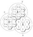
도 4는 본 발명의 실시예에 따른 시스템 정보를 제공하는 방법이 적용되는 가상화된 LTE 셀과 UTRAN 셀 구조를 도시한 도면이다.
도 5는 본 발명의 실시예에 따른 시스템 정보를 제공하는 신호 처리 장치의 구성을 도시한 도면이다.
도 6은 도 4에 도시된 매핑 테이블의 구조를 도시한 도면이다.
도 7은 본 발명의 실시예에 따른 시스템 정보를 제공하는 방법의 흐름도이다.1 is a block diagram of an LTE network to which an embodiment of the present invention is applied.
2 illustrates a general configuration of a cell of an LTE network.
3 is a diagram illustrating a cell of a general LTE network and a cell of UTRAN overlapping it.
4 is a diagram illustrating a virtualized LTE cell and UTRAN cell structure to which a method for providing system information according to an embodiment of the present invention is applied.
5 is a diagram illustrating a configuration of a signal processing apparatus for providing system information according to an exemplary embodiment of the present invention.
FIG. 6 is a diagram illustrating the structure of a mapping table shown in FIG. 4.
7 is a flowchart of a method for providing system information according to an embodiment of the present invention.
아래에서는 첨부한 도면을 참고로 하여 본 발명의 실시예에 대하여 본 발명이 속하는 기술 분야에서 통상의 지식을 가진 자가 용이하게 실시할 수 있도록 상세히 설명한다. 그러나 본 발명은 여러 가지 상이한 형태로 구현될 수 있으며 여기에서 설명하는 실시예에 한정되지 않는다. 그리고 도면에서 본 발명을 명확하게 설명하기 위해서 설명과 관계없는 부분은 생략하였으며, 명세서 전체를 통하여 유사한 부분에 대해서는 유사한 도면 부호를 붙였다.DETAILED DESCRIPTION Hereinafter, exemplary embodiments of the present invention will be described in detail with reference to the accompanying drawings so that those skilled in the art may easily implement the present invention. The present invention may, however, be embodied in many different forms and should not be construed as limited to the embodiments set forth herein. In the drawings, parts irrelevant to the description are omitted in order to clearly describe the present invention, and like reference numerals designate like parts throughout the specification.
명세서 전체에서, 어떤 부분이 어떤 구성요소를 "포함"한다고 할 때, 이는 특별히 반대되는 기재가 없는 한 다른 구성요소를 제외하는 것이 아니라 다른 구성요소를 더 포함할 수 있는 것을 의미한다. 또한, 명세서에 기재된 "…부", "…기", "모듈" 등의 용어는 적어도 하나의 기능이나 동작을 처리하는 단위를 의미하며, 이는 하드웨어나 소프트웨어 또는 하드웨어 및 소프트웨어의 결합으로 구현될 수 있다.Throughout the specification, when a part is said to "include" a certain component, it means that it can further include other components, without excluding other components unless specifically stated otherwise. Also, the terms " part, "" module," and " module ", etc. in the specification mean a unit for processing at least one function or operation and may be implemented by hardware or software or a combination of hardware and software have.
본 명세서에서 단말기(terminal)는 이동국(Mobile Station, MS), 이동 단말(Mobile Terminal, MT), 가입자국(Subscriber Station, SS), 휴대 가입자국(Portable Subscriber Station, PSS), 사용자 장치(User Equipment, UE), 접근 단말(Access Terminal, AT) 등을 지칭할 수도 있고, 단말, 이동 단말, 가입자국, 휴대 가입자 국, 사용자 장치, 접근 단말 등의 전부 또는 일부의 기능을 포함할 수도 있다.In the present specification, a terminal is a mobile station (MS), a mobile terminal (MT), a subscriber station (SS), a portable subscriber station (PSS), a user device (User Equipment). It may also refer to a user equipment (UE), an access terminal (AT), and the like, and may include all or some functions of a terminal, a mobile terminal, a subscriber station, a portable subscriber station, a user device, an access terminal, and the like.
이제 도면을 참고하여 본 발명의 실시예에 따른 시스템 정보 제공 방법 및 그 방법을 수행하는 신호 처리 장치에 대해 설명한다.A system information providing method and a signal processing apparatus for performing the method according to an embodiment of the present invention will now be described with reference to the drawings.
도 1은 본 발명의 실시예가 적용되는 LTE망의 구성도이다.1 is a block diagram of an LTE network to which an embodiment of the present invention is applied.
도 1을 참고하면, LTE망은 무선 신호 처리 장치(radio unit, RU)(100), 디지털 신호 처리 장치(digital unit, DU)(200) 및 코어 시스템(300)을 포함한다. 무선 신호 처리 장치(100)및 디지털 신호 처리 장치(200)는 무선 통신의 신호 처리 시스템을 이룬다.Referring to FIG. 1, the LTE network includes a radio unit (RU) 100, a
무선 신호 처리 장치(100)는 무선 신호를 처리하는 부분으로서 디지털 신호 처리 장치(200)로부터 수신한 디지털 신호를 주파수 대역에 따라 무선 주파수(radio frequency, RF) 신호로 변환하고 증폭한다. 무선 신호 처리 장치(100)는 디지털 신호 처리 장치(200)에 복수 개(110, 120, 130)가 연결되어 있으며, 각 무선 신호 처리 장치(100)는 서비스 대상 지역, 즉 셀에 설치된다. 무선 신호 처리 장치(100)와 디지털 신호 처리 장치(200)는 광케이블로 연결되어 있을 수 있다.The wireless
디지털 신호 처리 장치(200)는 무선 디지털 신호를 암호화 및 복호화 등의 처리를 수행하며, 코어 시스템(300)에 연결되어 있다. 디지털 신호 처리 장치(200)는 무선 신호 처리 장치(100)와 달리 서비스 대상 지역에 설치되는 것이 아니라 주로 통신 국사에 집중화되어 설치되는 서버로서, 가상화된 기지국이다. 디지털 신호 처리 장치(200)는 복수의 무선 신호 처리 장치(100)와 신호를 송수신한다.The digital
기존의 통신 기지국은 이러한 무선 신호 처리 장치(100) 및 디지털 신호 처리 장치(200) 각각에 대응하는 처리부를 하나의 물리적 시스템 내에 포함하고, 하나의 물리적 시스템이 서비스 대상 지역에 설치된다. 그러나, 본 발명의 실시예에 따른 LTE망은 무선 신호 처리 장치(100) 및 디지털 신호 처리 장치(200)를 물리적으로 분리하고, 무선 신호 처리 장치(100)만 서비스 대상 지역에 설치된다.The existing communication base station includes a processing unit corresponding to each of the wireless
코어 시스템(300)은 디지털 신호 처리 장치(200)와 외부 망의 접속을 처리하며, 교환기(도시하지 않음) 등을 포함한다.The
도 2는 LTE망의 셀에 대한 일반적인 구성을 도시한 도면이다.2 illustrates a general configuration of a cell of an LTE network.
도 2를 참고하면, LTE망의 셀(10, 20, 30)은 각각 복수의 무선 신호 처리 장치(100)를 포함한다. 무선 신호 처리 장치(100)는 매크로 무선 신호 처리 장치(macro RU)(111, 121)(macro RU) 및 복수의 협력 무선 신호 처리 장치(cooperative RU)(112, 113, 114, 115, 116, 117, 122, 123, 124, 125, 126, 127)를 포함한다.Referring to FIG. 2, the
매크로 무선 신호 처리 장치(111, 121)는 셀(10, 20)의 주요 통신 처리를 관장하며, 고출력의 전력으로 셀(10, 20) 내의 모든 단말에게 신호를 전송한다. 협력 무선 신호 처리 장치(112-117, 122-127)는 매크로 무선 신호 처리 장치(111, 121)의 출력보다 소출력의 전력으로 자신의 주변에 있는 단말에게 신호를 전송한다.The macro radio
하나의 셀(10)에는 적어도 하나의 매크로 무선 신호 처리 장치(111) 및 복수의 협력 무선 신호 처리 장치(112-117)가 포함되어 있다. 이러한 복수의 셀(10, 20, 30)에 포함된 모든 무선 신호 처리 장치(100)는 디지털 신호 처리 장치(200)의 제어를 받는다.One
한편, 무선 신호 처리 장치(100)가 단말에게 전송하는 무선 신호는 기본 시스템 정보 및 데이터 채널 할당 정보를 알려주는 제어 신호(control signal), 사용자 데이터를 전송하는 데이터 신호(data signal) 및 채널 추정 등을 위한 기준 신호(reference signal)를 포함한다.On the other hand, the wireless signal transmitted by the wireless
하나의 셀(10)에 포함된 복수의 협력 무선 신호 처리 장치(112-117)는 동일한 셀(10)에 포함된 매크로 무선 신호 처리 장치(111)와 동일한 제어 신호 및 기준 신호를 전송한다.The plurality of cooperative radio signal processing apparatuses 112-117 included in one
또한, 서로 다른 셀(10, 20, 30)에 포함된 무선 신호 처리 장치(100)는 서로 다른 제어 신호 및 기준 신호를 전송한다. 예를 들어 셀(10)에 포함된 무선 신호 처리 장치(111-117)가 전송하는 기준 신호와 셀(20)에 포함된 무선 신호 처리 장치(121-127)가 전송하는 기준 신호는 서로 상이하다.In addition, the wireless
이와 같이 하나의 셀에서 매크로 무선 신호 처리 장치(111, 121)뿐만 아니라 복수의 협력 무선 신호 처리 장치(112-117)를 설치함으로써, 단말이 셀 내에서 공통적으로 전송되는 제어 신호 및 기준 신호를 효율적으로 수신할 수 있다.In this way, by providing the plurality of cooperative radio signal processing apparatuses 112-117 as well as the macro radio
도 3은 일반적인 LTE망의 셀과 이에 중첩되는 UTRAN의 셀을 도시한 도면이다.3 is a diagram illustrating a cell of a general LTE network and a cell of UTRAN overlapping it.
도 3을 참조하면, 하나의 LTE망의 셀(10)에 4개의 UTRAN의 셀(21, 22, 23, 24)이 중첩되어 있음을 알 수 있다. 이와 같이 일반적으로 LTE망의 셀의 크기가 UTRAN의 셀의 크기보다 크므로, 하나의 LTE망의 셀(10)에 중첩되는 UTRAN의 셀(21, 22, 23, 24)의 수가 많아진다.Referring to FIG. 3, it can be seen that
한편, 도 3에 도시된 LTE망의 셀(10)에서 UTRAN의 셀(21, 22, 23, 24)로 천이되는 경우로는 두 가지가 있다. 하나는 LTE망의 셀(10)의 경계 지역에서 단말기가 보고하는 신호 품질값이 특정 임계값 이하로 일정 시간 이상 연속적으로 유지되는 경우에 UTRAN의 셀로 천이가 발생하게 되고, 또 하나는 LTE 셀(10)에서 음성 호를 지원하기 위해 UTRAN의 셀(21, 22, 23, 24)로 CS 폴백으로 천이되는 경우이다.On the other hand, there are two cases of transition from the
이와 같이 LTE망의 셀(10)에서 중첩되어 있는 UTRAN의 셀(21, 22, 23, 24)로의 천이가 결정되는 경우 LTE 셀(10)의 기지국(111)은 단말기와의 연결을 해제하기 위해 무선 자원 제어(Radio Resource Control, 이하 "RRC"라고 함) 연결 해제( Connection Release) 절차를 수행한다. 이러한 RRC 연결 해제 절차는 기지국(111)이 단말기로 RRC 연결 해제 메시지를 전송하는 것이며, 이 때 전송되는 RRC 연결 해제 메시지에는 [표 1]과 같이 UTRAN에서의 주파수 정보(ReirectedCarrierInfo)가 포함된다.As described above, when the transition from the
RRCConnectionRelease-r8-IEs ::=SEQUENCE {
releaseCauseReleaseCause,
redirectedCarrierInfoRedirectedCarrierInfo
}
RRCConnectionRelease-r8-IEs :: = SEQUENCE {
releaseCause ReleaseCause,
redirectedCarrierInfo RedirectedCarrierInfo
}
이때, UTRA-FDD는 2.1GHz 밴드 또는 900MHz 다운링크 950~960MHz 밴드 설정이 가능하다. 밴드 설정이 완료되면, [표 2]와 같이 2.1GHz 또는 900MHz에 해당하는 ARFCN(Absolute Radio Frequency Channel Number)-ValueUTRA를 설정하여 전송한다.At this time, the UTRA-FDD can be set in the 2.1GHz band or 900MHz downlink 950 ~ 960MHz band. When the band setting is completed, as shown in Table 2, ARFCN (Absolute Radio Frequency Channel Number) -ValueUTRA corresponding to 2.1GHz or 900MHz is set and transmitted.
utra-FDDARFCN-ValueUTRA,
}RedirectedCarrierInfo :: = CHOICE {
utra-FDD ARFCN-ValueUTRA,
}
여기서, 주파수 정보(ARFCN-ValueUTRA)는 주파수 부하 분산 방식에 따라 설정될 수 있다.Here, the frequency information ARFCN-ValueUTRA may be set according to a frequency load balancing method.
한편, 이와 같이 기지국(111)이 단말기로 RRC 해제 연결 해제 메시지를 전송할 때 [표 3]에 나타낸 바와 같이 LTE 셀(10)에 중첩되어 있는 목표 셀들의 시스템 정보 전송이 함께 수행된다.On the other hand, when the
CellInfoUTRA-FDD-r9 ::= SEQUENCE {
physCellId-r9 physCellIdUTRA-FDD,
utra-BCCH-Container-r9 OCTET STRING
}CellInfoListUTRA-FDD-r9 :: = SEQUENCE (SIZE (1..maxCellInfoUTRA-r9)) OF CellInfoUTRA-FDD-r9
CellInfoUTRA-FDD-r9 :: = SEQUENCE {
physCellId-r9 physCellIdUTRA-FDD,
utra-BCCH-Container-r9 OCTET STRING
}
이 때, LTE의 셀(10)에는 복수 개의 UTRAN의 셀(21, 22, 23, 24)이 중첩되어 있고, 표준에서는 총 16개까지의 시스템 정보 전송만이 가능하므로, LTE 셀(10)에서 단말기의 위치에 따라 중첩된 적절한 UTRAN 셀(21, 22, 23, 24)의 위치 정보를 전송해야 하는데 일반적인 구성하에서는 그렇지 못하게 된다. 이와 같이, 불필요한 시스템 정보를 복수 개 전송할 경우 단말기가 데이터를 받는데 필요한 지연을 늘리게 되므로 UTRAN으로 천이하는데 더 많은 지연이 필요하게 된다.In this case, since the
따라서, 이러한 문제를 해결하기 위한 본 발명의 실시예에 대해 구체적으로 설명한다.Therefore, an embodiment of the present invention for solving this problem will be described in detail.
도 4는 본 발명의 실시예에 따른 시스템 정보를 제공하는 방법이 적용되는 가상화된 LTE 셀과 UTRAN 셀 구조를 도시한 도면이다.4 is a diagram illustrating a virtualized LTE cell and UTRAN cell structure to which a method for providing system information according to an embodiment of the present invention is applied.
도 4를 참조하면, UTRAN에서는 하나의 UTRAN RRH(Remote Radio Head)(401, 402, 403, 404, 405, 406, 407)가 하나의 UTRAN 셀(410, 420, 430, 440, 450, 460, 470)을 구성하는 반면에, LTE망에서의 셀(500)에서는 복수 개의 LTE RRH(510, 520, 530, 540, 550, 560)가 하나의 셀(500)을 구성하게 된다. 여기서, RRH는 소형 기지국으로 RU에 포함된다.Referring to FIG. 4, in the UTRAN, one UTRAN Remote Radio Head (RRH) 401, 402, 403, 404, 405, 406, 407 is one
도 5는 본 발명의 실시예에 따른 시스템 정보를 제공하는 신호 처리 장치(600)의 구성을 도시한 도면이다.5 is a diagram illustrating a configuration of a signal processing apparatus 600 that provides system information according to an exemplary embodiment of the present invention.
도 5를 참조하면 본 발명의 실시예에 따른 시스템 정보를 제공하는 신호 처리 장치(600)는 DU에 포함되며, 입력부(610), 위치 판단부(620), 매핑 테이블(630), 신호 처리부(640) 및 출력부(650)를 포함한다.Referring to FIG. 5, a signal processing apparatus 600 for providing system information according to an exemplary embodiment of the present invention is included in a DU, and includes an
입력부(610)는 LTE RRH(510, 520, 530, 540, 550, 560)를 통해 단말기로부터 전송된느 상향링크 신호를 입력받아서 위치 판단부(620)로 출력한다.The
위치 판단부(620)는 입력부(610)를 통해 전달되는 상향링크 신호 중에서 파일롯 송신신호(Sounding Reference Signal, SRS)를 추출하고 추출되는 SRS를 이용하여 단말기(700)가 위치한 LTE RRH를 판단하고, 단말기(700)가 위치한 LTE RRH 정보를 신호 처리부(640)로 전달한다.The
매핑 테이블(630)은 LTE RRH에 지리적으로 인접해 있는 UTRAN RRH 정보, 즉 UTRAN 셀 식별자(ID) 정보를 매핑하여 저장한다. 첨부된 도 6을 참조하면, LTE RRH 1에는 UTRAN 셀 ID a, b 및 c가 지리적으로 인접하여 대응되는 셀로 매핑되어 있고, LTE RRH 2에는 UTRAN 셀 ID b, c 및 d가 지리적으로 인접하여 대응되는 셀로 매핑되어 있다.The mapping table 630 maps and stores UTRAN RRH information geographically adjacent to the LTE RRH, that is, UTRAN cell identifier (ID) information. Referring to FIG. 6, in the
도 4에 도시된 예를 참조하여 설명하면, LTE RRH(510)에 대해서는 2개의 UTRAN RRH(401, 402)가 인접해 있으므로, 매핑 테이블(630)에는 LTE RRH(510)에 대해 2개의 셀(410, 420)의 식별자가 각각 대응되도록 매핑되어 있을 것이다.Referring to the example illustrated in FIG. 4, since two
매핑 테이블(630)은 관리자에 의해 LTE RRH에 인접해 있는 UTRAN의 셀 식별자 정보가 입력되거나 수정될 수 있어야 한다.The mapping table 630 should be able to input or modify the cell identifier information of the UTRAN adjacent to the LTE RRH by the administrator.
신호 처리부(640)는 위치 판단부(620)로부터 단말기(700)가 위치한 LTE RRH 정보를 전달받아서 매핑 테이블(630)에서 해당 LTE RRH에 대해 매핑되어 있는 UTRAN 셀 식별자 정보를 추출하여 추출되는 셀에 해당하는 시스템 정보를 출력부(650)를 통해 단말기(700)로 전송한다.The
따라서, 단말기(700)는 단말기(700)가 위치한 LTE RRH(510)에 인접해 있는 UTRAN의 셀(410, 420)의 시스템 정보만을 전송받으므로, 종래에 비해 불필요한 시스템 정보 전송을 수신하지 않아 신호 처리 지연이 감소될 수 있다.Therefore, since the terminal 700 receives only system information of
이하, 도 4 및 도 7을 참조하여 본 발명의 실시예에 따른 망간 천이시 천이되는 망의 시스템 정보를 제공하는 방법에 대해 설명한다.Hereinafter, a method of providing system information of a network which is transitioned during manganese transition according to an embodiment of the present invention will be described with reference to FIGS. 4 and 7.
설명 전에, 도 4에 도시된 바와 같이 단말기(700)는 LTE RRH(510) 가까이 위치해 있는 것을 가정하고, 매핑 테이블(630)에서 LTE RRH(510)에 대응되어 UTRAN 셀(410, 420)의 식별자 정보가 매핑되어 저장되어 있는 것을 가정한다.Before description, it is assumed that the terminal 700 is located near the
먼저, 신호 처리 장치(600)의 신호 처리부(640)는 단말기(700)가 LTE망의 셀(510) 경계 지역에 위치하거나 또는 음성 호 처리를 위해 UTRAN으로 천이되어야 하는 경우 위치 판단부(620)를 통해 단말기(700)가 위치해 있는 LTE RRH 정보를 수집한다(S100). 이 때, 위치 판단부(620)는 입력부(610)를 통해 단말기(700)로부터 수신되는 상향 링크 신호의 파일롯 송신신호(Sounding Reference Signal, SRS)를 통해 단말기(700)가 LTE RRH(510) 근처에 있다는 것을 판단할 수 있다. 따라서, 신호 처리부(640)는 위치 판단부(620)로부터 LTE RRH(510) 정보를 수집할 수 있다.First, the
다음, 신호 처리부(640)는 상기 단계(S100)에서 수집된 LTE RRH(510) 정보에 기초하여 매핑 테이블(630)에서 LTE RRH(510)에 대해 매핑되어 있는 UTRAN 셀 식별자 정보를 추출한다(S110). 여기서, 매핑 테이블(630)에는 LTE RRH(510)에 대해 2개의 UTRAN의 셀(410, 420) 식별자 정보가 매핑되어 있으므로, 신호 처리부(640)는 결과적으로 2개의 UTRAN의 셀(410, 420) 식별자 정보를 추출할 수 있다.Next, the
그 후, 신호 처리부(640)는 상기 단계(S110)에서 추출되는 UTRAN의 셀(410, 420) 식별자에 해당하는 시스템 정보를 출력부(650)를 통해 단말기(700)로 전송한다(S120).Thereafter, the
이와 같이, 본 발명의 실시예에 따른 신호 처리 방법에 따르면, 단말기(700)가 위치해 있는 LTE RRH(510)에 지리적으로 인접해 있는 UTRAN의 셀에 해당하는 시스템 정보만을 단말기(700)로 전달할 수 있다.As such, according to the signal processing method according to the embodiment of the present invention, only the system information corresponding to the cell of the UTRAN geographically adjacent to the
이상에서 본 발명의 실시예에 대하여 상세하게 설명하였지만 본 발명의 권리범위는 이에 한정되는 것은 아니고 다음의 청구범위에서 정의하고 있는 본 발명의 기본 개념을 이용한 당업자의 여러 변형 및 개량 형태 또한 본 발명의 권리범위에 속하는 것이다.
While the present invention has been particularly shown and described with reference to exemplary embodiments thereof, it is to be understood that the invention is not limited to the disclosed exemplary embodiments, It belongs to the scope of right.
Claims (8)
Translated fromKorean제1 망에 접속되어 제2 망으로 천이되는 단말기로부터 상향 신호를 수신하여 상기 단말기에 가장 근접해 있는 상기 제1 망의 기지국을 판단하는 위치 판단부;
상기 제1 망의 기지국에 지리적으로 인접해 있는 적어도 하나의 제2 망의 기지국을 매핑하여 저장하는 매핑 테이블; 및
상기 위치 판단부에 의해 판단되는 상기 제1 망의 기지국에 대해 상기 매핑 테이블에 매핑되어 있는 적어도 하나의 상기 제2 망의 기지국 정보를 추출하고, 추출되는 상기 제2 망의 기지국에 해당하는 시스템 정보를 상기 단말기로 전송하는 신호 처리부
를 포함하는 시스템 정보 제공 장치.An apparatus for providing system information in a heterogeneous network that overlaps,
A position determination unit which receives an uplink signal from a terminal connected to a first network and transitions to a second network, and determines a base station of the first network closest to the terminal;
A mapping table for mapping and storing base stations of at least one second network geographically adjacent to the base stations of the first network; And
System information corresponding to the base station of the second network is extracted by extracting the base station information of the at least one second network mapped to the mapping table for the base station of the first network determined by the position determination unit Signal processing unit for transmitting to the terminal
System information providing apparatus comprising a.
상기 제2 망의 셀 크기가 상기 제1 망의 셀 크기보다 작아서 상기 제1 망의 하나의 셀 내에 복수의 상기 제2 망의 셀이 포함되어 중첩되어 있으며,
상기 제1 망의 하나의 셀에는 복수의 제1 망 RRH(Remote Radio Head)가 포함되어 있고 상기 제2 망의 하나의 셀에는 하나의 제2 망 RRH가 포함되어 있는
것을 특징으로 하는 시스템 정보 제공 장치.The method of claim 1,
Since the cell size of the second network is smaller than that of the first network, a plurality of cells of the second network are included and overlapped in one cell of the first network.
One cell of the first network includes a plurality of first network remote radio heads (RRHs), and one cell of the second network includes one second network RRHs.
System information providing apparatus, characterized in that.
상기 단말기로부터 수신되는 상향 신호 중 파일롯 송신신호(Sounding Reference Signal, SRS)를 추출하는 입력부; 및
상기 신호 처리부에서 전달되는 시스템 정보를 상기 위치 판단부에서 판단되는 상기 제1 망의 기지국을 통해 상기 단말기로 전송하는 출력부를 더 포함하며,
상기 위치 판단부는 상기 입력부에서 추출되는 파일롯 송신신호에 기초하여 상기 단말기의 위치를 판단하는 것을 특징으로 하는 시스템 정보 제공 장치.The method of claim 2,
An input unit to extract a pilot transmission signal (Sounding Reference Signal, SRS) of the uplink signal received from the terminal; And
And an output unit for transmitting the system information transmitted from the signal processor to the terminal through the base station of the first network determined by the position determiner.
And the position determining unit determines the position of the terminal based on the pilot transmission signal extracted from the input unit.
상기 매핑 테이블은 상기 제1 망의 기지국에 대해 적어도 하나의 제2 망의 기지국의 식별 정보를 저장하는 것을 특징으로 하는 시스템 정보 제공 장치.The method of claim 2,
The mapping table stores system identification information of at least one base station of the second network with respect to the base station of the first network.
상기 위치 판단부는 상기 단말기가 상기 제1 망의 경계 지역에 위치하여 신호 세기가 약해지는 경우 또는 음성 호 처리를 위해 상기 제2 망으로 천이되는 경우에 상기 단말기의 위치를 판단하는 것을 특징으로 하는 시스템 정보 제공 장치.The method of claim 2,
The location determining unit determines the location of the terminal when the terminal is located in a boundary area of the first network and the signal strength is weakened or when the terminal transitions to the second network for voice call processing. Informational device.
상기 상향 신호에 기초하여 상기 단말기에 가장 근접해 있는 상기 제1 망의 기지국을 판단하는 단계;
판단되는 상기 제1 망의 기지국에 대해 매핑 테이블-여기서 매핑 테이블은 상기 제1 망의 기지국에 지리적으로 인접해 있는 적어도 하나의 제2 망의 기지국을 매핑하여 저장하고 있음-에 매핑되어 있는 적어도 하나의 상기 제2 망의 기지국 정보를 추출하는 단계; 및
추출되는 적어도 하나의 상기 제2 망의 기지국에 해당하는 시스템 정보를 상기 단말기로 전송하는 단계
를 포함하는 시스템 정보 제공 방법.Receiving an uplink signal from a terminal connected to a first network and transitioning to a second network;
Determining a base station of the first network closest to the terminal based on the uplink signal;
At least one mapped to a mapping table for the base station of the first network determined, wherein the mapping table maps and stores the base stations of at least one second network geographically adjacent to the base station of the first network. Extracting base station information of the second network of the network; And
Transmitting system information corresponding to the extracted base station of the at least one second network to the terminal;
System information providing method comprising a.
상기 제2 망의 셀 크기가 상기 제1 망의 셀 크기보다 작아서 상기 제1 망의 하나의 셀 내에 복수의 상기 제2 망의 셀이 포함되어 중첩되어 있으며,
상기 제1 망의 하나의 셀에는 복수의 제1 망 RRH(Remote Radio Head)가 포함되어 있고 상기 제2 망의 하나의 셀에는 하나의 제2 망 RRH가 포함되어 있는
것을 특징으로 하는 시스템 정보 제공 방법The method according to claim 6,
Since the cell size of the second network is smaller than that of the first network, a plurality of cells of the second network are included and overlapped in one cell of the first network.
One cell of the first network includes a plurality of first network remote radio heads (RRHs), and one cell of the second network includes one second network RRHs.
System information providing method characterized in that
상기 판단하는 단계에서, 상기 단말기로부터 수신되는 상향 신호 중 파일롯 송신신호(Sounding Reference Signal, SRS)에 기초하여 상기 단말기의 위치를 판단하는 것을 특징으로 하는 시스템 정보 제공 방법.The method of claim 7, wherein
And determining the location of the terminal based on a pilot transmission signal (Sounding Reference Signal, SRS) among the uplink signals received from the terminal.
Priority Applications (4)
| Application Number | Priority Date | Filing Date | Title |
|---|---|---|---|
| KR1020110127193AKR101262340B1 (en) | 2011-11-30 | 2011-11-30 | Apparatus for providing system information and method thereof |
| PCT/KR2012/002530WO2013081254A1 (en) | 2011-11-30 | 2012-04-04 | Apparatus for providing system information and method for same |
| US13/689,825US8868086B2 (en) | 2011-11-30 | 2012-11-30 | Selectively providing system information in a heterogeneous network environment |
| US14/488,359US9699695B2 (en) | 2011-11-30 | 2014-09-17 | Selectively providing system information in a heterogeneous network environment |
Applications Claiming Priority (1)
| Application Number | Priority Date | Filing Date | Title |
|---|---|---|---|
| KR1020110127193AKR101262340B1 (en) | 2011-11-30 | 2011-11-30 | Apparatus for providing system information and method thereof |
Publications (1)
| Publication Number | Publication Date |
|---|---|
| KR101262340B1true KR101262340B1 (en) | 2013-05-08 |
Family
ID=48467342
Family Applications (1)
| Application Number | Title | Priority Date | Filing Date |
|---|---|---|---|
| KR1020110127193AActiveKR101262340B1 (en) | 2011-11-30 | 2011-11-30 | Apparatus for providing system information and method thereof |
Country Status (3)
| Country | Link |
|---|---|
| US (2) | US8868086B2 (en) |
| KR (1) | KR101262340B1 (en) |
| WO (1) | WO2013081254A1 (en) |
Families Citing this family (10)
| Publication number | Priority date | Publication date | Assignee | Title |
|---|---|---|---|---|
| KR101472100B1 (en) | 2010-12-22 | 2014-12-11 | 주식회사 케이티 | Base station apparatus and data processing method in wireless communication system |
| KR101311512B1 (en) | 2011-08-09 | 2013-09-25 | 주식회사 케이티 | Method for processing uplink signal and downlink signal, and radio unit thereof |
| KR101289879B1 (en) | 2011-08-16 | 2013-07-24 | 주식회사 케이티 | Device for processing digital signal, system for processing signal including same and method for processing signal |
| KR101262340B1 (en)* | 2011-11-30 | 2013-05-08 | 주식회사 케이티 | Apparatus for providing system information and method thereof |
| US9001821B1 (en)* | 2013-03-04 | 2015-04-07 | Sprint Spectrum L.P. | Pre-provisioning bearer connection with target base station in response to end of call served by nearby base station of other access network |
| US10206219B2 (en) | 2015-03-17 | 2019-02-12 | Kt Corporation | Base station apparatus and resource management method and data processing method in wireless communication system |
| US10849106B2 (en) | 2017-08-10 | 2020-11-24 | Qualcomm Incorporated | Delivery of system information |
| TWI650037B (en)* | 2017-12-05 | 2019-02-01 | 財團法人工業技術研究院 | Centralized wireless access network control method |
| WO2020030713A2 (en)* | 2018-08-08 | 2020-02-13 | Sony Corporation | Communications device, infrastructure equipment, core network equipment and methods |
| CN109121078A (en)* | 2018-08-27 | 2019-01-01 | 惠州Tcl移动通信有限公司 | A kind of base station connection method, mobile terminal and the storage medium of mobile terminal |
Citations (1)
| Publication number | Priority date | Publication date | Assignee | Title |
|---|---|---|---|---|
| US20090310568A1 (en) | 2008-06-13 | 2009-12-17 | Fujitsu Limited | Seamless Handover and Load Balance Between Macro Base Stations and Publicly Accessible Femto Base Stations |
Family Cites Families (109)
| Publication number | Priority date | Publication date | Assignee | Title |
|---|---|---|---|---|
| ZA948133B (en) | 1993-10-28 | 1996-05-17 | Qualcomm Inc | Method and apparatus for reducing the average transmit power from a sectorized base station |
| FI104780B (en) | 1997-02-28 | 2000-03-31 | Nokia Mobile Phones Ltd | Cell prioritization in a cellular radio system |
| JP3058261B2 (en) | 1997-05-28 | 2000-07-04 | 日本電気株式会社 | CDMA handoff system, mobile communication cellular system using the same, and base station thereof |
| JP3204310B2 (en) | 1998-08-12 | 2001-09-04 | 日本電気株式会社 | CDMA mobile communication system and downlink transmission power control method thereof |
| JP2985881B1 (en) | 1998-08-20 | 1999-12-06 | 日本電気株式会社 | Mobile communication system |
| FI108104B (en) | 1999-01-15 | 2001-11-15 | Nokia Networks Oy | Selection of cell in a packet radio network |
| US6473442B1 (en) | 1999-04-12 | 2002-10-29 | Telefonaktiebolaget Lm Ericsson (Publ) | Communications system and method for matching and balancing the bit rates of transport channels to the bit rate of a physical channel |
| JP4231593B2 (en) | 1999-07-21 | 2009-03-04 | 株式会社日立コミュニケーションテクノロジー | Communication system and communication method thereof |
| US6845238B1 (en) | 1999-09-15 | 2005-01-18 | Telefonaktiebolaget Lm Ericsson (Publ) | Inter-frequency measurement and handover for wireless communications |
| US20020001296A1 (en) | 2000-04-10 | 2002-01-03 | Yu-Ro Lee | Data transmission method for hybrid ARQ type II/III downlink of wide-band radio communication system |
| JP2002152795A (en) | 2000-11-14 | 2002-05-24 | Ntt Docomo Inc | Mobile communication system, reception quality control method in mobile communication system, and recording medium |
| JP3551937B2 (en) | 2001-02-28 | 2004-08-11 | 日本電気株式会社 | Communication control method in mobile communication system and base station used therefor |
| EP1261147A1 (en) | 2001-05-21 | 2002-11-27 | Motorola, Inc. | A method and system for simultaneous bi-directional wireless communication between a user station and first and second base stations |
| US20030002467A1 (en) | 2001-06-29 | 2003-01-02 | Leung Nikolai K.N. | Internet protocol framing using radio link protocol |
| DE10132273A1 (en) | 2001-07-04 | 2003-01-23 | Siemens Ag | Method for transmitting multicast messages in a radio system, and a correspondingly designed radio system and a correspondingly designed transmitter and receiver |
| EP1283650A1 (en) | 2001-08-07 | 2003-02-12 | Siemens Aktiengesellschaft | Method, transceiver unit and communications system for transmitting data from one transmitter to multiple receivers |
| US7218684B2 (en) | 2001-11-02 | 2007-05-15 | Interdigital Technology Corporation | Method and system for code reuse and capacity enhancement using null steering |
| EP1326460A1 (en) | 2001-12-21 | 2003-07-09 | Siemens Aktiengesellschaft | Method and system of handover in a cellular packet network |
| US7190673B2 (en) | 2002-06-26 | 2007-03-13 | Interdigital Technology Corporation | Method and system that improves interoperability of a radio network controller and a base station in cellular system with downlink congestion control |
| AU2003259050A1 (en) | 2002-08-09 | 2004-02-25 | Interdigital Technology Corporation | Efficient memory allocation in a wireless transmit/receiver unit |
| ATE314766T1 (en) | 2002-10-17 | 2006-01-15 | Cit Alcatel | HYBRID UMTS/WLAN TELECOMMUNICATIONS SYSTEM |
| US20040203926A1 (en) | 2003-04-14 | 2004-10-14 | Ville Ruutu | Selection of measurement apparatus for location of user equipment |
| US7302565B2 (en) | 2003-06-24 | 2007-11-27 | Arraycomm Llc | Terminal identity masking in a wireless network |
| US20060077923A1 (en) | 2003-06-27 | 2006-04-13 | Mitsubishi Denki Kabushiki Kaisha | Communication system, transmission station, and reception station |
| US20050053035A1 (en) | 2003-08-16 | 2005-03-10 | Samsung Electronics Co., Ltd. | Method and apparatus for providing uplink packet data service on uplink dedicated channels in an asynchronous wideband code division multiple access communication system |
| KR100943901B1 (en) | 2003-08-19 | 2010-02-24 | 엘지전자 주식회사 | Wireless Protocol Entity Sharing for Broadcast and Multicast |
| US7835329B2 (en) | 2003-08-21 | 2010-11-16 | Ntt Docomo, Inc. | Mobile communication system, mobile station, and radio control device |
| ES2312736T3 (en) | 2003-08-29 | 2009-03-01 | Alcatel Lucent | QUICK DELIVERY OF MULTIMEDIA MESSAGES IN CELLULAR NETWORKS. |
| US7738836B2 (en) | 2003-09-26 | 2010-06-15 | Andrew Corporation | System and method of operation for network overlay geolocation system with repeaters using AM Golay Hadamard signatures |
| KR20050068400A (en) | 2003-12-30 | 2005-07-05 | 주식회사 케이티 | Rf repeater and method for the coverage extension of the wireless service area |
| KR101030897B1 (en) | 2004-01-29 | 2011-04-22 | 엘지에릭슨 주식회사 | Subscriber Call Transfer Service Provision System |
| US7184792B2 (en) | 2004-02-10 | 2007-02-27 | Qualcomm Incorporated | Delayed data transmission in a wireless communication system after physical layer reconfiguration |
| KR100762669B1 (en) | 2004-03-15 | 2007-10-01 | 삼성전자주식회사 | Method and system for maximizing signal gain of received signal in multimedia broadcasting / multicast service system |
| EP1594330A1 (en) | 2004-05-04 | 2005-11-09 | Alcatel | Methods for terminal assisted coordinated radio serving and interference avoidance in OFDM mobile communication system |
| KR20050121136A (en) | 2004-06-21 | 2005-12-26 | 삼성전자주식회사 | Method and device for uplink base station information transmission in ofdma systems |
| EP1613003A1 (en) | 2004-06-30 | 2006-01-04 | Alcatel | Air interface protocols for a radio access network with ad-hoc extension |
| WO2006005228A1 (en) | 2004-07-13 | 2006-01-19 | Utstarcom Telecom Co., Ltd. | A interfacing method between remote unit and centralized bs |
| KR100664583B1 (en) | 2004-08-16 | 2007-01-04 | 주식회사 쏠리테크 | Network System of Base Station and Repeater in Mobile Internet Service |
| KR100670423B1 (en)* | 2004-11-04 | 2007-01-16 | 삼성전자주식회사 | Communication system and method using heterogeneous neighbor base station information in broadband wireless access communication system |
| US8175031B2 (en) | 2004-11-18 | 2012-05-08 | Telefonaktiebolaget Lm Ericsson (Publ) | Method and apparatus for supporting packet data services in service area boundary regions |
| KR100612045B1 (en) | 2004-12-08 | 2006-08-14 | 한국전자통신연구원 | Method for controlling base station to suppress inter-cell interference |
| US8942713B2 (en) | 2005-02-08 | 2015-01-27 | Qualcomm Incorporated | Method and apparatus for allocating resources in a multicast/broadcast communications system |
| US20110016214A1 (en) | 2009-07-15 | 2011-01-20 | Cluster Resources, Inc. | System and method of brokering cloud computing resources |
| BRPI0520255B8 (en) | 2005-05-27 | 2019-02-05 | Ericsson Telefon Ab L M | telecommunication system, local media port, and msc server |
| JPWO2007043455A1 (en) | 2005-10-07 | 2009-04-16 | 日本電気株式会社 | Signal transmission method, radio communication system, communication station, mobile station, and base station |
| KR20070079633A (en) | 2006-02-03 | 2007-08-08 | 삼성전자주식회사 | Apparatus and method for cell selection in mobile communication systems with heterogeneous networks |
| KR100678092B1 (en)* | 2006-02-09 | 2007-02-02 | 삼성전자주식회사 | Broadband Distributed Network System using Multiple Input Multiple Output |
| KR20080026855A (en)* | 2006-09-21 | 2008-03-26 | 삼성전자주식회사 | Handover Method and System in Wireless Communication System |
| KR100878704B1 (en) | 2006-11-07 | 2009-01-14 | 삼성탈레스 주식회사 | Cooperative Diversity in Downlink Terminal using ODFMAA-based Relay Station |
| KR100878705B1 (en) | 2006-11-07 | 2009-01-14 | 삼성탈레스 주식회사 | Cooperative Diversity Device of ODFMAA Downlink Relay Station |
| TW200826706A (en) | 2006-12-06 | 2008-06-16 | Inst Information Industry | Wireless network handover apparatus, method, application program, and computer readable medium for dynamic handover |
| KR101405743B1 (en) | 2007-01-05 | 2014-06-12 | 삼성전자주식회사 | Method and system for handoff between heterogeneous networks |
| US20080181182A1 (en) | 2007-01-12 | 2008-07-31 | Scott Carichner | Digital radio head system and method |
| KR100873386B1 (en) | 2007-03-02 | 2008-12-10 | 주식회사 케이티프리텔 | Method and apparatus for allocating communication frequency inducing even distribution of multiple frequencies in BCDM system |
| US8416729B2 (en) | 2007-03-10 | 2013-04-09 | Lingna Holdings Pte., Llc | Optimizing downlink throughput with user cooperation and scheduling in adaptive cellular networks |
| JP4521430B2 (en) | 2007-08-10 | 2010-08-11 | 富士通株式会社 | Wireless transmission device, wireless reception device, wireless transmission method, and wireless reception method |
| KR101405950B1 (en) | 2007-10-02 | 2014-06-12 | 엘지전자 주식회사 | Method for supporting mobility of mobile terminal, and Mobile terminal thereof |
| US8374152B2 (en) | 2007-10-26 | 2013-02-12 | Panasonic Corporation | Cell selection system, cell selection method, and mobile terminal |
| KR101421294B1 (en) | 2007-11-06 | 2014-07-18 | 삼성전자주식회사 | Scheduling method and apparatus in a cellular system using a wired relay station |
| KR20090073443A (en) | 2007-12-31 | 2009-07-03 | 엘지전자 주식회사 | Heterogeneous Handover Method |
| KR100920894B1 (en) | 2007-12-31 | 2009-10-09 | 포스데이타 주식회사 | Data synchronization method in wireless communication system, base station, main unit, and remote unit for the same |
| CN101478744B (en) | 2008-01-04 | 2010-10-20 | 华为技术有限公司 | Method and system for obtaining cell reselection priority |
| KR101019484B1 (en)* | 2008-01-15 | 2011-03-07 | 엘지전자 주식회사 | How to send and update system information |
| MY154256A (en) | 2008-03-21 | 2015-05-29 | Interdigital Patent Holdings | Method and apparatus to enable fallback to circuit switched domain from packet switched domain |
| BRPI0910930A2 (en) | 2008-03-25 | 2019-08-27 | Ntt Docomo Inc | mobile station and base station |
| KR100976943B1 (en) | 2008-05-09 | 2010-08-18 | 에스케이 텔레콤주식회사 | Handover system and method between heterogeneous networks |
| US8073385B2 (en) | 2008-05-20 | 2011-12-06 | Powerwave Technologies, Inc. | Adaptive echo cancellation for an on-frequency RF repeater with digital sub-band filtering |
| KR101434466B1 (en) | 2008-07-01 | 2014-09-25 | 삼성전자주식회사 | Method and system for managing information of neighbor basestations using terminal accomplishing connection setting or handover |
| WO2010002229A2 (en) | 2008-07-04 | 2010-01-07 | Lg Electronics Inc. | Method for transmitting information for inter-radio access technology handover |
| KR20100004833A (en) | 2008-07-04 | 2010-01-13 | 엘지전자 주식회사 | Method of transmitting information for inter radio access technology hand over |
| US8989733B2 (en) | 2008-07-18 | 2015-03-24 | Qualcomm Incorporated | Preferred system selection enhancements for multi-mode wireless systems |
| KR100975592B1 (en) | 2008-08-14 | 2010-08-13 | 주식회사 이노와이어리스 | Signal quality measuring device |
| KR20100029869A (en) | 2008-09-09 | 2010-03-18 | 엘지노텔 주식회사 | Apparatus and method for supporting media independent seamless service in heterogeneous wireless network |
| EP2164293A1 (en) | 2008-09-12 | 2010-03-17 | Koninklijke KPN N.V. | Communication system and method for wirelessly exchanging user data with a user terminal |
| US8391239B2 (en) | 2008-09-22 | 2013-03-05 | Qualcomm Incorporated | Bearer count alignment during inter-rat handover |
| KR20100035088A (en) | 2008-09-25 | 2010-04-02 | 한국전자통신연구원 | Cooperated communication method and base station thereof |
| US8045926B2 (en) | 2008-10-15 | 2011-10-25 | Nokia Siemens Networks Oy | Multi-transceiver architecture for advanced Tx antenna monitoring and calibration in MIMO and smart antenna communication systems |
| KR101572885B1 (en) | 2008-10-30 | 2015-11-30 | 엘지전자 주식회사 | Handover method and base station information transmission method in a wireless communication system |
| KR101494406B1 (en)* | 2008-11-05 | 2015-02-23 | 삼성전자주식회사 | Apparatus and method for transmitting/receiving system information in a wireless communication system with hierarchical cell structure |
| KR20100060353A (en) | 2008-11-27 | 2010-06-07 | 엘지노텔 주식회사 | System and method for providing circuit switched fallback function |
| US8750199B2 (en) | 2008-11-28 | 2014-06-10 | Via Telecom Co., Ltd. | Cell selection handoff for CDMA2000 1X advance |
| US8675511B2 (en) | 2008-12-10 | 2014-03-18 | Qualcomm Incorporated | List elimination for distributed downlink coordinated multi-point (CoMP) framework |
| KR20100066875A (en) | 2008-12-10 | 2010-06-18 | 한국전자통신연구원 | Handover apparatus and method for preventing time delay in the heterogeneous networks |
| US7796514B2 (en) | 2008-12-11 | 2010-09-14 | At&T Intellectual Property I, L.P. | System and method for multi-services packet network traffic engineering |
| CN101765211B (en) | 2008-12-24 | 2013-01-02 | 电信科学技术研究院 | Allocation method, system and equipment for half-persistence scheduling resources |
| US20100178916A1 (en)* | 2009-01-12 | 2010-07-15 | Samsung Electronics Co., Ltd. | Method and system for notifying availability of femtocells to an electronic device |
| CN101815332B (en) | 2009-02-13 | 2014-12-17 | 开曼群岛威睿电通股份有限公司 | Apparatus, method and system for reduced active set management |
| KR101580250B1 (en) | 2009-02-13 | 2015-12-28 | 삼성전자주식회사 | A system and method for controlling access at handover to a CSG base station of a terminal. |
| EP2397002B1 (en) | 2009-02-16 | 2013-02-13 | Telefonaktiebolaget LM Ericsson (publ) | Controlling cell activation in a radio communication network |
| KR20100113435A (en)* | 2009-04-13 | 2010-10-21 | 삼성전자주식회사 | Apparatus and method for transmitting system information block in a broadband wireless communication system |
| CN101873629A (en) | 2009-04-24 | 2010-10-27 | 北京三星通信技术研究有限公司 | Method and device for joint multi-point transmission |
| CN102460393B (en) | 2009-05-01 | 2014-05-07 | 思杰系统有限公司 | Systems and methods for establishing cloud bridges between virtual storage resources |
| KR101581045B1 (en) | 2009-06-12 | 2015-12-29 | 엘지전자 주식회사 | Femto base station and dynamic bandwidth adjustment method |
| US8503364B2 (en) | 2009-07-14 | 2013-08-06 | Qualcomm Incorporated | Broadcast signaling L1 overload indication |
| US8588801B2 (en) | 2009-08-21 | 2013-11-19 | Qualcomm Incorporated | Multi-point equalization framework for coordinated multi-point transmission |
| KR101585067B1 (en) | 2009-10-28 | 2016-01-13 | 삼성전자주식회사 | Communication system having network access structure |
| US9832070B2 (en) | 2009-11-13 | 2017-11-28 | Comcast Cable Communications, Llc | Communication terminal with multiple virtual network interfaces |
| GB201000456D0 (en)* | 2010-01-12 | 2010-02-24 | Vodafone Intellectual Property | Minimising location updates during cs fall back |
| KR101810260B1 (en) | 2010-02-12 | 2017-12-18 | 인터디지탈 패튼 홀딩스, 인크 | Method and apparatus for optimizing uplink random access channel transmission |
| US8838106B2 (en) | 2010-02-23 | 2014-09-16 | Apple Inc. | Method and apparatus for cell reselection |
| KR101498079B1 (en) | 2010-03-04 | 2015-03-03 | 엘지전자 주식회사 | Apparatus of transmitting and receiving signal in distributed antenna system |
| US8626214B2 (en)* | 2010-06-22 | 2014-01-07 | Alcatel Lucent | Method of cancelling interference in sounding reference signals |
| US8606878B2 (en) | 2011-02-28 | 2013-12-10 | Red Hat, Inc. | Systems and methods for de-populating cloud data store |
| KR101311512B1 (en) | 2011-08-09 | 2013-09-25 | 주식회사 케이티 | Method for processing uplink signal and downlink signal, and radio unit thereof |
| US9185669B2 (en) | 2011-09-08 | 2015-11-10 | Lg Electronics Inc. | Synchronization method for distributed antenna system and apparatus using the same |
| US8934398B2 (en) | 2011-10-07 | 2015-01-13 | Qualcomm Incorporated | System, apparatus, and method for repeater pilot signal generation in wireless communication systems |
| US9451383B2 (en) | 2011-10-21 | 2016-09-20 | Nokia Technologies Oy | Method and apparatus for maintaining one or more communication sessions |
| KR101262340B1 (en)* | 2011-11-30 | 2013-05-08 | 주식회사 케이티 | Apparatus for providing system information and method thereof |
| US9357505B2 (en) | 2011-12-26 | 2016-05-31 | Kt Corporation | Processing digital signal |
- 2011
- 2011-11-30KRKR1020110127193Apatent/KR101262340B1/enactiveActive
- 2012
- 2012-04-04WOPCT/KR2012/002530patent/WO2013081254A1/enactiveApplication Filing
- 2012-11-30USUS13/689,825patent/US8868086B2/enactiveActive
- 2014
- 2014-09-17USUS14/488,359patent/US9699695B2/enactiveActive
Patent Citations (1)
| Publication number | Priority date | Publication date | Assignee | Title |
|---|---|---|---|---|
| US20090310568A1 (en) | 2008-06-13 | 2009-12-17 | Fujitsu Limited | Seamless Handover and Load Balance Between Macro Base Stations and Publicly Accessible Femto Base Stations |
Also Published As
| Publication number | Publication date |
|---|---|
| WO2013081254A1 (en) | 2013-06-06 |
| US8868086B2 (en) | 2014-10-21 |
| US20150004983A1 (en) | 2015-01-01 |
| US20130137436A1 (en) | 2013-05-30 |
| US9699695B2 (en) | 2017-07-04 |
Similar Documents
| Publication | Publication Date | Title |
|---|---|---|
| KR101262340B1 (en) | Apparatus for providing system information and method thereof | |
| US10834653B2 (en) | Electronic device and wireless communication method in wireless communication system | |
| EP3477994B1 (en) | Handover method, base station, and communication system | |
| US11218945B2 (en) | Access control method, terminal, and access network device | |
| US11202237B2 (en) | Method for preventing an inter-rat change from being triggered and communications apparatus utilizing the same | |
| KR20130121027A (en) | Communication apparatus and method of user equipment in a wireless communicaion systeem supporting a circuit switched fallback | |
| US20180077661A1 (en) | Communication method and device | |
| US8150398B2 (en) | Handover of a user equipment with forwarding and reusing a user equipment configuration | |
| KR20180105679A (en) | Hybrid solution for network controlled handover and UE autonomous handover | |
| US20190089505A1 (en) | Base station and cell setting method | |
| WO2018121540A1 (en) | Downlink beam adjustment method and device | |
| US10425872B2 (en) | Network switching method, system, and network side device | |
| US12279166B2 (en) | Method and apparatus for measurement configuration updates for inter-cell mobility | |
| US11399335B2 (en) | Network operator assisted connectivity over a second network | |
| KR20130045718A (en) | Network load distribution method between heterogeneous networks | |
| CN105636133A (en) | Configuration method of wireless access points and base station | |
| AU2021286622B2 (en) | Mode Switching Method, Terminal, and Network-Side Device | |
| WO2024031340A1 (en) | Intra-cell handover optimization | |
| US8787974B2 (en) | Wireless communication base station having dynamic cell structure | |
| WO2025118199A1 (en) | Devices and methods of communication | |
| KR101295897B1 (en) | Apparatus for processing digital signal and system for processing signal comprising the same | |
| WO2024027971A1 (en) | Method and apparatus for dual connectivity conditional handover recovery | |
| CN105657754A (en) | Wireless access point configuration method and user terminal | |
| JP2016007064A (en) | Neighbor cell self-configuration and optimization in wireless telecommunication networks | |
| WO2016020005A1 (en) | Method, apparatus and system for per-ue basis traffic steering in wlan-3gpp interworking |
Legal Events
| Date | Code | Title | Description |
|---|---|---|---|
| PA0109 | Patent application | Patent event code:PA01091R01D Comment text:Patent Application Patent event date:20111130 | |
| A201 | Request for examination | ||
| PA0201 | Request for examination | Patent event code:PA02012R01D Patent event date:20121126 Comment text:Request for Examination of Application Patent event code:PA02011R01I Patent event date:20111130 Comment text:Patent Application | |
| A302 | Request for accelerated examination | ||
| PA0302 | Request for accelerated examination | Patent event date:20130321 Patent event code:PA03022R01D Comment text:Request for Accelerated Examination Patent event date:20111130 Patent event code:PA03021R01I Comment text:Patent Application | |
| E701 | Decision to grant or registration of patent right | ||
| PE0701 | Decision of registration | Patent event code:PE07011S01D Comment text:Decision to Grant Registration Patent event date:20130423 | |
| GRNT | Written decision to grant | ||
| PR0701 | Registration of establishment | Comment text:Registration of Establishment Patent event date:20130502 Patent event code:PR07011E01D | |
| PR1002 | Payment of registration fee | Payment date:20130502 End annual number:3 Start annual number:1 | |
| PG1601 | Publication of registration | ||
| FPAY | Annual fee payment | Payment date:20170427 Year of fee payment:5 | |
| PR1001 | Payment of annual fee | Payment date:20170427 Start annual number:5 End annual number:5 | |
| FPAY | Annual fee payment | Payment date:20180503 Year of fee payment:6 | |
| PR1001 | Payment of annual fee | Payment date:20180503 Start annual number:6 End annual number:6 | |
| FPAY | Annual fee payment | Payment date:20190502 Year of fee payment:7 | |
| PR1001 | Payment of annual fee | Payment date:20190502 Start annual number:7 End annual number:7 | |
| PR1001 | Payment of annual fee | Payment date:20240425 Start annual number:12 End annual number:12 |