KR101261320B1 - Optical electrical hybrid cable - Google Patents
Optical electrical hybrid cableDownload PDFInfo
- Publication number
- KR101261320B1 KR101261320B1KR1020110041847AKR20110041847AKR101261320B1KR 101261320 B1KR101261320 B1KR 101261320B1KR 1020110041847 AKR1020110041847 AKR 1020110041847AKR 20110041847 AKR20110041847 AKR 20110041847AKR 101261320 B1KR101261320 B1KR 101261320B1
- Authority
- KR
- South Korea
- Prior art keywords
- cable
- optical fiber
- power cables
- binder
- photoelectric composite
- Prior art date
- Legal status (The legal status is an assumption and is not a legal conclusion. Google has not performed a legal analysis and makes no representation as to the accuracy of the status listed.)
- Expired - Fee Related
Links
Images
Classifications
- H—ELECTRICITY
- H01—ELECTRIC ELEMENTS
- H01B—CABLES; CONDUCTORS; INSULATORS; SELECTION OF MATERIALS FOR THEIR CONDUCTIVE, INSULATING OR DIELECTRIC PROPERTIES
- H01B11/00—Communication cables or conductors
- H01B11/22—Cables including at least one electrical conductor together with optical fibres
- G—PHYSICS
- G02—OPTICS
- G02B—OPTICAL ELEMENTS, SYSTEMS OR APPARATUS
- G02B6/00—Light guides; Structural details of arrangements comprising light guides and other optical elements, e.g. couplings
- G02B6/44—Mechanical structures for providing tensile strength and external protection for fibres, e.g. optical transmission cables
- G02B6/4401—Optical cables
- G02B6/4415—Cables for special applications
- G02B6/4416—Heterogeneous cables
- G—PHYSICS
- G02—OPTICS
- G02B—OPTICAL ELEMENTS, SYSTEMS OR APPARATUS
- G02B6/00—Light guides; Structural details of arrangements comprising light guides and other optical elements, e.g. couplings
- G02B6/44—Mechanical structures for providing tensile strength and external protection for fibres, e.g. optical transmission cables
- G02B6/4401—Optical cables
- G02B6/441—Optical cables built up from sub-bundles
- G—PHYSICS
- G02—OPTICS
- G02B—OPTICAL ELEMENTS, SYSTEMS OR APPARATUS
- G02B6/00—Light guides; Structural details of arrangements comprising light guides and other optical elements, e.g. couplings
- G02B6/44—Mechanical structures for providing tensile strength and external protection for fibres, e.g. optical transmission cables
- G02B6/4401—Optical cables
- G02B6/4429—Means specially adapted for strengthening or protecting the cables
- G02B6/4434—Central member to take up tensile loads
Landscapes
- Physics & Mathematics (AREA)
- General Physics & Mathematics (AREA)
- Optics & Photonics (AREA)
- Communication Cables (AREA)
Abstract
Translated fromKoreanDescription
Translated fromKorean본 발명은 광케이블에 관한 것으로서, 특히 광신호와 전기 신호를 동시에 전송할 수 있는 광전 복합 케이블에 관한 것이다.BACKGROUND OF THE INVENTION 1. Field of the Invention The present invention relates to optical cables, and more particularly, to a photoelectric composite cable capable of simultaneously transmitting an optical signal and an electrical signal.
산업의 발달로 인하여 가입자에게 필요한 정보의 양의 기하급수적으로 늘어나면서, 정보의 전송량을 획기적으로 증가시키기 위해 광케이블이 건물 내부에까지 도달하게 되는 FTTH(Fiber To The Home) 시대가 도래하였다.With the development of the industry, the amount of information required by subscribers has increased exponentially, and the FTTH (Fiber To The Home) era has arrived with the fiber cable reaching inside the building to dramatically increase the amount of information transmission.
종래에는 광섬유 케이블과 전원 케이블을 별도로 설치하였고, 이로 인해 넓은 케이블 설치 공간이 필요하고, 설치 작업이 지연되는 문제점이 있었다.In the related art, a fiber optic cable and a power cable are separately installed, which requires a wide cable installation space and delays installation work.
이러한 문제점을 개선하기 위하여, 하나의 케이블 내에, 중심 인장선과, 상기 중심 인장선의 둘레에 배치된 전원 케이블들과, 상기 전원 케이블들 사이의 골마다 삽입된 광섬유 튜브들을 포함시킨 구성이 제안되었다.In order to remedy this problem, a configuration has been proposed in which one cable includes a central tension line, power cables disposed around the center tension line, and optical fiber tubes inserted into the valleys between the power cables.
그러나 이러한 구성의 케이블은 광섬유 유닛들과 전원 케이블을 분리하는데 어려움이 있고, 광섬유의 추가가 어려우며, 외부 장력, 외부 충격 등 외부로부터 가해지는 힘으로부터 광섬유를 보호하기 어렵다는 문제점이 있다.However, such a cable has a problem in that it is difficult to separate the optical fiber units and the power cable, it is difficult to add the optical fiber, and it is difficult to protect the optical fiber from external forces such as external tension and external impact.
또한, 이러한 구성의 케이블에서는, 광섬유 튜브를 전원 케이블들 사이의 골에 삽입하기 위해, 전원 케이블의 직경을 상당히 크게 하여야 하므로, 케이블 외경 감소에 제한이 따른다는 문제점이 있다.In addition, in the cable of such a configuration, in order to insert the optical fiber tube into the valley between the power cables, the diameter of the power cable must be considerably large, which leads to a limitation in reducing the cable outer diameter.
따라서, 하나의 케이블로 광신호와 전기 신호를 동시에 효율적 및 안정적으로 전송할 수 있고, 광섬유 케이블 및 전원 케이블을 별도로 설치할 필요가 없으며, 광섬유 유닛의 추가가 용이하며, 케이블 외경을 감소시킬 수 있으며, 외부 장력, 외부 충격 등 외부로부터 가해지는 힘으로부터 광섬유를 효과적으로 보호할 수 있는 구조의 광전 복합 케이블이 요구된다.Therefore, it is possible to transmit optical signal and electric signal simultaneously and efficiently with one cable, and do not need to install the fiber optic cable and power cable separately, it is easy to add the optical fiber unit, reduce the outer diameter of the cable, There is a need for a photoelectric composite cable having a structure that can effectively protect optical fibers from external forces such as tension and external impact.
본 발명의 일 측면에 따른 광신호와 전기 신호를 동시에 전송하기 위한 광전 복합 케이블은, 상기 광전 복합 케이블의 중심부에 위치하고, 각각 복수의 광섬유를 그 내부 공간에 실장하는 복수의 튜브와, 상기 복수의 튜브의 둘레에 위치하는 바인더를 포함하는 광섬유 케이블과; 상기 광섬유 케이블의 둘레에 위치하고, 각각 복수의 도선을 구비한 복수의 전원 케이블과; 상기 복수의 전원 케이블의 둘레에 위치하는 피복을 포함한다.An optoelectric composite cable for simultaneously transmitting an optical signal and an electrical signal according to an aspect of the present invention includes a plurality of tubes positioned at the center of the optoelectric composite cable, each of which mounts a plurality of optical fibers in an inner space thereof, An optical fiber cable comprising a binder positioned around the tube; A plurality of power cables positioned around the optical fiber cable and each having a plurality of conductive wires; And a sheath positioned around the plurality of power cables.
본 발명에 따른 광전 복합 케이블은, 그 중심부에 광섬유 케이블을 포함하고, 상기 광섬유 케이블의 둘레에 복수의 전원 케이블을 배치함으로써, 하나의 케이블로 광신호와 전기 신호를 동시에 효율적 및 안정적으로 전송할 수 있고, 광섬유 케이블 및 전원 케이블을 별도로 설치할 필요가 없으며, 광섬유 유닛의 추가가 용이하며, 케이블 외경이 종래에 비하여 작으며, 외부 장력, 외부 충격 등 외부로부터 가해지는 힘으로부터 광섬유를 효과적으로 보호할 수 있다는 이점이 있다.The photoelectric composite cable according to the present invention includes an optical fiber cable at the center thereof, and by arranging a plurality of power cables around the optical fiber cable, it is possible to efficiently and stably transmit optical signals and electrical signals simultaneously in one cable. There is no need to install fiber optic cable and power cable separately, it is easy to add fiber optic unit, cable outer diameter is smaller than before, and it can effectively protect optical fiber from external force such as external tension and external impact. There is this.
도 1은 본 발명의 바람직한 제1 실시 예에 따른 광전 복합 케이블을 나타내는 도면,
도 2는 본 발명의 바람직한 제2 실시 예에 따른 광전 복합 케이블을 나타내는 도면,
도 3은 본 발명의 바람직한 제3 실시 예에 따른 광전 복합 케이블을 나타내는 도면.1 is a view showing a photoelectric composite cable according to a first embodiment of the present invention,
2 is a view showing a photoelectric composite cable according to a second embodiment of the present invention;
3 is a view showing a photoelectric composite cable according to a third embodiment of the present invention.
이하에서는 첨부 도면들을 참조하여 본 발명의 실시 예를 상세히 설명하기로 한다. 본 발명을 설명함에 있어서, 관련된 공지 기능이나 구성에 대한 구체적인 설명은 본 발명의 요지를 모호하지 않게 하기 위하여 생략한다.Hereinafter, embodiments of the present invention will be described in detail with reference to the accompanying drawings. In the following description of the present invention, a detailed description of known functions and configurations incorporated herein will be omitted so as to avoid obscuring the subject matter of the present invention.
특히, 이하 제1, 제2 등의 서수는 단순히 동일한 명칭의 구성 소자들을 서로 구분하기 위하여 사용되는 것이고, 이러한 서수는 그 순서에 상관없이 임의로 사용할 수 있는 것임에 주의하여야 한다.In particular, it should be noted that the ordinal numbers, such as the first and the second, are merely used to distinguish elements having the same name from each other, and the ordinal numbers may be used arbitrarily regardless of their order.
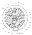
도 1은 본 발명의 바람직한 제1 실시 예에 따른 광전 복합 케이블을 나타내는 도면이다. 상기 광전 복합 케이블(10)은 광섬유 케이블(100), 복수의 전원 케이블(210, 220), 제2 바인더(240), 복수의 개재심(230), 접지 부재(250), 전자파 차폐 부재(260), 제3 바인더(270), 제2 립 코드들(285) 및 제2 피복(280)을 포함한다.1 is a view showing a photoelectric composite cable according to a first embodiment of the present invention. The
상기 광섬유 케이블(100)은 상기 광전 복합 케이블(10)의 중심부에 위치하고, 중심 인장 부재(120), 복수의 튜브(130), 제1 바인더(150), 제1 립 코드(160) 및 제1 피복(110)을 포함한다.The
상기 중심 인장 부재(120)는 상기 광섬유 케이블(10)의 중심부에 배치되며, 상기 광섬유 케이블(10)에 항장력을 제공한다. 상기 중심 인장 부재(120)는 높은 압축 하중 및 인장 하중에 견딜 수 있으며, 난연성(flame retardancy)을 가질 수 있다. 상기 중심 인장 부재(120)는 스틸과 같은 도전성 또는 FRP와 같은 비도전성 재질의 코어만으로 구성되거나, 상기 코어와 상기 코어의 외주면에 적층된 코팅층으로 구성될 수 있다. 상기 코팅층은 비도전성 재질로 이루어지며, 예를 들어 PE, PVC 등과 같은 플라스틱 재질로 이루어질 수 있다.The
상기 복수의 튜브(130)는 상기 중심 인장 부재(120)의 둘레에 배치되며, 그 배치 방식은 직선형 방식, 나선형 방식, S-Z 방식 등일 수 있다. 바람직하게는, 상기 복수의 튜브(130)는 상기 중심 인장 부재(120)를 감싸도록 상기 중심 인장 부재(120)의 외주에 직접적으로(즉, 접촉하여) 감겨 있는 것이 바람직하다. 또한, 이러한 S-Z 방식은 하인리히 아. 크라프트(Heinrich A. Kraft)에 의해 발명되어 특허 허여된 미국특허번호 제4,828,352호(S-Z STRANDED OPTICAL CABLE)에 상세히 개시되었기 때문에 S-Z 방식에 대한 설명은 생략하기로 한다.The plurality of
상기 튜브(130)는 그 중심에 홀(135)을 구비한 중공 실린더 형상을 가지며, 상기 튜브(130)의 홀(135)에는 복수의 착색 광섬유(140)가 실장된다. 상기 튜브(130)는 비도전성 플라스틱 재질로 이루어질 수 있다. 예를 들어, 상기 튜브(130)는 폴리염화비닐(polyvinyl chloride, PVC), 폴리부틸렌테레프탈레이트(polybutylene terephthalate: PBT), 폴리프로필렌(polypropylene: PP), 폴리에틸렌(polyethylene: PE) 또는 폴리우레탄(polyurethane: PU)의 재질로 이루어질 수 있다. 또는, 상기 튜브(130)는 난연 기능을 갖는 LSZH(low smoke zero halogen) 재질로 이루어질 수 있다. 상기 착색 광섬유(140)는 0.9mm 이하의 직경(예를 들어, 0.6mm)을 갖는 것이 바람직하다.The
상기 튜브(130)의 홀(135)에는 흡수성 파우더(powder), 흡수성 얀(water swellable yarn), 흡수성 젤리(jelly) 등과 같은 방수성 또는 흡수성 부재가 충진될 수 있으며, 상기 흡수성 부재는 상기 튜브(130)의 내부로 침입한 수분을 흡수한다.The
또는, 상기 튜브(130)의 홀(135)에 흡수성 부재 대신에 보강 부재가 충진될 수 있다. 상기 보강 부재는 아라미드 얀(aramid yarn), 유리 얀(glass yarn) 등과 같은 보강 얀일 수 있다. 또한, 상기 각 보강 얀을 흡수성 파우더(super absorbent powder)로 코팅한 것, 수분 흡수성 얀(water swellable yarn) 및 아라미드 얀의 조합 등을 상기 보강 부재로서 사용할 수 있다.Alternatively, the reinforcing member may be filled in the
본 실시 예에서, 상기 튜브(130) 내에 식별을 용이하게 하기 위해 착색 광섬유(140)가 실장되는 것으로 예시하고 있으나, 상기 튜브(130) 내에는 광신호의 전송 매체가 되는 임의의 형태의 광전송 매체가 실장될 수 있다. 이러한 광전송 매체들의 예로는, 코어 및 클래드만으로 구성되거나 그 외측에 수지층을 더 구비한 통상적인 광섬유, 타이트 버퍼 광섬유, 리본 광섬유(ribbon optical fiber) 등을 들 수 있다. 즉, 상기 광전송 매체는 고굴절률의 코어(core) 및 저굴절률의 클래드(clad)로 이루어진 베어 광섬유(bare optical fiber), 베어 광섬유를 수지(resin)로 코팅한 것(이러한 타입을 통상적으로 광섬유라고 칭함), 광섬유를 플라스틱(plastic)으로 압출 코팅한 것(이를 버퍼 광섬유라고 칭함), 복수의 광섬유들을 수지로 코팅하여 일체로 형성한 것(이를 리본 광섬유라고 칭함) 등일 수 있다. 상기 타이트 버퍼 광섬유는 타이트 코팅된 광섬유라고도 칭하며, 광신호의 전송 매체가 되며 상대적으로 높은 굴절률을 갖는 코어, 상기 광신호를 상기 코어 내에 가두어두는 기능을 하며 상대적으로 낮은 굴절률을 갖는 클래드 및 상기 코어 및 클래드로 구성된 광섬유를 보호하기 위한 타이트 코팅층을 포함한다. 상기 타이트 코팅층의 재질로는 폴리염화비닐, 하이트렐(hytrel), 나일론(nylon), 폴리에틸렌, 폴리에스테르, 폴리올레핀(polyolefin) 등과 같은 고분자 화합물을 사용할 수 있다.In this embodiment, the colored
상기 제1 바인더(150)는 상기 튜브들(130)을 직접 감싸도록 이들의 둘레에 배치된다. 상기 제1 바인더는 상기 중심 인장 부재(120)의 둘레에 상기 튜브들(130)을 고정하는 기능을 한다. 상기 제1 바인더(150)로는 통상적인 플라스틱 재질(예를 들어, 폴리에스테르)의 테이프, 그 내부로 수분이 침투하는 것을 방지하는 방수성 테이프 등을 사용할 수 있다.The
상기 제1 피복(110)은 상기 제1 바인더(150)를 둘러싸며 상기 광섬유 케이블(100)의 최외곽에 배치된다. 바람직하게는, 상기 제1 피복(110)은 상기 제1 바인더(150)를 감싸도록 상기 제1 바인더(150)의 외주에 직접적으로(즉, 접촉하여) 적층되는 것이 바람직하다. 상기 제1 피복(110)은 상기 광섬유 케이블(100)의 내부를 그 외부로부터 보호하는 기능을 한다. 상기 제1 피복(110)은 상기 바인더(150)의 외주 상에 직접 압출 형성되고, 상기 제1 피복(110)은 플라스틱 재질로 이루어질 수 있으며, 예를 들어 폴리염화비닐(PVC), 폴리에틸렌(PE), 폴리올레핀(polyolefin), 에틸렌 아세트산 비닐 공중합체(EVA), 폴리염화비닐 등으로 이루어질 수 있다. 또한, 상기 제1 피복(110)은 충분한 난연 특성을 보장하기 위해 산소 지수(oxygen index)가 28% 이상인 것이 바람직하다. 산소 지수는 가연성 고체가 발화할 수 있는 한계산소농도의 무차원 값으로서, 한계산소지수(limit oxygen index: LOI)라고도 한다. 상기 제1 피복(110)은 산소 지수를 증가시키기 위해 할로겐 화합물(halogen compound), 수산화 알루미늄 또는 수산화 마그네슘을 함유할 수 있다. 또는, 상기 제1 피복(110)은 난연 기능을 갖는 LSZH(low smoke zero halogen) 재질로 이루어질 수 있다.The
상기 제1 피복(110) 내의 빈 공간(115)에는 방수 얀과 같은 흡수성 부재 또는 아라미드 얀과 같은 보강 부재가 충진될 수 있다.The
상기 제1 립 코드(160)는 상기 제1 바인더(150) 및 제1 피복(110)의 사이에 위치하고, 상기 제1 피복(110)의 탈피를 용이하게 하기 위하여 상기 제1 피복(110)의 내주면에 인접하게 배치된다.The
상기 복수의 전원 케이블(210, 220)은 상기 광섬유 케이블(100)의 둘레에 배치되며, 그 배치 방식은 직선형 방식, 나선형 방식, S-Z 방식 등일 수 있다. 바람직하게는, 상기 복수의 전원 케이블(210, 220)은 상기 광섬유 케이블(100)을 감싸도록 상기 광섬유 케이블(100)의 외주에 직접적으로(즉, 접촉하여) 감겨 있는 것이 바람직하다. 상기 복수의 전원 케이블(210, 220)은 전기 신호의 전송 매체 또는 접지선이 되는 복수의 도선들(conducting wire)(214, 224)과, 상기 도선들(214, 224)을 외부와 절연하도록 상기 도선들(214, 224)을 감싸도록 이들의 외주에 직접적으로(즉, 접촉하여) 적층된 피복(212, 222)을 포함한다. 상기 도선들(214, 224)로는 통상의 구리선을 사용할 수 있다. 상기 피복(212, 222)은 상기 도선들(214, 224)의 외주 상에 직접 압출 형성되고, 상기 피복(212, 222)은 플라스틱 재질로 이루어질 수 있으며, 예를 들어 PE, 폴리올레핀(polyolefin), 에틸렌 아세트산 비닐 공중합체(ethylene vinylacetate copolymer: EVA), PVC, 폴리염화비닐(polyvinyl chloride) 등의 재질로 이루어질 수 있다. 또는, 상기 피복(234)은 난연 기능을 갖는 XLPO(cross-linked polyolefin), 난연 폴리에틸렌 등의 재질로 이루어지거나, LSZH(low smoke zero halogen) 등의 특성을 가질 수 있다. 예를 들어, 상기 전원 케이블(210, 220)은 나선형으로 꼬아진 7개(또는 19개)의 구리선들을 구비할 수 있다.The plurality of
상기 복수의 전원 케이블(210, 220)은 내장 도선들의 전체 직경에 따라 여러 종류로 구분될 수 있다. 본 실시 예에서, 상기 복수의 전원 케이블(210, 220)은 내장 도선들의 전체 직경이 상대적으로 큰 2개의 제1 전원 케이블들(210)과, 내장 도선들의 전체 직경이 상대적으로 작은 6개의 제2 전원 케이블들(220)로 구성된다. 예를 들어, 상기 각 도선은 구리 재질로 이루어질 수 있으며, 또한 1mm2의 단면적을 가질 수 있다.The plurality of
상기 각 전원 케이블(210, 220)은 내장 도선들의 전체 직경, 개별 도선의 직경 또는 수 등을 나타내기 위하여 특정 색상으로 전체 또는 일부 착색되거나, 그 외주면에 노출된 컬러 스트립(216, 226)을 구비할 수 있다.Each of the
상기 제2 바인더(240)는 상기 전원 케이블들(210, 220)을 직접 감싸도록 이들의 둘레에 배치된다. 상기 제2 바인더(240)는 상기 광섬유 케이블(100)의 둘레에 상기 전원 케이블들(210, 220)을 고정하는 기능을 한다. 상기 제2 바인더(240)로는 통상적인 플라스틱 재질(예를 들어, 폴리에스테르)의 테이프, 그 내부로 수분이 침투하는 것을 방지하는 방수성 테이프 등을 사용할 수 있다.The
상기 복수의 개재심(230)은 각각 인접한 두 전원 케이블들(210, 220)의 사이에 형성된 외측 골에 배치됨으로써, 상기 광전 복합 케이블(10)이 원형을 유지할 수 있도록 한다. 예를 들어, 인접한 2개의 제1 전원 케이블들(210)의 사이에는 외측 골(상기 광전 복합 케이블(10)의 외주와 가까운)과 내측 골(상기 광전 복합 케이블(10)의 중심과 가까운)이 형성되며, 하나의 개재심(230)이 상기 제1 전원 케이블들(210)의 사이의 외측 골에 배치된다. 상기 개재심(230)은 하나 이상의 얀으로 구성될 수도 있으며, 상기 개재심(230)의 재질로는 난연 또는 비난연 폴리프로필렌 등의 플라스틱을 사용할 수 있다.The plurality of intervening
상기 전자파 차폐 부재(260)는 상기 제2 바인더(240)의 둘레에 배치되고, 전자파를 차단하는 기능을 한다. 즉, 상기 전자파 차폐 부재(260)는 상기 제2 바인더(240)의 외주를 완전히 감싸며, 그 표면에 입사되는 전자파가 상기 전자파 차폐 부재(260)를 투과하여 그 내부(또는 외부)로 침투하는 것(또는 누설되는 것)을 방지한다. 상기 전자파 차폐 부재(260)에 의해 차단되어 그 표면에 흐르는 전자파는 상기 접지 부재(250)를 통해 외부 접지로 전달된다.The
상기 전자파 차폐 부재(260)로는 알루미늄 마일라 테이프(aluminum mylar tape)를 사용할 수 있다. 본 실시 예에서, 상기 제2 바인더(240) 및 상기 전자파 차폐 부재(260)를 함께 사용하는 것을 예시하고 있으나, 상기 제2 바인더(240)를 제거하고, 상기 전자파 차폐 부재(260)를 상기 전원 케이블들(210, 220)의 둘레에 직접 나선형으로 감아서, 상기 전자파 차폐 부재(260)가 상기 제2 바인더(240)의 기능을 동시에 수행하도록 구현할 수도 있다.An aluminum mylar tape may be used as the
상기 접지 부재(250)는 상기 전자파 차폐 부재(260)와 접촉하도록 상기 제2 바인더(240) 및 상기 전자파 차폐 부재(260)의 사이에 배치된다. 상기 접지 부재(250)는 복수의 도선들을 포함한다. 상기 도선들로는 통상의 구리선을 사용할 수 있다. 예를 들어, 상기 접지 부재(250)는 각각 1mm2의 단면적을 갖는 7개 또는 19개의 구리선들이 나선형으로 꼬아진 드레인 와이어(drain wire)로 구성될 수 있다.The
상기 제3 바인더(270)는 상기 전자파 차폐 부재(260)를 직접 감싸도록 그 둘레에 배치된다. 상기 제3 바인더(270)는 상기 제2 바인더(240)의 둘레에 상기 전자파 차폐 부재(260)를 고정하는 기능을 한다. 상기 제3 바인더(270)로는 통상적인 플라스틱 재질(예를 들어, 폴리에스테르)의 테이프, 그 내부로 수분이 침투하는 것을 방지하는 방수성 테이프 등을 사용할 수 있다.The
상기 제2 피복(280)은 상기 제3 바인더(270)를 둘러싸며 상기 광전 복합 케이블(10)의 최외곽에 배치된다. 바람직하게는, 상기 제2 피복(280)은 상기 제3 바인더(270)를 감싸도록 상기 제3 바인더(280)의 외주에 직접적으로(즉, 접촉하여) 적층되는 것이 바람직하다. 상기 제2 피복(280)은 상기 광전 복합 케이블(10)의 내부를 그 외부로부터 보호하는 기능을 한다. 상기 제2 피복(280)은 상기 제3 바인더(270)의 외주 상에 직접 압출 형성되고, 상기 제2 피복(280)은 플라스틱 재질로 이루어질 수 있으며, 예를 들어 폴리염화비닐(PVC), 폴리에틸렌(PE), 폴리올레핀(polyolefin), 에틸렌 아세트산 비닐 공중합체(EVA), 폴리염화비닐 등으로 이루어질 수 있다. 또한, 상기 제2 피복(280)은 충분한 난연 특성을 보장하기 위해 산소 지수(oxygen index)가 28% 이상인 것이 바람직하다. 상기 제2 피복(280)은 산소 지수를 증가시키기 위해 할로겐 화합물(halogen compound), 수산화 알루미늄 또는 수산화 마그네슘을 함유할 수 있다. 또는, 상기 제2 피복(280)은 난연 기능을 갖는 LSZH(low smoke zero halogen) 재질로 이루어질 수 있다.The
상기 제2 피복(280)(또는 제2 바인더(240)) 내의 빈 공간(232)에는 방수 얀과 같은 흡수성 부재 또는 아라미드 얀과 같은 보강 부재가 충진될 수 있다.The
상기 제2 립 코드들(285)은 상기 제3 바인더(270) 및 제2 피복(280)의 사이에 위치하고, 상기 제2 피복(280)의 탈피를 용이하게 하기 위하여 상기 제2 피복(280)의 내주면에 인접하게 배치된다.The
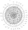
도 2는 본 발명의 바람직한 제2 실시 예에 따른 광전 복합 케이블을 나타내는 도면이다. 상기 광전 복합 케이블(10')은 도 1에 도시된 광전 복합 케이블(10)과 유사한 구성을 가지며, 단지 상기 광전 복합 케이블(10')의 중심부에 광섬유 케이블(100)을 둘러싸는 미니 덕트(300)를 더 포함한다는 점에서만 차이가 있다. 따라서, 동일한 구성 요소에 대해서는 동일한 도면 부호를 사용하고, 중복되는 설명은 생략하기로 한다.2 is a view showing a photoelectric composite cable according to a second embodiment of the present invention. The photoelectric composite cable 10 'has a configuration similar to that of the photoelectric
상기 미니 덕트(300)는 상기 광전 복합 케이블(10')의 중심부에 위치하고, 상기 미니 덕트(300)는 그 중심에 홀(310)을 구비한 중공 실린더 형상을 가지며, 상기 미니 덕트(300)의 홀(310)에는 상기 광섬유 케이블(100)이 실장된다. 상기 미니 덕트(300)는 비도전성 플라스틱 재질로 이루어질 수 있다. 예를 들어, 상기 튜브(130)는 폴리염화비닐(polyvinyl chloride, PVC), 폴리부틸렌테레프탈레이트(polybutylene terephthalate: PBT), 폴리프로필렌(polypropylene: PP), 폴리에틸렌(polyethylene: PE) 또는 폴리우레탄(polyurethane: PU)의 재질로 이루어질 수 있다. 또는, 상기 미니 덕트(300)는 LSZH 재질로 이루어질 수 있다.The
상기 미니 덕트(300)의 홀(310)의 직경은 상기 광섬유 케이블(100)의 외경보다 크며, 상기 미니 덕트(300)의 홀(310)이 여분의 공간을 가짐으로써, 추후 필요에 따라 상기 미니 덕트(300) 내에 다른 광섬유 케이블을 더 실장할 수 있다. 예를 들어, 상기 광섬유 케이블(100)이 차지하는 단면적은 상기 미니 덕트(300)의 홀(310)이 차지하는 단면적의 85% 이하에 해당하는 것이 바람직하다.The diameter of the
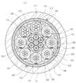
도 3은 본 발명의 바람직한 제3 실시 예에 따른 광전 복합 케이블을 나타내는 도면이다. 상기 광전 복합 케이블(10")은 도 1에 도시된 광전 복합 케이블(10)과 유사한 구성을 가지며, 단지 도 1에 도시된 광섬유 케이블(100)에서 제1 립 코드(160) 및 제1 피복(110)을 제거하였다는 점에서만 차이가 있다. 따라서, 동일한 구성 요소에 대해서는 동일한 도면 부호를 사용하고, 중복되는 설명은 생략하기로 한다.3 is a view showing a photoelectric composite cable according to a third embodiment of the present invention. The optoelectronic
도시된 바와 같이, 광섬유 케이블(100')은 상기 광전 복합 케이블(10")의 중심부에 위치하고, 중심 인장 부재(120), 복수의 튜브(130) 및 제1 바인더(150)를 포함하고, 피복 및 립 코드를 포함하지 않는다.As shown, the
복수의 전원 케이블(210, 220)은 상기 광섬유 케이블(100')의 둘레에 배치되며, 그 배치 방식은 직선형 방식, 나선형 방식, S-Z 방식 등일 수 있다. 바람직하게는, 상기 복수의 전원 케이블(210, 220)은 상기 광섬유 케이블(100')을 감싸도록 상기 제1 바인더(150)의 외주에 직접적으로(즉, 접촉하여) 감겨 있는 것이 바람직하다.The plurality of
10: 광전 복합 케이블, 100: 광섬유 케이블, 210, 220: 전원 케이블, 240: 제2 바인더, 230: 개재심, 250: 접지 부재, 260: 전자파 차폐 부재, 270: 제3 바인더, 280: 제2 피복Reference Signs List 10: photoelectric composite cable, 100: optical fiber cable, 210, 220: power cable, 240: second binder, 230: interposition core, 250: ground member, 260: electromagnetic wave shield member, 270: third binder, 280: second covering
Claims (8)
Translated fromKorean상기 광전 복합 케이블의 중심부에 위치하는 미니 덕트와;
상기 미니 덕트의 내부 공간에 실장되고, 각각 복수의 광섬유를 그 내부 공간에 실장하는 복수의 튜브와, 상기 복수의 튜브의 둘레에 위치하는 바인더를 포함하는 광섬유 케이블과;
상기 광섬유 케이블 및 상기 미니 덕트의 둘레에 위치하고, 각각 복수의 도선을 구비한 복수의 전원 케이블과;
상기 복수의 전원 케이블의 둘레에 위치하는 피복을 포함함을 특징으로 하는 광전 복합 케이블.In the photoelectric composite cable for transmitting an optical signal and an electrical signal at the same time,
A mini duct positioned at the center of the photoelectric composite cable;
An optical fiber cable mounted in an internal space of the mini duct, each optical fiber including a plurality of tubes for mounting a plurality of optical fibers in the inner space, and a binder positioned around the plurality of tubes;
A plurality of power cables positioned around the optical fiber cable and the mini duct, each having a plurality of conductive wires;
And a sheath positioned around the plurality of power cables.
상기 바인더의 둘레에 위치하며, 상기 광섬유 케이블의 최외곽에 위치하는 피복을 더 포함함을 특징으로 하는 광전 복합 케이블.The method of claim 1, wherein the optical fiber cable,
And a sheath disposed around the binder and positioned at an outermost portion of the optical fiber cable.
상기 광전 복합 케이블이 원형을 유지할 수 있도록, 상기 복수의 전원 케이블과 상기 피복의 사이에 배치된 복수의 개재심을 더 포함함을 특징으로 하는 광전 복합 케이블.The method of claim 1,
And a plurality of intervening cores disposed between the plurality of power cables and the sheathing so that the photoelectric composite cable can maintain a circular shape.
전자파 차폐를 위하여, 상기 복수의 전원 케이블과 상기 피복의 사이에 배치된 전자파 차폐 부재를 더 포함함을 특징으로 하는 광전 복합 케이블.The method of claim 1,
And an electromagnetic shielding member disposed between the plurality of power cables and the sheathing for electromagnetic shielding.
상기 전자파 차폐 부재와 접촉하도록, 상기 복수의 전원 케이블과 상기 피복의 사이에 배치된 접지 부재를 더 포함함을 특징으로 하는 광전 복합 케이블.The method of claim 5,
And a grounding member disposed between the plurality of power cables and the sheathing so as to contact the electromagnetic shielding member.
상기 적어도 하나의 도선과;
상기 도선의 둘레에 배치된 비도전성 피복을 포함함을 특징으로 하는 광전 복합 케이블.The method of claim 1, wherein the power cable,
The at least one conductive wire;
And a non-conductive sheath disposed around the conductor.
Priority Applications (6)
| Application Number | Priority Date | Filing Date | Title |
|---|---|---|---|
| KR1020110041847AKR101261320B1 (en) | 2011-05-03 | 2011-05-03 | Optical electrical hybrid cable |
| MX2012004958AMX2012004958A (en) | 2011-05-03 | 2012-04-27 | Optical electrical hybrid cable. |
| CN201210202443.XACN102768883B (en) | 2011-05-03 | 2012-04-28 | Optical electrical hybrid cable |
| CA2775698ACA2775698C (en) | 2011-05-03 | 2012-04-30 | Optical electrical hybrid cable |
| US13/462,054US8792760B2 (en) | 2011-05-03 | 2012-05-02 | Optical electrical hybrid cable |
| EP12166405.6AEP2520962B8 (en) | 2011-05-03 | 2012-05-02 | Optical electrical hybrid cable |
Applications Claiming Priority (1)
| Application Number | Priority Date | Filing Date | Title |
|---|---|---|---|
| KR1020110041847AKR101261320B1 (en) | 2011-05-03 | 2011-05-03 | Optical electrical hybrid cable |
Publications (2)
| Publication Number | Publication Date |
|---|---|
| KR20120124139A KR20120124139A (en) | 2012-11-13 |
| KR101261320B1true KR101261320B1 (en) | 2013-05-07 |
Family
ID=46087484
Family Applications (1)
| Application Number | Title | Priority Date | Filing Date |
|---|---|---|---|
| KR1020110041847AExpired - Fee RelatedKR101261320B1 (en) | 2011-05-03 | 2011-05-03 | Optical electrical hybrid cable |
Country Status (6)
| Country | Link |
|---|---|
| US (1) | US8792760B2 (en) |
| EP (1) | EP2520962B8 (en) |
| KR (1) | KR101261320B1 (en) |
| CN (1) | CN102768883B (en) |
| CA (1) | CA2775698C (en) |
| MX (1) | MX2012004958A (en) |
Cited By (2)
| Publication number | Priority date | Publication date | Assignee | Title |
|---|---|---|---|---|
| WO2015126157A1 (en)* | 2014-02-18 | 2015-08-27 | 김문성 | Integrated cable for data communication |
| US12165789B2 (en) | 2020-01-08 | 2024-12-10 | Samsung Electronics Co., Ltd. | Flexible flat cable and manufacturing method therefor |
Families Citing this family (217)
| Publication number | Priority date | Publication date | Assignee | Title |
|---|---|---|---|---|
| US8532490B2 (en) | 2009-03-05 | 2013-09-10 | Adc Telecommunications, Inc. | Methods, systems and devices for integrating wireless technology into a fiber optic network |
| US8837940B2 (en) | 2010-04-14 | 2014-09-16 | Adc Telecommunications, Inc. | Methods and systems for distributing fiber optic telecommunication services to local areas and for supporting distributed antenna systems |
| US9078287B2 (en) | 2010-04-14 | 2015-07-07 | Adc Telecommunications, Inc. | Fiber to the antenna |
| US10087717B2 (en) | 2011-10-17 | 2018-10-02 | Schlumberger Technology Corporation | Dual use cable with fiber optics for use in wellbore operations |
| US8909012B2 (en) | 2012-04-27 | 2014-12-09 | Corning Cable Systems Llc | Hybrid cable including fiber-optic and electrical-conductor stranded elements |
| JP2015517679A (en) | 2012-05-02 | 2015-06-22 | エーエフエル・テレコミュニケーションズ・エルエルシー | Circular and small-diameter optical cable with ribbon-type optical fiber structure |
| WO2013188973A1 (en)* | 2012-06-18 | 2013-12-27 | Universite Laval | Optogenetic probe |
| MX357738B (en) | 2012-06-28 | 2018-07-23 | Schlumberger Technology Bv | OPTO-ELECTRIC HIGH POWER CABLE WITH MULTIPLE ENERGY AND TELEMETRY ROUTES. |
| US9188756B2 (en) | 2012-08-06 | 2015-11-17 | Corning Cable Systems Llc | Hybrid cable with fiber-optic and conductor elements |
| US8886000B2 (en) | 2012-09-05 | 2014-11-11 | Corning Cable Systems Llc | Hybrid fiber-optic cable |
| JP5273284B1 (en)* | 2012-09-20 | 2013-08-28 | 日立電線株式会社 | Photoelectric composite cable |
| US8620124B1 (en) | 2012-09-26 | 2013-12-31 | Corning Cable Systems Llc | Binder film for a fiber optic cable |
| US11287589B2 (en) | 2012-09-26 | 2022-03-29 | Corning Optical Communications LLC | Binder film for a fiber optic cable |
| US9091830B2 (en) | 2012-09-26 | 2015-07-28 | Corning Cable Systems Llc | Binder film for a fiber optic cable |
| WO2014081784A1 (en)* | 2012-11-26 | 2014-05-30 | Ii-Vi Incorporated | Heated ribbon erbium doped fiber |
| US10009065B2 (en) | 2012-12-05 | 2018-06-26 | At&T Intellectual Property I, L.P. | Backhaul link for distributed antenna system |
| US9113347B2 (en) | 2012-12-05 | 2015-08-18 | At&T Intellectual Property I, Lp | Backhaul link for distributed antenna system |
| US9557505B2 (en) | 2013-03-18 | 2017-01-31 | Commscope Technologies Llc | Power and optical fiber interface |
| CN105247805B (en) | 2013-03-18 | 2017-12-08 | 阿德斯电信公司 | Framework for wireless network |
| JP6015542B2 (en)* | 2013-04-25 | 2016-10-26 | 日立金属株式会社 | Photoelectric composite cable |
| CN105247627B (en) | 2013-05-14 | 2018-08-10 | 阿德斯电信公司 | Power/Fiber Optic Hybrid Cable |
| US9999038B2 (en) | 2013-05-31 | 2018-06-12 | At&T Intellectual Property I, L.P. | Remote distributed antenna system |
| US9525524B2 (en) | 2013-05-31 | 2016-12-20 | At&T Intellectual Property I, L.P. | Remote distributed antenna system |
| US9482839B2 (en) | 2013-08-09 | 2016-11-01 | Corning Cable Systems Llc | Optical fiber cable with anti-split feature |
| WO2015026067A1 (en)* | 2013-08-22 | 2015-02-26 | 엘에스전선 주식회사 | Hdmi cable comprising optical fiber unit |
| KR102181050B1 (en)* | 2013-08-22 | 2020-11-20 | 엘에스전선 주식회사 | High-Definition Multimedia Interface Cable having optical fiber unit |
| US9075212B2 (en) | 2013-09-24 | 2015-07-07 | Corning Optical Communications LLC | Stretchable fiber optic cable |
| US8805144B1 (en) | 2013-09-24 | 2014-08-12 | Corning Optical Communications LLC | Stretchable fiber optic cable |
| US8913862B1 (en) | 2013-09-27 | 2014-12-16 | Corning Optical Communications LLC | Optical communication cable |
| US9594226B2 (en) | 2013-10-18 | 2017-03-14 | Corning Optical Communications LLC | Optical fiber cable with reinforcement |
| US8897697B1 (en) | 2013-11-06 | 2014-11-25 | At&T Intellectual Property I, Lp | Millimeter-wave surface-wave communications |
| US9209902B2 (en) | 2013-12-10 | 2015-12-08 | At&T Intellectual Property I, L.P. | Quasi-optical coupler |
| BR212016015387U2 (en)* | 2013-12-30 | 2016-09-27 | Corning Optical Comm Llc | film for a flame retardant fiber optic cable |
| US10175437B2 (en)* | 2014-02-18 | 2019-01-08 | Pgs Geophysical As | Subsea cable having floodable optical fiber conduit |
| US9692101B2 (en) | 2014-08-26 | 2017-06-27 | At&T Intellectual Property I, L.P. | Guided wave couplers for coupling electromagnetic waves between a waveguide surface and a surface of a wire |
| US9768833B2 (en) | 2014-09-15 | 2017-09-19 | At&T Intellectual Property I, L.P. | Method and apparatus for sensing a condition in a transmission medium of electromagnetic waves |
| US10063280B2 (en) | 2014-09-17 | 2018-08-28 | At&T Intellectual Property I, L.P. | Monitoring and mitigating conditions in a communication network |
| US9628854B2 (en) | 2014-09-29 | 2017-04-18 | At&T Intellectual Property I, L.P. | Method and apparatus for distributing content in a communication network |
| US9615269B2 (en) | 2014-10-02 | 2017-04-04 | At&T Intellectual Property I, L.P. | Method and apparatus that provides fault tolerance in a communication network |
| US9685992B2 (en) | 2014-10-03 | 2017-06-20 | At&T Intellectual Property I, L.P. | Circuit panel network and methods thereof |
| US9503189B2 (en) | 2014-10-10 | 2016-11-22 | At&T Intellectual Property I, L.P. | Method and apparatus for arranging communication sessions in a communication system |
| US9762289B2 (en) | 2014-10-14 | 2017-09-12 | At&T Intellectual Property I, L.P. | Method and apparatus for transmitting or receiving signals in a transportation system |
| US9973299B2 (en) | 2014-10-14 | 2018-05-15 | At&T Intellectual Property I, L.P. | Method and apparatus for adjusting a mode of communication in a communication network |
| US9564947B2 (en) | 2014-10-21 | 2017-02-07 | At&T Intellectual Property I, L.P. | Guided-wave transmission device with diversity and methods for use therewith |
| US9769020B2 (en) | 2014-10-21 | 2017-09-19 | At&T Intellectual Property I, L.P. | Method and apparatus for responding to events affecting communications in a communication network |
| US9653770B2 (en) | 2014-10-21 | 2017-05-16 | At&T Intellectual Property I, L.P. | Guided wave coupler, coupling module and methods for use therewith |
| US9520945B2 (en) | 2014-10-21 | 2016-12-13 | At&T Intellectual Property I, L.P. | Apparatus for providing communication services and methods thereof |
| US9577306B2 (en) | 2014-10-21 | 2017-02-21 | At&T Intellectual Property I, L.P. | Guided-wave transmission device and methods for use therewith |
| US9312919B1 (en) | 2014-10-21 | 2016-04-12 | At&T Intellectual Property I, Lp | Transmission device with impairment compensation and methods for use therewith |
| US9627768B2 (en) | 2014-10-21 | 2017-04-18 | At&T Intellectual Property I, L.P. | Guided-wave transmission device with non-fundamental mode propagation and methods for use therewith |
| US9780834B2 (en) | 2014-10-21 | 2017-10-03 | At&T Intellectual Property I, L.P. | Method and apparatus for transmitting electromagnetic waves |
| US10505252B2 (en) | 2014-11-20 | 2019-12-10 | At&T Intellectual Property I, L.P. | Communication system having a coupler for guiding electromagnetic waves through interstitial areas formed by a plurality of stranded uninsulated conductors and method of use |
| US9654173B2 (en) | 2014-11-20 | 2017-05-16 | At&T Intellectual Property I, L.P. | Apparatus for powering a communication device and methods thereof |
| US10411920B2 (en) | 2014-11-20 | 2019-09-10 | At&T Intellectual Property I, L.P. | Methods and apparatus for inducing electromagnetic waves within pathways of a cable |
| US10505250B2 (en) | 2014-11-20 | 2019-12-10 | At&T Intellectual Property I, L.P. | Communication system having a cable with a plurality of stranded uninsulated conductors forming interstitial areas for propagating guided wave modes therein and methods of use |
| US9680670B2 (en) | 2014-11-20 | 2017-06-13 | At&T Intellectual Property I, L.P. | Transmission device with channel equalization and control and methods for use therewith |
| US10340573B2 (en) | 2016-10-26 | 2019-07-02 | At&T Intellectual Property I, L.P. | Launcher with cylindrical coupling device and methods for use therewith |
| US10516555B2 (en) | 2014-11-20 | 2019-12-24 | At&T Intellectual Property I, L.P. | Methods and apparatus for creating interstitial areas in a cable |
| US11025460B2 (en) | 2014-11-20 | 2021-06-01 | At&T Intellectual Property I, L.P. | Methods and apparatus for accessing interstitial areas of a cable |
| US10505249B2 (en) | 2014-11-20 | 2019-12-10 | At&T Intellectual Property I, L.P. | Communication system having a cable with a plurality of stranded uninsulated conductors forming interstitial areas for guiding electromagnetic waves therein and method of use |
| US9461706B1 (en) | 2015-07-31 | 2016-10-04 | At&T Intellectual Property I, Lp | Method and apparatus for exchanging communication signals |
| US9997819B2 (en) | 2015-06-09 | 2018-06-12 | At&T Intellectual Property I, L.P. | Transmission medium and method for facilitating propagation of electromagnetic waves via a core |
| US10505248B2 (en) | 2014-11-20 | 2019-12-10 | At&T Intellectual Property I, L.P. | Communication cable having a plurality of uninsulated conductors forming interstitial areas for propagating electromagnetic waves therein and method of use |
| US9954287B2 (en) | 2014-11-20 | 2018-04-24 | At&T Intellectual Property I, L.P. | Apparatus for converting wireless signals and electromagnetic waves and methods thereof |
| US9742462B2 (en) | 2014-12-04 | 2017-08-22 | At&T Intellectual Property I, L.P. | Transmission medium and communication interfaces and methods for use therewith |
| US10554454B2 (en) | 2014-11-20 | 2020-02-04 | At&T Intellectual Property I, L.P. | Methods and apparatus for inducing electromagnetic waves in a cable |
| US10009067B2 (en) | 2014-12-04 | 2018-06-26 | At&T Intellectual Property I, L.P. | Method and apparatus for configuring a communication interface |
| US9800327B2 (en) | 2014-11-20 | 2017-10-24 | At&T Intellectual Property I, L.P. | Apparatus for controlling operations of a communication device and methods thereof |
| US9544006B2 (en) | 2014-11-20 | 2017-01-10 | At&T Intellectual Property I, L.P. | Transmission device with mode division multiplexing and methods for use therewith |
| US10243784B2 (en) | 2014-11-20 | 2019-03-26 | At&T Intellectual Property I, L.P. | System for generating topology information and methods thereof |
| CN105590671A (en)* | 2014-12-18 | 2016-05-18 | 王笑梅 | Opto-electric hybrid cable comprising coaxial electric units |
| EP3250785B1 (en)* | 2015-01-26 | 2022-09-21 | Services Pétroliers Schlumberger | Electrically conductive fiber optic slickline for coiled tubing operations |
| US10144036B2 (en) | 2015-01-30 | 2018-12-04 | At&T Intellectual Property I, L.P. | Method and apparatus for mitigating interference affecting a propagation of electromagnetic waves guided by a transmission medium |
| US9876570B2 (en) | 2015-02-20 | 2018-01-23 | At&T Intellectual Property I, Lp | Guided-wave transmission device with non-fundamental mode propagation and methods for use therewith |
| BR112017019193A2 (en)* | 2015-03-10 | 2018-04-24 | Corning Optical Communications LLC | ? fiber optic bundle? |
| US9749013B2 (en) | 2015-03-17 | 2017-08-29 | At&T Intellectual Property I, L.P. | Method and apparatus for reducing attenuation of electromagnetic waves guided by a transmission medium |
| US9705561B2 (en) | 2015-04-24 | 2017-07-11 | At&T Intellectual Property I, L.P. | Directional coupling device and methods for use therewith |
| US10224981B2 (en) | 2015-04-24 | 2019-03-05 | At&T Intellectual Property I, Lp | Passive electrical coupling device and methods for use therewith |
| US9793954B2 (en) | 2015-04-28 | 2017-10-17 | At&T Intellectual Property I, L.P. | Magnetic coupling device and methods for use therewith |
| US9948354B2 (en) | 2015-04-28 | 2018-04-17 | At&T Intellectual Property I, L.P. | Magnetic coupling device with reflective plate and methods for use therewith |
| US9490869B1 (en) | 2015-05-14 | 2016-11-08 | At&T Intellectual Property I, L.P. | Transmission medium having multiple cores and methods for use therewith |
| US9748626B2 (en) | 2015-05-14 | 2017-08-29 | At&T Intellectual Property I, L.P. | Plurality of cables having different cross-sectional shapes which are bundled together to form a transmission medium |
| US9871282B2 (en) | 2015-05-14 | 2018-01-16 | At&T Intellectual Property I, L.P. | At least one transmission medium having a dielectric surface that is covered at least in part by a second dielectric |
| US10650940B2 (en) | 2015-05-15 | 2020-05-12 | At&T Intellectual Property I, L.P. | Transmission medium having a conductive material and methods for use therewith |
| US10679767B2 (en) | 2015-05-15 | 2020-06-09 | At&T Intellectual Property I, L.P. | Transmission medium having a conductive material and methods for use therewith |
| US9917341B2 (en) | 2015-05-27 | 2018-03-13 | At&T Intellectual Property I, L.P. | Apparatus and method for launching electromagnetic waves and for modifying radial dimensions of the propagating electromagnetic waves |
| US10812174B2 (en) | 2015-06-03 | 2020-10-20 | At&T Intellectual Property I, L.P. | Client node device and methods for use therewith |
| US10154493B2 (en) | 2015-06-03 | 2018-12-11 | At&T Intellectual Property I, L.P. | Network termination and methods for use therewith |
| US10103801B2 (en) | 2015-06-03 | 2018-10-16 | At&T Intellectual Property I, L.P. | Host node device and methods for use therewith |
| US9866309B2 (en) | 2015-06-03 | 2018-01-09 | At&T Intellectual Property I, Lp | Host node device and methods for use therewith |
| US10348391B2 (en) | 2015-06-03 | 2019-07-09 | At&T Intellectual Property I, L.P. | Client node device with frequency conversion and methods for use therewith |
| US9912381B2 (en) | 2015-06-03 | 2018-03-06 | At&T Intellectual Property I, Lp | Network termination and methods for use therewith |
| US9913139B2 (en) | 2015-06-09 | 2018-03-06 | At&T Intellectual Property I, L.P. | Signal fingerprinting for authentication of communicating devices |
| EP3104203A1 (en)* | 2015-06-09 | 2016-12-14 | Sterlite Technologies Ltd | Easy accessable outdoor optical fiber cable |
| US10142086B2 (en) | 2015-06-11 | 2018-11-27 | At&T Intellectual Property I, L.P. | Repeater and methods for use therewith |
| US9608692B2 (en) | 2015-06-11 | 2017-03-28 | At&T Intellectual Property I, L.P. | Repeater and methods for use therewith |
| US9820146B2 (en) | 2015-06-12 | 2017-11-14 | At&T Intellectual Property I, L.P. | Method and apparatus for authentication and identity management of communicating devices |
| US9667317B2 (en) | 2015-06-15 | 2017-05-30 | At&T Intellectual Property I, L.P. | Method and apparatus for providing security using network traffic adjustments |
| US9509415B1 (en) | 2015-06-25 | 2016-11-29 | At&T Intellectual Property I, L.P. | Methods and apparatus for inducing a fundamental wave mode on a transmission medium |
| US9865911B2 (en) | 2015-06-25 | 2018-01-09 | At&T Intellectual Property I, L.P. | Waveguide system for slot radiating first electromagnetic waves that are combined into a non-fundamental wave mode second electromagnetic wave on a transmission medium |
| US9640850B2 (en) | 2015-06-25 | 2017-05-02 | At&T Intellectual Property I, L.P. | Methods and apparatus for inducing a non-fundamental wave mode on a transmission medium |
| US10170840B2 (en) | 2015-07-14 | 2019-01-01 | At&T Intellectual Property I, L.P. | Apparatus and methods for sending or receiving electromagnetic signals |
| US9628116B2 (en) | 2015-07-14 | 2017-04-18 | At&T Intellectual Property I, L.P. | Apparatus and methods for transmitting wireless signals |
| US9722318B2 (en) | 2015-07-14 | 2017-08-01 | At&T Intellectual Property I, L.P. | Method and apparatus for coupling an antenna to a device |
| US10320586B2 (en) | 2015-07-14 | 2019-06-11 | At&T Intellectual Property I, L.P. | Apparatus and methods for generating non-interfering electromagnetic waves on an insulated transmission medium |
| US9882257B2 (en) | 2015-07-14 | 2018-01-30 | At&T Intellectual Property I, L.P. | Method and apparatus for launching a wave mode that mitigates interference |
| US9836957B2 (en) | 2015-07-14 | 2017-12-05 | At&T Intellectual Property I, L.P. | Method and apparatus for communicating with premises equipment |
| US10341142B2 (en) | 2015-07-14 | 2019-07-02 | At&T Intellectual Property I, L.P. | Apparatus and methods for generating non-interfering electromagnetic waves on an uninsulated conductor |
| US10033108B2 (en) | 2015-07-14 | 2018-07-24 | At&T Intellectual Property I, L.P. | Apparatus and methods for generating an electromagnetic wave having a wave mode that mitigates interference |
| US10205655B2 (en) | 2015-07-14 | 2019-02-12 | At&T Intellectual Property I, L.P. | Apparatus and methods for communicating utilizing an antenna array and multiple communication paths |
| US9853342B2 (en) | 2015-07-14 | 2017-12-26 | At&T Intellectual Property I, L.P. | Dielectric transmission medium connector and methods for use therewith |
| US10148016B2 (en) | 2015-07-14 | 2018-12-04 | At&T Intellectual Property I, L.P. | Apparatus and methods for communicating utilizing an antenna array |
| US9847566B2 (en) | 2015-07-14 | 2017-12-19 | At&T Intellectual Property I, L.P. | Method and apparatus for adjusting a field of a signal to mitigate interference |
| US10044409B2 (en)* | 2015-07-14 | 2018-08-07 | At&T Intellectual Property I, L.P. | Transmission medium and methods for use therewith |
| US10033107B2 (en) | 2015-07-14 | 2018-07-24 | At&T Intellectual Property I, L.P. | Method and apparatus for coupling an antenna to a device |
| US9793951B2 (en) | 2015-07-15 | 2017-10-17 | At&T Intellectual Property I, L.P. | Method and apparatus for launching a wave mode that mitigates interference |
| US10090606B2 (en) | 2015-07-15 | 2018-10-02 | At&T Intellectual Property I, L.P. | Antenna system with dielectric array and methods for use therewith |
| US9608740B2 (en) | 2015-07-15 | 2017-03-28 | At&T Intellectual Property I, L.P. | Method and apparatus for launching a wave mode that mitigates interference |
| US9912027B2 (en) | 2015-07-23 | 2018-03-06 | At&T Intellectual Property I, L.P. | Method and apparatus for exchanging communication signals |
| US10784670B2 (en) | 2015-07-23 | 2020-09-22 | At&T Intellectual Property I, L.P. | Antenna support for aligning an antenna |
| US9749053B2 (en) | 2015-07-23 | 2017-08-29 | At&T Intellectual Property I, L.P. | Node device, repeater and methods for use therewith |
| US9871283B2 (en) | 2015-07-23 | 2018-01-16 | At&T Intellectual Property I, Lp | Transmission medium having a dielectric core comprised of plural members connected by a ball and socket configuration |
| US9948333B2 (en) | 2015-07-23 | 2018-04-17 | At&T Intellectual Property I, L.P. | Method and apparatus for wireless communications to mitigate interference |
| US10020587B2 (en) | 2015-07-31 | 2018-07-10 | At&T Intellectual Property I, L.P. | Radial antenna and methods for use therewith |
| US9735833B2 (en) | 2015-07-31 | 2017-08-15 | At&T Intellectual Property I, L.P. | Method and apparatus for communications management in a neighborhood network |
| US9967173B2 (en) | 2015-07-31 | 2018-05-08 | At&T Intellectual Property I, L.P. | Method and apparatus for authentication and identity management of communicating devices |
| MX2018002005A (en) | 2015-08-18 | 2018-06-19 | Corning Optical Communications LLC | MAKE OPTICAL FIBER. |
| US9904535B2 (en) | 2015-09-14 | 2018-02-27 | At&T Intellectual Property I, L.P. | Method and apparatus for distributing software |
| US10136434B2 (en) | 2015-09-16 | 2018-11-20 | At&T Intellectual Property I, L.P. | Method and apparatus for use with a radio distributed antenna system having an ultra-wideband control channel |
| US10009063B2 (en) | 2015-09-16 | 2018-06-26 | At&T Intellectual Property I, L.P. | Method and apparatus for use with a radio distributed antenna system having an out-of-band reference signal |
| US9705571B2 (en) | 2015-09-16 | 2017-07-11 | At&T Intellectual Property I, L.P. | Method and apparatus for use with a radio distributed antenna system |
| US10051629B2 (en) | 2015-09-16 | 2018-08-14 | At&T Intellectual Property I, L.P. | Method and apparatus for use with a radio distributed antenna system having an in-band reference signal |
| US10079661B2 (en) | 2015-09-16 | 2018-09-18 | At&T Intellectual Property I, L.P. | Method and apparatus for use with a radio distributed antenna system having a clock reference |
| US10009901B2 (en) | 2015-09-16 | 2018-06-26 | At&T Intellectual Property I, L.P. | Method, apparatus, and computer-readable storage medium for managing utilization of wireless resources between base stations |
| US9769128B2 (en) | 2015-09-28 | 2017-09-19 | At&T Intellectual Property I, L.P. | Method and apparatus for encryption of communications over a network |
| US9729197B2 (en) | 2015-10-01 | 2017-08-08 | At&T Intellectual Property I, L.P. | Method and apparatus for communicating network management traffic over a network |
| US9882277B2 (en) | 2015-10-02 | 2018-01-30 | At&T Intellectual Property I, Lp | Communication device and antenna assembly with actuated gimbal mount |
| US10074890B2 (en) | 2015-10-02 | 2018-09-11 | At&T Intellectual Property I, L.P. | Communication device and antenna with integrated light assembly |
| US9876264B2 (en) | 2015-10-02 | 2018-01-23 | At&T Intellectual Property I, Lp | Communication system, guided wave switch and methods for use therewith |
| US10665942B2 (en) | 2015-10-16 | 2020-05-26 | At&T Intellectual Property I, L.P. | Method and apparatus for adjusting wireless communications |
| US10051483B2 (en) | 2015-10-16 | 2018-08-14 | At&T Intellectual Property I, L.P. | Method and apparatus for directing wireless signals |
| US10355367B2 (en) | 2015-10-16 | 2019-07-16 | At&T Intellectual Property I, L.P. | Antenna structure for exchanging wireless signals |
| US10049789B2 (en) | 2016-06-09 | 2018-08-14 | Schlumberger Technology Corporation | Compression and stretch resistant components and cables for oilfield applications |
| US9912419B1 (en) | 2016-08-24 | 2018-03-06 | At&T Intellectual Property I, L.P. | Method and apparatus for managing a fault in a distributed antenna system |
| US9860075B1 (en) | 2016-08-26 | 2018-01-02 | At&T Intellectual Property I, L.P. | Method and communication node for broadband distribution |
| US10291311B2 (en) | 2016-09-09 | 2019-05-14 | At&T Intellectual Property I, L.P. | Method and apparatus for mitigating a fault in a distributed antenna system |
| US11032819B2 (en) | 2016-09-15 | 2021-06-08 | At&T Intellectual Property I, L.P. | Method and apparatus for use with a radio distributed antenna system having a control channel reference signal |
| BR102016021858A2 (en)* | 2016-09-22 | 2018-04-10 | Furukawa Electric Latam S.A. | MESSENGER CABLE FOR ENERGY DISTRIBUTION LINES AND PROCESSING MESSENGER CABLE FOR POWER DISTRIBUTION LINES |
| US10135146B2 (en) | 2016-10-18 | 2018-11-20 | At&T Intellectual Property I, L.P. | Apparatus and methods for launching guided waves via circuits |
| US10135147B2 (en) | 2016-10-18 | 2018-11-20 | At&T Intellectual Property I, L.P. | Apparatus and methods for launching guided waves via an antenna |
| US10340600B2 (en) | 2016-10-18 | 2019-07-02 | At&T Intellectual Property I, L.P. | Apparatus and methods for launching guided waves via plural waveguide systems |
| US10374316B2 (en) | 2016-10-21 | 2019-08-06 | At&T Intellectual Property I, L.P. | System and dielectric antenna with non-uniform dielectric |
| US10811767B2 (en) | 2016-10-21 | 2020-10-20 | At&T Intellectual Property I, L.P. | System and dielectric antenna with convex dielectric radome |
| US9876605B1 (en) | 2016-10-21 | 2018-01-23 | At&T Intellectual Property I, L.P. | Launcher and coupling system to support desired guided wave mode |
| US9991580B2 (en) | 2016-10-21 | 2018-06-05 | At&T Intellectual Property I, L.P. | Launcher and coupling system for guided wave mode cancellation |
| US10312567B2 (en) | 2016-10-26 | 2019-06-04 | At&T Intellectual Property I, L.P. | Launcher with planar strip antenna and methods for use therewith |
| US10224634B2 (en) | 2016-11-03 | 2019-03-05 | At&T Intellectual Property I, L.P. | Methods and apparatus for adjusting an operational characteristic of an antenna |
| US10291334B2 (en) | 2016-11-03 | 2019-05-14 | At&T Intellectual Property I, L.P. | System for detecting a fault in a communication system |
| US10225025B2 (en) | 2016-11-03 | 2019-03-05 | At&T Intellectual Property I, L.P. | Method and apparatus for detecting a fault in a communication system |
| US10498044B2 (en) | 2016-11-03 | 2019-12-03 | At&T Intellectual Property I, L.P. | Apparatus for configuring a surface of an antenna |
| US11119546B2 (en) | 2016-11-09 | 2021-09-14 | Commscope, Inc. Of North Carolina | Exchangeable powered infrastructure module |
| US10340601B2 (en) | 2016-11-23 | 2019-07-02 | At&T Intellectual Property I, L.P. | Multi-antenna system and methods for use therewith |
| US10340603B2 (en) | 2016-11-23 | 2019-07-02 | At&T Intellectual Property I, L.P. | Antenna system having shielded structural configurations for assembly |
| US10535928B2 (en) | 2016-11-23 | 2020-01-14 | At&T Intellectual Property I, L.P. | Antenna system and methods for use therewith |
| US10090594B2 (en) | 2016-11-23 | 2018-10-02 | At&T Intellectual Property I, L.P. | Antenna system having structural configurations for assembly |
| US10178445B2 (en) | 2016-11-23 | 2019-01-08 | At&T Intellectual Property I, L.P. | Methods, devices, and systems for load balancing between a plurality of waveguides |
| US10305190B2 (en) | 2016-12-01 | 2019-05-28 | At&T Intellectual Property I, L.P. | Reflecting dielectric antenna system and methods for use therewith |
| US10361489B2 (en) | 2016-12-01 | 2019-07-23 | At&T Intellectual Property I, L.P. | Dielectric dish antenna system and methods for use therewith |
| US10326494B2 (en) | 2016-12-06 | 2019-06-18 | At&T Intellectual Property I, L.P. | Apparatus for measurement de-embedding and methods for use therewith |
| US10755542B2 (en) | 2016-12-06 | 2020-08-25 | At&T Intellectual Property I, L.P. | Method and apparatus for surveillance via guided wave communication |
| US10020844B2 (en) | 2016-12-06 | 2018-07-10 | T&T Intellectual Property I, L.P. | Method and apparatus for broadcast communication via guided waves |
| US10135145B2 (en) | 2016-12-06 | 2018-11-20 | At&T Intellectual Property I, L.P. | Apparatus and methods for generating an electromagnetic wave along a transmission medium |
| US10439675B2 (en) | 2016-12-06 | 2019-10-08 | At&T Intellectual Property I, L.P. | Method and apparatus for repeating guided wave communication signals |
| US10637149B2 (en) | 2016-12-06 | 2020-04-28 | At&T Intellectual Property I, L.P. | Injection molded dielectric antenna and methods for use therewith |
| US10694379B2 (en) | 2016-12-06 | 2020-06-23 | At&T Intellectual Property I, L.P. | Waveguide system with device-based authentication and methods for use therewith |
| US9927517B1 (en) | 2016-12-06 | 2018-03-27 | At&T Intellectual Property I, L.P. | Apparatus and methods for sensing rainfall |
| US10819035B2 (en) | 2016-12-06 | 2020-10-27 | At&T Intellectual Property I, L.P. | Launcher with helical antenna and methods for use therewith |
| US10382976B2 (en) | 2016-12-06 | 2019-08-13 | At&T Intellectual Property I, L.P. | Method and apparatus for managing wireless communications based on communication paths and network device positions |
| US10727599B2 (en) | 2016-12-06 | 2020-07-28 | At&T Intellectual Property I, L.P. | Launcher with slot antenna and methods for use therewith |
| US10027397B2 (en) | 2016-12-07 | 2018-07-17 | At&T Intellectual Property I, L.P. | Distributed antenna system and methods for use therewith |
| US10243270B2 (en) | 2016-12-07 | 2019-03-26 | At&T Intellectual Property I, L.P. | Beam adaptive multi-feed dielectric antenna system and methods for use therewith |
| US10389029B2 (en) | 2016-12-07 | 2019-08-20 | At&T Intellectual Property I, L.P. | Multi-feed dielectric antenna system with core selection and methods for use therewith |
| US9893795B1 (en) | 2016-12-07 | 2018-02-13 | At&T Intellectual Property I, Lp | Method and repeater for broadband distribution |
| US10446936B2 (en) | 2016-12-07 | 2019-10-15 | At&T Intellectual Property I, L.P. | Multi-feed dielectric antenna system and methods for use therewith |
| US10359749B2 (en) | 2016-12-07 | 2019-07-23 | At&T Intellectual Property I, L.P. | Method and apparatus for utilities management via guided wave communication |
| US10168695B2 (en) | 2016-12-07 | 2019-01-01 | At&T Intellectual Property I, L.P. | Method and apparatus for controlling an unmanned aircraft |
| US10139820B2 (en) | 2016-12-07 | 2018-11-27 | At&T Intellectual Property I, L.P. | Method and apparatus for deploying equipment of a communication system |
| US10547348B2 (en) | 2016-12-07 | 2020-01-28 | At&T Intellectual Property I, L.P. | Method and apparatus for switching transmission mediums in a communication system |
| US10411356B2 (en) | 2016-12-08 | 2019-09-10 | At&T Intellectual Property I, L.P. | Apparatus and methods for selectively targeting communication devices with an antenna array |
| US10601494B2 (en) | 2016-12-08 | 2020-03-24 | At&T Intellectual Property I, L.P. | Dual-band communication device and method for use therewith |
| US10777873B2 (en) | 2016-12-08 | 2020-09-15 | At&T Intellectual Property I, L.P. | Method and apparatus for mounting network devices |
| US10389037B2 (en) | 2016-12-08 | 2019-08-20 | At&T Intellectual Property I, L.P. | Apparatus and methods for selecting sections of an antenna array and use therewith |
| US10326689B2 (en) | 2016-12-08 | 2019-06-18 | At&T Intellectual Property I, L.P. | Method and system for providing alternative communication paths |
| US9998870B1 (en) | 2016-12-08 | 2018-06-12 | At&T Intellectual Property I, L.P. | Method and apparatus for proximity sensing |
| US10938108B2 (en) | 2016-12-08 | 2021-03-02 | At&T Intellectual Property I, L.P. | Frequency selective multi-feed dielectric antenna system and methods for use therewith |
| US10916969B2 (en) | 2016-12-08 | 2021-02-09 | At&T Intellectual Property I, L.P. | Method and apparatus for providing power using an inductive coupling |
| US10069535B2 (en) | 2016-12-08 | 2018-09-04 | At&T Intellectual Property I, L.P. | Apparatus and methods for launching electromagnetic waves having a certain electric field structure |
| US9911020B1 (en) | 2016-12-08 | 2018-03-06 | At&T Intellectual Property I, L.P. | Method and apparatus for tracking via a radio frequency identification device |
| US10530505B2 (en) | 2016-12-08 | 2020-01-07 | At&T Intellectual Property I, L.P. | Apparatus and methods for launching electromagnetic waves along a transmission medium |
| US10103422B2 (en) | 2016-12-08 | 2018-10-16 | At&T Intellectual Property I, L.P. | Method and apparatus for mounting network devices |
| US10264586B2 (en) | 2016-12-09 | 2019-04-16 | At&T Mobility Ii Llc | Cloud-based packet controller and methods for use therewith |
| US10340983B2 (en) | 2016-12-09 | 2019-07-02 | At&T Intellectual Property I, L.P. | Method and apparatus for surveying remote sites via guided wave communications |
| US9838896B1 (en) | 2016-12-09 | 2017-12-05 | At&T Intellectual Property I, L.P. | Method and apparatus for assessing network coverage |
| US9973940B1 (en) | 2017-02-27 | 2018-05-15 | At&T Intellectual Property I, L.P. | Apparatus and methods for dynamic impedance matching of a guided wave launcher |
| CN108597659A (en)* | 2017-03-08 | 2018-09-28 | 罗森伯格(上海)通信技术有限公司 | Photoelectricity mixed metal silk armoured cable |
| US10298293B2 (en) | 2017-03-13 | 2019-05-21 | At&T Intellectual Property I, L.P. | Apparatus of communication utilizing wireless network devices |
| CN107203022A (en)* | 2017-05-25 | 2017-09-26 | 通鼎互联信息股份有限公司 | A kind of holey fiber optic cable |
| KR102348281B1 (en)* | 2017-05-31 | 2022-01-06 | 엘에스전선 주식회사 | Movable Robot Cable |
| EP3852600A4 (en)* | 2018-09-21 | 2022-06-15 | Saphena Medical, Inc. | SURGICAL INSUFFLATION AND IRRIGATION TUBES AND METHODS OF USE |
| US11105993B2 (en)* | 2018-12-06 | 2021-08-31 | Sterlite Technologies Limited | Direct burial sensory cable |
| KR102206260B1 (en)* | 2019-03-21 | 2021-01-21 | 조선대학교산학협력단 | Optical fiber and power line composite cable |
| US12032217B2 (en)* | 2019-08-07 | 2024-07-09 | Sterlite Technologies Limited | Cable with interstitial fillers and edge ribbons |
| WO2021181914A1 (en)* | 2020-03-11 | 2021-09-16 | ソニー・オリンパスメディカルソリューションズ株式会社 | Medical observation system and transmission cable |
| KR102159948B1 (en)* | 2020-03-26 | 2020-09-25 | 안정환 | Grounding meth of a 3-phase 4-line type optical fiber and power composite cable |
| CN111626679A (en)* | 2020-05-28 | 2020-09-04 | 浪潮电子信息产业股份有限公司 | Slimline cable labeling method, device and equipment |
| WO2023191985A1 (en) | 2022-03-30 | 2023-10-05 | Commscope Technologies Llc | Bonded pair hybrid cable |
| WO2024211139A1 (en) | 2023-04-03 | 2024-10-10 | Commscope Technologies Llc | Round hybrid cable with sub-jacketed conductors |
Family Cites Families (13)
| Publication number | Priority date | Publication date | Assignee | Title |
|---|---|---|---|---|
| EP0005029A1 (en) | 1978-04-20 | 1979-10-31 | Telephone Cables Limited | Optical fibre cables |
| US4828352A (en) | 1985-03-04 | 1989-05-09 | Siecor Corporation | S-Z stranded optical cable |
| US5325457A (en)* | 1991-09-20 | 1994-06-28 | Bottoms Jack Jr | Field protected self-supporting fiber optic cable |
| JPH05298943A (en) | 1992-04-17 | 1993-11-12 | Furukawa Electric Co Ltd:The | Composite cable |
| DE29520915U1 (en)* | 1995-03-04 | 1996-05-02 | Alcatel Kabel AG & Co., 30179 Hannover | Communication cable |
| US5677974A (en)* | 1995-08-28 | 1997-10-14 | Southern New England Telephone Company | Hybrid communications and power cable and distribution method and network using the same |
| US6195487B1 (en)* | 1998-06-30 | 2001-02-27 | Pirelli Cable Corporation | Composite cable for access networks |
| US6236789B1 (en)* | 1999-12-22 | 2001-05-22 | Pirelli Cables And Systems Llc | Composite cable for access networks |
| US7324730B2 (en)* | 2004-05-19 | 2008-01-29 | Schlumberger Technology Corporation | Optical fiber cables for wellbore applications |
| CN201011626Y (en)* | 2006-12-14 | 2008-01-23 | 昆山火凤凰线缆有限公司 | Data copper cable, optical cable and power cable three-in-one fire-resistant optical cable |
| CN101887782B (en)* | 2009-05-11 | 2012-02-15 | 中利科技集团股份有限公司 | Lightning-protection optical cable |
| KR101067698B1 (en) | 2009-07-28 | 2011-09-27 | 에쓰이에이치에프코리아 (주) | Photoelectric composite cable |
| US9046671B2 (en) | 2010-05-14 | 2015-06-02 | Sumitomo Electric Industries, Ltd. | Composite optical fiber cable and composite optical fiber cable assembly providing protection by flexure |
- 2011
- 2011-05-03KRKR1020110041847Apatent/KR101261320B1/ennot_activeExpired - Fee Related
- 2012
- 2012-04-27MXMX2012004958Apatent/MX2012004958A/enactiveIP Right Grant
- 2012-04-28CNCN201210202443.XApatent/CN102768883B/ennot_activeExpired - Fee Related
- 2012-04-30CACA2775698Apatent/CA2775698C/ennot_activeExpired - Fee Related
- 2012-05-02EPEP12166405.6Apatent/EP2520962B8/ennot_activeNot-in-force
- 2012-05-02USUS13/462,054patent/US8792760B2/ennot_activeExpired - Fee Related
Cited By (2)
| Publication number | Priority date | Publication date | Assignee | Title |
|---|---|---|---|---|
| WO2015126157A1 (en)* | 2014-02-18 | 2015-08-27 | 김문성 | Integrated cable for data communication |
| US12165789B2 (en) | 2020-01-08 | 2024-12-10 | Samsung Electronics Co., Ltd. | Flexible flat cable and manufacturing method therefor |
Also Published As
| Publication number | Publication date |
|---|---|
| US20120281953A1 (en) | 2012-11-08 |
| CA2775698C (en) | 2015-09-29 |
| US8792760B2 (en) | 2014-07-29 |
| MX2012004958A (en) | 2012-11-21 |
| EP2520962B8 (en) | 2017-04-12 |
| CN102768883B (en) | 2014-12-10 |
| CN102768883A (en) | 2012-11-07 |
| KR20120124139A (en) | 2012-11-13 |
| EP2520962A1 (en) | 2012-11-07 |
| CA2775698A1 (en) | 2012-11-03 |
| EP2520962B1 (en) | 2016-11-30 |
Similar Documents
| Publication | Publication Date | Title |
|---|---|---|
| KR101261320B1 (en) | Optical electrical hybrid cable | |
| US6343172B1 (en) | Composite fiber optic/coaxial electrical cables | |
| US9116320B1 (en) | Railway deployable composite communication cable | |
| US10388430B1 (en) | Hybrid cable for use in aerial applications | |
| KR101067698B1 (en) | Photoelectric composite cable | |
| JP2013218839A (en) | Photo-electric composite cable | |
| CN104464951B (en) | Photoelectric hybrid cable including coaxial electric unit and manufacturing method thereof | |
| US11250972B1 (en) | Hybrid cables comprising carbon nanotubes utilized to transmit power | |
| US10388429B1 (en) | Hybrid cable with low density filling compound | |
| US20190113703A1 (en) | Fiber Optic Drop Cable | |
| CN211125081U (en) | Armored photoelectric composite cable | |
| US10593441B1 (en) | Hybrid cable with low density filling compound | |
| KR101395474B1 (en) | Fiber optic cable | |
| CN104269217B (en) | Optical hybrid cable with profiled soft conductor | |
| US20140338969A1 (en) | Optical-electrical composite cable | |
| CN112397227A (en) | Submarine optoelectronic composite cable | |
| CN215575822U (en) | Armored optical cable and armored optical cable assembly | |
| CN104751982B (en) | A kind of photoelectric hybrid cable for remote radio frequency | |
| US20220373752A1 (en) | Tight buffered optical fibers that resist shrinkage | |
| KR100559646B1 (en) | Multicore miniature incoming fiber cable | |
| KR20120034296A (en) | Optical cable | |
| CA2986474C (en) | Aerial optical and electric cable assembly | |
| CN201084482Y (en) | A buoyancy cable | |
| CN216119686U (en) | Photoelectric composite cable | |
| CN219642597U (en) | Photoelectric hybrid cable |
Legal Events
| Date | Code | Title | Description |
|---|---|---|---|
| A201 | Request for examination | ||
| PA0109 | Patent application | St.27 status event code:A-0-1-A10-A12-nap-PA0109 | |
| PA0201 | Request for examination | St.27 status event code:A-1-2-D10-D11-exm-PA0201 | |
| D13-X000 | Search requested | St.27 status event code:A-1-2-D10-D13-srh-X000 | |
| D14-X000 | Search report completed | St.27 status event code:A-1-2-D10-D14-srh-X000 | |
| PE0902 | Notice of grounds for rejection | St.27 status event code:A-1-2-D10-D21-exm-PE0902 | |
| E13-X000 | Pre-grant limitation requested | St.27 status event code:A-2-3-E10-E13-lim-X000 | |
| P11-X000 | Amendment of application requested | St.27 status event code:A-2-2-P10-P11-nap-X000 | |
| P13-X000 | Application amended | St.27 status event code:A-2-2-P10-P13-nap-X000 | |
| PG1501 | Laying open of application | St.27 status event code:A-1-1-Q10-Q12-nap-PG1501 | |
| E701 | Decision to grant or registration of patent right | ||
| PE0701 | Decision of registration | St.27 status event code:A-1-2-D10-D22-exm-PE0701 | |
| GRNT | Written decision to grant | ||
| PR0701 | Registration of establishment | St.27 status event code:A-2-4-F10-F11-exm-PR0701 | |
| PR1002 | Payment of registration fee | St.27 status event code:A-2-2-U10-U11-oth-PR1002 Fee payment year number:1 | |
| PG1601 | Publication of registration | St.27 status event code:A-4-4-Q10-Q13-nap-PG1601 | |
| PN2301 | Change of applicant | St.27 status event code:A-5-5-R10-R11-asn-PN2301 | |
| PN2301 | Change of applicant | St.27 status event code:A-5-5-R10-R14-asn-PN2301 | |
| FPAY | Annual fee payment | Payment date:20160412 Year of fee payment:4 | |
| PR1001 | Payment of annual fee | St.27 status event code:A-4-4-U10-U11-oth-PR1001 Fee payment year number:4 | |
| FPAY | Annual fee payment | Payment date:20170414 Year of fee payment:5 | |
| PR1001 | Payment of annual fee | St.27 status event code:A-4-4-U10-U11-oth-PR1001 Fee payment year number:5 | |
| LAPS | Lapse due to unpaid annual fee | ||
| PC1903 | Unpaid annual fee | St.27 status event code:A-4-4-U10-U13-oth-PC1903 Not in force date:20180501 Payment event data comment text:Termination Category : DEFAULT_OF_REGISTRATION_FEE | |
| PC1903 | Unpaid annual fee | St.27 status event code:N-4-6-H10-H13-oth-PC1903 Ip right cessation event data comment text:Termination Category : DEFAULT_OF_REGISTRATION_FEE Not in force date:20180501 |