KR101259652B1 - Method of forming a seal between a housing and a diaphragm of a capacitance sensor - Google Patents
Method of forming a seal between a housing and a diaphragm of a capacitance sensorDownload PDFInfo
- Publication number
- KR101259652B1 KR101259652B1KR1020077010352AKR20077010352AKR101259652B1KR 101259652 B1KR101259652 B1KR 101259652B1KR 1020077010352 AKR1020077010352 AKR 1020077010352AKR 20077010352 AKR20077010352 AKR 20077010352AKR 101259652 B1KR101259652 B1KR 101259652B1
- Authority
- KR
- South Korea
- Prior art keywords
- diaphragm
- beads
- pressure transducer
- bead
- capacitive pressure
- Prior art date
- Legal status (The legal status is an assumption and is not a legal conclusion. Google has not performed a legal analysis and makes no representation as to the accuracy of the status listed.)
- Expired - Lifetime
Links
Images


Classifications
- G—PHYSICS
- G01—MEASURING; TESTING
- G01L—MEASURING FORCE, STRESS, TORQUE, WORK, MECHANICAL POWER, MECHANICAL EFFICIENCY, OR FLUID PRESSURE
- G01L9/00—Measuring steady of quasi-steady pressure of fluid or fluent solid material by electric or magnetic pressure-sensitive elements; Transmitting or indicating the displacement of mechanical pressure-sensitive elements, used to measure the steady or quasi-steady pressure of a fluid or fluent solid material, by electric or magnetic means
- G01L9/0041—Transmitting or indicating the displacement of flexible diaphragms
- G01L9/0072—Transmitting or indicating the displacement of flexible diaphragms using variations in capacitance
- G01L9/0075—Transmitting or indicating the displacement of flexible diaphragms using variations in capacitance using a ceramic diaphragm, e.g. alumina, fused quartz, glass
- G—PHYSICS
- G01—MEASURING; TESTING
- G01L—MEASURING FORCE, STRESS, TORQUE, WORK, MECHANICAL POWER, MECHANICAL EFFICIENCY, OR FLUID PRESSURE
- G01L19/00—Details of, or accessories for, apparatus for measuring steady or quasi-steady pressure of a fluent medium insofar as such details or accessories are not special to particular types of pressure gauges
Landscapes
- Physics & Mathematics (AREA)
- General Physics & Mathematics (AREA)
- Chemical & Material Sciences (AREA)
- Engineering & Computer Science (AREA)
- Ceramic Engineering (AREA)
- Measuring Fluid Pressure (AREA)
Abstract
Translated fromKoreanDescription
Translated fromKorean본 발명은 용량성 압력 변환기(capacitive pressure transducer)에 관한 것이다. 특히, 본 발명은 용량성 압력 변환기의 하우징(housing)과 다이아프램(diaphragm) 사이에서 시일(seal)을 형성하는 방법에 관한 것이다.The present invention relates to a capacitive pressure transducer. In particular, the present invention relates to a method of forming a seal between a housing and a diaphragm of a capacitive pressure transducer.
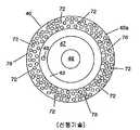
도 1A는 종래의 용량성 압력 변환기 조립체(100)의 부분 단면도이다. 도 1B는 도 1A의 상부 하우징(40), 다이아프램(56) 및 하부 하우징(60)의 분해 사시도이다. 간략히 말하면, 용량성 압력 변환기 조립체(10)는 내부 캐비티(cavity)를 형성하는 본체를 포함한다. 상대적으로 얇고 연질인 다이아프램(56)이 내부 캐비티를 밀폐된 제1 내부 챔버(52)와 밀폐된 제2 내부 챔버(54)로 분할한다. 이하에서 더 상세히 설명하는 바와 같이, 다이아프램(56)은 챔버(52)와 챔버(54)의 차압에 따라 휘거나 움직이거나 변형되도록 장착된다. 변환기 조립체(10)는 다이아프램의 휨 정도를 나타내는 파라미터를 제공하고, 따라서 이 파라미터는 챔버(52)와 챔버(54)의 차압을 간접적으로 나타낸다. 변환기 조립체(10)에 의해 제공되며 차압을 나타내는 파라미터는 다이아프램(56)과 상부 하우징(40) 상에 배치되는 하나 이상의 도체 사이의 전기용량이다.1A is a partial cross-sectional view of a conventional capacitive
용량성 압력 변환기 조립체(10)는 세라믹 상부 하우징(40), 세라믹 다이아프램(56) 및 세라믹 하부 하우징(60)을 포함한다. 위쪽에서 보았을 때 일반적으로 고리형인(circular shape) 상부 하우징(40)은 상부면(41), 중앙 하부면(47), 하부면(42a)을 가지는 환형 숄더(annular shoulder)(42) 및 중앙 하부면(47)과 환형 숄더(42) 사이에 위치하는 환형 채널(43)을 구비한다. 환형 숄더(42)의 하부면(42a)은 중앙 하부면(47)과 실질적으로 동일 평면상에 있다. 상부 하우징은 중앙 틈새(aperture)(또는 통로)(48)를 구비하는 압력관(44)를 추가로 포함하는데 중앙 틈새는 상부측에서 하부측까지 하우징(40)을 관통하여 연장된다. 금속 도체(46)는 하부면(47)의 중앙부 상에 배치된다.Capacitive
다이아프램(56)은 상부면(57) 및 반대편의 하부면(59)을 가지는 일반적으로 고리형인 얇은 다이아프램이다. 금속 도체(58)는 다이아프램(56)의 상부면(57)의 중앙부 상에 배치된다. 다이아프램(56)과 상부 하우징(40)은 상부 하우징(40)의 도체(46)가 다이아프램(56)의 도체(58)와 대향하도록 배치된다. 다이아프램(56)은 기밀(air-tight) 시일(또는 조인트)(70)에 의해 상부 하우징(40)에 체결되는데, 이하에서 더 상세히 설명한다. 시일(70)은 상부 하우징(40)의 환형 숄더(42)의 하부면(42a)과 이에 대응하는 다이아프램(56)의 상부면(57)의 환형부 사이에 위치한다. 밀폐될 때, 상부 하우징(40), 시일(70) 및 다이아프램(56)은 기준 챔버(52)를 형성한다. 압력관(44)의 틈새(48)는 기준 챔버(52) 내로의 입구 또는 도입 통로를 제공한다.
일반적으로 고리형인 하부 하우징은 상부면(62a)을 가지며 상위로 돌출된 환 형 숄더(62) 및 중앙 틈새(64)를 구비한다. 하부 하우징(60)의 숄더(62)의 상부면(62a)은 다이아프램(56)의 하부면(59)의 대응부에 기밀 시일(또는 조인트)(76)에 의해 체결된다. 시일(76)은 시일(70)과 유사하게 배치되고 제작될 수 있다. 밀폐될 때, 하부 하우징(60), 시일(76) 및 다이아프램(56)의 하부면(59)은 공정 챔버(54)를 형성한다.The generally annular lower housing has an
입구 통로(68)를 가지는 압력관(66)은 입구 통로(68)가 하부 하우징(60)의 개구(64)에 정렬하도록 하부 하우징(60)에 체결된다. 따라서, 공정 챔버(54)는 개구(64)와 입구 통로(68)를 통해 외부와 유체 소통을 한다. 작동 중에, 용량성 압력 변환기 조립체(10)가 외부 압력을 측정한다.The
용량성 압력 변환기 조립체(10)의 도체(46)와 도체(58)는 가변 커패시터(capacitor)(C)의 평행판을 형성한다. 알려진 바와 같이, C=Aεrεo/d 이다. C는 평행판 사이의 전기용량이고, A는 판 사이의 공유면적이며, εo는 진공상태의 유전율이고, εr는 판을 분리하는 재료의 상대 유전율(예를 들어 진공에 대해 εr=1)이며, d는 판 사이의 축방향 거리(즉, 판에 수직한 축선을 따라 측정한 판 사이의 거리)이다. 따라서, 커패시터(C)에 의해 제공되는 전기용량은 도체(46)와 도체(58) 사이의 축방향 거리의 함수이다. 챔버(52)와 챔버(54) 사이의 차압의 변화에 따라 다이아프램(56)이 상하로 움직이거나 휘면서, 커패시터(C)에 의해 제공되는 전기용량 또한 변한다. 임의의 순간에서, 커패시터(C)에 의해 제공되는 전기용량은 챔버(52)와 챔버(54) 사이의 순간 차압을 나타낸다. 공지된 전기 회로[예를 들어, 커패시터(C)에 의해 제공되는 전기용량의 함수인 공명 진동수로 특징지어지는 "탱크" 회로]가 커패시터(C)에 의해 제공되는 전기용량을 측정하고 차압을 나타내는 전기 신호를 제공하기 위해 이용될 수 있다. 도체(46)와 도체(58)는 예를 들어 금 또는 구리 같은 매우 다양한 전도성 재료로 이루어질 수 있고, 공지된 박막/후막 제조 공정 또는 다른 공지된 제조 방법을 통해 제조될 수 있다. 박막 제조 공정이 이용될 때, 도체(46, 48)는 예를 들어 약 1㎛의 두께를 가질 수 있다.
다이아프램(56)은 대개 산화 알루미늄으로 만들어진다. 그러나, 산화 유리 단결정 세라믹 재료같은 다른 세라믹 재료도 이용될 수 있다. 전기용량 센서는 미국 특허 제5,920,015호 및 제6,122,976호에 개시된 세라믹 구성 성분을 가질 수 있다.
작동 중에, 용량성 압력 변환기 조립체(10)는 보통 절대 압력 변환기로 이용된다. 이 경우, 기준 챔버(52)는 보통 압력관(44)에 진공 펌프(도시되지 않음)를 사용함으로써 첫 번째로 비워진다. 기준 챔버(52)가 비워지고 난 후 관(44)은 밀폐되어 챔버(52)의 진공 상태를 유지하도록 한다. "게터(getter)" 역시 관(44)에 연결되어 장기간동안 기준 챔버(52)의 진공 상태를 유지하도록 할 수 있다. 이로 인해 챔버(52)에서 "기준" 압력이 생성된다. 비록 진공 상태가 편리한 기준 압력이기는 하지만 다른 기준 압력이 이용될 수 있다. 기준 압력이 챔버(52)에서 확정되고 난 후, 압력관(66)이 유체의 압력을 측정할 수 있도록 유체 공급원(도시되지 않음)에 연결된다. 이 방법으로 압력관(66)을 체결하여 압력이 측정되는 유체를 공정 챔버(54)[및 다이아프램(56)의 하부면(59)]에 전달한다. 다이아프램(56)의 중앙부는 챔버(52)와 챔버(54) 사이의 차압에 따라 상하로 움직이거나 휘고 이에 따라 커패시터(C)의 전기용량이 변한다. 커패시터(C)의 순간 전기용량이 다이아프램(56)의 위상을 나타내기 때문에, 변환기 조립체(10)는 챔버(52)내의 압력에 대한 챔버(54)내의 상대적인 압력을 측정할 수 있다.In operation, the capacitive
변환기 조립체(10)은 또한 차압 변환기로도 당연히 이용될 수 있다. 이 경우, 압력관(44)은 제1 유체 공급원(도시되지 않음)에 연결되고 압력관(66)은 제2 유체 공급원(도시되지 않음)에 연결된다. 그 후 변환기 조립체(10)는 두 유체 사이의 차압을 측정할 수 있다. 선택적으로, 기준 챔버(52)는 대기압으로 유지되어 "게이지(gauge)" 변환기를 제공도록 할 수 있다.The
전술한 바와 같이, 챔버(52, 54) 사이의 차압의 변화는 다이아프램(56)을 휘게 하며 이에 따라 도체(46)와 도체(56) 사이의 간극(gap)이 변화한다. 간극의 변화를 측정하면 차압을 측정할 수 있다. 하지만 간극은 압력과 관계없는 요인에 영향받을 수도 있다. 예를 들어, 간극은 온도 변화에 영향받을 수 있다. 변환기 조립체(10)의 구성 성분은 다양한 재료로 만들어질 수 있으므로, 각 재료는 고유의 열 팽창 계수를 가지고, 주변 환경의 온도 변화는 다이아프램(56)을 도체(46)에 가까워지도록 또는 멀어지도록 움직이게 한다. 다행스럽게도, 온도 변화에 따른 간극의 변화는 차압의 변화에 따른 간극의 변화에 비해 각 재료의 특성에 따라 다르다. 주변 온도의 변화에 의한 간극의 변화를 보상하기 위해, 상부 하우징(40)의 하부면(47)상의 도체에 근접하여 배치된 제2 도체(도시되지 않음)를 포함하는 방법이 알려져 있다. 그러한 실시예에서, 도체(46)와 도체(58)는 가변 커패시터 C1의 평행판을 형성하고 도체(58)와 제2 도체는 가변 커패시터 C2의 평행판을 형성한다. 두 캐피시터 C1 및 C2는 온도 변화에 대한 변환기의 민감도를 감소시키기 위한 방법으로서 이용될 수 있다.As described above, the change in the differential pressure between the
상부 하우징(40)은 챔버(52, 54)내의 압력이 동일한 경우 도체(58)[즉, 다이아프램(56)]에 의해 구비되는 평면에 하부면(47) 및 하부면(47) 상에 배치된 어느 도체가 수평한 평면에 배치될 수 있도록 위치한다. 상술한 바와 같이, 도체(46, 58)에 의해 구비되는 커패시턴스는 이 도체 사이에 존재하는 간극(즉, 축방향 거리)에 종속한다. 상대적으로 작은[예를 들어, 0.0004인치(10~12㎛)] 간극은 부분적으로 시일(70)의 두께 및 상부 하우징의 형상 및 구조[예를 들어 하부면(42a)이 하부면(47)의 평면에서 벗어난 정도, 즉 오프셋 따위]에 종속한다.The
시일(70)과 시일(76)을 형성하는 방법은 미국 특허 제6,122,976호에 개시되어 있다. 이 방법에서, 시일은 두 표면 사이에 고체 유리 비드(bead)를 배치하고 두 표면 사이에 압축력을 가한 후 시일링 비드를 용융함으로써 형성된다. 용융 과정에서, 용융된 비드 유동은 두 표면 사이의 공간으로 흘러든다. 냉각 과정에서, 흘러든 시일 비드 재료는 두 표면 사이에서 시일을 형성한다.Methods for forming the
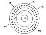
도 2는 도 1A 및 도 1B의 상부 하우징(40)의 저면도를 도시한다. 미국 특허 제6,122,976호와 같이 유리 입자는 결착제(binding agent) 및 용매(solvent)와 혼합되어 페이스트(paste) 재료를 형성한다. 그 후 페이스트 재료는 예를 들어 상부 하우징(40)의 숄더(42)의 하부면(42a) 및 하부 하우징(60) 시일이 형성되는 표면 상에 시일링 비드(72)의 패턴으로 용착된다. 시일링 비드(72)의 패턴은 적합한 스 크린 인쇄(screen-printing) 또는 패드/브러시 인쇄(pad/brush printing) 용착 공정을 이용하여 용착되고 형성될 수 있다. 이하에서 상세히 설명하는 바와 같이, 시일링 비드(72)는 개방 채널(78)이 시일링 비드(72) 사이에 존재하도록 용착된다. 시일링 비드(페이스트)(72)의 패턴이 표면에 용착되고 난 후, 시일링 비드(72)는 건조 공정, "번-오프(burn-off)" 공정 및 융해/소결(prefusion/sintering) 공정을 거친다. 각 단계에서, 시일링 비드(72)는 점점 더 높은 온도에 노출된다. 예를 들어, 시일링 비드(72)는 건조 공정 중 섭씨 100~150도로 가열될 수 있고 번-오프 공정 중 섭씨 325~375도로 가열될 수 있으며 융해/소결 공정 중 섭씨 490~500도로 가열될 수 있다. 용착된 시일링 비드(페이스트)(72)는 핸들링을 견딜 수 있도록 건조 공정에서 경화된다. 번-오프 공정 중에, 용매와 결착제 부분은 연소되어 페이스트가 된다. 만약 번-오프 공정이 적절히 수행되지 않으면, 시일은 불침투성(impermeable)이 아닐 수 있고 구조적으로 부적합할 수 있다. 시일링 비드(72)가 충분히 디가스(degas)(번-오프)되면, 온도가 더 증가하여 융해/소결 공정을 수행하도록 한다. 융해/소결 공정 중, 비드(72)에 존재하는 유리 입자는 서로 융해(fuse)된다. 그러나 비드(72)는 융해/소결 단계 중에 개방 채널(78) 내로 흘러들지 않는다. 융해/소결 단계 후, 시일링 비드(72)는 냉각된다. 냉각 후, 시일링 비드(72)는 시일링 비드가 바람직한 높이가 되도록 기계적으로 조작(예를 들어, 연마)된다. 몇몇 용례에서, (용융되지 않은) 시일링 비드(72)의 바람직한 높이는 예를 들어 20~24㎛가 될 수 있다.2 shows a bottom view of the
비드(72)가 용착된 패턴(도 2에 도시됨)은 비드(72)가 시일(70)[또는 시 일(76)]이 형성되는 중에 전체적으로 디가스되는 능력에 영향을 미친다. 시일링 비드(72)의 디가스를 용이하게 하기 위해, 시일링 비드(72) 사이에서 채널(78)과 함께 시일링 비드(72)를 용착하는 것이 유리할 수 있다. 그들 사이에 용착되는 시일링 비드(72)와 채널(78)의 단면의 디멘션은 바람직한 디가스 효과를 얻을 수 있도록 선택될 수 있다. 일 실시예에서, 시일링 비드(72)는 0.1~0.5㎜의 직경을 가지고 채널(78)은 같은 크기의 폭(width)을 가진다.The pattern in which the
시일링 비드(72)가 전술한 방식으로 용착되고 하부면(42a)와 상부면(62a) 상에 마련되면, 다이아프램(56)은 하부면(42a)상에 위치한 시일링 비드(72)가 다이아프램(56)의 상부면(57)의 시일링 구역과 접촉하도록 상부 하우징(40)과 정렬되고 하부 하우징(60)은 상부면(62a) 상에 위치한 시일링 비드(72)가 다이아프램(56)의 하부면(59)의 시일링 구역과 접촉하도록 다이아프램(56)과 정렬된다. 그 후 압축력이 상부 하우징(40), 다이아프램(56) 및 하부 하우징(60)에 다이아프램(56) 위치에 대체로 수직한 방향으로 가해진다. 그 후 더 높은 온도(즉, 융해/소결 단계 중의 온도보다 높은 온도)가 적용되어 시일링 비드(72)를 용융하도록 한다. 용융 과정 중, 시일링 비드(72)가 흘러들어 상부 하우징(40)의 숄더(42)와 다이아프램(56)의 상부 시일링 구역의 사이 및 하부 하우징(60)의 숄더(62)와 다이아프램(56)의 하부 시일링 구역의 사이에 틈새(void)[즉, 채널(78)]를 채우도록 한다. 냉각 과정 중, 시일링 비드(72)는 이에 따라 각각 다이아프램(56)과 상부 하우징(40)의 사이 및 다이아프램(56)과 하부 하우징(60)의 사이에 기밀 시일(70, 76)을 형성한다. 바람직한 높이(즉, 두께)와 면적을 가지는 시일(70)[및 시일(76)]을 형성하기 위 해, 용융되지 않은 시일링 비드(72)의 단면적과 높이는 시일링 비드(72) 재료의 총 부피가 바람직한 시일(70)을 형성하는데 충분하도록, 즉 시일링 비드(72)의 총 부피가 바람직한 시일(70)의 부피와 대체로 동일하도록 설정된다.When the sealing
용량성 압력 변환기의 도체가 서로간에 정밀하게 위치하거나 배치되지 않는다면 용량성 압력 변환기의 성능 특성에 안 좋은 영향을 미친다. 예를 들어, 도체(46, 58) 사이의 간극이 엄격한 치수 공차로 조절된 방식으로 설정되어 있지 않다면, 용량성 압력 변환기는 부적합한 성능 특성을 가질 수 있다. 더불어, 간극이 일관되게 조절될 수 없다면, 같은 성능 특성을 가지는 많은 수의 변환기를 제조하기 어렵게 된다.If the conductors of the capacitive pressure transducers are not precisely located or arranged with each other, this adversely affects the performance characteristics of the capacitive pressure transducers. For example, if the gap between
상술한 시일링 방법은 형성된 시일(70)이 정밀하고 일정한 두께를 가지도록 반드시 보증하는 것은 아니다. 예를 들어, 시일(70)은 만약 과도하거나 불충분한 양의 시일링 비드(72) 재료가 시일(70)을 형성하기 위해 사용되었다면 너무 두껍거나 너무 얇을 수 있다. 또한, 용융 과정과 냉각 과정 중에 상부 하우징(40)과 다이아프램(56) 사이에 가해지는 압축력이 일정하지 않다면 시일(70)의 두께는 일정하지 않을 수 있다.The aforementioned sealing method does not necessarily guarantee that the formed
따라서 용량성 압력 변환기의 하우징과 다이아프램 사이에서 시일을 정밀하게 형성하는 방법에 대한 필요성이 있게 된다.Thus, there is a need for a method of precisely forming a seal between the diaphragm and the housing of the capacitive pressure transducer.
본 발명은 용량성 압력 변환기의 하우징과 다이아프램 사이에서 시일을 정밀하게 형성하는 방법 및 시스템에 대한 것이다. 특정 용량성 압력 변환기에서, 용량성 압력 변환기의 대향하는 도체 사이의 축방향 거리는 하우징과 다이아프램 사이에 용착되는 시일의 두께에 부분적으로 종속한다. 설명하듯이, 고온 및 저온의 시일링 비드가 정밀하고 일정한 두께를 가지는 시일을 형성하는 데 이용된다. 정밀하고 일정한 두께를 가지는 시일을 이용함으로써, 용량성 압력 변환기의 대향하는 도체는 제조 공정 중에 서로에 대한 관계에서 정밀하게 위치하고 배치될 수 있다.The present invention is directed to a method and system for precisely forming a seal between a diaphragm and a housing of a capacitive pressure transducer. In certain capacitive pressure transducers, the axial distance between the opposing conductors of the capacitive pressure transducer depends in part on the thickness of the seal deposited between the housing and the diaphragm. As explained, hot and cold sealing beads are used to form a seal with precise and constant thickness. By using a seal having a precise and constant thickness, the opposing conductors of the capacitive pressure transducer can be precisely located and placed in relation to each other during the manufacturing process.
일 실시예에서, 고온 시일링 비드의 높이가 소정의 높이로 설정된다. 그 후 저온 시일링 비드가 고온 시일링 비드의 사이 및 주변에서 용착된다. 저온 시일링 비드 및 고온 시일링 비드는 저온 시일링 비드를 용융하기에는 충분하지만 고온 시일링 비드를 용융하기에는 불충분한 온도에 노출된다. 용융된 저온 시일링 비드가 용융되지 않은 고온 시일링 비드 주변에서 흐른다. 응고 과정에서, 저온 시일링 비드 및 고온 시일링 비드는 함께 시일을 형성한다. 고온 시일링 비드가 시일 제작 공정에서 용융되지 않기 때문에, 시일 두께는 용융되지 않은 고온 시일링 비드의 높이를 조절함으로써 설정될 수 있다. 완성된 시일에서, 시일의 형성 과정에서 용융되어 흐르는 저온 시일링 비드는 고온 시일링 비드 주변에 충족하여 배치되는 저온 재료로 변한다. "충족하여 배치되는(conformally disposed)"이라 함은 저온 재료가 고온 시일링 비드 주변에서 흐르고 저온 재료의 틈새가 고온 비드 재료로 구비되고 채워지는 것을 의미한다. 하지만, 저온 재료에 채워지지 않은 틈새가 존재할 수 있다(예를 들어, 고온 시일링 비드와 저온 재료 사이의 경계에서). 비록 이러한 틈새가 존재하지 않도록 하는 것이 바람직하지만, 틈새가 충분히 적고 틈새의 수가 작은 한 틈새가 있다고 하여 시일의 무결성(integrity)을 해하는 것이 아니고, 또한 저온 재료가 고온 시일링 비드 주변에서 충족하여 배치되지 않았다는 것을 의미하는 것이 아니다.In one embodiment, the height of the hot sealing beads is set to a predetermined height. The cold sealing beads are then deposited between and around the hot sealing beads. The low temperature sealing beads and the high temperature sealing beads are sufficient to melt the low temperature sealing beads but are exposed to an insufficient temperature to melt the high temperature sealing beads. The molten cold sealing beads flow around the unmelted hot sealing beads. In the solidification process, the low temperature sealing beads and the high temperature sealing beads together form a seal. Since the hot sealing beads are not melted in the seal fabrication process, the seal thickness can be set by adjusting the height of the unmelted hot sealing beads. In the finished seal, the low temperature sealing beads which melt and flow during the formation of the seals turn into low temperature materials which are disposed satisfactorily around the high temperature sealing beads. By "conformally disposed" it is meant that the cold material flows around the hot sealing bead and the gap of the cold material is provided and filled with the hot bead material. However, there may be an unfilled gap in the low temperature material (eg at the boundary between the hot sealing bead and the low temperature material). Although it is desirable to ensure that these gaps do not exist, the presence of a gap with a small enough gap and a small number of gaps does not compromise the integrity of the seal, nor does the low temperature material meet and be placed around the hot sealing bead. It does not mean that it did.
참조 번호로 구성 요소를 지시하는 첨부 도면을 고려하여 이하의 설명을 참조하면 본 발명의 다양한 목적, 특징, 이점이 더욱 명확해 질 것이다. 첨부 도면은 설명을 위한 목적이 있을 뿐 본 발명을 제한하는 의도가 없으며, 발명의 사상은 이어지는 청구항에서 나타난다.Various objects, features, and advantages of the present invention will become more apparent with reference to the following description in view of the accompanying drawings in which components are designated by reference numerals. The accompanying drawings are for purposes of illustration only and are not intended to limit the invention, the spirit of the invention is shown in the following claims.
도 1A는 종래 기술의 용량성 센서의 횡단면도.1A is a cross-sectional view of a capacitive sensor of the prior art.
도 1B는 도 1A의 종래 기술의 용량성 센서의 부분적인 확대된 횡단면도.1B is a partially enlarged cross-sectional view of the prior art capacitive sensor of FIG. 1A.
도 2는 용량성 센서의 하우징 상에 시일을 형성하기 위해 하우징과 다이아프램 사이에서 시일링 비드가 용착되는 과정을 도시하는 도면.2 shows the process by which sealing beads are welded between the housing and the diaphragm to form a seal on the housing of the capacitive sensor.
도 3A는 본 발명에 따라 구성된 용량성 센서의 일실시예에 대한 횡단면도.3A is a cross-sectional view of one embodiment of a capacitive sensor constructed in accordance with the present invention.
도 3B는 도 3A의 용량성 센서의 부분적인 확대된 횡단면도.3B is a partially enlarged cross-sectional view of the capacitive sensor of FIG. 3A.
도 4는 용량성 센서의 하우징 상으로 고온 시일링 비드를 용착하는 예시적인 방법을 도시하는 도면.4 illustrates an exemplary method of depositing high temperature sealing beads onto a housing of a capacitive sensor.
도 5는 용량성 센서의 하우징 상으로 저온 시일링 비드를 용착하는 예시적인 방법을 도시하는 도면.5 illustrates an exemplary method of depositing low temperature sealing beads onto a housing of a capacitive sensor.
도 6은 용량성 센서의 하우징과 다이아프램 사이에서 시일을 형성하는 예시적인 방법의 일 단계를 도시하는 도면.FIG. 6 illustrates one step of an exemplary method of forming a seal between a diaphragm and a housing of a capacitive sensor. FIG.
도 7은 용량성 센서의 하우징과 다이아프램 사이에서 시일을 형성하는 예시적인 방법의 또 다른 단계를 도시하는 도면.FIG. 7 illustrates yet another step of an exemplary method of forming a seal between a diaphragm and a housing of a capacitive sensor.
도 8은 본 발명에 따라 용량성 센서의 하우징과 다이아프램 사이에서 형성되는 예시적인 시일의 확대도.8 is an enlarged view of an exemplary seal formed between the diaphragm and the housing of the capacitive sensor in accordance with the present invention.
도 9는 용량성 센서의 하우징과 다이아프램 사이에서 시일을 형성하는 예시적인 방법의 일 단계를 도시하는 도면.9 illustrates one step of an exemplary method of forming a seal between a diaphragm and a housing of a capacitive sensor.
도 10은 용량성 센서의 하우징과 다이아프램 사이에서 시일을 형성하는 예시적인 방법의 또 다른 단계를 도시하는 도면.10 shows yet another step of an exemplary method of forming a seal between a diaphragm and a housing of a capacitive sensor.
도 11은 본 발명에 따라 용량성 센서의 하우징과 다이아프램 사이에서 형성되는 예시적인 시일의 확대도.11 is an enlarged view of an exemplary seal formed between the housing and diaphragm of the capacitive sensor in accordance with the present invention.
본 발명은 용량성 압력 변환기의 하우징과 다이아프램 사이에서 시일을 정밀하게 형성하는 방법 및 시스템에 대한 것이다. 본 발명은 고온 및 저온 시일링 비드를 이용하여 정밀하고 균일하며 일정한 두께를 가지는 액밀(fluid-tight) 시일을 형성하는 방법을 제공하는 데 있다. 제어된 두께를 가지는 시일을 형성함으로써, 대향하는 도체 사이의 축방향 거리는 정밀하게 제어될 수 있다.The present invention is directed to a method and system for precisely forming a seal between a diaphragm and a housing of a capacitive pressure transducer. The present invention provides a method of forming a fluid-tight seal having a precise, uniform and constant thickness using high and low temperature sealing beads. By forming a seal with a controlled thickness, the axial distance between the opposing conductors can be precisely controlled.
도 3A는 본 발명에 따른 예시적인 용량성 압력 변환기 조립체(100)의 횡단면도를 도시한다. 선행 기술의 용량성 압력 변환기 조립체(10)와 같이, 조립체(100)는 상부 하우징(40), 다이아프램(56) 및 하부 하우징(60)을 포함한다. 도 3B는 도 3A에 도시된 조립체(100)의 상부 하우징(40), 다이아프램(56) 및 하부 하우징(40)의 분해 횡단면도이다. 선행 기술의 변환기 조립체(10)와 다르게, 조립체(100)는 다이아프램(56)과 상부 하우징(40) 사이에 배치된 개선된 시일(170)을 포함한다. 시일링될 때, 상부 하우징(40), 시일(170) 및 다이아프램(56)은 기준 챔버(152; 제1 챔버)를 형성한다.3A shows a cross-sectional view of an exemplary capacitive
유사하게, 개선된 시일(176)이 다이아프램(56)과 하부 하우징(60) 사이에 마련될 수 있다. 시일링될 때, 하부 하우징(60), 시일(176) 및 다이아프램(56)은 공정 챔버(154; 제2 챔버)를 형성한다.Similarly, an
시일(170)은 고온 및 저온 시일링 비드를 이용하여 형성된다. 고온 시일링 비드의 용융 온도는 저온 시일링 비드의 용융 온도보다 높다. 저온 시일링 비드의 용융점보다 더 높은 용융점을 갖는 고온 시일링 비드를 마련하기 위해, 고온 및 저온 시일링 비드는 다른 재료로 구성되거나 같은 재료의 다른 조성을 가질 수 있다.
형성된 시일(170)은 정밀하고 일정한 두께를 가진다. 정밀하고 일정한 두께를 가지는 시일을 이용함으로써, 용량성 압력 변환기의 대향하는 도체는 제조 공정 중에 서로에 대한 관계에서 정밀하게 위치하고 배치될 수 있다.The formed
도 4는 상부 하우징(40)의 숄더(42)의 하부면(42a)에 용착된 다수의 고온 시일 비드(172; 비드의 제1 세트, 제1 요소)를 도시한다. 도시된 바와 같이, 고온 시일링 비드(172)는 숄더(42)의 하부면(42a)에 균일하게 분포한다. 고온 시일 비드(172)는 유리 재료로 구성되고 시일링 비드(72)가 용착되는(도 2와 연결하여 상술한 바와 같이) 방법과 유사한 방법으로 용착되고 가공된다. 예를 들어 고온 시일 비드(172)는 기술 분야에서 널리 알려진 프린팅 공정을 통해 용착되고, 그 후 고온 시일 비드(172)는 열을 가함으로써 건조되며, 고온 시일 비드(172)에 함유된 용매와 결착제의 대부분은 고온 시일 비드(172)를 고온에 노출시켜 번-오프 되고, 그 후 고온 시일 비드(172)는 고온 시일 비드(172)를 더 높은 온도에 노출시킴으로써 융해/소결 공정을 거친다. 융해/소결 단계 후, 고온 시일링 비드(172)는 냉각되어 응고한다. 고온 시일링 비드(172)는 고온 페이스트를 비드(172)로서 용착하고, 비드(172)를 40℃/분의 비율로 125℃까지 증가하는 램핑(ramping) 온도에 노출시키며, 125℃에서 15분간 유지시키고, 비드(172)를 40℃/분의 비율로 720℃까지 증가하는 램핑 온도에 노출시키며, 720℃에서 10분간 유지시키고, 그 후 40℃/분의 비율로 온도를 램핑 다운시켜 형성된다. 형성되는 고온 시일링 비드(172)의 용융 온도는 약 725℃이다.4 shows a plurality of high temperature seal beads 172 (first set of beads, first element) deposited on the
고온 시일 비드(172)는 시일(170)의 형성 중에 용융되지 않는다(즉, 액체 상태로 흘러들지 않는다). 그 대신, 고온 시일링 비드(172)는 시일(170)의 두께를 결정하는 스페이서(spacer)처럼 행동한다. 다시 말해서, 서로 시일링될 두 표면 사이에서 연장되는 받침부(pedestal)처럼 행동함으로써, 고온 시일 비드(172)는 시일(170)의 두께를 설정한다. 소정의(그리고 일정한) 두께를 가지는 시일(170)을 마련하기 위해, 고온 시일 비드(172)가 소정의 두께와 동일한 비드 높이를 갖는 것이 중요하다. 시일(170)이 바람직한 두께를 가지도록 보장하는 하나의 간단한 방법은 시일(170)의 바람직한 두께보다 두꺼운 고온 시일링 비드(172)를 가지고 시작하는 것이다. 비드(172)가 숄더(42) 상에 용착되고 난 후, 비드(172)는 두께(즉, 높이)가 시일(170)의 바람직한 두께에 맞추어 연마된다. 예를 들어 시일(170)의 소정의 두께는 약 10~12㎛일 수 있다.The
래핑/연마 기술에 추가하여, 고온 시일링 비드(172)의 높이는 또한 예를 들어 기술 분야에서 널리 알려진 에칭(etching), 반응 이온 에칭(reactive ion etching)(건식 에칭) 또는 레이저 제거 기술(laser ablation technique)을 이용하여 정해질 수 있다. 고온 시일 비드(172)의 높이는 예를 들어 기술 분야에서 알려진 강하 표시기(drop indicator) 측정, 레이저 측정 또는 목표-전기용량(target-capacitance) 측정 기술에 의해 측정될 수 있다.In addition to the lapping / polishing techniques, the height of the
도 5를 참조하면, 고온 시일 비드(172)가 숄더(42)의 하부면(42a) 상에 용착되어 형성되고 비드 높이가 정해지고 나면, 저온 시일링 비드(174; 비드의 제2 세트)가 하부면(42a) 상의 고온 시일링 비드(172) 사이 및 주변에서 용착된다. 저온 시일링 비드(174)는 고온 시일링 비드(172)의 용융점에 비해 더 낮은 용융점을 갖는다. 저온 시일링 비드(174)가 용착되는 표면 상에 저온 시일링 비드(174)를 균일하게 분포시키는 것이 유리할 수 있다. 도 4 및 도 5의 고온 시일 비드(172)와 저온 시일링 비드(174)가 상부 하우징(40)의 숄더(42)의 하부면(42a) 상에 용착되어 형성되는 것으로 도시된 반면에, 고온 시일 비드(172)와 저온 시일링 비드(174)는 그 대신에 다이아프램(56)의 상부면(57)의 시일링 구역 상에 용착되고 형성될 수 있다. 저온 시일 비드(174)는 바람직하게 유리 재료로 이루어지고 전술한 바와 같은 고온 시일링 비드(172)의 경우 같은 방식(다른 가공 온도를 가지고)으로 용착되고 가공된다.Referring to FIG. 5, after the
저온 시일링 비드(174)는 고온 시일링 비드(172) 사이 및 주변에서 용착되어 저온 시일링 비드(174)와 고온 시일링 비드(172) 사이의 개방 채널(178)을 남겨둔다. 개방 채널(178)이 존재함으로써 저온 시일링 비드(174)가 마지막 시일링(용융 과정과 냉각 과정) 단계 중에 적절하게 디가스되도록 한다. 저온 시일링 비드(174)가 용착되고 난 후(예를 들어 전술한 건조, 번-오프 및 융해/소결 단계 후), 상부 하우징(40)과 다이아프램(56)을 함께 압축하고 저온 시일링 비드(174)를 용융하며 고온 시일링 비드(172)를 용융하지 않기에 충분한 열을 가함으로써 시일(170)이 형성된다.The
저온 시일링 비드(174)가 용융될 때, 저온 시일링 비드(174)는 저온 재료를 형성하는데, 저온 재료 부분이 개방 채널(178) 내로 흘러들고 개방 채널(178)을 차지한다. 따라서, 용융되지 않은 고온 시일링 비드(172)와 함께 저온 시일링 비드(174)는 시일(170)을 형성한다. 개방 채널을 구비하면서, 적절한 양(즉, 부피)의 저온 시일링 비드(174) 재료가 상부 하우징(40)의 숄더(42) 상에 용착되는 것이 중요하며, 이는 용융 과정 중에 저온 시일링 비드(174) 재료가[고온 시일링 비드(172)의 부피와 함께] 시일(170)이 차지하는 공간을 적절하게 채우도록 하기 위함이다. 따라서, 저온 시일링 비드(174)를 용융하기에 앞서 저온 시일링 비드(174)도 특정 비드 높이를 가지도록 보증하는 것이 바람직하다.When the
따라서, 저온 시일 비드(174)가 냉각되고 난 후(즉, 건조, 번-오프 및 융해/소결 과정을 거친 후), 각 저온 시일 비드(174)의 비드 높이는 측정될 수 있으며 목표 저온 비드 높이와 비교될 수 있다. 저온 시일 비드(174)의 측정된 비드 높이가 목표 저온 비드 높이를 초과한다면, 저온 시일 비드(174)는 목표 저온 비드 높이와 동일하도록 연마된다. 목표 저온 비드 높이보다 낮은 비드 높이를 가지는 저온 시일 비드(174)를 예방하기 위해, 목표 비드 높이를 초과하는 비드 높이를 가지 는 저온 시일 비드(174)를 표면 상에 용착하는 것이 유용할 수 있다. 저온 시일링 비드(174)가 용융되어 개방 채널(178)을 채우도록 할 것이므로, 목표 저온 비드 높이가 대체로 목표 고온 비드 높이보다 높다. 예를 들어, 목표 저온 비드 높이는 목표 고온 비드 높이의 두 배일 수 있다.Thus, after the
도 6 및 도 7을 참조하면, 고온 시일링 비드(172)와 저온 시일링 비드(174)가 상부 하우징(40)의 하부면(42a) 상에 용착되고 형성되면, 다이아프램(56)은 저온 시일링 비드(174)가 상부 하우징(40)의 숄더(42)에서 다이아프램(56)의 시일링 구역으로 연장되도록 상부 하우징(40)과 정렬된다. 압축력(F)이 상부 하우징(40)과 다이아프램(56) 사이에 다이아프램(56)의 위치에 실질적으로 수평한 방향으로 가해져서 상부 하우징(40)이 다이아프램에 대해 적절한 관계를 유지하도록 한다. 압축력(F)은 상부 하우징(40)의 윗면에 충분한 질량(즉, 무게)를 놓아 발생시킬 수 있고, 또는 선택적으로 상부 하우징(40)과 다이아프램(56) 사이에 예를 들어 프레스를 통해 힘을 가하여 발생시킬 수 있다. 압축력(F)이 존재함으로써 저온 시일링 비드(174)가 용융될 때 저온 시일링 비드(174)가 개방 채널(178)로 흘러들어 개방 채널(178)을 채우고, 고온 시일링 비드(172)가 다이아프램(56)의 상부면(57)과 접하도록 하는데 도움이 된다.6 and 7, when the
다이아프램(56)이 상부 하우징(40)과 정렬되고 난 후(도 6), 저온 시일링 비드(174)는 저온 시일링 비드(174)의 용융점보다 높지만 고온 시일링 비드(172)의 용융점보다 낮은 온도에 노출된다. 용융 과정 중, 저온 시일링 비드(174)는 개방 채널(178)로 흘러 들고 개방 채널(178)을 채운다. 냉각 과정 중, 먼저 용융된 저 온 시일링 비드(174)는 고온 시일링 비드(172)와 함께 시일(170)을 형성한다(도 7). 고온 시일링 비드(172)의 용융점보다 낮게 온도가 유지되었기 때문에, 용융되지 않은 고온 시일링 비드(172)의 비드 높이(h)가 시일(170)의 두께를 정한다. 따라서, 용융되지 않은 고온 시일링 비드(172)의 비드 높이(h)를 일정한 높이로 설정함으로써, 시일(170)은 정밀하고 균일한 두께를 가지도록 형성될 수 있다. 또한, 시일(170)의 두께는 시일링 구역을 가로질러 압축력(F)이 불균일하게 가해지더라도 악영향을 받지 않는다.After the
도 8은 용량성 압력 변환기 조립체(100)의 도체(46, 58; 제1 도체 및 제2 도체) 사이에 존재하는 간극(g)(즉, 축방향 거리)이 어떻게 시일(170)의 두께에 부분적으로 종속하는지 도시한다. 전술한 바와 같이, 하부면(42a)과 상부 하우징(40)의 면(47)은 실질적으로 동일 평면상에 있다. 상부 하우징(40)은 챔버(152, 154)내의 압력이 동일할 때 상부 하우징(40)의 면(47)이 다이아프램(56)의 면(57)에 수평하도록 위치한다. 챔버(152, 154) 내의 압력이 동일할 때, 다이아프램(56)에 작용하는 차압은 "0"이고 따라서 다이아프램(56)은 압력으로 인해 유발되는 어떠한 변형도 받지 않는다. 도 8에 도시된 바와 같이, 챔버(152, 154) 내의 압력이 동일하면, 도체(46, 58) 사이의 간극(g)은 시일(170)의 두께[고온 시일링 비드(172)의 비드 높이(h)와 동일함]에서 도체(46, 58)의 두께를 뺀 값으로 이루어진다.8 illustrates how the gap g (ie, axial distance) existing between the
하지만, 차압이 다이아프램(56)에 가해지는 경우 다이아프램(56) 부분이 차압에 대응하여 변형할 것이다. 따라서 간극(g)은 차압 크기 및 방향에 종속하여 증가하거나 감소한다. 예를 들어, 공정 챔버(154)의 압력이 기준 챔버(152)의 압 력보다 높게 증가하는 경우, 다이아프램(56) 부분이 상부 하우징(40)의 면(47)을 향해 변형할 것이고, 따라서 도체(46, 58) 사이의 간극(g)이 감소할 것이다. 선택적으로, 공정 챔버(154) 내의 압력이 기준 챔버(152) 내의 압력보다 낮게 감소하는 경우, 다이아프램(56) 부분이 상부 하우징(40)의 면(47)에서 멀어지도록 변형할 것이고, 따라서 도체(46, 58) 사이의 간극(g)이 증가할 것이다.However, when differential pressure is applied to the
시일(170)의 두께와 도체(46, 58)의 두께에 종속하는 간극(g)을 제공하는 대신에, 시일(170)의 두께와 실질적으로 동일한 간극(g)을 가지는 전기용량 압력 변환기 조립체를 제공하는 것이 유용할 수 있다. 도 9 내지 11은 시일(170)의 두께와 실질적으로 동일한 간극을 가지는 전기용량 압력 변환기 조립체(200)의 부분 횡단면도를 도시한다. 조립체(200)는 층(246)이 숄더(42)의 하부면(42a) 상에 배치되고 층(258)이 다이아프램(56)의 상부면(57) 상에 배치된다는 점을 제외하고 조립체(100)와 유사하다. 도 9에 도시된 바와 같이, 층(246, 258)은 각각 시일(170)이 형성되는 하부면(42a)과 상부면(57) 상에 배치된다. 밀폐될 때, 상부 하우징(40), 시일(170), 층(246, 258) 및 다이아프램(56)은 기준 챔버(252)를 형성한다. 층(246)이 도체(46)의 두께와 실질적으로 동일한 두께를 가지는 동시에 층(258)은 도체(58)의 두께와 실질적으로 동일한 두께를 가진다. 층(246)은 하부면(47) 상에 도체(46)가 형성되는 동시에 하부면(42a) 상에 형성될 수 있고, 도체(46)의 재료와 같은 재료로 이루어질 수 있다. 층(258)은 유사하게 도체(58)이 상부면(57) 상에 형성되는 동시에 상부면(57) 상에 형성될 수 있고, 또한 도체(58)의 재료와 같은 재료로 이루어질 수 있다. 층(246)이 숄더(42)의 하부면(42a) 상에 배치되고 난 후, 고온 시일링 비드(172)[비드 높이(h)를 가짐)와 저온 시일링 비드(174)는 전술한 기술에 따라 층(246) 상에 용착되고 형성될 수 있다.Instead of providing a gap g dependent on the thickness of the
다이아프램(56)이 상부 하우징(40)과 정렬되고(도 9) 압축력(F)가 가해지고 난 후, 저온 시일링 비드(174)가 용융된다. 냉각되는 중에, 저온 시일링 비드(174)는 고온 시일링 비드(172)와 함께 층(246, 258) 사이에 위치하는 시일(170)을 형성한다(도 10). 도 11에서 도시된 바와 같이, 층(246, 258)의 두께가 각각 도체(46, 58)의 두께와 실질적으로 동일하기 때문에, 챔버(252, 154) 내의 압력이 동일할 때, 도체(46, 58) 사이에 존재하는 간극(g)은 시일(170)의 두께와 실질적으로 동일하다. 형성된 시일(170)의 두께가 고온 시일링 비드(172)의 비드 높이(h)에 의해 설정되기 때문에, 조립체(200)의 간극(g)은 비드 높이(h)와 동일하고 비드 높이(h)에 의해 제어된다.After the
층(246,258)은 전도성 또는 비전도성 재료로 이루어질 수 있다. 전도성 재료가 이용되는 경우, 층(246, 258)은 또한 도체(46, 58)의 전기용량 가드(capacitance guard)처럼 이용될 수 있다.
제작된 상부 하우징(40)과 다이아프램(56)의 공차를 제조하는 공정이 이들 센서 구성 성분의 제조 과정 중 공지된 방식으로 제어될 수 있으므로, 그러한 구성 성분 사이에서 시일을 형성하는 본 발명을 이용함으로써, 대향하는 도체 사이의 축방향 거리는 정밀하고 균일하며 일정한 방식으로 정해질 수 있다. 정밀하고 균일하며 일정한 두께를 가지는 시일(170)을 제공함으로써, 본 발명은 일정하고 신뢰할 만한 성능 특성을 가지는 변환기 조립체를 제공하는데 이용될 수 있다.Since the process of manufacturing the tolerances of the fabricated
조립체(100, 200)의 상부 하우징(40)은 하부면(42a)과 실질적으로 동일 평면상에 있는 중앙 하부면(47)을 가진다. 다른 전기용량 압력 변환기 조립체에서, 상부 하우징(40)의 중앙 하부면(47)은 숄더(42)의 하부면(42a)에서 어느 정도의 거리를 차감(offset)할 수 있다. 따라서, 다이아프램의 양 측의 챔버 내의 압력이 동일할 때, 도체(46, 58) 사이에 존재하는 간극(g)은 시일(170)의 두께와 하부면(42a)에서 면(47)이 차감하는 정도에 종속할 수 있다. 하지만, 일반적으로 동일 평면상의 표면이 동일 평면상에 있지 않은 표면(예를 들어, 서로 수평하지만 차감하는 표면)에 비해 더 엄격한 공차로 제작될 수 있기 때문에, 하부면(42a)과 실질적으로 동일 평면상에 있는 중앙 하부면(47)을 가지는 상부 하우징(40)을 이용하는 것이 유용할 수 있다.The
도 4 및 도 5의 저온 시일링 비드(174)와 고온 시일링 비드(172)가 고리형 단면을 가지는 것으로 도시되어 있지만, 저온 시일링 비드(174)와 고온 시일링 비드(172)의 단면은 정사각형, 평행사변형, 마름모 또는 평행육면체 형상(예를 들어 서로 인접하게 위치하는 점들을 가지는), 육각형 또는 매우 다양한 적합한 형상일 수 있다. 저온 시일링 비드(174)와 고온 시일링 비드(172)의 단면 형상은 같을 필요가 없다.Although the
본 발명은 상부 하우징(40), 다이아프램(56) 및 하부 하우징(60)이 모두 세라믹 재료(예를 들어, 산화 알루미늄)로 이루어진 세라믹 압력 변환기 조립체와 관련하여 이상 설명되었다. 하지만, 다른 재료들이 본 발명에서 벗어나지 아니하고 이용될 수 있다.The present invention has been described above in connection with a ceramic pressure transducer assembly in which the
본 발명의 교시를 통합하는 다양한 실시예들이 도시되고 상세히 설명되었지만, 당업자들은 상기 교시를 통합하는 다른 다수의 다양한 실시예를 고안할 수 있다.While various embodiments incorporating the teachings of the present invention have been shown and described in detail, those skilled in the art can devise many other various embodiments incorporating the teachings.
Claims (42)
Translated fromKoreanApplications Claiming Priority (3)
| Application Number | Priority Date | Filing Date | Title |
|---|---|---|---|
| US10/960,158US7141447B2 (en) | 2004-10-07 | 2004-10-07 | Method of forming a seal between a housing and a diaphragm of a capacitance sensor |
| US10/960,158 | 2004-10-07 | ||
| PCT/US2005/035167WO2006041719A2 (en) | 2004-10-07 | 2005-10-03 | Method of forming a seal between a housing and a diaphragm of a capacitance sensor |
Publications (2)
| Publication Number | Publication Date |
|---|---|
| KR20070063029A KR20070063029A (en) | 2007-06-18 |
| KR101259652B1true KR101259652B1 (en) | 2013-04-30 |
Family
ID=36026923
Family Applications (1)
| Application Number | Title | Priority Date | Filing Date |
|---|---|---|---|
| KR1020077010352AExpired - LifetimeKR101259652B1 (en) | 2004-10-07 | 2005-10-03 | Method of forming a seal between a housing and a diaphragm of a capacitance sensor |
Country Status (5)
| Country | Link |
|---|---|
| US (2) | US7141447B2 (en) |
| EP (1) | EP1800099A2 (en) |
| JP (1) | JP5248112B2 (en) |
| KR (1) | KR101259652B1 (en) |
| WO (1) | WO2006041719A2 (en) |
Families Citing this family (31)
| Publication number | Priority date | Publication date | Assignee | Title |
|---|---|---|---|---|
| US7141447B2 (en) | 2004-10-07 | 2006-11-28 | Mks Instruments, Inc. | Method of forming a seal between a housing and a diaphragm of a capacitance sensor |
| US7137301B2 (en) | 2004-10-07 | 2006-11-21 | Mks Instruments, Inc. | Method and apparatus for forming a reference pressure within a chamber of a capacitance sensor |
| US7383737B1 (en)* | 2007-03-29 | 2008-06-10 | Delphi Technologies, Inc | Capacitive pressure sensor |
| EP2155287B1 (en)* | 2007-05-15 | 2017-10-04 | Gambro Lundia AB | Pressure sensing device and use of the same in a connecting structure |
| US20090057376A1 (en)* | 2007-08-29 | 2009-03-05 | Honeywell International Inc. | Automated evacuation and sealing process |
| US7841240B2 (en)* | 2008-04-16 | 2010-11-30 | Kulite Semiconductor Products, Inc. | Header for a differential pressure transducer |
| FR2947629B1 (en)* | 2009-07-06 | 2012-03-30 | Tronic S Microsystems | PRESSURE MEASURING DEVICE AND METHOD FOR MANUFACTURING THE SAME |
| US8468894B2 (en)* | 2009-11-02 | 2013-06-25 | Vega Grieshaber Kg | Measuring cell and a method of use therefor |
| CN102812342B (en) | 2010-02-02 | 2014-11-26 | Mks仪器公司 | Capacitive pressure sensor |
| DE102010043119A1 (en)* | 2010-10-29 | 2012-05-03 | Endress + Hauser Gmbh + Co. Kg | Method for producing a connection between two ceramic parts, in particular parts of a pressure sensor, and a ceramic product, in particular a ceramic pressure sensor |
| US8261618B2 (en)* | 2010-11-22 | 2012-09-11 | General Electric Company | Device for measuring properties of working fluids |
| DE102011081887A1 (en)* | 2011-08-31 | 2013-02-28 | Robert Bosch Gmbh | Polymer layer system pressure sensor device and polymer layer system pressure sensor method |
| EP2761265B1 (en) | 2011-09-29 | 2019-11-06 | MKS Instruments, Inc. | Capacitive pressure sensor with improved electrode structure |
| TWI532982B (en) | 2011-10-11 | 2016-05-11 | Mks公司 | Pressure sensor |
| US9194760B2 (en) | 2013-03-14 | 2015-11-24 | Dwyer Instruments, Inc. | Capacitive pressure sensor with reduced parasitic capacitance |
| DE102014012918B4 (en) | 2014-09-05 | 2019-01-03 | Heinz Plöchinger | Dual-capacity pressure gauge with a small measuring volume |
| EP3203203B1 (en)* | 2014-10-03 | 2018-12-19 | TLV Co., Ltd. | Sensor device |
| US11043444B2 (en) | 2018-08-10 | 2021-06-22 | Frore Systems Inc. | Two-dimensional addessable array of piezoelectric MEMS-based active cooling devices |
| US11464140B2 (en) | 2019-12-06 | 2022-10-04 | Frore Systems Inc. | Centrally anchored MEMS-based active cooling systems |
| US12089374B2 (en) | 2018-08-10 | 2024-09-10 | Frore Systems Inc. | MEMS-based active cooling systems |
| KR102677216B1 (en) | 2019-10-30 | 2024-06-24 | 프로리 시스템스 인코포레이티드 | MEMS-based airflow system |
| US11796262B2 (en) | 2019-12-06 | 2023-10-24 | Frore Systems Inc. | Top chamber cavities for center-pinned actuators |
| US11510341B2 (en) | 2019-12-06 | 2022-11-22 | Frore Systems Inc. | Engineered actuators usable in MEMs active cooling devices |
| US12193192B2 (en) | 2019-12-06 | 2025-01-07 | Frore Systems Inc. | Cavities for center-pinned actuator cooling systems |
| JP7333417B2 (en) | 2019-12-17 | 2023-08-24 | フロー・システムズ・インコーポレーテッド | MEMS-based cooling system for closed and open devices |
| US12033917B2 (en) | 2019-12-17 | 2024-07-09 | Frore Systems Inc. | Airflow control in active cooling systems |
| US11287342B2 (en) | 2020-03-20 | 2022-03-29 | Mks Instruments, Inc. | Capacitance manometer with improved baffle for improved detection accuracy |
| US11765863B2 (en) | 2020-10-02 | 2023-09-19 | Frore Systems Inc. | Active heat sink |
| EP4114160A1 (en)* | 2021-07-02 | 2023-01-04 | Frore Systems Inc. | Top chamber cavities for center-pinned actuators |
| DE102022102437A1 (en) | 2022-02-02 | 2023-08-03 | Heinz Plöchinger | Correction Procedure for Dual Capacitance Gauges |
| US11467051B1 (en) | 2022-04-11 | 2022-10-11 | Heinz Plöchinger | Method for correcting a dual capacitance pressure sensor |
Citations (4)
| Publication number | Priority date | Publication date | Assignee | Title |
|---|---|---|---|---|
| KR20010051288A (en)* | 1999-10-27 | 2001-06-25 | 테에르베 오토모티브 일렉트로닉스 운트 콤포넌츠 게엠베하 운트 코. 카게 | Pressure sensor |
| KR100293011B1 (en) | 1995-10-03 | 2001-09-29 | 엔티 인터내셔널 인코포레이티드 | Pressure transducer module |
| KR20020044151A (en)* | 1999-10-01 | 2002-06-14 | 로버트 에프 오브리엔 | Capacitive pressure sensor |
| KR20030040387A (en)* | 2000-08-11 | 2003-05-22 | 엠케이에스 인스트루먼츠 인코포레이티드 | Improved capacitive based pressure sensor design |
Family Cites Families (232)
| Publication number | Priority date | Publication date | Assignee | Title |
|---|---|---|---|---|
| US2416557A (en) | 1947-02-25 | Electroacoustic transducer | ||
| US1619444A (en)* | 1926-07-08 | 1927-03-01 | Taylor Doc Gilford | Antichattering device |
| FR895938A (en) | 1943-02-24 | 1945-02-07 | Metal diaphragm manolimnigraph | |
| US3000215A (en) | 1951-09-27 | 1961-09-19 | John V Atanasoff | Microbarophone |
| US2800796A (en) | 1952-08-05 | 1957-07-30 | Trans Souics Inc | Pressure measuring device |
| US2753515A (en) | 1952-09-03 | 1956-07-03 | Edward J Rickner | Capacitor type differential pressure switch |
| US2755419A (en) | 1953-06-12 | 1956-07-17 | Hans E Hollmann | Electromechanical nonlinear capacitor |
| US2751530A (en) | 1954-01-04 | 1956-06-19 | Honeywell Regulator Co | Differential pressure sensing unit |
| US2907320A (en) | 1954-01-11 | 1959-10-06 | Texas Instruments Inc | Pressure capacitance transducer |
| US2999386A (en) | 1956-11-02 | 1961-09-12 | Trans Sonics Inc | High precision diaphragm type instruments |
| US3113459A (en) | 1959-04-29 | 1963-12-10 | North American Aviation Inc | Pressure measuring device |
| US3318153A (en) | 1962-12-04 | 1967-05-09 | Rosemount Eng Co Ltd | Diode loop capacitor comparative circuit including a pair of transformer windings coupled in phase |
| US3153847A (en) | 1963-08-02 | 1964-10-27 | Jr John E Lindberg | Method of making heat sensors |
| DE1282302B (en) | 1964-03-11 | 1968-11-07 | Micromatic Hone Corp | Capacitive transmitter |
| US3243998A (en) | 1964-11-17 | 1966-04-05 | Robert E Vosteen | Capacitor measuring and detecting device |
| US3460310A (en) | 1964-12-09 | 1969-08-12 | United Glass Ltd | Container closures |
| US3371537A (en) | 1965-09-16 | 1968-03-05 | William J. Kiene | Pressure indicator |
| US3354721A (en) | 1965-10-23 | 1967-11-28 | Augustus H Fiske | Pressure gaging systems of apparatus |
| US3620083A (en) | 1969-12-04 | 1971-11-16 | Nasa | Wide range dynamic pressure sensor |
| US3619742A (en) | 1970-05-21 | 1971-11-09 | Rosemount Eng Co Ltd | Shielded capacitance pressure sensor |
| US3675072A (en) | 1971-01-28 | 1972-07-04 | Atomic Energy Commission | Fast-closing valve system for cyclotrons |
| US3858097A (en) | 1973-12-26 | 1974-12-31 | Bendix Corp | Pressure-sensing capacitor |
| GB1450709A (en) | 1973-12-31 | 1976-09-29 | Birchall D J | Pressure transducers |
| SE412956B (en) | 1974-04-04 | 1980-03-24 | Rosemount Inc | CAPACITIVE SENSING DEVICE |
| DE2443559C2 (en) | 1974-09-11 | 1984-01-12 | Interatom Internationale Atomreaktorbau Gmbh, 5060 Bergisch Gladbach | Device for taking samples from a circuit carrying liquid metal |
| US4084439A (en) | 1975-10-01 | 1978-04-18 | King Radio Corporation | Pressure transducer with capacitor pick-up means |
| US4008619A (en) | 1975-11-17 | 1977-02-22 | Mks Instruments, Inc. | Vacuum monitoring |
| US4011901A (en) | 1976-03-10 | 1977-03-15 | Massachusetts Institute Of Technology | Method determining the suitability of metal compositions for casting |
| US4426673A (en) | 1976-03-12 | 1984-01-17 | Kavlico Corporation | Capacitive pressure transducer and method of making same |
| US4388668A (en) | 1976-03-12 | 1983-06-14 | Kaylico Corporation | Capacitive pressure transducer |
| US4084438A (en) | 1976-03-29 | 1978-04-18 | Setra Systems, Inc. | Capacitive pressure sensing device |
| US4020674A (en) | 1976-05-19 | 1977-05-03 | Harry Robert Fechter | Pipeline leak detector with baffles |
| US4176557A (en) | 1976-06-07 | 1979-12-04 | Bunker Ramo Corporation | Pressure sensor |
| US4091683A (en)* | 1976-09-27 | 1978-05-30 | Panex, Inc. | Single channel electrical comparative measuring system |
| US4207604A (en)* | 1976-12-02 | 1980-06-10 | Kavlico Corporation | Capacitive pressure transducer with cut out conductive plate |
| US4120206A (en) | 1977-01-17 | 1978-10-17 | Rosemount Inc. | Differential pressure sensor capsule with low acceleration sensitivity |
| US4334725A (en) | 1977-01-28 | 1982-06-15 | Stanley Electric Co., Ltd. | Method for making a fluorescent lamp |
| US4168518A (en) | 1977-05-10 | 1979-09-18 | Lee Shih Y | Capacitor transducer |
| US4141252A (en) | 1977-11-04 | 1979-02-27 | Lodge Arthur S | Flush pressure transducers for measuring pressures in a flowing fluid |
| US4168517A (en) | 1977-11-10 | 1979-09-18 | Lee Shih Y | Capacitive pressure transducer |
| US4136603A (en) | 1977-11-14 | 1979-01-30 | The Foxboro Company | Diaphragm assembly |
| US4178621A (en) | 1978-01-23 | 1979-12-11 | Motorola, Inc. | Electromechanical pressure transducer |
| US4229776A (en) | 1978-11-21 | 1980-10-21 | Vaisala Oy | Capacitive capsule for aneroid pressure gauge |
| DE2902623A1 (en) | 1979-01-24 | 1980-07-31 | Messer Griesheim Gmbh | METHOD AND GRID ARRANGEMENT FOR MAINTAINING A VACUUM |
| US4227419A (en) | 1979-09-04 | 1980-10-14 | Kavlico Corporation | Capacitive pressure transducer |
| US4322775A (en) | 1979-10-29 | 1982-03-30 | Delatorre Leroy C | Capacitive pressure sensor |
| US4302063A (en) | 1980-02-28 | 1981-11-24 | Rca Corporation | Method for vaporizing getter material in a vacuum electron tube |
| DE3031983C2 (en) | 1980-08-25 | 1987-02-26 | Erich Dr.-Ing. 5300 Bonn Steingroever | Device for magnetizing permanent magnets |
| US4343188A (en) | 1980-08-27 | 1982-08-10 | Baker William E | Fluid pressure indicating apparatus |
| US4357834A (en) | 1980-09-03 | 1982-11-09 | Hokushin Electric Works, Ltd. | Displacement converter |
| US4358814A (en) | 1980-10-27 | 1982-11-09 | Setra Systems, Inc. | Capacitive pressure sensor |
| US4434203A (en) | 1980-10-27 | 1984-02-28 | Setra Systems, Inc. | Diaphragm |
| US4422335A (en) | 1981-03-25 | 1983-12-27 | The Bendix Corporation | Pressure transducer |
| US4458537A (en) | 1981-05-11 | 1984-07-10 | Combustion Engineering, Inc. | High accuracy differential pressure capacitive transducer |
| US4464725A (en) | 1981-05-19 | 1984-08-07 | Setra Systems, Inc. | Temperature compensated measuring system |
| US4389895A (en) | 1981-07-27 | 1983-06-28 | Rosemount Inc. | Capacitance pressure sensor |
| JPS5855732A (en) | 1981-09-30 | 1983-04-02 | Hitachi Ltd | Electrostatic capacity type pressure sensor |
| US4413524A (en) | 1982-03-26 | 1983-11-08 | Dresser Industries, Inc. | Pulsation throttling device for a pressure gauge |
| US4422125A (en) | 1982-05-21 | 1983-12-20 | The Bendix Corporation | Pressure transducer with an invariable reference capacitor |
| US4425799A (en) | 1982-06-03 | 1984-01-17 | Kavlico Corporation | Liquid capacitance pressure transducer technique |
| US4424713A (en) | 1982-06-11 | 1984-01-10 | General Signal Corporation | Silicon diaphragm capacitive pressure transducer |
| US4433580A (en) | 1982-07-22 | 1984-02-28 | Tward 2001 Limited | Pressure transducer |
| US4598381A (en) | 1983-03-24 | 1986-07-01 | Rosemount Inc. | Pressure compensated differential pressure sensor and method |
| US4499773A (en) | 1983-04-28 | 1985-02-19 | Dresser Industries, Inc. | Variable capacitance pressure transducer |
| US4567773A (en) | 1984-01-05 | 1986-02-04 | Energy Utilization Laboratories, Inc. | Pressure transducer system |
| FI74350C (en) | 1984-02-21 | 1988-01-11 | Vaisala Oy | Capacitive absolute pressure sensor. |
| US4572204A (en) | 1984-03-21 | 1986-02-25 | Hewlett-Packard Company | Pressure dome with compliant chamber |
| US4542436A (en) | 1984-04-10 | 1985-09-17 | Johnson Service Company | Linearized capacitive pressure transducer |
| JPS6119028A (en) | 1984-07-04 | 1986-01-27 | Sony Corp | Mounting of stud pins on cathode-ray tube panel |
| US4562742A (en) | 1984-08-07 | 1986-01-07 | Bell Microcomponents, Inc. | Capacitive pressure transducer |
| US4603371A (en) | 1984-10-12 | 1986-07-29 | Rosemount Inc. | Capacitive sensing cell made of brittle material |
| NL8500139A (en) | 1985-01-21 | 1986-08-18 | Advanced Micro Electronic | CAPACITIVE WEIGHING. |
| US4881939A (en) | 1985-02-19 | 1989-11-21 | The Johns Hopkins University | Implantable helical cuff |
| US4587851A (en) | 1985-02-26 | 1986-05-13 | Edward Mortberg | High vacuum capacitance manometer having Px side open housing |
| JPH064371B2 (en) | 1985-04-22 | 1994-01-19 | 日本電気ホームエレクトロニクス株式会社 | Vehicle height control device |
| US4670733A (en) | 1985-07-01 | 1987-06-02 | Bell Microsensors, Inc. | Differential pressure transducer |
| US4735098A (en) | 1985-11-19 | 1988-04-05 | Kavlico Corporation | Dual diaphragm differential pressure transducer |
| GB2184841B (en) | 1985-11-22 | 1989-12-28 | Mitutoyo Mfg Co Ltd | Electronic display measuring device |
| US4617607A (en)* | 1985-12-10 | 1986-10-14 | Kavlico Corporation | High pressure capacitive transducer |
| US4691574A (en) | 1986-02-25 | 1987-09-08 | Delatorre Leroy C | Capacitance transducer |
| US5279163A (en) | 1986-02-28 | 1994-01-18 | Antonio Nicholas F D | Sensor and transducer apparatus |
| GB2188155B (en) | 1986-03-21 | 1990-01-10 | Furness Controls Ltd | Pressure transducer |
| US4815324A (en) | 1986-04-24 | 1989-03-28 | Mitsubishi Denki Kabushiki Kaisha | Intake air meter for an internal combustion engine |
| US4774626A (en) | 1986-05-05 | 1988-09-27 | Texas Instruments Incorporated | Pressure sensor with improved capacitive pressure transducer |
| US4738276A (en) | 1986-06-06 | 1988-04-19 | Adams Donald L | Modular differential pressure transmitter/manifold for a fluid conveying pipeline |
| US4703658A (en) | 1986-06-18 | 1987-11-03 | Motorola, Inc. | Pressure sensor assembly |
| US4730496A (en) | 1986-06-23 | 1988-03-15 | Rosemount Inc. | Capacitance pressure sensor |
| SU1362971A1 (en) | 1986-07-01 | 1987-12-30 | Предприятие П/Я А-1891 | Method of vacuum treatment of absolute pressure transmitters and device for effecting same |
| US4943032A (en) | 1986-09-24 | 1990-07-24 | Stanford University | Integrated, microminiature electric to fluidic valve and pressure/flow regulator |
| US4714464A (en) | 1986-10-27 | 1987-12-22 | Entravision, Inc. | Mechanism for coupling the aspirant line of an irrigation/aspiration machine to the pressure monitoring section |
| US4765188A (en) | 1986-11-24 | 1988-08-23 | Bourns Instruments, Inc. | Pressure transducer with integral digital temperature compensation |
| US4735090A (en) | 1986-11-28 | 1988-04-05 | Honeywell Inc. | Flange mounted pressure transmitter |
| JPS63149531A (en) | 1986-12-12 | 1988-06-22 | Fuji Electric Co Ltd | Electrostatic capacity type pressure sensor |
| IT1201540B (en) | 1986-12-22 | 1989-02-02 | Getters Spa | NON-EVAPORABLE GETTER DEVICE INCLUDING A CERAMIC SUPPORT AND METHOD FOR ITS MANUFACTURE |
| US5176557A (en)* | 1987-02-06 | 1993-01-05 | Canon Kabushiki Kaisha | Electron emission element and method of manufacturing the same |
| SE459887B (en) | 1987-02-12 | 1989-08-14 | Hydrolab Ab | PRESSURE TRANSMITTER |
| FI872049A7 (en)* | 1987-05-08 | 1988-11-09 | Vaisala Oy | Capacitor structure used in a pressure sensor. |
| US4785669A (en) | 1987-05-18 | 1988-11-22 | Mks Instruments, Inc. | Absolute capacitance manometers |
| US4851015A (en) | 1987-08-21 | 1989-07-25 | Donaldson Company, Inc. | Muffler apparatus with filter trap and method of use |
| US4875368A (en) | 1987-09-08 | 1989-10-24 | Panex Corporation | Pressure sensor system |
| JPH0812123B2 (en) | 1987-11-27 | 1996-02-07 | 日本碍子株式会社 | Pressure sensor |
| US4850227A (en) | 1987-12-22 | 1989-07-25 | Delco Electronics Corporation | Pressure sensor and method of fabrication thereof |
| JPH01182729A (en) | 1988-01-16 | 1989-07-20 | Ngk Insulators Ltd | Pressure sensor |
| US4807477A (en) | 1988-02-01 | 1989-02-28 | Motorola, Inc. | Capacitive temperature compensation for a pressure sensor |
| JPH01204022A (en) | 1988-02-10 | 1989-08-16 | Nec Corp | Manufacture of liquid crystal element |
| US5497620A (en) | 1988-04-08 | 1996-03-12 | Stobbe; Per | Method of filtering particles from a flue gas, a flue gas filter means and a vehicle |
| US4864463A (en) | 1988-04-19 | 1989-09-05 | Allied-Signal Inc. | Capacitive pressure sensor |
| US4823603A (en) | 1988-05-03 | 1989-04-25 | Vacuum General, Inc. | Capacitance manometer having stress relief for fixed electrode |
| SE461300B (en) | 1988-05-17 | 1990-01-29 | Hydrolab Ab | TRYCKMAETARE |
| DE3901492A1 (en) | 1988-07-22 | 1990-01-25 | Endress Hauser Gmbh Co | PRESSURE SENSOR AND METHOD FOR THE PRODUCTION THEREOF |
| US4977480A (en) | 1988-09-14 | 1990-12-11 | Fuji Koki Mfg. Co., Ltd. | Variable-capacitance type sensor and variable-capacitance type sensor system using the same |
| US4944187A (en) | 1988-12-23 | 1990-07-31 | Rosemount Inc. | Multimodulus pressure sensor |
| US5048165A (en) | 1989-01-30 | 1991-09-17 | Dresser Industries, Inc. | Method for controlling the sensitivity and linearity of capacitive transducer systems |
| DE3910646A1 (en) | 1989-04-01 | 1990-10-04 | Endress Hauser Gmbh Co | CAPACITIVE PRESSURE SENSOR AND METHOD FOR THE PRODUCTION THEREOF |
| US5134887A (en) | 1989-09-22 | 1992-08-04 | Bell Robert L | Pressure sensors |
| US5165281A (en) | 1989-09-22 | 1992-11-24 | Bell Robert L | High pressure capacitive transducer |
| FR2656698B1 (en) | 1989-12-29 | 1992-05-07 | Vectavib | DEVICE FOR MEASURING VARIATIONS IN THE CAPACITY OF A CAPACITOR FORMING, IN PARTICULAR, A SENSOR. |
| US5050034A (en) | 1990-01-22 | 1991-09-17 | Endress U. Hauser Gmbh U. Co. | Pressure sensor and method of manufacturing same |
| US5020377A (en) | 1990-01-23 | 1991-06-04 | Kavlico Corporation | Low pressure transducer using metal foil diaphragm |
| DE4011901A1 (en) | 1990-04-12 | 1991-10-17 | Vdo Schindling | Capacitive pressure sensor with simultaneous temp. measurement - contains plates carrying electrodes, one carrying temp. dependent resistance path |
| JP2724419B2 (en) | 1990-08-28 | 1998-03-09 | 日本特殊陶業株式会社 | Pressure sensor |
| DE4031791A1 (en) | 1990-10-08 | 1992-04-09 | Leybold Ag | CAPACITY GAUGE SENSOR |
| DE4129414A1 (en) | 1990-11-13 | 1993-03-11 | Endress Hauser Gmbh Co | Ternary activated solder |
| US5228334A (en) | 1990-12-28 | 1993-07-20 | Hi-Stat Manufacturing Co., Inc. | Pressure transducer |
| DE4111118A1 (en) | 1991-04-03 | 1992-10-08 | Univ Chemnitz Tech | Micro-mechanical capacitative pressure transducer - has diaphragm spring with frame coupled to movable electrode plate ia diaphragm |
| US5188780A (en) | 1991-04-18 | 1993-02-23 | Regents Of The University Of California | Method for preparation of dense ceramic products |
| ES2055639T3 (en) | 1991-05-26 | 1994-08-16 | Endress Hauser Gmbh Co | THROUGH CONTACT OF A PIECE OF INSULATING MATERIAL. |
| US5186055A (en) | 1991-06-03 | 1993-02-16 | Eaton Corporation | Hermetic mounting system for a pressure transducer |
| US5291534A (en) | 1991-06-22 | 1994-03-01 | Toyoda Koki Kabushiki Kaisha | Capacitive sensing device |
| US5150275A (en) | 1991-07-01 | 1992-09-22 | Setra Systems, Inc. | Capacitive pressure sensor |
| US5155653A (en) | 1991-08-14 | 1992-10-13 | Maclean-Fogg Company | Capacitive pressure sensor |
| DE4136995C2 (en) | 1991-11-11 | 1996-08-08 | Sensycon Ind Sensorsyst | Capacitive pressure sensor |
| US5369228A (en) | 1991-11-30 | 1994-11-29 | Signagraphics Corporation | Data input device with a pressure-sensitive input surface |
| DE59108247D1 (en) | 1991-11-30 | 1996-11-07 | Endress Hauser Gmbh Co | Process for stabilizing the surface properties of objects to be heat-treated in vacuum |
| US5178621A (en)* | 1991-12-10 | 1993-01-12 | Zimmer, Inc. | Two-piece radio-transparent proximal targeting device for a locking intramedullary nail |
| US5271277A (en) | 1991-12-23 | 1993-12-21 | The Boc Group, Inc. | Capacitance pressure transducer |
| JP2896725B2 (en) | 1991-12-26 | 1999-05-31 | 株式会社山武 | Capacitive pressure sensor |
| US5348568A (en) | 1992-02-05 | 1994-09-20 | Asahi Glass Company Ltd. | Filtering method of flue gas of a boiler and a filter apparatus for hot gas |
| JP3079394B2 (en)* | 1992-05-15 | 2000-08-21 | キヤノン株式会社 | Method and apparatus for manufacturing liquid crystal display element |
| US5189591A (en) | 1992-06-12 | 1993-02-23 | Allied-Signal Inc. | Aluminosilicate glass pressure transducer |
| US5499533A (en) | 1992-08-26 | 1996-03-19 | Miller; Mark | Downhole pressure gauge converter |
| US5275055A (en) | 1992-08-31 | 1994-01-04 | Honeywell Inc. | Resonant gauge with microbeam driven in constant electric field |
| DE69316536T2 (en)* | 1992-11-06 | 1998-06-04 | Texas Instruments Inc | Method of manufacturing a capacitive pressure transducer |
| US5351548A (en) | 1992-12-02 | 1994-10-04 | Walbro Corporation | Capacitive pressure sensor |
| US5315877A (en) | 1993-02-19 | 1994-05-31 | Kavlico Corporation | Low cost versatile pressure transducer |
| US5561247A (en) | 1993-03-30 | 1996-10-01 | Honda Motor Co., Ltd. | Pressure sensor |
| US5571970A (en) | 1993-03-30 | 1996-11-05 | Honda Motor Co., Ltd. | Pressure sensor |
| JP2815279B2 (en)* | 1993-03-30 | 1998-10-27 | 本田技研工業株式会社 | pressure sensor |
| US5343755A (en) | 1993-05-05 | 1994-09-06 | Rosemount Inc. | Strain gage sensor with integral temperature signal |
| US5333637A (en) | 1993-06-11 | 1994-08-02 | Rosemount Inc. | Pneumatic instrument particle trap |
| KR960002929B1 (en) | 1993-07-24 | 1996-02-28 | 엘지전자주식회사 | Crt getter device |
| US5442962A (en) | 1993-08-20 | 1995-08-22 | Setra Systems, Inc. | Capacitive pressure sensor having a pedestal supported electrode |
| FI93579C (en) | 1993-08-20 | 1995-04-25 | Vaisala Oy | Capacitive encoder feedback with electrostatic force and method for controlling the shape of its active element |
| US5349865A (en) | 1993-08-30 | 1994-09-27 | Kavlico Corporation | Wide-pressure-range, adaptable, simplified pressure transducer |
| US5541561A (en) | 1993-12-03 | 1996-07-30 | Eaton Corporation | Integral electrical circuit controller |
| EP0657718B1 (en) | 1993-12-07 | 1998-08-26 | Matsushita Electric Industrial Co., Ltd. | Capacitance sensor and method of manufacturing the same |
| JP2975832B2 (en) | 1993-12-27 | 1999-11-10 | 住友重機械工業株式会社 | Tank container |
| US5542300A (en) | 1994-01-24 | 1996-08-06 | Setra Systems, Inc. | Low cost, center-mounted capacitive pressure sensor |
| US5436795A (en)* | 1994-03-28 | 1995-07-25 | Texas Instruments Incorporated | Pressure transducer apparatus and method for making same |
| SE506558C2 (en)* | 1994-04-14 | 1998-01-12 | Cecap Ab | Sensor element for pressure transducer |
| SE516716C2 (en) | 1994-04-14 | 2002-02-19 | Mks Instr | Pressure transducer for measuring the pressure of a fluid |
| US5536114A (en) | 1994-05-20 | 1996-07-16 | Stir-Melter, Inc. | Apparatus for vitrifcation of hazardous waste |
| IT1270598B (en) | 1994-07-07 | 1997-05-07 | Getters Spa | COMBINATION OF MATERIALS FOR MERCURY DISPENSING DEVICES PREPARATION METHOD AND DEVICES SO OBTAINED |
| IT1271207B (en) | 1994-07-07 | 1997-05-27 | Getters Spa | DEVICE FOR THE MAINTENANCE OF THE VACUUM IN THERMALLY INSULATING SPACES AND PROCEDURE FOR ITS PRODUCTION |
| GB9419860D0 (en)* | 1994-10-03 | 1994-11-16 | Stack Ltd | Vehicle travel meter |
| US5499158A (en) | 1994-11-14 | 1996-03-12 | Texas Instruments Incorporated | Pressure transducer apparatus with monolithic body of ceramic material |
| US5485345A (en)* | 1994-11-14 | 1996-01-16 | Texas Instruments Incorporated | Pressure transducer apparatus |
| JPH08159377A (en) | 1994-12-02 | 1996-06-21 | Matsushita Refrig Co Ltd | Vacuum heat insulator |
| US5604315A (en) | 1995-01-12 | 1997-02-18 | Setra Systems, Inc. | Apparatus using a feedback network to measure fluid pressures |
| US5824909A (en)* | 1995-08-04 | 1998-10-20 | Ifm Electronic Gmbh | Pressure measuring sensor and apparatus having a seal between a housing and a pressure measuring cell |
| US5625152A (en) | 1996-01-16 | 1997-04-29 | Mks Instruments, Inc. | Heated pressure transducer assembly |
| US5808206A (en) | 1996-01-16 | 1998-09-15 | Mks Instruments, Inc. | Heated pressure transducer assembly |
| US5800235A (en) | 1996-02-27 | 1998-09-01 | Illumination Technology, Inc. | Process for manufacturing incandescent lamps having gettering agents |
| DE59606342D1 (en) | 1996-03-23 | 2001-02-22 | Endress Hauser Gmbh Co | Process for the production of capacitive ceramic absolute pressure sensors sorted into long-term zero-point error classes |
| JP3107516B2 (en) | 1996-05-01 | 2000-11-13 | 株式会社日立製作所 | Composite sensor |
| US5888845A (en)* | 1996-05-02 | 1999-03-30 | National Semiconductor Corporation | Method of making high sensitivity micro-machined pressure sensors and acoustic transducers |
| US5672808A (en) | 1996-06-11 | 1997-09-30 | Moore Products Co. | Transducer having redundant pressure sensors |
| JP3147778B2 (en) | 1996-07-01 | 2001-03-19 | 富士電機株式会社 | Capacitive differential pressure detector |
| US5753515A (en)* | 1996-07-02 | 1998-05-19 | Eastman Kodak Company | Syringe pump apparatus for remote delivery of reactants |
| DE29615534U1 (en) | 1996-09-06 | 1996-10-24 | Dbt Gmbh | Pressure transducer for measuring hydraulic pressures, especially for mining applications |
| US5811685A (en) | 1996-12-11 | 1998-09-22 | Mks Instruments, Inc. | Fluid pressure sensor with contaminant exclusion system |
| SE9604815D0 (en) | 1996-12-20 | 1996-12-20 | Pharmacia & Upjohn Ab | A method or diagnosis |
| SE9700613D0 (en) | 1997-02-20 | 1997-02-20 | Cecap Ab | Sensor element with temperature measurement |
| SE9700612D0 (en) | 1997-02-20 | 1997-02-20 | Cecap Ab | Sensor element with integrated reference pressure |
| US5942692A (en) | 1997-04-10 | 1999-08-24 | Mks Instruments, Inc. | Capacitive pressure sensing method and apparatus avoiding interelectrode capacitance by driving with in-phase excitation signals |
| US5911162A (en) | 1997-06-20 | 1999-06-08 | Mks Instruments, Inc. | Capacitive pressure transducer with improved electrode support |
| US5965821A (en) | 1997-07-03 | 1999-10-12 | Mks Instruments, Inc. | Pressure sensor |
| DE59706255D1 (en) | 1997-10-10 | 2002-03-14 | Wika Alexander Wiegand Gmbh | Process for manufacturing a pressure transmitter and pressure transmitter |
| US6019002A (en) | 1997-12-02 | 2000-02-01 | Setra Systems, Inc. | Pressure transducer having a tensioned diaphragm |
| US5939639A (en) | 1997-12-04 | 1999-08-17 | Setra Systems, Inc. | Pressure transducer housing with barometric pressure isolation |
| US20040099061A1 (en) | 1997-12-22 | 2004-05-27 | Mks Instruments | Pressure sensor for detecting small pressure differences and low pressures |
| SE9704840D0 (en) | 1997-12-22 | 1997-12-22 | Cecap Ab | Pressure sensor for detecting small pressure differences and low pressures |
| CN1182378C (en) | 1997-12-23 | 2004-12-29 | 尤纳克西斯巴尔策斯有限公司 | Capacitive vacuum measuring cell and method for producing the same |
| WO1999034185A1 (en) | 1997-12-23 | 1999-07-08 | Unaxis Trading Ag | Membrane for a capacitive vacuum measuring cell |
| US6029525A (en) | 1998-02-04 | 2000-02-29 | Mks Instruments, Inc. | Capacitive based pressure sensor design |
| US5948169A (en) | 1998-03-11 | 1999-09-07 | Vanguard International Semiconductor Corporation | Apparatus for preventing particle deposition in a capacitance diaphragm gauge |
| DE69936122T2 (en)* | 1998-03-18 | 2008-01-17 | Seiko Epson Corp. | ELECTROSTATIC ACTUATOR, METHOD FOR THE PRODUCTION THEREOF, AND THIS USING LIQUID SPRAYING DEVICE |
| DE19811970C2 (en) | 1998-03-19 | 2000-05-18 | Klaus Kobold | Measuring display device |
| US6209398B1 (en) | 1998-09-18 | 2001-04-03 | Texas Instruments Incorporated | Fluid pressure transducer apparatus and method for assembling |
| US6340929B1 (en) | 1998-11-19 | 2002-01-22 | Pacific Industrial Co., Ltd | Transmitter and external controller of tire inflation pressure monitor |
| US6205861B1 (en) | 1999-01-22 | 2001-03-27 | Setra Systems, Inc. | Transducer having temperature compensation |
| US6423949B1 (en) | 1999-05-19 | 2002-07-23 | Applied Materials, Inc. | Multi-zone resistive heater |
| US6578427B1 (en) | 1999-06-15 | 2003-06-17 | Envec Mess- Und Regeltechnik Gmbh + Co. | Capacitive ceramic relative-pressure sensor |
| US6105436A (en) | 1999-07-23 | 2000-08-22 | Mks Instruments, Inc. | Capacitive pressure transducer with improved electrode support |
| US6443015B1 (en) | 1999-09-10 | 2002-09-03 | Mks Instruments, Inc. | Baffle for a capacitive pressure sensor |
| US6424880B1 (en) | 1999-09-10 | 2002-07-23 | Applied Materials, Inc. | Multi-computer chamber control system, method and medium |
| US6148674A (en) | 1999-09-15 | 2000-11-21 | Park; Kyong M. | Shielded capacitive pressure sensor |
| JP3213296B2 (en) | 1999-11-01 | 2001-10-02 | 日本コーリン株式会社 | Pulse wave velocity information measurement device |
| CN1151367C (en) | 2000-01-06 | 2004-05-26 | 罗斯蒙德公司 | Grain growth of electrical interconnection for microelectromechanical systems (MEMS) |
| US6698294B2 (en)* | 2000-09-07 | 2004-03-02 | Vega Grieshaber Kg | Pressure cell with temperature sensors and pressure measuring method |
| US6451159B1 (en) | 2000-09-20 | 2002-09-17 | Lam Research Corporation | Grounded centering ring for inhibiting polymer build-up on the diaphragm of a manometer |
| US6772640B1 (en) | 2000-10-10 | 2004-08-10 | Mks Instruments, Inc. | Multi-temperature heater for use with pressure transducers |
| US6612176B2 (en) | 2000-12-28 | 2003-09-02 | Mks Instruments, Inc. | Pressure transducer assembly with thermal shield |
| GB0103886D0 (en)* | 2001-02-16 | 2001-04-04 | Baumbach Per L | Temperature measuring device |
| US6581471B1 (en) | 2001-11-30 | 2003-06-24 | Mks Instruments, Inc. | Output device for pressure transducer |
| US20030121332A1 (en) | 2001-12-21 | 2003-07-03 | Mathew Santhi E. | Pressure transducer with dual slope output |
| DE10163567A1 (en) | 2001-12-21 | 2003-07-17 | Endress & Hauser Gmbh & Co Kg | Pressure sensor with a hydrophobic coating |
| US6901808B1 (en) | 2002-02-12 | 2005-06-07 | Lam Research Corporation | Capacitive manometer having reduced process drift |
| US7252011B2 (en) | 2002-03-11 | 2007-08-07 | Mks Instruments, Inc. | Surface area deposition trap |
| US6892745B2 (en)* | 2002-04-10 | 2005-05-17 | Honeywell International Inc. | Flow control valve with integral sensor and controller and related method |
| US6588280B1 (en) | 2002-04-22 | 2003-07-08 | Mks Instruments, Inc. | Pressure transducer with compensation for thermal transients |
| JP2004012141A (en)* | 2002-06-03 | 2004-01-15 | Omron Corp | Electrostatic capacity type pressure sensor and its manufacturing method |
| US20040002655A1 (en)* | 2002-06-27 | 2004-01-01 | Acuson, A Siemens Company | System and method for improved transducer thermal design using thermo-electric cooling |
| US7314447B2 (en)* | 2002-06-27 | 2008-01-01 | Siemens Medical Solutions Usa, Inc. | System and method for actively cooling transducer assembly electronics |
| US6845664B1 (en)* | 2002-10-03 | 2005-01-25 | The United States Of America As Represented By The Administrator Of National Aeronautics And Space Administration | MEMS direct chip attach packaging methodologies and apparatuses for harsh environments |
| US6736370B1 (en)* | 2002-12-20 | 2004-05-18 | Applied Materials, Inc. | Diaphragm valve with dynamic metal seat and coned disk springs |
| US6964501B2 (en) | 2002-12-24 | 2005-11-15 | Altman Stage Lighting Co., Ltd. | Peltier-cooled LED lighting assembly |
| US6993973B2 (en) | 2003-05-16 | 2006-02-07 | Mks Instruments, Inc. | Contaminant deposition control baffle for a capacitive pressure transducer |
| CN100424905C (en)* | 2003-10-07 | 2008-10-08 | 松下电器产业株式会社 | Thermoelectric conversion element, method for manufacturing same, cooling device using thermoelectric conversion element, and method for controlling cooling device |
| US7141447B2 (en) | 2004-10-07 | 2006-11-28 | Mks Instruments, Inc. | Method of forming a seal between a housing and a diaphragm of a capacitance sensor |
| US7137301B2 (en) | 2004-10-07 | 2006-11-21 | Mks Instruments, Inc. | Method and apparatus for forming a reference pressure within a chamber of a capacitance sensor |
| US7204150B2 (en) | 2005-01-14 | 2007-04-17 | Mks Instruments, Inc. | Turbo sump for use with capacitive pressure sensor |
- 2004
- 2004-10-07USUS10/960,158patent/US7141447B2/ennot_activeExpired - Lifetime
- 2005
- 2005-10-03EPEP05800190Apatent/EP1800099A2/ennot_activeWithdrawn
- 2005-10-03JPJP2007535716Apatent/JP5248112B2/ennot_activeExpired - Lifetime
- 2005-10-03WOPCT/US2005/035167patent/WO2006041719A2/enactiveApplication Filing
- 2005-10-03KRKR1020077010352Apatent/KR101259652B1/ennot_activeExpired - Lifetime
- 2006
- 2006-10-05USUS11/543,606patent/US7316163B2/ennot_activeExpired - Lifetime
Patent Citations (4)
| Publication number | Priority date | Publication date | Assignee | Title |
|---|---|---|---|---|
| KR100293011B1 (en) | 1995-10-03 | 2001-09-29 | 엔티 인터내셔널 인코포레이티드 | Pressure transducer module |
| KR20020044151A (en)* | 1999-10-01 | 2002-06-14 | 로버트 에프 오브리엔 | Capacitive pressure sensor |
| KR20010051288A (en)* | 1999-10-27 | 2001-06-25 | 테에르베 오토모티브 일렉트로닉스 운트 콤포넌츠 게엠베하 운트 코. 카게 | Pressure sensor |
| KR20030040387A (en)* | 2000-08-11 | 2003-05-22 | 엠케이에스 인스트루먼츠 인코포레이티드 | Improved capacitive based pressure sensor design |
Also Published As
| Publication number | Publication date |
|---|---|
| WO2006041719A2 (en) | 2006-04-20 |
| US20060079016A1 (en) | 2006-04-13 |
| JP5248112B2 (en) | 2013-07-31 |
| US7316163B2 (en) | 2008-01-08 |
| EP1800099A2 (en) | 2007-06-27 |
| US20070026562A1 (en) | 2007-02-01 |
| WO2006041719A3 (en) | 2006-06-29 |
| JP2008516230A (en) | 2008-05-15 |
| US7141447B2 (en) | 2006-11-28 |
| KR20070063029A (en) | 2007-06-18 |
Similar Documents
| Publication | Publication Date | Title |
|---|---|---|
| KR101259652B1 (en) | Method of forming a seal between a housing and a diaphragm of a capacitance sensor | |
| JP4764468B2 (en) | Manufacturing method of capacity type vacuum measuring cell and measuring method using capacity type vacuum measuring cell | |
| US5447076A (en) | Capacitive force sensor | |
| JP4334139B2 (en) | Diaphragm for capacitive vacuum measuring cell | |
| EP0596711B1 (en) | Method of fabricating a capacitive pressure transducer | |
| CA2031427C (en) | Pressure sensor and method of manufacturing same | |
| US6267009B1 (en) | Capacitive pressure sensor cells or differential pressure sensor cells and methods for manufacturing the same | |
| US4426673A (en) | Capacitive pressure transducer and method of making same | |
| US7284439B2 (en) | Method for producing a pressure sensor for detecting small pressure differences and low pressures | |
| KR20020044151A (en) | Capacitive pressure sensor | |
| JPS6034687B2 (en) | Pressure electronic conversion element | |
| US5485345A (en) | Pressure transducer apparatus | |
| CA2298815C (en) | Capacitive pressure sensor cells or differential pressure sensor cells and methods for manufacturing the same | |
| KR20030040387A (en) | Improved capacitive based pressure sensor design | |
| US20180306743A1 (en) | Particulate matter measuring device component, and manufacturing method therefor | |
| US6460416B1 (en) | Capacitor structure and fabrication process | |
| JP2007057394A (en) | Pressure sensor and manufacturing method thereof | |
| JPH08159901A (en) | Capacitive pressure sensor and its manufacture | |
| JPH10288561A (en) | Variable-capacity pressure sensor | |
| HK1033690B (en) | Membrane for a capacitive vacuum measuring cell |
Legal Events
| Date | Code | Title | Description |
|---|---|---|---|
| PA0105 | International application | St.27 status event code:A-0-1-A10-A15-nap-PA0105 | |
| PG1501 | Laying open of application | St.27 status event code:A-1-1-Q10-Q12-nap-PG1501 | |
| A201 | Request for examination | ||
| P11-X000 | Amendment of application requested | St.27 status event code:A-2-2-P10-P11-nap-X000 | |
| P13-X000 | Application amended | St.27 status event code:A-2-2-P10-P13-nap-X000 | |
| PA0201 | Request for examination | St.27 status event code:A-1-2-D10-D11-exm-PA0201 | |
| R18-X000 | Changes to party contact information recorded | St.27 status event code:A-3-3-R10-R18-oth-X000 | |
| PE0902 | Notice of grounds for rejection | St.27 status event code:A-1-2-D10-D21-exm-PE0902 | |
| T11-X000 | Administrative time limit extension requested | St.27 status event code:U-3-3-T10-T11-oth-X000 | |
| P11-X000 | Amendment of application requested | St.27 status event code:A-2-2-P10-P11-nap-X000 | |
| P13-X000 | Application amended | St.27 status event code:A-2-2-P10-P13-nap-X000 | |
| E701 | Decision to grant or registration of patent right | ||
| PE0701 | Decision of registration | St.27 status event code:A-1-2-D10-D22-exm-PE0701 | |
| GRNT | Written decision to grant | ||
| PR0701 | Registration of establishment | St.27 status event code:A-2-4-F10-F11-exm-PR0701 | |
| PR1002 | Payment of registration fee | St.27 status event code:A-2-2-U10-U12-oth-PR1002 Fee payment year number:1 | |
| PG1601 | Publication of registration | St.27 status event code:A-4-4-Q10-Q13-nap-PG1601 | |
| FPAY | Annual fee payment | Payment date:20160411 Year of fee payment:4 | |
| PR1001 | Payment of annual fee | St.27 status event code:A-4-4-U10-U11-oth-PR1001 Fee payment year number:4 | |
| FPAY | Annual fee payment | Payment date:20170412 Year of fee payment:5 | |
| PR1001 | Payment of annual fee | St.27 status event code:A-4-4-U10-U11-oth-PR1001 Fee payment year number:5 | |
| PR1001 | Payment of annual fee | St.27 status event code:A-4-4-U10-U11-oth-PR1001 Fee payment year number:6 | |
| PR1001 | Payment of annual fee | St.27 status event code:A-4-4-U10-U11-oth-PR1001 Fee payment year number:7 | |
| PR1001 | Payment of annual fee | St.27 status event code:A-4-4-U10-U11-oth-PR1001 Fee payment year number:8 | |
| PR1001 | Payment of annual fee | St.27 status event code:A-4-4-U10-U11-oth-PR1001 Fee payment year number:9 | |
| PR1001 | Payment of annual fee | St.27 status event code:A-4-4-U10-U11-oth-PR1001 Fee payment year number:10 | |
| PR1001 | Payment of annual fee | St.27 status event code:A-4-4-U10-U11-oth-PR1001 Fee payment year number:11 | |
| PR1001 | Payment of annual fee | St.27 status event code:A-4-4-U10-U11-oth-PR1001 Fee payment year number:12 | |
| R18-X000 | Changes to party contact information recorded | St.27 status event code:A-5-5-R10-R18-oth-X000 |