KR101258214B1 - hearing-aid compatible mobile wireless terminal using magnetic coil of vibration motor - Google Patents
hearing-aid compatible mobile wireless terminal using magnetic coil of vibration motorDownload PDFInfo
- Publication number
- KR101258214B1 KR101258214B1KR1020060085016AKR20060085016AKR101258214B1KR 101258214 B1KR101258214 B1KR 101258214B1KR 1020060085016 AKR1020060085016 AKR 1020060085016AKR 20060085016 AKR20060085016 AKR 20060085016AKR 101258214 B1KR101258214 B1KR 101258214B1
- Authority
- KR
- South Korea
- Prior art keywords
- vibration motor
- data processor
- wireless terminal
- hearing aid
- motor
- Prior art date
- Legal status (The legal status is an assumption and is not a legal conclusion. Google has not performed a legal analysis and makes no representation as to the accuracy of the status listed.)
- Expired - Fee Related
Links
Images


Classifications
- H—ELECTRICITY
- H04—ELECTRIC COMMUNICATION TECHNIQUE
- H04B—TRANSMISSION
- H04B1/00—Details of transmission systems, not covered by a single one of groups H04B3/00 - H04B13/00; Details of transmission systems not characterised by the medium used for transmission
- H04B1/38—Transceivers, i.e. devices in which transmitter and receiver form a structural unit and in which at least one part is used for functions of transmitting and receiving
- H04B1/40—Circuits
- H—ELECTRICITY
- H04—ELECTRIC COMMUNICATION TECHNIQUE
- H04M—TELEPHONIC COMMUNICATION
- H04M19/00—Current supply arrangements for telephone systems
- H04M19/02—Current supply arrangements for telephone systems providing ringing current or supervisory tones, e.g. dialling tone or busy tone
- H04M19/04—Current supply arrangements for telephone systems providing ringing current or supervisory tones, e.g. dialling tone or busy tone the ringing-current being generated at the substations
- H—ELECTRICITY
- H04—ELECTRIC COMMUNICATION TECHNIQUE
- H04M—TELEPHONIC COMMUNICATION
- H04M1/00—Substation equipment, e.g. for use by subscribers
- H04M1/72—Mobile telephones; Cordless telephones, i.e. devices for establishing wireless links to base stations without route selection
- H04M1/724—User interfaces specially adapted for cordless or mobile telephones
- H04M1/72475—User interfaces specially adapted for cordless or mobile telephones specially adapted for disabled users
- H04M1/72478—User interfaces specially adapted for cordless or mobile telephones specially adapted for disabled users for hearing-impaired users
- H—ELECTRICITY
- H04—ELECTRIC COMMUNICATION TECHNIQUE
- H04R—LOUDSPEAKERS, MICROPHONES, GRAMOPHONE PICK-UPS OR LIKE ACOUSTIC ELECTROMECHANICAL TRANSDUCERS; DEAF-AID SETS; PUBLIC ADDRESS SYSTEMS
- H04R25/00—Deaf-aid sets, i.e. electro-acoustic or electro-mechanical hearing aids; Electric tinnitus maskers providing an auditory perception
- H04R25/55—Deaf-aid sets, i.e. electro-acoustic or electro-mechanical hearing aids; Electric tinnitus maskers providing an auditory perception using an external connection, either wireless or wired
- H04R25/554—Deaf-aid sets, i.e. electro-acoustic or electro-mechanical hearing aids; Electric tinnitus maskers providing an auditory perception using an external connection, either wireless or wired using a wireless connection, e.g. between microphone and amplifier or using Tcoils
- H—ELECTRICITY
- H04—ELECTRIC COMMUNICATION TECHNIQUE
- H04M—TELEPHONIC COMMUNICATION
- H04M19/00—Current supply arrangements for telephone systems
- H04M19/02—Current supply arrangements for telephone systems providing ringing current or supervisory tones, e.g. dialling tone or busy tone
- H04M19/04—Current supply arrangements for telephone systems providing ringing current or supervisory tones, e.g. dialling tone or busy tone the ringing-current being generated at the substations
- H04M19/047—Vibrating means for incoming calls
Landscapes
- Engineering & Computer Science (AREA)
- Signal Processing (AREA)
- Computer Networks & Wireless Communication (AREA)
- Acoustics & Sound (AREA)
- Physics & Mathematics (AREA)
- Otolaryngology (AREA)
- Neurosurgery (AREA)
- General Health & Medical Sciences (AREA)
- Health & Medical Sciences (AREA)
- Human Computer Interaction (AREA)
- Apparatuses For Generation Of Mechanical Vibrations (AREA)
- Telephone Function (AREA)
- Mobile Radio Communication Systems (AREA)
Abstract
Translated fromKorean
Description
Translated fromKorean도 1은 본 발명의 실시예에 따른 보청기-호환 휴대 무선 단말기의 구성을 나타내는 개략도.1 is a schematic diagram illustrating a configuration of a hearing aid-compatible portable wireless terminal according to an embodiment of the present invention.
도 2a 및 도 2b는 보청기-호환 규정에 따른 자기장의 세기를 나타내는 그래프.2A and 2B are graphs showing the strength of magnetic fields according to hearing aid-compatible rules.
도 3은 본 발명의 다른 실시예에 따른 보청기-호환 휴대 무선 단말기의 주요 구성을 나타내는 개략도.3 is a schematic diagram showing a main configuration of a hearing aid-compatible portable wireless terminal according to another embodiment of the present invention.
도 4는 본 발명의 또 다른 실시예에 따른 보청기-호환 휴대 무선 단말기의 주요 구성을 나타내는 개략도.4 is a schematic diagram showing a main configuration of a hearing aid-compatible portable wireless terminal according to another embodiment of the present invention.
본 발명은 휴대 무선 단말기에 관한 것으로, 좀더 구체적으로는 휴대 무선 단말기의 진동모터에 구비된 자기코일을 이용하여 보청기-호환성을 만족시키는 기술에 관한 것이다.The present invention relates to a portable wireless terminal, and more particularly, to a technology for satisfying hearing aid compatibility using a magnetic coil provided in a vibration motor of the portable wireless terminal.
미국 연방통신위원회(FCC; Federal Communication Committee)의 규정에 따르 면 2008년부터 미국에 판매되는 휴대폰 모델의 절반은 보청기-호환성(HAC; hearing-aid compatibility)에 대한 인증을 얻어야 한다. 이는 청각장애인이 휴대폰을 사용하는데 문제가 없도록 하기 위한 조치로서, 미국에 휴대폰을 출시하는 제조업체들은 이 규정을 충족시키기 위한 휴대폰 개발에 박차를 가하고 있다.According to the regulations of the Federal Communications Commission (FCC), since 2008, half of mobile phone models sold in the US must be certified for hearing-aid compatibility (HAC). This is to ensure that people with hearing impairments do not have to use a cell phone. Manufacturers of cell phones in the United States are speeding up the development of cell phones to meet these regulations.
보청기-호환성 인증을 얻으려면 자기장을 발생시키는 텔레코일(telecoil)을 휴대폰 안에 장착해야 한다. 텔레코일은 수화부(receiver)로 전송되는 아날로그 전기신호를 자기신호(magnetic signal)로 변환한다. 이 자기신호는 청각장애인이 착용한 청각보조기 내의 유도코일로 제공되어 청각장애인이 들을 수 있는 음성신호로 출력된다.To get hearing aid-compatibility certification, a telecoil that generates a magnetic field must be mounted inside the phone. The telecoil converts an analog electric signal transmitted to a receiver into a magnetic signal. The magnetic signal is provided as an induction coil in the hearing aid worn by the hearing impaired and output as a voice signal that the hearing impaired can hear.
종래의 보청기-호환 휴대용 무선 단말기에서 텔레코일은 수화부 내부에 내장되거나 수화부 외부에 별도로 장착된다. 전자의 경우 텔레코일이 추가됨으로 인해 수화부의 크기가 커지는 문제가 나타난다. 주지하다시피 휴대폰의 크기가 점점 작아지고 그 두께가 점점 얇아짐에 따라 수화부의 크기 또한 제한을 받고 있다. 이를 감안하면 수화부 내부에 텔레코일을 내장하는 방식은 그다지 바람직하지 않다. 후자의 경우에도 마찬가지의 이유로 인해 휴대폰 내부에 텔레코일이 장착될 공간이 충분하지 않은 문제가 있다.In a conventional hearing aid-compatible portable wireless terminal, the telecoil is embedded inside the receiver or separately mounted outside the receiver. In the former case, the size of the receiver is increased due to the addition of the telecoil. As is well known, as the size of the mobile phone becomes smaller and thinner, the size of the receiver is also limited. In view of this, the method of embedding the telecoil inside the receiver is not very desirable. Even in the latter case, there is a problem that there is not enough space for the telecoil to be mounted inside the mobile phone.
따라서 본 발명의 목적은 휴대폰과 같은 휴대용 무선 단말기에서 공간상의 제약을 극복하면서 보청기-호환성을 만족시킬 수 있는 휴대용 무선 단말기를 제공하기 위한 것이다.Accordingly, an object of the present invention is to provide a portable wireless terminal capable of satisfying hearing aid-compatibility while overcoming space limitations in a portable wireless terminal such as a mobile phone.
본 발명의 다른 목적은 별도의 텔레코일을 추가하지 않고 보청기-호환성을 만족시킬 수 있는 휴대용 무선 단말기를 제공하기 위한 것이다.Another object of the present invention is to provide a portable wireless terminal capable of satisfying hearing aid-compatibility without adding a separate telecoil.
이러한 목적들을 달성하기 위하여, 본 발명은 진동모터의 자기코일을 이용한 보청기-호환 휴대 무선 단말기를 제공한다. 즉, 본 발명의 휴대 무선 단말기는 일반적으로 단말기 안에 장착되어 있는 진동모터의 자기코일을 이용하여 보청기-호환을 위한 자기장을 발생시킨다.In order to achieve these objects, the present invention provides a hearing aid-compatible portable wireless terminal using a magnetic coil of a vibration motor. That is, the portable wireless terminal of the present invention generally generates a magnetic field for hearing aid-compatible using a magnetic coil of a vibration motor mounted in the terminal.
본 발명에 따른 보청기-호환 휴대 무선 단말기는 데이터처리부와 수화부를 포함한다. 데이터처리부는 수신 신호의 복조 및 복호화를 수행하며, 수화부는 데이터처리부에 연결되고 데이터처리부로부터 신호를 수신하여 음성으로 변환 출력한다. 또한, 본 발명의 보청기-호환 휴대 무선 단말기는 진동모터, 모터구동부, 스위칭부, 제어부를 더 포함한다. 진동모터는 데이터처리부와 선택적으로 연결되며, 데이터처리부로부터 신호를 수신하여 보청기-호환을 위한 자기장을 발생시키는 자기코일을 구비한다. 모터구동부는 진동모터와 선택적으로 연결되며, 자기코일로 전류를 공급하여 진동모터를 구동한다. 스위칭부는 데이터처리부와 진동모터 사이의 경로 및 모터구동부와 진동모터 사이의 경로를 선택하며, 제어부는 모터구동부와 스위칭부의 동작을 제어한다.A hearing aid-compatible portable radio terminal according to the present invention includes a data processor and a receiver. The data processor performs demodulation and decoding on the received signal, and the receiver unit is connected to the data processor and receives a signal from the data processor and converts the signal into voice. In addition, the hearing aid-compatible portable wireless terminal of the present invention further includes a vibration motor, a motor driving unit, a switching unit, and a control unit. The vibration motor is selectively connected to the data processor and has a magnetic coil for receiving a signal from the data processor to generate a magnetic field for hearing aid-compatibility. The motor driving unit is selectively connected to the vibration motor, and supplies a current to the magnetic coil to drive the vibration motor. The switching unit selects a path between the data processor and the vibration motor and a path between the motor driver and the vibration motor, and the controller controls the operation of the motor driver and the switching unit.
본 발명의 보청기-호환 휴대 무선 단말기에서, 보청기-호환을 위한 자기장의 세기는 미국 연방통신위원회의 T3 규격에 따르는 것이 바람직하다. 또한, 스위칭부는 데이터처리부 쪽의 제1 접점, 모터구동부 쪽의 제2 접점, 진동모터 쪽의 제3 접 점을 구비할 수 있으며, 제3 접점은 데이터처리부와 진동모터 사이의 경로를 제공하기 위하여 제1 접점과 연결되고, 모터구동부와 진동모터 사이의 경로를 제공하기 위하여 제2 접점과 연결된다.In the hearing aid-compatible portable radio terminal of the present invention, the strength of the magnetic field for the hearing aid-compatibility is preferably in accordance with the T3 standard of the Federal Communications Commission. In addition, the switching unit may include a first contact point on the data processor side, a second contact point on the motor driver side, and a third contact point on the vibration motor side, and the third contact point may provide a path between the data processor and the vibration motor. It is connected with the first contact, and is connected with the second contact to provide a path between the motor driving unit and the vibration motor.
이러한 보청기-호환 휴대 무선 단말기에서, 데이터처리부와 수화부는 단일회선 또는 차동회선에 의하여 연결될 수 있다. 이 경우, 본 발명의 휴대 무선 단말기는 데이터처리부와 진동모터 사이의 경로에 형성되는 증폭기 또는 차동증폭기를 더 포함할 수 있다. 증폭기 또는 차동증폭기는 데이터처리부에서 진동모터로 전송되는 신호를 증폭한다.In such a hearing aid-compatible portable wireless terminal, the data processor and the receiver can be connected by a single line or a differential line. In this case, the portable wireless terminal of the present invention may further include an amplifier or differential amplifier formed in a path between the data processor and the vibration motor. An amplifier or differential amplifier amplifies the signal transmitted from the data processor to the vibration motor.
또한, 본 발명의 보청기-호환 휴대 무선 단말기는 데이터처리부와 진동모터 사이의 경로에 형성되는 적어도 하나 이상의 수동소자를 더 포함할 수 있다.In addition, the hearing aid-compatible portable wireless terminal of the present invention may further include at least one passive element formed in a path between the data processor and the vibration motor.
실시예Example
이하, 첨부 도면을 참조하여 본 발명의 실시예들을 보다 상세하게 설명하고자 한다.Hereinafter, exemplary embodiments of the present invention will be described in detail with reference to the accompanying drawings.
실시예들을 설명함에 있어서 본 발명이 속하는 기술 분야에 익히 알려져 있고 본 발명과 직접적으로 관련이 없는 기술 내용에 대해서는 가급적 설명을 생략한다. 이는 불필요한 설명을 생략함으로써 본 발명의 요지를 흐리지 않고 더욱 명확히 전달하기 위함이다.In describing the embodiments, descriptions of technical contents that are well known in the art to which the present invention pertains and are not directly related to the present invention are omitted. This is for the sake of clarity of the present invention without omitting the unnecessary explanation.
본 발명의 휴대 무선 단말기는 3세대 및 4세대의 각종 이동통신 단말기, 개인정보 단말기(PDA; personal digital assistant), 스마트 폰(smart phone) 등을 모두 포함한다. 이하의 실시예들은 위에 열거한 휴대 무선 단말기의 일반적인 구성 을 대상으로 한다.The portable wireless terminal of the present invention includes all the third and fourth generation mobile communication terminals, personal digital assistants (PDAs), smart phones, and the like. The following embodiments are directed to the general configuration of the above-mentioned portable wireless terminal.
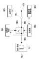
도 1은 본 발명의 실시예에 따른 보청기-호환 휴대 무선 단말기의 구성을 나타내는 개략도이다.1 is a schematic diagram showing the configuration of a hearing aid-compatible portable wireless terminal according to an embodiment of the present invention.
도 1을 참조하면, 휴대 무선 단말기(100)는 RF모듈(110, RF module), 데이터처리부(120, data processing unit), 송화부(130, transmitter), 수화부(135, receiver), 키패드(140, keypad), 표시부(145, display unit), 제어부(150, control unit), 메모리(160, memory)를 포함한다. 또한, 휴대 무선 단말기(100)는 자기코일(172, magnetic coil)을 구비하는 진동모터(170, vibration motor), 모터구동부(175, motor driving unit), 스위칭부(180, switching unit)를 더 포함한다.Referring to FIG. 1, the portable
RF모듈(110)은 휴대 무선 단말기(100)의 통신을 수행한다. 즉, RF모듈(110)은 송신되는 신호의 주파수 상승변환 및 증폭, 수신되는 신호의 저잡음 증폭 및 주파수 하강변환을 수행한다. RF모듈(110)은 송수신 경로를 분리하는 듀플렉서(duplexer)를 구비할 수 있다.The
데이터처리부(120)는 RF모듈(110)을 통해 송신될 신호의 부호화 및 변조, RF모듈(110)을 통해 수신된 신호의 복조 및 복호화를 수행한다. 데이터처리부(120)는 모뎀(modem) 및 코덱(codec)으로 구성될 수 있다.The
송화부(130)는 음성입력을 전기신호로 변환하여 데이터처리부(120)로 전송한다. 수화부(135)는 데이터처리부(120)로부터 음성대역의 신호를 수신하고 음성으로 변환하여 출력한다. 특히, 데이터처리부(120)로부터 출력되는 신호의 경로는 수화부(135)와 진동모터(170)의 두 방향으로 연결된다. 진동모터(170)에 대해서는 후술 한다. 본 실시예의 데이터처리부(120)와 수화부(135)는 단일회선(137, single line)으로 연결되지만, 후술하는 실시예와 같이 차동회선(differential line)으로 연결될 수도 있다.The
키패드(140)는 휴대 무선 단말기(100)의 동작을 제어하기 위한 사용자의 조작 신호를 입력받는다. 그러나 휴대 무선 단말기(100)의 입력부가 반드시 키패드(140)에 한정되는 것은 아니며, 터치패드(touchpad), 터치스크린(touchscreen), 스크롤 휠(scroll wheel), 옵티컬 조그(optical jog) 등이 추가로 장착되거나 키패드의 일부 또는 전부를 대체할 수 있다.The
표시부(145)는 휴대 무선 단말기(100)의 사용자 인터페이스(user interface)를 제공하며 각종 입출력 데이터를 표시한다. 표시부(145)는 액정표시장치(LCD)를 이용하는 것이 일반적이나, 다른 표시장치가 이용될 수도 있다.The
제어부(150)는 휴대 무선 단말기(100)의 전반적인 동작을 제어한다. 특히, 제어부(150)는 후술하는 모터구동부(175)와 스위칭부(180)의 동작을 제어한다.The
메모리(160)는 휴대 단말기(100)에서 실행되고 처리되는 각종 프로그램과 데이터를 저장한다. 메모리(160)는 휘발성 메모리와 비휘발성 메모리로 구성될 수 있다.The
진동모터(170)는 호 착신, 메시지 도착 등의 알림유형이 진동모드로 설정된 경우, 전화가 걸려오거나 메시지가 도착하면 진동을 발생시킨다. 진동모터(170)는 자기코일(172)을 구비하며, 모터구동부(175)에 선택적으로 연결된다. 즉, 전화가 걸려오거나 메시지가 도착하면, 모터구동부(175)와 진동모터(170) 사이에는 연결 경로가 형성된다. 아울러, 모터구동부(175)는 제어부(150)의 제어 하에 자기코일(172)로 전류를 공급하여 진동모터(170)를 구동한다.The
특히, 자기코일(172)은 보청기-호환을 위한 자기장 발생 기능을 가진다. 구체적으로 설명하면, 진동모터(170)는 데이터처리부(120)에도 선택적으로 연결되며, RF모듈(110)을 통해 수신된 신호가 데이터처리부(120)에서 복조 및 복호화를 거친 후 수화부(135)로 전송됨과 동시에 진동모터(170)로도 제공된다. 진동모터(170)로 입력된 전기신호는 자기코일(172)에 전달되어 자기신호로 바뀐다. 이 자기신호는 청각보조기(도시되지 않음) 내의 유도코일로 제공되어 음성신호로 출력된다.In particular, the
미국 연방통신위원회(FCC)의 보청기-호환 규정인 T3 규격에 따른 자기장의 세기가 도 2a 및 도 2b에 도시되어 있다. 도 2a는 1kHz에서의 자기장의 세기가 -15dB(A/m) 이하일 경우, 음성대역의 주파수별 자기장의 세기를 나타낸다. 또한, 도 2b는 1kHz에서의 자기장의 세기가 -15dB(A/m) 초과일 경우의 주파수별 자기장의 세기를 나타낸다.The strength of the magnetic field according to the T3 standard, the Hearing Aid-Compliant Regulation of the Federal Communications Commission (FCC), is shown in FIGS. 2A and 2B. FIG. 2A shows the intensity of the magnetic field for each frequency of a voice band when the strength of the magnetic field at 1 kHz is -15 dB (A / m) or less. 2B shows the intensity of the magnetic field for each frequency when the intensity of the magnetic field at 1 kHz is greater than -15 dB (A / m).
한편, 자기코일(172)에서 발생한 자기신호가 청각보조기 내의 유도코일로 제공되므로, 진동모터(170)는 청각보조기의 방향으로 자기장을 발생시킬 수 있는 위치에 있어야 한다. 따라서 진동모터(170)는 수화부(130)와 인접한 장소에 위치한다.On the other hand, since the magnetic signal generated from the
이상의 설명에서 알 수 있듯이, 진동모터(170)는 모터구동부(175)에 연결되어 통상의 진동 발생 기능을 수행하거나, 데이터처리부(120)에 연결되어 자기장 발생 기능을 수행한다. 진동모터(170)에 연결된 두 경로 중에서 하나를 선택하는 것 이 스위칭부(180)의 역할이다.As can be seen from the above description, the
스위칭부(180)는 데이터처리부(120) 쪽에 위치한 제1 접점(180a), 모터구동부(175) 쪽에 위치한 제2 접점(180b), 진동모터(170) 쪽에 위치한 제3 접점(180c)으로 구성된다. 스위칭부(180)의 제3 접점(180c)은 데이터처리부(120)와 진동모터(170) 사이의 연결 경로를 제공하기 위하여 제1 접점(180a)과 연결되거나, 모터구동부(175)와 진동모터(170) 사이의 연결 경로를 제공하기 위하여 제2 접점(180b)과 연결된다. 스위칭부(180)는 예컨대 SPDT(single pole dual throw) 스위치 또는 MEMS(micro-electro mechanical system) 스위치로 형성할 수 있다.The
이러한 스위칭부(180)의 동작은 제어부(150)에 의하여 제어된다. 진동모드로 설정된 상태에서 호 착신이나 메시지 도착 등의 이벤트가 발생하면, 제어부(150)는 스위칭부(180)를 제어하여 모터구동부(175)와 진동모터(170) 사이의 경로를 형성하고 모터구동부(175)를 제어하여 자기코일(172)에 전류를 공급한다. 이때 전류의 공급은 호 착신이 있는 동안 지속되거나 또는 메시지 도착 후 미리 설정된 시간이나 횟수만큼 이루어진다. 한편, RF모듈(110)을 통해 수신된 신호가 데이터처리부(120)를 거쳐 입력되면, 제어부(150)는 스위칭부(180)를 제어하여 데이터처리부(120)와 진동모터(170) 사이의 경로를 형성한다.The operation of the
본 실시예의 휴대 무선 단말기(100)는 증폭기(190, amplifier)를 더 포함할 수 있다. 증폭기(190)는 데이터처리부(120)에서 진동모터(170)로 전송되는 신호를 증폭한다. 데이터처리부(120)에서 출력되는 신호가 자기코일(172)에서 보청기-호환 규정을 만족할 만큼의 자기장을 발생시키기에 충분하지 않을 경우, 증폭기(190)를 이용하여 신호를 증폭시킬 수 있다.The
한편, 모터구동부(175)에서 자기코일(172)에 전류를 공급하여 진동모터(170)를 구동할 때의 전압은 약 3.1~3.3V이다. 이에 비하여, 데이터처리부(120)의 신호가 자기코일(172)로 전달될 때의 전압은 대략 1~2V에 불과하다. 이 전압은 진동모터(170)를 구동하기에 충분하지 않으므로, 데이터처리부(120)의 신호가 전달되더라도 자기코일(172)은 자기장을 발생시킬 뿐 진동모터(170)를 구동하지는 않는다.On the other hand, when the
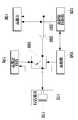
도 3은 본 발명의 다른 실시예에 따른 보청기-호환 휴대 무선 단말기의 주요 구성을 나타내는 개략도이다.3 is a schematic diagram showing a main configuration of a hearing aid-compatible portable wireless terminal according to another embodiment of the present invention.
도 3에 도시된 바와 같이, 데이터처리부(120)와 진동모터(170) 사이의 경로에는 하나 이상의 저항(192, 195)이 연결될 수 있다. 저항(192, 195) 외에도 커패시터, 인덕터와 같은 수동소자들이 적절히 선택되어 사용될 수 있다. 데이터처리부(120)와 진동모터(170) 사이의 경로에 수동소자를 연결하는 이유는 임피던스 매칭(impedance matching), 주파수 튜닝(frequency tuning) 등을 위해서이며, 이때 수동소자의 종류, 개수, 연결위치 등은 본 발명이 속하는 기술 분야에서 통상의 지식을 가진 자라면 적절히 선택할 수 있는 사항이다.As shown in FIG. 3, one or
수동소자의 예로 제시된 저항(192, 195)을 제외하면, 나머지 구성요소 및 그 동작은 전술한 실시예의 경우와 동일하다. 따라서 중복 설명은 생략한다.Except for the
도 4는 본 발명의 또 다른 실시예에 따른 보청기-호환 휴대 무선 단말기의 주요 구성을 나타내는 개략도이다.4 is a schematic diagram showing a main configuration of a hearing aid-compatible portable wireless terminal according to another embodiment of the present invention.
전술한 실시예들은 데이터처리부(120)와 수화부(130) 사이가 단일회선으로 연결된 경우이다. 이에 반하여, 본 실시예의 데이터처리부(120)와 수화부(130)는 차동회선(237)으로 연결된다. 잘 알려진 바와 같이, 차동회선(237)은 신호간의 간섭이나 잡음에 의한 영향을 최소화하기 위하여 2개의 신호 전송선으로 구성되며, 각 신호 전송선의 신호 극성을 반대로 하여 신호를 전송한다. 본 실시예의 경우, 차동회선을 채용함에 따라 증폭기는 차동증폭기(290)가 이용되며, 데이터처리부(120)와 진동모터(170) 사이의 경로에는 하나 이상의 수동소자가 연결될 수 있다.In the above-described embodiments, the
본 실시예의 나머지 구성요소 및 그 동작은 전술한 실시예의 경우와 동일하므로 중복 설명을 생략한다.The remaining components of the present embodiment and the operation thereof are the same as those of the above-described embodiment, and thus redundant description thereof will be omitted.
지금까지 실시예들을 통하여 본 발명에 따른 진동모터의 자기코일을 이용한 보청기-호환 휴대 무선 단말기에 대하여 설명하였다. 본 명세서와 도면에는 본 발명의 바람직한 실시예에 대하여 개시하였으며, 비록 특정 용어들이 사용되었으나, 이는 단지 본 발명의 기술 내용을 쉽게 설명하고 발명의 이해를 돕기 위한 일반적인 의미에서 사용된 것이지, 본 발명의 범위를 한정하고자 하는 것은 아니다. 여기에 개시된 실시예 외에도 본 발명의 기술적 사상에 바탕을 둔 다른 변형예들이 실시 가능하다는 것은 본 발명이 속하는 기술 분야에서 통상의 지식을 가진 자에게 자명한 것이다.So far, a description has been given of a hearing aid-compatible portable wireless terminal using a magnetic coil of a vibration motor according to the present invention. In the present specification and drawings, preferred embodiments of the present invention have been disclosed, and although specific terms have been used, these are merely used in a general sense to easily explain the technical contents of the present invention and to help the understanding of the present invention. It is not intended to limit the scope. It is to be understood by those skilled in the art that other modifications based on the technical idea of the present invention are possible in addition to the embodiments disclosed herein.
본 발명에 따른 휴대 무선 단말기는 기존에 이미 갖추어져 있는 진동모터의 자기코일을 이용하여 보청기-호환을 위한 자기장을 발생시키며, 이때의 자기장의 세기는 미국 연방통신위원회의 T3 규격에 따른다. 따라서 본 발명의 휴대 무선 단말기는 종래처럼 단말기의 수화부 내부에 보청기-호환을 위한 텔레코일을 내장하거나 수화기 외부에 별도로 텔레코일을 장착할 필요가 없다. 그러므로 본 발명의 휴대 무선 단말기는 공간상의 제약을 극복하면서 보청기-호환성을 만족시킬 수 있다.The portable wireless terminal according to the present invention generates a magnetic field for hearing aid-compatible using a magnetic coil of a vibration motor which is already equipped, and the strength of the magnetic field is in accordance with the T3 standard of the US Federal Communications Commission. Therefore, the portable wireless terminal of the present invention does not need to have a built-in telecoil for hearing aid-compatibility inside the handset of the terminal or a separate telecoil outside the handset. Therefore, the portable wireless terminal of the present invention can satisfy hearing aid-compatibility while overcoming space limitations.
Claims (8)
Translated fromKoreanPriority Applications (4)
| Application Number | Priority Date | Filing Date | Title |
|---|---|---|---|
| KR1020060085016AKR101258214B1 (en) | 2006-09-05 | 2006-09-05 | hearing-aid compatible mobile wireless terminal using magnetic coil of vibration motor |
| EP07016025.4AEP1903755B1 (en) | 2006-09-05 | 2007-08-15 | Hearing-aid-compatible mobile wireless device using magnetic coil of vibration motor |
| US11/844,172US8195230B2 (en) | 2006-09-05 | 2007-08-23 | Hearing-aid-compatible mobile wireless device using magnetic coil of vibration motor |
| CN2007101526245ACN101166328B (en) | 2006-09-05 | 2007-08-31 | Mobile Wireless Devices with Hearing Aids Using Magnetic Coils in Vibrating Motors |
Applications Claiming Priority (1)
| Application Number | Priority Date | Filing Date | Title |
|---|---|---|---|
| KR1020060085016AKR101258214B1 (en) | 2006-09-05 | 2006-09-05 | hearing-aid compatible mobile wireless terminal using magnetic coil of vibration motor |
Publications (2)
| Publication Number | Publication Date |
|---|---|
| KR20080021881A KR20080021881A (en) | 2008-03-10 |
| KR101258214B1true KR101258214B1 (en) | 2013-04-25 |
Family
ID=39020763
Family Applications (1)
| Application Number | Title | Priority Date | Filing Date |
|---|---|---|---|
| KR1020060085016AExpired - Fee RelatedKR101258214B1 (en) | 2006-09-05 | 2006-09-05 | hearing-aid compatible mobile wireless terminal using magnetic coil of vibration motor |
Country Status (4)
| Country | Link |
|---|---|
| US (1) | US8195230B2 (en) |
| EP (1) | EP1903755B1 (en) |
| KR (1) | KR101258214B1 (en) |
| CN (1) | CN101166328B (en) |
Families Citing this family (11)
| Publication number | Priority date | Publication date | Assignee | Title |
|---|---|---|---|---|
| KR101258214B1 (en)* | 2006-09-05 | 2013-04-25 | 삼성전자주식회사 | hearing-aid compatible mobile wireless terminal using magnetic coil of vibration motor |
| EP2129088A1 (en)* | 2008-05-30 | 2009-12-02 | Oticon A/S | A hearing aid system with a low power wireless link between a hearing instrument and a telephone |
| EP2412172A1 (en)* | 2009-03-23 | 2012-02-01 | Widex A/S | Method for establishing short-range, wireless communication between a mobile phone and a hearing aid |
| US8792661B2 (en)* | 2010-01-20 | 2014-07-29 | Audiotoniq, Inc. | Hearing aids, computing devices, and methods for hearing aid profile update |
| US9602165B2 (en) | 2010-02-02 | 2017-03-21 | Nokia Technologies Oy | Apparatus and method for a display having an induction coil |
| EP2466916B1 (en) | 2010-12-17 | 2015-12-02 | BlackBerry Limited | Portable electronic device which provides hearing aid compatibility |
| US9124303B2 (en)* | 2011-10-19 | 2015-09-01 | Nokia Technologies Oy | Apparatus and method for near field communication |
| GB2516052A (en) | 2013-07-09 | 2015-01-14 | Nokia Corp | A display apparatus |
| US9491552B2 (en)* | 2013-11-08 | 2016-11-08 | Blackberry Limited | Electronic device having hearing aid compatibility |
| CN107529353B (en)* | 2016-04-21 | 2020-12-04 | 华为技术有限公司 | A hearing aid device based on a mobile terminal |
| CN109462799B (en)* | 2018-12-29 | 2021-05-25 | 维沃移动通信有限公司 | Audio electric signal conversion assembly, terminal and audio electric signal conversion method |
Citations (4)
| Publication number | Priority date | Publication date | Assignee | Title |
|---|---|---|---|---|
| US20060013423A1 (en)* | 2004-07-13 | 2006-01-19 | Wieczorek Alfred B | Method and system for selective coupling of a communication unit to a hearing enhancement device |
| KR20060057923A (en)* | 2004-11-24 | 2006-05-29 | 부전전자부품 주식회사 | Receiver for mobile terminal for hearing aid users |
| KR20060067165A (en)* | 2004-12-14 | 2006-06-19 | 삼성전자주식회사 | Magnetic field generator for the hearing impaired in portable wireless terminal |
| KR20060095425A (en)* | 2005-06-02 | 2006-08-31 | 부전전자부품 주식회사 | Micro speaker for mobile terminal for hearing aid users |
Family Cites Families (7)
| Publication number | Priority date | Publication date | Assignee | Title |
|---|---|---|---|---|
| US5842115A (en)* | 1996-01-25 | 1998-11-24 | Ericsson Inc. | Time-duplex wireless telephone with improved hearing-aid compatibility |
| KR100677108B1 (en)* | 2003-06-12 | 2007-02-01 | 삼성전자주식회사 | Information storage medium |
| CN1630316A (en)* | 2003-12-18 | 2005-06-22 | 英业达(南京)技术有限公司 | Portable telephone capable of switching to audiphone function |
| WO2006010378A1 (en)* | 2004-07-28 | 2006-02-02 | Siemens Aktiengesellschaft | A cover, a telephone, and a method for reproducing a speech or an alert signal |
| US20060133633A1 (en)* | 2004-12-17 | 2006-06-22 | Nokia Corporation | Mobile telephone with metal sensor |
| KR101258214B1 (en)* | 2006-09-05 | 2013-04-25 | 삼성전자주식회사 | hearing-aid compatible mobile wireless terminal using magnetic coil of vibration motor |
| US8364214B2 (en)* | 2006-12-14 | 2013-01-29 | Nokia Corporation | Electrically released magnet locking mechanism |
- 2006
- 2006-09-05KRKR1020060085016Apatent/KR101258214B1/ennot_activeExpired - Fee Related
- 2007
- 2007-08-15EPEP07016025.4Apatent/EP1903755B1/ennot_activeNot-in-force
- 2007-08-23USUS11/844,172patent/US8195230B2/ennot_activeExpired - Fee Related
- 2007-08-31CNCN2007101526245Apatent/CN101166328B/ennot_activeExpired - Fee Related
Patent Citations (4)
| Publication number | Priority date | Publication date | Assignee | Title |
|---|---|---|---|---|
| US20060013423A1 (en)* | 2004-07-13 | 2006-01-19 | Wieczorek Alfred B | Method and system for selective coupling of a communication unit to a hearing enhancement device |
| KR20060057923A (en)* | 2004-11-24 | 2006-05-29 | 부전전자부품 주식회사 | Receiver for mobile terminal for hearing aid users |
| KR20060067165A (en)* | 2004-12-14 | 2006-06-19 | 삼성전자주식회사 | Magnetic field generator for the hearing impaired in portable wireless terminal |
| KR20060095425A (en)* | 2005-06-02 | 2006-08-31 | 부전전자부품 주식회사 | Micro speaker for mobile terminal for hearing aid users |
Also Published As
| Publication number | Publication date |
|---|---|
| EP1903755A2 (en) | 2008-03-26 |
| EP1903755B1 (en) | 2017-12-20 |
| CN101166328B (en) | 2011-06-22 |
| US8195230B2 (en) | 2012-06-05 |
| US20080056519A1 (en) | 2008-03-06 |
| CN101166328A (en) | 2008-04-23 |
| EP1903755A3 (en) | 2010-10-27 |
| KR20080021881A (en) | 2008-03-10 |
Similar Documents
| Publication | Publication Date | Title |
|---|---|---|
| KR101258214B1 (en) | hearing-aid compatible mobile wireless terminal using magnetic coil of vibration motor | |
| EP2464143B1 (en) | Method for operating a hearing system, hearing system and audio gateway devices | |
| JP5783352B2 (en) | Conversation system, conversation system ring, mobile phone ring, ring-type mobile phone, and voice listening method | |
| JP6030479B2 (en) | Audio output device | |
| US20130052947A1 (en) | Electronic device with shared near field communications element | |
| JP2001077719A (en) | Portable telephone set capable of having antenna impedance variation compensation | |
| KR20000018204A (en) | Wireless handsfree system for cellular phone | |
| US20050244022A1 (en) | Hearing aid compatible device | |
| US20070263804A1 (en) | Telephone with ability to communicate with mobile phones | |
| CN116668922B (en) | Electronic equipment | |
| JP4616094B2 (en) | Mobile phone | |
| EP2933989B1 (en) | Wireless telephone sound interface device comprising disconnection cause estimation | |
| JP2014011710A (en) | Mobile terminal adaptor and hearing aid system using the same | |
| CN110392332B (en) | Hearing-aid compatible device, mobile terminal and method for realizing hearing-aid compatibility | |
| JP5117345B2 (en) | Hands-free system, mobile phone, hands-free device, and device program | |
| KR20010107158A (en) | Handsfree device for wrist watch type mobile phone | |
| KR20010011015A (en) | A Mobile Telephone Terminal Equipment Having Additional Radio Terminal Equipment | |
| KR100521031B1 (en) | Device the Method for switching the audio path of mobile phone with headset using function key | |
| KR200356181Y1 (en) | Compatible multi-functional earphone device for portable handheld radiotelephone and audio apparatus | |
| KR20100018380A (en) | Mobile communication device | |
| KR101910990B1 (en) | A Hearing Device Having a Structure of Supplement Relation with a Portable Smart Device | |
| JPH0714745U (en) | Car phone system | |
| JP2002344587A (en) | Cellular phone | |
| KR200243648Y1 (en) | Handsfree device for wrist watch type mobile phone | |
| KR200258275Y1 (en) | A hands-free apparatus with an interrupt-generator by setting of a portable telephone |
Legal Events
| Date | Code | Title | Description |
|---|---|---|---|
| PA0109 | Patent application | St.27 status event code:A-0-1-A10-A12-nap-PA0109 | |
| PG1501 | Laying open of application | St.27 status event code:A-1-1-Q10-Q12-nap-PG1501 | |
| A201 | Request for examination | ||
| PA0201 | Request for examination | St.27 status event code:A-1-2-D10-D11-exm-PA0201 | |
| R18-X000 | Changes to party contact information recorded | St.27 status event code:A-3-3-R10-R18-oth-X000 | |
| D13-X000 | Search requested | St.27 status event code:A-1-2-D10-D13-srh-X000 | |
| D14-X000 | Search report completed | St.27 status event code:A-1-2-D10-D14-srh-X000 | |
| E701 | Decision to grant or registration of patent right | ||
| PE0701 | Decision of registration | St.27 status event code:A-1-2-D10-D22-exm-PE0701 | |
| GRNT | Written decision to grant | ||
| PR0701 | Registration of establishment | St.27 status event code:A-2-4-F10-F11-exm-PR0701 | |
| PR1002 | Payment of registration fee | St.27 status event code:A-2-2-U10-U11-oth-PR1002 Fee payment year number:1 | |
| PG1601 | Publication of registration | St.27 status event code:A-4-4-Q10-Q13-nap-PG1601 | |
| FPAY | Annual fee payment | Payment date:20160330 Year of fee payment:4 | |
| PR1001 | Payment of annual fee | St.27 status event code:A-4-4-U10-U11-oth-PR1001 Fee payment year number:4 | |
| FPAY | Annual fee payment | Payment date:20170330 Year of fee payment:5 | |
| PR1001 | Payment of annual fee | St.27 status event code:A-4-4-U10-U11-oth-PR1001 Fee payment year number:5 | |
| LAPS | Lapse due to unpaid annual fee | ||
| PC1903 | Unpaid annual fee | St.27 status event code:A-4-4-U10-U13-oth-PC1903 Not in force date:20180420 Payment event data comment text:Termination Category : DEFAULT_OF_REGISTRATION_FEE | |
| PC1903 | Unpaid annual fee | St.27 status event code:N-4-6-H10-H13-oth-PC1903 Ip right cessation event data comment text:Termination Category : DEFAULT_OF_REGISTRATION_FEE Not in force date:20180420 |