KR101258193B1 - I/q imbalance compensation apparatus and method for direct ub-conversion system - Google Patents
I/q imbalance compensation apparatus and method for direct ub-conversion systemDownload PDFInfo
- Publication number
- KR101258193B1 KR101258193B1KR20110121980AKR20110121980AKR101258193B1KR 101258193 B1KR101258193 B1KR 101258193B1KR 20110121980 AKR20110121980 AKR 20110121980AKR 20110121980 AKR20110121980 AKR 20110121980AKR 101258193 B1KR101258193 B1KR 101258193B1
- Authority
- KR
- South Korea
- Prior art keywords
- predistortion
- imbalance
- subcarrier
- factor
- factors
- Prior art date
- Legal status (The legal status is an assumption and is not a legal conclusion. Google has not performed a legal analysis and makes no representation as to the accuracy of the status listed.)
- Active
Links
- 238000000034methodMethods0.000titleclaimsabstractdescription26
- 238000006243chemical reactionMethods0.000titledescription6
- 238000005070samplingMethods0.000claimsabstractdescription6
- 238000004364calculation methodMethods0.000claimsdescription12
- 229910052709silverInorganic materials0.000claimsdescription4
- 239000004332silverSubstances0.000claimsdescription4
- BQCADISMDOOEFD-UHFFFAOYSA-NSilverChemical compound[Ag]BQCADISMDOOEFD-UHFFFAOYSA-N0.000claims2
- 230000015556catabolic processEffects0.000abstractdescription6
- 238000006731degradation reactionMethods0.000abstractdescription6
- 238000010586diagramMethods0.000description10
- 238000004891communicationMethods0.000description3
- 230000001419dependent effectEffects0.000description2
- 230000000694effectsEffects0.000description2
- 230000006866deteriorationEffects0.000description1
- 238000005516engineering processMethods0.000description1
- 238000007429general methodMethods0.000description1
- 238000000691measurement methodMethods0.000description1
- 238000012986modificationMethods0.000description1
- 230000004048modificationEffects0.000description1
- 238000011160researchMethods0.000description1
- 238000001228spectrumMethods0.000description1
Images


Classifications
- H—ELECTRICITY
- H04—ELECTRIC COMMUNICATION TECHNIQUE
- H04L—TRANSMISSION OF DIGITAL INFORMATION, e.g. TELEGRAPHIC COMMUNICATION
- H04L27/00—Modulated-carrier systems
- H04L27/26—Systems using multi-frequency codes
- H—ELECTRICITY
- H04—ELECTRIC COMMUNICATION TECHNIQUE
- H04L—TRANSMISSION OF DIGITAL INFORMATION, e.g. TELEGRAPHIC COMMUNICATION
- H04L27/00—Modulated-carrier systems
- H04L27/32—Carrier systems characterised by combinations of two or more of the types covered by groups H04L27/02, H04L27/10, H04L27/18 or H04L27/26
- H04L27/34—Amplitude- and phase-modulated carrier systems, e.g. quadrature-amplitude modulated carrier systems
- H04L27/36—Modulator circuits; Transmitter circuits
- H04L27/362—Modulation using more than one carrier, e.g. with quadrature carriers, separately amplitude modulated
- H04L27/364—Arrangements for overcoming imperfections in the modulator, e.g. quadrature error or unbalanced I and Q levels
- H—ELECTRICITY
- H04—ELECTRIC COMMUNICATION TECHNIQUE
- H04B—TRANSMISSION
- H04B1/00—Details of transmission systems, not covered by a single one of groups H04B3/00 - H04B13/00; Details of transmission systems not characterised by the medium used for transmission
- H04B1/02—Transmitters
- H04B1/04—Circuits
- H04B1/0475—Circuits with means for limiting noise, interference or distortion
- H—ELECTRICITY
- H03—ELECTRONIC CIRCUITRY
- H03D—DEMODULATION OR TRANSFERENCE OF MODULATION FROM ONE CARRIER TO ANOTHER
- H03D7/00—Transference of modulation from one carrier to another, e.g. frequency-changing
- H—ELECTRICITY
- H04—ELECTRIC COMMUNICATION TECHNIQUE
- H04B—TRANSMISSION
- H04B1/00—Details of transmission systems, not covered by a single one of groups H04B3/00 - H04B13/00; Details of transmission systems not characterised by the medium used for transmission
- H04B1/62—Details of transmission systems, not covered by a single one of groups H04B3/00 - H04B13/00; Details of transmission systems not characterised by the medium used for transmission for providing a predistortion of the signal in the transmitter and corresponding correction in the receiver, e.g. for improving the signal/noise ratio
- H—ELECTRICITY
- H04—ELECTRIC COMMUNICATION TECHNIQUE
- H04L—TRANSMISSION OF DIGITAL INFORMATION, e.g. TELEGRAPHIC COMMUNICATION
- H04L25/00—Baseband systems
- H04L25/02—Details ; arrangements for supplying electrical power along data transmission lines
- H—ELECTRICITY
- H04—ELECTRIC COMMUNICATION TECHNIQUE
- H04L—TRANSMISSION OF DIGITAL INFORMATION, e.g. TELEGRAPHIC COMMUNICATION
- H04L27/00—Modulated-carrier systems
- H04L27/26—Systems using multi-frequency codes
- H04L27/2601—Multicarrier modulation systems
- H04L27/2626—Arrangements specific to the transmitter only
- H04L27/2627—Modulators
Landscapes
- Engineering & Computer Science (AREA)
- Computer Networks & Wireless Communication (AREA)
- Signal Processing (AREA)
- Power Engineering (AREA)
- Digital Transmission Methods That Use Modulated Carrier Waves (AREA)
- Amplifiers (AREA)
- Transmitters (AREA)
Abstract
Translated fromKorean
Description
Translated fromKorean본 발명은 다이렉트 업컨버전 시스템에서 I/Q 불균형 보상 장치 및 방법에 관한 것으로, 특히 다이렉트 업컨버전 방식을 사용하는 OFDM(A) 시스템에서 OFDM 방식의 특성을 이용하여 I/Q 타이밍 스큐, I/Q 위상 및 게인의 불균형을 효율적으로 보상함으로써 시스템의 성능 열화를 방지할 수 있도록 한 다이렉트 업컨버전 시스템에서 I/Q 불균형 보상 장치 및 방법에 관한 것이다.The present invention relates to an apparatus and method for compensating I / Q imbalance in a direct upconversion system. In particular, the present invention relates to I / Q timing skew and I / Q using characteristics of an OFDM scheme in an OFDM (A) system using a direct upconversion scheme. An apparatus and method for compensating I / Q imbalance in a direct upconversion system capable of effectively compensating for phase and gain imbalance to prevent performance degradation of the system.
다이렉트(direct) 또는 호모다인(homodyne) 업컨버전(up-conversion) 방식은 간편성과 경제성으로 인해 다종다양한 통신 시스템에서 많이 사용되는 컨버전 기술 중의 하나이다. 도 1은 종래 다이렉트 업컨버전 시스템의 개략적인 블록 구성도이다.Direct or homodyne up-conversion is one of the conversion technologies widely used in various communication systems due to its simplicity and economy. 1 is a schematic block diagram of a conventional direct upconversion system.
도 1에 도시한 바와 같이, 종래 다이렉트 업컨버전 시스템의 개략적인 동작을 살펴보면, 디지털 베이스밴드 I 신호 및 디지털 베이스밴드 Q 신호를 각각의 DAC(Digital to Analog Converter)를 거쳐서 아날로그 I/Q 신호로 변환하고, LPF(Low Pass Filter)를 사용하여 아날로그 I/Q 신호에서 고주파 성분을 제거하며, LPF를 통과한 I/Q 베이스밴드 신호를 아날로그 디바이스인 I/Q 변조기를 사용하여 RF 신호로 주파수 변조하게 된다.As shown in FIG. 1, when a schematic operation of a conventional direct upconversion system is described, a digital baseband I signal and a digital baseband Q signal are converted into analog I / Q signals through respective digital to analog converters (DACs). Low pass filter (LPF) is used to remove high frequency components from analog I / Q signals, and I / Q baseband signals that have passed through LPF are frequency modulated into RF signals using I / Q modulators, analog devices. do.
한편, I/Q 변조기는 동상(in-phase) 성분(I)과 직각위상(quadrature-phase) 성분(Q)을 갖는데, 이 둘은 정확하게 90°로 직교해야 한다. 그러나, 다이렉트 업컨버전 시스템에 따르면, 아날로그 디바이스인 I/Q 변조기의 특성으로 인해 동상 성분(I)과 직교위상 성분(Q) 간의 위상이 90°가 안 되는 위상 불균형과 동상 성분(I)과 직교위상 성분(Q) 간의 게인이 달라지는 게인 불균형이 발생되며, 이로 인해 심각한 성능 열화를 보이는 단점을 갖는다.On the other hand, the I / Q modulator has an in-phase component (I) and a quadrature-phase component (Q), both of which must be orthogonal at exactly 90 °. However, according to the direct upconversion system, due to the characteristics of the analog device I / Q modulator, the phase imbalance and orthogonal component (I) are not orthogonal in phase between the in-phase component (I) and the quadrature component (Q). A gain imbalance occurs in which the gain between the phase components Q is different, which results in a serious performance deterioration.
도 2는 동상 성분(I)과 직교위상 성분(Q) 간의 위상/게인 불균형에 의한 영향을 보인 그래프이다. 도 2에 나타낸 바와 같이, 동상 성분(I)과 직교위상 성분(Q) 간에 위상/게인 불균형이 발생하면 미러 스펙트럼(mirror spectrum) 성분에 의해 수신단에서 해당 신호를 복조할 경우 심각한 성능 열화를 겪는다. 따라서, 이러한 I/Q 위상/게인 불균형을 측정하고 보정하는 많은 기술이 연구되고 있다.2 is a graph showing the effect of phase / gain imbalance between in-phase component (I) and quadrature component (Q). As shown in FIG. 2, if a phase / gain imbalance occurs between the in-phase component I and the quadrature component Q, a severe performance degradation occurs when the signal is demodulated at the receiving end by a mirror spectrum component. Thus, many techniques for measuring and correcting such I / Q phase / gain imbalances have been studied.
그러나 최근까지도 I/Q 간의 DAC 타이밍이나 PCB 또는 케이블 길이 차이로 발생하는 I/Q 간의 지연 시간 차이에 의한 I/Q 타이밍 스큐(time skew)를 측정하고 보정하는 기술은 그다지 많이 연구되지 않고 있다. 이에 따라 최근 활발하게 사용되고 있는 WLAN, WiMAX 또는 LTE처럼 광대역을 사용하는 OFDM 통신 시스템 등에서는 이와 같은 I/Q 타이밍 스큐에 의해 시스템의 성능이 열화되게 된다.However, until recently, there has not been much research on measuring and correcting I / Q timing skew due to DAC timing between I / Q or delay time differences between I / Q caused by PCB or cable length differences. Accordingly, the performance of the system is degraded by such I / Q timing skew in an OFDM communication system using broadband such as WLAN, WiMAX, or LTE, which is being actively used recently.
이를 감안하여 종래에는 OFDM(A)(Othorgonal Frequency Division Multiplexing (Access))을 사용하는 다이렉트 업컨버전 시스템에서 사용하는 일반적인 I/Q 불균형 보상 방법은 다이렉트 업컨버전 시스템이 갖는 I/Q 불균형 인자값을 측정한 후에 송신부에서 역으로 미리 왜곡시킴으로써 다이렉트 업컨버전 시스템의 최종 출력단에서 I/Q 불균형을 제거하는 방법이 사용되고 있다. 이하 I/Q 불균형 인자인 I/Q 타이밍 스큐와 I/Q 위상 및 게인 불균형 측정 방법은 본 발명과는 다른 출원에 의해 다룰 것인바, 본 발명에서는 이러한 I/Q 타이밍 스큐와 I/Q 위상 및 게인 불균형을 알고 있다고 가정하고 설명을 진행한다.In view of this, the conventional I / Q imbalance compensation method used in the direct upconversion system using the OFDM (A) (Othorgonal Frequency Division Multiplexing (Access)) conventionally measures the I / Q imbalance factor value of the direct upconversion system. A method of eliminating the I / Q imbalance at the final output stage of the direct upconversion system by using the transmitter to reverse distortion in advance is then used. The I / Q timing skew and I / Q phase and gain imbalance measurement methods, which are the I / Q imbalance factors, will be dealt with by different applications from the present invention. In the present invention, such I / Q timing skew and I / Q phase and Suppose you know the gain imbalance and proceed with the explanation.
도 3은 종래 다이렉트 업컨버전 시스템에서 I/Q 불균형 보상 장치를 개략적인 블록 구성도이다. 도 3에 도시한 바와 같이, 종래 다이렉트 업컨버전 시스템에서 I/Q 불균형 보상 장치는 I/Q 불균형 인자를 이용하여 I/Q 위상 및 게인 불균형을 기저대역 신호의 디지털 단에서 미리(전치) 왜곡(pre-distortion)시키고 있다. 그러나 이 경우에는 전치 왜곡이 I/Q 타이밍 스큐를 고려하지 않고 이루어지기 때문에 전치 왜곡의 효율성이 떨어지는 문제점이 있었다.3 is a schematic block diagram of an I / Q imbalance compensation device in a conventional direct upconversion system. As shown in FIG. 3, in the conventional direct upconversion system, the I / Q imbalance compensator uses an I / Q imbalance factor to pre-distorte (pre) distortion the I / Q phase and gain imbalance in the digital stage of the baseband signal. pre-distortion). However, in this case, since the predistortion is performed without considering the I / Q timing skew, the efficiency of the predistortion is inferior.
도 4는 종래 다이렉트 업컨버전 시스템에서 I/Q 위상 및 게인 불균형에 더해 타이밍 스큐까지 고려하여 미리 왜곡시킨 I/Q 불균형 보상 장치를 개략적으로 보인 블록 구성도이다. 그러나 도 4의 I/Q 불균형 보상 장치 역시 시간 영역의 기저대역에서 I/Q 타이밍 스큐를 보상하기가 매우 어렵다는 단점이 있다.FIG. 4 is a block diagram schematically illustrating an I / Q imbalance compensation device which is distorted in advance in consideration of timing skew in addition to I / Q phase and gain imbalance in a direct direct conversion system. However, the I / Q imbalance compensation device of FIG. 4 also has a disadvantage in that it is very difficult to compensate the I / Q timing skew in the baseband of the time domain.
본 발명은 전술한 문제점을 해결하기 위해 안출된 것으로서, 다이렉트 업컨버전 방식을 사용하는 OFDM(A) 시스템에서 OFDM 방식의 특성을 이용하여 I/Q 타이밍 스큐, I/Q 위상 및 게인의 불균형을 효율적으로 보상함으로써 시스템의 성능 열화를 방지할 수 있도록 한 다이렉트 업컨버전 시스템에서 I/Q 불균형 보상 장치 및 방법을 제공함을 목적으로 한다.SUMMARY OF THE INVENTION The present invention has been made to solve the above-described problems, and efficiently utilizes the characteristics of the OFDM scheme in the OFDM (A) system using the direct upconversion scheme to efficiently balance the I / Q timing skew, the I / Q phase and the gain imbalance. It is an object of the present invention to provide an apparatus and method for compensating for I / Q imbalance in a direct upconversion system that can prevent performance degradation of a system by compensating for the loss.
전술한 목적을 달성하기 위한 본 발명의 일 특징에 따르면, 미리 측정된 I/Q 불균형 인자를 읽어와서 전치 왜곡 인자 A, B, C 및 D 인자를 계산하는 전치 왜곡 인자 계산부 및 각 부반송파에 해당하는 상기 전치 왜곡 인자 A, B, C 및 D에 의해 부반송파 별로 전치 왜곡을 실행하는 전치 왜곡 실행부를 포함하여 이루어지되, 상기 전치 왜곡 인자 A, B, C 및 D는According to an aspect of the present invention for achieving the above object, the pre-distortion factor calculation unit for reading the pre-measured I / Q imbalance factor to calculate the pre-distortion factors A, B, C and D correspond to each subcarrier And a predistortion execution unit for performing predistortion for each subcarrier by the predistortion factors A, B, C, and D, wherein the predistortion factors A, B, C, and D are

전술한 본 발명의 일 특징에서, 상기 다이렉트 업컨버전 시스템은 OFDM 시스템에 적용되는 것을 특징으로 한다.In one aspect of the present invention described above, the direct upconversion system is characterized in that applied to the OFDM system.
한편 상기 전치 왜곡 인자 계산부에 의해 계산된 전치 왜곡 인자를 저장하는 전치 왜곡 인자 저장부를 더 구비하고, 상기 전치 왜곡 실행부는 상기 전치 왜곡 인자 계산부에 의해 계산된 전치 왜곡 인자를 읽어들여 전치 왜곡을 실행하는 것을 특징으로 한다.Meanwhile, a predistortion factor storage unit may further include a predistortion factor storage unit configured to store the predistortion factor calculated by the predistortion factor calculation unit, and the predistortion execution unit reads the predistortion factor calculated by the predistortion factor calculation unit to perform predistortion. It is characterized by executing.
상기 전치 왜곡 실행부는 DC 부반송파를 기준으로 좌우 대칭인 부반송파별로 수행되되,The predistortion execution unit is performed for each subcarrier symmetrically based on the DC subcarrier,


본 발명의 다른 특징에 따르면, 베이스밴드 디지털 I 및 Q 신호에 대해 I/Q 불균형을 보상하기 위한 전치 왜곡을 수행하는 제 1 항 내지 제 4 항 중 어느 한 항의 I/Q 불균형 보상 장치; 상기 I/Q 불균형 보상 장치에 의해 전치 왜곡된 I/Q 신호에 대해 IFFT를 수행하는 IFFT 수행부를 구비한 베이스밴드 처리기; 상기 IFFT 처리된 아날로그 I 및 Q 신호를 디지털 데이터로 변환하는 D/A 변환기 및 상기 디지털 변환된 I 및 Q 신호를 I/Q 변조하는 I/Q 변조기를 포함하여 이루어진 다이렉트 업컨버전 시스템이 제공된다.According to another aspect of the invention, the I / Q imbalance compensation device of any one of claims 1 to 4 for performing predistortion for compensating I / Q imbalance for baseband digital I and Q signals; A baseband processor having an IFFT performer for performing IFFT on the predistorted I / Q signal by the I / Q imbalance compensation device; A direct upconversion system including a D / A converter for converting the IFFT processed analog I and Q signals into digital data and an I / Q modulator for I / Q modulating the digitally converted I and Q signals are provided.
본 발명의 또 다른 특징에 따르면, 미리 측정된 I/Q 게인 불균형 g, I/Q 위상 불균형 Φ 및 I/Q 타이밍 스큐 time_skew를 이용하여 각 부반송파 별 전치 왜곡 인자 A, B, C 및 D를 계산하는 (a) 단계; 상기 계산된 부반송파 별 전치 왜곡 인자 A, B, C 및 D에 의해 부반송파 별로 전치 왜곡을 실행하는 (b) 단계; 전치 왜곡된 I/Q 신호에 대해 IFFT를 수행하는 (c) 단계 및 상기 IFFT 처리된 아날로그 I 및 Q 신호를 디지털 데이터로 변환한 후에 I/Q 변조하는 (d) 단계를 포함하여 이루어지되, 상기 전치 왜곡 인자 A, B, C 및 D는According to another feature of the present invention, the predistortion factors A, B, C, and D for each subcarrier are calculated using previously measured I / Q gain imbalance g, I / Q phase imbalance Φ, and I / Q timing skew time_skew. (A) doing; (B) performing predistortion for each subcarrier by using the calculated subdistortion predistortion factors A, B, C, and D; (C) performing IFFT on the predistorted I / Q signal, and (d) converting the IFFT processed analog I and Q signals into digital data and then performing I / Q modulation. Predistortion factors A, B, C, and D

전술한 구성에서, 상기 (b) 단계 이전에 상기 (a) 단계에서 계산된 전치 왜곡 인자를 저장하는 단계를 더 구비하고, 상기 (b) 단계는 상기 저장된 전치 왜곡 인자를 읽어들여 수행되는 것을 특징으로 한다.In the above-described configuration, the method may further include storing the predistortion factor calculated in the step (a) before the step (b), wherein the step (b) is performed by reading the stored predistortion factor. It is done.
상기 (b) 단계는 DC 부반송파를 기준으로 좌우 대칭인 부반송파별로 수행되되,


상기 방법은 OFDM 시스템에 적용되는 것을 특징으로 한다.The method is characterized in that it is applied to an OFDM system.
본 발명의 다이렉트 업컨버전 시스템에서 I/Q 불균형 보상 장치 및 방법에 따르면, 다이렉트 업컨버전 방식을 사용하는 OFDM(A) 시스템에서 OFDM 방식의 특성을 이용하여 I/Q 타이밍 스큐, I/Q 위상 및 게인의 불균형을 효율적으로 보상함으로써 시스템의 성능 열화를 방지할 수 있다.According to the apparatus and method for compensating I / Q imbalance in the direct upconversion system of the present invention, an I / Q timing skew, I / Q phase and By effectively compensating for the gain imbalance, the performance degradation of the system can be prevented.
도 1은 종래 다이렉트 업컨버전 시스템의 개략적인 블록 구성도.
도 2는 동상 성분(I)와 직교위상 성분(Q) 간의 위상/게인 불균형에 의한 영향을 보인 그래프.
도 3은 종래 다이렉트 업컨버전 시스템에서 I/Q 불균형 보상 장치를 개략적인 블록 구성도.
도 4는 종래 다이렉트 업컨버전 시스템에서 I/Q 위상 및 게인 불균형에 더해 타이밍 스큐까지 고려하여 미리 왜곡시킨 I/Q 불균형 보상 장치를 개략적으로 보인 블록 구성도.
도 5는 본 발명의 I/Q 불균형 보상 장치를 갖는 다이렉트 업컨버전 시스템의 전체 시스템 구성도.
도 6은 도 5에서 I/Q 불균형 보상 장치의 상세 기능 블록도.
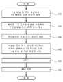
도 7은 본 발명의 다이렉트 업컨버전 시스템에서 I/Q 불균형 보상 방법을 설명하기 위한 흐름도.1 is a schematic block diagram of a conventional direct upconversion system;
2 is a graph showing the effect of phase / gain imbalance between in-phase component (I) and quadrature component (Q).
3 is a schematic block diagram of an I / Q imbalance compensation device in a conventional direct upconversion system;
4 is a block diagram schematically illustrating an I / Q imbalance compensation device that is distorted in advance in consideration of timing skew in addition to I / Q phase and gain imbalance in a conventional direct upconversion system.
5 is an overall system configuration diagram of a direct upconversion system having an I / Q imbalance compensation device of the present invention.
6 is a detailed functional block diagram of the I / Q imbalance compensation device in FIG.
7 is a flowchart illustrating a method for compensating I / Q imbalance in the direct upconversion system of the present invention.
이하에는 첨부한 도면을 참고하여 본 발명의 다이렉트 업컨버전 시스템에서 I/Q 불균형 보상 장치 및 방법의 바람직한 실시예에 대해 상세하게 설명한다.Hereinafter, with reference to the accompanying drawings will be described in detail a preferred embodiment of the I / Q imbalance compensation device and method in the direct upconversion system of the present invention.
먼저 다이렉트 업컨버전 시스템에서 측정된 I/Q 게인 불균형을 g, I/Q 위상 불균형을 Φ, I/Q 타이밍 스큐를 τ(time_skew)라고 하면, 도 3에서 전치 왜곡된 기저대역 신호는 아래의 수학식 1과 같이 나타낼 수 있다.First, if the I / Q gain imbalance measured in the direct upconversion system is g, the I / Q phase imbalance is Φ, and the I / Q timing skew is τ (time_skew), the baseband signal predistorted in FIG. It can be expressed as Equation 1.

위의 수학식 1에서


위의 수학식 2에서


한편,

도 5는 본 발명의 I/Q 불균형 보상 장치를 갖는 다이렉트 업컨버전 시스템의 전체 시스템 구성도인바. 주파수 영역에서 I/Q 불균형을 전치 왜곡시키는 구성을 나타내고 있다. 도 5에 도시한 바와 같이, 본 발명의 I/Q 불균형 보상 장치를 갖는 다이렉트 업컨버전 시스템의 전체적인 구성은 크게 베이스밴드 디지털 I 및 Q 신호에 대해 I/Q 불균형을 보상하기 위한 전치 왜곡을 수행하는 I/Q 불균형 보상 장치(110), I/Q 불균형 보상 장치(110)에서 전치 왜곡된 I/Q 신호에 대해 IFFT(Inverse Fast Fourier Transformation)을 수행하는 IFFT(120)을 구비한 베이스밴드 처리기(100), 전치 왜곡된 후에 IFFT 처리된 아날로그 I 및 Q 신호를 디지털 데이터로 변환하는 D/A 변환기(200) 및 디지털 변환된 I 및 Q 신호를 I/Q 변조기에 의해 변조하는 I/Q 변조기(300)를 포함하여 이루어진다.5 is an overall system diagram of a direct upconversion system having an I / Q imbalance compensation device of the present invention. The pre-distortion of I / Q imbalance in the frequency domain is shown. As shown in FIG. 5, the overall configuration of the direct upconversion system having the I / Q imbalance compensation device of the present invention is largely used to perform predistortion for compensating I / Q imbalance for baseband digital I and Q signals. A baseband processor having an
도 6은 도 5에서 I/Q 불균형 보상 장치의 상세 기능 블록도이다. 도 6에 도시한 바와 같이, 본 발명의 I/Q 불균형 보상 장치(110)는 IFFT 이전인 주파수 영역에서 I/Q 불균형을 미리 왜곡시키는 기능을 담당하는데, 크게 전치 왜곡 인자 계산부(112), 전치 왜곡 인자 저장부(114) 및 전치 왜곡 실행부(116)를 포함하여 이루어질 수 있다.FIG. 6 is a detailed functional block diagram of the I / Q imbalance compensation device of FIG. 5. As shown in FIG. 6, the I / Q
전술한 구성에서, 전치 왜곡 인자 계산부(112)는 미리 측정된 I/Q 불균형 인자를 읽어와서 위의 수학식 5의 A, B, C 및 D 인자를 계산하고, 이렇게 계산된 A, B, C 및 D 값을 전치 왜곡 인자 저장부(114)에 저장하는 기능을 담당한다. OFDM 방식에서 부반송파들은 고유의 주파수 값을 가지며 각 부반송파들은 주파수 상에서 부반송파 간격(subcarrier spacing)인 Δf(=샘플링 레이트/FFT 사이즈)만큼 떨어져 있다. 따라서, 위의 수학식 5에서 각 부반송파들의 주파수 성분인 ω가 서로 달라지기 때문에 각 부반송파마다 다른 A, B, C 및 D의 값을 갖는데, 이를 매번 계산하게 되면 연산량이 많아지게 된다. 따라서 본 발명에서는 다이렉트 업컨버전 시스템의 I/Q 불균형 인자인 g, Φ 및 τ(time_skew)가 하드웨어 종속적인 값으로서, 시스템의 하드웨어가 바뀌지 않는 한 고유의 g, Φ 및 τ(time_skew)의 값을 갖는 사실을 이용한다.In the above-described configuration, the
즉, 하나의 다이렉트 업컨버전 시스템이 구성되면 이 시스템은 고유의 g, Φ 및 τ(time_skew) 값을 가지므로, 전치 왜곡 인자 계산부(112)는 한번만 계산을 실행하면 되고, 계산된 A, B, C 및 D의 값을 전치 왜곡 인자 저장부(114)에 저장한다. A, B, C 및 D의 계산은 아래의 수학식 6에 의해 이루어질 수 있다.That is, when one direct up-conversion system is configured, the system has unique g, Φ, and τ (time_skew) values, and therefore, the predistortion

전치 왜곡 인자 저장부(114)는 전치 왜곡 인자 계산부(112)에서 계산된 부반송파 개수 만큼의 A, B, C 및 D값을 메모리에 저장하는 기능을 담당한다. 다음으로 전치 왜곡 실행부(116)는 전치 왜곡 인자 저장부(114)로부터 각 부반송파에 해당하는 A, B, C 및 D의 값을 읽어와서 부반송파 별로 전치 왜곡을 실행하는 기능을 한다. 주파수 영역에서 전치 왜곡은 DC 부반송파를 기준으로 좌우 대칭인 부반송파들로 이루어지는데, 전치 왜곡 수식은 아래의 수학식 7과 같이 표현할 수 있다.The predistortion

또한 위의 수학식 7에서 임의의 부반송파 인덱스 fm에 대칭인 부반송파 인덱스가 f-m이라 하면, 부반송파 fm의 전치 왜곡 베이스밴드 I/Q 신호는 아래의 수학식 8과 같이 주어질 수 있다.In addition, if the subcarrier index symmetrical to any subcarrier index fm in Equation 7 is f−m , the predistortion baseband I / Q signal of the subcarrier fm may be given by Equation 8 below.

이하에서는 본 발명의 다이렉트 업컨버전 시스템에서 I/Q 불균형 보상 방법에 대해 설명한다.Hereinafter, an I / Q imbalance compensation method in the direct upconversion system of the present invention will be described.
도 7은 본 발명의 다이렉트 업컨버전 시스템에서 I/Q 불균형 보상 방법을 설명하기 위한 흐름도이다.7 is a flowchart illustrating an I / Q imbalance compensation method in the direct upconversion system of the present invention.
먼저 다이렉트 업컨버전 통신 시스템에서 I/Q 불균형에 의한 성능 열화를 줄일 수 있는 일반적인 방법은 측정된 시스템의 I/Q 불균형을 이용하여 기저대역 신호를 미리 역으로 I/Q 불균형 왜곡시켜 최종 출력에서 I/Q 불균형이 없도록 하는 것이다.First, a general method of reducing performance degradation due to I / Q imbalance in a direct upconversion communication system is to use the measured system's I / Q imbalance to distort the baseband signal inversely by I / Q imbalance in advance. / Q to ensure there is no imbalance.
이 과정에서, I/Q 타이밍 스큐의 전치 왜곡은 시간 영역에서는 현실적으로는 매우 어렵기 때문에 OFDM 시스템에서는 OFDM 특성을 이용하여 IFFT 전단에서 I/Q 타이밍 스큐를 포함한 I/Q 불균형을 전치 왜곡시키도록 한다.In this process, the pre-distortion of the I / Q timing skew is very difficult in the time domain, so the OFDM system uses the OFDM characteristic to pre-distort the I / Q imbalance including the I / Q timing skew at the IFFT front end. .
이를 위해 먼저 단계 S10에서는 다이렉트 업컨버전 시스템에서 측정된 I/Q 게인 불균형 g, I/Q 위상 불균형 Φ 및 I/Q 타이밍 스큐 τ를 외부로부터 읽어오고, 다시 단계 S20에서는 이렇게 읽어 온 I/Q 불균형 정보를 이용하여 각 부반송파를 전치 왜곡시킬 부반송파 별 전치 왜곡 인자 A, B, C 및 D를 계산한다. 단계 S10 및 단계 S20은 I/Q 불균형 보상 장치(110)의 전치 왜곡 인자 계산부(112)에 의해 수행될 수 있다. 한편, 부반송파별 전치 왜곡 인자 A, B, C 및 D의 계산은 위의 수학식 6에 의해 수행될 수 있다.To do this, first, in step S10, the I / Q gain imbalance g, I / Q phase imbalance Φ, and I / Q timing skew τ measured by the direct upconversion system are read from the outside, and in step S20, the I / Q imbalance thus read is Calculate the predistortion factors A, B, C, and D for each subcarrier to predistort each subcarrier using the information. Steps S10 and S20 may be performed by the
한편 전치 왜곡 인자 A, B, C 및 D의 값은 부반송파 별로 다른 값을 갖기 때문에 N-점 FFT를 사용하는 OFDM 시스템의 경우, A, B, C 및 D는 각각 N개의 값을 갖는다. 이를 감안하여 단계 S30에서는 계산된 전치 왜곡 인자 A, B, C 및 D의 값을 전치 왜곡 인자 저장부(114)에 저장한다.On the other hand, since the values of the predistortion factors A, B, C, and D have different values for each subcarrier, A, B, C, and D each have N values in an OFDM system using an N-point FFT. In consideration of this, the calculated values of the predistortion factors A, B, C, and D are stored in the predistortion
한편, 다이렉트 업컨버전 시스템의 I/Q 불균형은 하드웨어 종속적인 값이므로 하나의 시스템에서는 고정된 값을 갖는다. 따라서, 전치 왜곡 인자 계산 및 저장은 시스템 초기화시 등에 한 번만 실행되면 된다.On the other hand, since the I / Q imbalance in the direct upconversion system is a hardware dependent value, it has a fixed value in one system. Therefore, the predistortion factor calculation and storage need only be performed once at the time of system initialization.
다음으로 단계 S40에서는 전치 왜곡 인자 저장부(114)로부터 각 부반송파 별 전치 왜곡 인자 A, B, C 및 D를 읽어온 후 아래의 위의 수학식 7을 이용하여 부반송파 별로 전치 왜곡을 실행, 즉 I/Q 타이밍 스큐, I/Q 위상 및 게인 불균형을 미리 보정하는데, 이 단계 S40은 전치 왜곡 실행부(116)에 의해 수행될 수 있다. 한편, 주파수 영역에서 전치 왜곡은 DC 부반송파를 기준으로 좌우 대칭인 부반송파들을 이용한다.Next, in step S40, the predistortion factors A, B, C, and D for each subcarrier are read from the predistortion
임의의 부반송파 인덱스 fm에 대칭인 부반송파 인덱스를 f-m라 하면 부반송파 fm의 전치 왜곡 베이스밴드 I/Q 신호는 위의 수학식 8에 의해 얻어질 수 있다.If the subcarrier index symmetrical to any subcarrier index fm is f−m , the predistortion baseband I / Q signal of the subcarrier fm may be obtained by Equation 8 above.
마지막으로 단계 S50 및 단계 S60에서는 전치 왜곡된 I/Q 신호가 IFFT된 후에 OFDM 신호로 변조된다.Finally, in steps S50 and S60, the predistorted I / Q signal is IFFT and then modulated into an OFDM signal.
본 발명의 다이렉트 업컨버전 시스템에서 I/Q 불균형 보상 장치 및 방법은 전술한 실시예에 국한되지 않고 본 발명의 기술 사상이 허용하는 범위 내에서 다양하게 변형하여 실시할 수가 있다.The apparatus and method for compensating I / Q imbalance in the direct upconversion system of the present invention is not limited to the above-described embodiments, and various modifications can be made within the scope of the technical idea of the present invention.
100: 베이스밴드 처리기,110: I/Q 불균형 보상 장치,
112: 전치 왜곡 인자 계산부,114: 전치 왜곡 인자 저장부,
116: 전치 왜곡 실행부,120: IFFT,
200: D/A 변환기,300: I/Q 변조기100: baseband processor, 110: I / Q imbalance compensation device,
112: predistortion factor calculation unit, 114: predistortion factor storage unit,
116: predistortion execution section, 120: IFFT,
200: D / A converter, 300: I / Q modulator
Claims (9)
Translated fromKorean미리 측정된 I/Q 불균형 인자를 읽어와서 전치 왜곡 인자 A, B, C 및 D 인자를 계산하는 전치 왜곡 인자 계산부 및
각 부반송파에 해당하는 상기 전치 왜곡 인자 A, B, C 및 D에 의해 부반송파 별로 전치 왜곡을 실행하는 전치 왜곡 실행부를 포함하여 이루어지되,
상기 전치 왜곡 인자 A, B, C 및 D는

A predistortion factor calculator for reading the premeasured I / Q imbalance factor and calculating the predistortion factors A, B, C, and D; and
A predistortion execution unit configured to perform predistortion for each subcarrier by the predistortion factors A, B, C, and D corresponding to each subcarrier,
The predistortion factors A, B, C and D are
상기 다이렉트 업컨버전 시스템은 OFDM 시스템에 적용되는 것을 특징으로 하는 다이렉트 업컨버전 시스템에서 I/Q 불균형 보상 장치.The method of claim 1,
The apparatus of claim 1, wherein the direct upconversion system is applied to an OFDM system.
상기 전치 왜곡 인자 계산부에 의해 계산된 전치 왜곡 인자를 저장하는 전치 왜곡 인자 저장부를 더 구비하고,
상기 전치 왜곡 실행부는 상기 전치 왜곡 인자 계산부에 의해 계산된 전치 왜곡 인자를 읽어들여 전치 왜곡을 실행하는 것을 특징으로 하는 다이렉트 업컨버전 시스템에서 I/Q 불균형 보상 장치.3. The method of claim 2,
A predistortion factor storage unit for storing the predistortion factor calculated by the predistortion factor calculation unit,
And the predistortion execution unit reads the predistortion factor calculated by the predistortion factor calculation unit and executes the predistortion.
상기 전치 왜곡 실행부는 DC 부반송파를 기준으로 좌우 대칭인 부반송파별로 수행되되,


The predistortion execution unit is performed for each subcarrier symmetrically based on the DC subcarrier,
상기 I/Q 불균형 보상 장치에 의해 전치 왜곡된 I/Q 신호에 대해 IFFT를 수행하는 IFFT 수행부를 구비한 베이스밴드 처리기;
상기 IFFT 처리된 아날로그 I 및 Q 신호를 디지털 데이터로 변환하는 D/A 변환기 및
상기 디지털 변환된 I 및 Q 신호를 I/Q 변조하는 I/Q 변조기를 포함하여 이루어진 다이렉트 업컨버전 시스템.The I / Q imbalance compensation device of any one of claims 1 to 4, which performs predistortion for compensating I / Q imbalance for baseband digital I and Q signals;
A baseband processor having an IFFT performer for performing IFFT on the predistorted I / Q signal by the I / Q imbalance compensation device;
A D / A converter for converting the IFFT processed analog I and Q signals into digital data;
And an I / Q modulator for I / Q modulating the digitally converted I and Q signals.
상기 계산된 부반송파 별 전치 왜곡 인자 A, B, C 및 D에 의해 부반송파 별로 전치 왜곡을 실행하는 (b) 단계;
전치 왜곡된 I/Q 신호에 대해 IFFT를 수행하는 (c) 단계 및
상기 IFFT 처리된 아날로그 I 및 Q 신호를 디지털 데이터로 변환한 후에 I/Q 변조하는 (d) 단계를 포함하여 이루어지되,
상기 전치 왜곡 인자 A, B, C 및 D는

(B) performing predistortion for each subcarrier by using the calculated subdistortion predistortion factors A, B, C, and D;
(C) performing IFFT on the predistorted I / Q signal, and
And (d) converting the IFFT processed analog I and Q signals into digital data and then performing I / Q modulation.
The predistortion factors A, B, C and D are
상기 (b) 단계 이전에 상기 (a) 단계에서 계산된 전치 왜곡 인자를 저장하는 단계를 더 구비하고,
상기 (b) 단계는 상기 저장된 전치 왜곡 인자를 읽어들여 수행되는 것을 특징으로 하는 다이렉트 업컨버전 시스템에서 I/Q 불균형 보상 방법.The method according to claim 6,
Storing the predistortion factor calculated in step (a) before step (b),
The method of claim 1, wherein the step (b) is performed by reading the stored predistortion factor.
상기 (b) 단계는 DC 부반송파를 기준으로 좌우 대칭인 부반송파별로 수행되되,


Step (b) is performed for each subcarrier symmetrically based on the DC subcarrier,
상기 방법은 OFDM 시스템에 적용되는 것을 특징으로 하는 다이렉트 업컨버전 시스템에서 I/Q 불균형 보상 방법.9. The method according to any one of claims 6 to 8,
I / Q imbalance compensation method in a direct upconversion system, characterized in that applied to the OFDM system.
Priority Applications (3)
| Application Number | Priority Date | Filing Date | Title |
|---|---|---|---|
| KR20110121980AKR101258193B1 (en) | 2011-11-22 | 2011-11-22 | I/q imbalance compensation apparatus and method for direct ub-conversion system |
| PCT/KR2012/003330WO2013077507A1 (en) | 2011-11-22 | 2012-04-30 | Apparatus and method of compensating for i/q imbalance in direct up-conversion system |
| US14/355,941US9042483B2 (en) | 2011-11-22 | 2012-04-30 | Apparatus and method of compensating for I/Q imbalance in direct up-conversion system |
Applications Claiming Priority (1)
| Application Number | Priority Date | Filing Date | Title |
|---|---|---|---|
| KR20110121980AKR101258193B1 (en) | 2011-11-22 | 2011-11-22 | I/q imbalance compensation apparatus and method for direct ub-conversion system |
Publications (1)
| Publication Number | Publication Date |
|---|---|
| KR101258193B1true KR101258193B1 (en) | 2013-04-25 |
Family
ID=48443801
Family Applications (1)
| Application Number | Title | Priority Date | Filing Date |
|---|---|---|---|
| KR20110121980AActiveKR101258193B1 (en) | 2011-11-22 | 2011-11-22 | I/q imbalance compensation apparatus and method for direct ub-conversion system |
Country Status (3)
| Country | Link |
|---|---|
| US (1) | US9042483B2 (en) |
| KR (1) | KR101258193B1 (en) |
| WO (1) | WO2013077507A1 (en) |
Families Citing this family (6)
| Publication number | Priority date | Publication date | Assignee | Title |
|---|---|---|---|---|
| US10425114B2 (en)* | 2018-01-19 | 2019-09-24 | Cox Communications, Inc. | Systems and methods for determining cable modulation using performance data |
| US10601630B1 (en)* | 2019-06-10 | 2020-03-24 | Robert Dickerman | Quadrature signal imbalance estimation |
| US12088398B1 (en) | 2020-02-29 | 2024-09-10 | Space Exploration Technologies Corp. | Configurable orthogonal frequency division multiplexing (OFDM) signal and transmitter and receiver for same |
| US11671123B1 (en) | 2020-02-29 | 2023-06-06 | Space Exploration Technologies Corp. | Digital pre-distortion compensation in a wireless communications system |
| CN111371722B (en)* | 2020-03-18 | 2021-12-31 | 南京创远信息科技有限公司 | Method for realizing predistortion compensation processing aiming at 5G NR in-band modulation signal |
| KR102819297B1 (en) | 2022-03-29 | 2025-06-12 | 한국전자통신연구원 | Iq imbalance compensation method and apparatus |
Citations (3)
| Publication number | Priority date | Publication date | Assignee | Title |
|---|---|---|---|---|
| KR20010064260A (en)* | 1999-12-27 | 2001-07-09 | 오길록 | Adaptive pre-distortion system for nonlinear distortion compensation in IMT-2000 system |
| WO2003021826A1 (en) | 2001-09-05 | 2003-03-13 | Envara Ltd. | Method for measuring and compensating gain and phase imbalances in quadrature modulators |
| KR20100124216A (en)* | 2009-05-18 | 2010-11-26 | 후지쯔 가부시끼가이샤 | Predistorter, predistortion method, and predistortion system |
Family Cites Families (4)
| Publication number | Priority date | Publication date | Assignee | Title |
|---|---|---|---|---|
| US7145962B2 (en) | 2000-08-04 | 2006-12-05 | Lg-Nortel Co., Ltd. | Predistortion digital linearizer and gain controlling method thereof |
| US7187916B2 (en)* | 2003-02-07 | 2007-03-06 | Broadcom Corporation | Method and system for measuring receiver mixer IQ mismatch |
| JP2009531924A (en)* | 2006-03-28 | 2009-09-03 | エヌエックスピー ビー ヴィ | Transmitter with delay mismatch compensation |
| US9020019B2 (en)* | 2012-02-24 | 2015-04-28 | National Instruments Corporation | Computing I/Q impairments at system output based on I/Q impairments at system input |
- 2011
- 2011-11-22KRKR20110121980Apatent/KR101258193B1/enactiveActive
- 2012
- 2012-04-30WOPCT/KR2012/003330patent/WO2013077507A1/enactiveApplication Filing
- 2012-04-30USUS14/355,941patent/US9042483B2/enactiveActive
Patent Citations (3)
| Publication number | Priority date | Publication date | Assignee | Title |
|---|---|---|---|---|
| KR20010064260A (en)* | 1999-12-27 | 2001-07-09 | 오길록 | Adaptive pre-distortion system for nonlinear distortion compensation in IMT-2000 system |
| WO2003021826A1 (en) | 2001-09-05 | 2003-03-13 | Envara Ltd. | Method for measuring and compensating gain and phase imbalances in quadrature modulators |
| KR20100124216A (en)* | 2009-05-18 | 2010-11-26 | 후지쯔 가부시끼가이샤 | Predistorter, predistortion method, and predistortion system |
Non-Patent Citations (1)
| Title |
|---|
| DRAFT(2009.03.18)* |
Also Published As
| Publication number | Publication date |
|---|---|
| US20140294057A1 (en) | 2014-10-02 |
| US9042483B2 (en) | 2015-05-26 |
| WO2013077507A1 (en) | 2013-05-30 |
Similar Documents
| Publication | Publication Date | Title |
|---|---|---|
| KR101258193B1 (en) | I/q imbalance compensation apparatus and method for direct ub-conversion system | |
| KR102318134B1 (en) | System and method for iq mismatch calibration and compensation | |
| US10305435B1 (en) | Transceivers and systems having digital distortion compensation and methods thereof | |
| KR102141257B1 (en) | Method and system for aligning signals widely spaced in frequency for wideband digital predistortion in wireless communication systems | |
| CA2714786A1 (en) | Multi-carrier amplifier linearization system and method | |
| US9143091B2 (en) | Distortion compensating apparatus, transmitter, distortion compensating method, and transfer function calculating method | |
| JP3451947B2 (en) | OFDM modulator | |
| JP2007329539A (en) | Wireless transmission apparatus and wireless transmission method | |
| CN106464631A (en) | Modulation method, apparatus, and device for orthogonal frequency division multiplexing optical signal | |
| JP6340207B2 (en) | Nonlinear distortion detector and distortion compensation power amplifier | |
| US9225577B2 (en) | Exciter and quadrature error correction method | |
| JP4958775B2 (en) | Multicarrier transmission apparatus and multicarrier transmission method | |
| JP2012095120A (en) | Measuring apparatus, measuring method, and program | |
| KR101290531B1 (en) | I/Q imbalance measurnng apparatus and method for direct ub-conversion system | |
| US8538349B2 (en) | Method and device for pre-distorting an exciter and predistortion exciter | |
| JP2003188747A (en) | Distortion compensation transmitter | |
| JP3592783B2 (en) | Transmission path equalizer | |
| Sun et al. | Optimal pilot based frequency-dependent I/Q imbalance compensation for wideband direct-conversion transmitters | |
| CN102195910B (en) | Nonlinear distortion compensation device and nonlinear distortion compensation method | |
| CN117134783B (en) | Pre-compensation method and device for transmitter signal, electronic equipment and storage medium | |
| Buchali et al. | Towards real-time CO-OFDM transceivers | |
| CN103986679A (en) | propagation time delay compensating circuit of same-phase and quadrature phase signals in OFDM receiver | |
| Fukuda et al. | Determination method for complex valued LTI transfer functions causing memory effect of power amplifier | |
| KR101097295B1 (en) | Self Estimation and Compensation scheme for IQ Imbalance of Direct Conversion Transceiver in OFDM system | |
| JP2013046261A (en) | Transmitter and transmission method |
Legal Events
| Date | Code | Title | Description |
|---|---|---|---|
| A201 | Request for examination | ||
| PA0109 | Patent application | Patent event code:PA01091R01D Comment text:Patent Application Patent event date:20111122 | |
| PA0201 | Request for examination | ||
| E902 | Notification of reason for refusal | ||
| PE0902 | Notice of grounds for rejection | Comment text:Notification of reason for refusal Patent event date:20121217 Patent event code:PE09021S01D | |
| E701 | Decision to grant or registration of patent right | ||
| PE0701 | Decision of registration | Patent event code:PE07011S01D Comment text:Decision to Grant Registration Patent event date:20130414 | |
| GRNT | Written decision to grant | ||
| PR0701 | Registration of establishment | Comment text:Registration of Establishment Patent event date:20130419 Patent event code:PR07011E01D | |
| PR1002 | Payment of registration fee | Payment date:20130422 End annual number:3 Start annual number:1 | |
| PG1601 | Publication of registration | ||
| FPAY | Annual fee payment | Payment date:20160307 Year of fee payment:4 | |
| PR1001 | Payment of annual fee | Payment date:20160307 Start annual number:4 End annual number:4 | |
| FPAY | Annual fee payment | Payment date:20170322 Year of fee payment:5 | |
| PR1001 | Payment of annual fee | Payment date:20170322 Start annual number:5 End annual number:5 | |
| FPAY | Annual fee payment | Payment date:20180409 Year of fee payment:6 | |
| PR1001 | Payment of annual fee | Payment date:20180409 Start annual number:6 End annual number:6 | |
| FPAY | Annual fee payment | Payment date:20190327 Year of fee payment:7 | |
| PR1001 | Payment of annual fee | Payment date:20190327 Start annual number:7 End annual number:7 | |
| PR1001 | Payment of annual fee | Payment date:20210310 Start annual number:9 End annual number:9 | |
| PR1001 | Payment of annual fee | Payment date:20230314 Start annual number:11 End annual number:11 |