KR101256510B1 - Apparatus for measuring luster of steel pipe - Google Patents
Apparatus for measuring luster of steel pipeDownload PDFInfo
- Publication number
- KR101256510B1 KR101256510B1KR1020090127835AKR20090127835AKR101256510B1KR 101256510 B1KR101256510 B1KR 101256510B1KR 1020090127835 AKR1020090127835 AKR 1020090127835AKR 20090127835 AKR20090127835 AKR 20090127835AKR 101256510 B1KR101256510 B1KR 101256510B1
- Authority
- KR
- South Korea
- Prior art keywords
- glossiness
- steel sheet
- measuring
- measurement module
- rotary roller
- Prior art date
- Legal status (The legal status is an assumption and is not a legal conclusion. Google has not performed a legal analysis and makes no representation as to the accuracy of the status listed.)
- Active
Links
Images


Classifications
- G—PHYSICS
- G01—MEASURING; TESTING
- G01N—INVESTIGATING OR ANALYSING MATERIALS BY DETERMINING THEIR CHEMICAL OR PHYSICAL PROPERTIES
- G01N21/00—Investigating or analysing materials by the use of optical means, i.e. using sub-millimetre waves, infrared, visible or ultraviolet light
- G01N21/17—Systems in which incident light is modified in accordance with the properties of the material investigated
- G01N21/55—Specular reflectivity
- G01N21/57—Measuring gloss
- B—PERFORMING OPERATIONS; TRANSPORTING
- B65—CONVEYING; PACKING; STORING; HANDLING THIN OR FILAMENTARY MATERIAL
- B65H—HANDLING THIN OR FILAMENTARY MATERIAL, e.g. SHEETS, WEBS, CABLES
- B65H7/00—Controlling article feeding, separating, pile-advancing, or associated apparatus, to take account of incorrect feeding, absence of articles, or presence of faulty articles
- B65H7/02—Controlling article feeding, separating, pile-advancing, or associated apparatus, to take account of incorrect feeding, absence of articles, or presence of faulty articles by feelers or detectors
- G—PHYSICS
- G01—MEASURING; TESTING
- G01B—MEASURING LENGTH, THICKNESS OR SIMILAR LINEAR DIMENSIONS; MEASURING ANGLES; MEASURING AREAS; MEASURING IRREGULARITIES OF SURFACES OR CONTOURS
- G01B11/00—Measuring arrangements characterised by the use of optical techniques
- G01B11/30—Measuring arrangements characterised by the use of optical techniques for measuring roughness or irregularity of surfaces
- G—PHYSICS
- G01—MEASURING; TESTING
- G01N—INVESTIGATING OR ANALYSING MATERIALS BY DETERMINING THEIR CHEMICAL OR PHYSICAL PROPERTIES
- G01N21/00—Investigating or analysing materials by the use of optical means, i.e. using sub-millimetre waves, infrared, visible or ultraviolet light
- G01N21/84—Systems specially adapted for particular applications
- G01N21/85—Investigating moving fluids or granular solids
Landscapes
- Physics & Mathematics (AREA)
- General Physics & Mathematics (AREA)
- Health & Medical Sciences (AREA)
- Life Sciences & Earth Sciences (AREA)
- Chemical & Material Sciences (AREA)
- Analytical Chemistry (AREA)
- Biochemistry (AREA)
- General Health & Medical Sciences (AREA)
- Immunology (AREA)
- Pathology (AREA)
- Investigating Or Analysing Materials By Optical Means (AREA)
Abstract
Translated fromKoreanDescription
Translated fromKorean본 발명은 강판의 광택도 측정장치에 관한 것으로, 보다 상세하게는 이송되는 강판과 더불어 회전되는 광택도 측정모듈 구성을 통해, 이송 중인 강판의 광택도를 연속적으로 측정할 수 있는 강판의 광택도 측정장치에 관한 것이다.The present invention relates to an apparatus for measuring the glossiness of a steel sheet, and more particularly, to measuring the glossiness of a steel sheet which can continuously measure the glossiness of the steel sheet being transported through the configuration of a rotating gloss measurement module in addition to the steel sheet being transferred. Relates to a device.
일반적으로 제품의 외관은 최종 소비자의 구매력을 자극하고 제품 경쟁력에 작용하는 중요한 요소 중 하나이다. 특히, 강판 제품에 있어서 표면 광택성은 조도 등과 함께 표면 품질을 나타내는 지수로 사용된다.In general, the appearance of the product is one of the important factors to stimulate the purchasing power of the end consumer and affect the product competitiveness. In particular, surface glossiness is used as an index indicating surface quality along with roughness in steel sheet products.
지수를 측정하는 방법의 경우, 고정된 강판에 대해서만 적용이 가능하기 때문에 특정 공정으로 이송되는 강판의 표면 품질을 측정하기 어려운 점이 있었다. 따라서, 강판의 표면 품질을 측정하기 위해, 강판의 탑(Top)부 및 테일(Tail)부에 대한 시편을 구해 강판의 조도나 광택도를 측정하는 방법이 사용되었다.In the case of measuring the index, it is difficult to measure the surface quality of the steel sheet transferred to a specific process because it is applicable only to the fixed steel sheet. Therefore, in order to measure the surface quality of the steel sheet, a method of obtaining specimens for the top portion and the tail portion of the steel sheet and measuring the roughness or glossiness of the steel sheet was used.
그런데 종래 지수를 측정하는 방법의 경우, 실제 강판의 탑(Top)부 및 테일(Tail)부는 압연이나 공정조건이 불안정한 상태이기 때문에, 강판을 대표하는 대표값으로 보기 힘들다는 문제가 있었다.By the way, in the conventional method of measuring the index, since the top portion and the tail portion of the actual steel sheet is in a state in which rolling or processing conditions are unstable, there is a problem that it is difficult to see the representative value representing the steel sheet.
이에, 강판이 이송중이더라도 강판의 표면 품질지수 중 하나인 광택도를 연 속적으로 측정하여 정확한 광택도를 얻을 수 있는 방안이 요구되고 있다.Thus, even when the steel sheet is transported, there is a need for a method for obtaining accurate glossiness by continuously measuring the glossiness, which is one of the surface quality indexes of the steel sheet.
이러한 문제점을 해결하기 위한 본 발명의 목적은, 이송 중인 강판의 광택도를 연속적으로 측정할 수 있는 강판의 광택도 측정장치를 제공하는 것이다.An object of the present invention for solving this problem is to provide an apparatus for measuring the glossiness of a steel sheet that can continuously measure the glossiness of the steel sheet being transferred.
상기 목적을 달성하기 위해 본 발명은 지지프레임, 회전롤러, 광택도 측정모듈 및 탄성커버를 포함하고, 지지프레임은 이송되는 강판의 상부측에 배치되고, 회전롤러는 지지프레임에 회전가능하게 연결되고 일면에 안착홈부가 형성되고, 광택도 측정모듈은 상기 안착홈부에 장착되어 상기 강판 표면의 광택도를 측정하며, 탄성커버는 상기 회전롤러의 외면을 감싸고 일측에 상기 안착홈부에 연통되는 측정홀부가 형성되는 것을 특징으로 한다.In order to achieve the above object, the present invention includes a support frame, a rotating roller, a glossiness measuring module and an elastic cover, the support frame is disposed on the upper side of the steel plate to be transported, and the rotating roller is rotatably connected to the support frame. A seating groove is formed on one surface, and a glossiness measuring module is mounted on the seating groove to measure the glossiness of the surface of the steel sheet, and an elastic cover surrounds the outer surface of the rotating roller and has a measuring hole connected to the seating groove on one side. It is characterized by being formed.
여기서, 상기 지지프레임에는 내부에 가이드유로가 형성되어 상하방향으로 배치되는 승강가이드가 장착되고, 상기 승강가이드에는 상기 가이드유로를 따라 슬라이딩 이동가능하게 설치되고 베어링부재를 매개로 회전롤러 회전축의 단부가 구속되는 승강편과, 상기 지지프레임과 승강편 사이를 탄성적으로 연결하는 탄성스프링이 마련되는 것이 바람직하다. 상기 회전롤러의 측부에는 푸쉬 작동에 의해 상기 광택도 측정모듈이 작동되도록 상기 광택도 측정모듈에 전기적으로 연결되는 작동버튼부가 설치되는 것이 바람직하다. 상기 작동버튼부는 상기 광택도 측정모듈보다 상기 회전롤러의 회전 전방측에 설치되어, 상기 회전롤러의 회전시 상기 승강가이드에 의해 푸쉬되면 상기 광택도 측정모듈을 일정 시간 동안 작동시키는 것이 바람 직하다.Here, the support frame is provided with a lifting guide which is formed inside the guide flow path disposed in the vertical direction, the lifting guide is installed to be slidably movable along the guide flow path and the end of the rotary roller rotary shaft through the bearing member Preferably, the restrained lifting piece and an elastic spring for elastically connecting the support frame and the lifting piece are provided. The side of the rotating roller is preferably provided with an operation button electrically connected to the glossiness measurement module to operate the glossiness measurement module by the push operation. The operation button unit is installed on the rotation front side of the rotary roller than the glossiness measurement module, it is preferable to operate the glossiness measurement module for a predetermined time when pushed by the lifting guide during the rotation of the rotary roller.
본 발명에 의하면, 특정 공정으로 강판이 이송중이더라도, 이송중인 강판에 대한 정확한 광택도를 실시간으로 측정할 수 있으므로, 공정의 효율화 및 제품에 대한 생산성 향상을 구현할 수 있다는 이점이 있다.According to the present invention, even when the steel sheet is transported in a specific process, since the accurate glossiness of the steel sheet being transported can be measured in real time, there is an advantage that the efficiency of the process and the productivity improvement for the product can be realized.
또한, 본 발명은 강판의 탑(Top)부 및 테일(Tail)부에 대한 광택도 뿐만 아니라, 강판의 전장에 대한 광택도 정보를 제공할 수 있으므로, 제품의 품질에 대한 신뢰성을 확보할 수 있다는 이점이 있다.In addition, the present invention can provide not only the glossiness of the top portion and the tail portion of the steel sheet, but also the glossiness information on the overall length of the steel sheet, thereby ensuring the reliability of the product quality. There is an advantage.
우선 각 도면의 구성요소들에 참조부호를 부가함에 있어서, 동일한 구성요소들에 대해서는 비록 다른 도면상에 표시되더라도 가능한 한 동일한 부호를 가지도록 하고 있음에 유의해야 한다. 또한, 본 발명을 설명함에 있어, 관련된 공지 구성 또는 기능에 대한 구체적인 설명이 본 발명의 요지를 흐릴 수 있다고 판단되는 경우에는 그 상세한 설명은 생략하기로 한다.In the drawings, the same reference numerals are used to designate the same or similar components throughout the drawings. In the following description of the present invention, a detailed description of known functions and configurations incorporated herein will be omitted when it may make the subject matter of the present invention rather unclear.
첨부된 도면에 의거하여 본 발명의 실시예를 상세히 설명하기로 한다.Embodiments of the present invention will be described in detail with reference to the accompanying drawings.
도 1은 본 발명에 따른 강판의 광택도 측정장치를 나타낸 도면이고, 도 2는 도 1의 "A-A"선부를 절개하여 나타낸 도면이다.1 is a view showing a glossiness measuring device of the steel sheet according to the present invention, Figure 2 is a view showing the cut portion "A-A" of FIG.
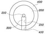
도 1 내지 도 2에 도시된 바와 같이, 본 발명에 의한 강판의 광택도 측정장치는, 지지프레임(100), 회전롤러(200), 광택도 측정모듈(300) 및 탄성커버(400)를 포함하는 구성으로, 이동되는 강판(500)의 광택도를 연속적으로 측정할 수 있다는 점에 가장 큰 특징이 있다.1 to 2, the glossiness measuring apparatus of the steel sheet according to the present invention, the
이를 구현하기 위해, 지지프레임(100)은 이동되는 강판(500)의 상면에서 회전롤러(200)가 회전될 수 있도록 한 구성으로, 강판(500)의 상측에 이격 배치되어 회전롤러(200)가 회전가능하게 연결된다.In order to implement this, the
본 실시예에서 지지프레임(100)은 강판(500)의 상측에 위치되어 회전롤러(200)가 회전가능하도록 연결되는 구성에 대하여 설명하였지만, 이 지지프레임(100)은 강판(500) 상측의 고정지점에 위치될 수 있음은 물론, 별도의 승강장치를 통해 강판(500) 상측에서 승강 가능하도록 강판(500) 상측에 위치될 수도 있다. 이 경우, 본 발명에 따른 광택도 측정장치는, 강판(500) 상에서 적절한 높이 조절이 가능하다.In this embodiment, the
지지프레임(100)은 승강가이드(110)를 통해 회전롤러(200)가 회전가능하게 연결된다. 승강가이드(110)는 지지프레임(100)의 하방향으로 연장되게 배치되는 형태로, 회전롤러(200)의 회전축(210)을 지지하는 한 쌍으로 구성된다.The
도 3은 본 발명에 따른 강판의 광택도 측정장치의 회전롤러 배면을 나타낸 도면이고, 도 4는 도 1의 "B-B"선부를 절개하여 나타낸 도면이며, 도 5는 도 1의 "C-C"선부를 절개하여 나타낸 도면이다.Figure 3 is a view showing the rear surface of the rotating roller of the glossiness measuring device of the steel sheet according to the present invention, Figure 4 is a view showing the cut "BB" line of Figure 1, Figure 5 is a "CC" line of FIG. It is a figure shown by cutting.
도 3 내지 도 5에 도시된 바와 같이, 승강가이드(110)의 내부에는 길이방향으로 길게 연장되는 가이드유로(111)가 형성되고, 가이드유로(111)에는 베어링부재(140)를 매개로 회전롤러(200)의 회전축(210)이 장착된 승강편(120)이 슬라이딩 가능하게 장착된다.As shown in FIGS. 3 to 5, the
이때, 승강편(120)은 탄성스프링(130)을 매개로 지지프레임(100)에 탄성적으로 연결되므로, 승강편(120)은 승강가이드(110)의 길이방향으로 탄성적으로 승강이 가능하다. 따라서, 회전롤러(200)와 강판(500) 간의 접촉시 회전롤러(200)에 전달되는 가압력은 승강편(120)에 전달되고, 승강편(120)은 탄성스프링(130)을 통해 회전롤러(200)에 전달된 가압력을 완충시킬 수 있다.At this time, the
회전롤러(200)는 해당 회전축(210)이 베어링부재(140)를 통해 승강편(120)에 회전가능하게 장착되어 원통형 구조로, 강판(500)과의 접촉시 강판(500)의 이동속도에 연동하여 회전될 수 있다. 이때, 회전롤러(200)의 회전속도는 강판(500)의 이동속도에 따른다.The
회전롤러(200)의 일면에는 광택도 측정모듈(300)의 장착을 위한 안착홈부(201)가 형성된다. 여기서 광택도 측정모듈(300)은 강판(500)의 광택도를 측정하기 위해 빛을 입사시키는 발광부(301) 및 반사된 빛을 측정하는 수광부(302)를 포함하여 구성되는데, 해당 구성은 강판(500)의 광택도를 측정할 수 있는 공지의 광택도 측정모듈과 동일하므로 이에 대한 자세한 설명은 생략하기로 한다.A
회전롤러(200)의 외면은 탄성커버(400)에 의해 전체적으로 감싸진다. 탄성커버(400)는 회전롤러(200)의 외면을 감싸는 고무 재질로 구성되고, 해당 일측에 안착홈부(201)에 연통되는 측정홀부(401)가 형성된다.The outer surface of the
이러한 탄성커버(400)는 광택도 측정모듈(300)을 통한 강판(500)의 광택도 측정시, 외부 빛이 광택도 측정모듈(300)에 유입되지 않도록 회전롤러(200)의 외면과 강판(500)의 접촉면을 서로 밀착시킴으로써, 광택도 측정모듈(300)을 통한 강 판(500)의 광택도 측정이 정확하게 이루어지도록 한다.The
이는 광택도 측정모듈(300)에 의해 측정된 강판(500)의 광택도는, 입사광과 반사광의 인텐시티(intensit)비를 통해 측정되기 때문은 바, 광택도 측정모듈(300)과 강판(500)이 수직되게 대향되는 지점에서 회전롤러(200)와 강판(500)이 서로 밀착되지 않으면 외부 빛이 광택도 측정모듈(300)에 유입되어 반사광의 인텐시티(intensit)비를 증가시킬 수 있다.This is because the glossiness of the
회전롤러(200)의 측부에는 광택도 측정모듈(300)에 전기적으로 연결되는 작동버튼부(150)가 설치된다. 작동버튼부(150)는 푸쉬 작동에 의해 광택도 측정모듈(300)을 일정 시간 작동되도록 하는 역할을 한다. 이 작동버튼부(150)는 광택도 측정모듈(300)보다 회전롤러(200)의 회전 전방측에 설치되므로, 회전롤러(200)의 회전시 작동버튼부(150)가 먼저 가압된 후 광택도 측정모듈(300) 위치가 가압되며, 따라서, 회전롤러(200)의 회전시 승강가이드(110)에 의해 푸쉬되면 광택도 측정모듈(300)을 일정 시간 동안 작동시킬 수 있다.On the side of the
이와 같은 구성으로 이루어진 본 발명의 작동 과정을 설명하면 다음과 같다.Hereinafter, the operation of the present invention will be described.
먼저, 회전롤러(200)와 강판(500)이 서로 대향되게 배치되도록 광택도 측정장치를 강판(500)의 상측에 적절하게 위치시킨다. 이때, 광택도 측정장치가 별도의 승강장치를 통해 높이조절이 가능하게 구성된 경우, 강판(500) 상에서 적절한 높이로 조절될 수 있다.First, the glossiness measuring device is properly positioned on the upper side of the
회전롤러(200)와 강판(500)이 서로 대향되게 배치된 상태에서 강판(500)의 이동이 이루어지면, 강판(500)의 이동에 따라 회전롤러(200)가 회전되는데, 이때, 회전롤러(200)의 탄성커버(400)와 강판(500)은 서로 밀착된 상태가 유지된다.When the movement of the
강판(500)의 이동에 따라 회전롤러(200)의 회전이 이루어지면, 광택도 측정모듈(300)보다 회전롤러(200)의 회전 전방측에 위치된 작동버튼부(150)가 승강가이드(110)에 의해 푸쉬된다.When the rotation of the
작동버튼부(150)가 푸쉬되면, 작동버튼부(150)에 전기적으로 연결된 광택도 측정모듈(300)은 일정 시간 동안 작동되므로, 광택도 측정모듈(300)이 설치된 회전롤러(200) 부분과 강판(500) 간에 접촉이 이루어지면, 광택도 측정모듈(300)을 통한 강판(500)의 광택도 측정이 정확하게 이루어질 수 있다.When the
도 6은 본 발명에 따른 강판의 광택도 측정장치에 의한 광택도 측정값을 나타낸 도면이다.6 is a view showing a glossiness measurement value by the glossiness measuring device of the steel sheet according to the present invention.
즉, 도 6에 도시되 바와 같이, 광택도 측정모듈(300)과 강판(500)이 수직되게 대향되는 지점에서 얻은 광택도 측정모듈(300)의 측정치가 강판(500)의 정확한 광택도이므로, 이 시점을 정확하게 알아야 되는 바, 이 시점을 기준으로 전,후로 광택도를 측정하여 광택도가 최소가 되는 지점을 강판(500)의 정확한 광택도라고 보면 되는 것이다.That is, as shown in Figure 6, since the measured value of the
상기에서 본 발명을 바람직한 실시 예를 사용하여 상세히 설명하였으나, 본 발명의 범위는 특정 실시 예에 한정되는 것은 아니며, 첨부된 특허청구범위에 의하여 해석되어야 할 것이다. 또한, 이 기술분야에서 통상의 지식을 습득한 자라면, 본 발명의 범위에서 벗어나지 않으면서도 많은 수정과 변형이 가능함을 이해하여야 할 것이다.Although the present invention has been described in detail using the preferred embodiments, the scope of the present invention is not limited to the specific embodiments, and should be interpreted by the appended claims. It will also be appreciated that many modifications and variations will be apparent to those skilled in the art without departing from the scope of the present invention.
도 1은 본 발명에 따른 강판의 광택도 측정장치를 도시한 구성도.1 is a block diagram showing an apparatus for measuring glossiness of a steel sheet according to the present invention.
도 2는 도 1의 "A-A"선부를 절개하여 도시한 단면도.FIG. 2 is a sectional view taken along the line “A-A” of FIG. 1; FIG.
도 3은 본 발명에 따른 강판의 광택도 측정장치의 회전롤러 배면을 도시한 배면도.Figure 3 is a rear view showing the back of the rotary roller of the glossiness measuring device of the steel sheet according to the present invention.
도 4는 도 1의 "B-B"선부를 절개하여 도시한 단면도.4 is a cross-sectional view taken along the line “B-B” of FIG. 1;
도 5는 도 1의 "C-C"선부를 절개하여 도시한 단면도.FIG. 5 is a cross-sectional view taken along line “C-C” of FIG. 1. FIG.
도 6은 본 발명에 따른 강판의 광택도 측정장치에 의한 광택도 측정값을 도시한 그래프.6 is a graph showing a glossiness measurement value by the glossiness measuring device of the steel sheet according to the present invention.
※도면의 주요 부분에 대한 부호설명※※ Refer to the explanation of the main parts of the drawing ※
100 :지지프레임 200 :회전롤러100: support frame 200: rotating roller
300 :광택도 측정모듈 400 :탄성커버300: glossiness measurement module 400: elastic cover
500 :강판500: steel sheet
Claims (4)
Translated fromKoreanPriority Applications (1)
| Application Number | Priority Date | Filing Date | Title |
|---|---|---|---|
| KR1020090127835AKR101256510B1 (en) | 2009-12-21 | 2009-12-21 | Apparatus for measuring luster of steel pipe |
Applications Claiming Priority (1)
| Application Number | Priority Date | Filing Date | Title |
|---|---|---|---|
| KR1020090127835AKR101256510B1 (en) | 2009-12-21 | 2009-12-21 | Apparatus for measuring luster of steel pipe |
Publications (2)
| Publication Number | Publication Date |
|---|---|
| KR20110071307A KR20110071307A (en) | 2011-06-29 |
| KR101256510B1true KR101256510B1 (en) | 2013-05-02 |
Family
ID=44402453
Family Applications (1)
| Application Number | Title | Priority Date | Filing Date |
|---|---|---|---|
| KR1020090127835AActiveKR101256510B1 (en) | 2009-12-21 | 2009-12-21 | Apparatus for measuring luster of steel pipe |
Country Status (1)
| Country | Link |
|---|---|
| KR (1) | KR101256510B1 (en) |
Families Citing this family (1)
| Publication number | Priority date | Publication date | Assignee | Title |
|---|---|---|---|---|
| CN103924413B (en)* | 2014-05-08 | 2015-11-18 | 连云港如年实业有限公司 | Electromagnetic induction ironing roller |
Citations (4)
| Publication number | Priority date | Publication date | Assignee | Title |
|---|---|---|---|---|
| US4053237A (en) | 1976-07-02 | 1977-10-11 | Westvaco Corporation | Measuring the surface of a roller by glossmeter |
| JP2003308520A (en) | 2003-04-09 | 2003-10-31 | Casio Comput Co Ltd | Image data reading device |
| KR100772608B1 (en) | 2006-05-29 | 2007-11-02 | 아주하이텍(주) | Auto optical inspection system |
| JP2009115532A (en) | 2007-11-05 | 2009-05-28 | Nippon Avionics Co Ltd | Pattern inspection device |
- 2009
- 2009-12-21KRKR1020090127835Apatent/KR101256510B1/enactiveActive
Patent Citations (4)
| Publication number | Priority date | Publication date | Assignee | Title |
|---|---|---|---|---|
| US4053237A (en) | 1976-07-02 | 1977-10-11 | Westvaco Corporation | Measuring the surface of a roller by glossmeter |
| JP2003308520A (en) | 2003-04-09 | 2003-10-31 | Casio Comput Co Ltd | Image data reading device |
| KR100772608B1 (en) | 2006-05-29 | 2007-11-02 | 아주하이텍(주) | Auto optical inspection system |
| JP2009115532A (en) | 2007-11-05 | 2009-05-28 | Nippon Avionics Co Ltd | Pattern inspection device |
Also Published As
| Publication number | Publication date |
|---|---|
| KR20110071307A (en) | 2011-06-29 |
Similar Documents
| Publication | Publication Date | Title |
|---|---|---|
| JP5288110B2 (en) | Angle measuring instrument | |
| CN204788225U (en) | Ceramic tile surface flatness on -line measuring device | |
| US8739427B2 (en) | Manual thickness measurement gage | |
| KR20090079420A (en) | Bending test equipment | |
| JP6283502B2 (en) | Work thickness measuring instrument | |
| CN203605900U (en) | Silicon steel sheet thickness measuring device | |
| KR101256510B1 (en) | Apparatus for measuring luster of steel pipe | |
| CN105043907B (en) | Rubber compression testing machine | |
| CN108278948B (en) | Utensil is examined to arc panel appearance for decoration | |
| CN203894046U (en) | Device for measuring non-linear characteristics of plate spring | |
| CN203798342U (en) | Special-purpose test tool for measurement | |
| CN105091813A (en) | Woodworking milling cutter cutting edge run-out detection device and detection method thereof | |
| CN106558142B (en) | A high-precision adaptive thickness detection device | |
| CN104535585A (en) | Laser diffraction measuring instrument for surface defects of bearing roller and method of laser diffraction measuring instrument | |
| CN207688857U (en) | Cell Thickness Measuring Mechanism | |
| CN107741201A (en) | A movable steel plate thickness detection mechanism | |
| JP7133212B2 (en) | Handy type sheet thickness measuring instrument | |
| CN108286928B (en) | Method for detecting overall dimension of arc-shaped plate | |
| CN207263145U (en) | An online thickness measuring device for lithium-ion battery pole pieces | |
| CN106152920A (en) | A kind of plane inspection frock | |
| CN210703904U (en) | Grooving depth detection device and grooving machine for sheet metal | |
| CN213495733U (en) | Online detection device for tortoise back with saw blade, straightening machine and online detection system for tortoise back | |
| US1984837A (en) | Measuring apparatus for rolled material | |
| CN210166301U (en) | A spectrophotometer measurement tool for measuring sheet glass | |
| CN207066350U (en) | A kind of ejecting mechanism and range measurement mechanism |
Legal Events
| Date | Code | Title | Description |
|---|---|---|---|
| PA0109 | Patent application | St.27 status event code:A-0-1-A10-A12-nap-PA0109 | |
| A201 | Request for examination | ||
| PA0201 | Request for examination | St.27 status event code:A-1-2-D10-D11-exm-PA0201 | |
| PG1501 | Laying open of application | St.27 status event code:A-1-1-Q10-Q12-nap-PG1501 | |
| D13-X000 | Search requested | St.27 status event code:A-1-2-D10-D13-srh-X000 | |
| D14-X000 | Search report completed | St.27 status event code:A-1-2-D10-D14-srh-X000 | |
| PE0902 | Notice of grounds for rejection | St.27 status event code:A-1-2-D10-D21-exm-PE0902 | |
| E13-X000 | Pre-grant limitation requested | St.27 status event code:A-2-3-E10-E13-lim-X000 | |
| P11-X000 | Amendment of application requested | St.27 status event code:A-2-2-P10-P11-nap-X000 | |
| P13-X000 | Application amended | St.27 status event code:A-2-2-P10-P13-nap-X000 | |
| E701 | Decision to grant or registration of patent right | ||
| PE0701 | Decision of registration | St.27 status event code:A-1-2-D10-D22-exm-PE0701 | |
| GRNT | Written decision to grant | ||
| PR0701 | Registration of establishment | St.27 status event code:A-2-4-F10-F11-exm-PR0701 | |
| PR1002 | Payment of registration fee | St.27 status event code:A-2-2-U10-U11-oth-PR1002 Fee payment year number:1 | |
| PG1601 | Publication of registration | St.27 status event code:A-4-4-Q10-Q13-nap-PG1601 | |
| PR1001 | Payment of annual fee | St.27 status event code:A-4-4-U10-U11-oth-PR1001 Fee payment year number:4 | |
| P22-X000 | Classification modified | St.27 status event code:A-4-4-P10-P22-nap-X000 | |
| PR1001 | Payment of annual fee | St.27 status event code:A-4-4-U10-U11-oth-PR1001 Fee payment year number:5 | |
| FPAY | Annual fee payment | Payment date:20180412 Year of fee payment:6 | |
| PR1001 | Payment of annual fee | St.27 status event code:A-4-4-U10-U11-oth-PR1001 Fee payment year number:6 | |
| R18-X000 | Changes to party contact information recorded | St.27 status event code:A-5-5-R10-R18-oth-X000 | |
| FPAY | Annual fee payment | Payment date:20190416 Year of fee payment:7 | |
| PR1001 | Payment of annual fee | St.27 status event code:A-4-4-U10-U11-oth-PR1001 Fee payment year number:7 | |
| R18-X000 | Changes to party contact information recorded | St.27 status event code:A-5-5-R10-R18-oth-X000 | |
| R18-X000 | Changes to party contact information recorded | St.27 status event code:A-5-5-R10-R18-oth-X000 | |
| PR1001 | Payment of annual fee | St.27 status event code:A-4-4-U10-U11-oth-PR1001 Fee payment year number:8 | |
| PR1001 | Payment of annual fee | St.27 status event code:A-4-4-U10-U11-oth-PR1001 Fee payment year number:9 | |
| PR1001 | Payment of annual fee | St.27 status event code:A-4-4-U10-U11-oth-PR1001 Fee payment year number:10 | |
| R18-X000 | Changes to party contact information recorded | St.27 status event code:A-5-5-R10-R18-oth-X000 | |
| PN2301 | Change of applicant | St.27 status event code:A-5-5-R10-R11-asn-PN2301 | |
| PN2301 | Change of applicant | St.27 status event code:A-5-5-R10-R14-asn-PN2301 | |
| R18-X000 | Changes to party contact information recorded | St.27 status event code:A-5-5-R10-R18-oth-X000 | |
| PR1001 | Payment of annual fee | St.27 status event code:A-4-4-U10-U11-oth-PR1001 Fee payment year number:11 | |
| R18-X000 | Changes to party contact information recorded | St.27 status event code:A-5-5-R10-R18-oth-X000 | |
| PR1001 | Payment of annual fee | St.27 status event code:A-4-4-U10-U11-oth-PR1001 Fee payment year number:12 | |
| PR1001 | Payment of annual fee | St.27 status event code:A-4-4-U10-U11-oth-PR1001 Fee payment year number:13 | |
| R18-X000 | Changes to party contact information recorded | St.27 status event code:A-5-5-R10-R18-oth-X000 |