KR101249736B1 - Textile-based magnetic field interface clothes and mobile terminal in wearable computing system - Google Patents
Textile-based magnetic field interface clothes and mobile terminal in wearable computing systemDownload PDFInfo
- Publication number
- KR101249736B1 KR101249736B1KR1020090084115AKR20090084115AKR101249736B1KR 101249736 B1KR101249736 B1KR 101249736B1KR 1020090084115 AKR1020090084115 AKR 1020090084115AKR 20090084115 AKR20090084115 AKR 20090084115AKR 101249736 B1KR101249736 B1KR 101249736B1
- Authority
- KR
- South Korea
- Prior art keywords
- coil
- magnetic field
- portable terminal
- unit
- garment
- Prior art date
- Legal status (The legal status is an assumption and is not a legal conclusion. Google has not performed a legal analysis and makes no representation as to the accuracy of the status listed.)
- Expired - Fee Related
Links
Images


Classifications
- H—ELECTRICITY
- H04—ELECTRIC COMMUNICATION TECHNIQUE
- H04B—TRANSMISSION
- H04B5/00—Near-field transmission systems, e.g. inductive or capacitive transmission systems
- H04B5/40—Near-field transmission systems, e.g. inductive or capacitive transmission systems characterised by components specially adapted for near-field transmission
- H04B5/48—Transceivers
- A—HUMAN NECESSITIES
- A41—WEARING APPAREL
- A41D—OUTERWEAR; PROTECTIVE GARMENTS; ACCESSORIES
- A41D1/00—Garments
- A41D1/002—Garments adapted to accommodate electronic equipment
- A41D1/005—Garments adapted to accommodate electronic equipment with embedded cable or connector
- H—ELECTRICITY
- H04—ELECTRIC COMMUNICATION TECHNIQUE
- H04B—TRANSMISSION
- H04B1/00—Details of transmission systems, not covered by a single one of groups H04B3/00 - H04B13/00; Details of transmission systems not characterised by the medium used for transmission
- H04B1/38—Transceivers, i.e. devices in which transmitter and receiver form a structural unit and in which at least one part is used for functions of transmitting and receiving
- H04B1/40—Circuits
- A—HUMAN NECESSITIES
- A41—WEARING APPAREL
- A41D—OUTERWEAR; PROTECTIVE GARMENTS; ACCESSORIES
- A41D27/00—Details of garments or of their making
- A41D27/20—Pockets; Making or setting-in pockets
- A41D27/205—Pockets adapted to receive a mobile phone or other electronic equipment
Landscapes
- Engineering & Computer Science (AREA)
- Textile Engineering (AREA)
- Computer Networks & Wireless Communication (AREA)
- Signal Processing (AREA)
- Outerwear In General, And Traditional Japanese Garments (AREA)
- Telephone Function (AREA)
Abstract
Translated fromKoreanDescription
Translated fromKorean본 발명은 의복형 컴퓨팅 시스템에서의 직물기반 자기장 인터페이스 의복 및 휴대 단말에 관한 것으로, 보다 상세하게는, 의복형 컴퓨팅 시스템에서 자기장을 이용하여 통신하는 직물기반 자기장 인터페이스 의복 및 휴대 단말에 관한 것이다.The present invention relates to a fabric-based magnetic field interface garment and a portable terminal in a garment computing system, and more particularly, to a fabric-based magnetic field interface garment and a portable terminal to communicate using a magnetic field in the garment computing system.
본 발명은 지식경제부 및 정보통신연구진흥원의 IT원천기술개발사업의 일환으로 수행한 연구로부터 도출된 것이다[과제관리번호:2008-F-048-02, 과제명:u-컴퓨팅 공간 협업을 위한 Wearable Personal Companion 기술 개발].The present invention is derived from a study conducted as part of the IT source technology development project of the Ministry of Knowledge Economy and the Ministry of Information and Communication Research and Development. [Task management number: 2008-F-048-02, Task name: Wearable for collaboration with u-computing space] Personal Companion Technology Development].
컴퓨팅 기술이 발전함에 따라 다양한 형태의 개인화 컴퓨팅 환경을 제공하기 위한 연구활동이 활발하게 진행되고 있다. 특히, 의복형 및 착용형 컴퓨터를 연구하는 웨어러블 컴퓨팅은 차세대 컴퓨팅 기술의 핵심분야로 거론되고 있다.With the development of computing technology, research activities are being actively conducted to provide various types of personalized computing environments. In particular, wearable computing, which studies clothing and wearable computers, has been mentioned as a core field of next-generation computing technology.
이러한 웨어러블(wearable) 컴퓨팅 분야에서 의복과 같은 시스템 내외부에 산재되어 있는 다양한 기기와의 통신수단에 필요성이 대두되어 PAN(Personal Area Network), FAN(Fabric Area Network)과 같은 연구분야로 발전하게 되었고, 다양한 방법들이 시도되어져 왔다.In the field of wearable computing, the necessity of communication means with various devices scattered inside and outside the system such as clothing has emerged, leading to the research areas such as PAN (Personal Area Network) and FAN (Fabric Area Network). Various methods have been tried.
기존 방법들은 의복에서의 연결부분을 착탈 가능한 소켓형태로 구성하여 외부기기를 연결하는 고전적인 방식과, 전파를 이용한 무선방식으로 크게 나눌 수 있다. 착탈가능한 소켓 방식은 가장 보편적으로 쓰이는 방식으로 의복 내에 내장된 소켓과 휴대 단말을 사용자가 직접 연결해야 하므로 탈부착이 불편하며, 의복을 세탁하고자 하는 경우 매번 소켓에서 휴대 단말을 분리해야하는 번거로움이 있다. 또한 의복의 소켓 커넥터부에 대한 방수처리에 주의를 기울여야하는 단점이 있다.Existing methods can be largely divided into the classical method of connecting external devices by configuring the connecting portion of the garment in the form of a detachable socket, and the wireless method using radio waves. The detachable socket method is the most commonly used method, so the user needs to directly connect the socket and the portable terminal embedded in the garment, so that the detachment is inconvenient, and when washing clothes, there is a hassle to separate the portable terminal from the socket every time. In addition, there is a drawback to pay attention to the waterproofing of the socket connector portion of the garment.
한편, 전파를 이용한 무선방식의 경우에는 RF(Radio Frequency), 지그비(Zigbee), 블루투스(Bluetooth), UWB(Ultra-wideband)와 같은 기존의 저전력 근거리 통신 방식을 이용하게 된다.On the other hand, in the case of a radio system using radio waves, conventional low-power short-range communication methods such as RF (Radio Frequency), Zigbee (Bluetooth), Bluetooth (Ultra-wideband) are used.
이러한 경우 상기한 바와 같은 근거리 무선 통신을 수행하기 위해 의복에 소정의 통신모듈이 설치되어야만 하는 것은 물론, 그 통신 모듈에 전력을 공급하기 위해 배터리와 같은 별도의 전력공급 수단이 필요하다. 또한, 전파를 이용한 무선방식의 경우 상대적으로 보안에 취약하기 때문에 신뢰성있는 통신을 보장하기 어렵다.In this case, a predetermined communication module must be installed in the garment to perform the short range wireless communication as described above, and a separate power supply means such as a battery is required to supply power to the communication module. In addition, since the radio system using radio waves is relatively vulnerable to security, it is difficult to guarantee reliable communication.
본 발명은 전술한 문제점을 해결하기 위해 도출된 것으로서,The present invention is derived to solve the above problems,
휴대 단말과 편리하게 착탈가능하고 생활 방수가 가능하며, 직조 가능하여 제작의 편리함을 제공하고 자기장 통신을 통해 뛰어난 보안성을 제공하는 직물기반 자기장 인터페이스 의복, 및 그 의복과 자기장 통신을 수행하는 휴대 단말을 제공하는 것을 목적으로 한다.A fabric-based magnetic field interface garment that can be detachably and conveniently waterproofed with a portable terminal, can be woven, provides convenience of manufacturing, and provides excellent security through magnetic field communication, and a portable terminal that performs communication with the garment. The purpose is to provide.
본 발명의 실시예에 따른 자기장 인터페이스 의복은, 휴대 단말과 비접촉식 자기장 통신을 수행하는 자기장 인터페이스 의복에 관한 것으로서, 휴대 단말이 수납되며, 상기 휴대 단말의 코일부와 대면하는 위치에서 상기 휴대 단말의 코일부와 비접촉식 자기장 통신을 수행하는 코일부가 형성된 수납부를 포함하고, 상기 수납부에 형성된 코일부는, 상기 휴대 단말의 코일부로부터 자기유도 방식을 통해 L채널 오디오 신호를 수신하는 제1오디오신호 수신코일; 및 상기 휴대 단말의 코일부로부터 자기유도 방식을 통해 R채널 오디오 신호를 수신하는 제2오디오신호 수신코일을 구비하는 것을 특징으로 한다.The magnetic field interface garment according to the embodiment of the present invention relates to a magnetic field interface garment for performing contactless magnetic field communication with a portable terminal, wherein the portable terminal is accommodated and the nose of the portable terminal is located at a position facing the coil unit of the portable terminal. A coil part including a coil part configured to perform contactless magnetic field communication with a part of the coil part, wherein the coil part includes: a first audio signal receiving coil configured to receive an L-channel audio signal from a coil part of the portable terminal through a magnetic induction method; And a second audio signal receiving coil for receiving an R channel audio signal through a magnetic induction method from the coil unit of the portable terminal.
특히, 상기 제1오디오신호 수신코일과 상기 제2오디오신호 수신코일은 서로 다른 권선방향을 갖도록 상기 수납부에 형성되어 있는 것을 특징으로 한다.In particular, the first audio signal receiving coil and the second audio signal receiving coil may be formed in the accommodating part to have different winding directions.
또한, 상기 제1오디오신호 수신코일의 권선방향과 상기 제2오디오신호 수신코일의 권선방향은 상호 직교하는 것을 특징으로 한다.The winding direction of the first audio signal receiving coil and the winding direction of the second audio signal receiving coil may be perpendicular to each other.
또한, 상기 수납부에 형성된 코일부는, 상기 제1오디오신호 수신코일 및 제2오디오신호 수신코일과 서로 다른 권선방향을 갖도록 상기 수납부에 형성되어 있는 제어신호 전송코일을 더 구비하고, 상기 제어신호 전송코일은, 상기 휴대 단말의 동작을 제어하기 위한 제어신호를 자기유도 방식을 통해 상기 휴대 단말의 자기장 센서부에 전송하는 것을 특징으로 한다.The coil unit formed in the accommodating unit may further include a control signal transmitting coil formed in the accommodating unit to have a winding direction different from that of the first audio signal receiving coil and the second audio signal receiving coil. The transmission coil is characterized by transmitting a control signal for controlling the operation of the portable terminal to the magnetic field sensor unit of the portable terminal through a magnetic induction method.
또한, 사용자로부터의 제어명령에 따라 상기 휴대 단말의 동작을 제어하기 위한 제어신호를 생성하여 상기 제어신호 전송코일에 전달하는 신호 생성부; 상기 제어신호 전송코일을 통해 교류전력을 입력받고, 입력받은 교류전력을 직류전력으로 변환하여 저장하는 AC/DC변환부; 및 상기 신호 생성부 및 상기 AC/DC변환부가 시분할(Time division) 방식으로 동작하도록 상기 신호 생성부 및 상기 AC/DC변환부의 동작을 제어하는 시각 동기부를 구비하는 것으로 특징으로 한다.In addition, the signal generation unit for generating a control signal for controlling the operation of the portable terminal according to a control command from the user and transmits to the control signal transmission coil; An AC / DC converter for receiving AC power through the control signal transmission coil and converting and storing the received AC power into DC power; And a time synchronizer for controlling the operation of the signal generator and the AC / DC converter so that the signal generator and the AC / DC converter operate in a time division manner.
또한, 상기 수납부에 형성된 코일부는, 상기 제1오디오신호 수신코일 및 제2오디오신호 수신코일과 서로 다른 권선방향을 갖도록 상기 수납부에 형성되어 있는 마이크신호 전송코일을 더 구비하고, 상기 마이크신호 전송코일은, 마이크를 통해 입력되는 마이크 신호를 자기유도 방식을 통해 상기 휴대 단말의 자기장 센서부로 전송하는 것을 특징으로 한다.The coil unit formed in the accommodating unit may further include a microphone signal transmitting coil formed in the accommodating unit to have a winding direction different from that of the first audio signal receiving coil and the second audio signal receiving coil. The transmission coil is characterized in that for transmitting the microphone signal input through the microphone to the magnetic field sensor unit of the portable terminal through a magnetic induction method.
한편, 본 발명의 다른 실시예에 따른 자기장 인터페이스 의복은, 휴대 단말과 비접촉식 자기장 통신을 수행하는 자기장 인터페이스 의복에 관한 것으로서, 휴대 단말이 수납되며, 상기 휴대 단말의 코일부와 대면하는 위치에서 상기 휴대 단말의 코일부와 비접촉식 자기장 통신을 수행하는 코일부가 형성된 수납부를 포함하고, 상기 수납부에 형성된 코일부는, 상기 휴대 단말의 동작을 제어하기 위한 제어신호를 상기 휴대 단말의 자기장 센서부에 전달하는 제어신호 전송코일을 구비하는 것을 특징으로 하는 한다.Meanwhile, the magnetic field interface garment according to another embodiment of the present invention relates to a magnetic field interface garment for performing contactless magnetic field communication with a portable terminal, wherein the portable terminal is accommodated and the portable terminal is located at a position facing the coil unit of the portable terminal. And a receiving unit having a coil unit configured to perform non-contact magnetic field communication with the coil unit of the terminal, wherein the coil unit formed in the receiving unit controls to transmit a control signal for controlling the operation of the portable terminal to the magnetic field sensor unit of the portable terminal. It characterized in that it comprises a signal transmission coil.
특히, 상기 수납부에 형성된 코일부는, 상기 제어신호 전송코일과 서로 다른 권선방향을 갖도록 상기 수납부에 형성되어 있는 전력전달신호 수신코일을 더 구비하고, 상기 전력전달신호 수신코일은 상기 휴대 단말의 코일부로부터 전력전달 신호를 수신하는 것을 특징으로 한다.In particular, the coil unit formed in the housing further comprises a power transmission signal receiving coil formed in the housing so as to have a different winding direction from the control signal transmission coil, wherein the power transmission signal receiving coil is Receiving a power transfer signal from the coil unit.
또한, 상기 제어신호 전송코일의 권선방향과 상기 전력전달신호 수신코일의 권선방향은 상호 직교하는 것을 특징으로 한다.In addition, the winding direction of the control signal transmission coil and the winding direction of the power transmission signal receiving coil is characterized in that orthogonal to each other.
한편, 본 발명의 또 다른 실시예에 따른 자기장 인터페이스 의복은, 휴대 단말과 비접촉식 자기장 통신을 수행하는 자기장 인터페이스 의복에 관한 것으로서, 휴대 단말이 수납되며, 상기 휴대 단말의 코일부와 대면하는 위치에서 상기 휴대 단말의 코일부와 비접촉식 자기장 통신을 수행하는 코일부가 형성된 수납부를 포함하고, 상기 수납부에 형성된 코일부는 제1코일 및 제2코일을 구비하고, 상기 제1코일 및 제2코일은 서로 다른 권선방향을 갖도록 상기 수납부에 형성되어 있는 것을 특징으로 한다.On the other hand, the magnetic field interface garment according to another embodiment of the present invention relates to a magnetic field interface garment for performing contactless magnetic field communication with the portable terminal, the portable terminal is accommodated, in the position facing the coil portion of the portable terminal And an accommodating part including a coil part configured to perform contactless magnetic field communication with the coil part of the portable terminal, wherein the coil part formed on the accommodating part includes a first coil and a second coil, and the first coil and the second coil have different windings. It is characterized in that formed in the housing portion to have a direction.
특히, 상기 제1코일의 권선방향과 상기 제2코일의 권선방향은 상호 직교하는 것을 특징으로 한다.In particular, the winding direction of the first coil and the winding direction of the second coil is characterized in that orthogonal to each other.
한편, 본 발명의 실시예에 따른 휴대 단말은, 자기장 인터페이스 의복에 수납되어 상기 자기장 인터페이스 의복과 비접촉식 자기장 통신을 수행하는 휴대 단말에 관한 것으로서, 자기장 인터페이스 의복의 코일부와 대면하는 위치에서 상기 자기장 인터페이스 의복의 코일부와 비접촉식 자기장 통신을 수행하는 코일부를 포 함하고, 상기 자기장 인터페이스 의복의 코일부와 비접촉식 자기장 통신을 수행하는 코일부는, 상기 자기장 인터페이스 의복의 코일부로 자기유도 방식을 통해 L채널 오디오 신호를 전송하는 제1오디오신호 전송코일; 및 상기 자기장 인터페이스 의복의 코일부로 자기유도 방식을 통해 R채널 오디오 신호를 전송하는 제2오디오신호 전송코일을 구비하는 것을 특징으로 한다.On the other hand, the portable terminal according to the embodiment of the present invention relates to a portable terminal which is housed in a magnetic field interface clothing to perform contactless magnetic field communication with the magnetic field interface clothing, the magnetic field interface at a position facing the coil part of the magnetic field interface clothing. A coil unit for performing contactless magnetic field communication with the coil unit of the garment, and the coil unit for performing contactless magnetic field communication with the coil unit of the magnetic field interface garment, L-channel audio through a magnetic induction method to the coil unit of the magnetic field interface garment. A first audio signal transmission coil for transmitting a signal; And a second audio signal transmission coil for transmitting an R-channel audio signal to the coil unit of the magnetic field interface garment through a magnetic induction method.
특히, 상기 제1오디오신호 전송코일과 상기 제2오디오신호 전송코일은 서로 다른 권선 방향을 갖도록 형성되어 있는 것을 특징으로 한다.In particular, the first audio signal transmission coil and the second audio signal transmission coil may be formed to have different winding directions.
또한, 상기 제1오디오신호 전송코일의 권선방향과 상기 제2오디오신호 전송코일의 권선방향은 상호 직교하는 것을 특징으로 한다.The winding direction of the first audio signal transmission coil and the winding direction of the second audio signal transmission coil may be perpendicular to each other.
또한, 자기유도 방식을 통해 상기 자기장 인터페이스 의복의 코일부로부터 전송되는 상기 휴대 단말의 동작을 제어하기 위한 제어신호를 수신하는 자기장 센서부를 더 구비하는 것을 특징으로 한다.The apparatus may further include a magnetic field sensor unit that receives a control signal for controlling an operation of the portable terminal transmitted from the coil unit of the magnetic field interface garment through a magnetic induction method.
또한, 상기 자기장 인터페이스 의복의 코일부와 비접촉식 자기장 통신을 수행하는 코일부는, 상기 자기장 인터페이스 의복의 코일부로 자기유도 방식을 통해 전력전달 신호를 전송하는 전력전달신호 전송코일을 더 구비하는 것을 특징으로 한다.The coil unit for performing contactless magnetic field communication with the coil unit of the magnetic field interface garment may further include a power transfer signal transmission coil for transmitting a power transfer signal to the coil unit of the magnetic field interface garment through a magnetic induction method. .
또한, 자기유도 방식을 통해 상기 자기장 인터페이스 의복의 코일부로부터 전송되는 마이크 신호를 수신하는 자기장 센서부를 더 구비하는 것을 특징으로 한다.The apparatus may further include a magnetic field sensor unit for receiving a microphone signal transmitted from the coil unit of the magnetic field interface garment through a magnetic induction method.
또한, 상기 제1오디오신호 전송코일과 상기 제2오디오신호 전송코일은 상기 휴대 단말의 외부 커넥터에 접속되는 외부 장치에 형성되어 있는 것을 특징으로 한다.The first audio signal transmission coil and the second audio signal transmission coil may be formed in an external device connected to an external connector of the portable terminal.
한편, 본 발명의 다른 실시예에 따른 휴대 단말은, 자기장 인터페이스 의복에 수납되어 상기 자기장 인터페이스 의복과 비접촉식 자기장 통신을 수행하는 휴대 단말에 관한 것으로서, 자기장 인터페이스 의복의 코일부와 대면하는 위치에서 자기유도 방식을 통해 상기 자기장 인터페이스 의복의 코일부로 전력전달 신호를 전송하는 전력전달신호 전송코일; 및 자기유도 방식을 통해 상기 자기장 인터페이스 의복의 코일부로부터 전송되는 상기 휴대 단말의 동작을 제어하기 위한 제어신호를 수신하는 자기장 센서부를 구비하는 것을 특징으로 한다.On the other hand, the portable terminal according to another embodiment of the present invention relates to a portable terminal that is accommodated in the magnetic field interface clothing to perform contactless magnetic field communication with the magnetic field interface clothing, the magnetic induction at a position facing the coil portion of the magnetic field interface clothing A power transfer signal transmission coil for transmitting a power transfer signal to the coil unit of the magnetic field interface garment through a scheme; And a magnetic field sensor unit receiving a control signal for controlling an operation of the portable terminal transmitted from the coil unit of the magnetic field interface garment through a magnetic induction method.
본 발명에 의해 다음과 같은 효과를 얻을 수 있다.According to the present invention, the following effects can be obtained.
본 발명의 의복형 컴퓨팅 시스템에서는 의복과 휴대 단말 간의 직접적인 연결없이(예를 들어, 휴대 단말을 포켓에 수납하는 형태), 의복과 휴대 단말이 통신을 수행할 수 있는 인터페이스가 가능하다.In the garment type computing system of the present invention, the interface between the garment and the portable terminal can be performed without a direct connection between the garment and the portable terminal (for example, the portable terminal is stored in a pocket).
또한, 휴대 단말이 의복에 밀착 수납되어 자기장 통신을 수행하기 때문에 신호 전달 효율이 높아 저전력 구조를 가지며, 축 배열을 달리하는 코일들간의 자기장 통신시 축 배열을 정확하게 유지하여 노이즈로 인한 신호 감쇠현상을 최소화할 수가 있다.In addition, since the mobile terminal is tightly housed in clothing and performs magnetic field communication, the signal transmission efficiency is high, and thus the low power structure is achieved. It can be minimized.
또한, 시스템에 따라 의복쪽은 전도성사로 구성된 부분만 있기 때문에 내구성이 뛰어나고, 직물로만 구성된 자연스러운 의복을 만들수 있기 때문에 의복의 디자인을 자유롭게 할 수 있다.In addition, according to the system, since the garment side has only a portion composed of conductive yarns, the durability is excellent, and a natural garment composed only of fabrics can be made, thereby freely designing the garment.
본 발명을 첨부된 도면을 참조하여 상세히 설명하면 다음과 같다. 여기서, 반복되는 설명, 본 발명의 요지를 불필요하게 흐릴 수 있는 공지 기능, 및 구성에 대한 상세한 설명은 생략한다. 본 발명의 실시형태는 당 업계에서 평균적인 지식을 가진 자에게 본 발명을 보다 완전하게 설명하기 위해서 제공되는 것이다. 따라서, 도면에서의 요소들의 형상 및 크기 등은 보다 명확한 설명을 위해 과장될 수 있다.The present invention will now be described in detail with reference to the accompanying drawings. Hereinafter, a repeated description, a known function that may obscure the gist of the present invention, and a detailed description of the configuration will be omitted. Embodiments of the present invention are provided to more fully describe the present invention to those skilled in the art. Accordingly, the shapes and sizes of the elements in the drawings and the like can be exaggerated for clarity.
이하 본 발명의 바람직한 실시예를 첨부된 도면을 참조하여 상세히 설명한다.Hereinafter, exemplary embodiments of the present invention will be described in detail with reference to the accompanying drawings.
이하의 도면에서는 휴대 단말 및 의복에 형성된 코일들을 실선으로 표시하였다. 이것은 코일들을 형상을 보다 명확하게 설명하여 본 발명의 이해를 돕기 위함일 뿐, 휴대 단말 및 의복의 외부면에 코일이 형성되어 있음을 의미하는 것은 아니다.In the following drawings, the coils formed in the mobile terminal and the garment are indicated by solid lines. This is only to help the understanding of the present invention by explaining the shape of the coils more clearly, it does not mean that the coil is formed on the outer surface of the portable terminal and clothing.
<제1실시예>≪
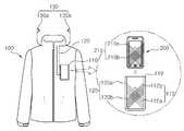
도 1은 본 발명의 제1실시예에 따른 의복형 컴퓨팅 시스템을 설명하기 위한 도면이다. 도 2는 도 1의 의복형 컴퓨팅 시스템에서의 직물기반 자기장 인터페이스 의복 및 휴대 단말의 구성을 상세하기 설명하기 위한 블록도이다.1 is a view for explaining a garment-type computing system according to a first embodiment of the present invention. FIG. 2 is a block diagram illustrating in detail a configuration of a fabric-based magnetic field interface garment and a portable terminal in the garment type computing system of FIG. 1.
본 발명의 제1실시예에 따른 의복형 컴퓨팅 시스템은 직물기반 자기장 인터페이스 의복(100, 이하 '의복') 및 휴대 단말(200)을 구비한다.The garment type computing system according to the first embodiment of the present invention includes a fabric-based magnetic field interface garment (100, hereinafter referred to as 'clothing') and a
도 1 및 도 2를 참조하면, 의복(100)에는 수납부(예컨대, 포켓)가 형성되고, 그 수납부(110)에는 사용자의 휴대 단말(200)이 수납된다. 이때, 수납부(110)는 사이즈는 휴대 단말(200)의 사이즈와 동일하거나, 휴대 단말(200)이 수납되었을 때 약간의 유격만을 갖도록 형성되는 것이 바람직하다. 이는 의복(100)과 휴대 단말(200)이 비접촉식 자기장 통신을 수행함에 있어, 자속밀도를 높여 보다 안정적으로 자기장 통신을 수행할 수가 있도록 하기 위함이다. 자기장 통신의 경우 거리 증가에 따른 신호 감쇠가 심하기 때문에 송신단과 수신단이 밀착되어 형성되는 것이 바람직한데, 본 발명에서는 휴대 단말(200)이 의복(100)에 밀착 수납되어 자기장 통신을 수행하기 때문에 신호 전달 효율이 높아 저전력 구조를 가지며, 축(Axis) 배열을 달리하는 코일들간의 자기장 통신시 축 배열을 정확하게 유지하여 노이즈로 인한 신호 감쇠현상을 최소화할 수가 있다.1 and 2, the
수납부(110)에는 휴대 단말(200)의 1차코일부(210)와 비접촉식 자기장 통신을 수행하는 2차코일부(112)가 형성된다. 비접촉식 자기장 통신은, 전류가 흐르는 도선 주위에는 자기장이 발생하고 이러한 자기장의 변화는 인접한 도선에 전류를 유도한다는 기본 원리를 이용한 무선 통신 방법으로, 본 발명에서는 의복(100)과 휴대 단말(200)의 통신을 위해 상기한 자기장 통신 방법을 이용한다.The
2차코일부(112)는 전도성사(직물형태의 도선)로 이루어진 제1코일(112a) 및 제2코일(112b)로 구성된다. 이때, 제1코일(112a) 및 제2코일(112b)는 서로 다른 축 배열을 갖도록 수납부(110)상에 형성된다. 예를 들어, 제1코일(112a)은 수납부(110)의 내부 혹은 외부면을 따라 X축 방향으로 권선되어 형성되고, 제2코일(112b)는 수납부의 내부 혹은 외부면을 따라 Y축 방향으로 권선되어 형성된다.The
2차코일부(112)는 휴대 단말(200)의 1차코일부로부터 자기 유도 방식을 통해 전송되는 오디오 신호를 수신한다.The
그리고, 2차코일부(112)는 의복(100)에 형성된 전도성사(120)를 통해 외부의 오디오 출력장치(130, 예컨대 '이어폰')와 전기적으로 연결된다. 예를 들어, 2차코일부(112)의 제1코일(112a)은 제1전도성사(120a)를 통해 오디오 출력장치(130)의 L채널(130b)과 전기적으로 연결되고, 2차코일부(112)의 제2코일(112b)은 제2전도성사(120b)를 통해 오디오 출력장치(130)의 R채널(130a)과 전기적으로 연결될 수 있다.In addition, the
여기서, 제1코일(112a)과 제2코일(112b)은 특허청구범위에 기재된 제1오디오신호 수신코일과 제2오디오신호 수신코일에 대응된다.Here, the
한편, 휴대 단말(200)은 신호 변환부(202), 저주파신호 증폭부(204), 및 1차코일부(210)를 구비한다.Meanwhile, the
신호 변환부(202)는 오디오 신호를 입력받아 1차코일부(210)에서 자기 유도방식을 통해 오디오 신호를 전송할 수 있는 형태로 변환한다.The
신호 변환부(202)에서 변환된 신호는 저주파신호 증폭부(204)에 전달되고, 저주파신호 증폭부(204)는 이를 입력받아 저주파 대역의 신호를 증폭하여 1차코일부(210)에 전달한다. 신호 변환부(202)는 흔히 말하는 이퀄라이저를 의미한다.The signal converted by the
1차코일부(210)에 전달된 신호는 자기 유도방식을 통해 의복(100)의 2차코일부(112)에 전달되고, 이렇게 전달된 신호는 의복(100)쪽에서의 별다른 회로 구성없이 오디오 출력장치(130)를 통해 출력된다. 즉, 1차코일부(210)의 제1코일(210a)에 전달된 신호는 자기 유도방식을 통해 2차코일부(112)의 제1코일(112a)에 전달되고, 1차코일부(210)의 제2코일(210b)에 전달된 신호는 자기 유도방식을 통해 2차코일부(112)의 제2코일(112b)에 전달된다.The signal transmitted to the
여기서, 제1코일(210a)과 제2코일(210b)은 특허청구범위에 기재된 제1오디오신호 전송코일과 제2오디오신호 전송코일에 각각 대응된다.Here, the
상기한 구성에 의하면, 의복(100)쪽은 전도성사로 구성된 부분만 있기 때문에 내구성이 뛰어나고, 직물로만 구성된 자연스러운 의복을 만들 수 있기 때문에 의복의 디자인을 자유롭게 할 수 있다는 장점이 있다. 특히, 세탁에 제한을 받지 않을 뿐만 아니라, 오디오 출력장치에 전력을 공급하기 위한 별도의 배터리를 구비하지 않아도 되기 때문에 세탁을 위한 배터리의 탈부착에 따른 번거로움이 없다.According to the above configuration, since the
한편, 의복(100)의 2차코일부(112)에 유도된 신호는 제1코일(112a) 및 제2코일의 재료적 특성 및 전자기 유도에 따른 주파수 특성으로 인해, 저주파 대역에서의 신호 감쇠가 나타난다(도 13 참조). 때문에 좋은 음질의 오디오 신호를 전송하기 위해서는 저주파 대역의 신호를 증폭하여 주는 것이 필요하다. 따라서, 본 발명의 저주파신호 증폭부(204)는 전송될 오디오 신호에서 저주파 대역의 신호를 증폭 하여 1차코일부(210)로 전달한다.On the other hand, the signal induced in the
<제2실시예>≪ Embodiment 2 >
도 3은 본 발명의 제2실시예에 따른 의복형 컴퓨팅 시스템을 설명하기 위한 예시도이다. 도 4는 도 3의 의복형 컴퓨팅 시스템에서의 직물기반 자기장 인터페이스 의복 및 휴대 단말의 구성을 상세하게 설명하기 위한 블록도이다.3 is an exemplary diagram for describing a garment computing system according to a second embodiment of the present invention. FIG. 4 is a block diagram for describing in detail the fabric-based magnetic field interface garment and the portable terminal of the garment type computing system of FIG. 3.
본 발명의 제2실시예에 따른 의복형 컴퓨팅 시스템은 직물기반 자기장 인터페이스 의복(300, 이하 '의복') 및 휴대 단말(350)을 구비한다.The garment type computing system according to the second embodiment of the present invention includes a fabric-based magnetic field interface garment 300 (hereinafter, 'clothing') and a
도 3 및 도 4를 참조하면, 의복(300)에는 수납부(310)가 형성되고, 그 수납부(310)에는 사용자의 휴대 단말(350)이 수납된다. 이때, 수납부(310)는 사이즈는 휴대 단말(350)의 사이즈와 동일하거나, 휴대 단말(350)이 수납되었을 때 약간의 유격만을 갖도록 형성되는 것이 바람직하다. 이는 의복(300)과 휴대 단말(350)이 비접촉식 자기장 통신을 수행함에 있어, 자속밀도를 높여 보다 안정적으로 자기장 통신을 수행할 수가 있도록 하기 위함이다.3 and 4, the
수납부(310)에는 휴대 단말(350)의 자기장 센서부(352)에 자기 유도방식을 통해 제어신호를 전달하는 제1코일(312)이 형성된다. 제1코일(312)은 1차코일부로 동작하며, 수납부(310)의 내부 혹은 외부면을 따라 권선된다.In the
여기서, 제1코일(312)은 특허청구범위에 기재된 제어신호 전송코일에 대응된다.Here, the
그리고, 의복(300)은 사용자로부터의 제어명령에 따라 휴대 단말(350)의 동 작을 제어하기 위한 제어신호를 생성하는 제어신호 생성부(340)를 구비하며, 제어신호 생성부(340)는 전도성사(330)를 통해 수납부(310)에 형성된 제1코일(312)과 전기적으로 연결된다.The
보다 상세하게는, 제어신호 생성부(340)는 제어 버튼부(342), 신호 생성부(344), 및 전원부(346)를 구비한다.In more detail, the
제어 버튼부(342)는 사용자로부터의 제어명령을 입력받기 위한 사용자 인터페이스 수단이며, 세탁 등을 고려하여 직물형태로 구성되는 것이 바람직하다.The
신호 생성부(344)는 제어 버튼부(342)를 통해 입력되는 사용자 명령에 대응하는 제어신호를 생성하여 제1코일(312)에 전달한다. 이때 신호 생성부(344)는 AM, FM, 디지털 등과 같은 모듈레이션 방법을 사용할 수 있다.The
전원부(346)는 신호 생성부(344)에서 제어신호를 생성하는데 필요한 전력을 공급하는 역할을 수행하며, 일반적으로 배터리와 같은 전력공급수단이 적용될 수 있다.The
한편, 휴대 단말(350)은 자기장 센서부(352), 신호 복원부(354), 및 단말 제어부(356)를 구비한다.Meanwhile, the
자기장 센서부(352)는 자기 유도방식을 통해 의복(300)의 제1코일(312)로부터 전달되는 제어신호를 감지하고, 감지한 제어신호를 신호 복원부(354)에 전달한다. 자기장 센서부(352)로는 제1코일(312)로부터 전달되는 제어신호를 감지하기 위한 1축 자기장 센서 또는 자기유도 가능한 코일을 사용할 수 있다.The
신호 복원부(354)는 자기장 센서부(352)에서 감지한 제어신호를 밴드패스 필터(band-pass filter) 등을 이용하여 검출한다.The
단말 제어부(356)는 신호 복원부(354)를 통해 검출된 제어신호에 근거하여 휴대 단말(350)의 동작(예컨대, 음악재생 등)을 제어한다.The
상기한 구성을 통해, 휴대폰, MP3 플레이어, PMP와 같은 휴대 단말을 커넥터와 같은 연결수단을 사용하지 않고 자기장 통신을 이용하여 제어할 수 있다.Through the above configuration, a mobile terminal such as a mobile phone, an MP3 player, or a PMP can be controlled using magnetic field communication without using a connecting means such as a connector.
<제3실시예>Third Embodiment
도 5는 본 발명의 제3실시예에 따른 의복형 컴퓨팅 시스템을 설명하기 위한 예시도이다. 도 6은 도 5의 의복형 컴퓨팅 시스템에서의 직물기반 자기장 인터페이스 의복 및 휴대 단말의 구성을 상세하게 설명하기 위한 블록도이다.5 is an exemplary diagram for describing a garment computing system according to a third embodiment of the present invention. FIG. 6 is a block diagram illustrating in detail a fabric-based magnetic field interface garment and a portable terminal in the garment type computing system of FIG. 5.
본 발명의 제3실시예에 따른 의복형 컴퓨팅 시스템은 직물기반 자기장 인터페이스 의복(400, 이하 '의복') 및 휴대 단말(450)을 구비한다.A garment type computing system according to a third embodiment of the present invention includes a fabric-based magnetic field interface garment 400 (hereinafter referred to as `` clothing '') and a
제3실시예와 제2실시예를 비교하면, 제3실시예에서의 제어신호 생성부(440)는 제2실시예에서의 제어신호 생성부(340)와는 다르게, 별도의 전력공급수단(예컨대, 도 4의 전원부)을 구비하고 있지 않다. 즉, 도 6의 제어신호 생성부(440)는 자기 유도방식을 통해 휴대 단말(400)로부터 전력을 공급받아 동작하며, 이에 대해서는 후술하는 설명을 통해 보다 상세하게 설명하기로 한다.In comparison with the third embodiment and the second embodiment, the
도 5 및 도 6을 참조하면, 의복(400)에는 수납부(예컨대, 포켓)가 형성되고, 그 수납부(410)에는 사용자의 휴대 단말(450)이 수납된다. 이때, 수납부(410)는 사 이즈는 휴대 단말(450)의 사이즈와 동일하거나, 휴대 단말(450)이 수납되었을 때 약간의 유격만을 갖도록 형성되는 것이 바람직하다. 이는 의복(400)과 휴대 단말(450)이 비접촉식 자기장 통신을 수행함에 있어, 자속밀도를 높여 보다 안정적으로 자기장 통신을 수행할 수가 있도록 하기 위함이다. 본 발명에서는 휴대 단말(450)이 의복(400)에 밀착 수납되어 자기장 통신을 수행하기 때문에 신호 전달 효율이 높아 저전력 구조를 가지며, 축(Axis) 배열을 달리하는 코일들간의 자기장 통신시 축 배열을 정확하게 유지하여 노이즈로 인한 신호 감쇠현상을 최소화할 수가 있다.5 and 6, the
수납부(410)에는 휴대 단말(450)의 1차코일부(제1코일, 456)와 비접촉식 자기장 통신을 수행하는 2차코일부(제1코일, 412)와, 제어신호 생성부(440)로부터의 제어신호를 자기 유도방식을 통해 휴대 단말(450)의 자기장 센서부(452)에 전달하는 1차코일부(제2코일, 414)가 형성된다.The
2차코일부로 동작하는 제1코일(412)과 1차코일부로 동작하는 제2코일(414)는 전도성사(직물형태의 도선)로 이루어지며, 제1코일(412) 및 제2코일(414)는 서로 다른 축 배열을 갖도록 수납부(410)상에 형성된다. 예를 들어, 제1코일(412)은 수납부(410)의 내부 혹은 외부면을 따라 X축 방향으로 권선되고, 제2코일(414)는 수납부(410)의 내부 혹은 외부면을 따라 Y축 방향으로 권선된다.The
그리고, 의복(400)은 사용자로부터의 제어명령에 따라 휴대 단말(450)의 동작을 제어하기 위한 제어신호를 생성하는 제어신호 생성부(440)를 구비하며, 제어신호 생성부(440)는 전도성사(430)를 통해 수납부(410)에 형성된 제1코일(412) 및 제2코일(414)와 전기적으로 연결된다.The
여기서, 제1코일(412)과 제2코일(414)은 특허청구범위에 기재된 전력전달신호 수신코일과 제어신호 전송코일에 각각 대응된다.Here, the
도 6을 참조하여 보다 상세하게 설명하면, 제어신호 생성부(440)는 AC/DC 변환부(416), 신호 생성부(446), 및 제어 버튼부(442)를 구비한다.Referring to FIG. 6, the
AC/DC 변환부(416)는 제1전도성사(430a)를 통해 수납부(410)의 제1코일(412)과 전기적으로 연결되고, 제1코일(412)로부터 교류전력을 입력받아 직류전력으로 변환하여 신호 생성부(446)에 공급한다.The AC /
제어 버튼부(442)는 사용자로부터의 제어명령을 입력받기 위한 사용자 인터페이스 수단이며, 직물형태로 구성된다.The
신호 생성부(446)는 제어 버튼부(442)를 통해 입력되는 사용자 명령에 대응하는 제어신호를 생성하여 수납부(410)의 제2코일(414)에 전달한다. 이때 신호 생성부(446)는 AM, FM, 디지털 등과 같은 모듈레이션 방법을 사용할 수 있다.The
한편, 휴대 단말(450)은 전원부(460), 전력전달신호 생성부(462), 제1코일(456), 단말 제어부(472), 신호 복원부(470), 및 자기장 센서부(452)를 구비한다.Meanwhile, the
전력전달신호 생성부(462)는 전원부(460)로부터 전력을 공급받아 의복(400)의 제어신호 생성부(440)에 전력을 공급하기 위한 전력전달 신호를 생성한다.The power
전력전달신호 생성부(462)에서 생성된 전력전달 신호는 제1코일(456)에 전달 되고, 제1코일(456)은 자기 유도방식을 통해 전력전달 신호를 의복(400)의 제1코일(412)로 전달한다. 여기서, 휴대 단말(450)의 제1코일(456)은 특허청구범위에 기재된 전력전달신호 전송코일에 대응된다.The power transfer signal generated by the power
자기장 센서부(452)는 자기 유도방식을 통해 의복(400)의 제2코일(414)로부터 전달되는 제어신호를 감지하고, 감지한 제어신호를 신호 복원부(470)에 전달한다. 자기장 센서부(452)로는 제2코일(414)로부터 전달되는 제어신호를 감지하기 위한 1축 자기장 센서 또는 자기유도를 할 수 있는 코일을 사용할 수 있다.The
신호 복원부(470)는 자기장 센서부(452)에서 감지한 제어신호를 밴드패스 필터 등을 이용하여 검출한다.The
단말 제어부(472)는 신호 복원부(470)를 통해 검출된 제어신호에 근거하여 휴대 단말(450)의 동작(예컨대, 음악재생 등)을 제어한다. 상기한 구성을 통해, 휴대폰, MP3 플레이어, PMP와 같은 휴대 단말을 커넥터와 같은 연결수단을 사용하지 않고 자기장 통신을 이용하여 제어할 수 있다.The
상기한 구성에 의하면, 제어신호 생성부(440)에 전력을 공급하기 위한 별도의 배터리를 구비하지 않아도 되기 때문에 세탁을 위한 배터리의 탈부착에 따른 번거로움이 없다.According to the above configuration, since it is not necessary to provide a separate battery for supplying power to the
<제4실시예><Fourth Embodiment>
도 7은 본 발명의 제4실시예에 따른 의복형 컴퓨팅 시스템을 설명하기 위한 예시도이다. 도 8은 도 7의 의복형 컴퓨팅 시스템에서의 직물기반 자기장 인터페이 스 의복 및 휴대 단말의 구성을 상세하게 설명하기 위한 블록도이다.7 is an exemplary diagram for describing a garment computing system according to a fourth embodiment of the present invention. FIG. 8 is a block diagram for explaining in detail the fabric-based magnetic field interface garment and the portable terminal of the garment-type computing system of FIG. 7.
본 발명의 제4실시예에 따른 의복형 컴퓨팅 시스템은 직물기반 자기장 인터페이스 의복(500, 이하 '의복') 및 휴대 단말(550)을 구비한다.A garment type computing system according to a fourth embodiment of the present invention includes a fabric-based magnetic field interface garment 500 (hereinafter referred to as `` clothing '') and a
도 7 및 도 8을 참조하면, 의복(500)에는 수납부(510)가 형성되고, 그 수납부(510)에는 사용자의 휴대 단말(550)이 수납된다. 이때, 수납부(510)는 사이즈는 휴대 단말(550)의 사이즈와 동일하거나, 휴대 단말(550)이 수납되었을 때 약간의 유격만을 갖도록 형성되는 것이 바람직하다. 이는 의복(500)과 휴대 단말(550)이 비접촉식 자기장 통신을 수행함에 있어, 자속밀도를 높여 보다 안정적으로 자기장 통신을 수행할 수가 있도록 하기 위함이다. 본 발명에서는 휴대 단말(550)이 의복(500)에 밀착 수납되어 자기장 통신을 수행하기 때문에 신호 전달 효율이 높아 저전력 구조를 가지며, 축(Axis) 배열을 달리하는 코일들간의 자기장 통신시 축 배열을 정확하게 유지하여 노이즈로 인한 신호 감쇠현상을 최소화할 수가 있다.7 and 8, the
수납부(510)에는 휴대 단말(550)의 1차코일부(556)와 비접촉식 자기장 통신을 수행하는 2차코일부(512)와, 휴대 단말(550)의 자기장 센서부(552)에 자기 유도방식을 통해 제어신호를 전달하는 1차코일부(제3코일, 514)가 형성된다.In the
수납부(510)의 2차코일부(512)는 전도성사(직물형태의 도선)로 이루어진 제1코일(512a) 및 제2코일(512b)로 구성된다. 이때, 제1코일(512a) 및 제2코일(512b)은 서로 다른 축 배열을 갖도록 수납부(510)상에 형성된다. 예를 들어, 제1코일(512a)은 수납부(510)의 내부 혹은 외부면을 따라 X축 방향으로 권선되고, 제2코일(512b)은 수납부(510)의 내부 혹은 외부면을 따라 Y축 방향으로 권선된다.The
2차코일부(512)는 의복(500)에 형성된 전도성사(520)를 통해 외부의 오디오 출력장치(130, 예컨대 '이어폰')와 전기적으로 연결된다. 예를 들어, 2차코일부(512)의 제1코일(512a)은 제1전도성사(520a)를 통해 오디오 출력장치(130)의 L채널(130b)과 전기적으로 연결되고, 2차코일부(512)의 제2코일(512b)은 제2전도성사(520b)를 통해 오디오 출력장치(130)의 R채널(130a)과 전기적으로 연결될 수 있다.The
또한, 수납부(510)에는 전도성사로 이루어진 1차코일부(제3코일,514)가 형성되며, 제3코일(514)은 2차코일부(512)의 제1코일(512a) 및 제2코일(512b)과 서로 다른 축 배열을 갖도록 수납부(510)에 형성된다. 예컨대, 제3코일(514)은 수납부(510)의 내부 혹은 외부면에 Z 축 배열을 갖도록 회오리 형상으로 형성된다(도 7참조).In addition, a primary coil part (third coil, 514) formed of a conductive yarn is formed in the
여기서, 제1코일(512a), 제2코일(512b), 및 제3코일(514)은 특허청구범위에 기재된 제1오디오신호 수신코일, 제2오디오신호 수신코일, 및 제어신호 전송코일에 각각 대응된다.Here, the
그리고, 의복(500)은 사용자로부터의 제어명령에 따라 휴대 단말(550)의 동작을 제어하기 위한 제어신호를 생성하는 제어신호 생성부(540)를 구비하며, 제어신호 생성부(540)는 전도성사(530)를 통해 수납부(510)에 형성된 제3코일(514)과 전기적으로 연결된다.The
제어신호 생성부(540)는 제어 버튼부(542), 신호 생성부(544), 및 전원부(546)를 구비한다.The
제어 버튼부(542)는 사용자로부터의 제어명령을 입력받기 위한 사용자 인터페이스 수단이며, 직물형태로 구성된다.The
신호 생성부(544)는 제어 버튼부(542)를 통해 입력되는 사용자 명령에 대응하는 제어신호를 생성하여 제3코일(514)에 전달한다. 이때 신호 생성부(544)는 AM, FM, 디지털 등과 같은 모듈레이션 방법을 사용할 수 있다.The
전원부(546)는 신호 생성부(544)에서 제어신호를 생성하는데 필요한 전력을 공급하는 역할을 수행하며, 일반적으로 배터리로 같은 전력공급수단이 적용될 수 있다.The
한편, 휴대 단말(550)은 신호 변환부(562), 저주파신호 증폭부(564), 및 1차코일부(556), 자기장 센서부(552), 신호 복원부(570), 및 단말 제어부(572)를 구비한다.Meanwhile, the
신호 변환부(562)는 오디오 신호를 입력받아 1차코일부(556)에서 자기 유도방식을 통해 오디오 신호를 전송할 수 있는 형태로 변환한다.The
신호 변환부(562)에서 변환된 신호는 저주파신호 증폭부(564)에 전달되고, 저주파신호 증폭부(564)는 이를 입력받아 저주파 대역의 신호를 증폭하여 1차코일부(556)에 전달한다.The signal converted by the
1차코일부(556)에 전달된 신호는 자기 유도방식을 통해 의복(500)의 2차코일부(512)에 전달되고, 이렇게 전달된 신호는 의복(500)쪽에서의 별다른 회로 구성없이 오디오 출력장치(130)를 통해 출력된다. 즉, 1차코일부(556)의 제1코일(556a)에 전달된 신호는 자기 유도방식을 통해 2차코일부(512)의 제1코일(512a)에 전달되고, 1차코일부(556)의 제2코일(556b)에 전달된 신호는 자기 유도방식을 통해 2차코일부(512)의 제2코일(512b)에 전달된다. 여기서, 1차코일부(556)의 제1코일(556a)과 제2코일(556b)은 특허청구범위에 기재된 제1오디오신호 전송코일과 제2오디오신호 전송코일에 각각 대응된다.The signal transmitted to the
자기장 센서부(552)는 자기 유도방식을 통해 수납부(510)의 제3코일(514)로부터 전달되는 제어신호를 감지하고, 감지한 제어신호를 신호 복원부(570)에 전달한다. 자기장 센서부(552)로는 제3코일(514)로부터 전달되는 제어신호를 감지하기 위한 1축 자기장 센서 또는 자기유도를 할 수 있는 코일을 사용할 수 있다.The
신호 복원부(570)는 자기장 센서부(552)에서 감지한 제어신호를 밴드패스 필터(band-pass filter) 등을 이용하여 검출한다.The
단말 제어부(572)는 신호 복원부(570)를 통해 검출된 제어신호에 근거하여 휴대 단말(550)의 동작(예컨대, 음악재생 등)을 제어한다.The
상기한 구성을 통해, 휴대폰, MP3 플레이어, PMP와 같은 휴대 단말을 커넥터와 같은 연결수단을 사용하지 않고 자기장 통신을 이용하여 제어할 수 있다. 또한, 본 발명의 의복형 컴퓨팅 시스템은 다축 자기장 통신을 수행하기 때문에, 의복(500)과 휴대 단말(550)간에 쌍방향 정보 전송이 가능하다. 즉, 휴대 단말(550)의 오디오 신호를 외부 오디오 출력장치로 전달하면서, 동시에 제어신호 생성부(540)에서 생성된 제어신호를 휴대 단말(550)에 전달하여 휴대 단말(550)의 동작을 제어하는 것이 가능하다.Through the above configuration, a mobile terminal such as a mobile phone, an MP3 player, or a PMP can be controlled using magnetic field communication without using a connecting means such as a connector. In addition, since the garment-type computing system of the present invention performs multi-axis magnetic field communication, it is possible to transmit two-way information between the
<제5실시예><Fifth Embodiment>
도 9은 본 발명의 제5실시예에 따른 의복형 컴퓨팅 시스템을 설명하기 위한 예시도이다. 도 10은 도 9의 의복형 컴퓨팅 시스템에서의 직물기반 자기장 인터페이스 의복 및 휴대 단말의 구성을 상세하게 설명하기 위한 블록도이다.9 is an exemplary view for explaining a garment-type computing system according to a fifth embodiment of the present invention. FIG. 10 is a block diagram illustrating in detail a fabric-based magnetic field interface garment and a portable terminal in the garment computing system of FIG. 9.
본 발명의 제5실시예에 따른 의복형 컴퓨팅 시스템은 직물기반 자기장 인터페이스 의복(600, 이하 '의복') 및 휴대 단말(650)을 구비한다.A garment type computing system according to a fifth embodiment of the present invention includes a fabric-based magnetic field interface garment (hereinafter referred to as "clothing") and a
도 9 및 도 10을 참조하면, 의복(600)에는 수납부(610)가 형성되고, 그 수납부(610)에는 사용자의 휴대 단말(650)이 수납된다. 이때, 수납부(610)는 사이즈는 휴대 단말(650)의 사이즈와 동일하거나, 휴대 단말(650)이 수납되었을 때 약간의 유격만을 갖도록 형성되는 것이 바람직하다. 이는 의복(600)과 휴대 단말(650)이 비접촉식 자기장 통신을 수행함에 있어, 자속밀도를 높여 보다 안정적으로 자기장 통신을 수행할 수가 있도록 하기 위함이다. 본 발명에서는 휴대 단말(650)이 의복(600)에 밀착 수납되어 자기장 통신을 수행하기 때문에 신호 전달 효율이 높아 저전력 구조를 가지며, 축(Axis) 배열을 달리하는 코일들간의 자기장 통신시 축 배열을 정확하게 유지하여 노이즈로 인한 신호 감쇠현상을 최소화할 수가 있다.9 and 10, the
수납부(610)에는 휴대 단말(650)의 1차코일부(656)와 비접촉식 자기장 통신을 수행하는 2차코일부(614)와, 휴대 단말(650)의 자기장 센서부(652)에 자기 유도방식을 통해 제어신호를 전달하는 1차코일부(616)가 형성된다.In the
수납부(610)의 2차코일부(614)는 전도성사(직물형태의 도선)로 이루어진 제1 코일(612b), 제2코일(612a), 및 제3코일(612c)로 구성된다.The
이때, 제1코일(612b), 제2코일(612a), 및 제3코일(612c)는 각각 서로 다른 축 배열을 갖도록 수납부(610)상에 형성된다. 예를 들어, 제1코일(612b)은 수납부(610)의 내부 혹은 외부면을 따라 X축 방향으로 권선되고, 제2코일(612a)는 수납부(610)의 내부 혹은 외부면을 따라 Y축 방향으로 권선된다. 그리고, 제3코일(612c)은 수납부(610)의 내부 혹은 외부면에 Z 축 배열을 갖도록 회오리 형상으로 형성된다(도 9 참조).In this case, the
2차코일부(614)의 제1코일(612b) 및 제2코일(612a)은 의복(600)에 형성된 전도성사(620)를 통해 외부의 오디오 출력장치(130, 예컨대 '이어폰')와 전기적으로 연결된다. 예를 들어, 2차코일부(614)의 제1코일(612b)은 제1전도성사(620b)를 통해 오디오 출력장치(130)의 R채널(130a)과 전기적으로 연결되고, 2차코일부(614)의 제2코일(612a)은 제2전도성사(612a)를 통해 오디오 출력장치(130)의 L채널(130b)과 전기적으로 연결될 수 있다.The
여기서, 제1코일(612b), 제2코일(612a), 및 제3코일(612c)은 특허청구범위에 기재된 제1오디오신호 수신코일, 제2오디오신호 수신코일, 및 제어신호 전송코일에 각각 대응된다.Here, the
그리고, 의복(600)은 사용자로부터의 제어명령에 따라 휴대 단말(650)의 동작을 제어하기 위한 제어신호를 생성하는 제어신호 생성부(640)를 구비하며, 제어신호 생성부(640)는 전도성사(630)를 통해 수납부(610)에 형성된 1차코일부(제3코일,612c)와 전기적으로 연결된다. 여기서, 제3코일(612c)은 자기 유도방식을 통해 휴대 단말(650)의 1차코일부(656)로부터 전력전달 신호를 전달받는 2차코일부(614)로 동작하거나, 자기 유도방식을 통해 제어신호 생성부(640)로부터의 제어신호를 휴대 단말(650)의 자기장 센서부(652)에 전달하는 1차코일부(616)로 동작한다. 이에 대해서는 후술하는 설명을 통해 보다 상세하게 설명하기로 한다.The
제어신호 생성부(640)는 제어 버튼부(642), 전원부(644), AC/DC 변환부(645), 신호 생성부(646), 및 시각 동기부(648)를 구비한다.The
제어 버튼부(642)는 사용자로부터의 제어명령을 입력받기 위한 사용자 인터페이스 수단이며, 직물형태로 구성된다.The
신호 생성부(646)는 제어 버튼부(642)를 통해 입력되는 사용자 명령에 대응하는 제어신호를 생성하여 제3코일(612c)에 전달한다. 이때 신호 생성부(544)는 AM, FM, 디지털 등과 같은 모듈레이션 방법을 사용할 수 있다.The
전원부(646)는 신호 생성부(544)에서 제어신호를 생성하는데 필요한 전력을 공급하는 역할을 수행하며, AC/DC 변환부(645)로부터 전력을 공급받아 이를 저장한다.The
AC/DC 변환부(645)는 전도성사(630)를 통해 수납부(610)의 제3코일(612c)과 전기적으로 연결되고, 제3코일(612c)로부터 교류전력을 입력받아 직류전력으로 변환하여 전원부(644)에 공급한다.The AC /
시각 동기부(648)는신호 생성부(646)와 AC/DC 변환부(645)가 각각 시분할(Time division) 방식으로 동작하도록 제어한다. 보다 상세하게는, 시각 동기부(648)는 휴대 단말(650)로부터의 전력전달 신호가 제3코일(612c)에 전달되면, AC/DC 변환부(645)에서 전력을 변환하도록 한 뒤, 변환한 전력이 전원부(644)에 저장되도록 제어한다. 반대로, 휴대 단말(650)로부터의 전력전달 신호가 제3코일(612c)에 전달되지 않으면, 시각 동기부(648)는 제어 버튼부(642)를 통한 사용자 입력을 대기한다. 즉, 제5실시예에서는 하나의 유도 코일(제3코일,612c)을 이용하여 휴대 단말(650)로부터 전력을 공급받거나, 제어신호 생성부(640)에서 생성된 제어신호를 휴대 단말(650)로 전달한다.The
한편, 휴대 단말(650)은 신호 변환부(662), 저주파신호 증폭부(664), 및 1차코일부(656), 자기장 센서부(652), 전원부(672), 전력전달신호 생성부(674), 시각 동기부(676), 신호 복원부(678), 및 단말 제어부(680)를 구비한다.Meanwhile, the
신호 변환부(662)는 오디오 신호를 입력받아 1차코일부(656)에서 자기 유도방식을 통해 오디오 신호를 전송할 수 있는 형태로 변환한다.The
신호 변환부(662)에서 변환된 신호는 저주파신호 증폭부(664)에 전달되고, 저주파신호 증폭부(664)는 이를 입력받아 저주파 대역의 신호를 증폭하여 1차코일부(656)의 제1코일(656a) 및 제2코일(656b)에 전달한다.The signal converted by the
1차코일부(656)에 전달된 오디오 신호는 자기 유도방식을 통해 의복(600)의 2차코일부(614)에 전달되고, 이렇게 전달된 신호는 의복(600)쪽에서의 별다른 회로 구성없이 오디오 출력장치(130)를 통해 출력된다. 즉, 1차코일부(656)의 제1코일(656a)에 전달된 오디오 신호는 자기 유도방식을 통해 2차코일부(614)의 제1코일(612b)에 전달되고, 1차코일부(656)의 제2코일(656b)에 전달된 오디오 신호는 자 기 유도방식을 통해 2차코일부(614)의 제2코일(612a)에 전달된다.The audio signal transmitted to the
전력전달신호 생성부(674)는 전원부(672)로부터 전력을 공급받아 의복(600)의 제어신호 생성부(640)에 전력을 공급하기 위한 전력전달 신호를 생성한다.The power
전력전달신호 생성부(462)에서 생성된 전력전달 신호는 1차코일부(656)의 제3코일(656c)에 전달되고, 제3코일(656c)은 자기 유도방식을 통해 전력전달 신호를 의복(600)의 제3코일(612c)로 전달한다.The power transfer signal generated by the power
여기서, 1차코일부(656)의 제1코일(656a), 제2코일(656b), 및 제3코일(656c)은 특허청구범위에 기재된 제1오디오신호 전송코일, 제2오디오신호 전송코일, 및 전력전달신호 전송코일에 각각 대응된다.Here, the
자기장 센서부(652)는 자기 유도방식을 통해 의복(600)의 제3코일(612c)로부터 전달되는 제어신호를 감지하고, 감지한 제어신호를 신호 복원부(678)에 전달한다. 자기장 센서부(652)로는 제3코일(612c)로부터 전달되는 제어신호를 감지하기 위한 1축 자기장 센서 또는 자기유도를 할 수 있는 코일을 사용할 수 있다.The
신호 복원부(678)는 자기장 센서부(452)에서 감지한 제어신호를 밴드패스 필터 등을 이용하여 검출한다.The
단말 제어부(680)는 신호 복원부(678)를 통해 검출된 제어신호에 근거하여 휴대 단말(650)의 동작을 제어한다.The
시각 동기부(676)는전력전달신호 생성부(674)와 신호 복원부(678)가 각각 시분할 구조로 동작하도록 한다. 보다 상세하게는, 시각 동기부(676)는 제3코일(656c)을 통해 일정 시간 동안 의복(600)에 전력이 공급되도록 한 다음, 자기장 센서(652)를 통해 의복(600)으로부터 제어신호가 감지되는지를 일정 시간 동안 확인한다. 시각 동기부(676)는 이러한 과정을 반복하며 전력전달신호 생성부(674)와 신호 복원부(678)가 시분할 구조로 동작하도록 한다.The
<제6실시예><Sixth Embodiment>
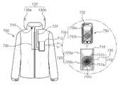
도 11은 본 발명의 제6실시예에 따른 의복형 컴퓨팅 시스템을 설명하기 위한 예시도이다. 도 12는 도 11의 의복형 컴퓨팅 시스템에서의 직물기반 자기장 인터페이스 의복 및 휴대 단말의 구성을 상세하게 설명하기 위한 블록도이다.11 is an exemplary diagram for describing a garment computing system according to a sixth embodiment of the present invention. FIG. 12 is a block diagram illustrating in detail a configuration of a fabric-based magnetic field interface garment and a portable terminal in the garment type computing system of FIG. 11.
본 발명의 제6실시예에 따른 의복형 컴퓨팅 시스템은 직물기반 자기장 인터페이스 의복(700, 이하 '의복') 및 휴대 단말(750)을 구비한다.The garment type computing system according to the sixth embodiment of the present invention includes a fabric-based magnetic field interface garment 700 (hereinafter, 'garment') and a
도 9 및 도 10을 참조하면, 의복(600)에는 수납부(710)가 형성되고, 그 수납부(710)에는 사용자의 휴대 단말(750)이 수납된다. 이때, 수납부(710)는 사이즈는 휴대 단말(750)의 사이즈와 동일하거나, 휴대 단말(750)이 수납되었을 때 약간의 유격만을 갖도록 형성되는 것이 바람직하다. 이는 의복(700)과 휴대 단말(750)이 비접촉식 자기장 통신을 수행함에 있어, 자속밀도를 높여 보다 안정적으로 자기장 통신을 수행할 수가 있도록 하기 위함이다.9 and 10, the
수납부(710)에는 휴대 단말(750)의 1차코일부(756)와 비접촉식 자기장 통신을 수행하는 2차코일부(714)와, 휴대 단말(750)의 자기장 센서부(752)에 자기 유도방식을 통해 마이크 신호를 전달하는 1차코일부(제3코일,712c)가 형성된다.In the
수납부(710)의 2차코일부(714)는 전도성사(직물형태의 도선)로 이루어진 제1 코일(712b) 및 제2코일(712a)로 구성된다.The
이때, 제1코일(712b)과 제2코일(712a)은 각각 서로 다른 축 배열을 갖도록 수납부(710)상에 형성된다. 예를 들어, 제1코일(712b)은 수납부(710)의 내부 혹은 외부면을 따라 X축 방향으로 권선되고, 제2코일(712a)은 수납부(710)의 내부 혹은 외부면을 따라 Y축 방향으로 권선된다(도 11 참조).In this case, the
2차코일부(714)의 제1코일(712b) 및 제2코일(712a)은 의복(700)에 형성된 전도성사(720)를 통해 외부의 오디오 출력장치(130, 예컨대 '이어폰')와 전기적으로 연결된다. 예를 들어, 2차코일부(714)의 제1코일(712b)은 제1전도성사(720b)를 통해 오디오 출력장치(130)의 R채널(130a)과 전기적으로 연결되고, 2차코일부(714)의 제2코일(712a)은 제2전도성사(712a)를 통해 오디오 출력장치(130)의 L채널(130b)과 전기적으로 연결될 수 있다.The
여기서, 제1코일(712b)과 제2코일(712a)은 특허청구범위에 기재된 제1오디오신호 수신코일과 제2오디오신호 수신코일에 각각 대응된다. 그리고, 아래의 제3코일(712c)은 특허청구범위에 기재된 마이크신호 전송코일에 대응된다.Here, the
또한, 수납부(710)에는 전도성사로 이루어진 1차코일부(제3코일,712c)가 형성되며, 제3코일(712c)은 2차코일부(714)의 제1코일(712b) 및 제2코일(712a)과 서로 다른 축 배열을 갖도록 수납부(710)에 형성된다. 예컨대, 제3코일(712c)은 수납부(710)의 내부 혹은 외부면에 Z 축 배열을 갖도록 회오리 형상으로 형성된다(도 11 참조).In addition, a primary coil part (third coil, 712c) formed of a conductive yarn is formed in the
그리고, 의복(700)은 신호 증폭부(748), 신호 생성부(746), 및 전원부(744) 를 구비한다.The
신호 생성부(746)는 전도성사(730)를 통해 음성입력장치(740, 예컨대 '마이크')와 전기적으로 연결되고, 음성입력장치(740)를 통해 사용자 음성을 입력받아 마이크 신호를 생성한다. 전원부(744)는 신호 생성부(746)에서 마이크 신호를 생성하기 위해 필요한 전력을 공급하고, 신호 증폭부(748)는 신호 생성부(746)에서 생성된 마이크 신호를 증폭하여 제3코일(712c)에 전달한다. 이에, 제3코일(712c)은 신호 증폭부(748)로부터 증폭된 마이크 신호를 전달받아 자기 유도방식을 통해 자기장 센서부(752)에 전달한다.The
한편, 휴대 단말(750)은 신호 변환부(762), 저주파신호 증폭부(764), 1차코일부(756), 자기장 센서부(752), 전원부(672), 및 신호 복원부(778)를 구비한다.Meanwhile, the
신호 변환부(762)는 오디오 신호를 입력받아 1차코일부(756)에서 자기 유도방식을 통해 오디오 신호를 전송할 수 있는 형태로 변환한다.The
신호 변환부(762)에서 변환된 신호는 저주파신호 증폭부(764)에 전달되고, 저주파신호 증폭부(764)는 이를 입력받아 저주파 대역의 신호를 증폭하여 1차코일부(756)의 제1코일(756a) 및 제2코일(756b)에 전달한다.The signal converted by the
1차코일부(756)에 전달된 오디오 신호는 자기 유도방식을 통해 의복(700)의 2차코일부(714)에 전달되고, 이렇게 전달된 신호는 의복(700)쪽에서의 별다른 회로 구성없이 오디오 출력장치(130)를 통해 출력된다. 즉, 1차코일부(756)의 제1코일(756a)에 전달된 오디오 신호는 자기 유도방식을 통해 2차코일부(714)의 제1코 일(712b)에 전달되고, 1차코일부(756)의 제2코일(756b)에 전달된 오디오 신호는 자기 유도방식을 통해 2차코일부(714)의 제2코일(712a)에 전달된다.The audio signal transmitted to the
여기서, 제1코일(756a)과 제2코일(756b)은 특허청구범위에 기재된 제1오디오신호 전송코일과 제2오디오신호 전송코일에 각각 대응된다.Here, the
자기장 센서부(752)는 자기 유도방식을 통해 의복(700)의 제3코일(712c)로부터 전달되는 마이크 신호를 감지하고, 감지한 마이크 신호를 신호 복원부(778)에 전달한다. 자기장 센서부(752)로는 제3코일(712c)로부터 전달되는 제어신호를 감지하기 위한 1축 자기장 센서 또는 자기유도를 할 수 있는 코일을 사용할 수 있다.The magnetic
신호 복원부(778)는 자기장 센서부(752)에서 감지한 마이크 신호를 밴드패스 필터 등을 이용하여 검출하고 복원한다.The
도 14는 본 발명의 의복형 컴퓨팅 시스템에 적용 가능한 자기장 인터페이스 장치의 일예를 나타낸 도면이다.14 is a diagram illustrating an example of a magnetic field interface device applicable to the garment computing system of the present invention.
한편, 앞서 언급한 설명 및 도면들에서는 도 14의 왼쪽 그림과 같이, 휴대 단말에 형성된 1차코일부 및 2차코일부가, 휴대 단말에 내장되어 구현되는 것으로 설명하였다. 하지만, 본 발명의 직물기반 자기장 인터페이스 의복와 자기장 통신을 수행할 수 있도록, 도 14의 오른쪽 그림과 같이 휴대 단말의 커넥터(예컨대, USB 커넥터, TTA 24핀 커넥터 등)에 접속되는 동글(dongle) 타입의 자기장 인터페이스 장치로 구현할 수 있다. 이때 자기장 인터페이스 상에 구현되는 코일의 형태 및 기능은 전술한 설명 및 도면들을 통해 당업자라면 용이하게 유추할 수 사항이다. 따 라서 더 이상의 상세한 설명은 생략하기로 한다.Meanwhile, in the above description and the drawings, as illustrated in the left figure of FIG. 14, the primary coil part and the secondary coil part formed in the portable terminal are described as being implemented in the portable terminal. However, in order to perform the magnetic field communication with the fabric-based magnetic field interface garment of the present invention, as shown in the right figure of Figure 14 of the dongle (dongle type) connected to the connector of the mobile terminal (eg, USB connector, TTA 24-pin connector, etc.) It can be implemented as a magnetic field interface device. In this case, the shape and function of the coil implemented on the magnetic field interface may be easily inferred by those skilled in the art through the foregoing description and drawings. Therefore, further detailed description will be omitted.
본 발명에 따른 의복형 컴퓨팅 시스템에서의 자기장 인터페이스 의복은 자기장을 이용하여 휴대 단말과 통신을 수행하기 때문에, 직접적인 커넥터 연결이나 RF를 이용한 무선 통신모듈(양 단에 전원구비)의 사용없이도 구현이 가능하다. 또한, 본 발명의 의복형 컴퓨팅 시스템은 의복 내의 어떤 부위에도 적용될 수 있으며, 의복과 휴대 단말이 근접 자기장 통신을 수행하기 때문에 통신의 보안성이 뛰어나다.The magnetic field interface garment in the garment computing system according to the present invention communicates with a mobile terminal using a magnetic field, so that it can be implemented without using a direct connector connection or a wireless communication module (power supply at both ends) using RF. Do. In addition, the garment-type computing system of the present invention can be applied to any part of the garment, and excellent security of communication because the garment and the mobile terminal performs the near-field communication.
본 발명의 일부 단계들은 컴퓨터가 읽을 수 있는 기록매체에 컴퓨터가 읽을 수 있는 코드로서 구현하는 것이 가능하다. 컴퓨터가 읽을 수 있는 기록매체는 컴퓨터 시스템에 의하여 읽혀질 수 있는 데이터가 저장되는 모든 종류의 기록 장치를 포함한다. 컴퓨터가 읽을 수 있는 기록 매체의 예로는 ROM, RAM, CD-ROM, CD-RW, 자기 테이프, 플로피디스크, HDD, 광 디스크, 광자기 저장장치 등이 있을 수 있으며, 또한 캐리어 웨이브(예를 들어, 인터넷을 통한 전송)의 형태로 구현되는 것도 포함한다. 또한 컴퓨터가 읽을 수 있는 기록 매체는 네트워크로 연결된 컴퓨터 시스템에 분산되어, 분산방식으로 컴퓨터가 읽을 수 있는 코드로 저장되고 실행될 수 있다.Some steps of the invention may be embodied as computer readable code on a computer readable recording medium. A computer-readable recording medium includes all kinds of recording apparatuses in which data that can be read by a computer system is stored. Examples of the computer-readable recording medium include ROM, RAM, CD-ROM, CD-RW, magnetic tape, floppy disk, HDD, optical disk, magneto optical storage, , Transmission over the Internet). The computer readable recording medium can also be distributed over network coupled computer systems so that the computer readable code is stored and executed in a distributed fashion.
이상에서와 같이 도면과 명세서에서 최적의 실시예가 개시되었다. 여기서 특정한 용어들이 사용되었으나, 이는 단지 본 발명을 설명하기 위한 목적에서 사용된 것이지 의미 한정이나 특허청구범위에 기재된 본 발명의 범위를 제한하기 위하여 사용된 것은 아니다. 그러므로, 본 기술 분야의 통상의 지식을 가진자라면 이로부터 다양한 변형 및 균등한 타 실시예가 가능하다는 점을 이해할 것이다. 따라서, 본 발명의 진정한 기술적 보호범위는 첨부된 특허청구범위의 기술적 사상에 의해 정해져야 할 것이다.As described above, an optimal embodiment has been disclosed in the drawings and specification. Although specific terms have been used herein, they are used only for the purpose of describing the present invention and are not used to limit the scope of the present invention as defined in the meaning or claims. Therefore, those skilled in the art will appreciate that various modifications and equivalent embodiments are possible without departing from the scope of the present invention. Accordingly, the true scope of the present invention should be determined by the technical idea of the appended claims.
도 1은 본 발명의 제1실시예에 따른 의복형 컴퓨팅 시스템을 설명하기 위한 예시도이다.1 is an exemplary diagram for describing a garment computing system according to a first embodiment of the present invention.
도 2는 도 1의 의복형 컴퓨팅 시스템에서의 직물기반 자기장 인터페이스 의복 및 휴대 단말의 구성을 상세하기 설명하기 위한 블록도이다.FIG. 2 is a block diagram illustrating in detail a configuration of a fabric-based magnetic field interface garment and a portable terminal in the garment type computing system of FIG. 1.
도 3은 본 발명의 제2실시예에 따른 의복형 컴퓨팅 시스템을 설명하기 위한 예시도이다.3 is an exemplary diagram for describing a garment computing system according to a second embodiment of the present invention.
도 4는 도 3의 의복형 컴퓨팅 시스템에서의 직물기반 자기장 인터페이스 의복 및 휴대 단말의 구성을 상세하게 설명하기 위한 블록도이다.FIG. 4 is a block diagram for describing in detail the fabric-based magnetic field interface garment and the portable terminal of the garment type computing system of FIG. 3.
도 5는 본 발명의 제3실시예에 따른 의복형 컴퓨팅 시스템을 설명하기 위한 예시도이다.5 is an exemplary diagram for describing a garment computing system according to a third embodiment of the present invention.
도 6은 도 5의 의복형 컴퓨팅 시스템에서의 직물기반 자기장 인터페이스 의복 및 휴대 단말의 구성을 상세하게 설명하기 위한 블록도이다.FIG. 6 is a block diagram illustrating in detail a fabric-based magnetic field interface garment and a portable terminal in the garment type computing system of FIG. 5.
도 7은 본 발명의 제4실시예에 따른 의복형 컴퓨팅 시스템을 설명하기 위한 예시도이다.7 is an exemplary diagram for describing a garment computing system according to a fourth embodiment of the present invention.
도 8은 도 7의 의복형 컴퓨팅 시스템에서의 직물기반 자기장 인터페이스 의복 및 휴대 단말의 구성을 상세하게 설명하기 위한 블록도이다.FIG. 8 is a block diagram illustrating in detail a fabric-based magnetic field interface garment and a portable terminal of the garment type computing system of FIG. 7.
도 9은 본 발명의 제5실시예에 따른 의복형 컴퓨팅 시스템을 설명하기 위한 예시도이다.9 is an exemplary view for explaining a garment-type computing system according to a fifth embodiment of the present invention.
도 10은 도 9의 의복형 컴퓨팅 시스템에서의 직물기반 자기장 인터페이스 의 복 및 휴대 단말의 구성을 상세하게 설명하기 위한 블록도이다.FIG. 10 is a block diagram illustrating in detail a configuration of a cloth-based magnetic field interface garment and a portable terminal in the garment computing system of FIG. 9.
도 11은 본 발명의 제6실시예에 따른 의복형 컴퓨팅 시스템을 설명하기 위한 예시도이다.11 is an exemplary diagram for describing a garment computing system according to a sixth embodiment of the present invention.
도 12는 도 11의 의복형 컴퓨팅 시스템에서의 직물기반 자기장 인터페이스 의복 및 휴대 단말의 구성을 상세하게 설명하기 위한 블록도이다.FIG. 12 is a block diagram illustrating in detail a configuration of a fabric-based magnetic field interface garment and a portable terminal in the garment type computing system of FIG. 11.
도 13은 비접촉식 자기장 통신을 통해 전송된 오디오 신호의 주파수 특성을 설명하기 위한 도면이다.FIG. 13 is a diagram for describing frequency characteristics of an audio signal transmitted through contactless magnetic field communication.
도 14는 본 발명의 의복형 컴퓨팅 시스템에 적용 가능한 자기장 인터페이스 장치의 일예를 나타낸 도면이다.14 is a diagram illustrating an example of a magnetic field interface device applicable to the garment computing system of the present invention.
Claims (19)
Translated fromKoreanPriority Applications (2)
| Application Number | Priority Date | Filing Date | Title |
|---|---|---|---|
| KR1020090084115AKR101249736B1 (en) | 2009-09-07 | 2009-09-07 | Textile-based magnetic field interface clothes and mobile terminal in wearable computing system |
| US12/875,418US8509470B2 (en) | 2009-09-07 | 2010-09-03 | Textile-based magnetic field interface clothes and mobile terminal in wearable computing system |
Applications Claiming Priority (1)
| Application Number | Priority Date | Filing Date | Title |
|---|---|---|---|
| KR1020090084115AKR101249736B1 (en) | 2009-09-07 | 2009-09-07 | Textile-based magnetic field interface clothes and mobile terminal in wearable computing system |
Publications (2)
| Publication Number | Publication Date |
|---|---|
| KR20110026284A KR20110026284A (en) | 2011-03-15 |
| KR101249736B1true KR101249736B1 (en) | 2013-04-03 |
Family
ID=43647796
Family Applications (1)
| Application Number | Title | Priority Date | Filing Date |
|---|---|---|---|
| KR1020090084115AExpired - Fee RelatedKR101249736B1 (en) | 2009-09-07 | 2009-09-07 | Textile-based magnetic field interface clothes and mobile terminal in wearable computing system |
Country Status (2)
| Country | Link |
|---|---|
| US (1) | US8509470B2 (en) |
| KR (1) | KR101249736B1 (en) |
Families Citing this family (15)
| Publication number | Priority date | Publication date | Assignee | Title |
|---|---|---|---|---|
| KR101269211B1 (en)* | 2009-09-24 | 2013-05-30 | 한국전자통신연구원 | Textile-type interface devices for optical communication in wearable computing system |
| US8898816B2 (en)* | 2011-06-03 | 2014-12-02 | Kimberly K. Highfield | Women's sports top with integrated pocket assembly |
| KR20130126760A (en)* | 2012-03-05 | 2013-11-21 | 한국전자통신연구원 | Apparatus and method for textile-type interface in human wearing band |
| US20150061914A1 (en)* | 2012-11-09 | 2015-03-05 | Robert Falken | Radiation attenuating clothing |
| US9467207B2 (en)* | 2013-09-12 | 2016-10-11 | The United States Of America As Represented By The Secretary Of The Army | System for transferring electrical energy |
| KR20160100091A (en) | 2015-02-13 | 2016-08-23 | 조철호 | Clothes of having storage space for portable terminal and clothes manufacturing method thereof, and service providing method for portable terminal inserted in clothes |
| US9537321B2 (en) | 2015-02-25 | 2017-01-03 | Motorola Solutions, Inc. | Method and apparatus for power transfer for a portable electronic device |
| US10141092B2 (en)* | 2015-02-27 | 2018-11-27 | Charles Stuart Bennett | Pocket holster |
| KR101788805B1 (en)* | 2015-12-29 | 2017-10-23 | 상명대학교산학협력단 | Garment that generates energy by reciprocal movement |
| US11291257B2 (en)* | 2016-12-13 | 2022-04-05 | Kim Epp Frenette | Apparel with integrated storage |
| CN109803188B (en)* | 2018-12-27 | 2020-09-22 | 维沃移动通信有限公司 | Electronic device and earphone |
| DE102019200745A1 (en) | 2019-01-22 | 2020-07-23 | UVEX SAFETY GROUP GmbH & Co. KG | Protective equipment for body protection of a person and detection device for determining usage data on the protective equipment |
| CN110547531A (en)* | 2019-09-19 | 2019-12-10 | 张明华 | Anti-theft pocket and garment |
| USD945124S1 (en)* | 2020-07-30 | 2022-03-08 | Kirk Yancey | Shirt with a centered pocket |
| USD1060937S1 (en)* | 2021-01-20 | 2025-02-11 | Maurice Atkins | Combined t-shirt with recording module |
Citations (3)
| Publication number | Priority date | Publication date | Assignee | Title |
|---|---|---|---|---|
| KR20060090112A (en)* | 2005-02-07 | 2006-08-10 | 박관식 | Wireless Transceiver System Using Electromagnetic Induction |
| KR20080088795A (en)* | 2007-03-30 | 2008-10-06 | 한국과학기술원 | Power transmission device using mutual inductance |
| KR20090066513A (en)* | 2007-12-20 | 2009-06-24 | 연세대학교 산학협력단 | Smart bag and wireless connection system in clothing |
Family Cites Families (9)
| Publication number | Priority date | Publication date | Assignee | Title |
|---|---|---|---|---|
| US5568516A (en)* | 1993-07-02 | 1996-10-22 | Phonic Ear Incorporated | Very low power cordless headset system |
| FR2756953B1 (en) | 1996-12-10 | 1999-12-24 | Innovatron Ind Sa | PORTABLE TELEALIMENTAL OBJECT FOR CONTACTLESS COMMUNICATION WITH A TERMINAL |
| KR20040006387A (en) | 2002-07-12 | 2004-01-24 | 신인섭 | Radio ear-phone for use in ear |
| JP2007506334A (en)* | 2003-09-22 | 2007-03-15 | コニンクリユケ フィリップス エレクトロニクス エヌ.ブイ. | Electrical device, system, and method |
| CN1890855A (en) | 2003-12-03 | 2007-01-03 | 皇家飞利浦电子股份有限公司 | A garment including an inductive button and buttonhole |
| DE102004047650B3 (en) | 2004-09-30 | 2006-04-13 | W.L. Gore & Associates Gmbh | Garment with inductive coupler and inductive garment interface |
| US7627289B2 (en)* | 2005-12-23 | 2009-12-01 | Plantronics, Inc. | Wireless stereo headset |
| KR100859320B1 (en) | 2007-02-06 | 2008-09-19 | 한국과학기술원 | Non-contact communication device |
| US20100081379A1 (en)* | 2008-08-20 | 2010-04-01 | Intel Corporation | Wirelessly powered speaker |
- 2009
- 2009-09-07KRKR1020090084115Apatent/KR101249736B1/ennot_activeExpired - Fee Related
- 2010
- 2010-09-03USUS12/875,418patent/US8509470B2/ennot_activeExpired - Fee Related
Patent Citations (3)
| Publication number | Priority date | Publication date | Assignee | Title |
|---|---|---|---|---|
| KR20060090112A (en)* | 2005-02-07 | 2006-08-10 | 박관식 | Wireless Transceiver System Using Electromagnetic Induction |
| KR20080088795A (en)* | 2007-03-30 | 2008-10-06 | 한국과학기술원 | Power transmission device using mutual inductance |
| KR20090066513A (en)* | 2007-12-20 | 2009-06-24 | 연세대학교 산학협력단 | Smart bag and wireless connection system in clothing |
Also Published As
| Publication number | Publication date |
|---|---|
| US8509470B2 (en) | 2013-08-13 |
| KR20110026284A (en) | 2011-03-15 |
| US20110058705A1 (en) | 2011-03-10 |
Similar Documents
| Publication | Publication Date | Title |
|---|---|---|
| KR101249736B1 (en) | Textile-based magnetic field interface clothes and mobile terminal in wearable computing system | |
| JP5921689B2 (en) | Apparatus, method, and computer readable medium for receiving wireless power using a plurality of power receiving coils | |
| CN105844189B (en) | The optimization of wireless power device for charging the battery | |
| CN102318216B (en) | Electronic device and method for providing wireless charging power | |
| US9130394B2 (en) | Wireless power for charging devices | |
| KR101574322B1 (en) | Wireless communication multiplex antenna for portable electronic appliance | |
| EP2984735B1 (en) | Wireless device charging system having a shared antenna | |
| CN104981957A (en) | Active and adaptive field cancellation for wireless power systems | |
| US12224108B2 (en) | Coil module | |
| CN113765231B (en) | Wireless charging coils in wearable devices | |
| US20250158432A1 (en) | Wireless Power Transfer System For Listening Devices With Expandable Case | |
| CN217183038U (en) | Wireless earplug and wireless power system | |
| US12212156B2 (en) | Reconfigurable wireless power transmitter for computer peripherals | |
| JP7654823B2 (en) | Magnetic configurations for wireless power transfer and communication in electronic devices | |
| US20250158431A1 (en) | Wireless Power Transfer System For Listening Devices | |
| WO2016076498A1 (en) | Coil-type loop antenna for mobile device | |
| US20230275458A1 (en) | On-Ear Charging For Wireless Hearables | |
| JP4333301B2 (en) | Communication device | |
| JP2016142554A (en) | Vibration measurement device and vibration measurement system | |
| US20240147122A1 (en) | Wireless power transfer system for wearable communication devices | |
| US20240146106A1 (en) | Wireless power transfer system for wearable communication devices with attachable power source | |
| US20240146107A1 (en) | Computing device based wireless power transmitters for wearable communication devices | |
| US20240147123A1 (en) | Through headband wireless power transfer system for wearable communication devices | |
| KR20150129598A (en) | Dual type charging apparatus for portable terminal | |
| WO2024092231A1 (en) | Wireless power transfer system for wearable communication devices |
Legal Events
| Date | Code | Title | Description |
|---|---|---|---|
| A201 | Request for examination | ||
| PA0109 | Patent application | St.27 status event code:A-0-1-A10-A12-nap-PA0109 | |
| PA0201 | Request for examination | St.27 status event code:A-1-2-D10-D11-exm-PA0201 | |
| PG1501 | Laying open of application | St.27 status event code:A-1-1-Q10-Q12-nap-PG1501 | |
| E902 | Notification of reason for refusal | ||
| PE0902 | Notice of grounds for rejection | St.27 status event code:A-1-2-D10-D21-exm-PE0902 | |
| E13-X000 | Pre-grant limitation requested | St.27 status event code:A-2-3-E10-E13-lim-X000 | |
| P11-X000 | Amendment of application requested | St.27 status event code:A-2-2-P10-P11-nap-X000 | |
| P13-X000 | Application amended | St.27 status event code:A-2-2-P10-P13-nap-X000 | |
| E90F | Notification of reason for final refusal | ||
| PE0902 | Notice of grounds for rejection | St.27 status event code:A-1-2-D10-D21-exm-PE0902 | |
| P11-X000 | Amendment of application requested | St.27 status event code:A-2-2-P10-P11-nap-X000 | |
| P13-X000 | Application amended | St.27 status event code:A-2-2-P10-P13-nap-X000 | |
| E701 | Decision to grant or registration of patent right | ||
| PE0701 | Decision of registration | St.27 status event code:A-1-2-D10-D22-exm-PE0701 | |
| GRNT | Written decision to grant | ||
| PR0701 | Registration of establishment | St.27 status event code:A-2-4-F10-F11-exm-PR0701 | |
| PR1002 | Payment of registration fee | St.27 status event code:A-2-2-U10-U11-oth-PR1002 Fee payment year number:1 | |
| PG1601 | Publication of registration | St.27 status event code:A-4-4-Q10-Q13-nap-PG1601 | |
| PN2301 | Change of applicant | St.27 status event code:A-5-5-R10-R13-asn-PN2301 St.27 status event code:A-5-5-R10-R11-asn-PN2301 | |
| FPAY | Annual fee payment | Payment date:20160226 Year of fee payment:4 | |
| PR1001 | Payment of annual fee | St.27 status event code:A-4-4-U10-U11-oth-PR1001 Fee payment year number:4 | |
| PN2301 | Change of applicant | St.27 status event code:A-5-5-R10-R11-asn-PN2301 | |
| PN2301 | Change of applicant | St.27 status event code:A-5-5-R10-R14-asn-PN2301 | |
| P14-X000 | Amendment of ip right document requested | St.27 status event code:A-5-5-P10-P14-nap-X000 | |
| P16-X000 | Ip right document amended | St.27 status event code:A-5-5-P10-P16-nap-X000 | |
| Q16-X000 | A copy of ip right certificate issued | St.27 status event code:A-4-4-Q10-Q16-nap-X000 | |
| PR1001 | Payment of annual fee | St.27 status event code:A-4-4-U10-U11-oth-PR1001 Fee payment year number:5 | |
| LAPS | Lapse due to unpaid annual fee | ||
| PC1903 | Unpaid annual fee | St.27 status event code:A-4-4-U10-U13-oth-PC1903 Not in force date:20180328 Payment event data comment text:Termination Category : DEFAULT_OF_REGISTRATION_FEE | |
| PC1903 | Unpaid annual fee | St.27 status event code:N-4-6-H10-H13-oth-PC1903 Ip right cessation event data comment text:Termination Category : DEFAULT_OF_REGISTRATION_FEE Not in force date:20180328 | |
| P22-X000 | Classification modified | St.27 status event code:A-4-4-P10-P22-nap-X000 |