KR101248870B1 - Toner supply apparatus, developing apparatus and image forming apparatus having the toner supply apparatus - Google Patents
Toner supply apparatus, developing apparatus and image forming apparatus having the toner supply apparatusDownload PDFInfo
- Publication number
- KR101248870B1 KR101248870B1KR1020060081154AKR20060081154AKR101248870B1KR 101248870 B1KR101248870 B1KR 101248870B1KR 1020060081154 AKR1020060081154 AKR 1020060081154AKR 20060081154 AKR20060081154 AKR 20060081154AKR 101248870 B1KR101248870 B1KR 101248870B1
- Authority
- KR
- South Korea
- Prior art keywords
- toner
- developing
- clutch
- color
- spring
- Prior art date
- Legal status (The legal status is an assumption and is not a legal conclusion. Google has not performed a legal analysis and makes no representation as to the accuracy of the status listed.)
- Expired - Fee Related
Links
Images


Classifications
- G—PHYSICS
- G03—PHOTOGRAPHY; CINEMATOGRAPHY; ANALOGOUS TECHNIQUES USING WAVES OTHER THAN OPTICAL WAVES; ELECTROGRAPHY; HOLOGRAPHY
- G03G—ELECTROGRAPHY; ELECTROPHOTOGRAPHY; MAGNETOGRAPHY
- G03G15/00—Apparatus for electrographic processes using a charge pattern
- G03G15/06—Apparatus for electrographic processes using a charge pattern for developing
- G03G15/08—Apparatus for electrographic processes using a charge pattern for developing using a solid developer, e.g. powder developer
- G03G15/0822—Arrangements for preparing, mixing, supplying or dispensing developer
- G03G15/0877—Arrangements for metering and dispensing developer from a developer cartridge into the development unit
- G—PHYSICS
- G03—PHOTOGRAPHY; CINEMATOGRAPHY; ANALOGOUS TECHNIQUES USING WAVES OTHER THAN OPTICAL WAVES; ELECTROGRAPHY; HOLOGRAPHY
- G03G—ELECTROGRAPHY; ELECTROPHOTOGRAPHY; MAGNETOGRAPHY
- G03G15/00—Apparatus for electrographic processes using a charge pattern
- G03G15/06—Apparatus for electrographic processes using a charge pattern for developing
- G03G15/08—Apparatus for electrographic processes using a charge pattern for developing using a solid developer, e.g. powder developer
- G03G15/0822—Arrangements for preparing, mixing, supplying or dispensing developer
- G03G15/0865—Arrangements for supplying new developer
- G03G15/0867—Arrangements for supplying new developer cylindrical developer cartridges, e.g. toner bottles for the developer replenishing opening
- G03G15/0868—Toner cartridges fulfilling a continuous function within the electrographic apparatus during the use of the supplied developer material, e.g. toner discharge on demand, storing residual toner, acting as an active closure for the developer replenishing opening
- G—PHYSICS
- G03—PHOTOGRAPHY; CINEMATOGRAPHY; ANALOGOUS TECHNIQUES USING WAVES OTHER THAN OPTICAL WAVES; ELECTROGRAPHY; HOLOGRAPHY
- G03G—ELECTROGRAPHY; ELECTROPHOTOGRAPHY; MAGNETOGRAPHY
- G03G2215/00—Apparatus for electrophotographic processes
- G03G2215/06—Developing structures, details
- G03G2215/066—Toner cartridge or other attachable and detachable container for supplying developer material to replace the used material
- G03G2215/0685—Toner cartridge or other attachable and detachable container for supplying developer material to replace the used material fulfilling a continuous function within the electrographic apparatus during the use of the supplied developer material, e.g. toner discharge on demand, storing residual toner, not acting as a passive closure for the developer replenishing opening
- G—PHYSICS
- G03—PHOTOGRAPHY; CINEMATOGRAPHY; ANALOGOUS TECHNIQUES USING WAVES OTHER THAN OPTICAL WAVES; ELECTROGRAPHY; HOLOGRAPHY
- G03G—ELECTROGRAPHY; ELECTROPHOTOGRAPHY; MAGNETOGRAPHY
- G03G2221/00—Processes not provided for by group G03G2215/00, e.g. cleaning or residual charge elimination
- G03G2221/16—Mechanical means for facilitating the maintenance of the apparatus, e.g. modular arrangements and complete machine concepts
- G03G2221/1651—Mechanical means for facilitating the maintenance of the apparatus, e.g. modular arrangements and complete machine concepts for connecting the different parts
- G03G2221/1657—Mechanical means for facilitating the maintenance of the apparatus, e.g. modular arrangements and complete machine concepts for connecting the different parts transmitting mechanical drive power
Landscapes
- Physics & Mathematics (AREA)
- General Physics & Mathematics (AREA)
- Dry Development In Electrophotography (AREA)
- Electrophotography Configuration And Component (AREA)
- Color Electrophotography (AREA)
Abstract
Translated fromKoreanDescription
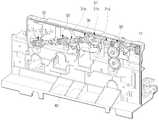
Translated fromKorean도 1은 본 발명의 일 실시예에 의한 토너 공급장치를 개략적으로 나타낸 사사시도,1 is a perspective view schematically showing a toner supply apparatus according to an embodiment of the present invention;
도 2는 도 1에서 토너용기를 제거한 상태의 사시도,Figure 2 is a perspective view of the toner container removed from Figure 1,
도 3은 본 발명의 요부 상세도,3 is a detailed view of the main part of the present invention;
도 4a 및 4b는 본 발명의 요부인 스프링 클러치의 조립 사시도 및 분해 사시도,4a and 4b is an assembled perspective view and an exploded perspective view of the spring clutch, which is the main part of the present invention;
도 5는 본 발명의 요부인 스프링 클러치의 작용을 설명하기 위한 도면, 그리고,5 is a view for explaining the operation of the spring clutch which is the main part of the present invention, and
도 6은 본 발명의 일 실시예에 의한 토너 공급장치가 채용된 현상장치를 구비하는 화상형성장치를 개략적으로 나타낸 도면이다.6 is a schematic view of an image forming apparatus including a developing apparatus employing a toner supplying apparatus according to an embodiment of the present invention.
< 도면의 주요 부분에 대한 부호의 설명 >Description of the Related Art
10;구동원20;토너용기10;
30;스프링 클러치31;구동축30;
32;클러치 허브33;클러치 칼라32;
34;제 1 기어부재(웜)35;스프링34; first gear member (worm) 35; spring
36;솔레노이드37;제 2 기어부재(웜기어)36;
38;아이들기어39;제 3 기어부재38; idler
40;현상케이스50;토너량 감지센서유닛40; developing
60;제어부100;현상장치60;
110;토너수용부120;현상롤러110;
200;감광매체300;T1 전사롤러200;
400;중간전사벨트500;T2 전사롤러400;
본 발명은 토너 리필형 컬러 화상형성장치의 색상별 토너 공급장치 및 이를 구비하는 현상장치, 그리고, 상기 현상장치를 채용한 화상형성장치에 관한 것이다.The present invention relates to a toner supply apparatus for each color of a toner refill type color image forming apparatus, a developing apparatus having the same, and an image forming apparatus employing the developing apparatus.
토너 리필형 컬러 화상형성장치는 색상별 토너, 예컨대 옐로우(Yellow), 마젠타(Magenta), 시안(Cyan), 블랙(blacK) 색상의 토너를 각각 저장하는 4개의 토너용기를 구비한다. 상기 4개의 토너용기는 토너용기 내부의 토너를 외부로 배출시키기 위한 토너배출부재, 즉 오거(Auger)를 구비한다.The toner refill type color image forming apparatus includes four toner containers for storing color toners, for example, toners of yellow, magenta, cyan, and blacK colors. The four toner containers include a toner discharge member, that is, an auger, for discharging the toner inside the toner container to the outside.
상기 오거들은 하나의 동력원으로부터 전달되는 동력에 의해 회전하는데, 각각 전자클러치의 개재하에 상기 동력원과 연결되어 있으므로 부족한 색상의 토너가 들어있는 토너용기의 오거만을 회전 구동시켜서 해당 색상의 토너를 현상장치로 공 급할 수 있다. 이 때, 다른 색상의 토너가 들어있는 3개 토너용기의 오거는 전자클러치가 오프 상태이므로 회전하지 않는다.The augers are rotated by the power transmitted from one power source, and each of the augers is connected to the power source through an electronic clutch, so only the auger of the toner container containing insufficient toner is rotated to transfer the toner of the corresponding color to the developing apparatus. Can be supplied. At this time, the auger of the three toner containers containing toners of different colors does not rotate because the electronic clutch is in the off state.
그러나, 색상별 토너를 개별적으로 공급할 수 있는 토너 공급장치에서 동력단속유닛으로서 상기한 바와 같은 전자클러치를 이용하면, 전자클러치의 자체 크기 등으로 인해 현상장치의 크기가 커지며, 또한, 전자클러치의 비싼 가격으로 인해 현상장치 및/또는 화상형성장치의 제조 비용이 높아지는 문제가 있다.However, when the electronic clutch as described above is used as the power interruption unit in the toner supply apparatus capable of supplying the toner for each color individually, the size of the developing apparatus is increased due to the size of the electronic clutch, etc., and the electronic clutch is expensive. Due to the price, there is a problem that the manufacturing cost of the developing apparatus and / or the image forming apparatus becomes high.
본 발명은 상기와 같은 점을 감안하여 안출한 것으로, 저가이며 소형의 스프링 클러치를 동력단속유닛으로 채용함으로써 현상장치 및/또는 화상형성장치의 소형화를 도모함과 아울러 제조 비용을 절감시킬 수 있는 토너 공급장치를 제공하는데 그 목적이 있다.SUMMARY OF THE INVENTION The present invention has been made in view of the above, and a toner supply which can reduce the manufacturing cost and reduce the manufacturing cost by employing a low-cost, small-size spring clutch as a power control unit. The purpose is to provide a device.
본 발명의 다른 목적은 상기와 같은 특징을 가지는 토너 공급장치를 구비한 현상장치 및 화상형성장치를 제공하는데 있다.Another object of the present invention is to provide a developing apparatus and an image forming apparatus having a toner supply apparatus having the above characteristics.
상기 목적을 달성하기 위한 본 발명에 의한 토너 공급장치는, 구동원; 각기 다른 색상의 토너가 수용되어 있으며, 내부에는 상기 구동원으로부터 동력을 전달받아 구동하면서 토너를 배출시키는 토너배출부재가 각각 마련된 다수의 토너용기; 및 상기 구동원의 동력을 상기 토너배출부재로 선택적으로 전달시키기 위한 다수의 스프링 클러치;를 포함한다.Toner supply apparatus according to the present invention for achieving the above object, a drive source; A plurality of toner containers containing toners of different colors, each having a toner discharge member for discharging the toner while driving by receiving power from the driving source; And a plurality of spring clutches for selectively transmitting power of the drive source to the toner discharge member.
상기 스프링 클러치는, 상기 구동원에 결합된 구동축; 상기 구동축에 구동축 과 함께 항시 회전하도록 결합된 클러치 허브; 상기 구동축에 선택적으로 회전하도록 설치된 클러치 칼라; 상기 구동축에 선택적으로 회전하도록 설치된 제 1 기어부재; 일단은 상기 클러치 칼라에 고정되고, 타단은 상기 제 1 기어부재에 고정된 상태로 상기 클러치 허브와 상기 제 1 기어부재를 연결하는 스프링; 및 상기 클러치 칼라의 회전을 정지시켜 상기 스프링과 상기 클러치 허브의 연결을 해제하는 솔레노이드;를 포함하는 것이 바람직하다.The spring clutch, the drive shaft coupled to the drive source; A clutch hub coupled to the drive shaft at all times to rotate with the drive shaft; A clutch collar installed to selectively rotate on the drive shaft; A first gear member installed to selectively rotate on the drive shaft; A spring having one end fixed to the clutch collar and the other end connected to the clutch hub and the first gear member in a state of being fixed to the first gear member; And a solenoid for stopping the rotation of the clutch collar to release the connection between the spring and the clutch hub.
또한, 본 발명은 상기 제 1 기어부재와 치합하는 제 2 기어부재를 포함하며, 상기 제 1 및 제 2 기어부재는 웜 및 웜기어의 동력전달구조를 갖는 것이 바람직하다.In addition, the present invention includes a second gear member meshing with the first gear member, the first and second gear members preferably have a power transmission structure of the worm and worm gear.
또한, 상기 구동축과 상기 클러치 허브는 스플라인 축결합 또는 세레이션 축결합된 것이 바람직하다.In addition, the drive shaft and the clutch hub is preferably a spline shaft coupling or serration shaft coupling.
본 발명의 바람직한 실시예에 의하면, 토너 공급장치는 4개의 색상별 토너용기와 각 토너용기의 토너배출부재로의 동력 단속을 위한 4개의 스프링 클러치를 구비하는 것이 좋다.According to a preferred embodiment of the present invention, it is preferable that the toner supply apparatus includes four spring clutches for power interruption of the four color toner containers and the toner discharge member of each toner container.
본 발명의 다른 목적을 달성하기 위한 현상장치는, 색상별 토너가 수용되는 다수의 토너수용부를 구비한 현상케이스; 상기 현상케이스의 토너수용부 단부에 각각 설치된 현상롤러; 및 상기 각 토너수용부로 해당하는 토너의 개별 공급이 가능한 상술한 바와 같은 토너 공급장치;를 포함한다.A developing apparatus for achieving another object of the present invention, a developing case having a plurality of toner receiving portion for accommodating toner for each color; Developing rollers installed at each end of the toner accommodating part of the developing case; And a toner supply device as described above capable of individually supplying corresponding toner to each of the toner accommodating parts.
본 발명의 바람직한 실시예에 의하면 현상장치는 상기 각 토너수용부의 토너량을 감지하는 색상별 토너량 감지센서유닛; 및 상기 색상별 토너량 감지센서유닛 으로부터 정보를 입력받아 토너가 부족한 토너수용부를 인지하여 해당하는 솔레노이드를 구동시키는 제어부;를 포함하는 것이 좋다.According to a preferred embodiment of the present invention, the developing apparatus includes: a color toner amount sensor unit for detecting the toner amount of each toner accommodating part; And a controller for receiving information from the color toner amount sensor unit for each color and recognizing a toner-receiving unit lacking toner, thereby driving a corresponding solenoid.
한편, 본 발명의 다른 목적을 달성하기 위한 화상형성장치는 정전잠상이 형성되는 감광매체; 상기 감광매체에 색상별 토너를 이동 부착하여 상기 정전잠상을 현상하는 현상장치; 현상된 감광매체상의 토너 화상을 중첩 전사받는 중간전사벨트; 및 상기 중간전사벨트의 토너 화상을 인쇄매체로 전사하는 전사유닛;을 포함한다. 상기 현상장치는, 색상별 토너가 수용되는 다수의 토너수용부를 구비한 현상케이스; 상기 현상케이스의 토너수용부 단부에 각각 설치된 현상롤러; 및 상기 각 토너수용부로 해당하는 토너의 개별 공급이 가능한 상술한 바와 같은 토너 공급장치;를 포함한다.Meanwhile, an image forming apparatus for achieving another object of the present invention includes a photosensitive medium on which an electrostatic latent image is formed; A developing apparatus for developing the electrostatic latent image by moving and attaching the color toner to the photosensitive medium; An intermediate transfer belt for superimposing a toner image on the developed photosensitive medium; And a transfer unit for transferring the toner image of the intermediate transfer belt to a print medium. The developing apparatus includes a developing case having a plurality of toner accommodating parts for accommodating color toner; Developing rollers installed at each end of the toner accommodating part of the developing case; And a toner supply device as described above capable of individually supplying corresponding toner to each of the toner accommodating parts.
본 발명의 상기와 같은 목적 및 다른 특징들은 첨부도면을 참조하여 바람직한 실시예를 상세히 설명함으로써 더욱 명백해질 것이다. 참고로 본 발명을 설명함에 있어서 관련된 공지 기능 혹은 구성에 대한 구체적인 설명이 본 발명의 요지를 불필요하게 흐릴 수 있다고 판단되는 경우 그 상세한 설명을 생략한다.The above objects and other features of the present invention will become more apparent by describing the preferred embodiments in detail with reference to the accompanying drawings. In the following description, well-known functions or constructions are not described in detail to avoid unnecessarily obscuring the subject matter of the present invention.
도 1 내지 도 3은 본 발명의 일 실시예에 의한 화상형성장치의 토너 공급장치를 나타낸 도면들이다. 도면에서 부호 10은 구동원, 20은 토너용기, 30은 스프링 클러치, 40은 현상케이스이다.1 to 3 are views showing a toner supply apparatus of an image forming apparatus according to an embodiment of the present invention. In the drawings,
상기 구동원(10)은 상기 현상케이스(40)의 일측에 회전 가능하게 설치된 구동기어로 구성되며, 이 경우 도시되지 않은 기어 트레인 등을 통하여 다른 동력장치와 연결됨으로써 동력을 전달받을 수 있다. 대안적으로 상기 구동원(10)은 별도 의 모터 등으로 구성될 수도 있다.The
상기 토너용기(20)은 Y,M,C,K 토너를 각각 수용하는 4개로 구비되며, 상기 현상케이스(40)의 적소에 배치되고, 착탈 가능하다. 또한, 구체적으로 도시하지 않았으나, 각각의 토너용기(20)는 상기 구동원(10)으로부터 동력을 전달받아 구동하면서 토너용기 내부의 토너를 외부로 배출시키는 오거 등과 같은 토너배출부재를 구비한다. 상기 토너배출부재의 구동에 의해 토너용기에서 배출되는 토너는 현상케이스(40)에 색상별로 구비된 토너수용부(110);(도 6 참조)로 공급된다.The
상기 스프링 클러치(30)는 상기 구동원(10)의 동력을 상기 토너배출부재로 선택적으로 전달시키기 위한 것이다. 이러한 스프링 클러치(30)는 토너용기(20)의 수와 같은 4개로 마련되며, 이에 의해 해당하는 토너용기(20)의 토너배출부재를 구동시켜서 부족한 토너만을 현상장치(100:도 6 참조)의 토너수용부(110:도 6 참조)로 공급할 수 있다.The
상기와 같은 스프링 클러치(30)는 도 3, 도 4a 및 4b에 도시된 바와 같이, 상기 구동원(10)과 결합된 구동축(31), 상기 구동축(31)과 항시 함께 회전하도록 구동축(31)에 결합된 클러치 허브(32), 상기 구동축(31)에 선택적으로 회전하도록 설치된 클러치 칼라(33) 및 제 1 기어부재(34), 상기 클러치 허브(32)와 상기 제 1 기어부재(34)를 선택적으로 연결하여 동력이 전달되도록 하는 스프링(35) 및 상기 클러치 칼라(33)의 회전을 정지시켜 상기 스프링(35)과 상기 클러치 허브(32)의 연결을 해제하는 솔레노이드(36)를 구비한다.As shown in FIGS. 3, 4A, and 4B, the
상기 구동축(31)은 도시예에서는 제 1 축(31a) 및 제 2 축(31b)이 유니버셜 조인트(31c)에 의해 연결된 구조가 도시되어 있으나, 이는 4개 토너용기(20)의 배치가 도면에서와 같이 경사지게 배치됨으로써 구성한 것일 뿐 그러한 구조로 한정하는 것은 아니다. 예컨대, 도시예의 구조에서도 하나의 구동축(31)을 채용하고 이 구동축(31)과 토너용기(20) 사이에 아이들 기어(도시안됨)를 배치하여 동력전달이 이루어지도록 할 수 있을 것이다. 또한, 4개의 토너용기(20)를 도시예에서와 같이 경사지게 배치하지 않고 일직선으로 배치하는 경우에는 하나의 구동축을 채용하여도 별도의 아이들 기어 없이 동력 전달이 가능할 것이다.The
상기 클러치 허브(32)는 상기 구동축(31)에 스플라인 또는 세레이션 축결합되며, 이에 의해 상기 클러치 허브(32)는 상기 구동축(31)이 회전하면 항시 함께 회전하도록 되어 있다. 상기 클러치 허브(32)는 드럼부(32a)를 구비한다. 도면에서 부호 32d는 클러치 허브(32)의 스플라인 또는 세레이션 축결합을 위한 키홈이다. 구동축(31)에는 상기 키홈(32d)과 대응하는 돌기(31d)가 마련된다.The
상기 클러치 칼라(33)는 드럼부(33a)와 래치부(33b)를 구비하며, 구동축(31)에 선택적으로 회전하도록 설치된다. 이 클러치 칼라(33)의 안쪽으로 상기한 클러치 허브(32)가 배치되며, 클러치 칼라(33)의 내주면과 클러치 허브(32)의 외주면 사이에는 소정 간격이 존재한다.The
상기 제 1 기어부재(34)는, 예컨대 웜으로 구성되며, 드럼부(34a)을 구비한다. 이 제 1 기어부재(34)는 상기 클러치 칼라(33)와 마찬가지로 구동축(31)에 선택적으로 회전하도록 설치된다. 또한, 상기 제 1 기어부재(34)와 치합되는 제 2 기어부재(37)가 구비되는데, 이 기어부재(37)는 웜기어로 구성된다. 또 도 3에 도시 된 바와 같이, 상기 제 2 기어부재(37)에는 아이들기어(38)가 치합될 수 있으며, 이 아이들기어(38)에 토너용기(20) 내의 토너배출부재와 연결되는 연결부(39a)를 갖춘 제 3 기어부재(39)가 치합될 수 있다.The
도면에서는 블랙 토너용기(20)와 구동축(31) 사이가 멀어 아이들기어(38)와 제 3 기어부재(39)를 이용하여 토너배출부재로의 동력전달경로를 이루었으나, 토너용기(20)와 구동축(31)이 가까운 위치에서는, 상기 제 3 기어부재를 사용하지 않고 예컨대, 상기한 제 2 기어부재(37)나 아이들기어(38)에 토너배출부재 연결부를 형성하여 구성하는 것도 가능하다.Although the
상기 스프링(35)은 상기 클러치 허브(32)의 드럼부(32a)와 상기 제 1 기어부재(34)의 드럼부(34a)를 감싸도록 설치된다. 그 일단(35a)은 상기 클러치 칼라(33)의 고정홈(33c)에 고정되고, 그 타단(35b)은 상기 제 1 기어부재(34)의 고정홈(34c)에 고정된다. 이 스프링(35)은, 예컨대, 반시계방향으로 회전하면 감기면서 클러치 허브(32)의 드럼부(32a)에 밀착됨으로써 클러치 허브(32)의 회전력이 제 1 기어부재(34)로 전달되도록 한다. 이 때, 클러치 칼라(33)도 함께 회전한다. 그러나, 상기 클러치 칼라(33)의 회전을 정지시키면 풀리면서 상기 클러치 허브(32)와의 연결이 해제됨으로써 동력이 차단되도록 한다.The
상기 솔레노이드(36)는 상기 클러치 칼라(33)의 회전을 선택적으로 정지시킴으로써 스프링(35)과 클러치 허브(32)의 연결을 해제시킨다. 이러한 솔레노이드(36)는 록킹돌기(36a)를 구비하는데, 이 록킹돌기(36a)는 솔레노이드(36)의 '오프' 상태에서는 들어 올려짐으로써 상기 클러치 칼라(33)의 래치부(33b)와 접촉하여 클러치 칼라(33)의 회전을 정지시킨다. 또한, 상기 록킹돌기(36a)는 솔레노이드(36) '온' 상태에서는 내려감으로써 클러치 칼라(33)의 록킹을 해제하여 클러치 칼라(33)가 회전하도록 한다.The
상기한 바와 같은 솔레노이드(36)의 '온/오프'구동은 도 5에서 보는 바와 같이, 제어부(50)에 의해 이루어진다. 상기 제어부(50)는 색상별 토너량 감지센서유닛(60)으로부터 정보를 받아 상기 솔레노이드(36)를 구동한다. 상기 색상별 토너량 감지센서유닛(60)은 현상장치(100)의 각 토너수용부(110)에 저장된 토너량을 감지하여 그 정보를 상기 제어부(50)로 보낸다. 제어부(50)는 그러한 정보를 가지고 현재 어떤 색상의 토너가 부족한지를 판단하여 부족한 토너가 담긴 토너용기(20)의 토너배출부재가 구동하도록 해당하는 솔레노이드(36)를 '온' 구동시킨다.As described above, 'on / off' driving of the
도 6은 상기한 바와 같은 토너 공급장치가 채용된 현상장치(100)를 구비하는 화상형성장치를 개략적으로 나타낸 도면이다. 상기 현상장치(100)는 색상별 토너가 수용된 4개의 토너수용부(110)를 갖춘 현상케이스(40:도 1 및 2참조)와, 상기 토너수용부(110)의 단부에 회전 가능하게 각각 설치된 현상롤러(120)와, 앞서 설명한 토너 공급장치를 구비한다.FIG. 6 is a diagram schematically showing an image forming apparatus including the developing
도 6에서 참조부호 200은 감광매체이다. 이 감광매체(200)에는 도시되지 않은 노광유닛에 의한 레이저 빔 주사로 소정의 정전잠상이 형성된다. 상기 현상장치(100)는 상기 감광매체(200)로 필요한 색상의 토너를 이동 부착시켜 상기 정전잠상을 현상한다.In FIG. 6,
상기 감광매체(200)에서 현상된 소정 컬러의 토너화상은 T1 전사롤러(300)에 의해 중간전사벨트(400)로 순차적으로 1차 전사되며, 이에 의해 상기 중간전사벨트(400)에는 4개 컬러의 토너화상이 중첩되어 풀컬러 화상이 전사된다.The toner images of a predetermined color developed on the
상기 중간전사벨트(400)로 1차 전사된 풀컬러 토너 화상은 T2 전사롤러(500)에 의해 인쇄매체(P)에 전사되고, 인쇄매체(P)에 전사된 토너 화상은 도시되지 않은 정착유닛을 통과하면서 완전히 고착되어 배지된다.The full color toner image first transferred to the
상기와 같은 인쇄 과정에서 색상별 토너량 감지센서유닛(60)(도 5 참조)은 각 토너수용부(110)의 토너량을 감지하여 제어부(50)로 보낸다. 제어부(50)는 상기 감지센서유닛(60)으로부터의 정보를 가지고 현재 토너가 부족한 토너수용부(110)가 있는지 판단한다.In the printing process as described above, the toner amount detecting sensor unit 60 (see FIG. 5) for each color senses the toner amount of each
판단결과, 예컨대 도 5에서 블랙 토너가 부족한 것으로 판단한 경우, 블랙 토너용 스프링 클러치(30)가 동력을 전달하도록 해당 솔레노이드(36)를 '온' 구동시킨다. 부연하면, 모든 색상의 토너수용부(110)에 토너가 충분히 있다면, 4개의 스프링 클러치(30)는 모두 동력을 차단하는 상태, 즉 솔레노이드(36)에 의해 클러치 칼라(33)의 회전이 정지된 상태이므로 제 1 기어부재(34)는 회전하지 않고 구동축(31)만 회전한다.As a result of determination, for example, when it is determined that the black toner is insufficient in FIG. 5, the
이와 같은 상태에서 블랙 토너용 스프링 클러치(30)의 솔레노이드(36)가 '온' 구동되면, 솔레노이드(36)에 의한 클러치 칼라(33)의 구속이 해제됨으로써 스프링(35)의 탄성에 의해 스프링(35)이 순간적으로 감기게 된다. 이에 따라 스프링(35)과 클러치 허브(32)의 드럼부(32a)가 접촉되면서 스프링(35)은 클러치 허브(32)의 드럼부(32a)에 더욱 밀착하여 클러치 허브(32)와 함께 회전하게 되고, 이 회전력이 제 1 기어부재(34)로 전달되어 제 1 기어부재(34)가 회전하게 된다.In this state, when the
상기 제 1 기어부재(34)가 회전하면, 이와 치합된 제 2 기어부재(37)가 회전하고, 아이들기어(38) 및 제 3 기어부재(39)가 회전함으로써 토너용기(20)의 내부에 있는 토너배출부재가 회전하여 토너용기 내부의 토너를 토너수용부(110)로 공급한다. 이 때, 다른 색상용 스프링 클러치(30)의 솔레노이드(36)는 '오프' 상태이므로 다른 토너용기의 토너배출부재로의 동력 전달은 차단된 상태이다.When the
블랙 토너가 토너수용부(110)에 요구하는 만큼 공급되면, 토너량 감지센서유닛(60)에 의해 감지되고, 이 신호가 제어부(50)로 전해져 제어부(50)는 솔레노이드(36)를 '오프'시킨다. 그러면, 클러치 칼라(33)의 회전이 정지되고, 따라서, 클러치 허브(32)의 드럼부(32a)에 감겨있던 스프링(35)이 풀리면서 스프링(35)과 클러치 허브(32)의 연결이 해제된다. 즉, 제 1 기어부재(34)는 더이상 회전하지 않게 된다.When the black toner is supplied to the
상기와 같은 방법으로 부족한 색상의 토너만을 해당 토너수용부로 공급할 수 있다. 한편, 이상의 설명에서는 하나의 토너만을 공급하는 것에 대하여 설명하였으나, 만일, 2개 또는 3개 색상의 토너가 부족하다고 판단되면, 해당하는 색상의 토너용 스프링 클러치의 솔레노이드를 '온' 구동시키는 것으로 부족한 3개 색상의 토너를 동시에 해당하는 토너수용부로 공급할 수도 있다.In this manner, only toner of insufficient color can be supplied to the corresponding toner accommodating part. Meanwhile, in the above description, only one toner is supplied, but if it is determined that the toner of two or three colors is insufficient, it is insufficient to drive the solenoid of the spring clutch for the toner of the corresponding color to 'on'. Three colors of toners may be supplied to the corresponding toner container at the same time.
본 발명은 예시적인 방법으로 설명되었다. 여기서 사용된 용어들은 설명을 위한 것이며 한정의 의미로 이해되어서는 안될 것이다. 상기 내용에 따라 본 발명 의 다양한 수정 및 변형이 가능하다. 따라서, 따로 부가 언급하지 않는 한 본 발명은 청구항의 범주 내에서 자유로이 실행될 수 있을 것이다.The present invention has been described in an exemplary manner. The terminology used herein is for the purpose of description and should not be regarded as limiting. Many modifications and variations of the present invention are possible in light of the above teachings. Accordingly, the invention may be freely practiced within the scope of the claims unless otherwise stated.
이상에서 설명한 바와 같은 본 발명에 의하면, 저가이며 소형의 스프링 클러치를 이용하므로 현상장치 및/또는 화상형성장치의 소형화를 도모할 수 있으며, 아울러 제조 비용도 절감시킬 수 있다.According to the present invention as described above, since the inexpensive and compact spring clutch is used, the developing apparatus and / or the image forming apparatus can be miniaturized, and the manufacturing cost can be reduced.
Claims (12)
Translated fromKoreanPriority Applications (4)
| Application Number | Priority Date | Filing Date | Title |
|---|---|---|---|
| KR1020060081154AKR101248870B1 (en) | 2006-08-25 | 2006-08-25 | Toner supply apparatus, developing apparatus and image forming apparatus having the toner supply apparatus |
| US11/708,010US7979008B2 (en) | 2006-08-25 | 2007-02-20 | Toner supplying device, developing device and image forming apparatus having toner supplying device |
| EP07108678AEP1892585B1 (en) | 2006-08-25 | 2007-05-22 | Toner supplying device, developing device and image forming apparatus having toner supplying device |
| CN2007101118227ACN101131558B (en) | 2006-08-25 | 2007-06-15 | Toner supplying device, developing device and image forming apparatus having toner supplying device |
Applications Claiming Priority (1)
| Application Number | Priority Date | Filing Date | Title |
|---|---|---|---|
| KR1020060081154AKR101248870B1 (en) | 2006-08-25 | 2006-08-25 | Toner supply apparatus, developing apparatus and image forming apparatus having the toner supply apparatus |
Publications (2)
| Publication Number | Publication Date |
|---|---|
| KR20080018671A KR20080018671A (en) | 2008-02-28 |
| KR101248870B1true KR101248870B1 (en) | 2013-03-28 |
Family
ID=38686637
Family Applications (1)
| Application Number | Title | Priority Date | Filing Date |
|---|---|---|---|
| KR1020060081154AExpired - Fee RelatedKR101248870B1 (en) | 2006-08-25 | 2006-08-25 | Toner supply apparatus, developing apparatus and image forming apparatus having the toner supply apparatus |
Country Status (4)
| Country | Link |
|---|---|
| US (1) | US7979008B2 (en) |
| EP (1) | EP1892585B1 (en) |
| KR (1) | KR101248870B1 (en) |
| CN (1) | CN101131558B (en) |
Families Citing this family (7)
| Publication number | Priority date | Publication date | Assignee | Title |
|---|---|---|---|---|
| JP4948382B2 (en) | 2006-12-22 | 2012-06-06 | キヤノン株式会社 | Coupling member for mounting photosensitive drum |
| JP4498407B2 (en) | 2006-12-22 | 2010-07-07 | キヤノン株式会社 | Process cartridge, electrophotographic image forming apparatus, and electrophotographic photosensitive drum unit |
| JP5311854B2 (en) | 2007-03-23 | 2013-10-09 | キヤノン株式会社 | Electrophotographic image forming apparatus, developing device, and coupling member |
| KR101101819B1 (en) | 2007-06-29 | 2012-01-05 | 삼성전자주식회사 | Image forming apparatus and control method thereof |
| JP4558083B2 (en) | 2008-06-20 | 2010-10-06 | キヤノン株式会社 | Cartridge, method for assembling the cartridge, and method for disassembling the cartridge |
| JP6287953B2 (en)* | 2015-05-20 | 2018-03-07 | 京セラドキュメントソリューションズ株式会社 | Image forming apparatus |
| JP7563251B2 (en) | 2021-03-11 | 2024-10-08 | 京セラドキュメントソリューションズ株式会社 | Image forming device |
Citations (3)
| Publication number | Priority date | Publication date | Assignee | Title |
|---|---|---|---|---|
| KR950009542Y1 (en)* | 1990-08-29 | 1995-11-08 | 삼성전자 주식회사 | Toner-supplying apparatus |
| JP2811091B2 (en)* | 1989-08-30 | 1998-10-15 | コニカ株式会社 | Developing drive of color image forming apparatus |
| KR200186332Y1 (en)* | 1997-12-31 | 2000-07-01 | 윤종용 | Toner amount control device of developer |
Family Cites Families (7)
| Publication number | Priority date | Publication date | Assignee | Title |
|---|---|---|---|---|
| GB2184396B (en)* | 1985-11-15 | 1990-01-17 | Canon Kk | An image forming apparatus |
| US5099278A (en)* | 1989-07-26 | 1992-03-24 | Konica Corporation | Apparatus for switching and driving a plurality of driven system |
| JPH05241418A (en)* | 1992-02-27 | 1993-09-21 | Ricoh Co Ltd | Rotary developing device |
| JPH08334952A (en) | 1995-06-05 | 1996-12-17 | Konica Corp | Developing unit clutch and color image forming device |
| JP2000298387A (en) | 1999-04-14 | 2000-10-24 | Fuji Xerox Co Ltd | Driving system for image forming device |
| JP4129588B2 (en)* | 2000-01-17 | 2008-08-06 | コニカミノルタホールディングス株式会社 | Image forming apparatus and process cartridge |
| KR100636239B1 (en)* | 2005-06-02 | 2006-10-19 | 삼성전자주식회사 | Electrophotographic color image forming apparatus |
- 2006
- 2006-08-25KRKR1020060081154Apatent/KR101248870B1/ennot_activeExpired - Fee Related
- 2007
- 2007-02-20USUS11/708,010patent/US7979008B2/ennot_activeExpired - Fee Related
- 2007-05-22EPEP07108678Apatent/EP1892585B1/ennot_activeCeased
- 2007-06-15CNCN2007101118227Apatent/CN101131558B/ennot_activeExpired - Fee Related
Patent Citations (3)
| Publication number | Priority date | Publication date | Assignee | Title |
|---|---|---|---|---|
| JP2811091B2 (en)* | 1989-08-30 | 1998-10-15 | コニカ株式会社 | Developing drive of color image forming apparatus |
| KR950009542Y1 (en)* | 1990-08-29 | 1995-11-08 | 삼성전자 주식회사 | Toner-supplying apparatus |
| KR200186332Y1 (en)* | 1997-12-31 | 2000-07-01 | 윤종용 | Toner amount control device of developer |
Also Published As
| Publication number | Publication date |
|---|---|
| CN101131558A (en) | 2008-02-27 |
| US7979008B2 (en) | 2011-07-12 |
| KR20080018671A (en) | 2008-02-28 |
| EP1892585B1 (en) | 2012-05-16 |
| EP1892585A3 (en) | 2011-02-09 |
| US20080050131A1 (en) | 2008-02-28 |
| EP1892585A2 (en) | 2008-02-27 |
| CN101131558B (en) | 2011-12-28 |
Similar Documents
| Publication | Publication Date | Title |
|---|---|---|
| KR101248870B1 (en) | Toner supply apparatus, developing apparatus and image forming apparatus having the toner supply apparatus | |
| KR102469582B1 (en) | development cartridge and electrophotographic image forming apparatus adapting the same | |
| US7376373B2 (en) | Image forming apparatus having a power transmitting device to selectively operate developing units thereof | |
| US20150037071A1 (en) | Image forming apparatus | |
| JP6503741B2 (en) | Rotational drive transmission device and image forming apparatus provided with the rotational drive transmission device | |
| JP6789656B2 (en) | Drive transmission device and image forming device | |
| JP2022149151A (en) | Driving device and image forming apparatus | |
| KR100729680B1 (en) | Image forming apparatus | |
| US9298135B2 (en) | Image forming apparatus | |
| JP4718945B2 (en) | Image forming apparatus | |
| US10029870B2 (en) | Recording medium conveyance apparatus and image forming apparatus | |
| CN107817664A (en) | Image processing system | |
| US11479425B2 (en) | One-way clutch, sheet conveying apparatus, and image forming apparatus | |
| JP6332241B2 (en) | Powder container and image forming apparatus | |
| KR101402627B1 (en) | The image forming apparatus | |
| JP2004093987A (en) | Connecting mechanism and image forming apparatus having the same | |
| KR20070039317A (en) | Image Forming Device | |
| JP2005070596A (en) | Image forming apparatus | |
| WO2024043943A1 (en) | Structure for opening and closing sensor unit for image quality calibration | |
| KR101330731B1 (en) | Image forming apparatus | |
| JP2024060631A (en) | Driving force transmission structure and image forming device | |
| KR20200108687A (en) | Driving coupler having locking structure and power transmission structure | |
| KR20070014465A (en) | Image Forming Device | |
| JP2006259614A (en) | Image forming apparatus | |
| JP2008138845A (en) | Drive transmission device, process cartridge, and image forming apparatus |
Legal Events
| Date | Code | Title | Description |
|---|---|---|---|
| PA0109 | Patent application | St.27 status event code:A-0-1-A10-A12-nap-PA0109 | |
| P11-X000 | Amendment of application requested | St.27 status event code:A-2-2-P10-P11-nap-X000 | |
| P13-X000 | Application amended | St.27 status event code:A-2-2-P10-P13-nap-X000 | |
| PG1501 | Laying open of application | St.27 status event code:A-1-1-Q10-Q12-nap-PG1501 | |
| A201 | Request for examination | ||
| PA0201 | Request for examination | St.27 status event code:A-1-2-D10-D11-exm-PA0201 | |
| R18-X000 | Changes to party contact information recorded | St.27 status event code:A-3-3-R10-R18-oth-X000 | |
| D13-X000 | Search requested | St.27 status event code:A-1-2-D10-D13-srh-X000 | |
| D14-X000 | Search report completed | St.27 status event code:A-1-2-D10-D14-srh-X000 | |
| E902 | Notification of reason for refusal | ||
| PE0902 | Notice of grounds for rejection | St.27 status event code:A-1-2-D10-D21-exm-PE0902 | |
| E13-X000 | Pre-grant limitation requested | St.27 status event code:A-2-3-E10-E13-lim-X000 | |
| P11-X000 | Amendment of application requested | St.27 status event code:A-2-2-P10-P11-nap-X000 | |
| P13-X000 | Application amended | St.27 status event code:A-2-2-P10-P13-nap-X000 | |
| E701 | Decision to grant or registration of patent right | ||
| PE0701 | Decision of registration | St.27 status event code:A-1-2-D10-D22-exm-PE0701 | |
| GRNT | Written decision to grant | ||
| PR0701 | Registration of establishment | St.27 status event code:A-2-4-F10-F11-exm-PR0701 | |
| PR1002 | Payment of registration fee | St.27 status event code:A-2-2-U10-U11-oth-PR1002 Fee payment year number:1 | |
| PG1601 | Publication of registration | St.27 status event code:A-4-4-Q10-Q13-nap-PG1601 | |
| FPAY | Annual fee payment | Payment date:20160226 Year of fee payment:4 | |
| PR1001 | Payment of annual fee | St.27 status event code:A-4-4-U10-U11-oth-PR1001 Fee payment year number:4 | |
| PN2301 | Change of applicant | St.27 status event code:A-5-5-R10-R11-asn-PN2301 | |
| PN2301 | Change of applicant | St.27 status event code:A-5-5-R10-R14-asn-PN2301 | |
| FPAY | Annual fee payment | Payment date:20170223 Year of fee payment:5 | |
| PR1001 | Payment of annual fee | St.27 status event code:A-4-4-U10-U11-oth-PR1001 Fee payment year number:5 | |
| PR1001 | Payment of annual fee | St.27 status event code:A-4-4-U10-U11-oth-PR1001 Fee payment year number:6 | |
| PN2301 | Change of applicant | St.27 status event code:A-5-5-R10-R13-asn-PN2301 St.27 status event code:A-5-5-R10-R11-asn-PN2301 | |
| PN2301 | Change of applicant | St.27 status event code:A-5-5-R10-R13-asn-PN2301 St.27 status event code:A-5-5-R10-R11-asn-PN2301 | |
| PR1001 | Payment of annual fee | St.27 status event code:A-4-4-U10-U11-oth-PR1001 Fee payment year number:7 | |
| PN2301 | Change of applicant | St.27 status event code:A-5-5-R10-R11-asn-PN2301 | |
| PN2301 | Change of applicant | St.27 status event code:A-5-5-R10-R14-asn-PN2301 | |
| PR1001 | Payment of annual fee | St.27 status event code:A-4-4-U10-U11-oth-PR1001 Fee payment year number:8 | |
| PC1903 | Unpaid annual fee | St.27 status event code:A-4-4-U10-U13-oth-PC1903 Not in force date:20210322 Payment event data comment text:Termination Category : DEFAULT_OF_REGISTRATION_FEE | |
| PC1903 | Unpaid annual fee | St.27 status event code:N-4-6-H10-H13-oth-PC1903 Ip right cessation event data comment text:Termination Category : DEFAULT_OF_REGISTRATION_FEE Not in force date:20210322 |