KR101248105B1 - Structure of Miniature Invasice Multi-pole Plasma Generation Electrode for the Ablation of Herniated Nucleus Pulposus - Google Patents
Structure of Miniature Invasice Multi-pole Plasma Generation Electrode for the Ablation of Herniated Nucleus PulposusDownload PDFInfo
- Publication number
- KR101248105B1 KR101248105B1KR1020110001927AKR20110001927AKR101248105B1KR 101248105 B1KR101248105 B1KR 101248105B1KR 1020110001927 AKR1020110001927 AKR 1020110001927AKR 20110001927 AKR20110001927 AKR 20110001927AKR 101248105 B1KR101248105 B1KR 101248105B1
- Authority
- KR
- South Korea
- Prior art keywords
- electrode
- plasma
- electrodes
- coupling portion
- dielectric
- Prior art date
- Legal status (The legal status is an assumption and is not a legal conclusion. Google has not performed a legal analysis and makes no representation as to the accuracy of the status listed.)
- Expired - Fee Related
Links
Images


Classifications
- A—HUMAN NECESSITIES
- A43—FOOTWEAR
- A43B—CHARACTERISTIC FEATURES OF FOOTWEAR; PARTS OF FOOTWEAR
- A43B13/00—Soles; Sole-and-heel integral units
- A43B13/14—Soles; Sole-and-heel integral units characterised by the constructive form
- A43B13/18—Resilient soles
- A43B13/181—Resiliency achieved by the structure of the sole
- A43B13/186—Differential cushioning region, e.g. cushioning located under the ball of the foot
- A—HUMAN NECESSITIES
- A43—FOOTWEAR
- A43B—CHARACTERISTIC FEATURES OF FOOTWEAR; PARTS OF FOOTWEAR
- A43B5/00—Footwear for sporting purposes
- A43B5/02—Football boots or shoes, i.e. for soccer, football or rugby
Landscapes
- Health & Medical Sciences (AREA)
- General Health & Medical Sciences (AREA)
- Physical Education & Sports Medicine (AREA)
- Surgical Instruments (AREA)
Abstract
Translated fromKoreanDescription
Translated fromKorean본 발명은 탈출수핵 분해를 통한 허리통증 감소를 위한 최소침습성 플라즈마 생성전극에 관한 것이다.The present invention relates to a minimally invasive plasma generating electrode for reducing back pain through prolapse nucleus disintegration.
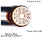
본 발명은 탈출수핵 분해를 통한 허리통증 감소를 위한 최소침습성 플라즈마 생성전극에 관한 것이다. 도1은 종래에 외과수술에 사용되던 전극의 사진이다. 종래의 전극은 사용되는 용량이나 대상물질의 부피에 따라 여러 종류의 것이 사용되었는데 도1은 대용량의 전극으로 큰 부피의 대상물질을 빠르게 분해하기 위한 것이다. 이러한 전극은 무릎이나 팔꿈지 같은 관절내시경 수술을 할때 대상 부위에 물을 채워 불필요한 이물질을 제거해 내는데 이러한 전극을 사용하면 물이 차있는 상태에서도 수술후 바로 지혈이 가능해지기 때문에 회복도 그만큼 빨라지게 된다. 따라서 이러한 전극은 최근 그 사용도가 매우 높아지고 있다. 이를 위하여 종래에 사용되는 전극은 약 3.5mm 정도의 지름에 다수개의 작은 티타늄 전극을 생성하고 후방에 스테인레스(SUS) 전극을 생성하고 다수개의 티타늄전극은 세라믹 스페이서로 간격을 설정하고 한두개의 원을 그리며 형성되도록 한다.The present invention relates to a minimally invasive plasma generating electrode for reducing back pain through prolapse nucleus disintegration. 1 is a photograph of an electrode conventionally used in surgical operations. Conventional electrodes have been used in a variety of types depending on the capacity or volume of the target material used in Figure 1 is to rapidly decompose a large volume of the target material with a large-capacity electrode. These electrodes are filled with water to remove unnecessary foreign objects when performing joint endoscopy such as knee or elbow. Using these electrodes, hemostasis is possible immediately after surgery, even when the water is full, so the recovery is faster. Therefore, these electrodes have recently been used very high. For this purpose, a conventional electrode generates a plurality of small titanium electrodes with a diameter of about 3.5 mm, a stainless steel (SUS) electrode at the rear, and a plurality of titanium electrodes are spaced with ceramic spacers and draws one or two circles. To form.
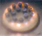
그런데 이러한 종래의 전극은 티타늄전극에는 모두 동일한 전압이 걸리고 SUS 전극에는 티타늄 전극과 반대극성의 전압이 걸리게 되는데 도2와 같이 안쪽 전극에는 플라즈마가 발생하지 않으면서 대부분의 플라즈마가 바깥쪽에서 발생하게 된다. 즉, 이것 때문에 전극의 크기를 최소화하는데 한계가 있을 수 밖에 없으며 작은 부위에 사용하기에 어려움이 생길 수 밖에 없다.However, these conventional electrodes are all applied with the same voltage to the titanium electrode and the voltage of opposite polarity to that of the titanium electrode to the SUS electrode. As shown in FIG. 2, most of the plasma is generated outside the plasma without generating the plasma at the inner electrode. That is, because of this, there is a limit to minimizing the size of the electrode, it is inevitable to use in small areas.
또한, 이러한 전극을 탈출수핵분해에 사용하는 경우 기존에는 열을 이용하여 시술함으로써 온도상승에 의한 세포조직의 탄화가 많이 일어 나는 단점이 있었으며 기존의 전극은 시술할 때 유전체상의 구멍으로 인체조직이 스며드는 것을 막을 수 없는 단점이 있었다.
In addition, when the electrode is used for escape nucleation, conventionally, heat treatment is performed using heat to cause a lot of carbonization of the cell tissue due to the temperature rise. Existing electrodes are infiltrated into the pores on the dielectric during the procedure. There was a disadvantage that can not be prevented.
본 발명은 상기한 바와 같은 단점을 극복하기 위하여 안출된것으로서 전극의 크기를 최소화하면서도 더나은 성능을 낼 수 있으며 유전체상의 구멍으로 인체조직이 스며드는 것을 막는 효과를 가진 플라즈마 생성전극을 제공하는 것을 목적으로 한다.An object of the present invention is to provide a plasma generating electrode having the effect of minimizing the size of the electrode to achieve better performance and to prevent the penetration of human tissue into the pores on the dielectric to overcome the disadvantages described above. do.
상기한 바와 같은 목적을 달성하기 위하여 최소침습성 플라즈마 생성전극을 제공하는데 상기 전극은, 봉형태의 플라즈마 전극과;상기 전극이 삽입되는 전극결합부가 관통하여 하나이상 형성되고 후면에는 후방전극결합부가 형성이 되며 상기 전극결합부의 전면은 상기 플라즈마전극의 굵기와 차이가 없으나 후면은 상기 플라즈마전극의 굵기보다 큰 유전체와; 상기 전극결합부의 후면과 맞닿는 곳에 전극관통부가 형성이 되며 전면으로 후방전극돌출부가 형성이 되어 상기 후방전극돌출부는 상기 유전체에 형성된 후방전극결합부에 삽입결합되는 후방전극;을 포함할 수 있다.In order to achieve the above object, a minimally invasive plasma generating electrode is provided, wherein the electrode includes a rod-shaped plasma electrode; at least one penetrating electrode coupling portion into which the electrode is inserted is formed, and a rear electrode coupling portion is formed on the rear surface thereof. A front surface of the electrode coupling part is not different from a thickness of the plasma electrode, but a rear surface of the electrode is larger than the thickness of the plasma electrode; An electrode through portion may be formed in contact with a rear surface of the electrode coupling portion, and a rear electrode protrusion may be formed on the front surface, such that the rear electrode protrusion is inserted into and coupled to the rear electrode coupling portion formed on the dielectric.
상기 전극결합부는 원형을 이루며 형성이 되며 등간격으로 형성이 되며 한 개건너 한 개 플라즈마전극마다 극성이 교차되어 인가되며 상기 후방전극은 접지되는 것일 수 있다. The electrode coupling part may be formed in a circular shape, and may be formed at equal intervals, and the polarity may be applied alternately for each plasma electrode one by one, and the rear electrode may be grounded.
상기 전극간 거리는 0.6mm 이하이며 상기 플라즈마생성전극의 굵기는 2.5mm 이하인 것일 수 있다. The distance between the electrodes is 0.6mm or less and the thickness of the plasma generating electrode may be 2.5mm or less.
상기 플라즈마전극은 텅스텐이며 유전체와 플라즈마전극 사이는 밀착되어 인체조직이 스며드는 것을 막는 것일 수 있다. The plasma electrode is tungsten and may be in close contact with the dielectric and the plasma electrode to prevent human tissue from infiltrating.
상기 플라즈마 전극의 수는 6개 이상일 수 있으며, 복수의 짝수개로 서로 짝을 이루고 있을 수 있다. The number of plasma electrodes may be six or more, and may be paired with a plurality of even numbers.
본 발명은 전극의 크기를 최소화하면서도 더나은 성능을 낼 수 있으며 유전체상의 구멍으로 인체조직이 스며드는 것을 막는 효과를 가진다.The present invention can produce better performance while minimizing the size of the electrode and has the effect of preventing human tissue from penetrating into the pores on the dielectric.
도1,2는 종래의 전극을 도시하는 도면
도3내지7은 본 발명에 따른 전극을 도시하는 도면1 and 2 show a conventional electrode.
3 to 7 show an electrode according to the present invention.
이하 첨부한 도면을 참고로 하여 본 발명을 상세하게 설명한다. 도3내지 도5는 각각 플라즈마 발생전극,유전체, 후방전극을 도시한 도면이며 도6은 플라즈마 발생전극, 유전체, 후방전극이 모두 결합된 형태를 도시한다. 플라즈마발생전극(11)은 텅스텐으로 형성되며 섭씨 300도 정도의 녹는점을 가지며 0.2파이 정도의 두께를 갖는다. 그러나 여기서 제시하는 수치는 일실시예에 불과할 뿐이며 이에 제한되지는 않는다. 도4는 유전체(12)를 도시하는데 본 실시예에서는 강한 내열성을 갖는 알루미나를 사용하였다. 유전체는 안쪽에 후방전극이 결합하는 후방전극결합부(13)가 있으며 플라즈마발생전극(11)이 결합하는 전극결합부(14)가 형성되어 있다. 전극결합부(14)는 유전체를 관통하여 형성되며 세포조직과 닿는 부분의 직경은 플라즈마전극의 직경과 거의 같도록 하여 세포조직이 스며드는 것을 방지한다. 본 실시예에서 플라즈마전극(11)은 6개가 사용되기 때문에 유전체에도 6개의 전극결합부(14)가 형성된다. 유전체는 플라즈마 발생전극간을 전기적으로 단절시키도록 하며 텅스텐으로 이루어진 플라즈마 전극은 플라즈마를 생성하는데 사용된다.DETAILED DESCRIPTION OF THE PREFERRED EMBODIMENTS The present invention will now be described in detail with reference to the accompanying drawings. 3 to 5 show a plasma generating electrode, a dielectric, and a rear electrode, respectively, and FIG. 6 shows a form in which the plasma generating electrode, the dielectric, and the rear electrode are all combined. The
도5는 후방전극을 도시한다. 후방전극(15)은 양쪽 끝이 돌출된 형태이며 한쪽 끝은 후방전극결합부(13)에 삽입되어 결합이 된다. 또한 전극관통부(16)가 형성되어 플라즈마 발생전극(11)이 관통될 수 있도록 한다. 도6은 이러한 결합의 예를 도시한다. 후방전극(15)은 플라즈마 발생전극에서 전류를 회수하여 전류경로를 집중시키는데 사용된다.
5 shows the rear electrode. The
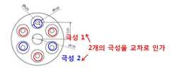
도7은 플라즈마 전극에 극성이 인가되는 예를 도시하는데 본 실시예에서는 6개의 플라즈마전극이 사용되는데 전극간 거리는 약 0.6mm 이며 기존의 전극이 직경 3.5mm 이상인것에 반해 본 발명에 따른 전극은 약 0.2파이의 플라즈마전극을 6개만 사용하기 때문에 2.5mm 정도의 직경만을 갖는다. 또한 플라즈마 전극을 3개씩 짝지워 플라즈마 전극마다 극성이 교차로 인가되도록 한다. 이처럼 전극을 교차하여 인가하기 때문에 각각의 전극간의 전위차가 최대화되어 플라즈마 전력을 증대화 할 수 있다. 기존전극은 전방의 플라즈마 발생전극과 후방의 전극간의 전기장으로 플라즈마를 생성하지만 본 발명에서는 전극간의 전압차를 최대화하고 전극간의 방전을 통하여 플라즈마 전극간의 거리를 감소시켜 전기장을 증가시킴으로써 플라즈마 생성량을 증가시켰으며 전체 전극의 크기를 2.5mm로 제한하는데 성공하였으며 특히 툴출수핵분해 시술에서 시술대상인 수핵으로의 접근을 위해서는 주변 섬유륜 조직을 통과하기 위하여는 굵기 3mm 이하의 전극을 사용하여야만 섬유륜조직의 기계적 손상없이 접근이 가능한데 본 발명에서는 2.5mm 이하의 전극을 사용함으로써 이러한 목적을 달성할 수 있다. 한편, 현재 사용되는 기존의 전극은 대용량인 경우 약 5mm 를 넘어가기 때문에 접근과정에서 섬유륜이 파손됨으로써 재발가능성이 높아지며 염증발생가능성이 높아진다.
FIG. 7 shows an example in which polarity is applied to the plasma electrode. In this embodiment, six plasma electrodes are used. The distance between the electrodes is about 0.6 mm and the electrode according to the present invention is about 0.2 mm in diameter, whereas the existing electrode is about 0.2 mm or more. Since only 6 plasma electrodes are used, it has a diameter of about 2.5 mm. In addition, three plasma electrodes are paired with each other so that polarities are alternately applied to the plasma electrodes. In this way, the potential difference between each electrode is maximized because the electrodes are crossed to each other, thereby increasing plasma power. The existing electrode generates plasma by the electric field between the front plasma generating electrode and the rear electrode, but in the present invention, the plasma generation amount is increased by maximizing the voltage difference between the electrodes and increasing the electric field by decreasing the distance between the plasma electrodes through the discharge between the electrodes. In addition, it has succeeded in limiting the size of the entire electrode to 2.5mm. Especially, in order to access the nucleus of the nucleus from the tool nucleus hydrolysis, the electrode of less than 3mm thick must be used to pass through the surrounding annulus tissue without mechanical damage to the annulus. In the present invention, the object can be achieved by using an electrode of 2.5 mm or less. On the other hand, the existing electrode currently used is about 5mm in the case of a large capacity, so that the possibility of recurrence is increased by the breakage of the annulus in the approach process, and the probability of inflammation increases.
또한, 플라즈마는 기포막 내부에서 형성되는데 전극간의거리가 멀어질 경우 전극에서 형성된 기포막이 하나로 합쳐지며 전극간의 직접적인 방전현상으로 인체에 가해지는 열손상을 감소시키고 분해율을 증가시킨다. 또한 기포막이 텅스텐 전극표면에서 개별적으로 생성될 수 있도록 전극간의 간격을 조절하는 것이 가능하다.
In addition, the plasma is formed inside the bubble film. When the distance between the electrodes increases, the bubble films formed on the electrodes merge into one, and the direct discharge phenomenon between the electrodes reduces heat damage to the human body and increases the decomposition rate. It is also possible to adjust the spacing between the electrodes so that the bubble film can be produced separately on the tungsten electrode surface.
11: 플라즈마발생전극12: 유전체
13: 후방전극결합부14: 전극결합부
15: 후방전극16: 전극관통부
17: 후방전극돌출부11: plasma generating electrode 12: dielectric
13: rear electrode coupling 14: electrode coupling
15: rear electrode 16: electrode through part
17: rear electrode projection
Claims (5)
Translated fromKorean봉형태의 플라즈마 전극과;
상기 전극이 삽입되는 전극결합부가 관통하여 하나이상 형성되고 후면에는 후방전극결합부가 형성이 되며 상기 전극결합부의 전면은 상기 플라즈마전극의 굵기와 차이가 없으나 후면은 상기 플라즈마전극의 굵기보다 큰 유전체와;
상기 전극결합부의 후면과 맞닿는 곳에 전극관통부가 형성이 되며 전면으로 후방전극돌출부가 형성이 되어 상기 후방전극돌출부는 상기 유전체에 형성된 후방전극결합부에 삽입결합되는 후방전극;을 포함하며 상기 전극결합부는 원형을 이루며 형성이 되며 등간격으로 형성이 되며 한 개건너 한 개 플라즈마전극마다 극성이 교차되어 인가되며 상기 후방전극은 접지되는, 최소침습성 플라즈마 생성전극
As a minimally invasive plasma generating electrode,
A rod-shaped plasma electrode;
At least one electrode coupling portion through which the electrode is inserted and a rear electrode coupling portion are formed at a rear surface thereof, and a front surface of the electrode coupling portion is not different from a thickness of the plasma electrode, but a rear surface of the dielectric is larger than the thickness of the plasma electrode;
An electrode through portion is formed in contact with a rear surface of the electrode coupling portion and a rear electrode protrusion is formed on the front surface so that the rear electrode protrusion is inserted into and coupled to the rear electrode coupling portion formed on the dielectric; and the electrode coupling portion Minimally invasive plasma generating electrode which is formed in a circular shape, is formed at equal intervals, and is applied with the polarity crossing every one and every plasma electrode, and the rear electrode is grounded.
5. The minimally invasive plasma generating electrode as recited in claim 4, wherein the number of plasma electrodes is six.
Priority Applications (1)
| Application Number | Priority Date | Filing Date | Title |
|---|---|---|---|
| KR1020110001927AKR101248105B1 (en) | 2011-01-07 | 2011-01-07 | Structure of Miniature Invasice Multi-pole Plasma Generation Electrode for the Ablation of Herniated Nucleus Pulposus |
Applications Claiming Priority (1)
| Application Number | Priority Date | Filing Date | Title |
|---|---|---|---|
| KR1020110001927AKR101248105B1 (en) | 2011-01-07 | 2011-01-07 | Structure of Miniature Invasice Multi-pole Plasma Generation Electrode for the Ablation of Herniated Nucleus Pulposus |
Publications (2)
| Publication Number | Publication Date |
|---|---|
| KR20120080450A KR20120080450A (en) | 2012-07-17 |
| KR101248105B1true KR101248105B1 (en) | 2013-03-27 |
Family
ID=46713056
Family Applications (1)
| Application Number | Title | Priority Date | Filing Date |
|---|---|---|---|
| KR1020110001927AExpired - Fee RelatedKR101248105B1 (en) | 2011-01-07 | 2011-01-07 | Structure of Miniature Invasice Multi-pole Plasma Generation Electrode for the Ablation of Herniated Nucleus Pulposus |
Country Status (1)
| Country | Link |
|---|---|
| KR (1) | KR101248105B1 (en) |
Citations (4)
| Publication number | Priority date | Publication date | Assignee | Title |
|---|---|---|---|---|
| JP2006501016A (en) | 2002-10-04 | 2006-01-12 | プラズマ サージカル インベストメンツ リミテッド | Plasma surgical device |
| JP2006210178A (en)* | 2005-01-28 | 2006-08-10 | Ngk Insulators Ltd | Electrode device for plasma generation |
| JP2010033914A (en) | 2008-07-29 | 2010-02-12 | Kyocera Corp | Dielectric structure, and discharge device and fluid reformer using the same |
| KR20100058755A (en)* | 2008-11-25 | 2010-06-04 | 포항공과대학교 산학협력단 | Cold surface plasma device for sterilization of bacteria |
- 2011
- 2011-01-07KRKR1020110001927Apatent/KR101248105B1/ennot_activeExpired - Fee Related
Patent Citations (4)
| Publication number | Priority date | Publication date | Assignee | Title |
|---|---|---|---|---|
| JP2006501016A (en) | 2002-10-04 | 2006-01-12 | プラズマ サージカル インベストメンツ リミテッド | Plasma surgical device |
| JP2006210178A (en)* | 2005-01-28 | 2006-08-10 | Ngk Insulators Ltd | Electrode device for plasma generation |
| JP2010033914A (en) | 2008-07-29 | 2010-02-12 | Kyocera Corp | Dielectric structure, and discharge device and fluid reformer using the same |
| KR20100058755A (en)* | 2008-11-25 | 2010-06-04 | 포항공과대학교 산학협력단 | Cold surface plasma device for sterilization of bacteria |
Also Published As
| Publication number | Publication date |
|---|---|
| KR20120080450A (en) | 2012-07-17 |
Similar Documents
| Publication | Publication Date | Title |
|---|---|---|
| US20240138900A1 (en) | Systems and methods systems related to electrosurgical wands with screen electrodes | |
| ES2654517T3 (en) | Electrosurgical Needle Apparatus | |
| ES2749712T3 (en) | Self-heating electric syringe plug / needle for use in filling a root canal | |
| CN111643176A (en) | Radio frequency ablation electrode for otitis media minimally invasive surgery and using method thereof | |
| US20140314621A1 (en) | Methods and devices for treating surfaces with surface plasma | |
| JP5441051B2 (en) | Plasma irradiation device | |
| US20130090644A1 (en) | Electrosurgical apparatus and system | |
| US8986299B2 (en) | Ablator with scalloped electrode and swaged tube | |
| KR101629555B1 (en) | Dermatophytosis treatment device using plasma source | |
| CN115024813B (en) | Plasma electrode assembly | |
| CN107456272A (en) | A kind of plasma external piles scalpel | |
| CN113069201A (en) | Multipolar electroporation ablation needle and electroporation ablation apparatus using the same | |
| KR101248105B1 (en) | Structure of Miniature Invasice Multi-pole Plasma Generation Electrode for the Ablation of Herniated Nucleus Pulposus | |
| JP2005080988A (en) | Crymotherapy apparatus and heat conducting needle means | |
| US6616656B2 (en) | Two-electrode endoscopic implement | |
| JP2025098272A (en) | Cryoballoon catheter with heating function | |
| ES2458515T3 (en) | Cathode assembly and pulsed plasma generation method | |
| JP2013163019A (en) | Electrode tip for high frequency surgery and electrode for high frequency surgery including the same | |
| JP2004305735A (en) | Machine expansion type helical freezing chip for freeze-cutting catheter | |
| JP5937936B2 (en) | Manufacturing method and manufacturing apparatus for medical and sanitary instruments provided with sharp part | |
| CN110236666A (en) | A kind of backbone percutaneous puncture plasma surgical knif head and its operating method | |
| KR200379423Y1 (en) | Shock Wave Generator of Extracorporeal Shock Wave Lithotripsy | |
| CN211460490U (en) | Safe type plasma operation electrode | |
| CN217408962U (en) | Radio frequency and low temperature plasma operation electrode | |
| US20200085490A1 (en) | High-frequency thermal therapy device |
Legal Events
| Date | Code | Title | Description |
|---|---|---|---|
| A201 | Request for examination | ||
| PA0109 | Patent application | St.27 status event code:A-0-1-A10-A12-nap-PA0109 | |
| PA0201 | Request for examination | St.27 status event code:A-1-2-D10-D11-exm-PA0201 | |
| P11-X000 | Amendment of application requested | St.27 status event code:A-2-2-P10-P11-nap-X000 | |
| P13-X000 | Application amended | St.27 status event code:A-2-2-P10-P13-nap-X000 | |
| P11-X000 | Amendment of application requested | St.27 status event code:A-2-2-P10-P11-nap-X000 | |
| P13-X000 | Application amended | St.27 status event code:A-2-2-P10-P13-nap-X000 | |
| P11-X000 | Amendment of application requested | St.27 status event code:A-2-2-P10-P11-nap-X000 | |
| P13-X000 | Application amended | St.27 status event code:A-2-2-P10-P13-nap-X000 | |
| R15-X000 | Change to inventor requested | St.27 status event code:A-3-3-R10-R15-oth-X000 | |
| R16-X000 | Change to inventor recorded | St.27 status event code:A-3-3-R10-R16-oth-X000 | |
| PN2301 | Change of applicant | St.27 status event code:A-3-3-R10-R11-asn-PN2301 St.27 status event code:A-3-3-R10-R13-asn-PN2301 | |
| D13-X000 | Search requested | St.27 status event code:A-1-2-D10-D13-srh-X000 | |
| D14-X000 | Search report completed | St.27 status event code:A-1-2-D10-D14-srh-X000 | |
| E902 | Notification of reason for refusal | ||
| PE0902 | Notice of grounds for rejection | St.27 status event code:A-1-2-D10-D21-exm-PE0902 | |
| PG1501 | Laying open of application | St.27 status event code:A-1-1-Q10-Q12-nap-PG1501 | |
| E13-X000 | Pre-grant limitation requested | St.27 status event code:A-2-3-E10-E13-lim-X000 | |
| P11-X000 | Amendment of application requested | St.27 status event code:A-2-2-P10-P11-nap-X000 | |
| P13-X000 | Application amended | St.27 status event code:A-2-2-P10-P13-nap-X000 | |
| E701 | Decision to grant or registration of patent right | ||
| PE0701 | Decision of registration | St.27 status event code:A-1-2-D10-D22-exm-PE0701 | |
| R18-X000 | Changes to party contact information recorded | St.27 status event code:A-3-3-R10-R18-oth-X000 | |
| GRNT | Written decision to grant | ||
| PR0701 | Registration of establishment | St.27 status event code:A-2-4-F10-F11-exm-PR0701 | |
| PR1002 | Payment of registration fee | Fee payment year number:1 St.27 status event code:A-2-2-U10-U11-oth-PR1002 | |
| PG1601 | Publication of registration | St.27 status event code:A-4-4-Q10-Q13-nap-PG1601 | |
| PN2301 | Change of applicant | St.27 status event code:A-5-5-R10-R11-asn-PN2301 St.27 status event code:A-5-5-R10-R13-asn-PN2301 | |
| PN2301 | Change of applicant | St.27 status event code:A-5-5-R10-R11-asn-PN2301 St.27 status event code:A-5-5-R10-R13-asn-PN2301 | |
| FPAY | Annual fee payment | Payment date:20160122 Year of fee payment:4 | |
| PR1001 | Payment of annual fee | Fee payment year number:4 St.27 status event code:A-4-4-U10-U11-oth-PR1001 | |
| FPAY | Annual fee payment | Payment date:20170224 Year of fee payment:5 | |
| PR1001 | Payment of annual fee | Fee payment year number:5 St.27 status event code:A-4-4-U10-U11-oth-PR1001 | |
| P22-X000 | Classification modified | St.27 status event code:A-4-4-P10-P22-nap-X000 | |
| FPAY | Annual fee payment | Payment date:20180222 Year of fee payment:6 | |
| PR1001 | Payment of annual fee | Fee payment year number:6 St.27 status event code:A-4-4-U10-U11-oth-PR1001 | |
| LAPS | Lapse due to unpaid annual fee | ||
| PC1903 | Unpaid annual fee | Not in force date:20190322 Payment event data comment text:Termination Category : DEFAULT_OF_REGISTRATION_FEE St.27 status event code:A-4-4-U10-U13-oth-PC1903 | |
| R18-X000 | Changes to party contact information recorded | St.27 status event code:A-5-5-R10-R18-oth-X000 | |
| R18-X000 | Changes to party contact information recorded | St.27 status event code:A-5-5-R10-R18-oth-X000 | |
| PN2301 | Change of applicant | St.27 status event code:A-5-5-R10-R11-asn-PN2301 St.27 status event code:A-5-5-R10-R13-asn-PN2301 | |
| PC1903 | Unpaid annual fee | Ip right cessation event data comment text:Termination Category : DEFAULT_OF_REGISTRATION_FEE Not in force date:20190322 St.27 status event code:N-4-6-H10-H13-oth-PC1903 | |
| PN2301 | Change of applicant | St.27 status event code:A-5-5-R10-R11-asn-PN2301 St.27 status event code:A-5-5-R10-R13-asn-PN2301 | |
| R18-X000 | Changes to party contact information recorded | St.27 status event code:A-5-5-R10-R18-oth-X000 | |
| R18-X000 | Changes to party contact information recorded | St.27 status event code:A-5-5-R10-R18-oth-X000 | |
| R18-X000 | Changes to party contact information recorded | St.27 status event code:A-5-5-R10-R18-oth-X000 | |
| R18-X000 | Changes to party contact information recorded | St.27 status event code:A-5-5-R10-R18-oth-X000 | |
| R18-X000 | Changes to party contact information recorded | St.27 status event code:A-5-5-R10-R18-oth-X000 | |
| R18-X000 | Changes to party contact information recorded | St.27 status event code:A-5-5-R10-R18-oth-X000 |