KR101246992B1 - Bottle container, bottle, and screw forming device - Google Patents
Bottle container, bottle, and screw forming deviceDownload PDFInfo
- Publication number
- KR101246992B1 KR101246992B1KR1020117004807AKR20117004807AKR101246992B1KR 101246992 B1KR101246992 B1KR 101246992B1KR 1020117004807 AKR1020117004807 AKR 1020117004807AKR 20117004807 AKR20117004807 AKR 20117004807AKR 101246992 B1KR101246992 B1KR 101246992B1
- Authority
- KR
- South Korea
- Prior art keywords
- screw
- cap
- neck
- bottle container
- thread
- Prior art date
- Legal status (The legal status is an assumption and is not a legal conclusion. Google has not performed a legal analysis and makes no representation as to the accuracy of the status listed.)
- Expired - Lifetime
Links
Images


Classifications
- B—PERFORMING OPERATIONS; TRANSPORTING
- B65—CONVEYING; PACKING; STORING; HANDLING THIN OR FILAMENTARY MATERIAL
- B65D—CONTAINERS FOR STORAGE OR TRANSPORT OF ARTICLES OR MATERIALS, e.g. BAGS, BARRELS, BOTTLES, BOXES, CANS, CARTONS, CRATES, DRUMS, JARS, TANKS, HOPPERS, FORWARDING CONTAINERS; ACCESSORIES, CLOSURES, OR FITTINGS THEREFOR; PACKAGING ELEMENTS; PACKAGES
- B65D1/00—Rigid or semi-rigid containers having bodies formed in one piece, e.g. by casting metallic material, by moulding plastics, by blowing vitreous material, by throwing ceramic material, by moulding pulped fibrous material or by deep-drawing operations performed on sheet material
- B65D1/02—Bottles or similar containers with necks or like restricted apertures, designed for pouring contents
- B65D1/0223—Bottles or similar containers with necks or like restricted apertures, designed for pouring contents characterised by shape
- B65D1/023—Neck construction
- B65D1/0246—Closure retaining means, e.g. beads, screw-threads
- B—PERFORMING OPERATIONS; TRANSPORTING
- B21—MECHANICAL METAL-WORKING WITHOUT ESSENTIALLY REMOVING MATERIAL; PUNCHING METAL
- B21D—WORKING OR PROCESSING OF SHEET METAL OR METAL TUBES, RODS OR PROFILES WITHOUT ESSENTIALLY REMOVING MATERIAL; PUNCHING METAL
- B21D51/00—Making hollow objects
- B21D51/16—Making hollow objects characterised by the use of the objects
- B21D51/38—Making inlet or outlet arrangements of cans, tins, baths, bottles, or other vessels; Making can ends; Making closures
- B—PERFORMING OPERATIONS; TRANSPORTING
- B65—CONVEYING; PACKING; STORING; HANDLING THIN OR FILAMENTARY MATERIAL
- B65D—CONTAINERS FOR STORAGE OR TRANSPORT OF ARTICLES OR MATERIALS, e.g. BAGS, BARRELS, BOTTLES, BOXES, CANS, CARTONS, CRATES, DRUMS, JARS, TANKS, HOPPERS, FORWARDING CONTAINERS; ACCESSORIES, CLOSURES, OR FITTINGS THEREFOR; PACKAGING ELEMENTS; PACKAGES
- B65D41/00—Caps, e.g. crown caps or crown seals, i.e. members having parts arranged for engagement with the external periphery of a neck or wall defining a pouring opening or discharge aperture; Protective cap-like covers for closure members, e.g. decorative covers of metal foil or paper
- B65D41/02—Caps or cap-like covers without lines of weakness, tearing strips, tags, or like opening or removal devices
- B65D41/04—Threaded or like caps or cap-like covers secured by rotation
- B—PERFORMING OPERATIONS; TRANSPORTING
- B65—CONVEYING; PACKING; STORING; HANDLING THIN OR FILAMENTARY MATERIAL
- B65D—CONTAINERS FOR STORAGE OR TRANSPORT OF ARTICLES OR MATERIALS, e.g. BAGS, BARRELS, BOTTLES, BOXES, CANS, CARTONS, CRATES, DRUMS, JARS, TANKS, HOPPERS, FORWARDING CONTAINERS; ACCESSORIES, CLOSURES, OR FITTINGS THEREFOR; PACKAGING ELEMENTS; PACKAGES
- B65D41/00—Caps, e.g. crown caps or crown seals, i.e. members having parts arranged for engagement with the external periphery of a neck or wall defining a pouring opening or discharge aperture; Protective cap-like covers for closure members, e.g. decorative covers of metal foil or paper
- B65D41/32—Caps or cap-like covers with lines of weakness, tearing-strips, tags, or like opening or removal devices, e.g. to facilitate formation of pouring openings
- B65D41/34—Threaded or like caps or cap-like covers provided with tamper elements formed in, or attached to, the closure skirt
- B65D41/3442—Threaded or like caps or cap-like covers provided with tamper elements formed in, or attached to, the closure skirt with rigid bead or projections formed on the tamper element and coacting with bead or projections on the container
- B65D41/3447—Threaded or like caps or cap-like covers provided with tamper elements formed in, or attached to, the closure skirt with rigid bead or projections formed on the tamper element and coacting with bead or projections on the container the tamper element being integrally connected to the closure by means of bridges
- B—PERFORMING OPERATIONS; TRANSPORTING
- B67—OPENING, CLOSING OR CLEANING BOTTLES, JARS OR SIMILAR CONTAINERS; LIQUID HANDLING
- B67B—APPLYING CLOSURE MEMBERS TO BOTTLES JARS, OR SIMILAR CONTAINERS; OPENING CLOSED CONTAINERS
- B67B3/00—Closing bottles, jars or similar containers by applying caps
- B67B3/02—Closing bottles, jars or similar containers by applying caps by applying flanged caps, e.g. crown caps, and securing by deformation of flanges
- B67B3/10—Capping heads for securing caps
- B67B3/18—Capping heads for securing caps characterised by being rotatable, e.g. for forming screw threads in situ
- Y—GENERAL TAGGING OF NEW TECHNOLOGICAL DEVELOPMENTS; GENERAL TAGGING OF CROSS-SECTIONAL TECHNOLOGIES SPANNING OVER SEVERAL SECTIONS OF THE IPC; TECHNICAL SUBJECTS COVERED BY FORMER USPC CROSS-REFERENCE ART COLLECTIONS [XRACs] AND DIGESTS
- Y10—TECHNICAL SUBJECTS COVERED BY FORMER USPC
- Y10S—TECHNICAL SUBJECTS COVERED BY FORMER USPC CROSS-REFERENCE ART COLLECTIONS [XRACs] AND DIGESTS
- Y10S72/00—Metal deforming
- Y10S72/715—Method of making can bodies
Landscapes
- Engineering & Computer Science (AREA)
- Mechanical Engineering (AREA)
- Ceramic Engineering (AREA)
- Closures For Containers (AREA)
- Containers Having Bodies Formed In One Piece (AREA)
- Refuse Collection And Transfer (AREA)
- Making Paper Articles (AREA)
Abstract
Translated fromKoreanDescription
Translated fromKorean본 발명은, 목부에 나사부가 형성된 금속제 병 용기 및, 나사 성형 장치에 관한 것이다. 또 본 발명은, 목부 성형 방법에 관한 것이다.TECHNICAL FIELD This invention relates to the metal bottle container with a screw part provided in the neck part, and a screw shaping | molding apparatus. Moreover, this invention relates to the neck shaping | molding method.
금속제의 용기를 드로잉 가공하여 얻어지는 소위 병 용기 (1) 는, 바닥이 있는 통형상으로 형성된 병 용기 (1) 의 개구부에, 도 6a 에 나타내는 바와 같이 목부 (2) 와 그 외주에 형성된 나사부 (3) 를 갖는다. 이 나사부 (3) 에는, 병 용기 (1) 안에 음료수 등으로 이루어지는 제품이 충전된 후, 캡 (5) 의 외주가 나사부 (3) 를 따라서 가압 성형됨으로써 캡 (5) 이 도 6b 와 같이 피착된다. 캡 (5) 은, 병 용기 (1) 의 나사부 (3) 를 따라서 캡 나사부 (7) 가 형성되는 캡 본체 상부 (6) 와, 이 캡 본체 상부 (6) 의 하단에, 팽창돌출부 (4) 의 하면측으로 말려 들어가도록 형성되는 캡 본체 하부 (9) 로 이루어져 있다.The so-called
또한, 피착되기 전의 캡 (5) 은, 도 6c 에 나타낸 캡재 (5') 와 같은 형상으로 되어 있고, 상부가 천판(天板)에 의해 막히는 동시에, 그 하부가 하측을 향하여 일직선으로 개구된 통형상을 이루고 있다. 브리지부 (8) 는, 원주 방향으로 형성된 복수의 커팅선인 스코어 (8a) 와, 브리지 (8b) 가 교대로 배치되어 있고, 브리지부 (8) 를 통하여 캡 본체 하부 (9) 가 연결 형성되어 있다.In addition, the
캡 (5) 을 병 용기 (1) 로부터 떼어낼 때에는 캡 (5) 과 병 용기 (1) 에 상대 회전 방향의 회전력을 가한다. 이 회전력은 나사부 (3) 에 의해 캡 (5) 이 상측 방향으로 이동하도록 작용한다. 그러나, 캡 본체 하부 (9) 는 병 용기 (1) 의 팽창돌출부 (4) 에 걸려 고정되어 있기 때문에, 브리지 (8b) 가 파단되어 캡 본체 상부 (6) 와 캡 본체 하부 (9) 가 분리된다. 그리고, 캡 본체 하부 (9) 는 목부 (2) 에 남겨지고, 캡 본체 상부 (6) 는 병 용기 (1) 로부터 이탈된다. 즉, 이용자가 브리지부 (8) 를 파단하도록 캡 (5) 을 돌림으로써 병 용기 (1) 로부터 뚜껑을 열 수 있도록 되어 있다.When removing the
종래, 이러한 나사부 (3) 를 갖는 병 용기 (1) 는, 도 7a 에 나타내는 바닥이 있는 원통형상의 병 용기 (1) 의 개구부를, 도 7b 에 나타내는 바와 같이, 일단 직경을 축소시켜 목부 (2) 를 형성한 후, 도 7c 에 나타내는 바와 같이, 그 목부 (2) 의 개구단으로부터 소정 거리분만큼 다시 직경을 확장시켜 직경확장부 (2') 를 형성하고, 또 도 7d 에 나타내는 바와 같이, 개구단으로부터 일정한 거리에 나사부 (3) 를 형성함으로써, 나사부 (3) 가 형성되어 있지 않은 직경확장부분을 팽창돌출부 (4) 로서 남기는 것에 의해 팽창돌출부 (4) 를 형성하고 있다.Conventionally, the
도 6a∼도 6c 에 나타내고 있는, 병 용기 (1) 에 피착되어 있는 캡 (5) 의 외경 (A) 은, 일반적으로, 28㎜, 33㎜, 38㎜ 의 3 가지 규격이 존재하고 있다. 병 용기 (1) 의 목부 (2) 의 외경 (B) 은, 캡 (5) 의 외경 (A) 보다도 작게 형성된다. 나사부 (3) 는, 38㎜ 의 외경으로 이루어지는 캡 (5) 이 피착되는 경우, 나사로서 유효하게 기능하는 부분의 권수(卷數)인 유효 나사 권수가 1.5∼1.7 권 정도로 형성되어 있다.As for the outer diameter A of the
여기서, 유효 나사 권수란, 도 8 에 나타낸 유효 나사부 (X) 의 권수를 말한다. 도 8 은, 나사부 (3) 의 상면도를 간략하게 나타낸 설명도로서, Y, Z 가 불완전 나사부, W 가 완전 나사부이고, C 가 중심점이다. 나사부 (3) 는, 산부 (3a) 와 골부 (3b) 로 형성되어 있고, 목부 (2) 의 상단측에 시작측의 불완전 나사부 (Y) 가 형성되고, 목부 (2) 의 기단측에 종료측의 불완전 나사부 (Z) 가 형성되어 있다. 불완전 나사부 (Y) 와 불완전 나사부 (Z) 사이의 완전 나사부 (W) 는, 산부 (3a) 와 골부 (3b) 가 각각 규정된 외경으로 형성되어 있다. 불완전 나사부 (Y) 는, 그 단점(端点) (Y1) 으로부터 완전 나사부 (W) 의 시작점 (W1) 까지 서서히 나사산의 직경이 확장되고 있으며, 불완전 나사부 (Z) 는, 완전 나사부 (W) 의 종료점 (W2) 으로부터 그 단점 (Z2) 까지 서서히 나사 골의 직경이 확장된다.Here, the effective number of turns of thread means the number of turns of the effective screw portion X shown in FIG. 8. FIG. 8 is an explanatory view schematically showing a top view of the
유효 나사부 (X) 는, 불완전 나사부 (Y) 의 중간의 유효 나사 시작점 (X1) 으로부터 완전 나사부 (W) 전체를 포함하여, 불완전 나사부 (Z) 의 중간의 유효 나사 종료점 (X2) 까지의 나사부이다. 유효 나사 시작점 (X1) 은, 도 8 에 나타내는 나사부 (3) 의 상면에서 보았을 때의, 단점 (Y1) 과 중심점 (C) 과 시작점 (W1) 에 의해 만들어지는 불완전 나사부 (Y) 의 협각 (∠α) 의 2 등분선 (L1) 과 불완전 나사부 (Y) 와의 교점이고, 유효 나사 종료점 (X2) 은, 종료점 (W2) 과 중심점 (C) 과 단점 (Z2) 에 의해 만들어지는 불완전 나사부 (Z) 의 협각 (∠β) 의 2 등분선 (L2) 과 불완전 나사부 (Z) 와의 교점이다.The effective thread part X is a thread part from the effective screw start point X1 of the middle of the incomplete thread part Y to the effective screw end point X2 of the middle of the incomplete thread part Z, including the whole thread part W whole. . The effective screw starting point X1 is the narrow angle of the incomplete thread part Y formed by the disadvantage Y1, the center point C, and the starting point W1 when seen from the upper surface of the threaded
그런데, 종래의 병 용기 (1) 에 있어서, 병 용기 (1) 의 목부 (2) 에 형성되어 있는 나사부 (3) 의 유효 나사 권수가 1.5∼1.7 권 정도이면, 목부 (2) 의 기단부로부터 선단부를 향하여 나사가 2 개 있는 부분과, 나사가 1 개밖에 없는 부분이 생겨, 그 개수의 차에 따른 문제가 있었다. 즉, 상기 권수인 경우, 병 용기 (1) 에 캡 (5) 을 피착하고, 병 안을 양압(陽壓)으로 한 경우, 캡 (5) 을 밀어 올리는 압력이 가해져, 나사가 1 개 밖에 없는 부분에서는 캡 (5) 을 체결하는 힘이 약하여 캡 (5) 이 상측으로 어긋난다. 즉, 캡 (5) 이 병 용기 (1) 에 대하여 기울어 버리기 때문에, 나사가 1 개인 부분에서 브리지 (8b) 가 잡아 당겨져 파단된다. 소위 브리지 끊김이 일어난다는 문제가 있었다. 또한, 나사의 권수가 많은 부분에서는 적은 부분보다 캡 장착시에 나사부 (3) 의 압축되는 양이 커져, 이 때문에 둘레 방향에서의 시일성에 불균일이 발생하여 기밀성이 저하될 우려가 있었다.By the way, in the
이 대책으로서, 유효 나사 권수를 늘리는 것이 고려된다. 그런데, 병 용기 (1) 에 캡 (5) 을 피착시키는 공정에 있어서, 캡 직경이 28㎜ 정도의 작은 직경에서는 900N 정도의 하중으로 캡을 병에 밀어 누르면서 감아 조이는 것에 불과하지만, 캡 직경이 33㎜ 이상의 큰 직경인 경우에는, 용기 내의 압력이 캡 천장면을 밀어 올리는 힘이 강하고 성형 영역도 커지기 때문에, 압력 블록으로 1050∼1200N 의 힘으로 캡을 병 용기 천장면으로 밀어 누르면서 감아 조인다.As a countermeasure, increasing the effective number of screw turns is considered. By the way, in the process of adhering the
예를 들어, 유효 나사 권수를 2.5∼3 권으로 한 경우에는, 나사 개수가 2 개인 부분과 3 개인 부분이 형성되기 때문에, 전술한 바와 같은 캡 나사부 (7) 의 성형 공정에서, 나사 개수가 3 개인 부분이 2 개인 부분보다도 더 축선 방향으로 변형되기 쉬워진다. 그러면, 감아 조이는 중에 있어서는, 나사 형성 롤러의 캡 가압 위치와 완전 나사부 (W) 의 시작점 (W1) 의 상대 위치가 축선 방향으로 어긋나기 때문에, 나사 형성이 불충분한 부분이 생긴다. 또한, 나사 형성시에는, 캡 (5) 의 측면 하단측에 축선 방향 상측으로 끌어 올려지는 힘이 발생하기 때문에, 나사 개수가 많을수록 브리지는 끊어지기 쉬워진다. 따라서, 나사가 3 개인 부분이 지나치게 많을수록 브리지 끊김이 발생하기 쉬워진다. 그리고, 감아 조임 종료 후에서는, 압력 블록이 해방되면 나사 3 개 부분이 스프링이 되어 캡을 밀어 올리고자 하기 때문에, 나사 3 개측의 브리지가 2 개측의 브리지보다 끊어지기 쉬워진다. 또한, 권수를 3 권 이상으로 한 경우, 캡의 뚜껑을 여는 토크가 올라가고, 또한 거기에 필요한 회전수가 늘어나, 그 만큼 이용자의 뚜껑 열기 작업에 수고가 필요하므로 바람직하지 않다.For example, when the effective number of threads is 2.5 to 3, since the number of two screws and the number of three screws are formed, the number of screws is three in the forming process of the
또한, 병의 내압에 의해 캡 (5) 에 브리지 끊김이 발생하지 않은 경우라도, 캡 (5) 의 캡 나사부 (7) 와 천장면의 간격이 길면, 이 사이가 신장되어 캡 (5) 의 밀착성이 저하된다는 문제가 있었다. 또한, 캡 (5) 의 캡 나사부 (7) 와 천장면의 간격이 좁으면 캡 (5) 의 피착 공정에 있어서 캡 (5) 을 누르는 하중에 견딜 수 없어, 이 사이에 대응하는 목부 (2) 에 있어서 좌굴(座屈)이 발생한다는 문제가 있었다.In addition, even when the
또한 종래의 기술에 있어서는, 일반적으로, 음료용 용기으로서 널리 사용되고 있는 병 용기는, 알루미늄이나 알루미늄 합금제의 금속판을 드로잉 가공 (Drawing) 과, 이어서 실시되는 아이어닝 가공 (Ironing) 에 의해 형성되는, 일반적으로 DI 용기라고 불리고 있는 용기의 상부에, 목부가 형성되어 제조되고 있다. 이 병 용기에 내용물을 충전한 후, 병 용기의 목부에 캡이 피착되어, 캡이 부착되어 있는 병 용기가 된다.In the prior art, generally, a bottle container widely used as a beverage container is formed by drawing a metal plate made of aluminum or an aluminum alloy by ironing followed by ironing. The neck is formed and manufactured on the upper part of the container generally called a DI container. After the contents are filled in the bottle container, a cap is attached to the neck of the bottle container, and the bottle container with the cap is attached.
종래, 도 11 에 나타내는 바와 같은 캡이 부착된 병 용기 (101) 는, 병 용기 (102) 에 캡 (103) 이 피착되어 밀폐되어 있다. 병 용기 (102) 에 형성된 목부 (104) 에는, 수(雄) 나사부 (105) 와 팽창돌출부 (106) 와 컬(curl)부 (107) 가 형성되어 있다. 캡 (103) 에는, 천장면부 (108) 와 암(雌) 나사부 (109) 와 필퍼 프루프부 (110) 와 브리지부 (111) 가 형성되어 있고, 천장면부 (108) 의 내면에는 시일부재인 라이너 (112) 가 부착되어 있다. 병 용기 (102) 의 수 나사부 (105) 와 캡 (103) 의 암 나사부 (109) 를 끼워 맞춰, 팽창돌출부 (106) 의 하측으로 필퍼 프루프부 (110) 의 하단부가 말려 들어가는 상태로 캡 (103) 이 병 용기 (102) 에 피착되어 있고, 컬부 (107) 와 라이너 (112) 가 밀착됨으로써 밀봉되어 있다. 또한, 캡이 부착된 병 용기 (101) 는, 예를 들어 내용물이 탄산 음료인 경우 등, 규정된 내압에 견딜 수 있는 구조로 되어 있다.Conventionally, in the
캡이 부착된 병 용기 (101) 를 개봉할 때에는, 병 용기 (102) 에 대하여 캡 (103) 을 회전시키면, 암 나사부 (109) 가 수 나사부 (105) 로 안내되어 캡 (103) 을 상방으로 이동시키는 동시에, 팽창돌출부 (106) 와 필퍼 프루프부 (110) 의 걸어맞춤에 의해 브리지부 (111) 가 절단되고, 컬부 (107) 와 라이너 (112) 가 이간된다. 좀더 캡 (103) 을 회전시킴으로써 병 용기 (102) 로부터 캡 (103) 이 벗겨진다. 이렇게 뚜껑을 열기 위해 캡 (103) 을 회전시킬 때에, 캡 (103) 의 미끄러짐을 방지하고 지지성을 양호하게 하기 위해, 캡 (103) 에 널(knurl)부 (113) 가 형성되어 있다. 널부 (113) 는 암 나사부 (109) 의 상측에 형성되어 있고, 원주 방향에 형성된 단면이 원호형상인 돌출부에 주기적으로 오목부가 형성되어 이루어져 있다.When opening the
또한, 병 용기 (102) 에 캡 (103) 을 피착시키는 감아 조임 공정에 있어서, 암 나사부 (109) 및 필퍼 프루프부 (110) 가 형성되어 있지 않은 캡재를 병 용기 (102) 에 씌우고, 캡재를 병 용기 (102) 으로 밀어 누르는 방향으로 하중을 가하면서, 병 용기 (102) 의 수 나사부 (105) 및 팽창돌출부 (106) 의 형상을 따라서 암 나사부 (109) 및 필퍼 프루프부 (110) 가 형성된다. 이와 같이 하중을 가하면서 캡 (103) 이 감아 조여짐으로써, 컬부 (107) 와 라이너 (112) 와의 밀착성이 향상되어 양호하게 밀봉된다. 이 때, 수 나사부 (105) 및 암 나사부 (109) 의 유효 나사 권수는 1.5 내지 1.7 권 정도로 형성되어 있다.In addition, in the winding and tightening step of attaching the
그런데, 전술한 바와 같은 캡 (103) 이 피착된 병 용기 (102) 에 있어서 규정된 내압 이하의 압력이 캡 (103) 의 천장면부 (108) 에 가해진 경우라도, 캡 (103) 의 암 나사부 (109) 와 천장면부 (108) 의 사이가 길면, 이 사이가 신장되어 컬부 (107) 와 라이너 (112) 와의 밀착성이 저하된다는 문제가 있었다. 또한, 캡 (103) 의 암 나사부 (109) 와 천장면부 (108) 사이에는 널부 (113) 가 형성되어 있기 때문에, 추가로 신장되기 쉽다는 문제가 있었다.By the way, even when the pressure below the internal pressure prescribed | regulated in the
이러한 문제를 해결하기 위해, 캡 (103) 의 암 나사부 (109) 와 천장면부 (108) 와의 간격을 좁게 하는, 즉, 병 용기 (102) 의 수 나사부 (105) 로부터 컬부 (107) 의 상단면까지의 사이의 높이를 낮게 하는 방법이 있지만, 이 경우 캡 (103) 의 피착 공정에 있어서 캡 (103) 을 밀어 누르는 하중에 견디지 못하고, 좌굴된다는 문제가 있었다.To solve this problem, the gap between the female threaded
또한, 수 나사부 (105) 의 유효 나사 권수가 1.5 내지 1.7 권 정도이기 때문에, 목부 (104) 의 기단부로부터 선단부를 향하여 나사산이 1 개인 부분과 2 개인 부분이 생겨, 목부 (104) 의 둘레 방향에 걸쳐 수 나사부 (105) 와 암 나사부 (109) 와의 끼워 맞춰지는 힘이 일정치 않다는 문제가 있었다. 이것에 의해, 캡 (103) 을 피착시킨 병 용기 (102) 의 내압이 규정 내압 이하인 경우라도, 끼워 맞춰지는 힘이 약한 나사산이 1 개인 부분에 있어서 캡 (103) 이 상측으로 어긋나 컬부 (107) 와 라이너 (112) 와의 밀착성이 저하된다는 문제가 있었다. 또, 끼워 맞춰지는 힘을 높이기 위해 유효 나사 권수를 늘려 2.5 권 이상으로 한 경우, 개봉시의 토크가 커진다는 문제가 생긴다.In addition, since the effective number of threads of the
또한, 종래의 기술에 있어서는, 금속제의 용기를 드로잉 가공하여 얻어지는 소위 병 용기는, 바닥이 있는 통형상으로 형성된 병 용기의 개구부에 목부를 형성하고, 그 목부의 외주에 캡을 피착시키기 위한 나사부를 형성한다.In the related art, a so-called bottle container obtained by drawing a metal container is formed with a neck in an opening of a bottle container formed in a bottomed tubular shape, and a screw part for depositing a cap on the outer circumference of the neck. Form.
이러한 나사부를 갖는 병 용기를 제작하기 위해서는, 미리 바닥이 있는 원통형상의 병 용기가 형성되면, 그 병 용기의 개구부를, 도 19a 에 나타내는 바와 같이, 일단 직경을 축소시켜 목부 (202) 를 형성하고, 이어서, 그 목부 (202) 의 개구단으로부터 소정 거리만큼 직경을 확장시켜 도 19b 에 나타내는 바와 같이 직경확장부 (202') 를 형성한 후, 다시 나사 성형 장치에 의해 개구단으로부터 일정한 거리에 도 19c 와 같이 나사부 (203) 를 형성한다. 그 경우, 목부 (202) 에 나사부 (203) 를 형성했을 때, 나사부 (203) 가 형성되어 있지 않은 직경확장부분을 남기는 것에 의해 팽창돌출부 (204) 가 형성된다.In order to manufacture the bottle container which has such a screw part, when a cylindrical bottle container with a bottom is formed previously, as shown to FIG. 19A, the opening part of the bottle container is once reduced in diameter, and the
종래의 나사 성형 장치는, 도시를 생략했지만, 목부 (202) 의 내주면에 맞닿는 중자(中子)와, 목부 (202) 의 외주면에 맞닿는 외자(外子)가 서로 목부 (202) 를 사이에 끼워 넣고서 병 용기 (201) 의 축심 둘레를 회전함으로써, 목부 (202) 의 외주에 나사부 (203) 를 형성하도록 되어 있다. 이 경우, 목부 (202) 에 형성되는 나사부 (203) 의 권수로는, 도 19a∼도 19c 에 나타내는 바와 같이 약 1.7 권 정도로 되어 있다.In the conventional screw forming apparatus, although not shown in the drawings, a middle core that abuts against the inner circumferential surface of the
또한, 나사부 (203) 가 형성된 병 용기 (201) 는, 그 후, 목부 (202) 의 선단을 외측에서 내측으로 되꺾어 도 20 에 나타내는 바와 같이 컬부 (208) 를 형성하는 캡 피착 공정을 실시하는 등의 각종 공정을 거친 후, 내부에 내용물이 주입되면, 동 도에 나타내는 캡 (205) 이 피착되어 뚜껑이 닫힌다.In addition, the
전술한 바와 같이, 종래의 나사 성형 장치는, 병 용기 (201) 의 목부 (202) 의 내주면에 맞닿는 중자와, 목부 (202) 의 외주면에 맞닿는 외자가 서로 목부 (202) 를 사이에 끼워 넣고서 병 용기의 축심 둘레를 회전함으로써, 직경이 확장된 목부 (202) 에 1.7 권수로 이루어지는 나사부 (203) 를 형성하고 있다.As described above, in the conventional screw forming apparatus, the bottle which is in contact with the inner circumferential surface of the
그런데, 나사부의 권수가 1.7 권 정도이면, 도 20 에 나타내는 바와 같이, 목부 (202) 의 둘레면에서 나사부 (203) 가 2 개인 부분과 나사부 (203) 가 1 개뿐인 부분이 생겨, 그 개수의 차에 따른 문제가 있었다. 즉, 상기 권수인 경우, 병 용기 (201) 에 캡 (205) 을 피착시키고, 병 용기 (201) 안을 양압으로 한 경우, 캡 (205) 을 밀어 올리는 압력이 가해짐으로써 캡 (205) 이 상측으로 어긋나버린다. 이 때문에, 캡 (205) 이 병 용기 (201) 에 대하여 기울어지기 때문에, 캡 (205) 의 개구단측의 스코어 (206 와 206) 사이에 형성된 브리지 (207) 가 잡아 당겨져 파단되어, 소위 브리지 끊김이 일어나는 문제가 있었다.By the way, if the number of turns of the screw part is about 1.7, as shown in FIG. 20, the part which has two threaded
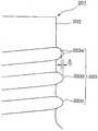
상기 문제를 해소하기 위해, 나사부 (203) 의 권수를 늘려, 도 21 과 같이 2.2 권으로 하는 방법이 시도되고 있다. 이와 같이 병 용기 (1) 의 목부 (202) 에 2.2 권의 나사부 (203) 를 형성하면, 나사부 (203) 의 나사 시작부 (203A) 에서 나사 종료부 (203B) 사이에서는, 나사부 (203) 가 제 1 단의 나사산 (203a) 과 제 2 단의 나사산 (203b) 과 제 3 단의 나사산 (203c) 과 같이 3 단으로 이루어지는 나사산 영역이 존재하게 된다.In order to solve the said problem, the method of increasing the number of turns of the
그런데, 병 용기 (201) 에 2.2 권의 나사부 (203) 를 형성했을 때, 전술한 바와 같은 3 단으로 이루어지는 나사산 영역이 형성되면, 그 후, 캡 피착 공정에 의해 목부 (202) 의 선단에 컬부 (208) 를 형성할 때, 캡 피착 장치가 목부 (202) 의 선단을 용기 바닥 방향으로 누르면서 컬부 (208) 를 형성한다.By the way, when the
그러나, 이 경우, 3 단으로 이루어지는 나사부 (203) 가 형성되어 있기 때문에, 제 1 단의 나사산 (203a) 과 컬부 (208) 와의 거리가 가까워, 캡 피착 공정시, 나사부 (203) 의 제 1 단의 나사산 (203a) 이 캡 피착 장치의 가압력에 의해 하측으로 가압되어 눌려 찌부러지게 되고, 이 때문에, 도 22 에 나타내는 바와 같이, 제 1 단의 나사산 (203a) 이 직경 방향으로 직경이 확장되어, 제 2 단의 나사산 (203b), 제 3 단의 나사산 (203c) 의 높이보다 치수 △ 분만큼 둘레 방향으로 돌출된다.However, in this case, since the
이와 같이 목부 (202) 의 제 1 단의 나사산 (203a) 이 둘레 방향으로 돌출된 상태에 있으면, 그 후, 뚜껑을 닫기 위해 캡 (205) 이 병 용기 (201) 에 피착된 경우에 캡 (205) 이 목부 (202) 의 형상에 따른 형상으로 피착되기 때문에, 도 22 에 나타내는 바와 같이, 캡 (205) 의 개구 직경이 병 나사산 (203a) 의 외경보다도 작아진다. 또, 캡 (205) 은 도 22 에서는 일부 파단된 상태로 나타내고 있다.Thus, if the
이러한 상태로 피착된 캡 (205) 은, 그 후, 이용자가 음료를 마시기 위해 병 용기 (201) 로부터 분리되고, 또한 음료 마시기를 중지하거나 할 때에 목부 (202) 를 닫는 일이 반복된다. 그런데, 캡 개구단측의 직경이 천판측의 직경보다 작게 되어 있으면, 이용자가 닫을 때에, 목부 (202) 와 캡 (205) 사이의 저항이 커서, 뚜껑을 닫기 위한 토크가 커지기 때문에, 취급에 지장을 초래하는 경우가 있었다.The
본 발명은, 이러한 사정을 고려하여 이루어진 것으로, 그 목적은, 병 용기의 목부에 피착된 캡에 브리지 끊김이 발생하지 않고, 캡을 양호하게 피착시킬 수 있는 병 용기 및 병 용기에 캡이 피착된 병을 제공하는 것이다.SUMMARY OF THE INVENTION The present invention has been made in view of such circumstances, and an object thereof is that a cap is attached to a bottle container and a bottle container capable of depositing the cap satisfactorily without a bridge break occurring on the cap deposited on the neck of the bottle container. To provide a bottle.
또한 본 발명은, 캡에 의해 금속제 병 용기의 목부를 확실히 밀봉할 수 있고, 좌굴 강도가 높은 금속제 병 용기를 제공하는 것을 목적으로 하고 있다.Moreover, an object of this invention is to provide the metal bottle container which can reliably seal the neck part of a metal bottle container by a cap, and has high buckling strength.
또, 본 발명의 목적은, 나사부의 권수를 늘리더라도, 캡 피착 공정에 상관없이 목부의 나사부를 모두 대략 균등하게 할 수 있는 병 용기의 목부 성형 방법을 제공하는 것이고, 다른 목적은, 상기 방법을 정확하게 실시할 수 있는 병 용기의 목부 성형 방법, 및 병 용기 그리고 병을 제공하는 것이다.Another object of the present invention is to provide a method for forming a neck of a bottle container in which the threads of the neck can be approximately equalized regardless of the cap deposition step, even if the number of turns of the thread is increased. To provide a neck molding method of a bottle container, and a bottle container and a bottle that can be accurately performed.
상기 목적을 달성하기 위해, 본 발명은 다음의 수단을 제안하고 있다.In order to achieve the above object, the present invention proposes the following means.
본 발명의 제 1 태양에 관한 발명은, 금속으로 이루어지는 바닥이 있는 통형상의 병 용기의 목부에 나사부를 형성한 병 용기에 있어서, 상기 목부에 형성된 상기 나사부의 최대 외경이 28∼38㎜ 이고, 또한 그 두께가 0.25∼0.4㎜ 이며, 상기 나사부의 유효 나사의 권수가 2.0∼2.5 권으로 형성되어 있는 것을 특징으로 한다.The invention concerning the 1st aspect of this invention WHEREIN: The bottle container which provided the screw part in the neck part of the bottomed cylindrical bottle container which consists of metals, The maximum outer diameter of the said screw part formed in the said neck part is 28-38 mm, Moreover, the thickness is 0.25-0.4 mm and the number of turns of the effective screw of the said screw part is characterized by being formed in 2.0-2.5 turns.
본 발명에 관한 병 용기에 의하면, 목부의 나사부의 유효 나사 권수가 2.0∼2.5 권이기 때문에, 병 용기에 캡이 피착된 경우, 브리지 끊김이나 나사 형성이 불충분한 부분이 생기는 일이 없어지고, 또 뚜껑을 열기 위한 토크나, 뚜껑을 열기 위한 회전수의 불필요한 상승을 초래하지 않고 양호하게 피착된다. 바람직하게는, 2.0∼2.3 권으로 형성되면, 보다 양호하게 피착된다. 그 이유는, 유효 나사 권수를 2.0 권 미만으로 한 경우는, 불완전 나사부 (Y, Z) 가 축 방향으로 겹치게 되므로, 나사 형성이 안정적이지 않게 되기 때문이다. 또한, 유효 나사 권수를 2.0∼2.5 권으로 함으로써, 캡 장착시의 목부의 축선 방향의 압축량이 둘레 방향에 걸쳐 거의 균일하게 되어, 시일성을 높일 수 있다. 또, 나사부의 최대 외경은 31∼38㎜ 이면 보다 바람직하다.According to the bottle container which concerns on this invention, since the effective screw number of the screw part of a neck part is 2.0-2.5 volumes, when a cap is adhered to a bottle container, a bridge | bridging breakage and the part with insufficient screw formation do not arise, It is deposited satisfactorily without causing an unnecessary rise in torque for opening the lid or rotational speed for opening the lid. Preferably, when formed into 2.0-2.3 volumes, it will deposit more preferably. The reason for this is that when the effective number of turns of the screw is less than 2.0, the incomplete screw portions Y and Z overlap in the axial direction, so that the screw formation becomes unstable. Moreover, by setting the effective number of screw turns to 2.0 to 2.5 turns, the amount of compression in the axial direction of the neck portion at the time of cap mounting becomes almost uniform over the circumferential direction, and the sealing property can be improved. Moreover, the maximum outer diameter of a screw part is more preferable if it is 31-38 mm.
본 발명의 제 2 태양에 관한 발명은, 제 1 태양의 병 용기에 있어서, 상기 병 용기의 목부에 형성되는 나사부가, 1 인치당 8 산의 나사 피치로 형성되어 있는 것을 특징으로 한다.The invention according to the second aspect of the present invention is the bottle container of the first aspect, wherein the screw portion formed in the neck portion of the bottle container is formed at a screw pitch of 8 threads per inch.
본 발명에 관한 병 용기에 의하면, 목부의 나사부가 1 인치당 8 산의 나사 피치로 이루어지기 때문에, 이러한 종류의 병 용기로서 양호한 나사부가 형성된다.According to the bottle container which concerns on this invention, since the screw part of a neck consists of 8 screw pitches per inch, the screw part favorable as this kind of bottle container is formed.
본 발명의 제 3 태양에 관한 발명은, 제 1 또는 제 2 태양의 병 용기에 있어서, 나사 시작점을 통과하는 나사산 외경을 D1, 및 컬부의 최대 외경부를 통과하는 컬부 외경을 D2 로 할 때, 상기 나사부의 나사 시작점에서 상기 목부의 상단면까지의 높이 (h) 가, 0.7≤(D1-D2)/h≤1.3 의 범위로 설정되어 있는 것을 특징으로 한다.According to a third aspect of the present invention, in the bottle container according to the first or second aspect, the outer diameter of the thread passing through the screw starting point is D1, and the outer diameter of the curl portion passing through the maximum outer diameter of the curl is D2. The height h from the screw starting point of the screw portion to the upper end surface of the neck portion is set in the range of 0.7 ≦ (D1-D2) /h≦1.3.
본 발명에 관한 병 용기에 의하면, 나사 시작점을 통과하는 나사산 외경을 D1, 및 컬부의 최대 외경부를 통과하는 컬부 외경을 D2 로 할 때, 나사부의 나사 시작점에서 목부의 상단면까지의 높이 (h) 가 0.7≤(D1-D2)/h≤1.3 의 범위가 되도록 목부가 형성되고, 이에 대응하여 캡의 암 나사부와 천장면 사이의 길이나 캡의 외경이 특정되기 때문에, 캡이 피착된 병 용기의 내압에 의해 캡의 암 나사부와 천장면 사이가 신장되기 어려워진다. 또한, 이 신장을 억제하기 위해, 3.24㎜≤h≤5.6㎜ 범위의 높이 (h) 가 되도록 목부를 형성하는 것이 바람직하다. 이것에 의해, 병 용기와 캡과의 밀착성을 양호하게 유지할 수 있다.According to the bottle container according to the present invention, when the outer diameter of the thread passing through the starting point of the screw is D1 and the outer diameter of the curl passing through the maximum outer diameter of the curl is D2, the height (h) from the starting point of the screw to the top surface of the neck The neck is formed so that is within the range of 0.7≤ (D1-D2) /h≤1.3, and accordingly the length between the female threaded portion of the cap and the ceiling surface or the outer diameter of the cap is specified. The internal pressure makes it difficult to extend between the female threaded portion of the cap and the ceiling surface. Moreover, in order to suppress this elongation, it is preferable to form a neck so that it may become the height h of 3.24 mm <= h <= 5.6mm range. Thereby, adhesiveness of a bottle container and a cap can be maintained favorably.
본 발명의 제 4 태양에 관한 발명은, 제 1 내지 제 3 태양의 병 용기에 있어서, 상기 경사부의 경사각 (θ) 이, 33°≤θ≤55°의 범위로 설정되어 있는 것을 특징으로 한다.According to a fourth aspect of the present invention, in the bottle containers of the first to third aspects, the inclination angle θ of the inclined portion is set in a range of 33 ° ≦ θ ≦ 55 °.
본 발명에 관한 병 용기에 의하면, 나사부의 나사 시작점에서 목부의 상측을 향하는 경사부의 경사각 (θ) 이 33°≤θ≤55°의 범위가 되도록 목부가 형성되어 있기 때문에, 캡의 피착 공정에 있어서 캡의 누름 하중에 견딜 수 있도록 목부가 형성된다. 이것에 의해, 높은 좌굴 강도를 갖는 병 용기를 형성할 수 있다.According to the bottle container which concerns on this invention, since the neck part is formed so that the inclination-angle (theta) of the inclination part toward the upper side of a neck part from the screw start point of a screw part may become a range of 33 degrees <= (theta) <= 55 degree, The neck is formed to withstand the pressing load of the cap. Thereby, the bottle container which has high buckling strength can be formed.
본 발명의 제 5 태양의 발명은, 제 1 내지 제 4 태양의 병 용기에 있어서, 병 용기의 목부에 캡이 피착되어 이루어지는 것을 특징으로 한다.According to a fifth aspect of the present invention, in the bottle containers of the first to fourth aspects, a cap is attached to the neck of the bottle container.
본 발명에 관한 병에 의하면, 캡 나사부의 유효 나사 권수가 2.0∼2.5 권으로 형성되기 때문에, 브리지 끊김 등이 발생하지 않고 양호하게 피착된다.According to the bottle which concerns on this invention, since the effective number of screw turns of a cap screw part is formed in 2.0-2.5 turns, bridge | bridging breakage etc. do not generate | occur | produce, and it adheres satisfactorily.
본 발명의 제 6 태양에 관한 발명은, 병 용기의 목부의 외주에, 목부의 선단측에서 용기 바닥 방향을 향하여 복수단으로 이루어지는 나사산 영역을 갖는 나사부를 형성하는 병 용기의 목부 성형 방법에 있어서, 상기 나사부의 형성시, 병 용기의 목부의 선단측에 위치하는 제 1 단의 나사산의 높이를 소정의 각도 범위에서 타단의 나사산보다 낮게 형성해 둔 것을 특징으로 한다.According to a sixth aspect of the present invention, in the neck molding method of a bottle container, a screw portion having a threaded area having a plurality of stages is formed on the outer periphery of the neck of the bottle container from the tip side of the neck toward the container bottom direction. At the time of formation of the said screw part, the height of the screw thread of the 1st end located in the front end side of the neck part of a bottle container is formed lower than the screw thread of the other end in a predetermined angle range.
본 발명에 관한 병 용기의 목부 성형 방법에 의하면, 나사부의 형성시, 병 용기의 목부의 선단측에 위치하는 제 1 단의 나사산의 높이를 소정의 각도 범위에서 타단의 나사산보다 낮게 형성하고 있으면, 이 상태로 병 용기가 캡 피착 공정에서 가압력을 받은 경우, 제 1 단의 나사산이 눌러 찌부러져 직경이 확장되기 때문에 제 1 단의 나사산이 타단의 나사산과 대략 동등한 높이로 되어, 모든 나사산을 양호하게 형성할 수 있다.According to the neck shaping method of the bottle container which concerns on this invention, when forming the screw part, if the height of the screw thread of the 1st end located in the front end side of the neck part of a bottle container is formed lower than the thread of the other end in a predetermined angle range, In this state, when the bottle container is pressurized in the cap deposition process, the screw of the first stage is pressed and crushed to expand the diameter, so that the thread of the first stage is approximately the same height as the thread of the other end, and all the threads are satisfactorily Can be formed.
본 발명의 제 7 태양에 관한 발명은, 제 2 항에 기재된 병 용기의 목부 성형 방법에 있어서, 상기 소정의 각도 범위는, 나사부의 나사 시작부로부터 적어도 90 도의 범위인 것을 특징으로 한다.According to a seventh aspect of the present invention, in the neck molding method of the bottle container according to
본 발명에 관한 병 용기의 목부 성형 방법에 의하면, 나사부의 나사 시작부로부터 90 도의 범위에서 제 1 단의 나사산의 높이가 타단의 나사산보다 낮게 되어 있기 때문에, 캡 피착 공정에서의 가압력에 의해 나사산이 찌부러져 직경이 확장되는 범위의 제 1 단의 나사산을 확실히 커버할 수 있다. According to the neck molding method of the bottle container which concerns on this invention, since the height of the thread | thread of a 1st stage is lower than the thread of the other end in the range of 90 degrees from the screw start part of a screw part, a screw thread is changed by the pressing force in a cap deposition process. It is possible to reliably cover the threads of the first end of the crushed and expanded range.
본 발명의 제 8 태양에 관한 발명은, 병 용기의 목부의 내주면에 맞닿고, 또한 외주에 상기 목부에 형성할 나사부를 형성하기 위한 나사 형성부를 갖는 중자와, 상기 목부의 외주면에 맞닿고, 또한 외주에 중자의 상기 나사 형성부와 대응하는 형상의 나사 형성부를 갖는 외측체를 구비하고, 중자와 외측체가 상기 목부를 사이에 끼워 넣고서 병 용기의 축심 둘레를 회전하고, 상기 목부의 외주에 대하여, 복수단으로 이루어지는 나사산 영역을 갖는 권수의 나사부를 형성하는 나사 성형 장치로서, 중자의 상기 나사 형성부는, 목부의 상기 나사산 영역내의 제 1 단의 나사산을 형성하는 제 1 단의 나사 형성부가, 소정의 각도 범위에서 타단의 나사 형성부보다 낮게 형성되어 있는 것을 특징으로 한다.The invention according to the eighth aspect of the present invention is in contact with the inner circumferential surface of the neck portion of the bottle container, and has a screw forming portion for forming a screw portion to be formed in the neck portion on the outer circumference, and the outer circumferential surface of the neck portion. The outer periphery is provided with the outer body which has the screw formation part of the shape corresponding to the said screw formation part of a core, The middle part and an outer body pinch | interpose the said neck part, and rotate around the axial center of a bottle container, With respect to the outer periphery of the said neck part, A screw forming apparatus for forming a threaded portion having a threaded region having a plurality of stages, wherein the screwed portion of the core includes a predetermined screwed portion of the first stage that forms a thread of the first stage in the threaded region of the neck. Characterized in that it is formed lower than the screw forming portion of the other end in the angle range.
본 발명에 관한 나사 성형 장치에 의하면, 중자의 제 1 단의 나사 형성부가, 소정의 각도 범위에서 타단의 나사 형성부보다 낮게 형성되어 있기 때문에, 병 용기의 목부의 외주에는 제 1 단의 나사산을 타단의 나사산보다 확실히 낮게 형성할 수 있다.According to the screw forming apparatus according to the present invention, since the screw forming portion of the first stage of the core is formed lower than the screw forming portion of the other end in a predetermined angle range, the screw thread of the first stage is applied to the outer circumference of the neck of the bottle container. It can be formed certainly lower than the thread of the other end.
본 발명의 제 9 태양에 관한 발명은, 개구부에 목부를 형성하는 동시에, 그 목부의 외주에 복수단으로 이루어지는 나사산 영역을 갖는 권수의 나사부를 형성하여 이루어지는 병 용기에 있어서, 나사부의 상기 나사산 영역에서의 제 1 단의 나사산의 높이가 소정의 각도 범위에서 타단의 나사산의 높이보다 낮게 형성되어 있는 것을 특징으로 한다.The invention according to the ninth aspect of the present invention is a bottle container in which a neck portion is formed in an opening portion, and a thread portion of a number of turns having a screw thread region having a plurality of stages is formed on an outer circumference of the neck portion. It is characterized in that the height of the thread of the first end of the lower end is formed lower than the height of the thread of the other end in a predetermined angle range.
본 발명에 관한 병 용기에 의하면, 목부에 형성된 제 1 단의 나사산의 높이가 소정의 각도 범위에서 타단의 나사산의 높이보다 낮게 형성되기 때문에, 캡 피착 공정에 의한 가압력으로 눌러 찌부러져 직경이 확장되면, 타단의 나사산의 높이와 대략 동등한 높이로 할 수 있다.According to the bottle container which concerns on this invention, since the height of the screw thread of the 1st end formed in the neck part is formed lower than the height of the screw thread of the other end in a predetermined angle range, The height can be approximately equal to the height of the thread at the other end.
본 발명의 제 10 태양에 관한 발명은, 개구부에 목부를 형성하는 동시에, 그 목부의 외주에, 목부의 선단측으로부터 용기 바닥 방향을 향하여 복수단으로 이루어지는 나사산 영역을 갖는 권수의 나사부를 형성하여 이루어지는 병 용기에 있어서, 복수단으로 겹치는 영역과 나사 종료부의 불완전 나사부와를 제외하는 영역 내에 있고, 또한 상기 나사부의 제 1 단의 나사산의 높이는 제 2 단의 나사산의 높이보다 낮게 형성되어 있는 것을 특징으로 한다.The invention according to the tenth aspect of the present invention is formed by forming a neck portion in an opening portion, and forming a threaded portion having a threaded region having a plurality of stages formed on the outer circumference of the neck portion from the tip side of the neck portion toward the container bottom direction. In the bottle container, the region overlapping with the plurality of stages and the incomplete screw portion of the screw end portion are within the region, and the height of the thread of the first stage of the screw portion is formed lower than the height of the thread of the second stage. do.
본 발명에 관한 병 용기에 의하면, 제 1 단의 나사산의 높이가 제 2 단의 나사산의 높이보다 낮게 형성되어 있기 때문에, 캡 피착 공정에 의한 가압력에 의해 눌려 찌부러져 직경이 확장되면, 각각의 나사산의 높이를 대략 동등한 높이로 할 수 있다.According to the bottle container which concerns on this invention, since the height of the screw thread of a 1st stage is formed lower than the height of the screw thread of a 2nd stage, when it is pressed and crushed by the pressing force by a cap deposition process, and each diameter expands, The height of can be made approximately equal.
본 발명의 제 11 태양에 관한 발명은, 병 용기와, 그 병 용기의 목부에 피착된 캡을 구비하는 것을 특징으로 한다.
According to an eleventh aspect of the present invention, there is provided a bottle container and a cap attached to a neck of the bottle container.
*본 발명에 관한 병에 의하면, 목부에 형성된 나사부가 주위에 걸쳐 대략 균등한 나사산 높이를 이루고 있기 때문에, 캡이 피착되었을 때, 병 용기 내의 양압에 의해 캡이 어긋나거나, 브리지 끊김이 발생할 우려가 없을 뿐 아니라, 캡의 피착도 원활하게 실시할 수 있는 양호한 병을 얻을 수 있다.* According to the bottle of the present invention, since the screw portion formed in the neck has a substantially equal thread height over the circumference, when the cap is deposited, there is a fear that the cap may shift or the bridge may break due to the positive pressure in the bottle container. Not only that, but also the favorable bottle which can carry out the capping of a cap smoothly can be obtained.
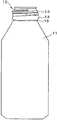
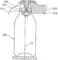
도 1 은, 본 발명의 일 실시예에 관한 병 용기를 나타내는 전체도이다.
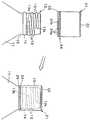
도 2 는, 병 용기와 여기에 피착되는 캡의 관계를 나타내는 설명도이다.
도 3 은, 병 용기에 캡을 피착하는 설명용 단면도이다.
도 4 는, 병 용기에 캡이 피착된 병을 나타내는 요부 확대도이다.
도 5 는, 병 용기의 목부의 확대 부분 단면도이다.
도 6a∼도 6c 는, 종래의 병 용기와 캡을 나타내는 설명도이다.
도 7a∼도 7d 는, 병 용기의 목부에 나사부를 형성하는 설명도이다.
도 8 은, 유효 나사부의 설명도이다.
도 9 는, 본 발명의 일 실시예에 있어서의 금속제 병 용기의 목부의 요부를 나타내는 단면도이다.
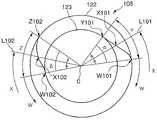
도 10 은, 수 나사부를 상면에서 바라본 나사 감음부의 설명도이다.
도 11 은, 캡이 피착된 종래의 금속제 병 용기의 부분 단면도이다.
도 12 는, 본 발명을 실시하기 위한 나사 성형 장치를 나타내는 설명도이다.
도 13 은, 나사 성형 장치가 병 용기의 목부에 나사부를 형성하고 있는 상태를 나타내는 설명도이다.
도 14 는, 나사 성형 장치의 중자를 나타내는 외관도이다.
도 15 는, 도 14 의 중자에 있어서의 나사 형성부의 확대도이다.
도 16 은, 상기 도 14 의 A 화살표 방향으로 본 도면이다.
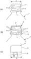
도 17 은, 병 용기의 목부에 나사부를 형성한 상태를 나타내는 설명도이다.
도 18 은, 본 발명의 일 실시예를 나타내는 도면으로, 병 용기의 목부에 형성한 나사부를 나타내는 요부의 확대 설명도이다.
도 19a∼도 19c 는, 병 용기에 나사부를 형성하기 까지의 공정을 나타내는 설명도이다.
도 20 은, 나사부를 갖는 병 용기에 캡을 피착시키는 설명도이다.
도 21 은, 병 용기의 목부에 2.2 권의 나사부를 형성했을 때의 설명도이다.
도 22 는, 병 용기의 나사부에 발생한 종래의 문제점을 나타내는 설명도이다.1 is an overall view showing a bottle container according to an embodiment of the present invention.
2 is an explanatory diagram showing a relationship between a bottle container and a cap adhered thereto.
3 is an explanatory cross-sectional view for attaching a cap to a bottle container.
4 is an enlarged view illustrating a main portion of the bottle in which a cap is attached to the bottle container.
5 is an enlarged partial cross-sectional view of the neck of the bottle container.
6A to 6C are explanatory diagrams showing a conventional bottle container and a cap.
7A to 7D are explanatory diagrams for forming a screw portion in the neck portion of the bottle container.
8 is an explanatory view of an effective screw portion.
9 is a cross-sectional view showing a main portion of a neck of a metal bottle container in one embodiment of the present invention.
It is explanatory drawing of the screw winding part which looked at the male screw part from the upper surface.
11 is a partial cross-sectional view of a conventional metal bottle container having a cap attached thereto.
It is explanatory drawing which shows the screw shaping apparatus for implementing this invention.
It is explanatory drawing which shows the state in which the screw shaping | molding apparatus forms the screw part in the neck part of a bottle container.
It is an external view which shows the core of a screw forming apparatus.
FIG. 15 is an enlarged view of a screw formation part in the middle of FIG. 14.
FIG. 16 is a view seen in the direction of the arrow A in FIG. 14.
It is explanatory drawing which shows the state which provided the screw part in the neck part of a bottle container.
18 is an enlarged explanatory view of a main portion showing a screw portion formed in a neck portion of a bottle container, showing an embodiment of the present invention.
19A to 19C are explanatory diagrams showing a step up to forming a screw portion in a bottle container.
20 is an explanatory diagram for attaching a cap to a bottle container having a screw portion.
It is explanatory drawing at the time of forming the 2.2 screw part in the neck part of a bottle container.
It is explanatory drawing which shows the conventional problem which occurred in the screw part of a bottle container.
이하, 도면을 참조하면서, 본 발명에 관한 금속제 병 용기, 나사 성형 장치, 목부 성형 방법의 바람직한 실시예에 대해서 설명한다. 다만, 본 발명은 이하의 각 실시예에 한정되는 것이 아니라, 예를 들어 이들 실시예의 구성 요소끼리 적절히 조합할 수도 있다.EMBODIMENT OF THE INVENTION Hereinafter, preferred Example of the metal bottle container, the screw shaping | molding apparatus, and the neck shaping | molding method concerning this invention is described, referring drawings. However, this invention is not limited to each following example, For example, the component of these Examples can also be combined suitably.
제 1 실시예First Embodiment
이하, 도면을 참조하여 본 발명의 실시예에 대해 설명한다. 도 1 내지 도 5 는 본 발명의 일 실시예에 관한 병 용기 및, 병 용기에 캡이 피착된 병을 나타내는 도면으로, 도 1 은 병 용기를 나타내는 전체도, 도 2 는 병 용기와 캡의 관계를 나타내는 설명도, 도 3 은 병 용기에 캡이 피착되는 공정의 설명용 단면도, 도 4 는 병 용기에 캡이 피착된 병을 나타내는 요부 확대도, 도 5 는 병 용기의 목부의 확대 부분 단면도이다.Hereinafter, embodiments of the present invention will be described with reference to the drawings. 1 to 5 is a view showing a bottle container and a bottle with a cap attached to the bottle container according to an embodiment of the present invention, Figure 1 is an overall view showing the bottle container, Figure 2 is a relationship between the bottle container and the
이 실시예의 병 용기 (11) 는, 탄산 음료, 과즙 음료 등을 넣기 위한 것으로, 알루미늄 또는 알루미늄 합금으로 이루어져 있고, 도 1 과 같이 병 용기 (11) 의 상부에 목부 (12) 가 형성되어 있다.The
목부 (12) 의 상부 외주에는 나사부 (13) 가 형성되고, 그 나사부 (13) 로부터 하측에는 팽창돌출부 (14) 가 형성되는 동시에, 그 밑으로 네크부 (15) 가 형성되어 있다. 나사부 (13) 는, 병 용기 (11) 에 형성된 목부 (12) 가 직경이 확장되어 직경확장부가 형성된 후, 나사를 형성하는 부분의 직경을 축소시키고, 그 직경이 축소된 부분에 나사 형성기 (도시 생략) 가 나사 절삭 가공을 실시함으로써 형성되고, 팽창돌출부 (14) 는 직경이 축소되지 않고, 나사부 (13) 가 좀더 나사 절삭 가공되었을 때, 나사 절삭되지 않고 남은 직경확장부분에 의해 형성되어 있다.A threaded
그리고, 이 목부 (12) 에, 도 2 와 같이 바닥이 있는 원통형상으로 형성된 캡재 (21) 가 씌워졌을 때, 이 캡재 (21) 가 도 3 에 나타내는 캡핑 장치 (30) 에 의해서 감져 조여짐으로써 목부 (12) 에 도 4 와 같이 캡 (20) 이 피착되고, 이것에 의해 캡 (20) 이 목부 (12) 의 개구단을 밀봉한다.And when the
캡재 (21) 는, 피착되기 전의 단계에서는, 도 2 에 나타내는 바와 같이 그 상부가 천판 (22) 에 의해 막혀지는 동시에 그 하부가 하측을 향하여 일직선으로 개구된 통형상을 이루고 있고, 천판 (22) 의 안쪽에는 라이너 (23) (도 3 및 도 4 참조) 가 장착되어 있다. 캡재 (21) 의 하단에는 브리지부 (24) 를 사이에 두고 캡 본체 하부 (25) 가 형성되어 있다. 브리지부 (24) 는, 복수의 스코어 (24a) 와 브리지 (24b) 가 캡재 (21) 의 둘레 방향으로 번갈아 형성되어 있다.In the step before capping, as shown in FIG. 2, the
이 실시예에서는, 병 용기 (11) 의 목부 (12) 에 형성되는 나사부 (13) 의 유효 나사 권수가 2.2 권으로 형성되어 있다. 즉, 나사부 (13) 는, 목부 (12) 에 직경확장부가 형성되면, 나사 형성기의 나사 절삭 롤러가, 직경이 확장되고 계속해서 직경이 축소된 부분의 주위를 따라서 굴러 이동하여, 이 직경이 확장되고 계속해서 직경이 축소된 부분을 가압하여 나사산과 나사 골을 구획하여 형성함으로써 형성되며, 그 때, 목부 (12) 에 있어서, 도 2 및 도 4 와 같이, 나사부 (13) 로서 유효하게 기능하는 시작 위치 (13a) 와 종료 위치 (13b) 사이의 유효 나사 권수가 2.2 권이 되도록 형성되어 있다. 단, 본 발명에 있어서는, 유효 나사 권수는 2.0∼2.5 권이면 된다.In this embodiment, the effective number of threads of the threaded
이 나사부 (13) 의 유효 나사부는, 도 6a∼도 6c 에 기재된 종래예에서 나타낸 유효 나사부와 동일하게 정의되고, 시작 위치 (13a) (도 8 에서는, 유효 나사 시작점 (X1)) 에서 종료 위치 (13b) (도 8 에서는, 유효 나사 종료점 (X2)) 까지의 나사부로 되어 있다. 또한, 목부 (12) 의 나사부의 외경은, 종래예의 도 6 에서 나타낸 외경 (B) 과 동일하게 정의된다. 이러한 나사부 (13) 를 갖는 병 용기 (11) 는, 목부 (12) 에 형성된 나사부 (13) 의 최대 외경이 28∼38㎜ 이고, 또한 목부 (12) 의 두께가 0.25∼0.4㎜ 의 크기이고, 여기에 1 인치당 8 산의 나사 피치이고 유효 나사 권수가 2.2 권인 나사부 (13) 가 형성된다.The effective screw portion of this
따라서, 이 목부 (12) 에 캡재 (21) 가 도 2 와 같이 씌워지고, 또한 도 3 과 같은 캡핑 장치 (30) 에 의해 캡재 (21) 의 외주에 캡 나사부 (26) 가 형성되어 캡 (20) 이 피착되면, 캡 (20) 에도 유효 나사 권수가 2.2 권으로 이루어지는 나사부가 형성되게 되어 있다.Therefore, the
또한, 도 5 에 나타내는 바와 같이, 목부 (12) 의 선단부에는 선단이 외측으로 구부러져 형성되어 있는 컬부 (27) 와, 컬부 (27) 로부터 하측을 향하여 직경이 확장되도록 형성되어 있는 경사부 (28) 가 형성되어 있다. 나사 시작점 (W1) (도 8 참조) 은, 나사부 (13) 의 대략 최대 외경이 되는 점이고, 나사 시작점 (W1) 을 통과하는 외경을 나사산 외경 (D1) 으로 하고, 컬부 (27) 의 최대 외경부를 통과하는 외경을 컬부 외경 (D2) 으로 한다. 또한, 병 용기 (11) 의 상단면 (29) 으로부터 나사 시작점 (W1) 까지의 높이를 나사 시작점 높이 (h), 상단면 (29) 으로부터 컬부 (27) 의 외측의 최하단점 (T1) 까지의 높이를 컬부 높이 (T) 로 한다.In addition, as shown in FIG. 5, the front end part of the
경사부 (28) 의 경사각 (θ) 은, 나사 시작점 (W1) 으로부터 목부의 상측을 향하는 경사와 중심축 (O) 이 형성하는 각도로, 컬부 (27) 의 외측의 최하단점 (T1) 으로부터 나사 시작점 (W1) 까지의 경사부 (28) 의 평균 각도가 사용된다.The inclination angle θ of the
경사각 (θ) 의 측정은 주식회사 미쯔또요 제조의 컨트레서 CDH-400 을 사용하여, 상기 나사 시작점 (W1) 으로부터 최하단점 (T1) 의 지정 구간선 측정에 의해 실시되었다. 즉, 컨트레서에 의해 중심축 (O) 방향에 있어서 경사부 (28) 의 윤곽 형상을 측정하고, 이 윤곽 형상으로부터 최소 2승법을 사용하여 직선을 구하여, 이 직선과 중심축 (O) 의 각도를 경사각 (θ) 으로 하는 측정을 실시하였다.The measurement of the inclination angle (θ) was carried out by measuring the designated section line of the lowest end point T1 from the screw starting point W1 using a compressor CDH-400 manufactured by Mitsutoyo Corporation. That is, the contour shape of the
또한, 전술한 경사각 (θ) 과 나사 시작점 높이 (h) 의 사이에는 식 1 에 나타내는 관계가 있다.In addition, there is a relationship shown in
[식 1][Formula 1]

식 1 로부터, 나사산 외경 (D1), 컬부 외경 (D2), 및 컬부 높이 (T) 를 고정했을 때, 경사각 (θ) 을 정하면 나사 시작점 높이 (h) 가 정해져, 경사각 (θ) 을 크게 하면 나사 시작점 높이 (h) 가 작아지는 것을 알 수 있다. 이것으로부터, 경사각 (θ) 의 하한치가 나사 시작점 높이 (h) 의 상한치가 되고, 나사 시작점 높이 (h) 의 하한치가 경사각 (θ) 의 상한치가 되는 것을 알 수 있다. h 의 범위는, 0.7≤(D1-D2)/h≤1.3 이면 되고, 보다 바람직하게는, 3.24㎜≤h≤5.6㎜ 이면 된다.From
캡핑 장치 (30) 는, 주로 도 3 에 나타내는 바와 같이, 병 용기 (11) 에 씌운 캡재 (21) 의 천판 (22) 을 하측으로 가압하는 압력 블록 (35) 과, 캡재 (21) 를 외주로부터 목부 (12) 에 밀어 누르는 동시에, 목부 (12) 의 나사부 (13) 를 따라 캡재 (21) 의 외주를 감아 조임으로써 캡 나사부 (26) 를 형성하는 RO 롤러 (32) 와, 캡재 (21) 의 캡 본체 하부 (25) 를 외주로부터 팽창돌출부 (14) 의 하부에 감아 필퍼 프루프부를 형성하는 PP 롤러 (33) 를 구비하고 있다.As shown in FIG. 3, the
또, 가압체 (35) 는, 캡재 (21) 의 천판 (22) 을 가압하는 가압체 (31) 를 구비하고, 탄성 지지 스프링 (34) 을 통하여 압력 샤프트 (37) 에 연결되며, 캡부 (20) 를 피착시킬 때, 목부 (12) 에 씌운 캡재 (21) 의 천판 (22) 을 가압하는 누름 하중이 목부 (12) 의 구경의 크기에 따라 바뀌어지도록 되어 있다. RO 롤러 (32) 및 PP 롤러 (33) 는, 지지 아암 (36) 에 의해 병 용기 (11) 및 캡재 (21) 의 둘레를 회전 가능하도록 구성되어 있다.Moreover, the
이 실시예의 병 용기 (11) 는, 상기한 바와 같이 목부 (12) 에 형성된 나사부 (13) 의 유효 나사 권수가 2.2 권으로 형성되어 있고, 여기에 캡 (20) 을 피착시키기 위해, 도 2 와 같이 바닥이 있는 원통형상의 캡재 (21) 를 씌운 후, 캡핑 장치 (30) 를 구동하여 캡핑 장치 (30) 의 압력 블록 (35) 이 도 3 과 같이 캡재 (21) 를 병 용기 (11) 의 바닥부 방향으로 누르면서, 또한 RO 롤러 (32) 가 병 용기 (11) 의 나사부 (13) 를 따르도록 목부 (12) 의 주위를 따라 회전하면, 도 4 에 나타내는 바와 같이, 캡재 (21) 의 외주에 목부 (12) 의 나사부 (13) 에 대응하는 캡 나사부 (26) 가 형성되고, 또한 PP 롤러 (33) 에 의해 캡재 (21) 의 캡 본체 하부 (25) 가 팽창돌출부 (14) 에 감겨 조여져, 이로써 병 용기 (11) 에 캡 (20) 이 피착되게 된다.In the
전술한 바와 같은 병 용기 (11) 및 캡 (20) 을 사용하여, 내하중 시험 및 누출 시험을 실시하였다. 실험은, 나사산 외경 (D1) 이 38㎜, 33㎜, 28㎜ 인 3 종류의 병 용기 (11) 및 캡 (20) 에 있어서, 경사각 (θ) 및 나사 시작점 높이 (h) 를 변경하여 실시되었다. 실험에는, 판 두께가 0.24∼0.4㎜ 이고, 나사부 (13) 에 1 인치당 8 산 피치의 나사를 유효 나사 권수 2.2 권으로 형성한 병 용기 (11) 가 사용되고, 180∼230N/㎜2 의 인장강도를 가지고, 판 두께 0.25㎜ 이며, 폴리에틸렌 또는 폴리프로필렌의 라이너 (23) 가 부착된 캡 (20) 이 사용되었다.Using the
내하중 시험은 병 용기 (11) 의 축 방향으로 하중을 증가시켜 나가, 1600N 미만에서 좌굴된 병 용기 (11) 를 불합격 (×), 1600N 이상에서 좌굴된 병 용기 (11) 를 합격 (○) 으로 평가하였다. 누출 시험은, 상온 상태에서 내압이 0.1MPa 로 충전된 병 (10) 의 중량을 측정하고, 병 (10) 을 37℃ 의 상태에서 1 일 경과시킨 후, 상온 상태에서 다시 중량을 측정하여, 그 중량차가 0.2㎎ 미만인 병 (10) 을 합격 (○), 중량차가 0.2㎎ 이상인 병 (10) 을 불합격 (×) 으로 평가하였다. 실험 결과를 표 1 에 나타낸다.The load-bearing test increases the load in the axial direction of the

표 1 에 있어서, 나사 시작점 높이 (h) 가 짧아지면, 즉 경사각 (θ) 이 커지면 좌굴이 발생하고, 또한, 나사 시작점 높이 (h) 가 길어지면, 즉 경사각 (θ) 이 작아지면 누출이 발생하고 있음을 알 수 있다. 이것으로부터, 종합 평가로서 좌굴도 누출도 발생하지 않는 나사 시작점 높이 (h) 및 경사각 (θ) 의 범위를 ○로 평가하고, 그 외의 것을 ×로 평가하였다. 종합 평가가 ○로 평가되는 범위는, 나사산 외경 (D1) 이 38㎜ 인 병 (10) 에 있어서, 3.6㎜≤h≤5.6㎜, 33.0°≤θ≤55.0°, 나사산 외경 (D1) 이 33㎜ 인 병 (10) 에 있어서, 3.24㎜≤h≤4.74㎜, 32.5°≤θ≤54.6°, 나사산 외경 (D1) 이 28㎜ 인 병 (10) 에 있어서, 3.4㎜≤h≤5.1mm, 33.0°≤θ≤55.0°이다.In Table 1, buckling occurs when the screw starting point height h becomes short, that is, when the inclination angle θ becomes large, and leakage occurs when the screw starting point height h becomes long, that is, when the inclination angle θ becomes small. It can be seen that. From this, as a comprehensive evaluation, the range of the screw starting point height h and inclination-angle (theta) which neither buckling nor leakage generate | occur | produced was evaluated by (circle), and the others were evaluated by x. The range in which the overall evaluation is evaluated as ○ is 3.6 mm ≦ h ≦ 5.6 mm, 33.0 ° ≦ θ ≦ 55.0 °, and thread outer diameter D1 of 33 mm in the
전술한 바와 같이 본 실시예의 병 용기 (11) 는, 목부 (12) 에 형성된 나사부 (13) 의 유효 나사 권수가 2.2 권으로 형성되어 있기 때문에, 캡 (20) 의 피착 공정에 있어서 압력 블록 (35) 의 압력에 의해 나사부 (13) 의 휨이 기울어지는 일이 없다. 이것에 의해, 캡 (20) 에 대한 각 RO 롤러 (32) 의 가압 높이 위치에 편차가 생기지 않게 되어, 나사 감기 불량을 일으키는 일이 없다. 또, 나사 개수가 3 개인 부분이 적기 때문에, 캡 (20) 의 피착시에 브리지 끊김이 발생하기 어렵다.As described above, since the effective number of threads of the threaded
한편, 병 용기 (11) 에 캡 (20) 이 피착되면, 병 (10) 안을 양압으로 한 경우, 캡 (20) 에 병 용기 (11) 의 목부 (12) 의 내측으로부터 밀어 올리는 힘이 작용하지만, 전술한 바와 같이, 목부 (12) 의 나사부 (13) 와 캡 나사부 (26) 의 유효 나사 권수가 2.2 권이고, 나사부 (13) 와 캡 나사부 (26) 가 동일한 힘으로 체결되어 있어, 캡 (20) 이 병 용기 (11) 에 대하여 기울어지는 일이 없고, 캡 (20) 의 브리지부 (24) 가 끊어질 우려가 없다. 또한, 뚜껑 열기시의 토크가 필요 이상으로 상승하는 일도 없다.On the other hand, when the
그 결과, 이 실시예에 의하면, 병 용기 (11) 에 캡 (20) 을 양호하게 피착시킬 수 있고, 피착 후에도 캡 (20) 의 양호한 상태를 확실하게 유지할 수 있으며, 따라서, 병 용기 (11) 의 나사부 (13) 의 권수에 의해 발생하는 종래의 문제점을 해소할 수 있기 때문에, 병 (10) 으로서의 신뢰성을 높일 수 있다.As a result, according to this embodiment, the
또한, 병 용기 (11) 는, 나사 시작점 높이 (h) 가 3.24㎜≤h≤5.6㎜ 의 범위에서 형성되어 있기 때문에, 규정된 내압 이하에 있어서 컬부 (27) 와 라이너 (23) 사이에서 양호한 밀착성을 얻을 수 있다. 즉, 내압에 의해 캡 (20) 의 캡 나사부 (26) 와 천판 (22) 사이가 신장되지만, 이 신장량은 나사 시작점 높이 (h) 에 의해 정해지고, 나사 시작점 높이 (h) 를 상기 범위로 함으로써 누출이 발생하지 않는 신장량으로 할 수 있는 것이다. 이것에 의해, 규정 내압에 있어서 양호한 밀봉성을 갖는 병 용기 (11) 를 형성할 수 있다.Moreover, since the bottle starting point height h is formed in the range of 3.24 mm <= h <= 5.6mm, the
또한, 경사각 (θ) 이 33°≤θ≤55°의 범위로 형성되어 있기 때문에, 캡 (20) 의 피착 공정에 있어서, 캡 (20) 을 누르는 하중에 견딜 수 있는 내하중성을 얻을 수 있다. 또한, 유효 나사 권수가 2.0 내지 2.5 권이 되도록 목부 (12) 가 형성되어 있기 때문에, 병 (10) 의 내압에 의해 어긋남이 생기는 일 없이, 캡 (20) 이 확실히 피착되는 병 용기 (11) 를 형성할 수 있는 동시에 뚜껑 열기시의 토크의 상승을 억제할 수 있다.Moreover, since the inclination angle (theta) is formed in the range of 33 degrees <= (theta) <= 55 degrees, the load resistance which can endure the load which presses the
또, 도시된 실시예에서는, 병 용기 (11) 의 목부 (12) 에 형성되는 나사부 (13) 및 캡 (20) 에 형성되는 캡 나사부 (26) 의 유효 나사 권수가 2.2 권으로 형성된 예를 나타냈지만, 적어도 2.0 권 이상, 또한 2.5 권 이하의 유효 나사 권수이면 된다. 그리고, 2.0∼2.3 권으로 형성되어 있으면, 불완전 나사부가 축방향으로 중복되지 않아, 나사 성형이 안정적으로 이루어지고, 나사가 3 개인 부분이 없어지기 때문에 보다 바람직하다.In the illustrated embodiment, an example in which the effective screw turns of the threaded
따라서, 본 발명에 있어서는, 병 용기 (11) 의 목부 (12) 에 형성된 나사부 (13) 의 최대 외경이 28∼38㎜ 이고, 그 두께가 0.25∼0.4㎜ 이며, 또한 유효 나사의 권수가 2.0∼2.5 권이고, 바람직하게는 2.2∼2.3 권으로 형성되어 있으면, 상술한 작용 효과를 발휘할 수 있다.Therefore, in this invention, the maximum outer diameter of the
제 2 실시예Second Embodiment
이하, 도면을 참조하여 본 발명의 실시예에 대해 설명한다.Hereinafter, embodiments of the present invention will be described with reference to the drawings.
도 9 에 금속제 병 용기의 목부의 부분 단면도를 나타낸다. 금속제 병 용기 (이하, 병 용기라고 한다: 102) 의 목부는, 선단이 외측으로 구부러져 컬부 (107) 가 형성되어 있고, 컬부 (107) 를 구성하는 곡면에서 최상단이 되는 면이 상단면 (120) 으로 되어 있다. 컬부 (107) 로부터 하측을 향하여 직경이 확장되는 경사부 (121) 가 형성되고, 경사부 (121) 의 하측으로 나사산 (122) 과 나사 골 (123) 를 갖는 수 나사부 (105) 가 형성되어 있다.9 is a partial cross-sectional view of the neck of the metal bottle container. The neck of the metal bottle container (hereinafter referred to as a bottle container: 102) is bent at the front end thereof to form a
또한, 수 나사부 (105) 의 상단부에 있어서 경사부 (121) 의 일부가 둘레 방향을 향하여 서서히 돌출되어 규정된 나사산 (122) 의 높이가 될 때까지 돌출 높이가 높아져 나사 시단부(始端部)가 형성되고, 수 나사부 (105) 의 하단부에 있어서 나사 골 (123) 의 깊이가 둘레 방향을 향하여 서서히 얕아져 나사 종단부가 형성되어 있다.Further, the protruding height is increased until a part of the
도 9 에 나타내는 단면도에 있어서, 나사 시작점 (W101) 은 나사산 (122) 의 대략 최대 외경이 되는 점이고, 나사 시작점 (W101) 을 통과하는 외경을 나사산 외경 (D101) 으로 하며, 컬부 (107) 의 최외부를 통과하는 외경을 컬부 외경 (D102) 으로 한다. 또한, 병 용기 (102) 의 상단면 (120) 으로부터 나사 시작점 (W101) 까지의 높이를 나사 시작점 높이 (h), 상단면 (120) 으로부터 컬부 (107) 의 외측의 최하단점 (T101) 까지의 높이를 컬부 높이 (T) 로 한다.In the sectional drawing shown in FIG. 9, the thread starting point W101 is a point which becomes the substantially maximum outer diameter of the
경사부 (121) 의 경사각 (θ) 은, 나사 시작점 (W101) 으로부터 목부의 상측을 향하는 경사와 중심축 (O) 이 형성하는 각도로, 컬부 (107) 의 외측의 최하단점 (T101) 으로부터 나사 시작점 (W101) 까지의 경사부의 평균 각도가 사용된다.The inclination angle θ of the
경사각 (θ) 의 측정은 주식회사 미쯔또요 제조의 컨트레서 CDH-400 을 사용하여, 상기 W101 에서 T101 의 지정 구간선 측정을 실시하였다.The measurement of inclination angle (theta) measured the designated section line of T101 from said W101 using the compressor CDH-400 by Mitsutoyo Corporation.
또한, 전술한 경사각 (θ) 과 나사 시작점 높이 (h) 의 사이에도 전술한 식 1 에 나타내는 관계가 있다.Moreover, there exists a relationship shown in
단, 이 실시예의 나사산 외경 (D101) 은, 제 1 실시예의 나사산 외경 (D1) 에 상당한다. 컬부 외경 (D102) 은 제 1 실시예의 컬부 외경 (D2) 에 상당한다. 나사 시작점 (W101) 은, 제 1 실시예의 나사 시작점 (W1) 에 상당한다. 최하단점 (T101) 은, 제 1 실시예의 최하단점 (T1) 에 상당한다.However, the thread outer diameter D101 of this embodiment corresponds to the thread outer diameter D1 of the first embodiment. The curl outer diameter D102 corresponds to the curl outer diameter D2 of the first embodiment. The screw starting point W101 corresponds to the screw starting point W1 of the first embodiment. The lowest end point T101 corresponds to the lowest end point T1 of the first embodiment.
또한, 도 10 에 나타낸 수 나사부 (105) 를 상면에서 바라본 설명도를 사용하여, 나사 시단부 (Y), 나사 종단부 (Z), 및 유효 나사부 (X) 에 대해서 설명한다. 나사 시단부 (Y) 및 나사 종단부 (Z) 는, 나사산 (122) 의 높이 및 나사 골 (123) 의 깊이가 둘레 방향으로 일정하지 않고, 불완전한 나사부이다. 이에 대하여 완전 나사부 (W) 는, 규정된 나사 높이 및 나사 깊이로 형성되어 있다. 나사 시단부 (Y) 에 있어서 불완전한 나사산은, 나사 시단부 (Y) 의 단점 (端点) (Y101) 으로부터 서서히 높아지도록 돌출되어 형성되어, 완전 나사부 (W) 의 나사 시작점 (W101) 에서 나사산 (122) 의 규정된 높이로 형성된다. 또한, 나사 종단부 (Z) 에 있어서 불완전한 나사 골은, 완전 나사부 (W) 의 나사 종료점 (W102) 으로부터 서서히 깊이가 얕아지도록 형성되어, 나사 종단부 (Z) 의 단점 (Z102) 에서 깊이가 없어지고 평탄한 면으로 된다.Moreover, the screw start-end part Y, the screw end part Z, and the effective screw part X are demonstrated using the explanatory drawing which looked at the
유효 나사부 (X) 는, 나사 시단부 (Y) 의 중간의 유효 나사 시작점 (X101) 으로부터 완전 나사부 (W) 전체를 포함하고, 나사 종단부 (Z) 의 중간의 유효 나사 종료점 (X102) 까지의 나사부로 된다. 유효 나사 시작점 (X101) 은, 단점 (Y101) 과 중심점 (C) 과 나사 시작점 (W101) 에 의해 만들어지는 나사 시단부 (Y) 의 협각 (∠α) 의 2 등분선 (L101) 과, 나사 시단부 (Y) 와의 교점이다. 또한, 유효 나사 종료점 (X102) 은, 나사 종료점 (W102) 과 중심점 (C) 과 단점 (Z102) 에 의해 만들어지는 나사 종단부 (Z) 의 협각 (∠β) 의 2 등분선 (L102) 과, 나사 종단부 (Z) 와의 교점이다.The effective screw portion X includes the entire threaded portion W from the effective screw starting point X101 in the middle of the screw start end Y to the effective screw ending point X102 in the middle of the screw end Z. It becomes a screw part. The effective screw starting point X101 is the bisector L101 of the narrow angle α of the screw starting end Y made by the disadvantage Y101 and the center point C and the screw starting point W101, and the screw starting end. It is the intersection with negative (Y). In addition, the effective screw end point X102 is a bisector L102 of the narrow angle ∠β of the screw end Z formed by the screw end point W102, the center point C, and the disadvantage Z102, Intersect with screw end (Z).
전술한 바와 같은 병 용기 (102) 및 캡 (103) 을 사용하여, 내하중 시험 및 누출 시험을 실시하였다. 실험은, 나사산 외경 (D101) 이 38㎜, 33㎜, 28㎜ 인 3 종류의 병 용기 (102) 및 캡 (103) 에 있어서, 경사각 (θ) 및 나사 시작점 높이 (h) 를 변경하여 실시되었다. 실험에는, 판 두께가 0.24∼0.4㎜ 이고, 수 나사부 (105) 에 1 인치당 8 산 피치의 나사를 유효 나사 권수 2.2 권으로 형성한 병 용기 (102) 가 사용되고, 180∼230N/㎜2 의 인장강도를 갖는 캡 (103) 이 사용되었다.Using the
내하중 시험은 병 용기 (102) 의 축 방향으로 하중을 증가시켜 나가, 1600N 미만에서 좌굴된 병 용기 (102) 를 불합격 (×), 1600N 이상에서 좌굴된 병 용기 (102) 를 합격 (○) 으로 평가하였다. 누출 시험은, 상온 상태에서 내압이 0.1MPa 로 충전된 캡이 부착된 병 용기 (101) 의 중량을 측정하고, 캡이 부착된 병 용기 (101) 를 37℃ 의 상태에서 1 일 경과시킨 후, 상온 상태에서 다시 중량을 측정하여, 그 중량차가 0.2㎎ 미만인 캡이 부착된 병 용기 (101) 를 합격 (○), 중량차가 0.2㎎ 이상인 캡이 부착된 병 용기 (101) 를 불합격 (×) 으로 평가하였다. 그 실험 결과의 상세한 내용은 전술한 표 1 에 나타낸다.The load-bearing test increases the load in the axial direction of the
표 1 에 있어서, 나사 시작점 높이 (h) 가 짧아지면, 즉 경사각 (θ) 이 커지면 좌굴이 발생하고, 또한, 나사 시작점 높이 (h) 가 길어지면, 즉 경사각 (θ) 이 작아지면 누출이 발생하고 있음을 알 수 있다. 이것으로부터, 종합 평가로서 좌굴도 누출도 발생하지 않는 나사 시작점 높이 (h) 및 경사각 (θ) 의 범위를 ○로 평가하고, 그 외의 것을 ×로 평가하였다. 종합 평가가 ○로 평가되는 범위는, 나사산 외경 (D101) 이 38㎜ 인 캡이 부착된 병 용기 (101) 에 있어서, 3.6㎜≤h≤5.6㎜, 33.0°≤θ≤55.0°, 나사산 외경 (D101) 이 33㎜ 인 캡이 부착된 병 용기 (101) 에 있어서, 3.24㎜≤h≤4.74㎜, 32.5°≤θ≤54.6°, 나사산 외경 (D101) 이 28㎜ 인 캡이 부착된 병 용기 (101) 에 있어서, 3.4㎜≤h≤5.1mm, 33.0°≤θ≤55.0°이다.In Table 1, buckling occurs when the screw starting point height h becomes short, that is, when the inclination angle θ becomes large, and leakage occurs when the screw starting point height h becomes long, that is, when the inclination angle θ becomes small. It can be seen that. From this, as a comprehensive evaluation, the range of the screw starting point height h and inclination-angle (theta) which neither buckling nor leakage generate | occur | produced was evaluated by (circle), and the others were evaluated by x. The range in which the comprehensive evaluation is evaluated as ○ is 3.6 mm ≦ h ≦ 5.6 mm, 33.0 ° ≦ θ ≦ 55.0 ° in the
전술한 바와 같이 본 실시예의 캡이 부착된 병 용기 (101) 는, 나사 시작점 높이 (h) 가 3.24㎜≤h≤5.6㎜ 의 범위로 형성되어 있기 때문에, 규정된 내압 이하에 있어서 컬부 (107) 와 라이너 (112) 의 사이에서 양호한 밀착성을 얻을 수 있다. 즉, 내압에 의해 캡 (103) 의 암 나사부 (104) 와 천장면부 (108) 사이가 신장되지만, 이 신장량은 나사 시작점 높이 (h) 에 의해 정해지고, 나사 시작점 높이 (h) 를 상기 범위로 함으로써 누출이 발생하지 않는 신장량으로 할 수 있는 것이다. 이것에 의해, 규정 내압에 있어서 양호한 밀봉성을 갖는 병 용기 (102) 를 형성할 수 있다. 또, 캡 (103) 의 암 나사부 (104) 와 천장면부 (108) 의 사이에 널부 (113) 가 형성되어 있는 경우에 있어서도, 나사 시작점 높이 (h) 를 상기 범위로 함으로써 양호한 밀착성을 얻을 수 있다.As mentioned above, since the bottle starting point height h of the
또한, 경사각 (θ) 이 33°≤θ≤55°의 범위에서 형성되어 있기 때문에, 캡 (20) 의 피착 공정에 있어서, 캡 (103) 을 누르는 하중에 견딜 수 있는 내하중성을 얻을 수 있다. 또한, 유효 나사 권수가 2.0 내지 2.5 권이 되도록 목부 (104) 가 형성되어 있기 때문에, 캡이 부착된 병 용기 (101) 의 내압에 의해 어긋남이 생기는 일 없이, 캡 (103) 이 확실히 피착되는 병 용기 (102) 를 형성할 수 있는 동시에 뚜껑 열기시의 토크의 상승을 억제할 수 있다.In addition, since the inclination angle θ is formed in a range of 33 ° ≦ θ ≦ 55 °, in the deposition process of the
또, 본 실시예에서는, 나사산 외경 (D101) 이 38㎜, 33㎜, 28㎜ 인 3 종류의 캡이 부착된 병 용기 (201) 를 사용하여 설명했지만, 상기 이외의 나사산 외경 (D101) 의 캡이 부착된 병 용기 (101) 에 본 발명을 사용해도 된다.In addition, in the present Example, although demonstrated using the
제 3 실시예Third Embodiment
이하, 도면을 참조하여, 본 발명의 제 3 실시예에 대해 설명한다. 도 12 내지 도 17 은 본 발명의 제 3 실시예에 따른 목부 성형 방법을 나타내는 도면으로, 도 12 는 목부 성형 방법을 실시하기 위한 나사 성형 장치를 나타내는 설명도, 도 13 은 나사 성형 장치가 병 용기의 목부에 나사부를 형성하고 있는 상태를 나타내는 설명도, 도 14 는 나사 성형 장치의 중자를 나타내는 외관도, 도 15 는 도 14 의 중자에 있어서의 나사 형성부의 확대도, 도 16 은 도 14 의 A 화살표 방향으로 본 도면, 도 17 은 병 용기의 목부에 나사부를 형성한 상태를 나타내는 설명도이다.EMBODIMENT OF THE INVENTION Hereinafter, with reference to drawings, the 3rd Embodiment of this invention is described. 12 to 17 are diagrams illustrating a neck molding method according to a third embodiment of the present invention, FIG. 12 is an explanatory view showing a screw molding apparatus for implementing the neck molding method, and FIG. 13 is a bottle container with a screw molding apparatus. Explanatory drawing which shows the state which has formed the screw part in the neck part, FIG. 14 is an external view which shows the middle of a screw forming apparatus, FIG. 15 is an enlarged view of the screw formation part in the middle of FIG. 14, FIG. 16 is A of FIG. 17 is an explanatory view showing a state in which a screw portion is formed in the neck portion of the bottle container.
이 실시예의 목부 성형 방법을 설명하기 전에, 이 목부 성형 방법에서 취급하는 병 용기 (201) 는, 내부에 탄산 음료, 과즙 음료 등의 내용물을 넣기 위한 것으로, 알루미늄 또는 알루미늄 합금으로 이루어지는 박판 금속에 의해 바닥이 있는 통형상으로 형성된 후, 그 병 용기 (201) 의 개구부에 용기의 보디보다 소직경인 목부 (202) 가 형성되고, 그 후, 목부 (202) 의 주위에 나사 형성 장치 (210) 에 의해 나사부 (203) 가 형성된다 (도 19a∼도 19c 참조).Before explaining the neck shaping method of this embodiment, the
본 발명에 있어서는, 병 용기 (201) 의 목부 (202) 의 유효 나사 권수는 2.0 내지 2.5 권으로 되어 있다.In the present invention, the effective number of threads of the
그리고, 목부 성형 방법을 실시하기 위한 나사 성형 장치는, 크게 나눠, 병 용기 (201) 의 목부 (202) 의 내주면에 맞닿는 중자 (211) 와, 외주면에 맞닿는 외자 (212: 외측체) 를 갖고, 중자 (211) 와 외자 (212) 사이에 목부 (202) 를 끼워 넣고서 병 용기 (201) 의 축심 (O) 둘레를 회전함으로써, 목부 (202) 의 주위에 나사부 (203) 가 형성되게 되어 있다.And the screw shaping | molding apparatus for implementing a neck shaping | molding method is divided largely, and has the core 211 which contact | connects the inner peripheral surface of the
이들 중자 (211) 및 외자 (212) 는, 도 12 및 도 13 에 나타내는 바와 같이, 그 외주면에 나사부 (203) 를 형성하기 위한 요철형상의 나사 형성부 (221, 222) 가 나선 모양으로, 또한 서로 대응하는 형상으로 각각 형성되어 있고, 도시를 생략한 구동 기구에 의해 회전된다.12 and 13, these
워크 지지부 (230) 는, 상세히 도시되어 있지 않지만, 척 기능을 가지고, 워크인 병 용기 (201) 를 보유지지한다.Although not shown in detail, the
이 나사 형성 장치 (210) 는, 미리, 워크 지지부 (230) 의 다이 링에 바닥부가 지지된 병 용기 (201) 가, 도 12 에 나타내는 바와 같이, 대향하는 위치로 위치 결정되면, 우선 워크 지지부 (230) 의 전진에 의해 도시를 생략한 원통면이 병 용기 (201) 의 쇼울더부에서 용기 보디부에 끼워지고, 또 중자 (211) 가 병 용기 (201) 의 목부 (202) 의 내주면으로 이동하여 맞닿는 동시에, 외자 (212) 가 목부 (202) 의 외주면으로 이동하여 맞닿음으로써, 중자 (211) 와 외자 (212) 사이에 목부 (202) 를 끼우고, 이 상태에서 다시 장치 (210) 전체가 축심 (O) 둘레를 회전한다. 이것에 의해, 목부 (202) 에 나사부 (203) 가 형성되게 되어 있다.When the
그 경우, 병 용기 (201) 의 목부 (202) 에 형성되는 나사부 (203) 는, 본 예에서는 권수가 2.2 권으로 형성된다. 2.2 권의 나사부 (203) 는, 도 14 와 같이, 목부 (202) 의 외주면에 있어서 제 1 단의 나사산 (203a) 과 제 2 단의 나사산 (203b) 과 제 3 단의 나사산 (203c) 의 3 단으로 이루어지는 나사산 영역 (L) 이 존재하게 된다. 이 때문에, 중자 (211) 에 형성된 요철형상의 나사 형성부 (221) 는, 도 14 에 나타내는 바와 같이, 나사부 (203) 에 대응하는 형상으로 형성되어 있다.In that case, the
이 실시예에서는, 목부 (202) 의 외주에 대한 나사부 (203) 의 형성시, 제 1 단의 나사산 (203a) 이, 도 17 에 나타내는 바와 같이, 제 2 단의 나사산 (203b) 및 제 3 단의 나사산 (203c) 의 높이보다 미리 약간 낮은 치수 (△) 로 형성되어 있다.In this embodiment, when the threaded
즉, 도 15 에 나타내는 바와 같이, 중자 (211) 의 나사 형성부 (221) 에 있어서는, 제 1 단의 나사 형성부 (221a) 의 높이가, 제 2 단의 나사 형성부 (221b) 및 제 3 단의 나사 형성부 (221c) 보다 약간 낮은 치수 (△) 로 형성되고, 이것에 의해서, 중자 (211) 와 외자 (212) 에 의하여 병 용기 (201) 의 목부 (202) 에 나사부 (203) 를 형성했을 때, 도 17 에 실선으로 나타내는 바와 같이, 목부 (202) 의 나사 시작부 (203A) 측인 제 1 단의 나사산 (203a) 이, 제 2 단의 나사산 (203b) 및 제 3 단의 나사산 (203c) 보다 치수 (△) 만큼 미리 낮게 형성되도록 되어 있다.That is, as shown in FIG. 15, in the
이 경우, △ 로는, 예를 들어 0.8㎜ 의 나사산 높이를 설정치로 하면, 그보다 0.1mm 정도 낮은 값으로 되어 있고, 따라서 0.7㎜ 정도로 되어 있지만, 엄밀하게는 적절히 선정하는 것이 바람직하다.In this case, as Δ, for example, when a screw height of 0.8 mm is set as the set value, the value is approximately 0.1 mm lower than that, and accordingly, it is about 0.7 mm, but it is preferable to select it properly.
또한, 중자 (211) 의 나사 형성부 (221) 에 있어서, 제 1 단의 나사 형성부 (221a) 가, 제 2 단의 나사 형성부 (221b) 및 제 3 단의 나사 형성부 (221c) 보다 낮게 되어 있는 범위로는, 본 예에서는, 도 16 에 나타내는 바와 같이, 나사산 영역 (L) 을 포함하는 90 도의 각도 범위 (α) 이다. 이 경우, 제 1 단의 나사 형성부 (221a) 의 나사 시작부 (221A) 를 0 도로 하고, 거기서부터 나사 방향으로 90 도의 각도 범위 (α) 이다.In addition, in the
단, 90 도의 범위에 한정되지 않고, 나사부 (203) 의 권수의 변화나 나사산이 눌러 찌부러질 가능성의 영역 등을 고려하면, 360 도까지의 각도 범위로 하는 것이 대체로 양호하며, 보다 바람직하게는 200∼300 도 (α1) 의 각도 범위이다.However, the present invention is not limited to the range of 90 degrees, and considering the change in the number of turns of the threaded
또, 나사 형성부 (221) 의 나사 시작부 (221A) 란, 목부 (202) 에 형성된 나사부 (203) 가 나사로서 유효하게 기능하는 부분으로, 나사부 (203) 의 나사 시작부 (203A) 에 상당한다. 따라서, 나사 종료부 (221B) 및 나사부 (203) 의 나사 종료부 (203B) 도 이것에 준하고 있다.In addition, the screw start
또, 도 1∼도 6 에 있어서, 도 19a∼도 22 와 동일 부분에는 동일 부호를 붙이고 있다.1-6, the same code | symbol is attached | subjected to the same part as FIG. 19A-22.
이 나사 성형 장치 (210) 는, 상기한 바와 같이 구성되어 있기 때문에, 다음에, 그 동작에 관련하여 본 발명 방법의 일 실시예에 대해서 설명한다.Since this screw shaping | molding apparatus 210 is comprised as mentioned above, one Example of the method of this invention is demonstrated next regarding the operation | movement.
우선, 병 용기 (201) 에 나사부 (203) 를 형성하기 위해, 도시를 생략한 다이 링 및 링형상의 도시를 생략한 중공 탄성부재로 이루어지는 워크 지지부 (230) 에 바닥부가 지지된 병 용기 (201) 가 대향하는 위치로 위치 결정되고, 워크 지지부 (230) 의 전진에 의해 도시를 생략한 원통면이 병 용기 (201) 의 쇼울더부로부터 용기 보디부에 끼워지고, 또 중자 (211) 가 병 용기의 목부 (202) 내주부로 이동하여 맞닿는 동시에, 외자 (212) 가 목부 (202) 외주부로 이동하여 맞닿음으로써, 중자 (211) 와 외자 (212) 사이에 목부 (202) 를 끼워 넣고, 이 상태로 다시 장치 전체가 축심 (O) 둘레를 회전함으로써, 목부 (202) 에 도 17 에 실선으로 나타내는 바와 같은 나사부 (203) 가 형성되게 된다.First, in order to form the
그 경우, 중자 (211) 와 외자 (212) 의 회전에 의해 2.2 권의 나사부 (203) 를 목부 (202) 의 외주면을 따라 형성하면, 중자 (211) 의 제 1 단의 나사 형성부 (221a) 의 높이가 제 2 단의 나사 형성부 (221b), 제 3 단의 나사 형성부 (221c) 보다 낮게 되어 있기 때문에, 목부 (202) 에 형성된 나사산 영역 중, 제 1 단의 나사산 (203a) 이 제 2 단의 나사산 (203b), 제 3 단의 나사산 (203c) 의 각각의 높이보다 낮게 형성된다.In that case, when the
이렇게 해서 목부 (202) 의 외주에 나사부 (203) 가 형성된 후, 이 나사부 (203) 를 갖는 목부 (202) 의 선단에 컬부 (208) 를 형성하기 위해, 도시를 생략한 캡 피착 장치에 의해서 캡 피착 공정을 실시하면, 캡 피착 장치가 병 용기 (201) 를 용기 바닥 방향으로 가압하면서 목부 (202) 의 선단을 외측에서 안쪽으로 되꺾어 컬부 (208) (도 20 및 도 22) 를 형성하기 때문에, 목부 (202) 의 선단이 가압력을 받아 목부 (202) 에 있어서의 제 1 단의 나사산 (203a) 이 눌러 찌부러짐으로써, 제 1 단의 나사산 (203a) 이 도 17 의 실선에서 쇄선과 같이 직경이 확장된다.In this way, after the
이 경우, 전술한 바와 같이, 목부 (202) 에 있어서의 제 1 단의 나사산 (203a) 이, 제 2 단의 나사산 (203b) 및 제 3 단의 나사산 (203c) 의 높이보다 미리 낮은 치수 (△) 로 형성되어 있기 때문에, 캡 피착 공정의 가압력에 의해 눌러 찌부러짐으로써 직경이 확장되어도, 결과적으로는 제 2 단의 나사산 (203b) 및 제 3 단의 나사산 (203c) 과 대략 동일한 높이가 된다.In this case, as described above, the
따라서, 본 발명에 의하면, 목부 (202) 의 나사부 (203) 에서의 제 1 단의 나사산 (203a) 을 사전에 낮게 형성해 두고, 그 후, 목부 (202) 의 선단에 캡 피착 공정에 의해서 가압력을 작용시키면, 그 때의 가압력에 의해 제 1 단의 나사산 (203a) 의 높이를 제 2 단의 나사산 (203b), 제 3 단의 나사산 (203c) 의 높이와 대략 동일하게 할 수 있기 때문에, 나사산을 대략 균일화시킬 수 있다.Therefore, according to this invention, the
이 때문에, 이러한 병 용기 (201) 에 캡 (205) 이 피착되면, 캡 (205) 이 천판측과 개구단측에서 대략 동일 직경이 되는 일직선의 바닥이 있는 원통형상으로 되기 때문에, 이용자가 병 용기 (201) 를 뚜껑을 연 후에 다시 뚜껑을 닫을 때, 원활하게 뚜껑을 닫을 수 있어 위화감을 주는 일이 없어지고, 종래와 같이 발형상(鉢狀)의 캡으로 되는 문제를 해소할 수 있어, 그만큼 신뢰성을 높일 수 있다.For this reason, when the
그리고, 이 나사 성형 장치 (210) 에 의하면, 중자 (211) 에 있어서의 제 1 단의 나사 형성부 (221a) 만의 높이를 다른 나사 형성부 (221b, 221c) 보다 낮게 함으로써, 목부 (202) 의 나사부 (203) 에서의 제 1 단의 나사산 (203a) 을 미리 낮게 형성할 수 있어, 캡의 닫기가 양호해지는 나사부 (203) 를 정확하게 형성할 수 있다.And according to this screw shaping | molding apparatus 210, by making the height of only the
도 18 은, 본 발명의 제 2 실시예를 나타내는 도면으로, 병 용기의 목부에 형성한 나사부를 나타내는 요부의 확대 설명도이다.FIG. 18 is a view showing a second embodiment of the present invention, and is an enlarged explanatory view of a main portion showing a screw portion formed in a neck portion of a bottle container. FIG.
병 용기 (201) 의 목부 (202) 에 2.2 권의 나사부 (3) 를 형성하면, 3 단으로 이루어지는 나사산 영역을 제외한 영역에서는 나사산이 2 단이 된다.If the threaded
이 실시예에서는, 이와 같은 2 단으로 이루어지는 영역 내의 나사부 (203) 도 고려한 것으로, 제 1 단의 나사산 (301) 의 높이가 제 2 단의 나사산 (302) 의 높이보다 낮게 형성되어 있다.In this embodiment, the
즉, 제 1 단의 나사산 (301) 은, 3 단으로 겹치는 영역 (L) 과 나사 종료부의 불완전 나사부를 제외하는 영역내에 있고, 또한 그 높이를, 제 2 단의 나사산 (302) 보다 치수 (△) 만큼 낮게 형성한 것이다. 이 때문에, 그 높이에 따라, 나사 성형 장치 (210) 의 중자 (211) 의 나사 형성부 (221) 는 상기 나사산 (301, 302) 의 높이에 맞춰 형성되어 있다.That is, the
이 실시예에 의하면, 제 1 단의 나사산 (301) 의 높이가 제 2 단의 나사산 (302) 의 높이보다 낮게 형성되어 있기 때문에, 캡 피착 공정에 의한 가압력에 의해 눌러 찌부러져 직경이 확장됨으로써, 제 1 단의 나사산 (301) 을 제 2 단의 나사산 (302) 의 높이와 대략 동등한 높이로 할 수 있다.According to this embodiment, since the height of the
또한, 도시된 실시예에서는, 나사 성형 장치 (210) 가 병 용기 (201) 의 목부 (202) 에 2.2 권의 나사부 (203) 를 형성한 예를 도시하였지만, 권수를 그 이상으로 늘린 경우, 예를 들어 2.5 권의 권수로 형성한 경우에도 적용할 수 있어, 도시된 실시예에 한정되는 것이 아니다.In addition, although the screw shaping | molding apparatus 210 showed the example which formed the 2.2 threaded
또한, 도시된 실시예에서는, 나사 성형 장치 (210) 가, 목부 (202) 의 외주에 맞닿으면서 중자 (211) 와 함께 축심 (O) 둘레를 회전하는 외자 (212) 를 사용한 예를 도시하였지만, 외자 (212) 대신에, 중자 (211) 와 함께 나사부 (203) 를 형성할 수 있는 다른 외측체를 사용할 수도 있고, 도시예에 한정되는 것이 아니다.In addition, although the screw shaping | molding apparatus 210 showed the example which used the
이상 설명한 바와 같이, 본 발명에 의하면, 목부의 나사부의 유효 나사 권수가 2.0∼2.5 권으로 형성되어 있기 때문에, 병 용기에 캡이 피착된 경우, 브리지 끊김 등이 발생하는 일이 없어지고, 양호하게 피착된다. 또한, 유효 나사 권수를 2.0∼2.5 권으로 함으로써, 캡 장착시의 목부의 축선 방향의 압축량이 둘레 방향에 걸쳐 거의 균일하게 되어, 시일성을 높일 수 있다.As described above, according to the present invention, since the effective number of threads of the threaded portion of the neck portion is formed to be 2.0 to 2.5 turns, when the cap is attached to the bottle container, bridge breakage or the like is prevented from occurring. Is deposited. Moreover, by setting the effective number of screw turns to 2.0 to 2.5 turns, the amount of compression in the axial direction of the neck portion at the time of cap mounting becomes almost uniform over the circumferential direction, and the sealing property can be improved.
Claims (3)
Translated fromKorean상기 목부에 형성된 나사부의 외경이 28 ㎜ ∼ 38 ㎜ 이고, 그 두께가 0.25 ㎜ ∼ 0.4 ㎜ 로 형성되어 있고,
상기 목부의 상단에는 선단이 외측으로 구부러져 형성된 컬부와, 이 컬부로부터 하측을 향하여 직경이 확장되는 경사부가 형성되어 있고, 상기 컬부에 상기 병 용기의 반경 외측을 향한 평탄면이 환상으로 형성되고,
상기 경사부의 경사각 (θ) 이 33 °≤ θ ≤ 55 °의 범위로 설정되고,
상기 나사부의 나사 시작점으로부터 상기 목부의 상단까지의 높이 (h) 가, 3.6 ㎜ ≤ h ≤ 4.68 ㎜ 의 범위로 설정되어 있는 병 용기.A bottle container formed by drawing and ironing a metal plate and having a threaded portion in the neck thereof,
The outer diameter of the screw part formed in the said neck part is 28 mm-38 mm, The thickness is formed in 0.25 mm-0.4 mm,
The upper end of the neck portion is formed with a curled portion formed by the tip is bent outwardly, and an inclined portion extending in diameter downward from the curled portion, the flat surface facing the radially outer side of the bottle container is formed in the curled portion annularly,
The inclination angle θ of the inclined portion is set in a range of 33 ° ≦ θ ≦ 55 °,
The bottle container whose height (h) from the screw start point of the said screw part to the upper end of the said neck part is set in the range of 3.6 mm <h <= 4.68 mm.
상기 목부에 형성되는 나사부는, 1 인치당 8 산의 나사 피치로 형성되어 있는 것을 특징으로 하는 병 용기.The method of claim 1,
The screw part formed in the said neck part is formed with the screw pitch of 8 peaks per inch, The bottle container characterized by the above-mentioned.
상기 병 용기의 목부에, 캡이 피착되어 이루어지는 것을 특징으로 하는 병 용기.The method of claim 1,
A cap container formed by attaching a cap to a neck portion of the bottle container.
Applications Claiming Priority (9)
| Application Number | Priority Date | Filing Date | Title |
|---|---|---|---|
| JP2001401686 | 2001-12-28 | ||
| JPJP-P-2001-401686 | 2001-12-28 | ||
| JP2002193465AJP4074143B2 (en) | 2002-07-02 | 2002-07-02 | Metal bottle cans |
| JPJP-P-2002-193465 | 2002-07-02 | ||
| JP2002197799 | 2002-07-05 | ||
| JPJP-P-2002-197799 | 2002-07-05 | ||
| JPJP-P-2002-233917 | 2002-08-09 | ||
| JP2002233917AJP4570838B2 (en) | 2002-08-09 | 2002-08-09 | Method of forming a cap part of a bottle can body and screw forming apparatus |
| PCT/JP2002/013840WO2003057572A1 (en) | 2001-12-28 | 2002-12-27 | Bottle container, bottle, and screw forming device |
Related Parent Applications (1)
| Application Number | Title | Priority Date | Filing Date |
|---|---|---|---|
| KR1020107009813ADivisionKR101160496B1 (en) | 2001-12-28 | 2002-12-27 | Bottle container, bottle, and screw forming device |
Related Child Applications (1)
| Application Number | Title | Priority Date | Filing Date |
|---|---|---|---|
| KR1020117020440ADivisionKR101259314B1 (en) | 2001-12-28 | 2002-12-27 | Method of cap screwing for bottle container |
Publications (2)
| Publication Number | Publication Date |
|---|---|
| KR20110036769A KR20110036769A (en) | 2011-04-08 |
| KR101246992B1true KR101246992B1 (en) | 2013-03-25 |
Family
ID=27482756
Family Applications (6)
| Application Number | Title | Priority Date | Filing Date |
|---|---|---|---|
| KR1020127011346ACeasedKR20120048720A (en) | 2001-12-28 | 2002-12-27 | Bottle container, bottle, and screw forming device |
| KR1020117004807AExpired - LifetimeKR101246992B1 (en) | 2001-12-28 | 2002-12-27 | Bottle container, bottle, and screw forming device |
| KR1020117020440AExpired - LifetimeKR101259314B1 (en) | 2001-12-28 | 2002-12-27 | Method of cap screwing for bottle container |
| KR1020107020072AExpired - LifetimeKR101133003B1 (en) | 2001-12-28 | 2002-12-27 | Bottle container, bottle, and screw forming device |
| KR1020107009813AExpired - LifetimeKR101160496B1 (en) | 2001-12-28 | 2002-12-27 | Bottle container, bottle, and screw forming device |
| KR1020047010080AExpired - LifetimeKR101017883B1 (en) | 2001-12-28 | 2002-12-27 | Bottle containers, bottles, and screw forming devices |
Family Applications Before (1)
| Application Number | Title | Priority Date | Filing Date |
|---|---|---|---|
| KR1020127011346ACeasedKR20120048720A (en) | 2001-12-28 | 2002-12-27 | Bottle container, bottle, and screw forming device |
Family Applications After (4)
| Application Number | Title | Priority Date | Filing Date |
|---|---|---|---|
| KR1020117020440AExpired - LifetimeKR101259314B1 (en) | 2001-12-28 | 2002-12-27 | Method of cap screwing for bottle container |
| KR1020107020072AExpired - LifetimeKR101133003B1 (en) | 2001-12-28 | 2002-12-27 | Bottle container, bottle, and screw forming device |
| KR1020107009813AExpired - LifetimeKR101160496B1 (en) | 2001-12-28 | 2002-12-27 | Bottle container, bottle, and screw forming device |
| KR1020047010080AExpired - LifetimeKR101017883B1 (en) | 2001-12-28 | 2002-12-27 | Bottle containers, bottles, and screw forming devices |
Country Status (10)
| Country | Link |
|---|---|
| US (5) | US7798357B2 (en) |
| EP (1) | EP1468925B1 (en) |
| KR (6) | KR20120048720A (en) |
| CN (2) | CN1309619C (en) |
| AT (1) | ATE469038T1 (en) |
| AU (1) | AU2002361134A1 (en) |
| CA (2) | CA2471825C (en) |
| DE (1) | DE60236545D1 (en) |
| ES (1) | ES2344194T3 (en) |
| WO (1) | WO2003057572A1 (en) |
Families Citing this family (102)
| Publication number | Priority date | Publication date | Assignee | Title |
|---|---|---|---|---|
| CN1309619C (en) | 2001-12-28 | 2007-04-11 | 三菱麻铁里亚尔株式会社 | Bottles, bottles and thread forming devices |
| DE102004023796A1 (en)* | 2004-05-06 | 2005-12-01 | Alcoa Deutschland Gmbh | can |
| JP4667854B2 (en)* | 2004-12-24 | 2011-04-13 | ユニバーサル製缶株式会社 | Bottle can and manufacturing method thereof |
| US7694835B1 (en)* | 2005-01-04 | 2010-04-13 | Rexam Closures And Containers Inc. | Drafted neck finish having angled thread face and closure package |
| US8308002B2 (en)* | 2006-01-27 | 2012-11-13 | Amcor Limited | Preform and container having thread groove of varying depth |
| US10214312B2 (en) | 2006-03-06 | 2019-02-26 | Plastipak Packaging, Inc. | Lightweight plastic container and preform |
| US8857637B2 (en) | 2006-03-06 | 2014-10-14 | Plastipak Packaging, Inc. | Lightweight plastic container and preform |
| KR100992831B1 (en)* | 2006-04-21 | 2010-11-08 | 다이와 세칸 가부시키가이샤 | Can Container |
| US8016148B2 (en) | 2006-07-12 | 2011-09-13 | Rexam Beverage Can Company | Necked-in can body and method for making same |
| USD554000S1 (en) | 2006-07-12 | 2007-10-30 | Rexam Beverage Can Company | Body for a can |
| USD593876S1 (en) | 2008-04-22 | 2009-06-09 | Rexam Beverage Can Company | Container body |
| USD596048S1 (en) | 2008-04-22 | 2009-07-14 | Rexam Beverage Can Company | Container body |
| USD587137S1 (en) | 2008-04-22 | 2009-02-24 | Rexam Beverage Can Company | Container body |
| USD638708S1 (en) | 2008-04-30 | 2011-05-31 | Rexam Beverage Can Company | Container body |
| USD639164S1 (en) | 2008-04-30 | 2011-06-07 | Rexam Beverage Can Company | Container body |
| USD622145S1 (en) | 2008-04-30 | 2010-08-24 | Rexam Beverage Can Company | Container body |
| USD619458S1 (en) | 2008-04-30 | 2010-07-13 | Rexam Beverage Can Company | Container body |
| USD619457S1 (en) | 2008-04-30 | 2010-07-13 | Rexam Beverage Can Company | Container body |
| USD620360S1 (en) | 2008-04-30 | 2010-07-27 | Rexam Beverage Can Company | Container body |
| USD619459S1 (en) | 2008-04-30 | 2010-07-13 | Rexam Beverage Can Company | Container body |
| USD601436S1 (en) | 2008-07-22 | 2009-10-06 | Rexam Beverage Can Company | Container body |
| USD607754S1 (en) | 2008-10-22 | 2010-01-12 | Rexam Beverage Can Company | Container body |
| USD625616S1 (en) | 2009-01-27 | 2010-10-19 | Rexam Beverage Can Company | Beverage container |
| USD621723S1 (en) | 2009-01-27 | 2010-08-17 | Rexam Beverage Can Company | Beverage container |
| US8333287B2 (en) | 2009-04-21 | 2012-12-18 | Owens-Brockway Glass Container Inc. | Bottle neck with internal embossments and method manufacture |
| US20110113732A1 (en)* | 2009-11-13 | 2011-05-19 | The Coca-Cola Company | Method of isolating column loading and mitigating deformation of shaped metal vessels |
| USD675527S1 (en) | 2010-06-17 | 2013-02-05 | Rexam Beverage Can Europe Limited | Container with closure |
| USD670167S1 (en) | 2010-06-17 | 2012-11-06 | Rexam Beverage Can Europe Limited | Container with cap |
| USD684483S1 (en) | 2010-06-17 | 2013-06-18 | Rexam Beverage Can Europe Limited | Container |
| US8573422B1 (en) | 2010-07-02 | 2013-11-05 | Thomas W Dillon | Aluminum champagne bottle |
| USD687710S1 (en) | 2010-10-29 | 2013-08-13 | Ball Corporation | Beverage container |
| USD678772S1 (en) | 2010-10-29 | 2013-03-26 | Ball Corporation | Beverage container |
| USD697404S1 (en) | 2010-10-29 | 2014-01-14 | Ball Corporation | Beverage container |
| DE102010052768A1 (en)* | 2010-11-30 | 2012-05-31 | Krones Aktiengesellschaft | Sampling container and its use and method for sampling |
| CN102616421B (en)* | 2011-01-27 | 2016-10-26 | 环宇制罐株式会社 | The manufacture method of Bottle & Can and manufacture device and Bottle & Can |
| USD656822S1 (en) | 2011-03-02 | 2012-04-03 | Ball Corporation | Beverage container |
| USD696116S1 (en) | 2011-03-02 | 2013-12-24 | Ball Corporation | Beverage container |
| USD684059S1 (en) | 2011-03-02 | 2013-06-11 | Ball Corporation | Beverage container |
| JP5857038B2 (en)* | 2011-03-28 | 2016-02-10 | ユニバーサル製缶株式会社 | Threaded bottle can manufacturing method |
| USD707569S1 (en) | 2011-07-15 | 2014-06-24 | Rexam Beverage Can Company | Container body |
| USD707568S1 (en) | 2011-07-15 | 2014-06-24 | Rexam Beverage Can Company | Container body |
| USD713267S1 (en) | 2011-07-15 | 2014-09-16 | Rexam Beverage Can Company | Container |
| USD712753S1 (en) | 2011-07-15 | 2014-09-09 | Rexam Beverage Can Company | Container |
| KR101328232B1 (en)* | 2011-09-15 | 2013-11-14 | 이임석 | Container capable of airtight with a few number of rotations of lid |
| US9663846B2 (en) | 2011-09-16 | 2017-05-30 | Ball Corporation | Impact extruded containers from recycled aluminum scrap |
| USD725472S1 (en) | 2012-01-25 | 2015-03-31 | Ball Corporation | Beverage container |
| MX2014009940A (en)* | 2012-02-17 | 2015-02-10 | Coca Cola Co | Metal beverage container with improved finish geometry. |
| EP2835188B1 (en) | 2012-03-27 | 2016-09-21 | Universal Can Corporation | Method and device for manufacturing threaded bottle can |
| US10968010B1 (en) | 2012-08-10 | 2021-04-06 | Daniel A Zabaleta | Resealable container lid and accessories including methods of manufacture and use |
| USD1033216S1 (en) | 2012-08-10 | 2024-07-02 | Daniel A. Zabaleta | Container cap having frustum shaped sidewall segment enabling nesting |
| USD1033215S1 (en) | 2012-08-10 | 2024-07-02 | Daniel A. Zabaleta | Container lid comprising frustum shaped sidewall and seaming chuck receiving radius |
| US12365511B1 (en) | 2012-08-10 | 2025-07-22 | Daniel A Zabaleta | Sealing cap having tamper evidence ring for sealing resealable container and method of use |
| USD697407S1 (en) | 2012-11-13 | 2014-01-14 | Ball Corporation | Metal beverage container |
| USD702553S1 (en) | 2013-03-07 | 2014-04-15 | Ball Corporation | Metallic beverage container |
| USD745396S1 (en) | 2013-03-13 | 2015-12-15 | Rexam Beverage Can Company | Bottle |
| USD744833S1 (en) | 2013-03-13 | 2015-12-08 | Rexam Beverage Can Company | Bottle |
| USD745398S1 (en) | 2013-03-13 | 2015-12-15 | Rexam Beverage Can Company | Bottle |
| USD745399S1 (en) | 2013-03-13 | 2015-12-15 | Rexam Beverage Can Company | Bottle |
| USD745397S1 (en) | 2013-03-13 | 2015-12-15 | Rexam Beverage Can Company | Bottle |
| BR112015022178A8 (en) | 2013-03-15 | 2019-11-26 | Ball Corp | method to form a threaded neck and metal bottle |
| CA2990040C (en)* | 2013-04-09 | 2021-07-20 | Ball Corporation | Aluminum impact extruded bottle with threaded neck made from recycled aluminum and enhanced alloys |
| USD696946S1 (en) | 2013-04-25 | 2014-01-07 | Ball Corporation | Metal bottle |
| JP6679492B2 (en) | 2014-02-07 | 2020-04-15 | ボール コーポレイションBall Corporation | Metal container with screwed closure |
| CN103818601A (en)* | 2014-03-04 | 2014-05-28 | 广东欧亚包装有限公司 | A kind of aluminum thin-walled screw-top beverage bottle and its manufacturing method |
| FR3019148B1 (en)* | 2014-03-26 | 2016-03-25 | Ardagh Mp West France | METAL CONTAINER COMPRISING A CLAMP ADAPTED TO RECEIVE A SCREW CAPSULE TYPE SHUTTING ELEMENT |
| USD812478S1 (en) | 2014-09-15 | 2018-03-13 | Ball Corporation | Metal bottle |
| USD809390S1 (en) | 2015-01-05 | 2018-02-06 | Ball Corporation | Metal bottle |
| USD788996S1 (en)* | 2016-01-05 | 2017-06-06 | Classic Brands, LLC | Bottle for bird nourishment system |
| USD788381S1 (en)* | 2016-01-05 | 2017-05-30 | Classic Brands, LLC | Bird waterer |
| USD788382S1 (en)* | 2016-01-05 | 2017-05-30 | Classic Brands, LLC | Hummingbird feeder |
| US11214410B2 (en) | 2016-02-02 | 2022-01-04 | Niagara Bottling, Llc | Tamper evidence container closure |
| BR112018015742A2 (en) | 2016-02-02 | 2019-01-08 | Clarke Hanan Jay | tamper evidence bridges |
| USD804309S1 (en) | 2016-02-17 | 2017-12-05 | Ball Corporation | Metal bottle |
| USD804011S1 (en) | 2016-03-03 | 2017-11-28 | Hunter Fan Company | Ceiling fan |
| US20180044155A1 (en) | 2016-08-12 | 2018-02-15 | Ball Corporation | Apparatus and Methods of Capping Metallic Bottles |
| JP6347337B1 (en) | 2016-12-22 | 2018-06-27 | 東洋製罐株式会社 | Metal bottle manufacturing method |
| AU2016433840B2 (en) | 2016-12-30 | 2020-10-15 | Ball Corporation | Aluminum alloy for impact extruded containers and method of making the same |
| EP3583043A4 (en) | 2017-02-16 | 2021-04-14 | Ball Corporation | Apparatus and methods of forming and applying roll-on pilfer proof closures on the threaded neck of metal containers |
| JP6515952B2 (en)* | 2017-05-19 | 2019-05-22 | 東洋製罐株式会社 | Method of manufacturing bottle can, bottle can with cap, and bottle can |
| JP2019005330A (en) | 2017-06-27 | 2019-01-17 | ネクサス株式会社 | Production method of quartz vial |
| JP6754340B2 (en)* | 2017-08-25 | 2020-09-09 | 東洋製罐株式会社 | Bottle cans and bottle cans with caps |
| MX2020002563A (en) | 2017-09-15 | 2020-07-13 | Ball Corp | System and method of forming a metallic closure for a threaded container. |
| US20190084728A1 (en)* | 2017-09-18 | 2019-03-21 | Ball Corporation | Tamper evidence device for roll-on pilfer proof closures |
| JP7027229B2 (en)* | 2018-03-30 | 2022-03-01 | 大和製罐株式会社 | Bottle-shaped cans with caps and their manufacturing equipment |
| US12007754B2 (en) | 2018-03-30 | 2024-06-11 | G3 Enterprises, Inc. | System and methods for evaluating bottling line performance |
| AU2019245406A1 (en)* | 2018-03-30 | 2020-10-08 | G3 Enterprises, Inc. | A bottle with sensors for probing and optimizing bottling line performance |
| US11597556B2 (en) | 2018-07-30 | 2023-03-07 | Niagara Bottling, Llc | Container preform with tamper evidence finish portion |
| AU2019312561B2 (en) | 2018-07-30 | 2025-05-29 | Niagara Bottling, Llc | Container preform with threaded tamper evidence finish |
| WO2020097094A1 (en) | 2018-11-05 | 2020-05-14 | Ball Corporation | Metallic container with a threaded closure |
| DE102018130325A1 (en)* | 2018-11-29 | 2020-06-04 | Heuft Systemtechnik Gmbh | Leak detection |
| JP7447443B2 (en) | 2018-12-04 | 2024-03-12 | アルテミラ製缶株式会社 | can body |
| CN109502127B (en)* | 2018-12-26 | 2019-11-19 | 广州紫江包装有限公司 | A kind of aseptic plastic bottle embryo |
| US11148847B2 (en) | 2019-05-01 | 2021-10-19 | Pepsico, Inc. | Plastic neck outsert for metal beverage container |
| CN114040822A (en) | 2019-06-26 | 2022-02-11 | 鲍尔公司 | Method and apparatus for sealing metal containers using metal end closures |
| KR102233582B1 (en)* | 2019-10-24 | 2021-03-30 | 윤진원 | Closed Structure of Aluminum Beverage with PET Opening |
| USD1047693S1 (en) | 2020-06-09 | 2024-10-22 | Ball Corporation | Metal bottle |
| US12384594B2 (en) | 2021-04-05 | 2025-08-12 | Daniel A. Zabaleta | Threaded container components having frustum shaped surfaces enabling nesting |
| US12291371B2 (en) | 2022-02-04 | 2025-05-06 | Ball Corporation | Method for forming a curl and a threaded metallic container including the same |
| CN115256977A (en)* | 2022-07-18 | 2022-11-01 | 楚天科技股份有限公司 | A kind of soft mist bottle shrinking and capping device and method |
| USD1043246S1 (en) | 2022-08-05 | 2024-09-24 | Ball Corporation | Bottle |
| US12291372B2 (en) | 2023-03-17 | 2025-05-06 | Belvac Production Machinery, Inc. | Metal container with a carrier ring and methods of making the same |
| WO2025151677A1 (en)* | 2024-01-12 | 2025-07-17 | Ball Corporation | Container and metallic closure with a floating liner |
Citations (4)
| Publication number | Priority date | Publication date | Assignee | Title |
|---|---|---|---|---|
| JP2001162344A (en) | 1999-09-30 | 2001-06-19 | Daiwa Can Co Ltd | Manufacturing method of bottle cans |
| JP2001213416A (en) | 2000-02-02 | 2001-08-07 | Takeuchi Press Ind Co Ltd | Metal can with screw |
| JP2001233333A (en) | 2000-02-22 | 2001-08-28 | Daiwa Can Co Ltd | Can with screw |
| JP2001294251A (en) | 2000-04-12 | 2001-10-23 | Toyo Seikan Kaisha Ltd | Metal container with cap and its manufacturing method |
Family Cites Families (34)
| Publication number | Priority date | Publication date | Assignee | Title |
|---|---|---|---|---|
| US650429A (en)* | 1899-10-23 | 1900-05-29 | Oberlin Smith | Refillable gas-capsule. |
| US1569875A (en)* | 1920-05-03 | 1926-01-19 | Nixon Horace Charles | Closure for pipes, valves, and other vessels |
| US2145587A (en)* | 1937-12-27 | 1939-01-31 | Draper Mfg Co | Thread swaging apparatus |
| US2664136A (en) | 1950-09-28 | 1953-12-29 | Armstrong Cork Co | Method and apparatus for forming threaded articles |
| US2666348A (en) | 1950-12-16 | 1954-01-19 | Nat Supply Co | Apparatus for cold rolling threads |
| US2644608A (en)* | 1951-05-07 | 1953-07-07 | Henry Y Lee | Spout cap for lighter fuel containers |
| US2994946A (en)* | 1956-02-27 | 1961-08-08 | Reynolds Metals Co | Deep drawn heat exchanger |
| US3395562A (en)* | 1965-09-27 | 1968-08-06 | Quality Tool & Die Co | Cup drawing die and method |
| GB1578142A (en)* | 1976-04-22 | 1980-11-05 | Metal Box Co Ltd | Expanding the moughs of hollow articles |
| GB1588106A (en)* | 1978-05-31 | 1981-04-15 | Metal Closures Ltd | Method and apparatusfor securing closures to bottles |
| US4798303A (en)* | 1987-04-15 | 1989-01-17 | Chesebrough-Pond's Inc. | Continuous thread closure assembly |
| ES2073722T5 (en) | 1991-04-17 | 2000-11-01 | Nussbaum Und Guhl Ag | PROCEDURE AND DEVICE FOR THE MANUFACTURE OF THREADED ALUMINUM CANS. |
| JPH0738166Y2 (en) | 1992-06-19 | 1995-08-30 | 石塚硝子株式会社 | Bottle cap for PP cap |
| US5718352A (en)* | 1994-11-22 | 1998-02-17 | Aluminum Company Of America | Threaded aluminum cans and methods of manufacture |
| JPH0738166A (en) | 1993-07-23 | 1995-02-07 | Sumitomo Metal Ind Ltd | Multilayer piezoelectric actuator and manufacturing method thereof |
| US6010028A (en)* | 1994-11-22 | 2000-01-04 | Aluminum Company Of America | Lightweight reclosable can with attached threaded pour spout and methods of manufacture |
| FR2731929B1 (en)* | 1995-03-21 | 1997-06-13 | Lorraine Laminage | PROCESS FOR MANUFACTURING A SHAPED METAL BOX |
| JP3098412B2 (en)* | 1995-11-27 | 2000-10-16 | 株式会社青木固研究所 | Bottle with hanging tool by stretch blow molding |
| US5704240A (en) | 1996-05-08 | 1998-01-06 | Aluminum Company Of America | Method and apparatus for forming threads in metal containers |
| US5785195A (en)* | 1996-11-07 | 1998-07-28 | The Clorox Company | Conically threaded closure system |
| JP2000191006A (en)* | 1998-12-28 | 2000-07-11 | Takeuchi Press Ind Co Ltd | Screwed can, manufacture thereof and capped container employing screwed can |
| JP4325818B2 (en)* | 1999-06-29 | 2009-09-02 | 大和製罐株式会社 | Threaded can |
| JP2001063715A (en) | 1999-08-30 | 2001-03-13 | Daiwa Can Co Ltd | Can with screw |
| JP2001101627A (en)* | 1999-09-29 | 2001-04-13 | Alps Electric Co Ltd | Thin film magnetic head |
| JP4416222B2 (en)* | 1999-10-13 | 2010-02-17 | 大和製罐株式会社 | Manufacturing method for printed bottle-shaped cans |
| JP3521402B2 (en) | 1999-11-26 | 2004-04-19 | 武内プレス工業株式会社 | Metal can with screw that can maintain high sealing performance |
| JP4647799B2 (en) | 2000-02-21 | 2011-03-09 | 株式会社町山製作所 | Method for manufacturing liquid filling container |
| JP4404235B2 (en)* | 2000-02-22 | 2010-01-27 | 大和製罐株式会社 | Threaded can |
| JP2002019756A (en) | 2000-07-06 | 2002-01-23 | Kao Corp | Paper container |
| JP2002219539A (en) | 2001-01-24 | 2002-08-06 | Takeuchi Press Ind Co Ltd | Screw-forming method for container mouth |
| CN1309619C (en)* | 2001-12-28 | 2007-04-11 | 三菱麻铁里亚尔株式会社 | Bottles, bottles and thread forming devices |
| JP2004130386A (en)* | 2002-08-09 | 2004-04-30 | Mitsubishi Materials Corp | Method for forming thread on body of bottle can |
| US7963139B2 (en)* | 2006-03-31 | 2011-06-21 | Belvac Production Machinery, Inc. | Apparatus for can expansion |
| JP5229545B2 (en) | 2008-07-08 | 2013-07-03 | Toto株式会社 | Biological information measurement system |
- 2002
- 2002-12-27CNCNB028261321Apatent/CN1309619C/ennot_activeExpired - Lifetime
- 2002-12-27AUAU2002361134Apatent/AU2002361134A1/ennot_activeAbandoned
- 2002-12-27KRKR1020127011346Apatent/KR20120048720A/ennot_activeCeased
- 2002-12-27ESES02795440Tpatent/ES2344194T3/ennot_activeExpired - Lifetime
- 2002-12-27ATAT02795440Tpatent/ATE469038T1/enactive
- 2002-12-27KRKR1020117004807Apatent/KR101246992B1/ennot_activeExpired - Lifetime
- 2002-12-27USUS10/500,344patent/US7798357B2/enactiveActive
- 2002-12-27CNCN200710007368.0Apatent/CN100575196C9/ennot_activeExpired - Lifetime
- 2002-12-27EPEP02795440Apatent/EP1468925B1/ennot_activeExpired - Lifetime
- 2002-12-27DEDE60236545Tpatent/DE60236545D1/ennot_activeExpired - Lifetime
- 2002-12-27CACA2471825Apatent/CA2471825C/ennot_activeExpired - Lifetime
- 2002-12-27KRKR1020117020440Apatent/KR101259314B1/ennot_activeExpired - Lifetime
- 2002-12-27KRKR1020107020072Apatent/KR101133003B1/ennot_activeExpired - Lifetime
- 2002-12-27KRKR1020107009813Apatent/KR101160496B1/ennot_activeExpired - Lifetime
- 2002-12-27KRKR1020047010080Apatent/KR101017883B1/ennot_activeExpired - Lifetime
- 2002-12-27CACA2790032Apatent/CA2790032C/ennot_activeExpired - Lifetime
- 2002-12-27WOPCT/JP2002/013840patent/WO2003057572A1/enactiveApplication Filing
- 2010
- 2010-09-02USUS12/874,465patent/US8740001B2/ennot_activeExpired - Lifetime
- 2010-09-02USUS12/874,557patent/US8132439B2/ennot_activeExpired - Fee Related
- 2010-09-02USUS12/874,520patent/US8037734B2/ennot_activeExpired - Fee Related
- 2012
- 2012-05-18USUS13/475,242patent/US8499601B2/ennot_activeExpired - Fee Related
Patent Citations (4)
| Publication number | Priority date | Publication date | Assignee | Title |
|---|---|---|---|---|
| JP2001162344A (en) | 1999-09-30 | 2001-06-19 | Daiwa Can Co Ltd | Manufacturing method of bottle cans |
| JP2001213416A (en) | 2000-02-02 | 2001-08-07 | Takeuchi Press Ind Co Ltd | Metal can with screw |
| JP2001233333A (en) | 2000-02-22 | 2001-08-28 | Daiwa Can Co Ltd | Can with screw |
| JP2001294251A (en) | 2000-04-12 | 2001-10-23 | Toyo Seikan Kaisha Ltd | Metal container with cap and its manufacturing method |
Also Published As
Similar Documents
| Publication | Publication Date | Title |
|---|---|---|
| KR101246992B1 (en) | Bottle container, bottle, and screw forming device | |
| EP1247750B1 (en) | Metal container with thread | |
| KR100478552B1 (en) | Bottle-shaped Can Manufacturing Method, and Forming Tool | |
| EP1459997A1 (en) | Container sealing structure, container with the sealing structure, and method of manufacturing the sealing structure | |
| WO2007030554A2 (en) | Reclosable metal bottle | |
| WO1994019246A2 (en) | Container end closure | |
| JP2010036986A (en) | Bottle can, tubular body, bottle can body, and manufacturing method for bottle can | |
| AU2018334223A1 (en) | System and method of forming a metallic closure for a threaded container | |
| JP2009196713A (en) | Bottle cap and bottle | |
| JP2022177092A (en) | Bottle can body, bottle can body with cap, capping method for bottle can body | |
| JP4260510B2 (en) | Cap and screw type sealed bottle | |
| US7454827B2 (en) | Threaded pedestal cup | |
| JP2004074169A (en) | Screw forming device, bottle can, and bottle | |
| JP2007238135A (en) | Sealing structural member of container and its production method | |
| TW202335915A (en) | Manufacturing method and manufacturing device for can container | |
| JP2018131262A (en) | Cap for bottle can, bottle can, and method of capping bottle can with cap for bottle can | |
| GB2275248A (en) | End closure for beverage container | |
| JP2003261159A (en) | Cap and bottle, and cap manufacturing method | |
| JP2006056606A (en) | Metallic bottle can |
Legal Events
| Date | Code | Title | Description |
|---|---|---|---|
| A107 | Divisional application of patent | ||
| A201 | Request for examination | ||
| PA0104 | Divisional application for international application | Comment text:Divisional Application for International Patent Patent event code:PA01041R01D Patent event date:20110228 Application number text:1020107009813 Filing date:20100503 | |
| PA0201 | Request for examination | ||
| PG1501 | Laying open of application | ||
| E902 | Notification of reason for refusal | ||
| PE0902 | Notice of grounds for rejection | Comment text:Notification of reason for refusal Patent event date:20110502 Patent event code:PE09021S01D | |
| A107 | Divisional application of patent | ||
| PA0104 | Divisional application for international application | Comment text:Divisional Application for International Patent Patent event code:PA01041R01D Patent event date:20110901 Application number text:1020107009813 Filing date:20100503 | |
| E601 | Decision to refuse application | ||
| PE0601 | Decision on rejection of patent | Patent event date:20120117 Comment text:Decision to Refuse Application Patent event code:PE06012S01D Patent event date:20110502 Comment text:Notification of reason for refusal Patent event code:PE06011S01I | |
| J201 | Request for trial against refusal decision | ||
| PJ0201 | Trial against decision of rejection | Patent event date:20120417 Comment text:Request for Trial against Decision on Refusal Patent event code:PJ02012R01D Patent event date:20120117 Comment text:Decision to Refuse Application Patent event code:PJ02011S01I Appeal kind category:Appeal against decision to decline refusal Decision date:20121221 Appeal identifier:2012101003582 Request date:20120417 | |
| J301 | Trial decision | Free format text:TRIAL DECISION FOR APPEAL AGAINST DECISION TO DECLINE REFUSAL REQUESTED 20120417 Effective date:20121221 | |
| PJ1301 | Trial decision | Patent event code:PJ13011S01D Patent event date:20121221 Comment text:Trial Decision on Objection to Decision on Refusal Appeal kind category:Appeal against decision to decline refusal Request date:20120417 Decision date:20121221 Appeal identifier:2012101003582 | |
| PS0901 | Examination by remand of revocation | ||
| PS0701 | Decision of registration after remand of revocation | Patent event date:20130104 Patent event code:PS07012S01D Comment text:Decision to Grant Registration Patent event date:20121226 Patent event code:PS07011S01I Comment text:Notice of Trial Decision (Remand of Revocation) | |
| GRNT | Written decision to grant | ||
| PR0701 | Registration of establishment | Comment text:Registration of Establishment Patent event date:20130318 Patent event code:PR07011E01D | |
| PR1002 | Payment of registration fee | Payment date:20130318 End annual number:3 Start annual number:1 | |
| PG1601 | Publication of registration | ||
| FPAY | Annual fee payment | Payment date:20160317 Year of fee payment:4 | |
| PR1001 | Payment of annual fee | Payment date:20160317 Start annual number:4 End annual number:4 | |
| FPAY | Annual fee payment | Payment date:20170310 Year of fee payment:5 | |
| PR1001 | Payment of annual fee | Payment date:20170310 Start annual number:5 End annual number:5 | |
| FPAY | Annual fee payment | Payment date:20180309 Year of fee payment:6 | |
| PR1001 | Payment of annual fee | Payment date:20180309 Start annual number:6 End annual number:6 | |
| PR1001 | Payment of annual fee | Payment date:20190308 Start annual number:7 End annual number:7 | |
| PR1001 | Payment of annual fee | Payment date:20200306 Start annual number:8 End annual number:8 | |
| PR1001 | Payment of annual fee | Payment date:20210305 Start annual number:9 End annual number:9 | |
| PR1001 | Payment of annual fee | Payment date:20220311 Start annual number:10 End annual number:10 | |
| PC1801 | Expiration of term | Termination date:20230627 Termination category:Expiration of duration |