KR101246693B1 - Wireless power receiving device and power control method thereof - Google Patents
Wireless power receiving device and power control method thereofDownload PDFInfo
- Publication number
- KR101246693B1 KR101246693B1KR1020110026057AKR20110026057AKR101246693B1KR 101246693 B1KR101246693 B1KR 101246693B1KR 1020110026057 AKR1020110026057 AKR 1020110026057AKR 20110026057 AKR20110026057 AKR 20110026057AKR 101246693 B1KR101246693 B1KR 101246693B1
- Authority
- KR
- South Korea
- Prior art keywords
- wireless power
- magnetic field
- field sensor
- power receiver
- signal
- Prior art date
- Legal status (The legal status is an assumption and is not a legal conclusion. Google has not performed a legal analysis and makes no representation as to the accuracy of the status listed.)
- Active
Links
Images

Classifications
- H—ELECTRICITY
- H02—GENERATION; CONVERSION OR DISTRIBUTION OF ELECTRIC POWER
- H02J—CIRCUIT ARRANGEMENTS OR SYSTEMS FOR SUPPLYING OR DISTRIBUTING ELECTRIC POWER; SYSTEMS FOR STORING ELECTRIC ENERGY
- H02J7/00—Circuit arrangements for charging or depolarising batteries or for supplying loads from batteries
- H02J7/0029—Circuit arrangements for charging or depolarising batteries or for supplying loads from batteries with safety or protection devices or circuits
- H02J7/00304—Overcurrent protection
- H—ELECTRICITY
- H02—GENERATION; CONVERSION OR DISTRIBUTION OF ELECTRIC POWER
- H02J—CIRCUIT ARRANGEMENTS OR SYSTEMS FOR SUPPLYING OR DISTRIBUTING ELECTRIC POWER; SYSTEMS FOR STORING ELECTRIC ENERGY
- H02J50/00—Circuit arrangements or systems for wireless supply or distribution of electric power
- H02J50/10—Circuit arrangements or systems for wireless supply or distribution of electric power using inductive coupling
- H—ELECTRICITY
- H02—GENERATION; CONVERSION OR DISTRIBUTION OF ELECTRIC POWER
- H02J—CIRCUIT ARRANGEMENTS OR SYSTEMS FOR SUPPLYING OR DISTRIBUTING ELECTRIC POWER; SYSTEMS FOR STORING ELECTRIC ENERGY
- H02J50/00—Circuit arrangements or systems for wireless supply or distribution of electric power
- H02J50/40—Circuit arrangements or systems for wireless supply or distribution of electric power using two or more transmitting or receiving devices
- H02J50/402—Circuit arrangements or systems for wireless supply or distribution of electric power using two or more transmitting or receiving devices the two or more transmitting or the two or more receiving devices being integrated in the same unit, e.g. power mats with several coils or antennas with several sub-antennas
- H—ELECTRICITY
- H02—GENERATION; CONVERSION OR DISTRIBUTION OF ELECTRIC POWER
- H02J—CIRCUIT ARRANGEMENTS OR SYSTEMS FOR SUPPLYING OR DISTRIBUTING ELECTRIC POWER; SYSTEMS FOR STORING ELECTRIC ENERGY
- H02J50/00—Circuit arrangements or systems for wireless supply or distribution of electric power
- H02J50/60—Circuit arrangements or systems for wireless supply or distribution of electric power responsive to the presence of foreign objects, e.g. detection of living beings
- H—ELECTRICITY
- H02—GENERATION; CONVERSION OR DISTRIBUTION OF ELECTRIC POWER
- H02J—CIRCUIT ARRANGEMENTS OR SYSTEMS FOR SUPPLYING OR DISTRIBUTING ELECTRIC POWER; SYSTEMS FOR STORING ELECTRIC ENERGY
- H02J50/00—Circuit arrangements or systems for wireless supply or distribution of electric power
- H02J50/80—Circuit arrangements or systems for wireless supply or distribution of electric power involving the exchange of data, concerning supply or distribution of electric power, between transmitting devices and receiving devices
- H—ELECTRICITY
- H02—GENERATION; CONVERSION OR DISTRIBUTION OF ELECTRIC POWER
- H02J—CIRCUIT ARRANGEMENTS OR SYSTEMS FOR SUPPLYING OR DISTRIBUTING ELECTRIC POWER; SYSTEMS FOR STORING ELECTRIC ENERGY
- H02J50/00—Circuit arrangements or systems for wireless supply or distribution of electric power
- H02J50/90—Circuit arrangements or systems for wireless supply or distribution of electric power involving detection or optimisation of position, e.g. alignment
- H—ELECTRICITY
- H02—GENERATION; CONVERSION OR DISTRIBUTION OF ELECTRIC POWER
- H02J—CIRCUIT ARRANGEMENTS OR SYSTEMS FOR SUPPLYING OR DISTRIBUTING ELECTRIC POWER; SYSTEMS FOR STORING ELECTRIC ENERGY
- H02J7/00—Circuit arrangements for charging or depolarising batteries or for supplying loads from batteries
- H02J7/0029—Circuit arrangements for charging or depolarising batteries or for supplying loads from batteries with safety or protection devices or circuits
- H02J7/00308—Overvoltage protection
- H—ELECTRICITY
- H04—ELECTRIC COMMUNICATION TECHNIQUE
- H04B—TRANSMISSION
- H04B5/00—Near-field transmission systems, e.g. inductive or capacitive transmission systems
- H04B5/20—Near-field transmission systems, e.g. inductive or capacitive transmission systems characterised by the transmission technique; characterised by the transmission medium
- H04B5/24—Inductive coupling
- H—ELECTRICITY
- H04—ELECTRIC COMMUNICATION TECHNIQUE
- H04B—TRANSMISSION
- H04B5/00—Near-field transmission systems, e.g. inductive or capacitive transmission systems
- H04B5/70—Near-field transmission systems, e.g. inductive or capacitive transmission systems specially adapted for specific purposes
- H04B5/79—Near-field transmission systems, e.g. inductive or capacitive transmission systems specially adapted for specific purposes for data transfer in combination with power transfer
Landscapes
- Engineering & Computer Science (AREA)
- Power Engineering (AREA)
- Computer Networks & Wireless Communication (AREA)
- Signal Processing (AREA)
- Charge And Discharge Circuits For Batteries Or The Like (AREA)
Abstract
Translated fromKoreanDescription
Translated fromKorean본 발명은, 무선 전력 수신 장치 및 그 전력 제어 방법에 관한 것이다.
The present invention relates to a wireless power receiver and a power control method thereof.
일반적으로 배터리팩(Battery pack)은 외부의 충전기로부터 전력(전기에너지)을 공급받아 충전한 상태에서 휴대용 단말기(핸드폰, PDA 등)의 작동을 위한 전원을 공급하기 위한 것으로, 전기에너지를 충전하는 배터리셀과 상기 배터리셀의 충전 및 방전(휴대용 단말기로 전기에너지를 공급)을 위한 회로 등이 구성되어 있다.2. Description of the Related Art Generally, a battery pack is a battery pack for supplying electric power for operating a portable terminal (a mobile phone, a PDA or the like) in a state of being supplied with electric power (electric energy) from an external charger, And a circuit for charging and discharging the battery cell (supplying electric energy to the portable terminal).
이러한 휴대용 단말기에 사용되는 배터리팩에 전기에너지를 충전시키기 위한 충전기와 배터리팩의 전기적 연결방식에는 상용전원을 공급받아 배터리팩에 대응하는 전압 및 전류로 변환하여 해당 배터리팩의 단자를 통해 배터리팩으로 전기에너지를 공급하는 단자공급방식이 있다.In the electrical connection method of the charger and the battery pack for charging the electrical energy to the battery pack used in the portable terminal, the commercial power is supplied to convert the voltage and current corresponding to the battery pack to the battery pack through the terminals of the battery pack. There is a terminal supply method for supplying electrical energy.
그러나, 이러한 단자공급방식으로 전원을 공급하면, 충전기와 배터리팩을 접촉하거나 분리할 경우, 양측의 단자(배터리팩의 단자 및 충전기의 단자)들이 서로 다른 전위차를 가지고 있어, 순간방전현상을 초래하는 문제점이 있었다.However, when power is supplied by such a terminal supply method, when the charger and the battery pack are brought into contact with or separated from each other, the terminals (the terminals of the battery pack and the terminals of the charger) of the two sides have different potential differences, There was a problem.
특히, 이러한 순간방전현상 등으로 인하여 양측의 단자들에 이물질이 쌓이게 되면 화재 등이 발생할 우려가 있었다.Particularly, when foreign substances are accumulated on the terminals on both sides due to the instantaneous discharge phenomenon, there is a possibility of fire or the like.
또한, 습기 등으로 인하여 배터리팩에 충전된 전기에너지가 배터리팩의 단자를 통해 외부로 자연방전되는 등의 문제점이 있음은 물론, 이로 인하여 배터리팩의 수명 및 성능의 저하를 초래하는 단점이 있었다.In addition, there is a problem in that electric energy charged in the battery pack due to moisture or the like is naturally discharged to the outside through the terminal of the battery pack, and the life and performance of the battery pack are deteriorated.
최근에는 상기와 같은 문제점을 해결하기 위하여, 무선전력전송방식을 이용한 무접점 방식의 충전시스템과 제어방법들이 제시되고 있다.Recently, a non-contact charging system and a control method using a wireless power transmission method have been proposed in order to solve the above problems.
이러한 무선 전력 전송 시스템에 있어서 안정적인 전력 수신과 더불어 무선 전력 전송 효율을 높이기 위한 노력들이 있어 왔다.
In such a wireless power transmission system, efforts have been made to increase the wireless power transmission efficiency with stable power reception.
본 발명은, 무선 전력 전송 시스템에서 이물질을 감지하여, 이에 대응되는 전력 전송 제어를 행함으로써, 무선 전력 전송 효율을 높이기 위한, 무선 전력 수신 장치에서의 전력 수신 제어 방법 및 이를 적용한 무선 전력 수신 장치를 제공하기 위한 것이다.
The present invention relates to a power reception control method in a wireless power reception apparatus and a wireless power reception apparatus using the same to increase a wireless power transmission efficiency by detecting a foreign substance in a wireless power transmission system and performing power transmission control corresponding thereto .
상술한 과제를 해결하기 위하여, 본 발명의 일실시예인 무선 전력 수신 장치는, 무선 전력 전송 장치의 1차측 코어로부터의 무선 전력 신호를 수신하기 위한 2차측 코어; 상기 1차측 코어로부터의 자기장을 감지하기 위한 자계 센서; 및 상기 자계 센서로부터 획득되는 자계 측정값이 기준 자계값보다 작고, 상기 무선 전력 전송 장치와 통신이 가능한 경우, 상기 2차측 코어를 통해 상기 무선 전력 전송 장치측으로 에러코드를 전송하는 수신 제어부를 포함할 수 있다.In order to solve the above problems, a wireless power receiver according to an embodiment of the present invention, the secondary core for receiving a wireless power signal from the primary core of the wireless power transmission apparatus; A magnetic field sensor for sensing a magnetic field from the primary core; And a reception controller configured to transmit an error code to the wireless power transmitter through the secondary side core when the magnetic field measured value obtained from the magnetic field sensor is smaller than a reference magnetic field and is capable of communication with the wireless power transmitter. Can be.
본 발명의 일실시예의 일태양에 의하면, 상기 자계 센서는, 홀 아이씨(Hall IC) 센서일 수 있다.According to an aspect of an embodiment of the present invention, the magnetic field sensor may be a Hall IC sensor.
본 발명의 일실시예의 일태양에 의하면, 상기 자계 센서는 상기 무선 전력 수신 장치의 주면에 설치될 수 있다.According to an embodiment of the present invention, the magnetic field sensor may be installed on a main surface of the wireless power receiver.
본 발명의 일실시예의 일태양에 의하면, 상기 무선 전력 수신 장치는, 알람부를 더 포함하고, 상기 수신 제어부는, 상기 자계 센서로부터 획득되는 자계 측정값이 기준 자계값보다 작은 경우, 상기 알람부를 통해 무선 전력 수신 불가를 나타내는 에러 데이터를 출력하도록 제어할 수 있다.According to an aspect of an embodiment of the present invention, the wireless power receiver further comprises an alarm unit, the reception control unit, if the magnetic field measurement value obtained from the magnetic field sensor is smaller than the reference magnetic field value, through the alarm unit The controller may control to output error data indicating that wireless power reception is not possible.
본 발명의 일실시예의 일태양에 의하면, 상기 무선 전력 수신 장치는, 배터리셀모듈을 더 포함하고, 상기 수신 제어부는, 상기 배터리에서 측정되는 충전 상태 신호에 기초하여, 무선 전력 변경 신호를 상기 무선 전력 전송 장치로 전송할 수 있다.
According to an aspect of an embodiment of the present invention, the wireless power receiver further includes a battery cell module, and the reception controller is configured to wirelessly change a wireless power change signal based on a charge state signal measured by the battery. It can transmit to the power transmission device.
본 발명의 다른 실시예인, 무선 전력 수신 장치에서의 전력 수신 제어 방법은, 상기 무선 전력 수신 장치에 설치된 자계 센서를 통해, 무선 전력 전송 장치의 1차측 코어에 의해 형성되는 자기장을 측정하여 자계 측정값을 획득하는 단계; 및 상기 자계 센서로부터 획득되는 자계 측정값이 기준 자계값보다 작고, 상기 무선 전력 전송 장치와 통신이 가능한 경우, 상기 2차측 코어를 통해 상기 무선 전력 전송 장치측으로 에러코드를 전송하는 단계를 포함할 수 있다.In another embodiment of the present invention, a method for controlling power reception in a wireless power receiver includes measuring a magnetic field formed by a primary core of a wireless power transmitter through a magnetic field sensor installed in the wireless power receiver. Obtaining a; And transmitting an error code to the wireless power transmitter through the secondary side core when the magnetic field measurement value obtained from the magnetic field sensor is smaller than a reference magnetic field and is capable of communication with the wireless power transmitter. have.
본 발명의 다른 실시예의 일태양에 의하면, 상기 자계 센서는, 홀 아이씨(Hall IC) 센서일 수 있다.According to another embodiment of the present invention, the magnetic field sensor may be a Hall IC sensor.
본 발명의 다른 실시예의 일태양에 의하면, 상기 자계 센서는,상기 자계 센서는 상기 무선 전력 수신 장치의 주면에 설치될 수 있다.According to an aspect of another embodiment of the present invention, the magnetic field sensor, the magnetic field sensor may be installed on the main surface of the wireless power receiver.
본 발명의 다른 실시예의 일태양에 의하면, 상기 무선 전력 수신 장치에서의 전력 수신 제어 방법은, 상기 수신 제어부는, 상기 자계 센서로부터 획득되는 자계 측정값이 기준 자계값보다 작은 경우, 상기 무선 전력 수신 장치의 알람부를 통해 무선 전력 수신 불가를 나타내는 에러 데이터를 출력하는 단계를 더 포함할 수 있다.According to an aspect of another embodiment of the present invention, in the method for controlling power reception in the wireless power receiver, the reception controller is configured to receive the wireless power when the magnetic field measurement value obtained from the magnetic field sensor is smaller than a reference magnetic field value. The method may further include outputting error data indicating that wireless power reception is not possible through the alarm unit of the device.
본 발명의 다른 실시예의 일태양에 의하면, 상기 무선 전력 수신 장치에서의 전력 수신 제어 방법은, 상기 자계 센서로부터 획득되는 자계 측정값이 기준 자계값보다 크면, 상기 무선 전력 수신 장치의 배터리에서 측정되는 충전 상태 신호에 기초하여, 무선 전력 변경 신호를 상기 무선 전력 전송 장치로 전송하는 단계를 더 포함할 수 있다.
According to an aspect of another embodiment of the present invention, the method for controlling power reception in the wireless power receiver may include measuring the battery in the battery of the wireless power receiver when the magnetic field measurement value obtained from the magnetic field sensor is greater than a reference magnetic field value. The method may further include transmitting a wireless power change signal to the wireless power transmitter based on the charge state signal.
상술한 구성을 가진 본 발명의 일실시예에 따르면, 무선 충전 중 또는 무선 충전 개시 전에 무선 전력 전송 장치와 무선 전력 수신 장치 사이에 존재할 수 있는 이물질을 감지할 수 있고, 이에 따라 무선 전력 전송 제어를 함으로써 무선 전력 전송 효율을 높일 수 있다.
According to an embodiment of the present invention having the above-described configuration, it is possible to detect foreign matter that may exist between the wireless power transmission apparatus and the wireless power reception apparatus during wireless charging or before the start of wireless charging, Thereby enhancing the wireless power transmission efficiency.
도 1은 본 발명의 일실시예와 관련된 무선 전력 전송 시스템의 블록 구성도.
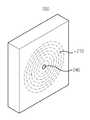
도 2는 본 발명의 일실시예인 무선 전력 수신 장치에 부착된 자계 센서의 위치를 설명하기 위한 개념도.
도 3은 본 발명의 일실시예인, 무선 전력 전송 장치에서 무선 전력 제어 방법을 설명하기 위한 흐름도.1 is a block diagram of a wireless power transmission system according to an embodiment of the present invention.
2 is a conceptual diagram illustrating a position of a magnetic field sensor attached to a wireless power receiver according to an embodiment of the present invention.
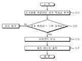
Figure 3 is a flow chart for explaining a wireless power control method in an embodiment of the present invention, a wireless power transmission device.
이하, 본 발명과 관련된 무선 전력 수신 장치 및 그 전력 제어 방법에 대하여 도면을 참조하여 보다 상세하게 설명한다. 이하의 설명에서 사용되는 구성요소에 대한 접미사 "모듈" 및 "부"는 명세서 작성의 용이함만이 고려되어 부여되거나 혼용되는 것으로서, 그 자체로 서로 구별되는 의미 또는 역할을 갖는 것은 아니다.
Hereinafter, a wireless power receiver and a power control method thereof according to the present invention will be described in detail with reference to the accompanying drawings. The suffix "module" and " part "for the components used in the following description are given or mixed in consideration of ease of specification, and do not have their own meaning or role.
도 1은 본 발명의 일실시예인 무선 전력 전송 시스템의 블록 구성도이다. 도시된 바와 같이, 본 발명의 일실시예인 무선 전력 전송 시스템은, 무선 전력 전송 장치(100)와 무선 전력 수신 장치(200)를 포함한다. 즉, 전자기 유도 방식에 의해, 무선 전력 전송 장치(100)가 무선 전력 신호를 무선 전력 수신 장치(200)로 전송하면, 이 전력 신호를 수신한 무선 전력 수신 장치(200)는 상기 무선 전력 신호의 전력으로 배터리를 충전하거나, 무선 전력 수신 장치(200)와 연결된 전자기기에 전원을 공급하게 된다.1 is a block diagram of a wireless power transmission system according to an embodiment of the present invention. As shown in the figure, a wireless power transmission system according to an embodiment of the present invention includes a wireless power transmission apparatus 100 and a wireless
이하에서는, 무선 전력 전송 장치(100)와 무선 전력 수신 장치(200)의 구성에 대하여 각각 설명하도록 한다.Hereinafter, the configurations of the wireless power transmitter 100 and the
본 발명의 일시시예인 무선 전력 전송 장치(100)는, 1차측 코어(110), 전송 제어부(120) 및 AC/DC 컨버터(130)를 포함한다. 여기서 1차측 코어(110)(1차측 코일)은 전력 신호를 전자기 유도 방식으로 전력 수신 장치(200)의 2차측 코어(210)에 전송하기 위한 장치로서, 본 실시예에서는 2개의 코일(즉, 제 1 서브 코일(111) 및 제 2 서브 코일(112))이 적용될 수 있다.A wireless power transmission apparatus 100, which is a temporary example of the present invention, includes a
다시 도 1을 참조하면, 상기 1차측 코어(110)을 제어하는 전송 제어부(120)는, 객체 감지부(121), 중앙제어부(122), 스위칭제어부(123), 구동드라이버(124) 및 직렬공진형컨버터(125) 포함할 수 있다.Referring back to FIG. 1, the
상기 객체 감지부(121)는 상기 1차측 코일인 1차측 코어(110)의 부하변화를 감지하고, 해당 부하변화가 무선 전력 수신 장치(200)에 의한 것인지를 판단할 뿐만 아니라(즉 아이디 확인부로서의 기능을 가짐), 무선 전력 수신 장치(200)로부터 전송된 충전 상태 신호를 필터링하여 처리하는 기능을 수행한다. 즉, 1차측 코어(110)을 통해 전송되는 아이디 호출 신호의 응답신호인 아이디 신호가 수신되면, 이를 필터링 하여 처리하고, 충전 중, 배터리 셀이나 충전 전압에 관한 정보를 포함하는 충전 상태 신호가 수신되면. 이를 필터링하여 처리하는 기능을 한다.The
상기 중앙 제어부(122)는 상기 객체 감지부(121)의 판단결과를 전송받아 확인하고, 1차측 코어(110)에서 수신되는 아이디 신호를 분석하여, 상기 1차측 코어(110)를 통해 무선 전력 신호를 송출하기 위한 전력 신호를 상기 구동 드라이버(124)로 전송하는 역할을 한다. 또한, 후술하는 1차측 코어로부터 충전 상태신호가 수신되면, 이에 기초하여 구동 드라이버(124)를 제어하여 무선 전력 신호를 변경하는 기능을 한다.The
상기 스위칭제어부(123)는 직렬 공진형 컨버터(125)와 제 1 서브 코일(111) 및 제 2 서브 코일(112)의 사이에 스위치의 스위칭동작을 제어하는 것이다. 본 발명에서는, 2개의 서브 코일이 이용되고 있으나, 본 발명은 이에 한정되지 않고, 하나의 코일이 적용되는 경우도 포함한다. 하나의 코일이 적용되는 경우, 상기 스위칭 제어부(123)가 불필요하게 된다.The
상기 구동 드라이버(124)는 중앙 제어부(122)의 제어를 통해 직렬 공진형 컨버터(125)의 동작을 제어하는 것이다.The
상기 직렬 공진형 컨버터(125)는 구동 드라이버(124)의 제어에 의해 송출하고자 하는 전력신호를 발생하기 위한 송출전원을 생성하여 상기 1차측 코어(110)로 공급하는 것이다. 다시 말해, 중앙 제어부(122)가 요구되는 전력값을 갖는 전력 신호의 송출을 위한 전력 제어 신호를 구동 드라이버(124)로 전송하면, 상기 구동 드라이버(124)는 전송된 전력제어신호에 대응하여 직렬 공진형 컨버터(125)의 동작을 제어하고, 상기 직렬 공진형 컨버터(125)는 구동 드라이버(124)의 제어에 의하여 요구되는 전력값에 대응하는 송출전원을 1차측 코어(110)에 인가함으로써, 요구되는 세기의 무선 전력 신호가 송출되도록 하는 것이다.The
또한, 상기 직렬 공진형 컨버터(125)는 구동 드라이버(124)의 제어에 의해 제 1 서브 코일(111) 및 제 2 서브 코일(112)을 통해 각각 제 1 객체 감지 신호와 제 2 객체 감지 신호를 발생하기 위한 전원을 공급하는 역할을 한다.In addition, the
AC/DC 컨버터(130)는 220V 또는 110V 의 교류 전원을 소정 전압의 직류 전원으로 변경하는 장치로서, 전술한 바와 같이, 상기 중앙 제어부(122)의 제어에 의해, 출력 전압값이 변경된다.
The AC /
그리고, 전력신호를 수신하여 전력을 공급받는 무선 전력 수신 장치(200)는, 상기 송출된 전력 신호에 의해 유도전력을 생성하는 2차측 코어(210), 유도된 전력을 정류하는 정류부(220), 정류된 전력으로 충전되는 배터리셀모듈(230), 상기 1차측 코어에 의해 발생되는 자기장을 감지하기 위한 자계 센서(240), 알람부(250) 그리고, 상기 2차측 코어(210), 정류부(220), 상기 배터리셀 모듈(230), 자계 센서(240) 및 알람부(250)를 제어하는 수신 제어부(260)를 포함한다. 본 발명의 무선 전력 수신 장치(200)는 배터리셀 모듈을 포함하는 패터리 팩일 수도 있고, 이 패터리 팩을 포함하는 이동 통신 단말기일 수도 있다.In addition, the
2차측 코어(210)는 무선 전력 전송 장치(100)의 1차측 코어로부터 전송되는 무선 전력 신호를 수신하기 위한 구성요소이다.The
정류부(220)는 상기 2차측 코어로부터 수신되는 무선 전력을 직류 전압으로 정류하며, 충전 개시 전까지는 충전전압으로 충전 상태를 유지하게 된다.The
배터리 셀 모듈(230)은 수신 제어부(240)의 제어를 받아 상기 정류부(220)로부터의 직류 전원을 통해 충전이 되는 충전 대상이 된다. 배터리 셀모듈(230) 대신에 PMP, MP3, 핸드폰등의 전자기기가 될 수도 있다. 한편, 상기 배터리셀 모듈(230)에는 과전압 및 과전류방지회로, 온도감지회로 등의 보호회로가 포함되어 구성되며, 또한, 배터리셀의 충전상태 등의 정보를 수집 및 처리하는 충전관리모듈이 포함된다.Under the control of the
자계 센서(240)는 상기 무선 전력 전송 장치(100)의 1차측 코어(110)에서 발생되는 자기장을 측정하기 위한 것이다. 이 자계 센서(240)로는 홀 아이씨(Hall IC) 센서가 이용될 수 있으며, 이는 무선 전력 수신 장치(200)의 주면에 설치될 수 있다. 이에 대해서는 도 2를 참조하여 설명하도록 한다.The
알람부(250)는 무선 전력 수신 장치(200)가 정상적으로 무선 전력 신호를 수신하지 못하게 되는 경우, 무선 전력 수신 불가를 나타내는 에러 데이터를 출력하기 위한 구성요소이다. 이러한 알람부(250)로는 스피커, 진동 모듈 등이 될 수 있다.The alarm unit 250 is an element for outputting error data indicating that the wireless power reception is impossible when the
수신 제어부(260)는 정류부(220)에서 충전된 전원의 전류를 제어하여 배터리셀모듈(230)로 적절한 전류가 흐르도록 하는 구성요소이다. 이 수신 제어부(240)의 구체적인 동작은 도 3를 참조하여 보다 상세하게 설명하도록 한다.
The
도 2는 본 발명의 일실시예인 무선 전력 수신 장치에 부착된 자계 센서(240)의 위치를 설명하기 위한 개념도이다. 도시된 바와 같이, 무선 전력 수신 장치(200)의 주면에는 2차측 코어(210)가 내장된다. 이 2차측 코어(210)는 원형 코일 또는 타원형 코일일 수 있다. 이 때, 자계 센서(240)은 상기 2차측 코어(210)의 중심점에 대응되는 상기 무선 전력 수신 장치(200)의 주면에 설치된다. 그러면, 상기 자계 센서(240)는 1차측 코어로부터의 자기장을 보다 정확하게 측정할 수 있게 되어, 이물질 감지뿐 아니라, 충전 정위치 확인에도 이용될 수 있다.2 is a conceptual diagram illustrating the position of the
또는, 자계센서(240)는 무선 전력 수신 장치(200)의 PCM(protective circuit module)(도면에 표시되지 않음)에 장착될 수 있다. 즉, 도 2와 달리, 자계 센서(240)가 무선 전력 수신 장치(200)의 회로 기판에 장착될 수 있음이 이해되어야 한다.
Alternatively, the
이하에서는 도 1 및 도 2에서 설명한 무선 전력 수신 장치에서의 전력 제어 방법에 대하여 도 3을 통해 보다 상세하게 설명하도록 한다.Hereinafter, the power control method in the wireless power receiver described with reference to FIGS. 1 and 2 will be described in more detail with reference to FIG. 3.
도 3은 본 발명의 일실시예인, 무선 전력 전송 장치에서 무선 전력 제어 방법을 설명하기 위한 흐름도이다. 도시된 바와 같이, 우선, 상기 무선 전력 수신 장치(200)에 설치된 자계 센서(240)를 통해, 무선 전력 전송 장치(100)의 1차측 코어(110)에 의해 형성되는 자기장을 측정하여 자계 측정값을 하다(S11).3 is a flowchart illustrating a method of controlling wireless power in a wireless power transmission apparatus according to an embodiment of the present invention. As shown, first, the magnetic field measurement value by measuring the magnetic field formed by the
상기 자계 센서(240)로부터 획득되는 자계 측정값이 기준 자계값보다 작은지 여부를 판단한다(S13). 만약 이물질이 없다면, 자계 센서(240)로부터 측정되는 자계 측정값은 기준 자계값과 동일하거나 크게 될 것이다. 그러나, 동전이나, 클립과 같은 이물질이 무선 전력 전송 장치(100)의 충전 위치 또는 그 근방에 위치하게 되면, 이 이물질이 상기 자계 측정값에 영향을 주게 되어, 그 값이 기준 자계값보다 작아지게 된다. 본 발명은 이러한 현상을 주목하여, 이를 통해 무선 충전 개시전 또는 무선 충전 중에 이물질을 감지하는 방식을 창안한 것이다.It is determined whether the magnetic field measurement value obtained from the
만약 자계 측정값이 기준 자계값보다 같거나 크면, 이물질이 감지되지 않은 것으로 판단하여 정상적으로 무선 충전 동작을 실행한다. 즉, 상기 무선 전력 수신 장치(200)의 배터리셀 모듈(230)에서 측정되는 충전 상태 신호에 기초하여, 무선 전력 변경 신호를 상기 무선 전력 전송 장치(100)로 전송한다. 만약, 상기 자계 센서(240)로부터 획득되는 자계 측정값이 기준 자계값보다 작고, 상기 무선 전력 전송 장치(100)와 통신이 가능한 경우, 상기 2차측 코어를 통해 상기 무선 전력 전송 장치(100)측으로 에러코드를 전송한다(S15). 만약 정상적인 통신이 불가능한 경우, 무선 전력 전송 장치(100)의 전송 제어부(120)는 무선 전력 신호의 발신을 정지한다. 상기 자계 센서(240)로부터 획득되는 자계 측정값이 기준 자계값보다 작은 경우, 이물질을 감지한 것으로 판단하고, 이에 따라 에러 코드를 발생함과 더불어, 상기 무선 전력 수신 장치(200)의 알람부(250)를 통해 무선 전력 수신 불가를 나타내는 에러 데이터를 출력할 수 있다(S17). 이 에러 데이터는 스피커나 진동모듈을 통해 출력될 수 있다.If the magnetic field measurement value is greater than or equal to the reference magnetic field value, it is determined that the foreign matter is not detected and the wireless charging operation is normally performed. That is, the wireless power change signal is transmitted to the wireless power transmitter 100 based on the charge state signal measured by the
상술한 구성을 가진 본 발명의 일실시예에 따르면, 무선 충전 중 또는 무선 충전 개시 전에 무선 전력 전송 장치와 무선 전력 수신 장치 사이에 존재할 수 있는 이물질을 감지할 수 있고, 이에 따라 무선 전력 전송 제어를 함으로써 무선 전력 전송 효율을 높일 수 있다.
According to an embodiment of the present invention having the above-described configuration, it is possible to detect foreign matter that may exist between the wireless power transmission apparatus and the wireless power reception apparatus during wireless charging or before the start of wireless charging, Thereby enhancing the wireless power transmission efficiency.
상기와 같이 설명된 무선 전력 수신 장치 및 그 전력 제어 방법은 상기 설명된 실시예들의 구성과 방법이 한정되게 적용될 수 있는 것이 아니라, 상기 실시예들은 다양한 변형이 이루어질 수 있도록 각 실시예들의 전부 또는 일부가 선택적으로 조합되어 구성될 수도 있다.
The above-described wireless power receiving apparatus and its power control method are not limited to the configuration and method of the above-described embodiments, but the embodiments can be applied to all or some of the embodiments May be selectively combined.
100 : 무선 전력 전송 장치
111 : 제 1 서브 코일
112 : 제 2 서브 코일
120 : 전송 제어부
121 : 객체 감지부
122 : 중앙 제어부
123 : 스위칭 제어부
124 : 구동 드라이버
125 : 직렬 공진형 컨버터
130 : 교류/직류 컨버터
200 : 무선 전력 수신 장치
210 : 2차측 코어
220 : 정류부
230 : 배터리셀 모듈
240 : 자계 센서
250 : 알람부
260 : 수신 제어부100: Wireless power transmission device
111: first sub coil
112: second sub coil
120:
121: object detection unit
122:
123:
124 drive driver
125: Series resonant converter
130: AC / DC converter
200: Wireless power receiving device
210: secondary side core
220: rectification part
230: battery cell module
240: magnetic field sensor
250: alarm unit
260: reception control unit
Claims (10)
Translated fromKorean상기 1차측 코어에서 상기 무선 전력 신호가 전송됨에 따라 발생되는 자기장을 감지하기 위한 자계 센서; 및
상기 자계 센서로부터 획득되는 자계 측정값이 기준 자계값보다 작고, 상기 무선 전력 전송 장치와 통신이 가능한 경우, 상기 2차측 코어를 통해 상기 무선 전력 전송 장치측으로 에러코드를 전송하는 수신 제어부를 포함하는, 무선 전력 수신 장치.
A secondary side core for receiving a wireless power signal from a primary side core of the wireless power transfer apparatus;
A magnetic field sensor for detecting a magnetic field generated as the wireless power signal is transmitted from the primary core; And
If the magnetic field measurement value obtained from the magnetic field sensor is smaller than the reference magnetic field value, and the communication with the wireless power transmission device is possible, including a reception control unit for transmitting an error code to the wireless power transmission device through the secondary side core, Wireless power receiver.
상기 자계 센서는, 홀 아이씨(Hall IC) 센서인, 무선 전력 수신 장치.
The method of claim 1,
The magnetic field sensor is a Hall IC sensor.
상기 자계 센서는 상기 무선 전력 수신 장치의 주면에 설치되는, 무선 전력 수신 장치.
The method of claim 1,
The magnetic field sensor is installed on the main surface of the wireless power receiver.
알람부를 더 포함하고,
상기 수신 제어부는,
상기 자계 센서로부터 획득되는 자계 측정값이 기준 자계값보다 작은 경우, 상기 알람부를 통해 무선 전력 수신 불가를 나타내는 에러 데이터를 출력하는, 무선 전력 수신 장치.
The method of claim 1,
It further includes an alarm unit,
The reception control unit,
And outputting error data indicating that wireless power reception is not possible through the alarm unit when the magnetic field measurement value obtained from the magnetic field sensor is smaller than a reference magnetic field value.
배터리를 더 포함하고,
상기 수신 제어부는,
상기 배터리에서 측정되는 충전 상태 신호에 기초하여, 무선 전력 변경 신호를 상기 무선 전력 전송 장치로 전송하는, 무선 전력 수신 장치.
The method of claim 1,
Further includes a battery,
The reception control unit,
And a wireless power change signal is transmitted to the wireless power transmitter based on the charge state signal measured by the battery.
상기 무선 전력 수신 장치에 설치된 자계 센서를 통해, 무선 전력 전송 장치의 1차측 코어에서 무선 전력 신호가 전송됨에 따라 형성되는 자기장을 자계 센서로 측정하여 자계 측정값을 획득하는 단계; 및
상기 자계 센서로부터 획득되는 자계 측정값이 기준 자계값보다 작고, 상기 무선 전력 전송 장치와 통신이 가능한 경우, 상기 무선 전력 수신 장치의 2차측 코어를 통해 상기 무선 전력 전송 장치측으로 에러코드를 전송하는 단계를 포함하는, 무선 전력 수신 장치에서의 전력 수신 제어 방법.
A power reception control method in a wireless power receiver,
Obtaining a magnetic field measurement value by measuring, by a magnetic field sensor, a magnetic field formed as a wireless power signal is transmitted from a primary core of the wireless power transmitter through a magnetic field sensor installed in the wireless power receiver; And
Transmitting an error code to the wireless power transmitter through the secondary core of the wireless power receiver when the magnetic field measured value obtained from the magnetic field sensor is smaller than a reference magnetic field and is capable of communication with the wireless power transmitter. A power reception control method in a wireless power receiver comprising a.
상기 자계 센서는, 홀 아이씨(Hall IC) 센서인, 무선 전력 수신 장치에서의 전력 수신 제어 방법.
The method according to claim 6,
The magnetic field sensor is a Hall IC sensor, the power reception control method in a wireless power receiver.
상기 자계 센서는 상기 무선 전력 수신 장치의 주면에 설치되는, 무선 전력 수신 장치에서의 전력 수신 제어 방법.
The method according to claim 6,
The magnetic field sensor is installed on the main surface of the wireless power receiver, power reception control method in a wireless power receiver.
상기 자계 센서로부터 획득되는 자계 측정값이 기준 자계값보다 작은 경우, 상기 무선 전력 수신 장치의 알람부를 통해 무선 전력 수신 불가를 나타내는 에러 데이터를 출력하는 단계를 더 포함하는, 무선 전력 수신 장치에서의 전력 수신 제어 방법.
The method according to claim 6,
If the magnetic field measurement value obtained from the magnetic field sensor is smaller than a reference magnetic field value, outputting error data indicating that wireless power reception is not possible through an alarm unit of the wireless power receiver, the power in the wireless power receiver Receive control method.
상기 자계 센서로부터 획득되는 자계 측정값이 기준 자계값보다 크면, 상기 무선 전력 수신 장치의 배터리에서 측정되는 충전 상태 신호에 기초하여, 무선 전력 변경 신호를 상기 무선 전력 전송 장치로 전송하는 단계를 더 포함하는, 무선 전력 수신 장치에서의 전력 수신 제어 방법.The method according to claim 6,
If a magnetic field measurement value obtained from the magnetic field sensor is greater than a reference magnetic field value, transmitting a wireless power change signal to the wireless power transmitter based on a state of charge signal measured by a battery of the wireless power receiver. A power reception control method in a wireless power receiver.
Priority Applications (3)
| Application Number | Priority Date | Filing Date | Title |
|---|---|---|---|
| KR1020110026057AKR101246693B1 (en) | 2011-03-23 | 2011-03-23 | Wireless power receiving device and power control method thereof |
| CN201210075358.1ACN102694425B (en) | 2011-03-23 | 2012-03-21 | Wireless power receiving apparatus and power control method thereof |
| US13/428,226US9479005B2 (en) | 2011-03-23 | 2012-03-23 | Wireless power receiving apparatus and power control method thereof related applications |
Applications Claiming Priority (1)
| Application Number | Priority Date | Filing Date | Title |
|---|---|---|---|
| KR1020110026057AKR101246693B1 (en) | 2011-03-23 | 2011-03-23 | Wireless power receiving device and power control method thereof |
Publications (2)
| Publication Number | Publication Date |
|---|---|
| KR20120108341A KR20120108341A (en) | 2012-10-05 |
| KR101246693B1true KR101246693B1 (en) | 2013-03-21 |
Family
ID=46859737
Family Applications (1)
| Application Number | Title | Priority Date | Filing Date |
|---|---|---|---|
| KR1020110026057AActiveKR101246693B1 (en) | 2011-03-23 | 2011-03-23 | Wireless power receiving device and power control method thereof |
Country Status (3)
| Country | Link |
|---|---|
| US (1) | US9479005B2 (en) |
| KR (1) | KR101246693B1 (en) |
| CN (1) | CN102694425B (en) |
Families Citing this family (19)
| Publication number | Priority date | Publication date | Assignee | Title |
|---|---|---|---|---|
| JP5748628B2 (en)* | 2011-09-28 | 2015-07-15 | 株式会社アドバンテスト | Wireless power receiving device and wireless power feeding device |
| CN202696123U (en)* | 2012-03-31 | 2013-01-23 | 中兴通讯股份有限公司 | Charging protection circuit |
| US9722448B2 (en)* | 2012-09-07 | 2017-08-01 | Qualcomm Incorporated | Protection device and method for power transmitter |
| EP2909917B1 (en)* | 2012-10-16 | 2020-11-11 | Koninklijke Philips N.V. | Wireless inductive power transfer |
| KR102080096B1 (en) | 2012-10-19 | 2020-04-14 | 삼성전자주식회사 | Wireless power transmitter, wireless power receiver and method for transmitting a emergency information in wireless power network |
| EP2909912B1 (en) | 2012-10-19 | 2022-08-10 | WiTricity Corporation | Foreign object detection in wireless energy transfer systems |
| JP6010491B2 (en)* | 2013-03-15 | 2016-10-19 | 株式会社東芝 | Resonator and wireless power transmission device |
| US9608470B2 (en) | 2013-11-27 | 2017-03-28 | Nxp B.V. | Bank card presence detection to avoid a wireless charger demagnetizing a bank card |
| CN104237954B (en)* | 2014-09-10 | 2017-09-05 | 青岛众海汇智能源科技有限责任公司 | The foreign matter detecting method and device of radio energy transmission system |
| US10486538B2 (en) | 2015-11-02 | 2019-11-26 | Hyundai America Technical Center, Inc. | Electromagnetic field controlling system and method for vehicle wireless charging system |
| CN105216650A (en)* | 2015-11-06 | 2016-01-06 | 浙江绿源电动车有限公司 | Battery-driven car and charging unit |
| JP6588867B2 (en)* | 2016-06-24 | 2019-10-09 | 株式会社ダイヘン | Non-contact power transmission system and magnetic field detection device |
| EP3493363B1 (en) | 2016-07-29 | 2020-07-01 | Sony Semiconductor Solutions Corporation | Power-supplying device |
| WO2018048312A1 (en) | 2016-09-06 | 2018-03-15 | Powerbyproxi Limited | An inductive power transmitter |
| WO2019117140A1 (en)* | 2017-12-11 | 2019-06-20 | パナソニックIpマネジメント株式会社 | Wireless power transmission system, power transmitting device, and power receiving device |
| KR102830213B1 (en)* | 2019-11-18 | 2025-07-07 | 삼성전자주식회사 | Electronic device for wirelessly transmitting power and method for operating the same |
| US11469625B2 (en)* | 2019-11-18 | 2022-10-11 | Samsung Electronics Co., Ltd. | Electronic device for wirelessly transmitting power and method of operating the same |
| DE112020006434T5 (en) | 2020-03-03 | 2022-10-20 | Microchip Technology Incorporated | DETECTION OF LOW POWER OBJECTS IN WIRELESS MULTI-COIL CHARGING SYSTEMS AND RELATED SYSTEMS, METHODS AND DEVICES |
| JP7715659B2 (en)* | 2022-03-10 | 2025-07-30 | トヨタ自動車株式会社 | Abnormality diagnosis system and abnormality determination method |
Citations (4)
| Publication number | Priority date | Publication date | Assignee | Title |
|---|---|---|---|---|
| JP2004208383A (en)* | 2002-12-25 | 2004-07-22 | Aichi Electric Co Ltd | Non-contact power supply |
| JP2006060909A (en)* | 2004-08-19 | 2006-03-02 | Seiko Epson Corp | Non-contact power transmission device |
| KR20090089941A (en)* | 2008-02-20 | 2009-08-25 | 정춘길 | Contactless charging system and its charging control method |
| JP2010130729A (en) | 2008-11-25 | 2010-06-10 | Canon Inc | Charging equipment, transmission equipment, and noncontact charging system |
Family Cites Families (23)
| Publication number | Priority date | Publication date | Assignee | Title |
|---|---|---|---|---|
| US6885302B2 (en)* | 2002-07-31 | 2005-04-26 | Itron Electricity Metering, Inc. | Magnetic field sensing for tamper identification |
| US7521890B2 (en)* | 2005-12-27 | 2009-04-21 | Power Science Inc. | System and method for selective transfer of radio frequency power |
| US7948208B2 (en)* | 2006-06-01 | 2011-05-24 | Mojo Mobility, Inc. | Power source, charging system, and inductive receiver for mobile devices |
| JP5300187B2 (en)* | 2006-09-07 | 2013-09-25 | 三洋電機株式会社 | Pack battery charged by magnetic induction |
| WO2008125621A1 (en)* | 2007-04-13 | 2008-10-23 | Alert Metalguard Aps | A method, a device and a system for preventing false alarms in a theft-preventing system |
| JP4743173B2 (en)* | 2007-06-29 | 2011-08-10 | セイコーエプソン株式会社 | Power transmission control device, power transmission device, non-contact power transmission system, and electronic device |
| KR100819753B1 (en)* | 2007-07-13 | 2008-04-08 | 주식회사 한림포스텍 | Contactless charging system for battery pack solution and its control method |
| WO2009041058A1 (en)* | 2007-09-27 | 2009-04-02 | Panasonic Corporation | Electronic device, recharger and recharging system |
| WO2009069844A1 (en)* | 2007-11-30 | 2009-06-04 | Chun-Kil Jung | Multiple non-contact charging system of wireless power transmision and control method thereof |
| US8633616B2 (en)* | 2007-12-21 | 2014-01-21 | Cynetic Designs Ltd. | Modular pocket with inductive power and data |
| US8791600B2 (en)* | 2007-12-21 | 2014-07-29 | Roger J. Soar | Vehicle seat inductive charger and data transmitter |
| US8446046B2 (en)* | 2008-10-03 | 2013-05-21 | Access Business Group International Llc | Power system |
| CN201349139Y (en)* | 2008-11-27 | 2009-11-18 | 比亚迪股份有限公司 | Induction type wireless charging device |
| WO2010096367A1 (en)* | 2009-02-17 | 2010-08-26 | Allegro Microsystems, Inc. | Circuits and methods for generating a self-test of a magnetic field sensor |
| JP5353376B2 (en)* | 2009-03-31 | 2013-11-27 | 富士通株式会社 | Wireless power device and wireless power receiving method |
| AU2010234396A1 (en)* | 2009-04-08 | 2011-10-27 | Access Business Group International Llc | Selectable coil array |
| DE102009033236A1 (en)* | 2009-07-14 | 2011-01-20 | Conductix-Wampfler Ag | Device for inductive transmission of electrical energy |
| CA2768397A1 (en)* | 2009-07-24 | 2011-01-27 | Access Business Group International Llc | Power supply |
| US9787364B2 (en)* | 2011-01-20 | 2017-10-10 | Triune Ip, Llc | Multi-use wireless power and data system |
| EP2529469B1 (en)* | 2010-01-27 | 2017-06-14 | Cynetic Designs Ltd | Modular pocket with inductive power and data |
| JP4996722B2 (en)* | 2010-06-30 | 2012-08-08 | 株式会社東芝 | Power transmission system and power transmission device |
| CN101950999A (en)* | 2010-09-21 | 2011-01-19 | 宇龙计算机通信科技(深圳)有限公司 | Wireless charging method, wireless charging receiving device and mobile terminal |
| US8566651B2 (en)* | 2010-11-15 | 2013-10-22 | LifeSafety Power Inc. | Apparatus and method for a networked power management system for security and life safety applications |
- 2011
- 2011-03-23KRKR1020110026057Apatent/KR101246693B1/enactiveActive
- 2012
- 2012-03-21CNCN201210075358.1Apatent/CN102694425B/enactiveActive
- 2012-03-23USUS13/428,226patent/US9479005B2/enactiveActive
Patent Citations (4)
| Publication number | Priority date | Publication date | Assignee | Title |
|---|---|---|---|---|
| JP2004208383A (en)* | 2002-12-25 | 2004-07-22 | Aichi Electric Co Ltd | Non-contact power supply |
| JP2006060909A (en)* | 2004-08-19 | 2006-03-02 | Seiko Epson Corp | Non-contact power transmission device |
| KR20090089941A (en)* | 2008-02-20 | 2009-08-25 | 정춘길 | Contactless charging system and its charging control method |
| JP2010130729A (en) | 2008-11-25 | 2010-06-10 | Canon Inc | Charging equipment, transmission equipment, and noncontact charging system |
Also Published As
| Publication number | Publication date |
|---|---|
| US9479005B2 (en) | 2016-10-25 |
| KR20120108341A (en) | 2012-10-05 |
| US20120242163A1 (en) | 2012-09-27 |
| CN102694425A (en) | 2012-09-26 |
| CN102694425B (en) | 2015-07-22 |
Similar Documents
| Publication | Publication Date | Title |
|---|---|---|
| KR101246693B1 (en) | Wireless power receiving device and power control method thereof | |
| JP6401730B2 (en) | Power transmission control method and wireless power transmission apparatus in wireless power transmission apparatus | |
| KR102023068B1 (en) | Wireless power transmitting device and method for controlling to transmit wireless power signal in wireless power transmitting device | |
| CN106961147B (en) | Wireless power transmission system with overheat protection function and method | |
| US20120313579A1 (en) | Contactless power supply device and contactless charging system | |
| KR102154306B1 (en) | Wireless power transmission device which enables to simultaneously charge | |
| CN103178622A (en) | Signal detection device and wireless power transmission device having same | |
| KR20120109067A (en) | Power control method and wireless power transfer assembly in wireless power transfer assembly | |
| KR100928439B1 (en) | Solid-state power charging station with a flat spiral core power transformer PC core | |
| KR101742553B1 (en) | Method for controlling power transmission in wireless power transmission apparatus and wireless power transmission apparatus thereof | |
| KR101213089B1 (en) | Method for controlling received power in wireless power receiving device and wireless power receiving device thereof | |
| KR101261338B1 (en) | Charger non-contact and contact charger and controlling method thereof | |
| KR102230682B1 (en) | Wireless power transmission device which enables to simultaneously charge | |
| KR101046659B1 (en) | Battery Wireless Charging Device for Mobile Devices | |
| KR101254258B1 (en) | Method for controlling wireles power transmission in wireless power transmission device and wireless power transmission device using the same | |
| KR101213087B1 (en) | Method for controlling received power in wireless power receiving device and wireless power receiving device thereof | |
| KR20210031668A (en) | Wireless power transmission device which enables to simultaneously charge | |
| KR100915842B1 (en) | Contactless power charging station equipped with a planar spiral core PTS core and its control method |
Legal Events
| Date | Code | Title | Description |
|---|---|---|---|
| A201 | Request for examination | ||
| PA0109 | Patent application | St.27 status event code:A-0-1-A10-A12-nap-PA0109 | |
| PA0201 | Request for examination | St.27 status event code:A-1-2-D10-D11-exm-PA0201 | |
| P11-X000 | Amendment of application requested | St.27 status event code:A-2-2-P10-P11-nap-X000 | |
| P13-X000 | Application amended | St.27 status event code:A-2-2-P10-P13-nap-X000 | |
| R15-X000 | Change to inventor requested | St.27 status event code:A-3-3-R10-R15-oth-X000 | |
| R16-X000 | Change to inventor recorded | St.27 status event code:A-3-3-R10-R16-oth-X000 | |
| D13-X000 | Search requested | St.27 status event code:A-1-2-D10-D13-srh-X000 | |
| D14-X000 | Search report completed | St.27 status event code:A-1-2-D10-D14-srh-X000 | |
| PE0902 | Notice of grounds for rejection | St.27 status event code:A-1-2-D10-D21-exm-PE0902 | |
| AMND | Amendment | ||
| P11-X000 | Amendment of application requested | St.27 status event code:A-2-2-P10-P11-nap-X000 | |
| P13-X000 | Application amended | St.27 status event code:A-2-2-P10-P13-nap-X000 | |
| PG1501 | Laying open of application | St.27 status event code:A-1-1-Q10-Q12-nap-PG1501 | |
| R17-X000 | Change to representative recorded | St.27 status event code:A-3-3-R10-R17-oth-X000 | |
| E601 | Decision to refuse application | ||
| PE0601 | Decision on rejection of patent | St.27 status event code:N-2-6-B10-B15-exm-PE0601 | |
| R17-X000 | Change to representative recorded | St.27 status event code:A-3-3-R10-R17-oth-X000 | |
| AMND | Amendment | ||
| P11-X000 | Amendment of application requested | St.27 status event code:A-2-2-P10-P11-nap-X000 | |
| P13-X000 | Application amended | St.27 status event code:A-2-2-P10-P13-nap-X000 | |
| PX0901 | Re-examination | St.27 status event code:A-2-3-E10-E12-rex-PX0901 | |
| PX0701 | Decision of registration after re-examination | St.27 status event code:A-3-4-F10-F13-rex-PX0701 | |
| X701 | Decision to grant (after re-examination) | ||
| GRNT | Written decision to grant | ||
| PR0701 | Registration of establishment | St.27 status event code:A-2-4-F10-F11-exm-PR0701 | |
| PR1002 | Payment of registration fee | St.27 status event code:A-2-2-U10-U11-oth-PR1002 Fee payment year number:1 | |
| PG1601 | Publication of registration | St.27 status event code:A-4-4-Q10-Q13-nap-PG1601 | |
| PN2301 | Change of applicant | St.27 status event code:A-5-5-R10-R13-asn-PN2301 St.27 status event code:A-5-5-R10-R11-asn-PN2301 | |
| PN2301 | Change of applicant | St.27 status event code:A-5-5-R10-R13-asn-PN2301 St.27 status event code:A-5-5-R10-R11-asn-PN2301 | |
| L13-X000 | Limitation or reissue of ip right requested | St.27 status event code:A-2-3-L10-L13-lim-X000 | |
| U15-X000 | Partial renewal or maintenance fee paid modifying the ip right scope | St.27 status event code:A-4-4-U10-U15-oth-X000 | |
| FPAY | Annual fee payment | Payment date:20160104 Year of fee payment:4 | |
| PR1001 | Payment of annual fee | St.27 status event code:A-4-4-U10-U11-oth-PR1001 Fee payment year number:4 | |
| PR1001 | Payment of annual fee | St.27 status event code:A-4-4-U10-U11-oth-PR1001 Fee payment year number:5 | |
| PN2301 | Change of applicant | St.27 status event code:A-5-5-R10-R11-asn-PN2301 | |
| PN2301 | Change of applicant | St.27 status event code:A-5-5-R10-R14-asn-PN2301 | |
| PR1001 | Payment of annual fee | St.27 status event code:A-4-4-U10-U11-oth-PR1001 Fee payment year number:6 | |
| PR1001 | Payment of annual fee | St.27 status event code:A-4-4-U10-U11-oth-PR1001 Fee payment year number:7 | |
| P22-X000 | Classification modified | St.27 status event code:A-4-4-P10-P22-nap-X000 | |
| P22-X000 | Classification modified | St.27 status event code:A-4-4-P10-P22-nap-X000 | |
| PR1001 | Payment of annual fee | St.27 status event code:A-4-4-U10-U11-oth-PR1001 Fee payment year number:8 | |
| PR1001 | Payment of annual fee | St.27 status event code:A-4-4-U10-U11-oth-PR1001 Fee payment year number:9 | |
| P22-X000 | Classification modified | St.27 status event code:A-4-4-P10-P22-nap-X000 | |
| PR1001 | Payment of annual fee | St.27 status event code:A-4-4-U10-U11-oth-PR1001 Fee payment year number:10 | |
| PR1001 | Payment of annual fee | St.27 status event code:A-4-4-U10-U11-oth-PR1001 Fee payment year number:11 | |
| P22-X000 | Classification modified | St.27 status event code:A-4-4-P10-P22-nap-X000 | |
| PR1001 | Payment of annual fee | St.27 status event code:A-4-4-U10-U11-oth-PR1001 Fee payment year number:12 | |
| PR1001 | Payment of annual fee | St.27 status event code:A-4-4-U10-U11-oth-PR1001 Fee payment year number:13 |