KR101245145B1 - Portable ultrasonic diagnostic apparatus - Google Patents
Portable ultrasonic diagnostic apparatusDownload PDFInfo
- Publication number
- KR101245145B1 KR101245145B1KR20110066162AKR20110066162AKR101245145B1KR 101245145 B1KR101245145 B1KR 101245145B1KR 20110066162 AKR20110066162 AKR 20110066162AKR 20110066162 AKR20110066162 AKR 20110066162AKR 101245145 B1KR101245145 B1KR 101245145B1
- Authority
- KR
- South Korea
- Prior art keywords
- user
- main body
- ultrasound
- ultrasound image
- portable
- Prior art date
- Legal status (The legal status is an assumption and is not a legal conclusion. Google has not performed a legal analysis and makes no representation as to the accuracy of the status listed.)
- Active
Links
Images


Classifications
- A—HUMAN NECESSITIES
- A61—MEDICAL OR VETERINARY SCIENCE; HYGIENE
- A61B—DIAGNOSIS; SURGERY; IDENTIFICATION
- A61B8/00—Diagnosis using ultrasonic, sonic or infrasonic waves
- A61B8/13—Tomography
- A61B8/14—Echo-tomography
- A—HUMAN NECESSITIES
- A61—MEDICAL OR VETERINARY SCIENCE; HYGIENE
- A61B—DIAGNOSIS; SURGERY; IDENTIFICATION
- A61B8/00—Diagnosis using ultrasonic, sonic or infrasonic waves
- A61B8/44—Constructional features of the ultrasonic, sonic or infrasonic diagnostic device
- A61B8/4427—Device being portable or laptop-like
- A—HUMAN NECESSITIES
- A61—MEDICAL OR VETERINARY SCIENCE; HYGIENE
- A61B—DIAGNOSIS; SURGERY; IDENTIFICATION
- A61B8/00—Diagnosis using ultrasonic, sonic or infrasonic waves
- A61B8/46—Ultrasonic, sonic or infrasonic diagnostic devices with special arrangements for interfacing with the operator or the patient
- A61B8/461—Displaying means of special interest
- A61B8/462—Displaying means of special interest characterised by constructional features of the display
- A—HUMAN NECESSITIES
- A61—MEDICAL OR VETERINARY SCIENCE; HYGIENE
- A61B—DIAGNOSIS; SURGERY; IDENTIFICATION
- A61B8/00—Diagnosis using ultrasonic, sonic or infrasonic waves
- A61B8/46—Ultrasonic, sonic or infrasonic diagnostic devices with special arrangements for interfacing with the operator or the patient
- A61B8/461—Displaying means of special interest
- A61B8/463—Displaying means of special interest characterised by displaying multiple images or images and diagnostic data on one display
- A—HUMAN NECESSITIES
- A61—MEDICAL OR VETERINARY SCIENCE; HYGIENE
- A61B—DIAGNOSIS; SURGERY; IDENTIFICATION
- A61B8/00—Diagnosis using ultrasonic, sonic or infrasonic waves
- A61B8/46—Ultrasonic, sonic or infrasonic diagnostic devices with special arrangements for interfacing with the operator or the patient
- A61B8/461—Displaying means of special interest
- A61B8/466—Displaying means of special interest adapted to display 3D data
- A—HUMAN NECESSITIES
- A61—MEDICAL OR VETERINARY SCIENCE; HYGIENE
- A61B—DIAGNOSIS; SURGERY; IDENTIFICATION
- A61B8/00—Diagnosis using ultrasonic, sonic or infrasonic waves
- A61B8/46—Ultrasonic, sonic or infrasonic diagnostic devices with special arrangements for interfacing with the operator or the patient
- A61B8/467—Ultrasonic, sonic or infrasonic diagnostic devices with special arrangements for interfacing with the operator or the patient characterised by special input means
- A61B8/469—Ultrasonic, sonic or infrasonic diagnostic devices with special arrangements for interfacing with the operator or the patient characterised by special input means for selection of a region of interest
- A—HUMAN NECESSITIES
- A61—MEDICAL OR VETERINARY SCIENCE; HYGIENE
- A61B—DIAGNOSIS; SURGERY; IDENTIFICATION
- A61B8/00—Diagnosis using ultrasonic, sonic or infrasonic waves
- A61B8/52—Devices using data or image processing specially adapted for diagnosis using ultrasonic, sonic or infrasonic waves
- A61B8/5215—Devices using data or image processing specially adapted for diagnosis using ultrasonic, sonic or infrasonic waves involving processing of medical diagnostic data
- A—HUMAN NECESSITIES
- A61—MEDICAL OR VETERINARY SCIENCE; HYGIENE
- A61B—DIAGNOSIS; SURGERY; IDENTIFICATION
- A61B8/00—Diagnosis using ultrasonic, sonic or infrasonic waves
- A61B8/54—Control of the diagnostic device
- G—PHYSICS
- G06—COMPUTING OR CALCULATING; COUNTING
- G06F—ELECTRIC DIGITAL DATA PROCESSING
- G06F3/00—Input arrangements for transferring data to be processed into a form capable of being handled by the computer; Output arrangements for transferring data from processing unit to output unit, e.g. interface arrangements
- G06F3/01—Input arrangements or combined input and output arrangements for interaction between user and computer
- G06F3/03—Arrangements for converting the position or the displacement of a member into a coded form
- G06F3/033—Pointing devices displaced or positioned by the user, e.g. mice, trackballs, pens or joysticks; Accessories therefor
Landscapes
- Health & Medical Sciences (AREA)
- Life Sciences & Earth Sciences (AREA)
- Engineering & Computer Science (AREA)
- Physics & Mathematics (AREA)
- Surgery (AREA)
- Animal Behavior & Ethology (AREA)
- Radiology & Medical Imaging (AREA)
- Nuclear Medicine, Radiotherapy & Molecular Imaging (AREA)
- Biomedical Technology (AREA)
- Heart & Thoracic Surgery (AREA)
- Medical Informatics (AREA)
- Molecular Biology (AREA)
- Biophysics (AREA)
- Pathology (AREA)
- General Health & Medical Sciences (AREA)
- Public Health (AREA)
- Veterinary Medicine (AREA)
- General Engineering & Computer Science (AREA)
- Theoretical Computer Science (AREA)
- Computer Vision & Pattern Recognition (AREA)
- Computer Graphics (AREA)
- Human Computer Interaction (AREA)
- General Physics & Mathematics (AREA)
- Ultra Sonic Daignosis Equipment (AREA)
Abstract
Translated fromKoreanDescription
Translated fromKorean본 발명은 휴대형 초음파 진단기기에 관한 것으로, 보다 상세하게는 기기 후면에 입력장치를 구비하여 한 손으로 파지 및 조작이 가능한 휴대형 초음파 진단기기에 관한 것이다.The present invention relates to a portable ultrasonic diagnostic apparatus, and more particularly, to a portable ultrasonic diagnostic apparatus having an input device at the rear of the apparatus, which can be gripped and manipulated with one hand.
초음파 진단기기는 대상체의 체표로부터 체내의 소망 부위를 향하여 초음파 신호를 조사하고, 대상체로부터 반사되는 초음파 신호 즉, 초음파 에코신호의 정보를 이용하여 연부 조직의 단층이나 혈류에 관한 이미지를 무침습으로 얻는 기기이다. 이러한 초음파 진단기기는 X선 진단기기, CT스캐너(Computerized Tomography Scanner), MRI(Magnetic Resonance Image), 핵의학 진단기기 등의 다른 영상 진단기기와 비교할 때, 소형이고 저렴하며, 실시간으로 표시 가능하고, X선 등의 피폭이 없어 안전성이 높은 장점이 있다. 따라서 초음파 진단기기는 심장, 복부, 비뇨기 및 산부인과 진단을 위해 널리 이용되고 있다.The ultrasonic diagnostic apparatus irradiates ultrasonic signals from a body surface of the subject toward a desired area in the body, and acquires an image of soft tissue tomography or blood flow in a non-invasive manner using information of ultrasonic signals, that is, ultrasonic echo signals, reflected from the subject. Appliance. These ultrasound diagnostic devices are compact, inexpensive, and can be displayed in real time, compared to other imaging devices such as X-ray diagnostics, computerized tomography scanners, magnetic resonance images (MRIs), and nuclear medical diagnostics. There is no exposure to X-rays, so there is a high safety advantage. Therefore, the ultrasound diagnostic device is widely used for diagnosing the heart, abdomen, urinary gynecology.
초음파 진단기기는 그 크기가 크고 무게 또한 무겁기 때문에 특정 장소에 고정하여 사용하고 있으며, 소형의 초음파 진단기기라 하더라도 그 무게가 통상 10Kg 이상이어서 이동이 용이하지 않고 휴대가 불가능하였다. 한편, 응급실이나 수술실 또는 기타 초음파 진단이 필요한 임의의 장소에서는 초음파 진단기기를 자주 이동시켜야 하고 그 크기가 작아야 한다. 이러한 초음파 진단기기의 단점을 극복하기 위해 휴대 가능한 초음파 진단기기가 개발되고 있다.Ultrasonic diagnostic devices have a large size and a heavy weight, so they are fixed and used at specific places. Even a small ultrasonic diagnostic device has a weight of 10Kg or more, which is not easy to move and cannot be carried. On the other hand, in an emergency room, operating room, or any other place that requires an ultrasound diagnosis, the ultrasound diagnostic device should be moved frequently and its size should be small. In order to overcome the shortcomings of the ultrasonic diagnostic apparatus, a portable ultrasonic diagnostic apparatus has been developed.
휴대형 초음파 진단기기는 크기나 무게를 최소화하여 휴대가 가능하다는 장점이 있어 그 사용이 증가하고 있으나, 한 손에 초음파 프로브를 파지하여 대상체를 스캔해야 하기 때문에 휴대형 초음파 진단기기를 거치해야만 다른 한 손으로 기기 조작이 가능하다. 즉, 휴대형 초음파 진단기기를 거치하기 위한 거치대나 카트 등을 별도로 구비해야 하며, 한 손으로 휴대형 초음파 진단기기를 파지하고 파지한 손으로 기기를 조작할 수 없는 단점이 있다.Portable ultrasonic diagnostic devices have the advantage of being portable by minimizing the size and weight, but their use is increasing. However, the portable ultrasonic diagnostic device must be mounted on the other hand because the ultrasound probe must be held in one hand to scan the object. Device operation is possible. That is, a cradle or a cart for mounting the portable ultrasonic diagnostic apparatus must be separately provided, and there is a disadvantage in that the portable ultrasonic diagnostic apparatus is held with one hand and the device cannot be operated with the held hand.
기기의 본체 후면에 입력장치를 구비하여 한 손으로 파지 가능하고 파지한 손으로 조작이 가능한 휴대형 초음파 진단기기를 제안하고자 한다.The present invention proposes a portable ultrasonic diagnostic apparatus having an input device at the rear of the main body of the device, which can be held by one hand and operated by a held hand.
이를 위해 본 발명의 일 측면은 초음파 프로브를 구비한 휴대형 초음파 진단기기에 있어서, 본체; 및 사용자가 상기 본체를 파지하였을 때, 상기 본체의 후면에 위치한 손가락을 이용하여 사용자 명령 정보를 입력할 수 있도록 본체의 후면에 배치되는 입력장치를 포함한다.One aspect of the present invention for this purpose is a portable ultrasonic diagnostic apparatus having an ultrasonic probe, the main body; And an input device disposed at the rear of the main body so that when the user grips the main body, the user command information can be input using a finger located at the rear of the main body.
또한, 본체는 초음파 프로브로부터 수신되는 초음파 신호를 집속하여 프레임 데이터를 형성하는 빔 포머; 프레임 데이터를 디지털 신호 처리하여 초음파 데이터를 형성하는 초음파 데이터 형성부; 초음파 데이터를 이용하여 초음파 영상을 형성하는 초음파 영상 형성부; 사용자 명령 정보에 따라 초음파 영상 및 사용자 인터페이스의 디스플레이를 제어하는 제어부를 포함한다.In addition, the main body includes a beam former for focusing the ultrasonic signal received from the ultrasonic probe to form frame data; An ultrasonic data forming unit for digitally processing frame data to form ultrasonic data; An ultrasound image forming unit configured to form an ultrasound image using ultrasound data; And a controller for controlling the display of the ultrasound image and the user interface according to the user command information.
또한, 제어부는 사용자 명령 정보에 따라 사용자 인터페이스의 제공 및 초음파 영상의 최적화를 수행하도록 제어한다.In addition, the controller controls to provide a user interface and optimize an ultrasound image according to user command information.
또한, 입력장치는 트랙볼을 포함한다.The input device also includes a trackball.
또한, 트랙볼은 사용자 인터페이스의 요청 및 선택에 해당하는 상기 사용자 명령 정보를 입력한다.The trackball also inputs the user command information corresponding to a request and selection of a user interface.
또한, 트랙볼은 초음파 영상에서 관심영역의 설정 요청, 관심영역의 크기 조절 요청, 관심영역의 이동 요청에 해당하는 사용자 명령 정보를 입력한다.In addition, the trackball inputs user command information corresponding to a request for setting a region of interest, a request for adjusting the size of the region of interest, and a request for moving the region of interest in the ultrasound image.
또한, 입력장치는 트랙볼의 상하 또는 좌우에 마련되는 적어도 하나 이상의 버튼을 포함한다.In addition, the input device includes at least one button provided on the top, bottom, left and right sides of the trackball.
또한, 적어도 하나 이상의 버튼은 초음파 영상의 디스플레이 모드를 변경시키는 제1버튼 또는 초음파 영상의 디스플레이 화면을 정지시키는 제2버튼을 포함한다.The at least one button may include a first button for changing the display mode of the ultrasound image or a second button for stopping the display screen of the ultrasound image.
또한, 입력장치는 초음파 영상의 모드를 변경시키는 모드 체인지 버튼을 포함한다.The input device also includes a mode change button for changing a mode of the ultrasound image.
또한, 입력장치는 터치 패널을 포함한다.The input device also includes a touch panel.
또한, 입력장치는 본체의 후면에 착탈 가능하게 설치되는 착탈부재에 마련되며, 상기 착탈부재의 위치는 상기 사용자의 손의 크기에 맞추어 변경 가능하다.In addition, the input device is provided in a detachable member detachably installed at the rear of the main body, the position of the detachable member can be changed to match the size of the user's hand.
제안된 휴대형 초음파 진단기기에 따르면, 휴대형 초음파 진단기기의 본체 후면에 입력장치를 구비하여 한 손으로 휴대형 초음파 진단기기를 파지한 상태에서 조작이 가능하도록 한다. 이에 따라 휴대형 초음파 진단기기를 거치하기 위한 별도의 거치대나 카트가 필요없어 비용을 절감할 수 있고, 사용자가 휴대형 초음파 진단기기를 편리하게 파지할 수 있다.According to the proposed portable ultrasonic diagnostic apparatus, an input device is provided at the rear of the main body of the portable ultrasonic diagnostic apparatus so that the portable ultrasonic diagnostic apparatus can be operated while holding the portable ultrasonic diagnostic apparatus with one hand. Accordingly, a separate cradle or cart for mounting the portable ultrasound diagnostic apparatus is not required, thereby reducing costs, and the user may conveniently hold the portable ultrasound diagnostic apparatus.
또한, 사용자의 명령을 입력받기 위한 입력장치를 본체 후면에 배치하므로 휴대형 초음파 진단기기의 크기를 최소화하는데 제약이 없고, 스크린의 화면 전체에 초음파 영상을 디스플레이할 수 있어 초음파 영상의 시야를 넓힐 수 있기 때문에 사용자의 만족도를 높일 수 있다.In addition, since an input device for receiving a user's command is disposed at the rear of the main body, there is no limitation in minimizing the size of the portable ultrasound diagnostic device, and the ultrasound image can be displayed on the entire screen of the screen, thereby widening the field of view of the ultrasound image. Therefore, the user's satisfaction can be increased.
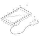
도 1은 본 발명의 실시예에 의한 휴대형 초음파 진단기기의 전면 구성도이다.
도 2는 본 발명의 실시예에 의한 휴대형 초음파 진단기기의 후면 구성도이다.
도 3a 내지 도 3c는 본 발명의 실시예에 의한 사용자의 입력 방식을 나타내는 예시도이다.
도 4는 본 발명의 실시예에 의한 표시부의 디스플레이 영역을 나타내는 예시도이다.
도 5는 본 발명의 실시예에 의한 본체의 구성 블록도이다.
도 6은 본 발명의 실시예에 의한 휴대형 초음파 진단기기에서 사용자 인터페이스를 제공하는 제어부의 동작 방법을 나타낸 동작 순서도이다.
도 7은 본 발명의 다른 실시예에 의한 휴대형 초음파 진단기기의 후면 구성도이다.
도 8은 본 발명의 또 다른 실시예에 의한 휴대형 초음파 진단기기의 후면 구성도이다.
도 9는 도 8의 구성에 의해 트랙볼의 위치를 변경하는 상태를 나타낸 도면이다.
도 10은 본 발명의 또 다른 실시예에 의한 휴대형 초음파 진단기기의 후면 구성도이다.1 is a front configuration diagram of a portable ultrasound diagnostic apparatus according to an embodiment of the present invention.
2 is a rear configuration diagram of a portable ultrasound diagnostic apparatus according to an embodiment of the present invention.
3A to 3C are exemplary views illustrating a user input method according to an embodiment of the present invention.
4 is an exemplary view illustrating a display area of a display unit according to an exemplary embodiment of the present invention.
5 is a block diagram of a main body according to an embodiment of the present invention.
6 is a flowchart illustrating an operation method of a controller providing a user interface in a portable ultrasound diagnostic apparatus according to an exemplary embodiment of the present invention.
7 is a rear configuration diagram of a portable ultrasound diagnostic apparatus according to another embodiment of the present invention.
8 is a rear configuration diagram of a portable ultrasound diagnostic apparatus according to another embodiment of the present invention.
9 is a view showing a state of changing the position of the track ball by the configuration of FIG.
10 is a rear configuration diagram of a portable ultrasound diagnostic apparatus according to another embodiment of the present invention.
이하, 본 발명의 실시예를 첨부된 도면을 참조하여 상세히 설명한다.Hereinafter, embodiments of the present invention will be described in detail with reference to the accompanying drawings.
도 1은 본 발명의 실시예에 의한 휴대형 초음파 진단기기의 전면 구성도이고, 도 2는 본 발명의 실시예에 의한 휴대형 초음파 진단기기의 후면 구성도이다.1 is a front configuration diagram of a portable ultrasound diagnostic apparatus according to an embodiment of the present invention, Figure 2 is a rear configuration diagram of a portable ultrasound diagnostic apparatus according to an embodiment of the present invention.
도 1 및 도 2에서, 휴대형 초음파 진단기기(10)는 대략 직육면체의 형상을 가지며 외관을 형성하는 본체(20)와, 본체(20)의 전면에 설치되어 휴대형 초음파 진단기기(10)의 각종 진단 정보를 초음파 영상으로 디스플레이하는 표시부(30)와, 본체(20)의 후면에 설치되어 사용자로부터 휴대형 초음파 진단기기(10)의 각종 조작 명령을 입력받는 입력장치(40)를 포함한다.1 and 2, the portable ultrasound
한편, 휴대형 초음파 진단기기(10)는 초음파 신호를 대상체(예를 들어, 간, 신장, 췌장, 심장 등의 신체부위)에 송신하고, 대상체로부터 반사되는 초음파 신호(즉, 초음파 에코신호)를 수신하여 전기적 신호로 변환하는 변환 소자(transducer element)를 구비한 초음파 프로브(50)를 더 포함한다. 초음파 프로브(50)는 본체(20)와 유선 또는 무선으로 연결될 수 있다.Meanwhile, the portable ultrasound
본체(20)는 사용자의 한 손으로 파지 가능한 크기 및 무게(예를 들어, 1㎏ 이하)를 가지며, 초음파 프로브(50)로부터 초음파 신호를 수신하고 수신된 초음파 신호를 이용하여 2차원 또는 3차원의 초음파 영상을 형성한다.The
또한, 본체(20)는 휴대형 초음파 진단기기(10)를 구동하기 위한 전력을 내장 배터리 또는 외부 전원 공급부로부터 공급받아 동작한다.In addition, the
또한, 본체(20)는 초음파 프로브(50)의 일단에 구비된 커넥터와 연결되는 연결부를 포함하고, 이 연결부를 통해 초음파 프로브(50)와 신호를 송수신한다.In addition, the
표시부(30)는 LED(Light Emitting Diode), LCD(Liquid Crystal Display), OLED(Organic Light Emtting Diode) 등과 같은 형태의 발광체로 구현되어, 본체(20)에서 형성된 2차원 또는 3차원의 초음파 영상을 디스플레이한다.The
또한, 표시부(30)는 입력장치(40)로부터 사용자 인터페이스의 요청 및 선택 등에 해당하는 사용자 명령을 입력받고, 입력된 사용자 명령에 해당하는 사용자 입력 정보를 형성하여 디스플레이한다.In addition, the
또한, 표시부(30)는 관심영역의 설정 요청, 관심영역의 크기 조절 요청, 관심영역의 이동 요청 등에 해당하는 사용자 명령을 입력받아 초음파 영상을 디스플레이하고, 이러한 초음파 영상을 설정 파라미터 명칭 및 그 파라미터 설정값과 함께 디스플레이한다.In addition, the
입력장치(40)는 휴대용 초음파 진단기기(10)의 조작에 관한 사용자의 명령을 입력받는다. 입력장치(40)는 트랙볼(track ball), 버튼이나 키 스위치, 슬라이드 저항, 엔코더 노브 등으로 구성할 수 있다.The
또한, 입력장치(40)는 본체(20)를 파지한 손으로 조작이 가능하도록 본체(20)의 후면에 마련되어 있다. 본체(20)의 후면에 마련되는 입력장치(40)는 사용자가 한 손으로 본체(20)를 파지한 상태에서 조작할 수 있는 어떠한 위치에도 설치 가능하다.In addition, the
본 발명의 실시예에서 입력장치(40)는 조작의 자유도가 높은 트랙볼(41)과, 트랙볼(41)의 상하에 마련되는 적어도 하나 이상의 버튼(42, 43)을 포함하여 사용자 인터페이스(user interface, UI)를 제공한다.In an embodiment of the present invention, the
트랙볼(41)은 사용자 인터페이스의 요청 및 선택 등에 해당하는 사용자 명령을 입력하고, 또한 디스플레이된 초음파 영상에서 관심영역의 설정 요청, 관심영역의 크기 조절 요청, 관심영역의 이동 요청 등에 해당하는 사용자 명령을 입력한다.The
적어도 하나 이상의 버튼(42, 43)은 초음파 영상의 디스플레이 모드를 변경시키는 제1버튼(42)과, 초음파 영상의 디스플레이 화면을 정지시키는 제2버튼(43)을 포함한다.The at least one
제1버튼(42)은 표시부(30)에서 디스플레이되는 초음파 영상의 모드를 변경시키는 모드 변경 버튼으로, 제1버튼(42)의 누름 조작을 통해 B 모드(Brightness mode), C 모드(Color mode), PW 모드(Pulsed-Wave mode), M 모드(Motion mode), 도플러 모드(Doppler mode), CW 모드(Continuous Wave mode) 등 표시부(30)에서 디스플레이되는 초음파 영상 모드를 변경시킨다.The
제2버튼(43)은 표시부(30)에서 디스플레이되는 초음파 영상을 관찰하기 위해 초음파 영상의 디스플레이 화면을 정지시키는 프리즈(freeze) 버튼으로, 제2버튼(43)의 누름 조작을 통해 표시부(30)에서 현재 디스플레이되는 초음파 영상의 화면을 정지시킨다.The
한편, 본 발명의 실시예에서는 제1버튼(42)과 제2버튼(43)을 트랙볼(41)의 상하에 배치하여 사용자가 한 손으로 조작하는 것을 예로 들어 설명하였으나, 본 발명은 이에 한정되지 않고 제1버튼(42)과 제2버튼(43)을 트랙볼(41)의 좌우에 배치하여도 사용자가 한 손으로 조작 가능함은 물론이다.Meanwhile, in the exemplary embodiment of the present invention, the
이외에도, 제1버튼(42)과 제2버튼(43)을 트랙볼(41)의 상하 또는 좌우에 따로 배치하지 않고, 트랙볼(41)의 상하 또는 좌우 중 어느 한 곳에 나란히 배치할 수 있다. 제1버튼(42)과 제2버튼(43)의 배치 위치는 사용자가 본체(20)를 파지한 손으로 본체(20)의 후면에 마련된 입력장치(40)를 조작할 수 있는 어떠한 위치에 배치하여도 좋다.In addition, the
또한, 본 발명의 실시예에서는 제1버튼(42)을 모드 변경 버튼으로 구성하고, 제2버튼(43)을 프리즈 버튼으로 구성한 것을 예로 들어 설명하였으나, 본 발명은 이에 한정되지 않고 제1버튼(42)과 제2버튼(43)의 기능을 서로 변경할 수 있다. 또한, 필요에 따라 제1버튼(42)과 제2버튼(43) 외에도 추가 버튼을 별도로 마련할 수 있으며, 제1버튼(42)과 제2버튼(43)의 기능을 트랙볼(41)에서 구현 가능하도록 하여(예를 들어, 프리즈 기능을 가지는 제2버튼을 트랙볼의 누름 조작으로 구현 가능함) 제1버튼(42)과 제2버튼(43) 중 적어도 하나 이상의 버튼을 삭제하여 구성할 수 있다.In addition, in the exemplary embodiment of the present invention, the
또한, 본 발명의 실시예에서 입력장치(40)는 초음파 영상의 모드를 변경시키는 모드 체인지 버튼(44)을 포함할 수 있다.In addition, in the embodiment of the present invention, the
모드 체인지 버튼(44)은 표시부(30)에서 디스플레이되는 초음파 영상의 모드를 변경시키는 버튼으로, 초음파 영상의 게인(Gain), 에지(edge) 강화, 파워 등 표시부(30)에서 디스플레이되는 초음파 영상 모드를 변경시킨다.The
한편, 본 발명의 실시예에서는 모드 체인지 버튼(44)을 트랙볼(41)과 같이 배치하는 것을 예로 들어 설명하였으나, 본 발명은 이에 한정되지 않고 모드 체인지 버튼(44)을 트랙볼(41)과 같이 배치하지 않고 모드 체인지 버튼(44)만을 사용하여 휴대용 초음파 진단기기(10)의 조작에 관한 사용자의 명령을 입력받도록 구성할 수 있다.Meanwhile, in the exemplary embodiment of the present invention, the
이하, 트랙볼(41)을 이용한 사용자의 명령 입력 방식을 도 3a 내지 도 3c를 참조하여 설명한다.Hereinafter, a user's command input method using the
도 3a 내지 도 3c는 본 발명의 실시예에 의한 사용자의 명령 입력 방식을 나타내는 예시도이다.3A to 3C are exemplary views illustrating a command input method of a user according to an embodiment of the present invention.
트랙볼(41)을 이용한 사용자 명령은 트랙볼(41)을 눌렀다 떼는 방식(이하, 클릭 방식이라 함), 도 3a에 도시한 바와 같이 손가락(70)으로 트랙볼(41)을 누른 상태에서 원 방향으로 스크롤하는 방식(이하, 터치 앤 원 스크롤 방식이라 함), 도 3b에 도시한 바와 같이 손가락(70)으로 트랙볼(41)을 누른 상태에서 수직 방향으로 스크롤하는 방식(이하, 터치 앤 수직 스크롤 방식이라 함) 및 도 3c에 도시한 바와 같이 손가락(70)으로 트랙볼(41)을 누른 상태에서 수평 방향으로 스크롤하는 방식(이하, 터치 앤 수평 스크롤 방식이라 함)로 입력받을 수 있다. 트랙볼(41)을 이용하여 사용자 인터페이스를 제공하는 동작에 대해서는 도 6을 참조하여 이후에 상세하게 설명한다.The user command using the
이하, 표시부(30)의 디스플레이 영역을 도 4를 참조하여 설명한다.Hereinafter, the display area of the
도 4는 본 발명의 실시예에 의한 표시부의 디스플레이 영역을 나타내는 예시도이다.4 is an exemplary view illustrating a display area of a display unit according to an exemplary embodiment of the present invention.
본 발명의 실시예에서 표시부(30)는 관심영역의 설정 요청, 관심영역의 크기 조절 요청, 관심영역의 이동 요청 등에 해당하는 사용자 명령을 입력받아 초음파 영상을 디스플레이하도록 동작하는 제1영역(301)과, 사용자 인터페이스의 요청 및 선택 등에 해당하는 사용자 명령을 입력받아 사용자 인터페이스를 디스플레이하도록 동작하는 제2영역(302)을 포함한다.In an exemplary embodiment of the present invention, the
따라서, 사용자는 제1영역(301)을 통해 디스플레이되는 초음파 영상을 보면서 원하는 진단 정보를 관찰할 수 있고, 또한 제2영역(302)을 통해 디스플레이되는 사용자 인터페이스를 보면서 초음파 영상의 메뉴를 선택하거나 변경할 수 있다.Accordingly, the user may observe desired diagnostic information while viewing the ultrasound image displayed through the first region 301, and may select or change a menu of the ultrasound image while viewing the user interface displayed through the second region 302. Can be.
도 5는 본 발명의 실시예에 의한 본체의 구성 블록도이다.5 is a block diagram of a main body according to an embodiment of the present invention.
도 5에서, 본체(20)는 빔 포머(21), 초음파 데이터 형성부(22), 초음파 영상 형성부(23), 저장부(24) 및 제어부(25)를 포함한다.In FIG. 5, the
빔 포머(21; beam former)는 초음파 프로브(50)로부터 수신되는 초음파 신호를 집속하여 프레임 데이터를 생성한다.The beam former 21 focuses the ultrasonic signals received from the
초음파 데이터 형성부(22)는 빔 포머(21)로부터 입력되는 프레임 데이터를 디지털 신호 처리하여 초음파 데이터를 형성한다. 초음파 데이터 형성부(22)는 DSP(Digital Signal Processor)로 구현될 수 있다.The ultrasonic
초음파 영상 형성부(22)는 초음파 데이터를 이용하여 초음파 영상을 형성한다. 여기서, 초음파 영상은 B 모드(Brightness mode) 영상, C 모드(Color mode) 영상, PW 모드(Pulsed-Wave mode) 영상, M 모드(Motion mode) 영상, 도플러 모드(Doppler mode) 영상 및 CW 모드(Continuous Wave mode) 영상 중 적어도 하나를 포함한다.The ultrasound
저장부(24)는 초음파 데이터 형성부(22)에서 형성된 초음파 데이터를 프레임별로 저장한다. 또한, 저장부(24)는 초음파 영상 형성부(22)에서 형성된 초음파 영상을 저장한다. 본 발명의 실시예에서 저장부(24)는 초음파 데이터를 프레임별로 저장하는 제1저장부(241) 및 초음파 영상을 저장하는 제2저장부(242)를 포함한다.The
제어부(25)는 초음파 신호의 송수신을 제어하고, 초음파 데이터 및 초음파 영상의 형성 및 저장을 제어한다.The
또한, 제어부(25)는 초음파 영상의 디스플레이를 제어한다. 제어부(25)는 입력장치(40)를 통한 사용자의 명령에 응답하여 사용자 인터페이스의 제공 및 초음파 영상의 최적화를 수행한다. 제어부(25)의 동작에 대해서는 아래에서 상세하게 설명한다.In addition, the
이하, 사용자 인터페이스를 제공하기 위한 제어부(25)의 동작을 구체적으로 설명한다.Hereinafter, the operation of the
도 6은 본 발명의 실시예에 의한 휴대형 초음파 진단기기에서 사용자 인터페이스를 제공하는 제어부의 동작 방법을 나타낸 동작 순서도이다.6 is a flowchart illustrating an operation method of a controller providing a user interface in a portable ultrasound diagnostic apparatus according to an exemplary embodiment of the present invention.
도 6에서, 사용자는 휴대형 초음파 진단기기(10)의 본체(20)를 한 손으로 파지하고, 본체(20)를 파지한 손을 이용하여 본체(20)의 후면에 마련된 입력장치(40)를 조작한다.In FIG. 6, a user grips the
입력장치(40)는 사용자로부터 초음파 영상을 디스플레이하기 위한 사용자 명령이 입력되면(100), 입력된 사용자 명령에 해당하는 사용자 입력 정보를 형성하여 본체(20)의 제어부(25)에 전달한다(102).When a user command for displaying an ultrasound image is input from the user (100), the
제어부(25)는 입력장치(40)로부터 사용자 입력 정보가 전달되면, 전달된 사용자 입력 정보에 따라 사용자 인터페이스를 형성한다(104). 이때 사용자 인터페이스에는 선택 가능한 메뉴 아이템이 디스플레이될 수 있으며, 사용자의 요청에 따라 다른 메뉴가 디스플레이될 수 있다.When the user input information is transmitted from the
한편, 사용자 인터페이스는 초음파 영상을 형성하는 진단 모드에 따라 변경될 수 있으며, 사용자의 편의에 따라 다양하게 변경될 수 있다.The user interface may be changed according to a diagnostic mode for forming an ultrasound image, and may be variously changed according to the user's convenience.
이어서, 제어부(25)는 형성된 사용자 인터페이스의 디스플레이를 제어하고, 사용자 인터페이스는 제어부(25)의 제어에 따라 표시부(30)의 제2영역(302)에 디스플레이된다(106).Subsequently, the
사용자는 표시부(30)의 제2영역(302)에 디스플레이되는 사용자 인터페이스를 확인하면서 입력장치(40)의 트랙볼(41)을 이용하여 사용자 인터페이스의 메뉴를 선택하거나 변경한다(108).The user selects or changes a menu of the user interface using the
사용자 인터페이스의 메뉴가 선택되면, 선택된 사용자 인터페이스의 메뉴 정보가 제어부(25)에 전달된다.When a menu of the user interface is selected, menu information of the selected user interface is transmitted to the
따라서, 제어부(25)는 입력장치(40)로부터 사용자 인터페이스의 메뉴 정보가 전달되면, 전달된 사용자 인터페이스의 메뉴 정보에 따라 디스플레이해야 하는 초음파 영상을 형성하도록 제어한다.Therefore, when the menu information of the user interface is transmitted from the
초음파 영상을 형성하는 방법은 다음과 같다.A method of forming an ultrasound image is as follows.
먼저, 초음파 프로브(50)를 진단하고자 하는 대상체의 체표에 접촉시켜 이동시키면, 초음파 프로브(50)에서 대상체의 체표로부터 체내의 소망 부위를 향하여 초음파 신호를 송신하고, 대상체로부터 반사되는 초음파 신호 즉, 초음파 에코신호를 수신하여 전기적 신호로 변환한다.First, when the
초음파 프로브(50)에서 전기적 신호로 변환된 초음파 신호는 연결부를 통해 본체(20)로 전송된다.The ultrasonic signal converted into an electrical signal by the
따라서, 본체(20)의 빔 포머(21)에서는 초음파 프로브(50)로부터 수신되는 초음파 신호를 집속하여 프레임 데이터를 생성하고, 생성된 프레임 데이터를 초음파 데이터 형성부(22)에 전달한다.Accordingly, the beam former 21 of the
초음파 데이터 형성부(22)는 빔 포머(21)로부터 입력되는 프레임 데이터를 디지털 신호 처리하여 초음파 데이터를 형성하고, 이 형성된 초음파 데이터를 이용하여 초음파 영상 형성부(22)에서 초음파 영상을 형성한다. 여기서, 초음파 영상은 B 모드(Brightness mode) 영상, C 모드(Color mode) 영상, PW 모드(Pulsed-Wave mode) 영상, M 모드(Motion mode) 영상, 도플러 모드(Doppler mode) 영상 및 CW 모드(Continuous Wave mode) 영상 중 적어도 하나를 포함한다.The ultrasonic
이때, 저장부(24)는 초음파 데이터 형성부(22)에서 형성된 초음파 데이터를 프레임별로 제1저장부(241)에 저장하고, 초음파 영상 형성부(22)에서 형성된 초음파 영상을 제2저장부(242)에 저장한다.In this case, the
이에 따라, 제어부(25)는 제1저장부(241)와 제2저장부(242)에 저장된 초음파 데이터와 초음파 영상을 입력장치(40)를 통한 사용자의 명령에 응답하여 디스플레이하도록 제어하고, 초음파 영상은 제어부(25)의 제어에 따라 표시부(30)의 제1영역(301)에 디스플레이된다(110).Accordingly, the
이후, 사용자가 표시부(30)의 제1영역(301)에 디스플레이된 사용자 인터페이스의 메뉴를 변경하고자 하는 경우, 본체(20)를 파지한 손을 이용하여 본체(20)의 후면에 마련된 트랙볼(41)을 조작한다.Then, when the user wants to change the menu of the user interface displayed on the first area 301 of the
입력장치(40)는 사용자로부터 사용자 인터페이스의 메뉴를 변경하기 위한 사용자 명령이 입력되면(112), 입력된 사용자 명령에 해당하는 사용자 변경 정보를 형성하여 본체(20)의 제어부(25)에 전달한다.When a user command for changing a menu of a user interface is input from the user (112), the
제어부(25)는 입력장치(40)로부터 사용자 변경 정보가 전달되면, 전달된 사용자 변경 정보에 따라 변경된 사용자 인터페이스를 형성하고 변경된 사용자 인터페이스를 표시부(30)의 제2영역(302)에 디스플레이한다(114).When the user change information is transmitted from the
또한, 사용자가 표시부(30)의 제2영역(302)에 디스플레이된 초음파 영상의 모드를 변경하고자 하는 경우, 본체(20)를 파지한 손을 이용하여 본체(20)의 후면에 마련된 제1버튼(42)을 조작한다.In addition, when the user wants to change the mode of the ultrasound image displayed on the second area 302 of the
입력장치(40)는 사용자로부터 초음파 영상의 모드를 변경하기 위한 사용자 명령이 입력되면(116), 입력된 사용자 명령에 해당하는 사용자 변경 정보를 형성하여 본체(20)의 제어부(25)에 전달한다.When a user command for changing the mode of the ultrasound image is input from the user (116), the
제어부(25)는 입력장치(40)로부터 사용자 변경 정보가 전달되면, 전달된 사용자 변경 정보에 따라 변경된 모드의 초음파 영상을 형성하고, 변경된 모드의 초음파 영상을 표시부(30)의 제1영역(301)에 디스플레이한다(118)When the user change information is transmitted from the
한편, 본 발명의 실시예에서는 본체(20)의 후면에 마련된 입력장치(40)를 트랙볼(41)과 버튼(42, 43, 44)으로 구성한 것을 예로 들어 설명하였으나, 본 발명은 이에 한정되지 않고 입력장치(40)를 키 스위치, 슬라이드 저항, 엔코더 노브, 터치형 입력수단 등으로 구성하여도 본 발명과 동일한 목적 및 효과를 달성할 수 있음은 물론이다.Meanwhile, in the exemplary embodiment of the present invention, the
도 7은 본 발명의 다른 실시예에 의한 휴대형 초음파 진단기기의 후면 구성도이다.7 is a rear configuration diagram of a portable ultrasound diagnostic apparatus according to another embodiment of the present invention.
도 7에서, 휴대형 초음파 진단기기(10)는 본체(20)의 후면에 터치 패널(60)이 부착된 구조이다. 터치 패널(60)은 휴대형 초음파 진단기기(10)의 조작에 관한 사용자 명령을 입력받는 입력장치(40)의 다른 예이다.In FIG. 7, the portable ultrasound
터치 패널(60)은 일례로, 표시부(30)에 디스플레이되는 초음파 영상의 모드 변경, 내용 변경, 화면 정지 등의 사용자 명령 정보를 선택할 수 있다.For example, the
도 8은 본 발명의 또 다른 실시예에 의한 휴대형 초음파 진단기기의 후면 구성도이고, 도 9는 도 8의 구성에 의해 트랙볼의 위치를 변경하는 상태를 나타낸 도면이다.8 is a rear configuration diagram of the portable ultrasound diagnostic apparatus according to another embodiment of the present invention, Figure 9 is a view showing a state of changing the position of the track ball by the configuration of FIG.
도 8 및 도 9에서, 휴대형 초음파 진단기기(10)는 본체(10)의 후면에 트랙볼(41)이 마련된 착탈부재(45)를 장착한 구조이다. 착탈부재(45)는 사용자마다 손의 크기가 다른 경우를 고려하여 본체(20)의 후면에 설치되는 트랙볼(41)의 위치를 사용자가 임의로 변경할 수 있도록 한 것이다.8 and 9, the portable ultrasound
따라서, 사용자는 트랙볼(41)이 마련된 착탈부재(45)를 본체(20)의 후면 원하는 위치에 착탈 가능하게 설치하여 손의 크기에 상관없이 사용자가 한 손으로 본체(20)를 파지한 상태에서 조작할 수 있게 된다.Therefore, the user detachably installs the
도 10은 본 발명의 또 다른 실시예에 의한 휴대형 초음파 진단기기의 후면 구성도이다.10 is a rear configuration diagram of a portable ultrasound diagnostic apparatus according to another embodiment of the present invention.
도 10에서, 휴대형 초음파 진단기기(10)는 본체(10)의 후면에 터치 패널(20)을 부착하고, 터치 패널(20)이 부착된 본체(10)의 후면에 트랙볼(41)이 마련된 착탈부재(45)를 장착한 구조이다.In FIG. 10, the portable ultrasound
따라서, 사용자는 트랙볼(41)이 마련된 착탈부재(45)를 본체(20)의 후면 원하는 위치에 착탈 가능하게 설치하여 손의 크기에 상관없이 사용자가 한 손으로 본체(20)를 파지한 상태에서 조작할 수 있도록 하며, 터치 패널(60)을 통해 디스플레이되는 초음파 영상의 모드 변경, 내용 변경, 화면 정지 등의 사용자 명령 정보를 선택할 수 있게 된다.Therefore, the user detachably installs the
10 : 휴대형 초음파 진단기기20 : 본체
21 : 빔 포머 22 : 초음파 데이터 형성부
23 : 초음파 영상 형성부 24 : 저장부
25 : 제어부30 : 표시부
40 : 입력장치41 : 트랙볼
42, 43 : 제1 및 제2버튼44 : 모드 체인지 버튼
45 : 착탈부재60 : 터치 패널10: portable ultrasonic diagnostic apparatus 20: main body
21
23: ultrasonic image forming unit 24: storage unit
25
40: input device 41: trackball
42, 43: first and second buttons 44: mode change button
45: detachable member 60: touch panel
Claims (11)
Translated fromKorean본체; 및
사용자가 상기 본체를 파지하였을 때, 상기 본체의 후면에 위치한 손가락을 이용하여 사용자 명령 정보를 입력할 수 있도록 상기 본체의 후면에 배치되는 입력장치를 포함하는 휴대형 초음파 진단기기.In the portable ultrasonic diagnostic apparatus having an ultrasonic probe,
main body; And
And a user input device disposed on a rear surface of the main body so that when the user grips the main body, the user command information can be input using a finger located on the rear side of the main body.
상기 본체는 상기 초음파 프로브로부터 수신되는 초음파 신호를 집속하여 프레임 데이터를 형성하는 빔 포머;
상기 프레임 데이터를 디지털 신호 처리하여 초음파 데이터를 형성하는 초음파 데이터 형성부;
상기 초음파 데이터를 이용하여 상기 초음파 영상을 형성하는 초음파 영상 형성부; 및
상기 사용자 명령 정보에 따라 상기 초음파 영상 및 사용자 인터페이스의 디스플레이를 제어하는 제어부를 포함하는 휴대형 초음파 진단기기.The method of claim 1,
The main body comprises a beam former for focusing the ultrasonic signal received from the ultrasonic probe to form frame data;
An ultrasonic data forming unit for digitally processing the frame data to form ultrasonic data;
An ultrasound image forming unit which forms the ultrasound image by using the ultrasound data; And
And a controller for controlling the display of the ultrasound image and the user interface according to the user command information.
상기 제어부는 상기 사용자 명령 정보에 따라 상기 사용자 인터페이스의 제공 및 상기 초음파 영상의 최적화를 수행하도록 제어하는 휴대형 초음파 진단기기.The method of claim 2,
The controller may be configured to control the provision of the user interface and the optimization of the ultrasound image according to the user command information.
상기 입력장치는 트랙볼을 포함하는 휴대형 초음파 진단기기.The method of claim 1,
The input device is a portable ultrasound diagnostic device including a track ball.
상기 트랙볼은 사용자 인터페이스의 요청 및 선택에 해당하는 상기 사용자 명령 정보를 입력하는 휴대형 초음파 진단기기.5. The method of claim 4,
The trackball is a portable ultrasound diagnostic apparatus for inputting the user command information corresponding to the request and selection of the user interface.
상기 트랙볼은 상기 초음파 영상에서 관심영역의 설정 요청, 관심영역의 크기 조절 요청, 관심영역의 이동 요청에 해당하는 상기 사용자 명령 정보를 입력하는 휴대형 초음파 진단기기.5. The method of claim 4,
The trackball may input the user command information corresponding to a request for setting a region of interest, a request for adjusting the size of the region of interest, and a request for moving the region of interest in the ultrasound image.
상기 입력장치는 상기 트랙볼의 상하 또는 좌우에 마련되는 적어도 하나 이상의 버튼을 포함하는 휴대형 초음파 진단기기.5. The method of claim 4,
The input device is a portable ultrasound diagnostic device including at least one button provided on the top, bottom, left and right of the track ball.
상기 적어도 하나 이상의 버튼은 상기 초음파 영상의 디스플레이 모드를 변경시키는 제1버튼 또는 상기 초음파 영상의 디스플레이 화면을 정지시키는 제2버튼을 포함하는 휴대형 초음파 진단기기.The method of claim 7, wherein
The at least one button comprises a first button for changing the display mode of the ultrasound image or a second button for stopping the display screen of the ultrasound image.
상기 입력장치는 상기 초음파 영상의 모드를 변경시키는 모드 체인지 버튼을 포함하는 휴대형 초음파 진단기기.The method of claim 1,
The input apparatus includes a mode change button for changing the mode of the ultrasound image.
상기 입력장치는 터치 패널을 포함하는 휴대형 초음파 진단기기.5. The method of claim 4,
The input device is a portable ultrasound diagnostic device including a touch panel.
상기 입력장치는 상기 본체의 후면에 착탈 가능하게 설치되는 착탈부재에 마련되며,
상기 착탈부재의 위치는 상기 사용자의 손의 크기에 맞추어 변경 가능한 휴대형 초음파 진단기기.The method of claim 1,
The input device is provided on a detachable member detachably installed on the rear of the main body,
The position of the removable member is a portable ultrasound diagnostic device that can be changed to match the size of the hand of the user.
Priority Applications (3)
| Application Number | Priority Date | Filing Date | Title |
|---|---|---|---|
| KR20110066162AKR101245145B1 (en) | 2011-07-04 | 2011-07-04 | Portable ultrasonic diagnostic apparatus |
| US13/541,520US9095304B2 (en) | 2011-07-04 | 2012-07-03 | Portable ultrasonic diagnostic apparatus |
| US14/806,608US20150320388A1 (en) | 2011-07-04 | 2015-07-22 | Portable ultrasonic diagnostic apparatus |
Applications Claiming Priority (1)
| Application Number | Priority Date | Filing Date | Title |
|---|---|---|---|
| KR20110066162AKR101245145B1 (en) | 2011-07-04 | 2011-07-04 | Portable ultrasonic diagnostic apparatus |
Publications (2)
| Publication Number | Publication Date |
|---|---|
| KR20130004854A KR20130004854A (en) | 2013-01-14 |
| KR101245145B1true KR101245145B1 (en) | 2013-03-19 |
Family
ID=47439073
Family Applications (1)
| Application Number | Title | Priority Date | Filing Date |
|---|---|---|---|
| KR20110066162AActiveKR101245145B1 (en) | 2011-07-04 | 2011-07-04 | Portable ultrasonic diagnostic apparatus |
Country Status (2)
| Country | Link |
|---|---|
| US (2) | US9095304B2 (en) |
| KR (1) | KR101245145B1 (en) |
Families Citing this family (18)
| Publication number | Priority date | Publication date | Assignee | Title |
|---|---|---|---|---|
| KR101245145B1 (en)* | 2011-07-04 | 2013-03-19 | 삼성메디슨 주식회사 | Portable ultrasonic diagnostic apparatus |
| JP2016508429A (en)* | 2013-02-28 | 2016-03-22 | ゼネラル・エレクトリック・カンパニイ | Handheld medical imaging device with cursor pointer control |
| KR20150012142A (en)* | 2013-07-24 | 2015-02-03 | 삼성메디슨 주식회사 | The user controlling device, the hardware device, the medical apparatus comprisiging the same and the method of operating the medical apparatus |
| KR102190028B1 (en)* | 2013-09-10 | 2020-12-11 | 삼성메디슨 주식회사 | Method for setting a focusing point, apparatus for setting a focusing point and ultrasonic imaging apparatus |
| KR101611443B1 (en) | 2014-02-28 | 2016-04-11 | 삼성메디슨 주식회사 | Method for Controlling Ultrasound Imaging Apparatus and Ultrasound Imaging Apparatus Thereof |
| KR102245193B1 (en) | 2014-03-13 | 2021-04-28 | 삼성메디슨 주식회사 | Medical diagnostic apparatus and operating method thereof |
| EP3437562B1 (en)* | 2014-12-05 | 2020-11-18 | Samsung Medison Co., Ltd. | Portable ultrasonic diagnostic apparatus and method of controlling the same |
| JP1561942S (en)* | 2016-02-23 | 2016-10-31 | ||
| KR20170135197A (en)* | 2016-05-30 | 2017-12-08 | 연세대학교 산학협력단 | Apparatus and method for controlling ultrasound diagnostics based to gui and hardware interface |
| USD796679S1 (en)* | 2016-06-14 | 2017-09-05 | Fujifilm Sonosite, Inc. | Portable ultrasound device |
| USD796678S1 (en)* | 2016-06-14 | 2017-09-05 | Fujifilm Sonosite, Inc. | Portable ultrasound device |
| US10856840B2 (en) | 2016-06-20 | 2020-12-08 | Butterfly Network, Inc. | Universal ultrasound device and related apparatus and methods |
| US11712221B2 (en) | 2016-06-20 | 2023-08-01 | Bfly Operations, Inc. | Universal ultrasound device and related apparatus and methods |
| EP3316084B1 (en) | 2016-10-28 | 2019-12-25 | Advanced Silicon SA | Trackball for touch sensor |
| JP2020130874A (en)* | 2019-02-25 | 2020-08-31 | フクダ電子株式会社 | Bio-information processing device |
| CN114007507A (en)* | 2019-05-30 | 2022-02-01 | 安科诺思公司 | Ancillary electrocardiogram (ECG) components and clinical data acquisition systems including ancillary ECG components |
| KR102413337B1 (en)* | 2020-06-08 | 2022-06-28 | 충북대학교병원 | Portable scanning probe with monitor |
| CN115633984A (en)* | 2022-11-04 | 2023-01-24 | 天津大学 | Miniature high integrated ultrasonic device |
Citations (1)
| Publication number | Priority date | Publication date | Assignee | Title |
|---|---|---|---|---|
| KR20100065720A (en)* | 2008-12-08 | 2010-06-17 | 주식회사 메디슨 | Portable ultrasound system |
Family Cites Families (8)
| Publication number | Priority date | Publication date | Assignee | Title |
|---|---|---|---|---|
| US5268817A (en)* | 1990-04-27 | 1993-12-07 | Kabushiki Kaisha Toshiba | Portable computer with keyboard and having display with coordinate input tablet rotatably mounted to face either toward or away from keyboard when closed over keyboard |
| US5208736A (en)* | 1992-05-18 | 1993-05-04 | Compaq Computer Corporation | Portable computer with trackball mounted in display section |
| US5543588A (en)* | 1992-06-08 | 1996-08-06 | Synaptics, Incorporated | Touch pad driven handheld computing device |
| US6540685B1 (en)* | 2000-11-09 | 2003-04-01 | Koninklijke Philips Electronics N.V. | Ultrasound diagnostic device |
| US20040263484A1 (en)* | 2003-06-25 | 2004-12-30 | Tapio Mantysalo | Multifunctional UI input device for moblie terminals |
| US7271997B2 (en)* | 2003-09-18 | 2007-09-18 | Vulcan Portals, Inc. | Processor module packaging for a portable electronic device display |
| US20110242003A1 (en)* | 2010-03-30 | 2011-10-06 | Osann Jr Robert | Reverse Touchpad for Portable Computers |
| KR101245145B1 (en)* | 2011-07-04 | 2013-03-19 | 삼성메디슨 주식회사 | Portable ultrasonic diagnostic apparatus |
- 2011
- 2011-07-04KRKR20110066162Apatent/KR101245145B1/enactiveActive
- 2012
- 2012-07-03USUS13/541,520patent/US9095304B2/enactiveActive
- 2015
- 2015-07-22USUS14/806,608patent/US20150320388A1/ennot_activeAbandoned
Patent Citations (1)
| Publication number | Priority date | Publication date | Assignee | Title |
|---|---|---|---|---|
| KR20100065720A (en)* | 2008-12-08 | 2010-06-17 | 주식회사 메디슨 | Portable ultrasound system |
Also Published As
| Publication number | Publication date |
|---|---|
| US20130012817A1 (en) | 2013-01-10 |
| US9095304B2 (en) | 2015-08-04 |
| KR20130004854A (en) | 2013-01-14 |
| US20150320388A1 (en) | 2015-11-12 |
Similar Documents
| Publication | Publication Date | Title |
|---|---|---|
| KR101245145B1 (en) | Portable ultrasonic diagnostic apparatus | |
| KR101313218B1 (en) | Handheld ultrasound system | |
| CN103222881B (en) | Ultrasonic diagnostic device with multiple display units | |
| KR101705120B1 (en) | Untrasound dianognosis apparatus and operating method thereof for self-diagnosis and remote-diagnosis | |
| US6773398B2 (en) | Ultrasonic diagnosis apparatus and operation device | |
| US9848849B2 (en) | System and method for touch screen control of an ultrasound system | |
| CN106999146B (en) | Ultrasound imaging system with automatic image presentation | |
| JP6017612B2 (en) | Ultrasonic diagnostic apparatus and program | |
| JP2010269139A (en) | Ultrasound diagnosis apparatus using touch interaction | |
| KR20180098499A (en) | Method and ultrasound apparatus for providing information using a plurality of display | |
| JP2007260188A (en) | Ultrasonic diagnostic system | |
| US10206655B2 (en) | Ultrasonic imaging apparatus and control method thereof | |
| KR20200099910A (en) | Apparatus and method for displaying ultrasound image and computer program product | |
| CN110731797B (en) | Ultrasonic remote controller and method for remotely controlling an ultrasonic system | |
| KR102635045B1 (en) | Ultrasonic Diagnostic Apparatus | |
| US8758246B2 (en) | Ultrasound system with control panel adjustable in height through contact | |
| JP2009000148A (en) | Ultrasound diagnostic imaging equipment | |
| JP2006192030A (en) | Ultrasound diagnostic imaging equipment | |
| KR20160029377A (en) | Ultrasonic diagnostic apparatus and control method thereof | |
| KR20140058921A (en) | Ultrasound diagnosis apparatus and control method thereof | |
| JP5700464B2 (en) | Ultrasonic diagnostic equipment | |
| KR101010598B1 (en) | Ultrasonic diagnostic apparatus | |
| KR20100055676A (en) | Ultrasonic diagnostic apparatus and control method thereof | |
| JP2009148470A (en) | Ultrasonic diagnostic apparatus and its operation device | |
| KR20070109294A (en) | Control Panel for Ultrasound System |
Legal Events
| Date | Code | Title | Description |
|---|---|---|---|
| A201 | Request for examination | ||
| PA0109 | Patent application | Patent event code:PA01091R01D Comment text:Patent Application Patent event date:20110704 | |
| PA0201 | Request for examination | ||
| E902 | Notification of reason for refusal | ||
| PE0902 | Notice of grounds for rejection | Comment text:Notification of reason for refusal Patent event date:20120731 Patent event code:PE09021S01D | |
| PG1501 | Laying open of application | ||
| E701 | Decision to grant or registration of patent right | ||
| PE0701 | Decision of registration | Patent event code:PE07011S01D Comment text:Decision to Grant Registration Patent event date:20130225 | |
| GRNT | Written decision to grant | ||
| PR0701 | Registration of establishment | Comment text:Registration of Establishment Patent event date:20130313 Patent event code:PR07011E01D | |
| PR1002 | Payment of registration fee | Payment date:20130314 End annual number:3 Start annual number:1 | |
| PG1601 | Publication of registration | ||
| FPAY | Annual fee payment | Payment date:20160302 Year of fee payment:4 | |
| PR1001 | Payment of annual fee | Payment date:20160302 Start annual number:4 End annual number:4 | |
| FPAY | Annual fee payment | Payment date:20170306 Year of fee payment:5 | |
| PR1001 | Payment of annual fee | Payment date:20170306 Start annual number:5 End annual number:5 | |
| FPAY | Annual fee payment | Payment date:20180305 Year of fee payment:6 | |
| PR1001 | Payment of annual fee | Payment date:20180305 Start annual number:6 End annual number:6 | |
| FPAY | Annual fee payment | Payment date:20190304 Year of fee payment:7 | |
| PR1001 | Payment of annual fee | Payment date:20190304 Start annual number:7 End annual number:7 | |
| FPAY | Annual fee payment | Payment date:20200225 Year of fee payment:8 | |
| PR1001 | Payment of annual fee | Payment date:20200225 Start annual number:8 End annual number:8 | |
| PR1001 | Payment of annual fee | Payment date:20210302 Start annual number:9 End annual number:9 | |
| PR1001 | Payment of annual fee | Payment date:20240227 Start annual number:12 End annual number:12 | |
| PR1001 | Payment of annual fee | Payment date:20250225 Start annual number:13 End annual number:13 |