KR101241782B1 - Structure for Supplying Outer Air in Electric Cigarette - Google Patents
Structure for Supplying Outer Air in Electric CigaretteDownload PDFInfo
- Publication number
- KR101241782B1 KR101241782B1KR1020110001642AKR20110001642AKR101241782B1KR 101241782 B1KR101241782 B1KR 101241782B1KR 1020110001642 AKR1020110001642 AKR 1020110001642AKR 20110001642 AKR20110001642 AKR 20110001642AKR 101241782 B1KR101241782 B1KR 101241782B1
- Authority
- KR
- South Korea
- Prior art keywords
- chamber
- connection
- air inlet
- piece
- external air
- Prior art date
- Legal status (The legal status is an assumption and is not a legal conclusion. Google has not performed a legal analysis and makes no representation as to the accuracy of the status listed.)
- Expired - Fee Related
Links
Images


Classifications
- A—HUMAN NECESSITIES
- A24—TOBACCO; CIGARS; CIGARETTES; SIMULATED SMOKING DEVICES; SMOKERS' REQUISITES
- A24F—SMOKERS' REQUISITES; MATCH BOXES; SIMULATED SMOKING DEVICES
- A24F40/00—Electrically operated smoking devices; Component parts thereof; Manufacture thereof; Maintenance or testing thereof; Charging means specially adapted therefor
- A24F40/40—Constructional details, e.g. connection of cartridges and battery parts
- A24F40/48—Fluid transfer means, e.g. pumps
- A24F40/485—Valves; Apertures
- A—HUMAN NECESSITIES
- A24—TOBACCO; CIGARS; CIGARETTES; SIMULATED SMOKING DEVICES; SMOKERS' REQUISITES
- A24B—MANUFACTURE OR PREPARATION OF TOBACCO FOR SMOKING OR CHEWING; TOBACCO; SNUFF
- A24B15/00—Chemical features or treatment of tobacco; Tobacco substitutes, e.g. in liquid form
- A24B15/10—Chemical features of tobacco products or tobacco substitutes
- A24B15/16—Chemical features of tobacco products or tobacco substitutes of tobacco substitutes
- A24B15/167—Chemical features of tobacco products or tobacco substitutes of tobacco substitutes in liquid or vaporisable form, e.g. liquid compositions for electronic cigarettes
- A—HUMAN NECESSITIES
- A24—TOBACCO; CIGARS; CIGARETTES; SIMULATED SMOKING DEVICES; SMOKERS' REQUISITES
- A24F—SMOKERS' REQUISITES; MATCH BOXES; SIMULATED SMOKING DEVICES
- A24F40/00—Electrically operated smoking devices; Component parts thereof; Manufacture thereof; Maintenance or testing thereof; Charging means specially adapted therefor
- A24F40/10—Devices using liquid inhalable precursors
- A—HUMAN NECESSITIES
- A61—MEDICAL OR VETERINARY SCIENCE; HYGIENE
- A61M—DEVICES FOR INTRODUCING MEDIA INTO, OR ONTO, THE BODY; DEVICES FOR TRANSDUCING BODY MEDIA OR FOR TAKING MEDIA FROM THE BODY; DEVICES FOR PRODUCING OR ENDING SLEEP OR STUPOR
- A61M15/00—Inhalators
- A61M15/06—Inhaling appliances shaped like cigars, cigarettes or pipes
- A—HUMAN NECESSITIES
- A61—MEDICAL OR VETERINARY SCIENCE; HYGIENE
- A61M—DEVICES FOR INTRODUCING MEDIA INTO, OR ONTO, THE BODY; DEVICES FOR TRANSDUCING BODY MEDIA OR FOR TAKING MEDIA FROM THE BODY; DEVICES FOR PRODUCING OR ENDING SLEEP OR STUPOR
- A61M2205/00—General characteristics of the apparatus
- A61M2205/82—Internal energy supply devices
- A61M2205/8206—Internal energy supply devices battery-operated
Landscapes
- Health & Medical Sciences (AREA)
- Engineering & Computer Science (AREA)
- Biomedical Technology (AREA)
- Heart & Thoracic Surgery (AREA)
- Chemical Kinetics & Catalysis (AREA)
- Bioinformatics & Cheminformatics (AREA)
- Pulmonology (AREA)
- Anesthesiology (AREA)
- Chemical & Material Sciences (AREA)
- General Chemical & Material Sciences (AREA)
- Hematology (AREA)
- Life Sciences & Earth Sciences (AREA)
- Animal Behavior & Ethology (AREA)
- General Health & Medical Sciences (AREA)
- Public Health (AREA)
- Veterinary Medicine (AREA)
- Disinfection, Sterilisation Or Deodorisation Of Air (AREA)
Abstract
Translated fromKoreanDescription
Translated fromKorean본 발명은 전자담배에 적용되는 외부 공기 유입 구조에 관한 것이고, 구체적으로 니코틴 용액의 기화를 위하여 필요한 외부 공기를 가열체로 유도할 수 있는 전자담배에 적용되는 외부 공기 유입 구조에 관한 것이다.The present invention relates to an external air inlet structure to be applied to the electronic cigarette, and more particularly to an external air inlet structure to be applied to the electronic cigarette to induce the external air required for vaporization of the nicotine solution to the heating body.
전자담배란 궐련, 엽궐련 또는 파이프 담배와 같은 흡연 방식의 대안 제품으로 교환 가능한 카트리지에 채워진 니코틴을 포함하는 용액을 에어로졸 또는 기체 상태로 만들어 흡입할 수 있도록 만든 전자기기를 말한다. 이와 같은 전자담배는 일반 담배를 대신하여 흡연 욕구를 충족시킬 수 있으면서 타르와 같은 유해 성분이 포함되지 않아 담배로부터 유발되는 인체에 유해한 영향을 감소시킬 수 있으면서 이와 동시에 흡연의 간접적 피해를 유발시키지 않는다는 이점을 가진다. 이로 인하여 전자담배는 실내에서 흡연이 가능하고 각종 질병을 유발시키는 담배의 피해를 방지하면서 담배를 피우는 것과 동일한 효과를 가지도록 한다는 이점을 가진다.Electronic cigarettes are electronic devices made by inhalation by making aerosol or gaseous a solution containing nicotine filled in a replaceable cartridge as an alternative to smoking methods such as cigarettes, cigarettes or pipe tobacco. Such an e-cigarette can satisfy smoking desires in place of ordinary cigarettes and does not contain harmful ingredients such as tar, thereby reducing the harmful effects on the human body caused by cigarettes and at the same time not inducing the indirect damage of smoking. Has Because of this, the electronic cigarette has the advantage that it is possible to smoke indoors and to have the same effect as smoking a cigarette while preventing the damage of cigarettes that cause various diseases.
일반적으로 전자담배는 배터리가 저장되면서 엘이디(LED)와 같은 발광 장치가 설치되는 배터리 저장 어셈블리, 배터리 저장 어셈블리로부터 공급된 전력에 의하여 구동되어 니코틴 용액을 기화시키는 기화 어셈블리 및 기화 어셈블리에 니코틴 용액을 공급하면서 기화된 니코틴 액을 외부로 방출하는 저장 어셈블리로 이루어질 수 있다. 배터리 어셈블리는 기화 어셈블리에 전력 공급 및 발광 장치의 구동을 제어하기 위한 전자회로기판을 포함할 수 있고 기화 어셈블리는 외부에서 공급되는 공기를 이용하여 일정 양으로 공급되는 니코틴 용액을 기화시키기 위한 가열 장치를 포함할 수 있다. 그리고 저장 어셈블리는 기화 어셈블리에 니코틴 액을 공급하기 위한 저장용기 및 기화된 니코틴 연기를 외부로 방출시킬 수 있는 배출 통로를 가질 수 있다.In general, the e-cigarette is supplied to a battery storage assembly in which a light emitting device such as an LED (LED) is installed while the battery is stored, and is supplied by a power supplied from the battery storage assembly to supply a vaporizing assembly and a vaporizing assembly to vaporize the nicotine solution. And a storage assembly that releases the vaporized nicotine liquid to the outside. The battery assembly may include an electronic circuit board for controlling power supply to the vaporization assembly and driving of the light emitting device, and the vaporization assembly may include a heating device for vaporizing nicotine solution supplied in a predetermined amount by using externally supplied air. It may include. The storage assembly may have a storage container for supplying nicotine liquid to the vaporization assembly and a discharge passage for releasing vaporized nicotine smoke to the outside.
니코틴 용액의 기화 과정에서 니코틴 용액과 함께 공기의 공급이 요구된다. 공기의 공급은 외부에서 가열체에 효과적으로 전달되어 니코틴 용액을 기화시킬 수 있도록 이루어져야 한다. 그러므로 전자담배에서 니코틴 용액의 기화가 이루어지는 가열체에 공기를 효과적으로 전달할 수 있는 공기 유입 통로의 형성이 요구된다. 다른 한편으로 전자담배는 배터리에서 공급된 전력에 의하여 작동이 되므로 공기 유입 통로는 전원 연결과 관련성을 가지는 것이 유리하다.In the process of vaporizing the nicotine solution, the supply of air together with the nicotine solution is required. The supply of air should be such that it can be effectively delivered from the outside to the heating element to vaporize the nicotine solution. Therefore, it is required to form an air inlet passage that can effectively deliver air to the heating element that vaporizes the nicotine solution in the electronic cigarette. On the other hand, since the e-cigarette is operated by the power supplied from the battery, the air inlet passage is advantageously related to the power connection.
본 발명은 전자담배에서 가열체에 효과적으로 외부 공기를 전달할 수 있는 공기 유입 통로 및 공기 유입 통로가 가열체에 대한 전원 연결과 관련을 가지도록 하기 위하여 제안된 것으로 아래와 같은 목적을 가진다.The present invention has been proposed to have an air inlet passage and an air inlet passage capable of effectively delivering external air to a heating body in an electronic cigarette to be related to a power connection to the heating body.
본 발명의 목적은 가열체에 외부 공기를 효과적으로 전달할 수 있는 공기 유입 통로가 형성된 전자담배의 외부 공기 유입 구조를 제공하는 것이다.It is an object of the present invention to provide an external air inlet structure of an electronic cigarette in which an air inlet passage capable of effectively delivering external air to a heating body is formed.
본 발명의 다른 목적은 공기 유입 통로가 가열체에 대한 전원 연결 전극의 기능을 가지는 전자담배의 외부 공기 유입 구조를 제공하는 것이다.It is another object of the present invention to provide an external air inlet structure of an electronic cigarette in which the air inlet passage has the function of a power connection electrode for the heating element.
본 발명의 적절한 실시 형태에 따르면, 전력을 공급하는 배터리 어셈블리, 니코틴 용액의 기화를 위한 가열체 및 니코틴 용액의 공급을 위한 저장 하우징을 포함하는 전자담배를 위한 외부 공기 유입 구조(113, 115, 12, 127)는 배터리 어셈블리에 형성되고 둘레 면에 연결 나사 면이 형성된 연결 챔버; 연결 챔버의 내부에 형성된 접촉 편; 접촉 편(의 내부에 형성된 공기 유도로; 연결 나사 면에 결합되는 결합 나사 면을 가진 유도 챔버; 유도 챔버(12)의 내부에 형성되고 접촉 편에 한쪽 끝이 접촉하는 연결 편; 연결 편의 내부에 형성된 공기 유입로; 연결 편의 접촉하는 면에 형성된 유입 홈; 및 외부로부터 연결 챔버 내부로 관통된 유입 홀을 포함한다.According to a preferred embodiment of the present invention, an external
본 발명의 다른 적절한 실시 형태에 따르면, 결합 나사 면에 형성된 유도 홈을 더 포함한다.According to another suitable embodiment of the present invention, it further comprises a guide groove formed in the coupling screw face.
본 발명의 또 다른 적절한 실시 형태에 따르면, 배터리 어셈블리에 가압 스위치가 형성된다.According to another suitable embodiment of the present invention, a pressure switch is formed in the battery assembly.
본 발명의 또 다른 적절한 실시 형태에 따르면, 가열체에 대한 전력 공급은 연결 편에 연결된 하나의 전극과 유도 챔버의 둘레 면에 연결된 다른 하나의 전극을 전기적으로 연결시키는 것에 의하여 이루어진다.According to another suitable embodiment of the present invention, the power supply to the heating body is made by electrically connecting one electrode connected to the connecting piece and the other electrode connected to the circumferential surface of the induction chamber.
본 발명의 또 다른 적절한 실시 형태에 따르면, 유도 챔버와 연결 편은 절연 링에 의하여 전기적으로 분리된다.According to another suitable embodiment of the invention, the induction chamber and the connecting piece are electrically separated by an insulating ring.
본 발명에 따른 전자담배의 외부 공기 유입 구조는 가열체에 효과적으로 공기를 전달하여 니코틴 용액이 쉽게 기화할 수 있도록 한다는 이점을 가진다. 또한 본 발명에 따른 외부 공기 유입 구조는 공기 유입 통로가 가열체에 대한 전극 기능을 가지도록 하는 것에 의하여 전자담배 내부의 배선 구조가 간단해지도록 한다는 이점을 가진다. 추가로 본 발명에 따른 외부 공기 유입 구조는 정해진 공기 유입구를 통해서만 외부 공기가 유입되도록 하는 것에 의하여 기화된 니코틴 용액의 흡입이 원활하게 이루어지도록 한다는 장점을 가진다.The external air inlet structure of the electronic cigarette according to the present invention has an advantage that the nicotine solution can be easily vaporized by effectively delivering air to the heating body. In addition, the external air inlet structure according to the present invention has the advantage that the wiring structure inside the electronic cigarette is simplified by having the air inlet passage having an electrode function for the heating element. In addition, the external air inlet structure according to the present invention has an advantage of allowing the suction of the vaporized nicotine solution to be made smoothly by allowing external air to be introduced only through a predetermined air inlet.
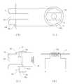
도 1a, 도 1b 및 도 1c는 본 발명에 따른 전자담배의 외부 공기 유입 구조가 적용될 수 있는 전자담배의 실시 예, 도 1a에 대한 부분 확대도 및 기화 유닛의 실시 예를 각각 도시한 것이다.
도 2a 및 도 2b는 본 발명에 따른 전원 연결의 위한 가압 스위치 구조 및 외부 공기 유입 구조의 실시 예를 도시한 것이다.1A, 1B and 1C show an embodiment of an electronic cigarette to which an external air inflow structure of the electronic cigarette according to the present invention can be applied, and a partial enlarged view and an embodiment of the vaporization unit of FIG. 1A, respectively.
2A and 2B illustrate an embodiment of a pressurized switch structure and an external air inlet structure for power connection according to the present invention.
아래에서 본 발명은 첨부된 도면에 제시된 실시 예를 참조하여 상세하게 설명이 되지만 실시 예는 본 발명의 명확한 이해를 위한 것으로 본 발명은 이에 제한되지 않는다.DETAILED DESCRIPTION OF THE PREFERRED EMBODIMENTS Hereinafter, the present invention will be described in detail with reference to the embodiments shown in the accompanying drawings, but the present invention is not limited thereto.
도 1a, 도 1b 및 도 1c는 본 발명에 따른 전자담배의 외부 공기 유입 구조가 적용될 수 있는 전자담배의 실시 예, 도 1a에 대한 부분 확대도 및 기화 유닛의 실시 예를 각각 도시한 것이다.1A, 1B and 1C show an embodiment of an electronic cigarette to which an external air inflow structure of the electronic cigarette according to the present invention can be applied, and a partial enlarged view and an embodiment of the vaporization unit of FIG. 1A, respectively.
본 발명에 따른 외부 공기 유입 구조(113, 115, 12, 127)는 전력을 공급하는 배터리 어셈블리(11), 니코틴 용액의 기화를 위한 가열체 및 니코틴 용액의 공급을 위한 저장 용기를 포함하는 전자담배(10)에 적용될 수 있지만 이에 제한되지 않고 전자적 방식으로 작동하는 임의의 전자담배 구조에 적용될 수 있다.
본 명세서에서 외부 공기 유입 구조는 외부 공기를 전자 담배로 유입시키기 위한 구조를 의미하며 배터리 어셈블리와 기화 유닛(14) 사이에 형성되어 외부 공기를 기화 유닛(14)이 내부로 유입시키기 위한 구조를 말한다. 구체적으로 외부 공기 유입 구조(113, 115, 12, 127)는 외부 공기를 유입시키는 연결 챔버(113), 연결 챔버(113)로 유입된 외부 공기를 유도하는 공기 유도로(115), 연결 챔버(113)와 결합되는 유도 챔버(12) 및 유도 챔버(12)의 기화 유닛(14)으로 유도하는 공기 유입로(127)를 포함한다.The external
In the present specification, the external air inlet structure refers to a structure for introducing external air into the electronic cigarette, and refers to a structure formed between the battery assembly and the
도 1a, 도 1b 및 도 1c는 본 발명에 따른 전자담배의 외부 공기 유입 구조가 적용될 수 있는 전자담배의 실시 예, 도 1a에 대한 부분 확대도 및 기화 유닛의 실시 예를 각각 도시한 것이다.1A, 1B and 1C show an embodiment of an electronic cigarette to which an external air inflow structure of the electronic cigarette according to the present invention can be applied, and a partial enlarged view and an embodiment of the vaporization unit of FIG. 1A, respectively.
전자담배에 적용되는 본 발명에 따른 외부 공기 유입 구조는 배터리 어셈블리에 형성되고 둘레 면에 연결 나사 면(116)이 형성된 연결 챔버(113); 연결 챔버(113)의 내부에 형성된 접촉 편(114); 접촉 편(114)의 내부에 형성된 공기 유도로(115); 연결 나사 면(116)에 결합되는 결합 나사 면(123)을 가진 유도 챔버(12); 유도 챔버(12)의 내부에 형성되고 접촉 편(114)에 한쪽 끝이 접촉하는 연결 편(124); 연결 편(124)의 내부에 형성된 공기 유입로(127); 연결 편(124)의 접촉하는 면에 형성된 유입 홈(G); 및 외부로부터 연결 챔버(113) 내부로 관통된 유입 홀을 포함한다.The external air inflow structure according to the present invention applied to the electronic cigarette includes a
도 1a, 도 1b 및 도 1c를 참조하면, 전자담배(10)의 니코틴 용액 기화 구조는 니코틴 용액이 수용되는 저장 하우징(13); 저장 하우징(13)의 내부에 고정되고 기화 챔버(143)를 가진 기화 유닛(14); 기화 챔버(143)의 내부에 설치되는 가열체(133); 가열체(133)에 니코틴 용액을 공급하기 위한 공급 수단; 및 기화 챔버(143)로부터 저장 하우징(13)의 외부로 연장되는 배출 튜브(144)를 포함하고, 상기에서 니코틴 용액은 저장 하우징(13)의 내부 및 기화 챔버(143)의 외부에 저장된 니코틴 용액은 공급 수단을 통하여 기화 챔버(143)의 내부로 유입될 수 있다.1A, 1B and 1C, the nicotine solution vaporization structure of the
전자담배(10)는 배터리 어셈블리(11), 기화 어셈블리 및 공급 어셈블리를 포함할 수 있고 기화 어셈블리는 가열체(133)를 포함할 수 있고 그리고 공급 어셈블리는 저장 하우징(13)을 포함할 수 있다.The
배터리 어셈블리(11)는 전기회로기판(111), 배터리(112) 및 외부로부터 공기를 유입시키면서 다른 어셈블리와 연결시키는 연결 챔버(113)를 포함할 수 있다. 전자회로기판(111)에 엘이디와 같은 발광 장치(L)가 설치될 수 있고 배터리 어셈블리(11)의 한쪽 끝에 커버(C)가 설치되어 발광 장치(L)의 빛이 외부로 방출될 수 있다. 발광 장치(L)는 흡연을 할 때 외부로 빛이 방출되어 흡연의 시각적 효과를 높이기 위한 것이므로 반드시 설치되어야 하는 것은 아니다. 전자회로기판(111)은 연결단자(T)를 통하여 배터리(112)에 연결될 수 있고 스위치(S)에 의하여 개폐가 제어될 수 있다. 스위치(S)의 개폐는 예를 들어 공기의 유입에 의하여 제어되거나 수동으로 제어될 수 있다. 스위치(S)의 개폐 방법은 이 분야에서 공지된 방법 또는 이 분야에서 통상의 지식을 가진 자에 의하여 적절하게 선택될 수 있고 본 발명은 이에 제한되지 않는다.The
배터리 어셈블리(11)의 한쪽 끝에 연결 챔버(113)가 형성될 수 있다. 연결 챔버(113)는 속이 빈 원통 형상이 될 수 있으며 둘레 면의 일부에 연결 나사 면(116)이 형성되고 내부에 접촉 편(114)이 형성될 수 있다. 접촉 편(114)은 원통 형상이 될 수 있으며 내부에 공기 유도로(115)가 형성되어 유입 홀(D)을 통하여 유입되는 공기가 유도 챔버(12)로 유입될 수 있도록 한다. 도 1a에 도시된 것처럼, 연결 챔버(113)의 둘레 면과 접촉 편(114) 사이에 빈 공간이 형성되고 유입 홀(D)은 외부의 공기가 연결 챔버(113)의 내부로 유입될 수 있도록 연결 챔버(113)의 둘레 면을 외부로부터 내부로 관통하도록 형성될 수 있고 다수 개가 될 수 있다. 도 1a에 도시된 것처럼, 가압 스위치(117)는 배터리 어셈블리(11)에 설치될 수 있지만 이에 제한되지 않고 임의의 위치에 설치될 수 있다. 가압 스위치(117)는 사람의 손으로 누르면 작동하는 구조를 가질 수 있지만 이에 제한되지 않고 예를 들어 터치(touch) 방식으로 작동하는 구조를 가질 수 있다. 가압 스위치(117)의 실시 예에 대하여 아래에서 다시 설명이 된다. 배터리 어셈블리(11)는 연결 챔버(113)에 형성된 연결 나사면(116)을 이용하여 유도 챔버(12)에 결합될 수 있다.The
유도 챔버(12)는 전체적으로 속이 빈 원통 형상을 가지면서 연결 챔버(113)에 대응되는 형상 및 구조를 가질 수 있다. 연결 챔버(12)는 앞쪽에 형성된 접촉 링(121)으로부터 실린더 형상으로 연장되고 연장 둘레면(122)의 일부에 연결 나사면(116)과 결합되는 결합 나사면(123)이 형성될 수 있다. 둘레면(122)에 접촉 링(121)으로부터 유도 챔버(12)의 길이 방향을 따라 적어도 결합 나사면(123)의 일부까지 연장된 다수 개의 유도 홈(D1)이 형성될 수 있다. 유도 홈(D1)은 연장 둘레면(121)의 내부면을 따라 접촉 링(121)으로부터 적절한 길이만큼 연장되어 외부 공기가 유입이 가능하도록 형성될 수 있고 폭 또는 연장 길이는 특별히 제한되지 않는다. 연결 챔버(113)와 유도 챔버(12)가 결합되면 외부의 공기는 유입 홀(D)을 통하여 유입되어 유도 홈(D1)을 따라서 흐르게 되어 연결 챔버(113) 및 유도 챔버(12)의 내부로 유입될 수 있다. 결합이 된 상태에서 연결 챔버(113)와 유도 챔버(12)는 서로 겹치게 된다. 유도 챔버(12)의 다른 한쪽 면에 접촉 편(114)과 접촉하는 연결 편(124)이 형성될 수 있다. 연결 편(124)은 접촉 편(114)에 대응되는 형상인 원통형이 될 수 있고 중앙 부분에 길이 방향으로 관통된 공기 유입로(127)가 형성될 수 있다. 다른 한편으로 연결 편(124)의 아래쪽 둘레 면에 예를 들어 세라믹 또는 고무와 같은 절연체로 만들어진 절연 링(126)이 설치될 수 있다. 절연 링(126)은 연결 편(124)과 유도 챔버(12)의 외부 면이 전기적으로 서로 절연이 되도록 한다. 전자담배에서 배터리(112)로부터 전자회로기판(111) 및 가열체(133)에 전력을 공급하기 위한 배선은 다양한 방식으로 이루어질 수 있다. 예를 들어 가열체(133)에 전력을 공급하기 위하여 연결 챔버(113)와 유도 챔버(12)의 둘레 면을 전도성 소재로 만들어 동일 또는 유사한 전도성 소재로 만들어진 접촉 편(114) 및 이에 접촉된 연결 편(124)과 전기적으로 절연시킬 수 있다. 그리고 배터리(112)의 한쪽 극을 연결 챔버(113) 또는 유도 챔버(12)에 연결하고 다른 극을 접촉 편(114)에 연결시킬 수 있다. 이후 가열체(133)의 양쪽 끝은 유도 챔버(12)의 둘레면 및 연결 편(124)에 연결될 수 있다. 그리고 전자회로기판(111)에 대한 전력 공급은 전선을 이용하여 이루어질 수 있다. 전자회로기판(111) 또는 가열체(133)에 대한 전력 공급 방법은 다양한 방법으로 이루어질 수 있고 제시된 실시 예에 제한되지 않는다.The
유입 홀(D)을 통하여 유입되어 유도 홈(D1)을 따라 흐르는 공기가 공기 유입로(127)의 내부로 유입될 수 있는 연결 편(124)의 구조가 도 1b의 (가) 및 (나)에 도시되어 있다.The structure of the connecting
도 1b의 (가) 및 (나)는 연결 편(124)의 길이 방향에 대한 단면도 및 평면도를 각각 도시한 것이다. 도 1b의 (가) 및 (나)를 참조하면, 연결 편(124)이 접촉 편(114)과 접촉하는 면에 유입 홈(G)이 형성될 수 있다. 유입 홈(G)은 연결 편(124)의 접촉면을 가로지르는 일정폭을 가진 홈 형상이 될 수 있고 공기 유입로(127)를 관통할 수 있다. 이와 같은 유입 홈(G)의 구조는 연결 챔버(113) 또는 유도 챔버(12)의 내부에 존재하는 공기가 유입 홈(G)을 따라 흘러 공기 유입로(127)의 내부로 유입될 수 있도록 한다.(A) and (b) of FIG. 1B show a cross-sectional view and a plan view, respectively, in the longitudinal direction of the connecting
공기 유입로(127)는 저장 하우징(13)의 내부로 연결된다.The
유도 챔버(12)와 대응되는 형상을 가지는 저장 하우징(13)은 유도 챔버(12)의 한쪽 면과 접촉하는 분리 판(131), 분리 판(131)으로부터 연장되면서 속인 빈 원통 형상을 가지는 지지체(132), 지지체(132)의 내부에 형성된 공기 도관(127a) 및 지지체(132)의 앞쪽에 배치되는 가열체(133)를 포함한다. 분리 판(131)은 유도 챔버(12)와 저장 하우징(13)을 물리적으로 분리시킨다. 분리 판(131)으로부터 연장되는 지지체(132)는 가열체(133)의 내부에 삽입되어 니코틴 용액을 가열체(133)로 공급하는 아래에서 설명하는 니코틴 용액의 공급 수단을 지지하기 위하여 설치될 수 있다. 또한 지지체(132)는 가열체(133)의 한쪽 단자에 연결될 수 있다. 도 1b의 (라)에 도시된 것처럼 가열체(133)의 한쪽 단자는 지지체(132)에 연결되고 다른 쪽 단자는 공기 도관(127a)에 연결될 수 있다. 그리고 지지체(132)와 공기 도관(127a) 사이에 절연 링(126a)이 삽입되어 지지체(132)와 공기 도관(127a)을 전기적으로 서로 분리시킬 수 있다. 공기 유입로(127)와 공기 도관(127a)은 일체로 될 수 있고 그리고 도 1b의 (라)에 도시된 것처럼, 2개의 절연 링(126, 126a)도 마찬가지로 일체로 만들어질 수 있다.The
공기 도관(127a)을 통하여 저장 하우징(13)으로 유입된 공기는 가열체(133)로 공급될 수 있고 가열체(133)는 저장 하우징(13)으로부터 공급되는 니코틴 용액을 공기와 함께 기화시키고 기화된 니코틴 용액은 저장 하우징(13)의 외부로 배출될 수 있다. 저장 하우징(13)에 저장된 니코틴 용액은 니코틴 용액 공급 수단을 통하여 가열체(133)에 전달될 수 있다. 니코틴 용액 공급 수단은 아래에서 설명하는 섬유 집합체(F)가 될 수 있지만 이에 제한되지 않고 가열체(133)의 구조에 따라 다양한 니코틴 용액 공급 수단이 사용될 수 있다. 도 1a 및 도 1b에 도시된 실시 예에서 저장 하우징(13)에 저장된 니코틴 용액은 니크롬선과 같은 가열체(133)의 내부를 관통하는 구조를 가지지만 본 발명은 이에 제한되지 않는다.Air introduced into the
저장 하우징(13)의 내부에 기화 유닛(14)이 결합될 수 있다.The
도 1c는 본 발명에 공기 유입 구조가 적용되는 전자담배의 기화 유닛의 실시 예를 도시한 것이다.Figure 1c shows an embodiment of the vaporization unit of the electronic cigarette to which the air inlet structure is applied to the present invention.
도 1c를 참조하면, 기화 유닛(14)은 분리 판(131)에 결합되는 고정 판(141), 고정 판(141)으로부터 연장된 기화 챔버(142), 니코틴 용액의 공급을 위한 공급 통로(143) 및 기화 챔버(142)의 한쪽 면에 결합된 배출 튜브(144)를 포함할 수 있다. 고정 판(141)은 분리 판(131)에 견고하게 결합되거나 또는 분리 가능하도록 결합될 수 있는 임의의 판 형상을 가질 수 있고 예를 들어 접착제에 의하여 분리 판(131)에 견고하게 고정될 수 있다. 기화 챔버(142)는 속이 빈 실린더 형상이 될 수 있으며 가열체(133)가 수용된다. 공급 통로(143)는 예를 들어 기화 챔버(142)의 둘레 면에 형성된 관통 홀의 형상을 가질 수 있다. 도 1c에 도시된 것처럼, 니코틴 용액이 섬유 집합체(F)에 의하여 가열체(133)로 공급되는 경우 공급 통로(143)는 섬유 집합체(F)가 통과할 수 있도록 둘레 면에 형성된 2개의 관통 홀이 될 수 있다. 저장 하우징(13)의 내부와 기화 유닛(14)의 외부에 저장된 니코틴 용액은 공급 통로(143)를 통하여 기화 유닛(14)의 내부에 배치되는 가열체(133)로 공급될 수 있다. 가열체(133)로 공급된 니코틴 용액은 공기 도관(127a)을 통하여 유입된 공기와 함께 기화되어 배출 튜브(144)를 통하여 기화 유닛(14) 및 저장 하우징(13)의 외부로 배출될 수 있다.Referring to FIG. 1C, the
배출 튜브(144)를 통하여 기화 유닛(14) 및 저장 하우징(13)의 외부로 배출되는 기화된 니코틴 용액은 도 1a에 도시된 것처럼, 흡입 피스(15)를 통하여 흡입될 수 있다. 흡입 피스(14)는 결합 부분(151) 및 배출 부분(152)으로 이루어질 수 있고 저장 하우징(13)에 분리 가능하도록 결합될 수 있다. 흡입 피스(14)의 결합 구조 또는 형상은 제한되지 않으면 이 분야에서 공지된 임의의 형태로 만들어질 수 있다.The vaporized nicotine solution exiting the
아래에서 본 발명에 따른 공기 유입 구조의 실시 예에 대하여 설명한다.Hereinafter, an embodiment of the air inflow structure according to the present invention will be described.
도 2a 및 도 2b는 본 발명에 따른 공기 유입 구조에 적용될 수 있는 가압 스위치 및 공기 유입구조의 실시 예를 도시한 것이다.2A and 2B illustrate an embodiment of a pressure switch and an air inlet structure that can be applied to an air inlet structure according to the present invention.
전자담배는 배터리에 공급되는 전력에 의하여 회로기판을 작동시키는 한편 가열체를 작동시켜 니코틴 용액이 기화되도록 하는 방식으로 작동된다. 그러므로 회로기판과 가열체의 전기적 연결을 제어하는 스위치가 필요하다. 스위치는 흡입되는 공기를 감지하여 작동하거나 또는 수동으로 작동할 수 있다. 수동 스위치는 예를 들어 외부에 노출된 스위치에 일정한 압력을 가하는 방식으로 작동되거나 또는 터치 방식으로 작동하는 것을 의미하고 아래에서 일정한 압력을 가하는 방식으로 작동하는 스위치에 대하여 설명된다.Electronic cigarettes are operated in such a way that the circuit board is operated by the power supplied to the battery while the heating body is operated to vaporize the nicotine solution. Therefore, a switch is needed to control the electrical connection between the circuit board and the heating element. The switch can be activated by sensing the air being sucked or manually. The manual switch is described, for example, by means of applying a constant pressure to a switch exposed to the outside or by operating in a touch manner, and hereinafter, a switch operating in a manner of applying a constant pressure.
도 2a의 (가)를 참조하면, 가압 스위치(117)는 외부로 노출되는 가압 판(21), 전극(26a, 26b)에 접촉하는 접촉 판(22), 가압 판(21)과 접촉 판(22)을 지지하는 고정 수단(27), 가압 판(21)의 상하 이동을 위한 이동 수단(23), 이동 수단(23)의 복원을 위한 탄성 수단(24) 및 이동 수단(23)의 수용을 위한 수용 박스(25)를 포함할 수 있다. 가압 판(21)은 배터리 어셈블리의 표면으로 노출될 수 있고 나머지 구성 요소들은 배터리 어셈블리의 내부에 위치할 수 있다. 가압 판(21)에 압력이 가해지면 이동 수단(23)의 이동에 의하여 접촉 판(22)이 아래쪽으로 이동하여 전극(26a, 26b)에 접촉하게 된다. 이후 가압 판(21)에 가해진 압력이 제거되면 탄성 수단(24)의 복원력에 의하여 가압 판(21)이 위쪽으로 이동하게 되면서 접촉 판(22)이 전극(26a, 26b)으로부터 분리된다.Referring to (a) of FIG. 2A, the
제시된 실시 예는 예시적인 것으로 가압 스위치(117)는 이 분야에서 공지된 다양한 방법으로 만들어질 수 있고 배터리 어셈블리의 적절한 위치에 설치될 수 있다. 필요에 따라 스위치는 터치 방식으로 만들어질 수 있다.The embodiment shown is exemplary and the
각각의 전극(26a, 26b)이 전자회로기판 또는 가열체에 연결되는 방법은 다양한 방식으로 이루어질 수 있다. 아래에서 각각의 전극(26a, 26b)을 가열체에 연결시키는 공기 유입 구조에 대하여 설명한다.The method in which each
도 2a의 (나)는 가열체에 각각의 전극(26a, 26b)을 연결시키는 공기 유입을 위한 구조의 실시 예를 도시한 것이다.Figure 2a (b) shows an embodiment of the structure for the air inlet connecting each electrode (26a, 26b) to the heating body.
도 2a의 (나)를 참조하면, 배터리 어셈블리에 포함되는 연결 챔버(113)의 내부에 형성된 접촉 편(114)과 기화 어셈블리에 형성된 연결 편(124)은 서로 접촉이 될 수 있다.Referring to (b) of FIG. 2A, the
접촉 편(114)의 내부에 공기 유도로(115)가 형성되고 공기 유도로(115)의 외부에 연결 나사면(116)이 형성된 둘레 면이 형성될 수 있다. 연결 챔버(113)가 시작되는 위치에 둘레 면의 외부에서 내부로 관통되는 유입 홀(D)이 형성될 수 있다. 다른 한편으로 연결 편(124)의 외부에 형성된 연장 둘레면(122)에 연결 나사면(116)에 결합되는 결합 나사면(123)이 형성되고 연장 둘레 면(122)의 끝 부분은 유입 홀(D)이 외부로 노출되도록 형성될 수 있다. 유입 홀(D)이 형성되도록 하는 방법은 예를 들어 연장 둘레 면(122)의 끝 부분에 일정 간격으로 노출 홈을 형성하여 연결 나사면(116)과 결합 나사면(123)이 완전히 결합된 경우 유입 홀(D)이 노출 홈을 통하여 외부로 노출되도록 만들어질 수 있다. 공기 유입로(127)는 공기 유도로(115)의 공기가 유입될 수 있는 구조로 형성될 수 있다. 한편 연결 편(124)의 아래쪽에 연결 편(124)과 연장 둘레면(122)을 절연시키기 위한 절연 링(126)이 삽입될 수 있다. 절연 링(126)에 의하여 연장 둘레면(122)과 연결 편(124)의 전기적 분리는 전극(26a, 26b)의 연결을 위하여 필요하다.An
아래에서 유입 홀(D)을 통하여 외부에서 유입된 공기가 공기 유입로(127)의 내부로 유입되는 구조에 대하여 설명한다.Hereinafter, a structure in which air introduced from the outside through the inflow hole D is introduced into the
도 2b는 외부 공기가 공기 유입로(127)의 내부로 유입될 수 있도록 하는 연결 챔버(113)와 연결 편(124)의 구조를 도시한 것이다.FIG. 2B illustrates the structure of the connecting
도 2b의 (나)를 참조하면, 연결 편(114)의 끝 부분에 공기 유입로(127)를 가로지르는 유입 홈(G)이 형성될 수 있다. 접촉 편(114)과 연결 편(124)의 끝 부분이 서로 접촉되면 유입 홀(D)을 통하여 외부로부터 유입된 공기는 유입 홈(G)을 통하여 공기 유입로(127)의 내부로 유입될 수 있다. 이와 같이 유입 홈(G)을 형성하는 것에 의하여 외부의 공기가 공기 유입로(127)의 내부로 유입되어 가열체로 공급될 수 있도록 하면서 이와 동시에 접촉 편(114)과 연결 편(124)의 접촉에 의하여 전기적으로 서로 연결이 될 수 있도록 한다. 그러므로 도 2a의 실시 예에서 제시된 하나의 전극(26a)은 연결 챔버(113)의 둘레 면에 연결되고 나머지 하나의 전극(26b)은 접촉 편(114)에 연결되도록 하는 것에 의하여 가열체에 전력이 공급될 수 있도록 한다.Referring to (b) of FIG. 2B, an inflow groove G that crosses the
도 2a 및 도 2b에 도시되지 않았지만 도 1a에서 설명한 것과 같은 유도 홈(D1)이 제시된 실시 예에 형성될 수 있다. 유도 홈(D1)은 유입 홀(D)을 통하여 유입되는 외부 공기가 유도 챔버(12)의 내부로 용이하게 흐를 수 있도록 한다. 연결 챔버(113)와 유도 챔버(12)가 결합되면 유도 홈(D1)과 유입 홀(D)이 일치하도록 연결 나사면(116) 및 결합 나사면(123)이 형성될 수 있다.Although not shown in FIGS. 2A and 2B, an induction groove D1 as described in FIG. 1A may be formed in the illustrated embodiment. The induction groove D1 allows the outside air introduced through the inflow hole D to easily flow into the
위에서 제시된 유입 홀(D) 또는 유입 홈(G)은 예시적인 것으로 유입 홀(D) 또는 유입 홈(G)은 다양한 위치에 다양한 방법으로 형성될 수 있고 본 발명은 이에 제한되지 않는다.The inlet holes D or the inlet grooves G provided above are exemplary and the inlet holes D or the inlet grooves G may be formed in various ways in various ways, and the present invention is not limited thereto.
본 발명에 따른 전자담배의 외부 공기 유입 구조는 가열체에 효과적으로 공기를 전달하여 니코틴 용액이 쉽게 기화할 수 있도록 한다는 이점을 가진다. 또한 본 발명에 따른 외부 공기 유입 구조는 공기 유입 통로가 가열체에 대한 전극 기능을 가지도록 하는 것에 의하여 전자담배 내부의 배선 구조가 간단해지도록 한다는 이점을 가진다. 추가로 본 발명에 따른 외부 공기 유입 구조는 정해진 공기 유입구를 통해서만 외부 공기가 유입되도록 하는 것에 의하여 기화된 니코틴 용액의 흡입이 원활하게 이루어지도록 한다는 장점을 가진다.The external air inlet structure of the electronic cigarette according to the present invention has an advantage that the nicotine solution can be easily vaporized by effectively delivering air to the heating body. In addition, the external air inlet structure according to the present invention has the advantage that the wiring structure inside the electronic cigarette is simplified by having the air inlet passage having an electrode function for the heating element. In addition, the external air inlet structure according to the present invention has an advantage of allowing the suction of the vaporized nicotine solution to be made smoothly by allowing external air to be introduced only through a predetermined air inlet.
위에서 본 발명의 제시된 실시 예를 참조하여 상세하게 설명이 되었지만 이 분야에서 통상의 지식을 가진 자는 제시된 실시 예를 참조하여 본 발명의 기술적 사상을 벗어나지 않는 범위에서 다양한 변형 및 수정 발명을 만들 수 있을 것이다. 본 발명은 이와 같은 변형 및 수정 발명에 의하여 제한되지 않으면 다만 아래에 첨부된 청구범위에 의하여 제한된다.Although described in detail above with reference to the embodiments of the present invention, those skilled in the art will be able to make various modifications and modifications to the invention without departing from the spirit of the present invention with reference to the embodiments presented. . The invention is not limited by these variations and modifications, but is only limited by the scope of the appended claims.
11: 배터리 어셈블리 12: 유도 챔버 13: 저장 하우징
14: 기화 유닛 15: 흡입 필터
111: 전자회로기판 112: 배터리 113: 연결 챔버
114: 접촉 편 115: 공기 유도로 116:연결 나사면
117: 가압 스위치 12: 유도 챔버
121: 접촉 링 122: 연장 둘레면 123: 결합 나사면
124: 연결 편 126: 절연 링 127: 공기 유입로
131: 분리 판 132: 지지체 127a: 공기 도관
133: 가열체 134: 공급 편 126, 126a: 절연 링
127: 공기 유입로
141: 고정 판 142: 기화 챔버 143: 공급 통로
144: 배출 튜브
15: 흡입 피스 151: 결합 부분 152: 흡입 부분
21: 가압 판 26a, 26b: 전극
22: 접촉 판 27: 고정 수단 23: 이송 수단
24: 탄성 수단 25: 수용 박스
C: 커버 L: 발광 장치 S: 스위치
D: 유입 홀 D1: 유도 홈 G: 유입 홈11: battery assembly 12: induction chamber 13: storage housing
14: vaporization unit 15: suction filter
111: electronic circuit board 112: battery 113: connection chamber
114: contact piece 115: air induction furnace 116: connecting screw surface
117: pressure switch 12: induction chamber
121: contact ring 122: extension peripheral surface 123: coupling screw surface
124: connecting piece 126: insulating ring 127: air inlet
131: separation plate 132:
133: heating element 134:
127: air inlet
141: fixing plate 142: vaporization chamber 143: supply passage
144: discharge tube
15: suction piece 151: coupling portion 152: suction portion
21:
22: contact plate 27: fixing means 23: conveying means
24: elastic means 25: housing box
C: cover L: light emitting device S: switch
D: Inflow hole D1: Induction groove G: Inflow groove
Claims (5)
Translated fromKorean배터리 어셈블리에 형성되고 둘레 면에 연결 나사 면(116)이 형성된 연결 챔버(113);
연결 챔버(113)의 내부에 형성된 접촉 편(114);
접촉 편(114)의 내부에 형성된 공기 유도로(115);
연결 나사 면(116)에 결합되는 결합 나사 면(123)을 가진 유도 챔버(12);
유도 챔버(12)의 내부에 형성되고 접촉 편(114)에 한쪽 끝이 접촉하는 연결 편(124);
연결 편(124)의 내부에 형성된 공기 유입로(127);
연결 편(124)의 접촉하는 면에 형성된 유입 홈(G); 및
외부로부터 연결 챔버(113) 내부로 관통된 유입 홀(D)을 포함하는 전자담배를 위한 외부 공기 유입 구조.In the external air inlet structure (113, 115, 12, 127) for an electronic cigarette comprising a battery assembly for supplying power, a heating body for vaporizing the nicotine solution and a storage housing for supplying the nicotine solution,
A connection chamber 113 formed in the battery assembly and having a connection screw surface 116 formed on a circumferential surface thereof;
A contact piece 114 formed in the connection chamber 113;
An air induction path 115 formed inside the contact piece 114;
An induction chamber 12 having a mating screw face 123 coupled to a connecting screw face 116;
A connection piece 124 formed inside the induction chamber 12 and having one end contacting the contact piece 114;
An air inflow path 127 formed in the connection piece 124;
An inflow groove G formed in a contact surface of the connection piece 124; And
External air inlet structure for an electronic cigarette comprising an inlet hole (D) penetrated into the connection chamber 113 from the outside.
The outside air inlet structure of claim 4, wherein the induction chamber (12) and the connecting piece (124) are electrically separated by an insulating ring (126).
Priority Applications (1)
| Application Number | Priority Date | Filing Date | Title |
|---|---|---|---|
| KR1020110001642AKR101241782B1 (en) | 2011-01-07 | 2011-01-07 | Structure for Supplying Outer Air in Electric Cigarette |
Applications Claiming Priority (1)
| Application Number | Priority Date | Filing Date | Title |
|---|---|---|---|
| KR1020110001642AKR101241782B1 (en) | 2011-01-07 | 2011-01-07 | Structure for Supplying Outer Air in Electric Cigarette |
Publications (2)
| Publication Number | Publication Date |
|---|---|
| KR20120080287A KR20120080287A (en) | 2012-07-17 |
| KR101241782B1true KR101241782B1 (en) | 2013-03-14 |
Family
ID=46712926
Family Applications (1)
| Application Number | Title | Priority Date | Filing Date |
|---|---|---|---|
| KR1020110001642AExpired - Fee RelatedKR101241782B1 (en) | 2011-01-07 | 2011-01-07 | Structure for Supplying Outer Air in Electric Cigarette |
Country Status (1)
| Country | Link |
|---|---|
| KR (1) | KR101241782B1 (en) |
Cited By (5)
| Publication number | Priority date | Publication date | Assignee | Title |
|---|---|---|---|---|
| WO2014153719A1 (en)* | 2013-03-26 | 2014-10-02 | Liu Qiuming | Electronic cigarette |
| KR200475494Y1 (en)* | 2013-07-02 | 2014-12-05 | 조득상 | Connector for an electronic cigarette |
| US11641871B2 (en) | 2006-10-18 | 2023-05-09 | Rai Strategic Holdings, Inc. | Tobacco-containing smoking article |
| US11659868B2 (en) | 2014-02-28 | 2023-05-30 | Rai Strategic Holdings, Inc. | Control body for an electronic smoking article |
| US11779051B2 (en) | 2011-08-09 | 2023-10-10 | Rai Strategic Holdings, Inc. | Smoking articles and use thereof for yielding inhalation materials |
Families Citing this family (9)
| Publication number | Priority date | Publication date | Assignee | Title |
|---|---|---|---|---|
| WO2015010277A1 (en)* | 2013-07-24 | 2015-01-29 | 吉瑞高新科技股份有限公司 | Electronic cigarette |
| WO2015013891A1 (en)* | 2013-07-30 | 2015-02-05 | 吉瑞高新科技股份有限公司 | Electronic cigarette |
| WO2015017971A1 (en)* | 2013-08-06 | 2015-02-12 | 吉瑞高新科技股份有限公司 | Electronic cigarette |
| SG11201601985VA (en) | 2013-10-29 | 2016-04-28 | British American Tobacco Co | Apparatus for heating smokable material |
| KR101663431B1 (en)* | 2015-06-12 | 2016-10-07 | 조인진 | Electronic cigarette |
| GB2559535A (en)* | 2015-09-22 | 2018-08-15 | Nicoventures Holdings Ltd | Aerosol provision system with remote air inlet |
| KR102783174B1 (en)* | 2016-02-12 | 2025-03-19 | 필립모리스 프로덕츠 에스.에이. | Aerosol generating system with electrodes |
| KR102339232B1 (en)* | 2017-04-13 | 2021-12-13 | 차이나 토바코 후난 인더스트리얼 코포레이션 리미티드 | Atomizer and its electronic cigarette |
| EP3795007A1 (en)* | 2019-09-20 | 2021-03-24 | Nerudia Limited | Smoking substitute apparatus |
Citations (2)
| Publication number | Priority date | Publication date | Assignee | Title |
|---|---|---|---|---|
| KR100918785B1 (en) | 2008-06-26 | 2009-09-23 | 주식회사 에바코 | Nonflammable electronic cigarette |
| KR20090121957A (en)* | 2008-05-23 | 2009-11-26 | 조여찬 | Electronic cigarette |
- 2011
- 2011-01-07KRKR1020110001642Apatent/KR101241782B1/ennot_activeExpired - Fee Related
Patent Citations (2)
| Publication number | Priority date | Publication date | Assignee | Title |
|---|---|---|---|---|
| KR20090121957A (en)* | 2008-05-23 | 2009-11-26 | 조여찬 | Electronic cigarette |
| KR100918785B1 (en) | 2008-06-26 | 2009-09-23 | 주식회사 에바코 | Nonflammable electronic cigarette |
Cited By (13)
| Publication number | Priority date | Publication date | Assignee | Title |
|---|---|---|---|---|
| US11805806B2 (en) | 2006-10-18 | 2023-11-07 | Rai Strategic Holdings, Inc. | Tobacco-containing smoking article |
| US11986009B2 (en) | 2006-10-18 | 2024-05-21 | Rai Strategic Holdings, Inc. | Tobacco-containing smoking article |
| US11641871B2 (en) | 2006-10-18 | 2023-05-09 | Rai Strategic Holdings, Inc. | Tobacco-containing smoking article |
| US11647781B2 (en) | 2006-10-18 | 2023-05-16 | Rai Strategic Holdings, Inc. | Tobacco-containing smoking article |
| US11980220B2 (en) | 2006-10-18 | 2024-05-14 | Rai Strategic Holdings, Inc. | Tobacco-containing smoking article |
| US11758936B2 (en) | 2006-10-18 | 2023-09-19 | Rai Strategic Holdings, Inc. | Tobacco-containing smoking article |
| US11925202B2 (en) | 2006-10-18 | 2024-03-12 | Rai Strategic Holdings, Inc. | Tobacco-containing smoking article |
| US11785978B2 (en) | 2006-10-18 | 2023-10-17 | Rai Strategic Holdings, Inc. | Tobacco-containing smoking article |
| US11779051B2 (en) | 2011-08-09 | 2023-10-10 | Rai Strategic Holdings, Inc. | Smoking articles and use thereof for yielding inhalation materials |
| WO2014153719A1 (en)* | 2013-03-26 | 2014-10-02 | Liu Qiuming | Electronic cigarette |
| KR200475494Y1 (en)* | 2013-07-02 | 2014-12-05 | 조득상 | Connector for an electronic cigarette |
| US11864584B2 (en) | 2014-02-28 | 2024-01-09 | Rai Strategic Holdings, Inc. | Control body for an electronic smoking article |
| US11659868B2 (en) | 2014-02-28 | 2023-05-30 | Rai Strategic Holdings, Inc. | Control body for an electronic smoking article |
Also Published As
| Publication number | Publication date |
|---|---|
| KR20120080287A (en) | 2012-07-17 |
Similar Documents
| Publication | Publication Date | Title |
|---|---|---|
| KR101241782B1 (en) | Structure for Supplying Outer Air in Electric Cigarette | |
| KR101241779B1 (en) | Structure for Evaporating Nicotine Solution in Electric Cigarette | |
| US12168094B2 (en) | High frequency polarization aerosol generator | |
| KR101265170B1 (en) | Container of Nicotine Solution for Electric Cigarette and Electric Cigarette with the Same | |
| RU2665613C1 (en) | Electronic device for generation of aerosol and method of generation of aerosol | |
| US11375752B1 (en) | Portable electronic vaporizer having removably attachable vaporization module and device, removably attachable base portion, and method | |
| KR101486294B1 (en) | A electronic cigarette | |
| KR101516304B1 (en) | Electrical Cigarette | |
| KR200470732Y1 (en) | Vaporizing and inhaling apparatus and vaporizing member applied the vaporizing and inhaling apparatus | |
| KR20210054072A (en) | Aerosol provision system | |
| CN107771038A (en) | electrical smoking device | |
| KR20190123553A (en) | heater assembly for cigarette type electronic device and cigarette type electronic device including the same | |
| KR101245581B1 (en) | Structure for Evaporating Nicotine Solution in Electric Cigarette | |
| KR101623429B1 (en) | Cartridge for Inhaling Apparatus with Electrical Power | |
| US11246339B2 (en) | Cantilevered operating button for an electronic vapor provision system | |
| KR20130031550A (en) | Cartridge with separated volume for electric cigarette | |
| KR101364772B1 (en) | Cartridge for Electronic Cigarette | |
| KR101245578B1 (en) | Structure for Supplying Nicotine Solution in Electric Cigarette | |
| US12096798B2 (en) | Portable electronic vaporizer having removably attachable vaporization module, removably attachable base portion, and method | |
| KR20160130342A (en) | Atomizing device for an electronic Cigarette | |
| KR101241785B1 (en) | Structure For Vaporizing Nicotine Solution in Electronic Cigarette | |
| KR20160080460A (en) | Structure for Evaporating Nicotine Solution in Electric Cigarette | |
| KR20160082567A (en) | Container of Nicotine Solution for Electric Cigarette and Electric Cigarette with the Same | |
| KR20160080568A (en) | Structure for Supplying Outer Air in Electric Cigarette | |
| KR101522699B1 (en) | A electronic cigarette |
Legal Events
| Date | Code | Title | Description |
|---|---|---|---|
| A201 | Request for examination | ||
| PA0109 | Patent application | St.27 status event code:A-0-1-A10-A12-nap-PA0109 | |
| PA0201 | Request for examination | St.27 status event code:A-1-2-D10-D11-exm-PA0201 | |
| P11-X000 | Amendment of application requested | St.27 status event code:A-2-2-P10-P11-nap-X000 | |
| PE0801 | Dismissal of amendment | St.27 status event code:A-2-2-P10-P12-nap-PE0801 | |
| D13-X000 | Search requested | St.27 status event code:A-1-2-D10-D13-srh-X000 | |
| D14-X000 | Search report completed | St.27 status event code:A-1-2-D10-D14-srh-X000 | |
| PG1501 | Laying open of application | St.27 status event code:A-1-1-Q10-Q12-nap-PG1501 | |
| E902 | Notification of reason for refusal | ||
| PE0902 | Notice of grounds for rejection | St.27 status event code:A-1-2-D10-D21-exm-PE0902 | |
| R17-X000 | Change to representative recorded | St.27 status event code:A-3-3-R10-R17-oth-X000 | |
| P11-X000 | Amendment of application requested | St.27 status event code:A-2-2-P10-P11-nap-X000 | |
| P13-X000 | Application amended | St.27 status event code:A-2-2-P10-P13-nap-X000 | |
| E701 | Decision to grant or registration of patent right | ||
| PE0701 | Decision of registration | St.27 status event code:A-1-2-D10-D22-exm-PE0701 | |
| GRNT | Written decision to grant | ||
| PR0701 | Registration of establishment | St.27 status event code:A-2-4-F10-F11-exm-PR0701 | |
| PR1002 | Payment of registration fee | St.27 status event code:A-2-2-U10-U11-oth-PR1002 Fee payment year number:1 | |
| PG1601 | Publication of registration | St.27 status event code:A-4-4-Q10-Q13-nap-PG1601 | |
| PN2301 | Change of applicant | St.27 status event code:A-5-5-R10-R13-asn-PN2301 St.27 status event code:A-5-5-R10-R11-asn-PN2301 | |
| A110 | Patent application of lawful right holder | ||
| PA0110 | Patent application of the lawful right holder | St.27 status event code:A-0-1-A10-A12-nap-PA0110 | |
| LAPS | Lapse due to unpaid annual fee | ||
| PC1903 | Unpaid annual fee | St.27 status event code:A-4-4-U10-U13-oth-PC1903 Not in force date:20160306 Payment event data comment text:Termination Category : DEFAULT_OF_REGISTRATION_FEE | |
| P22-X000 | Classification modified | St.27 status event code:A-4-4-P10-P22-nap-X000 | |
| PC1903 | Unpaid annual fee | St.27 status event code:N-4-6-H10-H13-oth-PC1903 Ip right cessation event data comment text:Termination Category : DEFAULT_OF_REGISTRATION_FEE Not in force date:20160306 | |
| P22-X000 | Classification modified | St.27 status event code:A-4-4-P10-P22-nap-X000 | |
| P22-X000 | Classification modified | St.27 status event code:A-4-4-P10-P22-nap-X000 |