KR101241495B1 - A wireless power transmission apparatus and method thereof - Google Patents
A wireless power transmission apparatus and method thereofDownload PDFInfo
- Publication number
- KR101241495B1 KR101241495B1KR1020110055291AKR20110055291AKR101241495B1KR 101241495 B1KR101241495 B1KR 101241495B1KR 1020110055291 AKR1020110055291 AKR 1020110055291AKR 20110055291 AKR20110055291 AKR 20110055291AKR 101241495 B1KR101241495 B1KR 101241495B1
- Authority
- KR
- South Korea
- Prior art keywords
- power
- magnetic field
- coil
- transmission
- detector
- Prior art date
- Legal status (The legal status is an assumption and is not a legal conclusion. Google has not performed a legal analysis and makes no representation as to the accuracy of the status listed.)
- Expired - Fee Related
Links
Images


Classifications
- H—ELECTRICITY
- H02—GENERATION; CONVERSION OR DISTRIBUTION OF ELECTRIC POWER
- H02J—CIRCUIT ARRANGEMENTS OR SYSTEMS FOR SUPPLYING OR DISTRIBUTING ELECTRIC POWER; SYSTEMS FOR STORING ELECTRIC ENERGY
- H02J50/00—Circuit arrangements or systems for wireless supply or distribution of electric power
- H02J50/80—Circuit arrangements or systems for wireless supply or distribution of electric power involving the exchange of data, concerning supply or distribution of electric power, between transmitting devices and receiving devices
- H—ELECTRICITY
- H01—ELECTRIC ELEMENTS
- H01F—MAGNETS; INDUCTANCES; TRANSFORMERS; SELECTION OF MATERIALS FOR THEIR MAGNETIC PROPERTIES
- H01F38/00—Adaptations of transformers or inductances for specific applications or functions
- H01F38/14—Inductive couplings
- H—ELECTRICITY
- H02—GENERATION; CONVERSION OR DISTRIBUTION OF ELECTRIC POWER
- H02J—CIRCUIT ARRANGEMENTS OR SYSTEMS FOR SUPPLYING OR DISTRIBUTING ELECTRIC POWER; SYSTEMS FOR STORING ELECTRIC ENERGY
- H02J50/00—Circuit arrangements or systems for wireless supply or distribution of electric power
- H02J50/005—Mechanical details of housing or structure aiming to accommodate the power transfer means, e.g. mechanical integration of coils, antennas or transducers into emitting or receiving devices
- H—ELECTRICITY
- H02—GENERATION; CONVERSION OR DISTRIBUTION OF ELECTRIC POWER
- H02J—CIRCUIT ARRANGEMENTS OR SYSTEMS FOR SUPPLYING OR DISTRIBUTING ELECTRIC POWER; SYSTEMS FOR STORING ELECTRIC ENERGY
- H02J50/00—Circuit arrangements or systems for wireless supply or distribution of electric power
- H02J50/10—Circuit arrangements or systems for wireless supply or distribution of electric power using inductive coupling
- H02J50/12—Circuit arrangements or systems for wireless supply or distribution of electric power using inductive coupling of the resonant type
- H—ELECTRICITY
- H02—GENERATION; CONVERSION OR DISTRIBUTION OF ELECTRIC POWER
- H02J—CIRCUIT ARRANGEMENTS OR SYSTEMS FOR SUPPLYING OR DISTRIBUTING ELECTRIC POWER; SYSTEMS FOR STORING ELECTRIC ENERGY
- H02J50/00—Circuit arrangements or systems for wireless supply or distribution of electric power
- H02J50/50—Circuit arrangements or systems for wireless supply or distribution of electric power using additional energy repeaters between transmitting devices and receiving devices
- H02J50/502—Circuit arrangements or systems for wireless supply or distribution of electric power using additional energy repeaters between transmitting devices and receiving devices the energy repeater being integrated together with the emitter or the receiver
- H—ELECTRICITY
- H02—GENERATION; CONVERSION OR DISTRIBUTION OF ELECTRIC POWER
- H02J—CIRCUIT ARRANGEMENTS OR SYSTEMS FOR SUPPLYING OR DISTRIBUTING ELECTRIC POWER; SYSTEMS FOR STORING ELECTRIC ENERGY
- H02J50/00—Circuit arrangements or systems for wireless supply or distribution of electric power
- H02J50/90—Circuit arrangements or systems for wireless supply or distribution of electric power involving detection or optimisation of position, e.g. alignment
- H—ELECTRICITY
- H04—ELECTRIC COMMUNICATION TECHNIQUE
- H04B—TRANSMISSION
- H04B5/00—Near-field transmission systems, e.g. inductive or capacitive transmission systems
- H04B5/70—Near-field transmission systems, e.g. inductive or capacitive transmission systems specially adapted for specific purposes
- H04B5/79—Near-field transmission systems, e.g. inductive or capacitive transmission systems specially adapted for specific purposes for data transfer in combination with power transfer
Landscapes
- Engineering & Computer Science (AREA)
- Power Engineering (AREA)
- Computer Networks & Wireless Communication (AREA)
- Signal Processing (AREA)
- Charge And Discharge Circuits For Batteries Or The Like (AREA)
- Near-Field Transmission Systems (AREA)
Abstract
Translated fromKoreanDescription
Translated fromKorean본 발명은 무선 전력 전송 기술에 관한 것이다. 보다 구체적으로, 본 발명은 소위 자기 공진 현상을 이용한 무선 전력 전송에 있어서, 무선 전력 송신 장치 측의 송신용 공진 코일에 저장되는 에너지를 검출할 수 있는 검출용 코일을 장착하여 수신장치가 멀리 떨어져 있는지를 검출한다. 수신장치가 멀리 떨어져 있거나 존재하지 않는 것으로 판단되는 경우 송신되는 전력의 세기를 감소시켜 전력 손실을 방지할 수 있다.The present invention relates to wireless power transfer technology. More specifically, in the wireless power transmission using a so-called self-resonant phenomenon, the present invention is equipped with a detection coil capable of detecting energy stored in the transmission resonant coil on the wireless power transmission device side to see if the receiving device is far away. Detect. When it is determined that the receiving device is far away or does not exist, power loss can be prevented by reducing the strength of transmitted power.
무선으로 전기 에너지를 원하는 기기로 전달하는 무선전력전송 기술(wireless power transmission 또는 wireless energy transfer)은 이미 1800년대에 전자기유도 원리를 이용한 전기 모터나 변압기가 사용되기 시작했고, 그 후로는 라디오파나 레이저와 같은 전자파를 방사해서 전기에너지를 전송하는 방법도 시도되었다. 우리가 흔히 사용하는 전동칫솔이나 일부 무선면도기도 실상은 전자기유도 원리로 충전된다. 현재까지 무선 방식에 의한 에너지 전달 방식은 자기 유도, 자기 공진 및 단파장 무선 주파수를 이용한 원거리 송신 기술 등이 있다.In the 1800s, electric motors and transformers using electromagnetic induction principles began to be used, and then radio waves and lasers were used to transmit the electric energy to the desired devices wirelessly. A method of transmitting electrical energy by radiating the same electromagnetic wave has also been attempted. Our electric toothbrushes and some wireless shavers are actually charged with electromagnetic induction. To date, energy transmission methods using wireless methods include magnetic induction, magnetic resonance, and long-distance transmission technology using short wavelength radio frequencies.
최근에 이슈가 되고 있는 단거리 무선 전력 전송 기술의 응용 분야를 보면, 건물 내에 무선 전력 송신기를 설치하고, 건물 내부에서 사용자가 휴대폰이나 노트북 등의 모바일 기기를 사용하면 별도의 전원 케이블을 연결하지 않아도 계속해서 충전이 수행되는 경우가 대표적이다.In recent years, the application of short-range wireless power transmission technology has been installed. If a wireless power transmitter is installed in a building and a user uses a mobile device such as a mobile phone or a laptop in the building, there is no need to connect a separate power cable. This is typical when charging is performed.
그런데, 종래의 무선 전력 전송 기술에서는 전력을 수신하는 수신기 존재 여부와 관계없이 항상 일정 전력을 송신하여야 하므로 전력이 낭비되는 문제점이 있다.However, in the conventional wireless power transmission technology, there is a problem in that power is wasted because constant power must always be transmitted regardless of whether there is a receiver for receiving power.
본 발명은 무선 전력 전송에 있어서, 수신기의 존재 여부 또는 근접 여부에 따라 송신 전력을 조절함으로써 전력 낭비를 방지할 수 있는 방법을 제공하는 것을 목적으로 한다.SUMMARY OF THE INVENTION An object of the present invention is to provide a method of preventing waste of power by adjusting transmission power according to whether a receiver is present or close in wireless power transmission.
본 발명의 일 실시예에 따른 무선 전력 송신 장치는 전력소스로부터 전력을 공급받아 자기장을 발생하는 송신 코일부와, 상기 송신 코일부에서 발생한 자기장을 수신 코일로 송신하는 송신용 공진 코일부와, 상기 송신용 공진 코일부를 통해 송신되는 자기장에 의하여 유도기전력을 발생하는 수신 코일의 근접 여부를 검출하는 검출부와, 상기 검출부를 통해 검출된 수신 코일의 근접 여부에 따라 상기 전력을 공급하는 전력 소스의 출력을 조절하는 전력 조절부를 포함한다..In accordance with an aspect of the present invention, there is provided a wireless power transmitter, comprising: a transmitting coil unit generating a magnetic field by receiving power from a power source; a transmitting coil unit transmitting a magnetic field generated by the transmitting coil unit to a receiving coil; A detector for detecting proximity of a receiving coil generating induction electromotive force by a magnetic field transmitted through a transmission resonant coil unit, and an output of a power source for supplying the electric power according to the proximity of the receiving coil detected through the detection unit It includes a power control unit for adjusting.
또한, 본 발명의 일 실시예에 따른 무선 전력 송신 방법은 전력 소스로부터 공급되는 전력에 의해 발생한 자기장을 송신하는 단계와, 상기 송신되는 자기장의 상태를 확인하는 단계와, 상기 확인된 자기장의 상태에 의거하여 상기 자기장을 수신하는 수신 코일의 근접 여부를 검출하는 단계와, 상기 검출된 수신 코일의 근접 여부에 의거하여 송신 전력을 조절하는 단계를 포함한다.In addition, the wireless power transmission method according to an embodiment of the present invention comprises the steps of transmitting a magnetic field generated by the power supplied from a power source, checking the state of the transmitted magnetic field, and the state of the identified magnetic field Detecting whether a receiving coil receiving the magnetic field is in proximity, and adjusting a transmission power based on whether the receiving coil is in proximity.
본 발명은 무선 전력 전송에 있어서, 수신기의 존재 여부 또는 근접 여부에 따라 송신 전력을 조절함으로써 전력 낭비를 방지할 수 있다.According to the present invention, in the wireless power transmission, power waste can be prevented by adjusting the transmission power according to the presence or proximity of the receiver.
도 1은 본 발명의 일 실시예에 따른 무선 전력 전송 시스템을 나타낸다.
도 2는 본 발명의 일 실시예에 따른, 송신 코일(21)의 등가 회로도이다.
도 3은 본 발명의 일 실시예에 따른, 전력 소스(10)와 송신부(20)의 등가회로이다.
도 4는 본 발명의 일 실시예에 따른, 수신용 공진 코일(31), 수신 코일(32), 평활 회로(40) 및 부하(50)의 등가회로를 나타낸다.
도 5는 본 발명의 일 실시예에 따른 무선 전력 송신기의 구성을 나타낸다.1 shows a wireless power transmission system according to an embodiment of the present invention.
2 is an equivalent circuit diagram of the
Figure 3 is an equivalent circuit of a
4 shows an equivalent circuit of the receiving
5 shows a configuration of a wireless power transmitter according to an embodiment of the present invention.
이하 도면을 참조하여 본 발명의 실시예들을 보다 상세히 설명한다.Embodiments of the present invention will now be described in more detail with reference to the drawings.
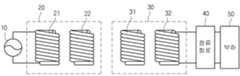
도 1은 본 발명의 일 실시예에 따른 무선 전력 전송 시스템을 나타낸다.1 shows a wireless power transmission system according to an embodiment of the present invention.
전력 소스(10)에서 생성된 전력은 송신장치(20)로 전달되고, 자기 공진 현상에 의해 송신장치(20)와 공진을 이루는 즉, 공진 주파수 값이 동일한 수신장치(30)로 전달된다. 수신장치(30)로 전달된 전력은 정류회로(40)를 거쳐 부하(50)로 전달된다. 부하(50)는 충전지 또는 기타 전력을 필요로 하는 임의의 장치일 수 있다.The power generated by the
보다 구체적으로 살펴보면, 전력 소스(10)는 소정 주파수의 교류 전력을 제공하는 교류 전력 소스이다.More specifically, the
송신장치(20)는 송신 코일(21)과 송신용 공진 코일(22)로 구성된다. 송신 코일(21)은 전력 소스(10)와 연결되며, 교류 전류가 흐르게 된다. 송신 코일(21)에 교류 전류가 흐르면, 전자기 유도에 의해 물리적으로 이격되어 있는 송신용 공진 코일(22)에도 교류 전류가 유도된다. 송신용 공진 코일(22)로 전달된 전력은 자기 공진에 의해 송신장치(20)와 공진 회로를 이루는 수신장치(30)로 전달된다.The transmitting
자기 공진에 의한 전력 전송은 임피던스가 매칭된 2개의 LC 회로간에 전력이 전송되는 현상으로써, 전자기 유도에 의한 전력 전송보다 먼 거리까지 높은 효율로 전력을 전달할 수 있다.Power transmission by magnetic resonance is a phenomenon in which power is transmitted between two LC circuits of which impedance is matched, and thus power can be transmitted with greater efficiency up to a far distance than power transmission by electromagnetic induction.
수신장치(30)는 수신용 공진 코일(31)과 수신 코일(32)로 구성된다. 송신용 공진 코일(22)에 의해 송신된 전력은 수신용 공진 코일(31)에 의해 수신되어 수신용 공진 코일(31)에 교류 전류가 흐르게 된다. 수신용 공진 코일(31)로 전달된 전력은 전자기 유도에 의해 수신 코일(32)로 전달된다. 수신코일(32)로 전달된 전력은 정류 회로(40)를 통해 정류되어 부하(50)로 전달된다.The
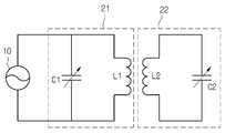
도 2는 본 발명의 일 실시예에 따른, 송신 코일(21)의 등가 회로도이다. 도 2에 도시된 바와 같이 송신 코일(21)은 인덕터(L1)와 캐패시터(C1)로 구성될 수 있으며, 이들에 의해 적절한 인덕턴스와 캐패시턴스 값을 갖는 회로를 구성하게 된다. 캐패시터(C1)는 가변 캐패시터일 수 있으며, 가변 캐패시터를 조절하여 임피던스 매칭을 수행할 수 있다. 송신용 공진 코일(22), 수신용 공진 코일(31), 수신 코일(32)의 등가 회로도 도 2에 도시된 것과 동일할 수 있다.2 is an equivalent circuit diagram of the
도 3은 본 발명의 일 실시예에 따른, 전력 소스(10)와 송신장치(20)의 등가회로이다. 도 3에 도시된 바와 같이, 송신 코일(21)과 송신용 공진 코일(22)은 각각 소정 인덕턴스 값과 캐패시턴스 값을 갖는 인덕터(L1,L2)와 캐패시터(C1,C2)로 구성될 수 있다.3 is an equivalent circuit of a
도 4는 본 발명의 일 실시예에 따른, 수신용 공진 코일(31), 수신 코일(32), 평활 회로(40) 및 부하(50)의 등가회로를 나타낸다.4 shows an equivalent circuit of the receiving
도 4에 도시된 바와 같이 수신용 공진 코일(31)과 수신 코일(32)은 각각 소정 인덕턴스 값과 캐패시턴스 값을 갖는 인덕터(L3,L4)와 캐패시터(C3,C4)로 구성될 수 있다. 평활 회로(40)는 다이오드(D1)와 평활 캐패시터(C5)로 구성될 수 있으며, 교류 전력을 직류 전력을 변환하여 출력한다. 부하(50)는 1.3V의 직류 전원으로 표시되어 있으나, 직류 전력을 필요로 하는 임의의 충전지 또는 장치일 수 있다.4, the receiving
한편, 본 발명의 일 실시예에 따라, 무선 전력 송신부 측에 수신기의 근접 여부를 검출하는 검출부를 장착하여 수신기의 근접 여부에 따라 송신 전력의 강도를 조절할 수 있다.Meanwhile, according to an embodiment of the present invention, the wireless power transmitter may be equipped with a detector that detects the proximity of the receiver, and adjust the strength of the transmission power according to the proximity of the receiver.
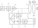
도 5는 본 발명의 일 실시예에 따른 무선 전력 송신기의 구성을 나타낸다.5 shows a configuration of a wireless power transmitter according to an embodiment of the present invention.
도 5에서 송신 코일(21) 및 송신 공진 코일(22)을 제외한 나머지 구성요소들은 도 1의 전력 소스(10)에 포함될 수 있다.In FIG. 5, the remaining components except for the
도 5에 도시된 바와 같이, 본 발명의 일 실시예에 따른 무선 전력 송신장치는 신호 발생부(11), 상기 신호 발생기(11)와 연결되어 자기장을 형성하는 송신 코일부(21), 상기 송신 코일부(21)와 커플링되어 전력을 송신하는 송신용 공진 코일부(22), 수신측 코일의 근접 여부를 검출하는 검출부(19), 및 상기 수신측 코일의 근접 여부에 따라, 상기 전력 소스의 출력을 조절하는 전력 조절부(12)를 포함할 수 있다.As shown in FIG. 5, a wireless power transmitter according to an embodiment of the present invention includes a
또한, 본 발명의 일 실시예에 따른 무선 전력 송신장치는, 상기 신호 발생부(11)의 출력을 증폭하여 상기 송신 코일부(21)로 전달하는 증폭부(13)를 더 포함할 수 있다.In addition, the wireless power transmitter according to an embodiment of the present invention may further include an
상기 검출부(19)는, 상기 신호 발생부(11)의 출력을 검출하여 직류로 변환하는 제1 파워 검출기(14), 상기 송신용 공진 코일부(22)에서 송신되는 자기장의 세기를 검출하는 검출용 코일(15), 상기 검출용 코일(15)에서 검출한 자기장에 의해 발생하는 전력을 직류로 변환하는 제2 파워 검출기(16), 및 상기 제1 파워 검출기(14)의 출력과 상기 제2 파워 검출기(16)의 출력을 비교하여 비교 결과를 상기 전력 조절부(12)로 전달하는 비교기를 포함할 수 있다.The
또한, 상기 검출부(19)는 상기 제2 파워 검출기(16)에서 변환된 직류를 증폭하는 증폭기(17)를 더 포함할 수 있다.In addition, the
상기 검출부(19)는 상기 송신용 코일에 의해 발생한 자기장의 세기를 측정하고, 상기 전력 조절부(12)는 상기 측정된 자기장의 세기가 기설정된 기준 값 이상이면 상기 수신측 코일이 근접하지 않았다고 판단하여 송신 전력을 감소시키게 된다.The
본 발명에 따른 무선 전력 송신장치의 목적은 수신장치가 송신장치로부터 멀리 떨어져 있어 수신장치가 전력을 거의 수신하지 못하거나, 수신장치가 존재하지 않아서 송신장치에서 전력을 발생할 필요가 없을 경우 그것을 상황을 검출하여 자동으로 전력을 송신하지 않도록 하는 것이다.The purpose of the wireless power transmitter according to the present invention is to provide a situation when the receiver is far away from the transmitter so that the receiver hardly receives power or the receiver does not exist to generate power in the transmitter. It is to detect and not transmit power automatically.
무선 전력 송신장치를 실내에 설치하고, 무선 전력 수신장치를 휴대폰 또는 노트북에 장착한 경우에, 실내에 휴대폰이나 노트북이 존재하지 않거나 멀리 떨어져 있는 경우에는 자동으로 무선 전력 송신기의 송신 전력을 감소시켜 전력 손실을 방지할 수 있다.When the wireless power transmitter is installed indoors and the wireless power receiver is mounted on the mobile phone or laptop, when the mobile phone or laptop does not exist or is far from the room, the wireless power transmitter automatically reduces the transmission power. The loss can be prevented.
본 발명의 일 실시예에 따른 무선 전력 송신장치의 원리는 다음과 같다. 도 5에서, 송신용 공진 코일(22)은 공진을 통하여 전력을 저장하는 역할을 한다. 공진코일(22)에서 저장하는 에너지의 양은 입력전력 x Q 이고(Q=Quality Factor), 공진코일(22)의 Q값은 수신장치가 송신장치에 근접하여 수신하는 전력이 많아질 수록 낮아진다.The principle of a wireless power transmitter according to an embodiment of the present invention is as follows. In FIG. 5, the transmission
또한, 공진 코일(22)에서 발생하는 자기력은 공진 코일(22)에 저장된 에너지에 비례하기 때문에, 결과적으로 수신장치가 근접할 수록 공진코일에 저장되는 에너지의 양은 적어져서 발생되는 자기장의 세기는 약해진다. 그에 따라, 검출용 코일(15)에 검출되는 전력량도 감소하게 된다.In addition, since the magnetic force generated in the
검출용 코일(15)은 공진 코일(22)에서 발생되는 자기장과 커플링되고, 이를 제2 파워 검출기(16)에서 DC 전압신호로 변환시킨다. 제2 파워 검출기(16)의 출력신호는 매우 작기 때문에 증폭기(17)에 의해 증폭될 수 있다.The detecting
제1 파워 검출기(14)의 출력은 일정하기 때문에 기준값이 된다. 증폭기(17) 또는 제2 파워 검출기(16)의 출력이 일정할 경우 비교기(18)의 출력은 일정하게 하이 또는 로우의 값을 갖는다.Since the output of the
수신장치가 송신장치에서 멀어질 경우 송신용 공진 코일(22)에서 저장된 에너지는 증가하여 자기장의 세기는 증가하게 된다. 이것은 증폭기(17)의 전압이 증가하도록 하여 일정 전압이상이 되면, 비교기의 출력이 하이(또는 로우)가 되면, 전력 조절부(12)에서 신호를 감쇄하도록 한다. 이것은 송신코일(21) 및 송신용 공진 코일(22)에서 송신하는 전력을 줄이거나 0으로 만들 수 있다.When the receiving device moves away from the transmitting device, the energy stored in the transmitting
다시 말해서, 상기 제 1 파워 검출기(14)의 출력은 항상 일정한 값을 유지하며, 이에 따라 상기 제 1 파워 검출기(14)를 통해 출력되는 값은 수신 코일의 근접 여부를 검출하기 위한 기준 값으로 사용될 수 있다.In other words, the output of the
또한, 제 2 파워 검출기(16)의 출력은 수신측 코일의 근접 여부에 따라 변화하게 된다. 바람직하게, 제 2 파워 검출기(16)의 출력은 수신측 코일이 근접함에 따라 감소하게 되며, 상기 수신측 코일이 멀어짐에 따라 증가하게 된다.In addition, the output of the
이에 따라, 비교기(18)는 제 1 파워 검출기(14)의 출력 값과 제 2 파워 검출기(16)의 출력 값을 비교하고, 상기 비교 결과에 따라 하이 또는 로우 신호를 출력하게 된다. 바람직하게 비교기(18)는 상기 제 1 파워 검출기(14)의 출력 값이 제 2 파워 검출기(16)의 출력 값과 동일하거나 높은 경우, 로우(또는 하이) 신호를 출력한다. 이때, 상기 수신측 코일이 멀어짐에 따라 상기 제 1 파워 검출기(14)의 출력 값보다 상기 제 2 파워 검출기(16)의 출력 값이 커지면, 상기 비교기(18)는 하이(또는 로우)신호를 출력한다. 즉, 상기 비교기(18)에 의해 하이(또는 로우) 신호가 출력됨은 상기 수신측 코일이 송신장치로부터 멀어졌음을 의미한다.Accordingly, the
따라서, 전력 조절부(12)는 상기 비교기(18)로부터 하이(또는 로우) 신호가 출력되는 경우, 상기 송신용 공진 코일(22)에서 송신되는 전력을 줄이거나, 0으로 하여 무의미하게 낭비되는 전력 손실을 최소화할 수 있도록 한다.Therefore, when the high (or low) signal is output from the
따라서, 수신장치가 존재하지 않거나 멀리 떨어진 경우 전력 손실을 줄일 수 있다.Therefore, power loss can be reduced when the receiver is not present or is far away.
이상의 설명은 본 발명의 기술 사상을 예시적으로 설명한 것에 불과한 것으로서, 본 발명이 속하는 기술 분야에서 통상의 지식을 가진 자라면 본 발명의 본질적인 특성에서 벗어나지 않는 범위에서 다양한 수정 및 변형이 가능할 것이다. 따라서, 본 발명에 개시된 실시예들은 본 발명의 기술 사상을 한정하기 위한 것이 아니라 설명하기 위한 것이고, 이러한 실시예에 의하여 본 발명의 기술 사상의 범위가 한정되는 것은 아니다. 본 발명의 보호 범위는 아래의 청구범위에 의하여 해석되어야 하며, 그와 동등한 범위 내에 있는 모든 기술 사상은 본 발명의 권리범위에 포함되는 것으로 해석되어야 할 것이다.The foregoing description is merely illustrative of the technical idea of the present invention, and various changes and modifications may be made by those skilled in the art without departing from the essential characteristics of the present invention. Therefore, the embodiments disclosed in the present invention are intended to illustrate rather than limit the scope of the present invention, and the scope of the technical idea of the present invention is not limited by these embodiments. The protection scope of the present invention should be interpreted by the following claims, and all technical ideas within the equivalent scope should be interpreted as being included in the scope of the present invention.
10 : 전력 소스11 : 신호 발생기
12 : 전력 조절부13 : 증폭기
14 : 제1 파워 검출기15 : 검출용 코일
16 : 제2 파워 검출기17 : 증폭기
18 : 비교기19 : 검출부
20 : 송신장치21 : 송신 코일
22 : 송신용 공진 코일30 : 수신장치
31 : 수신용 공진 코일32 : 수신 코일
40 : 정류회로50 : 부하10: power source 11: signal generator
12
14
16
18: comparator 19: detector
20: transmitting device 21: transmitting coil
22: resonant coil for transmission 30: receiver
31: Resonance coil for receiving 32: Receiving coil
40: rectifier circuit 50: load
Claims (10)
Translated fromKorean상기 송신 코일부에서 발생한 자기장을 수신 코일로 송신하는 송신용 공진 코일부;
상기 송신용 공진 코일부를 통해 송신되는 자기장에 의해 발생하는 전력과 상기 전력소스에서 공급되는 전력을 비교하여 수신 코일의 근접 여부를 검출하는 검출부; 및
상기 검출부를 통해 검출된 수신 코일의 근접 여부에 따라 상기 전력을 공급하는 전력 소스의 출력을 조절하는 전력 조절부를 포함하고,
상기 검출부는,
상기 전력소스로부터 공급되는 전력을 직류로 변환하는 제1 파워 검출기와
상기 송신용 공진 코일부에서 송신되는 자기장의 세기를 검출하는 검출용 코일과
상기 검출용 코일에서 검출한 자기장에 의해 발생하는 전력을 직류로 변환하는 제2 파워 검출기 및
상기 제1 파워 검출기의 출력과 상기 제2 파워 검출기의 출력을 비교하여 비교 결과를 상기 전력 조절부로 전달하는 비교기를 포함하는 무선 전력 송신 장치.A transmission coil unit receiving electric power from a power source to generate a magnetic field;
A resonant coil unit for transmitting a magnetic field generated by the transmitting coil unit to a receiving coil;
A detector for comparing the power generated by the magnetic field transmitted through the transmission resonant coil unit with the power supplied from the power source to detect whether the receiving coil is in proximity; And
It includes a power control unit for adjusting the output of the power source for supplying the power in accordance with the proximity of the receiving coil detected by the detection unit,
Wherein:
A first power detector for converting power supplied from the power source into direct current;
A detection coil for detecting an intensity of a magnetic field transmitted from the resonant coil unit for transmission;
A second power detector for converting electric power generated by the magnetic field detected by the detecting coil into direct current;
And a comparator for comparing the output of the first power detector with the output of the second power detector and transferring a comparison result to the power controller.
상기 검출부는 상기 송신용 공진 코일부에서 송신되는 자기장의 세기를 검출하고, 상기 검출된 자기장의 세기에 기초하여 상기 수신 코일의 근접 여부를 검출하는 무선 전력 송신 장치.The method of claim 1,
And the detector detects the strength of the magnetic field transmitted from the resonant coil unit and detects whether the receiving coil is in proximity based on the detected strength of the magnetic field.
상기 전력 조절부는 상기 검출된 자기장의 세기와 기설정된 기준 값을 비교하고, 상기 자기장의 세기가 기준 값 이상이면 상기 수신 코일이 근접하지 않았다고 판단하여 송신 전력을 감소시키는 무선 전력 송신 장치.The method of claim 2,
The power control unit compares the detected intensity of the magnetic field with a predetermined reference value, and if the strength of the magnetic field is greater than the reference value determines that the receiving coil is not close to the wireless power transmission apparatus for reducing the transmission power.
상기 제2 파워 검출부를 통해 변환된 직류를 증폭하는 증폭기를 더 포함하는 무선 전력 송신장치.The method of claim 1,
And an amplifier for amplifying the direct current converted by the second power detector.
상기 전력 소스로부터 공급되는 전력을 증폭하여 상기 송신 코일부로 전달하는 증폭기를 더 포함하는 무선 전력 송신 장치.The method of claim 1,
And an amplifier for amplifying the power supplied from the power source and transmitting the amplified power to the transmitting coil unit.
상기 송신용 공진 코일을 통해 송신되는 자기장에 의해 발생한 전력과 상기 전력소스에서 공급되는 전력을 비교하여 수신 코일의 근접 여부를 검출하는 단계; 및
상기 검출된 수신 코일의 근접 여부에 의거하여 송신 전력을 조절하는 단계를 포함하고,
상기 비교하는 단계는
상기 전력소스로부터 공급되는 제 1 전력을 직류로 변환하는 단계와,
상기 변환된 직류에 의해 자기장을 발생하는 단계와,
상기 발생한 자기장을 상기 수신 코일로 송신하는 단계와,
상기 수신 코일로 송신되는 자기장의 세기를 검출하는 단계와,
상기 검출된 자기장의 세기에 의해 발생하는 제 2 전력을 직류로 변환하는 단계와,
상기 제 1 전력을 직류로 변환한 값과 상기 제 2 전력을 직류로 변환한 값을 비교하는 단계를 포함하는 무선 전력 송신 방법.Transmitting a magnetic field generated by power supplied from a power source through a resonant coil for transmission;
Comparing the power generated by the magnetic field transmitted through the transmission resonant coil with the power supplied from the power source, and detecting whether the receiving coil is in proximity; And
Adjusting transmission power based on whether the detected receiving coils are in proximity;
The step of comparing
Converting the first power supplied from the power source into direct current;
Generating a magnetic field by the converted direct current;
Transmitting the generated magnetic field to the receiving coil;
Detecting an intensity of a magnetic field transmitted to the receiving coil;
Converting the second power generated by the detected magnetic field strength into direct current,
And comparing the value obtained by converting the first power into direct current and the value converted from the second power into direct current.
성가 수신 코일의 근접 여부를 검출하는 단계는,
상기 송신용 공진 코일을 통해 송신되는 자기장의 세기를 검출하는 단계를 포함하며,
상기 수신 코일의 근접 여부는 상기 검출된 자기장의 세기에 의해 결정되는
무선 전력 송신 방법.8. The method of claim 7,
Detecting whether the annoying receiving coil is close,
Detecting an intensity of a magnetic field transmitted through the transmission resonant coil,
Proximity of the receiving coil is determined by the strength of the detected magnetic field
Wireless power transmission method.
상기 송신 전력을 조절하는 단계는
상기 검출된 자기장의 세기와 기설정된 기준 값을 비교하는 단계와,
상기 검출된 자기장의 세기가 기설정된 기준 값 이상이면, 상기 송신 전력을 감소시키는 단계를 포함하는 무선 전력 송신 방법.The method of claim 8,
Adjusting the transmission power
Comparing the detected intensity of the magnetic field with a preset reference value;
And reducing the transmission power if the detected intensity of the magnetic field is equal to or greater than a predetermined reference value.
Priority Applications (3)
| Application Number | Priority Date | Filing Date | Title |
|---|---|---|---|
| KR1020110055291AKR101241495B1 (en) | 2011-06-08 | 2011-06-08 | A wireless power transmission apparatus and method thereof |
| PCT/KR2012/003153WO2012169729A1 (en) | 2011-06-08 | 2012-04-24 | Wireless power transmitter, wireless power receiver and wireless power transmission method |
| US14/123,470US9892846B2 (en) | 2011-06-08 | 2012-04-24 | Wireless power transmitter, wireless power receiver and wireless power transmission method |
Applications Claiming Priority (1)
| Application Number | Priority Date | Filing Date | Title |
|---|---|---|---|
| KR1020110055291AKR101241495B1 (en) | 2011-06-08 | 2011-06-08 | A wireless power transmission apparatus and method thereof |
Publications (2)
| Publication Number | Publication Date |
|---|---|
| KR20120136214A KR20120136214A (en) | 2012-12-18 |
| KR101241495B1true KR101241495B1 (en) | 2013-03-11 |
Family
ID=47296258
Family Applications (1)
| Application Number | Title | Priority Date | Filing Date |
|---|---|---|---|
| KR1020110055291AExpired - Fee RelatedKR101241495B1 (en) | 2011-06-08 | 2011-06-08 | A wireless power transmission apparatus and method thereof |
Country Status (3)
| Country | Link |
|---|---|
| US (1) | US9892846B2 (en) |
| KR (1) | KR101241495B1 (en) |
| WO (1) | WO2012169729A1 (en) |
Cited By (1)
| Publication number | Priority date | Publication date | Assignee | Title |
|---|---|---|---|---|
| KR101462138B1 (en) | 2013-05-16 | 2014-11-21 | 재단법인 포항산업과학연구원 | Underwater wireless power transmission system using the electromagnetic coupled resonance method |
Families Citing this family (8)
| Publication number | Priority date | Publication date | Assignee | Title |
|---|---|---|---|---|
| US20150372500A1 (en)* | 2013-02-13 | 2015-12-24 | North Carolina State University | Systems and methods for wireless power transfer |
| JP6372608B2 (en)* | 2015-02-24 | 2018-08-15 | 富士通株式会社 | Power transmitter, wireless power transmission system, and power receiver position information calculation method |
| CN104953724A (en)* | 2015-07-03 | 2015-09-30 | 天津理工大学 | Wireless power transmission device and toy rail car |
| JP6671919B2 (en)* | 2015-10-23 | 2020-03-25 | キヤノン株式会社 | Power transmission device, power transmission device control method, and program |
| US20170353056A1 (en)* | 2016-06-02 | 2017-12-07 | Panasonic Corporation | Electromagnetic resonant coupler including input line, first resonance line, second resonance line, output line, and coupling line, and transmission apparatus including the electromagnetic resonant coupler |
| CN107067914B (en)* | 2017-05-15 | 2023-01-20 | 天津中德应用技术大学 | Electromagnetic induction and electromagnetic resonance comparison experiment system and experiment method thereof |
| EP4199306B1 (en)* | 2020-12-28 | 2025-05-21 | Samsung Electronics Co., Ltd. | Electronic apparatus having improved wireless charging efficiency |
| KR102542895B1 (en)* | 2021-07-08 | 2023-06-14 | 경희대학교 산학협력단 | Wireless power transmission apparatus for adjusting coupling coefficient based on parity-time symmetry |
Citations (4)
| Publication number | Priority date | Publication date | Assignee | Title |
|---|---|---|---|---|
| JP2006288034A (en) | 2005-03-31 | 2006-10-19 | Matsushita Electric Ind Co Ltd | Power transmission / reception device |
| KR100874837B1 (en) | 2007-07-09 | 2008-12-18 | 주식회사 한림포스텍 | Contactless charging system and control method |
| WO2010040015A2 (en) | 2008-10-03 | 2010-04-08 | Access Business Group International Llc | Power system |
| JP2010239848A (en) | 2009-03-31 | 2010-10-21 | Fujitsu Ltd | Power transmission equipment |
Family Cites Families (7)
| Publication number | Priority date | Publication date | Assignee | Title |
|---|---|---|---|---|
| DE60305505T2 (en)* | 2003-10-23 | 2007-04-26 | Sony Ericsson Mobile Communications Ab | Power control circuitry for a mobile terminal application |
| US7989986B2 (en)* | 2006-03-23 | 2011-08-02 | Access Business Group International Llc | Inductive power supply with device identification |
| US9130394B2 (en)* | 2009-02-05 | 2015-09-08 | Qualcomm Incorporated | Wireless power for charging devices |
| JP5533856B2 (en)* | 2009-03-30 | 2014-06-25 | 富士通株式会社 | Wireless power supply system, wireless power transmitting apparatus, and wireless power receiving apparatus |
| JP4865001B2 (en)* | 2009-04-13 | 2012-02-01 | 株式会社日本自動車部品総合研究所 | Non-contact power supply equipment, non-contact power receiving device and non-contact power supply system |
| KR101222749B1 (en)* | 2010-12-14 | 2013-01-16 | 삼성전기주식회사 | Wireless power transmission apparatus and transmission method thereof |
| CN103370849B (en)* | 2011-02-15 | 2017-03-22 | 丰田自动车株式会社 | Non-contact power receiving apparatus, vehicle having the non-contact power receiving apparatus mounted therein, non-contact power supply equipment, method for controlling non-contact power receiving apparatus, and method for controlling non-contact |
- 2011
- 2011-06-08KRKR1020110055291Apatent/KR101241495B1/ennot_activeExpired - Fee Related
- 2012
- 2012-04-24WOPCT/KR2012/003153patent/WO2012169729A1/enactiveApplication Filing
- 2012-04-24USUS14/123,470patent/US9892846B2/ennot_activeExpired - Fee Related
Patent Citations (4)
| Publication number | Priority date | Publication date | Assignee | Title |
|---|---|---|---|---|
| JP2006288034A (en) | 2005-03-31 | 2006-10-19 | Matsushita Electric Ind Co Ltd | Power transmission / reception device |
| KR100874837B1 (en) | 2007-07-09 | 2008-12-18 | 주식회사 한림포스텍 | Contactless charging system and control method |
| WO2010040015A2 (en) | 2008-10-03 | 2010-04-08 | Access Business Group International Llc | Power system |
| JP2010239848A (en) | 2009-03-31 | 2010-10-21 | Fujitsu Ltd | Power transmission equipment |
Cited By (1)
| Publication number | Priority date | Publication date | Assignee | Title |
|---|---|---|---|---|
| KR101462138B1 (en) | 2013-05-16 | 2014-11-21 | 재단법인 포항산업과학연구원 | Underwater wireless power transmission system using the electromagnetic coupled resonance method |
Also Published As
| Publication number | Publication date |
|---|---|
| US9892846B2 (en) | 2018-02-13 |
| KR20120136214A (en) | 2012-12-18 |
| WO2012169729A1 (en) | 2012-12-13 |
| US20140103737A1 (en) | 2014-04-17 |
Similar Documents
| Publication | Publication Date | Title |
|---|---|---|
| KR101241495B1 (en) | A wireless power transmission apparatus and method thereof | |
| EP2761723B1 (en) | Wireless power transmitter, wirless power repeater and wireless power transmission method | |
| KR101184503B1 (en) | Wireless power transmission apparatus and transmission method thereof | |
| KR101222749B1 (en) | Wireless power transmission apparatus and transmission method thereof | |
| KR101601352B1 (en) | Apparatus for transmitting wireless power and method for controlling power thereof | |
| US20170244286A1 (en) | Wireless power repeater and method thereof | |
| KR101806592B1 (en) | Apparatus for transmitting wireless power and method for transmitting wireless power | |
| KR101262615B1 (en) | Apparatus for transmitting wireless power, apparatus for receiving wireless power, system for transmitting wireless power and method for transmitting wireless power | |
| KR20120093358A (en) | Wireless power transmission device | |
| US20140292099A1 (en) | Wireless power apparatus and operation method thereof | |
| US9899874B2 (en) | Electric power supplying device, of a wireless electric power transmission apparatus and method for supplying electric power | |
| KR20140057506A (en) | Apparatus for transmitting wireless power and method for controlling power thereof | |
| KR102128487B1 (en) | Apparatus for transmitting wireless power and method for controlling power thereof | |
| KR101305657B1 (en) | A wireless power transmission device and trnasmission method | |
| KR101428162B1 (en) | Apparatus for supplying power and apparatus for transmitting wireless power and method for detecting resonance frequency | |
| KR101905882B1 (en) | Apparatus for transmitting wireless power, apparatus for receiving wireless power, system for transmitting wireless power and method for transmitting wireless power | |
| KR101438883B1 (en) | Apparatus for supplying power and apparatus for transmitting wireless power and method for controlling power | |
| KR20130070450A (en) | Apparatus for transmitting wireless power, apparatus for receiving wireless power, system for transmitting wireless power and method for transmitting wireless power | |
| KR101305828B1 (en) | Apparatus for transmitting wireless power, apparatus for receiving wireless power, system for transmitting wireless power and method for transmitting wireless power | |
| KR101993230B1 (en) | Apparatus for transmitting wireless power and method for controlling power thereof | |
| KR20180021559A (en) | Wireless power transmitter | |
| KR101428181B1 (en) | Apparatus for transmitting wireless power, apparatus for supplyinging power and method for power controlling thereof and apparatus for supplying power source and method for power controlling thereof | |
| KR20140129915A (en) | Apparatus and method for receiving wireless power | |
| KR102183630B1 (en) | Hybrid type wireles power receiving device, method of controlling wireless power signal in hybrid type wireles power receiving device, and magnetic resonance type wireless power receiving device related to the same | |
| KR101393852B1 (en) | Apparatus for supplying power and apparatus for transmitting wireless power and method for supplying power |
Legal Events
| Date | Code | Title | Description |
|---|---|---|---|
| A201 | Request for examination | ||
| PA0109 | Patent application | St.27 status event code:A-0-1-A10-A12-nap-PA0109 | |
| PA0201 | Request for examination | St.27 status event code:A-1-2-D10-D11-exm-PA0201 | |
| D13-X000 | Search requested | St.27 status event code:A-1-2-D10-D13-srh-X000 | |
| D14-X000 | Search report completed | St.27 status event code:A-1-2-D10-D14-srh-X000 | |
| PE0902 | Notice of grounds for rejection | St.27 status event code:A-1-2-D10-D21-exm-PE0902 | |
| AMND | Amendment | ||
| P11-X000 | Amendment of application requested | St.27 status event code:A-2-2-P10-P11-nap-X000 | |
| P13-X000 | Application amended | St.27 status event code:A-2-2-P10-P13-nap-X000 | |
| E601 | Decision to refuse application | ||
| PE0601 | Decision on rejection of patent | St.27 status event code:N-2-6-B10-B15-exm-PE0601 | |
| AMND | Amendment | ||
| E13-X000 | Pre-grant limitation requested | St.27 status event code:A-2-3-E10-E13-lim-X000 | |
| P11-X000 | Amendment of application requested | St.27 status event code:A-2-2-P10-P11-nap-X000 | |
| P13-X000 | Application amended | St.27 status event code:A-2-2-P10-P13-nap-X000 | |
| PX0901 | Re-examination | St.27 status event code:A-2-3-E10-E12-rex-PX0901 | |
| PX0701 | Decision of registration after re-examination | St.27 status event code:A-3-4-F10-F13-rex-PX0701 | |
| X701 | Decision to grant (after re-examination) | ||
| PG1501 | Laying open of application | St.27 status event code:A-1-1-Q10-Q12-nap-PG1501 | |
| GRNT | Written decision to grant | ||
| PR0701 | Registration of establishment | St.27 status event code:A-2-4-F10-F11-exm-PR0701 | |
| PR1002 | Payment of registration fee | St.27 status event code:A-2-2-U10-U11-oth-PR1002 Fee payment year number:1 | |
| PG1601 | Publication of registration | St.27 status event code:A-4-4-Q10-Q13-nap-PG1601 | |
| PN2301 | Change of applicant | St.27 status event code:A-5-5-R10-R13-asn-PN2301 St.27 status event code:A-5-5-R10-R11-asn-PN2301 | |
| FPAY | Annual fee payment | Payment date:20160205 Year of fee payment:4 | |
| PR1001 | Payment of annual fee | St.27 status event code:A-4-4-U10-U11-oth-PR1001 Fee payment year number:4 | |
| FPAY | Annual fee payment | Payment date:20170207 Year of fee payment:5 | |
| PR1001 | Payment of annual fee | St.27 status event code:A-4-4-U10-U11-oth-PR1001 Fee payment year number:5 | |
| R18-X000 | Changes to party contact information recorded | St.27 status event code:A-5-5-R10-R18-oth-X000 | |
| FPAY | Annual fee payment | Payment date:20180205 Year of fee payment:6 | |
| PR1001 | Payment of annual fee | St.27 status event code:A-4-4-U10-U11-oth-PR1001 Fee payment year number:6 | |
| R18-X000 | Changes to party contact information recorded | St.27 status event code:A-5-5-R10-R18-oth-X000 | |
| FPAY | Annual fee payment | Payment date:20190213 Year of fee payment:7 | |
| PR1001 | Payment of annual fee | St.27 status event code:A-4-4-U10-U11-oth-PR1001 Fee payment year number:7 | |
| P22-X000 | Classification modified | St.27 status event code:A-4-4-P10-P22-nap-X000 | |
| P22-X000 | Classification modified | St.27 status event code:A-4-4-P10-P22-nap-X000 | |
| R18-X000 | Changes to party contact information recorded | St.27 status event code:A-5-5-R10-R18-oth-X000 | |
| PC1903 | Unpaid annual fee | St.27 status event code:A-4-4-U10-U13-oth-PC1903 Not in force date:20200305 Payment event data comment text:Termination Category : DEFAULT_OF_REGISTRATION_FEE | |
| PC1903 | Unpaid annual fee | St.27 status event code:N-4-6-H10-H13-oth-PC1903 Ip right cessation event data comment text:Termination Category : DEFAULT_OF_REGISTRATION_FEE Not in force date:20200305 | |
| PN2301 | Change of applicant | St.27 status event code:A-5-5-R10-R13-asn-PN2301 St.27 status event code:A-5-5-R10-R11-asn-PN2301 | |
| P22-X000 | Classification modified | St.27 status event code:A-4-4-P10-P22-nap-X000 | |
| P22-X000 | Classification modified | St.27 status event code:A-4-4-P10-P22-nap-X000 |