KR101239435B1 - Portable electronic device having directional proximity sensors based on device orientation - Google Patents
Portable electronic device having directional proximity sensors based on device orientationDownload PDFInfo
- Publication number
- KR101239435B1 KR101239435B1KR1020117018062AKR20117018062AKR101239435B1KR 101239435 B1KR101239435 B1KR 101239435B1KR 1020117018062 AKR1020117018062 AKR 1020117018062AKR 20117018062 AKR20117018062 AKR 20117018062AKR 101239435 B1KR101239435 B1KR 101239435B1
- Authority
- KR
- South Korea
- Prior art keywords
- signal
- housing
- electronic device
- portable electronic
- supported
- Prior art date
- Legal status (The legal status is an assumption and is not a legal conclusion. Google has not performed a legal analysis and makes no representation as to the accuracy of the status listed.)
- Active
Links
Images


Classifications
- H—ELECTRICITY
- H04—ELECTRIC COMMUNICATION TECHNIQUE
- H04B—TRANSMISSION
- H04B1/00—Details of transmission systems, not covered by a single one of groups H04B3/00 - H04B13/00; Details of transmission systems not characterised by the medium used for transmission
- H04B1/38—Transceivers, i.e. devices in which transmitter and receiver form a structural unit and in which at least one part is used for functions of transmitting and receiving
- H04B1/40—Circuits
- H—ELECTRICITY
- H04—ELECTRIC COMMUNICATION TECHNIQUE
- H04M—TELEPHONIC COMMUNICATION
- H04M1/00—Substation equipment, e.g. for use by subscribers
- H04M1/02—Constructional features of telephone sets
- H04M1/0202—Portable telephone sets, e.g. cordless phones, mobile phones or bar type handsets
- G—PHYSICS
- G06—COMPUTING OR CALCULATING; COUNTING
- G06F—ELECTRIC DIGITAL DATA PROCESSING
- G06F3/00—Input arrangements for transferring data to be processed into a form capable of being handled by the computer; Output arrangements for transferring data from processing unit to output unit, e.g. interface arrangements
- G06F3/01—Input arrangements or combined input and output arrangements for interaction between user and computer
- G06F3/03—Arrangements for converting the position or the displacement of a member into a coded form
- H—ELECTRICITY
- H03—ELECTRONIC CIRCUITRY
- H03K—PULSE TECHNIQUE
- H03K17/00—Electronic switching or gating, i.e. not by contact-making and –breaking
- H03K17/94—Electronic switching or gating, i.e. not by contact-making and –breaking characterised by the way in which the control signals are generated
- H03K17/945—Proximity switches
- H—ELECTRICITY
- H03—ELECTRONIC CIRCUITRY
- H03K—PULSE TECHNIQUE
- H03K2217/00—Indexing scheme related to electronic switching or gating, i.e. not by contact-making or -breaking covered by H03K17/00
- H03K2217/94—Indexing scheme related to electronic switching or gating, i.e. not by contact-making or -breaking covered by H03K17/00 characterised by the way in which the control signal is generated
- H03K2217/9401—Calibration techniques
- H03K2217/94026—Automatic threshold calibration; e.g. threshold automatically adapts to ambient conditions or follows variation of input
- H—ELECTRICITY
- H03—ELECTRONIC CIRCUITRY
- H03K—PULSE TECHNIQUE
- H03K2217/00—Indexing scheme related to electronic switching or gating, i.e. not by contact-making or -breaking covered by H03K17/00
- H03K2217/94—Indexing scheme related to electronic switching or gating, i.e. not by contact-making or -breaking covered by H03K17/00 characterised by the way in which the control signal is generated
- H03K2217/94036—Multiple detection, i.e. where different switching signals are generated after operation of the user is detected at different time instants at different locations during the actuation movement by two or more sensors of the same or different kinds
- H—ELECTRICITY
- H03—ELECTRONIC CIRCUITRY
- H03K—PULSE TECHNIQUE
- H03K2217/00—Indexing scheme related to electronic switching or gating, i.e. not by contact-making or -breaking covered by H03K17/00
- H03K2217/94—Indexing scheme related to electronic switching or gating, i.e. not by contact-making or -breaking covered by H03K17/00 characterised by the way in which the control signal is generated
- H03K2217/94042—Means for reducing energy consumption
- H—ELECTRICITY
- H04—ELECTRIC COMMUNICATION TECHNIQUE
- H04M—TELEPHONIC COMMUNICATION
- H04M1/00—Substation equipment, e.g. for use by subscribers
- H04M1/72—Mobile telephones; Cordless telephones, i.e. devices for establishing wireless links to base stations without route selection
- H04M1/724—User interfaces specially adapted for cordless or mobile telephones
- H04M1/72448—User interfaces specially adapted for cordless or mobile telephones with means for adapting the functionality of the device according to specific conditions
- H04M1/72454—User interfaces specially adapted for cordless or mobile telephones with means for adapting the functionality of the device according to specific conditions according to context-related or environment-related conditions
- H—ELECTRICITY
- H04—ELECTRIC COMMUNICATION TECHNIQUE
- H04M—TELEPHONIC COMMUNICATION
- H04M2250/00—Details of telephonic subscriber devices
- H04M2250/12—Details of telephonic subscriber devices including a sensor for measuring a physical value, e.g. temperature or motion
Landscapes
- Engineering & Computer Science (AREA)
- Signal Processing (AREA)
- General Engineering & Computer Science (AREA)
- Theoretical Computer Science (AREA)
- Computer Networks & Wireless Communication (AREA)
- Human Computer Interaction (AREA)
- Physics & Mathematics (AREA)
- General Physics & Mathematics (AREA)
- Telephone Function (AREA)
- Electronic Switches (AREA)
Abstract
Translated fromKoreanDescription
Translated fromKorean관련 출원Related application
본원은 래치드 엠, 알라메 등(Rachid M. Alameh, et al.)에 의해 2008년 12월 29일 PORTABLE ELECTRONIC DEVICE HAVING SELF-CALIBRATING PROXIMITY SENSORS라는 명칭으로 출원된 미국 출원 번호 제12/344,760호와 관련된다.This application is directed to US application Ser. No. 12 / 344,760, filed December 29, 2008, under the name PORTABLE ELECTRONIC DEVICE HAVING SELF-CALIBRATING PROXIMITY SENSORS. Related.
본 발명은 일반적으로 하나 이상의 근접 센서를 갖는 전자 장치의 분야에 관한 것이다. 특히, 본 발명은 방향성 기능을 갖는 하나 이상의 근접 센서를 갖는 무선 통신 장치에 관한 것이다.The present invention generally relates to the field of electronic devices having one or more proximity sensors. In particular, the present invention relates to a wireless communication device having at least one proximity sensor with a directional function.
근접 센서는 어떠한 물리적 접촉 없이도 근접 물체의 존재를 검출할 수 있다. 특히, 근접 센서는 전자기장 또는 정전기장을 방출하여, 그러한 전자기장 또는 정전기장의 변화를관찰한다. 그렇게 함으로써, 근접 센서는 물체의 존재에 의해 야기된 전자기장 또는 정전기장의 변화에 기초하여 주변 물체의 어떤 위치 변화를 검출한다.Proximity sensors can detect the presence of proximity objects without any physical contact. In particular, the proximity sensor emits electromagnetic or electrostatic fields, which change the electromagnetic or electrostatic fields. Observe. In so doing, the proximity sensor detects any change in position of the surrounding object based on the change in the electromagnetic or electrostatic field caused by the presence of the object.
무선 통신 장치는 근접 센서를 이용하여 사용자의 귀에 인접할 때의 그 오디오 및 비디오 출력 구성요소의 사용자 경험과 전력 소모를 관리할 수 있다. 특히, 이러한 장치는 사용자의 고막에 불쾌감을 주지 않도록 장치의 이어피스(earpiece)가 사용자의 귀 근처에 위치할 때 스피커 볼륨을 줄일 수 있다. 다른 예로, 근접 센서는 장치가 사용자의 귀 근처에 위치할 때 전력을 절약하기 위해 장치 디스플레이를 턴 오프할 수 있다. 따라서, 이러한 형태의 무선 통신 장치는 이들 구성요소가 사용자의 귀에 매우 가까이, 즉 인접하여 위치할 때 오디오 및 비디오 출력 구성요소의 동작을 동적으로 조정한다.The wireless communication device can use the proximity sensor to manage the user experience and power consumption of its audio and video output components when in proximity to the user's ear. In particular, such a device can reduce speaker volume when the earpiece of the device is located near the user's ear so as not to cause discomfort to the user's eardrum. As another example, the proximity sensor may turn off the device display to save power when the device is located near the user's ear. Thus, this type of wireless communication device dynamically adjusts the behavior of audio and video output components when these components are located very close to, or adjacent to, the user's ear.
도 1은 본 발명이 활용될 수 있는 예시적인 환경 조건의 개괄적인 표현도이다.
도 2는 본 발명에 따른 실시예의 사시도이다.
도 3은 본 발명에 따른 실시예에 이용될 수 있는 예시적인 구성요소를 나타내는 블록도이다.
도 4a, 도 4b 및 도 4c는 본 발명에 따른 실시예의 동작을 나타내는 흐름도이다.
도 5는 본 발명에 따른 실시예의 예시적인 동작의 결과를 설명하는 그래픽 표현도이다.
도 6은 본 발명에 따라서 배경 잠음의 영향을 최소화하기 위한 예시적인 회로를 나타내는 블록도이다.
도 7은 본 발명에 따른 근접 센서의 예시적인 실시예를 예시하는도 2의 라인 7-7'를 통과하는 단면도이다.
도 8은 본 발명에 따른 근접 센서의 다른 예시적인 실시예를 예시하는 부분 단면도이다.
도 9는 도 8의 예시적인 실시예의 제1 위치의 대표도이다.
도 10은 도 8의 예시적인 실시예의 제2 위치의 대표도이다.1 is a schematic representation of exemplary environmental conditions in which the present invention may be utilized.
2 is a perspective view of an embodiment according to the present invention.
3 is a block diagram illustrating exemplary components that may be used in embodiments in accordance with the present invention.
4A, 4B and 4C are flowcharts illustrating the operation of the embodiment according to the present invention.
5 is a graphical representation illustrating the results of exemplary operations of embodiments in accordance with the present invention.
6 is a block diagram illustrating an exemplary circuit for minimizing the effects of background sleep in accordance with the present invention.
7 illustrates an exemplary embodiment of a proximity sensor in accordance with the present invention. A cross section through line 7-7 ′ in FIG. 2.
8 is a partial cross-sectional view illustrating another exemplary embodiment of a proximity sensor in accordance with the present invention.
9 is a representative view of a first location of the exemplary embodiment of FIG. 8.
10 is a representative view of the second location of the exemplary embodiment of FIG. 8.
자기 교정기능(self-calibration capabilities)을 갖는 하나 이상의 센서를 구비하는 휴대용 전자 장치가 기술된다. 특히, 장치의 각 근접 센서는 검출 임계치를 수신된 배경 조건의 일부로서 동적으로 유도할 수 있다. 자기 교정 장치의 센서는 장치 주변의 환경 조건에 기초하여 그 자체의 전력 소모를 동적으로 조정하여 전력 소모를 최소화한다. 또한, 자기 교정하는 저전력 장치의 센서는 초고감도로 인해 장치 주변의 넓은 범위의 환경 조건, 즉, 근처에서 뿐 아니라 멀리 떨어져서도 모니터링함으로써 기능성을 최적화할 수 있다. 센서의 초고감도는 주변 잡음 레벨을 검출하거나 또는, 특히, 잡음 레벨 이상의 검출 임계치를 수신된 신호의 일부로 설정함으로써 성취되며, 그럼으로써 미세 외란(miniscule disturbances)의 검출을 가능하게 해준다.Self calibration A portable electronic device having one or more sensors with self-calibration capabilities is described. In particular, each proximity sensor of the device may dynamically derive the detection threshold as part of the received background condition. The sensor of the self-calibration device minimizes power consumption by dynamically adjusting its power consumption based on the environmental conditions around the device. In addition, the sensors of self-calibrating low-power devices can optimize their functionality by monitoring a wide range of environmental conditions around the device, i.e. near and far away. Ultra high sensitivity of the sensor is achieved by detecting ambient noise levels or, in particular, by setting detection thresholds above the noise level as part of the received signal, thereby enabling detection of miniscule disturbances.
본 발명에 따른 휴대용 전자 장치의 근접 센서는 다수의 다른 모드에서 동작할 수 있다. 이들 모드는 컨텍스트(context)를 기반으로 하며 범위, 각도, 및 활성 센서와 같은 적용범위 영역은 장치의 다른 센서로부터의 입력에 기초하여 적응적으로 설정되고 조정될 수 있다. 컨텍스트 정보는 각 근접 센서의 범위 및/또는 적용범위를 설정하여 전력 소모를 최소한으로 유지하면서 원하는 기능을 성취하는데 사용될 수 있다. 예를 들어, 휴대용 전자 장치가 사용자의 머리 근처에 위치하면, 근접 센서의 설정 범위는 최소화될 수 있고 입력 구성요소의 동작과 같은 애플리케이션이 디스에이블되어 전력을 절약할 수 있다. 휴대용 통신 장치가 양손 사용자 모드에서 동작 중이면, 센서는 사용자의 어느 손이 장치의 후면을 지지하고 있는지를 검출하고, 사용자에대한 장치의 위치를 추정하고, 선택 센서를 디스에이블하고, 선택 센서의 범위를 증가시키는 등을 수행할 수 있다. 휴대용 전자 장치가 테이블과 같은 수평면 상에 위치하면, 근접 센서는 최대 범위에서 동작하고 사용자 존재를 나타낼 수 있는 어떤외란을검출하기 위해 모니터하도록 조정될 수 있다. 또한, 근접 센서는 사용자가 장치의 어느 측면으로 가까이 걸어가고 있는지 판단하고, 이에 응답하여 나머지 근접 센서, 즉, 사용자로부터 멀러 떨어져 지향된 그들 센서를 비활성화하는데 사용될 수 있다. 휴대용 전자 장치가 수평면 상에 뒤집혀 있으면, 즉, 근접 사용자가 사용자 인터페이스를 볼 수 없으면, 그 표면에 대해 상향으로 지향된 근접 센서는 활성일 수 있고 나머지 센서는 디스에이블될 수 있다.The proximity sensor of the portable electronic device according to the present invention may operate in a number of different modes. These modes are context based and coverage areas such as range, angle, and active sensor can be adaptively set and adjusted based on inputs from other sensors of the device. The context information can be used to set the range and / or coverage of each proximity sensor to achieve the desired functionality while minimizing power consumption. For example, if the portable electronic device is located near the user's head, the setting range of the proximity sensor can be minimized and applications such as the operation of input components can be disabled to save power. When the portable communication device is operating in two-handed user mode, the sensor detects which hand of the user is supporting the back of the device and Estimate the position of the device relative to the device, disable the selection sensor, increase the range of the selection sensor, and the like. When the portable electronic device is placed on a horizontal surface, such as a table, the proximity sensor operates at maximum range and can indicate any user presence. Disturbance It can be adjusted to monitor for detection. In addition, the proximity sensor can be used to determine which side of the device the user is walking closer to and in response deactivate the remaining proximity sensors, ie those sensors that are directed away from the user. If the portable electronic device is turned upside down on the horizontal plane, i.e. if the proximity user cannot see the user interface, the proximity sensor directed upward to that surface may be active and the remaining sensors may be disabled.
본 발명의 일 양태는 장치의 방위에 기초하여 적절한 신호 방출기가 선택될 수 있는 다수의 신호 방출기를 포함하는 휴대용 전자 장치이다. 휴대용 전자 장치는 하우징, 하우징에 의해 지지되는 하나 이상의 센서, 하우징에 의해 지지되는 제1 및 제2 신호 방출기, 하우징에 의해 지지되는 하나 이상의 신호 수신기, 및 하우징에 의해 지지되는 프로세서를 포함한다. 센서(들)는 하우징의 방위를 식별한다. 제1 신호 방출기는 제1 소스 신호를 제1 방향으로 지향시키고, 제2 신호 방출기는 제2 소스 신호를 제1 방향과 다른 제2 방향으로 지향시킨다. 신호 수신기(들)는 각기 제1 및 제2 소스 신호에 대응하는 제1 및 제2 반송 신호를 수신한다. 프로세서는 센서(들)에 의해 식별된 하우징의 방위에 기초하여 제1 및 제2 신호 방출기 중 어느 것을 활성화할지 판단한다.One aspect of the invention is a portable electronic device comprising a plurality of signal emitters from which an appropriate signal emitter can be selected based on the orientation of the device. The portable electronic device includes a housing, one or more sensors supported by the housing, first and second signal emitters supported by the housing, one or more signal receivers supported by the housing, and a processor supported by the housing. The sensor (s) identify the orientation of the housing. The first signal emitter directs the first source signal in a first direction and the second signal emitter directs the second source signal in a second direction different from the first direction. The signal receiver (s) receive first and second carrier signals corresponding to the first and second source signals, respectively. The processor determines which of the first and second signal emitters to activate based on the orientation of the housing identified by the sensor (s).
본 발명의 다른 양태는 하우징의 방위에 기초하여 신호 방출기로부터의 소스 신호를 적절한 방향으로 재지향시키는 메커니즘을 포함한다. 휴대용 전자 장치는 하우징, 하우징에 의해 지지되는 신호 방출기, 반사기, 및 하우징에 의해 지지되는 신호 수신기를 포함한다. 신호 방출기는 소스 신호를 방출한다. 반사기는 신호 방출기로부터의 소스 신호를 제1 방향으로 지향시키는 신호 방출기에 대한 제1 위치와 신호 방출기로부터의 소스 신호를 제1 방향과 다른 제2 방향으로 지향시키는 신호 방출기에 대한제2 위치를 갖는다. 신호 수신기는 소스 신호에 대응하는 반송 신호를 수신한다.Another aspect of the invention includes a mechanism for redirecting the source signal from the signal emitter in the proper direction based on the orientation of the housing. The portable electronic device includes a housing, a signal emitter supported by the housing, a reflector, and a signal receiver supported by the housing. The signal emitter emits a source signal. The reflector has a first position for the signal emitter directing the source signal from the signal emitter in a first direction and a signal emitter for directing the source signal from the signal emitter in a second direction different from the first direction. Has a second position. The signal receiver receives a carrier signal corresponding to the source signal.
본 발명의 또 다른 양태는 장치의 방위에 기초하여 적절한 신호 수신기가 선택될 수 있는 다수의 신호 수신기를 포함한다. 휴대용 전자 장치는 하우징, 하우징에 의해 지지되는 하나 이상의 센서, 하우징에 의해 지지되는 하나 이상의 신호 방출기, 하우징에 의해 지지되는 제1 및 제2 신호 수신기, 및 하우징에 의해 지지되는 프로세서를 포함한다. 센서(들)는 하우징의 방위를 식별한다. 신호 방출기(들)는 소스 신호를 방출한다. 제1 신호 수신기는 소스 신호에 대응하는 반송 신호를 제1 방향으로부터 수신하고, 제2 신호 수신기는 소스 신호에 대응하는 반송 신호를 제1 방향과 다른 제2 방향으로부터 수신한다. 프로세서는 센서(들)에 의해 식별된 하우징의 방위에 기초하여 제1 및 제2 신호 수신기 중 어느 것을 활성화할지 판단한다.Another aspect of the invention includes a plurality of signal receivers from which an appropriate signal receiver can be selected based on the orientation of the device. The portable electronic device includes a housing, one or more sensors supported by the housing, one or more signal emitters supported by the housing, first and second signal receivers supported by the housing, and a processor supported by the housing. The sensor (s) identify the orientation of the housing. The signal emitter (s) emit a source signal. The first signal receiver receives a carrier signal corresponding to the source signal from the first direction, and the second signal receiver receives a carrier signal corresponding to the source signal from a second direction different from the first direction. The processor determines which of the first and second signal receivers to activate based on the orientation of the housing identified by the sensor (s).
본 발명의 또 다른 양태는 하우징의 방위에 기초하여 소스 신호에 대응하는 반송 신호를 수신하기에 적합한 방향을 판단하여, 반송 신호가 신호 수신기로 재지향될 수 있도록 하는 메커니즘을 포함한다. 휴대용 전자 장치는 하우징, 하우징에 의해 지지되는 신호 방출기, 하우징에 의해 지지되는 신호 수신기, 및 반사기를 포함한다. 신호 방출기는 소스 신호를 방출하고, 신호 수신기는 소스 신호에 대응하는 반송 신호를 수신한다. 반사기는 소스 신호에 대응하는 반송 신호를 제1 방향으로부터 수신하여 반송 신호를 신호 수신기로 재지향시키는 신호 수신기에 대한 제1 위치를 갖는다. 반사기는 또한 소스 신호에 대응하는 반송 신호를 제1 방향과 다른 제2 방향으로부터 수신하여 반송 신호를 신호 수신기로 재지향시키는 신호 수신기에 대한 제2 위치를 갖는다.Another aspect of the invention includes a mechanism for determining a direction suitable for receiving a carrier signal corresponding to the source signal based on the orientation of the housing, such that the carrier signal can be redirected to the signal receiver. The portable electronic device includes a housing, a signal emitter supported by the housing, a signal receiver supported by the housing, and a reflector. The signal emitter emits a source signal, and the signal receiver receives a carrier signal corresponding to the source signal. The reflector has a first position with respect to the signal receiver that receives a carrier signal corresponding to the source signal from the first direction and redirects the carrier signal to the signal receiver. The reflector also has a second position relative to the signal receiver that receives a carrier signal corresponding to the source signal from a second direction different from the first direction and redirects the carrier signal to the signal receiver.
도 1을 참조하면, 본 발명이 활용될 수 있는 예시적인 환경 조건의 개괄적인 표현도가 도시되어 있다. 본 발명에 따른 휴대용 전자 장치(101)는 사용자에 의해 휴대될 수 있거나, 또는 도 1에 도시된 바와 같이 사용자로부터 멀리 떨어져 위치할 수 있다. 예를 들면, 휴대용 전자 장치(101)는 수평면(103)과 같은 다른 물체 상에 위치할 수 있다. 휴대용 전자 장치(101)는 그 장치가 사용자에 의해 휴대되거나 또는 사용자로부터 떨어져 위치할 때 근접 센서를 이용하여 환경(105) 조건을 검출할 수 있고, 그 장치는 특히 고정적일 때 유용하다. 휴대용 전자 장치(101)의 근접 센서는 특히 물체가 그 장치에 대한 위치를 변경할 때, 주변 물체의 존재를 검출할 수 있다. 예를 들면, 근접 센서는 환경(105) 내에서 장치(101)에 근접하여 위치하는 사람(107, 109)의 아주 경미한 이동을 검출할 수 있다. 어떤 사람(107)은 장치(101) 근처에 있을 수 있는 반면, 다른 사람은 장치에서 멀리 떨어져 있을 수 있다.Referring to FIG. 1, a schematic representation of exemplary environmental conditions in which the present invention may be utilized is shown. The portable
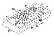
도 2를 참조하면, 본 발명에 따른 실시예의 사시도가 예시되어 있다. 본 실시예는 하나 이상의 근접 센서 및 본 발명에 따른 근접 센서(들)의 자기 교정 기능을 수행하는 역량을 갖는 어떠한 형태의 휴대용 전자 장치(201)라도 될 수 있다. 휴대용 전자 장치(201)의 예는 셀룰러 기반의 이동 전화기, WLAN 기반의 이동 전화기, 노트북 또는 랩톱 컴퓨팅 장치, 개인 휴대 정보 단말기, 개인용 내비게이션 장치, 터치 스크린 입력 장치, 펜 기반의 입력 장치, 및 휴대용 비디오 및/또는 오디오 플레이어 등을 포함하지만, 이것으로 제한되는 것은 아니다.2, a perspective view of an embodiment according to the present invention is illustrated. This embodiment may be any type of portable
일 실시예의 경우, 휴대용 전자 장치(201)는 터치 스크린 기능을 포함할 수 있는 가시(visible) 디스플레이(205)를 포함하는 전면(203)을 포함하는 하우징을 갖는다. 다른 실시예에서, 휴대용 전자 장치(201)는 디스플레이(205)와 관련되는 다수의 입력 키를 포함할 수 있다. 또 다른 실시예에서, 휴대용 전자 장치(201)는 전면(203)에 오디오 출력 및 입력용 개구부(207, 209)를 포함할 수 있다. 휴대용 전자 장치(201)는 각종 상이한 디스플레이 및 인터페이스 조합을 포함할 수 있음이 이해될 것이다.In one embodiment, the portable
전면(203) 외에, 휴대용 전자 장치(201)의 하우징은 상면(211), 저면(213), 측면(215, 217), 및 후면(219)을 또한 포함할 수 있다. 휴대용 전자 장치(201)의 하우징의 상면(211), 저면(213), 측면(215, 217)은 전면 및 후면(203 및 219)과 관련된 어떤 특정한 형상 또는 구성을 가질 필요는 없다.In addition to the
하우징의 전면(203), 상면(211), 저면(213), 측면(215, 217), 및 후면(219)은 하나 이상의 근접 센서를 지지할 수 있다. 일부 근접 센서는 하우징의 표면에 노출될 수 있지만, 어떤 형태의 근접 센서는 하우징의 표면 뒤에 숨겨진 채작용할 수 있음이 인식된다. 휴대용 전자 장치(201)가 둘 이상의 근접 센서를 포함하면, 이러한 근접 센서들은 환경(105) 조건의 검출 적용범위를 가장 넓게 극대화하기 위해 하우징의 여러 표면에 배치될 수 있다. 예를 들어, 근접 센서들은 한 센서가 제1 방향으로 지향되고 다른 센서가 제1 방향에 실질적으로 대향하는 제2 방향으로 지향될 수 있도록 대향면에 배치될 수 있다. 근접 센서들은 또한 하우징의 동일한 영역 또는 하우징에 의해 지지되는 동일한 기판에 공동 배치되지만, 상이한 방향으로 지향될 수 있다.The front 203, top 211, bottom 213,
도 3을 참조하면, 본 발명에 따른 실시예에 사용될 수 있는 예시적인 구성요소를 나타내는 블록도가 도시되어 있다. 본 예시적인 실시예는 하나 이상의 무선 송수신기(301), 프로세서(303), 메모리(305), 하나 이상의 출력 구성요소(307), 및 하나 이상의 입력 구성요소(309)를 포함한다. 각 실시예는 하나 이상의 출력 구성요소(307) 및 하나 이상의 입력 구성요소(309)를 포함하는 사용자 인터페이스를 포함할 수 있다. 각 무선 송수신기(301)는, 다음으로 제한되는 것은 아니지만, 셀룰러 송수신기(311)로 나타낸 바와 같이, 아날로그 통신(AMPS 이용), 디지털 통신(CDMA, TDMA, GSM, iDEN, GPRS, 또는 EDGE 이용), 및 차세대 통신(UMTS, WCDMA, LTE 또는 IEEE 802.16 이용) 및 이들의 변형예와 같은 통신용 무선 기술을 이용할 수 있다. 각 무선 송수신기(301)는 또한, 다음으로 제한되는 것은 아니지만, 홈RF(HomeRF), 블루투스 및 IEEE 802.11(a, b, g 또는 n)과 같은 피어-투-피어 또는 애드혹 통신과 같은 통신용 무선 기술; 및 WLAN 송수신기(313)로 나타낸 바와 같이 적외선 기술과 같은 다른 형태의 무선 통신을 이용할 수 있다. 또한, 각 송수신기(301)는 수신기, 송신기 또는 이들 둘 다일 수 있다.3, a block diagram illustrating exemplary components that may be used in embodiments in accordance with the present invention is shown. This example embodiment includes one or more
프로세서(303)는 하나 이상의 입력 구성요소(309) 및 하나 이상의 센서(315)로부터 수신된 정보에 기초하여 명령을 생성할 수 있다. 프로세서(303)는 수신된 정보를 단독으로 또는 메모리(305)에 저장된 정보와 같은 다른 데이터와 조합하여 처리할 수 있다. 따라서, 내부 구성요소(300)의 메모리(305)는 프로세서(303)에 의해 데이터를 저장 및 검색하는데 사용될 수 있다. 메모리(305)에 의해 저장될 수 있는 데이터는 오퍼레이팅 시스템, 애플리케이션, 및 데이터를 포함하지만, 이것으로 제한되는 것은 아니다. 각 오퍼레이팅 시스템은 내부 구성요소(300)의 구성요소들 간의 상호 작용, 각 송수신기(301) 및/또는 장치 인터페이스(아래 참조)를 통한 외부 장치와의 통신, 및 메모리(305)로 및 그 메모리로부터 애플리케이션 및 데이터의 저장 및 검색과 같은 휴대용 전자 장치의 기본적인 기능을 제어하는 실행가능한 코드를 포함한다. 각 애플리케이션은 오퍼레이팅 시스템을 이용하여 휴대용 전자 장치에 더 특정한 기능을 제공하는 실행가능한 코드를 포함한다. 데이터는 오퍼레이팅 시스템 또는 애플리케이션에 의해 휴대용 전자 장치의 기능을 실행하기 위해 참조되고/되거나 조작될 수 있는 비실행가능 코드 또는 정보이다. 예를 들어, 프로세서(303)는 메모리(305)에서 정보를 검색하여 센서(315)의 감도를 교정할 수 있다.The
내부 구성요소(300)의 입력 구성요소(309)는 광 센서(예컨대, 카메라)와 같은 비디오 입력 구성요소, 마이크로폰과 같은 오디오 입력 구성요소, 및 버튼 또는 키 선택 센서, 터치 패드 센서, 터치 스크린 센서, 용량성 센서, 움직임 센서, 및 스위치와 같은 기계적 입력 구성요소를 포함할 수 있다. 마찬가지로, 내부 구성요소(300)의 출력 구성요소(307)는 각종 비디오, 오디오 및/또는 기계적 출력을 포함할 수 있다. 예를 들면, 출력 구성요소(307)는 음극선관, 액정 디스플레이, 플라즈마 디스플레이, 백열등, 형광등, 전면 또는 후면 투사 디스플레이, 및 발광 다이오드 표시기와 같은 비디오 출력 구성요소를 포함할 수 있다. 출력 구성요소(307)의 다른 예는 스피커, 알람 및/또는 부저와 같은 오디오 출력 구성요소, 및/또는 진동 또는 움직임 기반 메커니즘과 같은 기계적 출력 구성요소를 포함한다.The
센서(315)는 입력 구성요소(309)와 유사하지만, 본 발명에서 이들의 중요성 때문에 특별히 도 3에서 별도로 나타낸다. 본 발명에 따른 휴대용 전자 장치(100)는 근접 물체의 존재를 검출하는 적어도 하나의 근접 센서(315)를 포함할 수 있다. 예를 들면, 도 2에 예시된 바와 같이, 센서(315)는, 다음으로 제한되는 것은 아니지만, 용량성 센서, 자기 센서, 유도성 센서, 광학/광전 센서, 레이저 센서, 음향/음파 센서, 레이더 기반 센서, 도플러 기반 센서, 온도 센서, 및 방사 기반의 근접 센서와 같은 하나 이상의 근접 센서(317)를 포함할 수 있다. 예를 들면, 근접 센서(317)는 적외선(IR)광 빔을 전송한 다음,반송된 반사 신호의 특성으로부터 어떤 근접 물체까지의 거리를 계산하는 적외선 근접 센서일 수 있다. 반송된 신호는 IR 광 다이오드를 이용하여 검출되어 변조된 IR 신호, 및/또는 삼각측량에 응답하는, 반사된 발광 다이오드(LED)의 광이 검출될 수 있다. 센서(315)는 또한 하나 이상의 다른 센서(319)를 포함할 수 있다. 이들 다른 센서(319)의 예는 가속도계, 터치 센서, 표면/하우징 용량성 센서, 오디오 센서, 및 비디오 센서(이를 테면 카메라)를 포함하지만, 이것으로 제한되는 것은 아니다. 예를 들면, 가속도계는 휴대용 전자 장치(201)의 전자 회로에 내장되어 수직 방위, 일정한 경사 및/또는 장치가 정지 상태인지를 보여줄 수 있다. 터치 센서는 장치가 측면(215, 217)에서 터치되는지를 나타내는데 사용되어, 특정한 방위 또는 이동이 사용자에 의해 의도된 것인지를 나타낼 수 있다.The
내부 구성요소(300)는 기능 추가 또는 개선을 위해 보조 구성요소 또는 부속품과의 직접적인 연결을 제공해 주는 장치 인터페이스(321)를 더 포함할 수 있다. 이 외에도, 내부 구성요소(300)는 바람직하게 전력을 다른 내부 구성요소에 제공하기 위해 휴대용 배터리와 같은 전원(323)을 포함하여 휴대용 전자 장치(101)의 휴대성을 가능하게 한다.The internal component 300 may further include a
도 3은 단지 예시 목적만을 위한 것이고 본 발명에 따른 휴대용 전자 장치의 구성요소를 예시하기 위해 제공된 것으로, 휴대용 전자 장치에 필요한 여러 구성요소의 개략적인 도면을 완벽하게 할 의도는 아님을 이해하여야 한다. 따라서, 휴대용 전자 장치는 도 3에 도시되지 않은 여러 다른 구성요소를 포함하거나, 또는 둘 이상의 구성요소의 조합 또는 특정 구성요소의 둘 이상의 개별 구성요소로의 분할을 포함할 수 있으며, 이는 여전히 본 발명의 범주 내에 있을수 있다.It is to be understood that FIG. 3 is for illustrative purposes only and is provided to illustrate the components of a portable electronic device according to the present invention and is not intended to be a complete schematic diagram of the various components required for the portable electronic device. Accordingly, the portable electronic device may include various other components not shown in FIG. 3, or may include a combination of two or more components or a division of a particular component into two or more individual components, which is still present invention. Be in the category of Can be.
도 4a를 참조하면, 본 발명에 따른 실시예의 제1 동작(400)을 나타내는 흐름도가 도시되어 있다. 이러한 제1 동작(400)에서, 휴대용 전자 장치(101)는 하나 이상의 근접 센서가 활성화되기 전마다 배경 측정치를얻는다. 단계(401)에서, 휴대용 전자 장치(101)의 하나 이상의 근접 센서(317)가 배경 측정치를 얻는다. 도 4a에 도시된 바와 같이, 배경 측정치는 검출 임계치에 대한 각 크기 측정 이전에 취해질 수 있다. 배경 측정치는 근접 센서(들)(317)에 의해 신호가 전송되지 않을 때의 수신 신호의 측정치이다. 다른 실시예의 경우, 배경 통계치가 누적되어 크기 측정치에 적합한 임계치를 결정하는데 사용될 수 있다. 누적된 통계치는 평균, 표준 편차, 최대 신호 레벨, 또는 최소 신호 레벨 중 적어도 하나를 포함한다. 그래서 임계치는 환경이 변화함에 따라 적응적으로 변할 수 있고, 따라서 배경 측정치에 반영된다. 크기 측정치가 임계치를 초과하는 동안 무작위 잡음 스파이크가 발생하면, 프로세서(303) 또는 근접 센서(317)는 크기 측정치가 손상되었는지 판단하기 위해 다른 센서(319)로부터 추가 정보를 얻을 수 있다.4A, a flow diagram illustrating a
단계(401)에서 배경 측정치를 얻은 후, 단계(403)에서 휴대용 전자 장치(101)는 배경 측정치가 하나 이상의 근접 센서(317)의 검출 임계치에 대한 조정을 정당화할지 판단할 수 있다. 휴대용 전자 장치(101)는 배경 측정치가 얻어질 때마다 검출 임계치를 갱신할 수 있지만, 검출 임계치의 조정은 배경 측정치의 변경을 표시할 때에만 필요할 수 있다. 휴대용 전자 장치(101)는 또한 배경 측정치가 기설정된 잡음 임계치를 초과하는 것으로 식별하여 검출 임계치를 조정할 것을 결정할 수 있다. 또한, 전술한 바와 같이, 휴대용 전자 장치(101)는 검출 임계치를 불필요하게 또는 부적절하게 조정하는 것을 방지하기 위해 근접 물체로부터의 이동을 무작위 잡음 스파이크 또는 손상 측정치와 구분할 수 있다.After obtaining the background measurement in
조정이 정당화되면, 단계(405)에서 휴대용 전자 장치(101)는 배경 측정치에 기초하여 하나 이상의 근접 센서(317)의 검출 임계치를 조정할 수 있다. 검출 임계치는 근접 센서(들)(317) 외에 다른 센서(319)에 의해 검출될 수 있는 환경 조건에 대한 근접 센서(317)의 감도와 연관된다. 또한, 다수의 근접 센서(317)에 동일한 검출 임계치가 이용되거나, 또는 상이한 근접 센서에 별도의 검출 임계치가 이용될 수 있다. 휴대용 전자 장치(101)는 근접 센서(들)(317)에 의한 배경 측정치와 관련하여 근접 센서와 다른 센서(319)로부터의 정보에 기초하여 적절한 검출 임계치를 결정할 수 있다. 근접 센서(들)(317)와 다른 센서(319)의 예는 터치 센서, 광 센서 또는 가속도계를 포함하지만, 이것으로 제한되는 것은 아니다. 휴대용 전자 장치(101)는 또한 근접 센서(들)(317)에 의한 배경 측정치와 함께 날짜 정보, 시간 정보, 또는 이들 둘 다에 기초하여 적절한 검출 임계치를 결정할 수 있다.If the adjustment is justified, in
휴대용 전자 장치(101)는 기설정된 부분, 백분율, 비율에 기초하여 검출 임계치를 조정하거나, 또는 배경 측정치에 기초하여 다른계산을 조정할 수 있다. 휴대용 전자 장치(101)는 또한, 이것으로 제한되는 것은 아니지만, 하루 중 시간, 사용 습관, 환경, 수신기 출력이 장시간 동안 변경되지 않았음을 보여주는 사용중 상태, 사용자가 잠자는 것으로 예상되는 하루 중 예측 시간 등과 같은, 다른 센서(319)로부터 수신되는 정보에 기초하여 훨씬 더 나은 검출 결과를 위해 검출 임계치를 낮게 동적으로 조정할 수 있다.The portable
근접 센서(들)(317)의 검출 임계치가 조정되는지 여부와 상관없이, 단계(407)에서 제1 동작(400)은 근접 센서의 조정된 검출 임계치에 기초하여 근접 센서에 의해 소스 신호를 방출하고, 단계(409)에서 근접 센서에 의해 소스 신호에 대응하는 반송 신호를 수신함으로써 계속된다. 단계(411)에서 휴대용 전자 장치(101)는 반송 신호에 기초하여 하나 이상의 기능을 수행할 수 있다. 예를 들면, 장치(101)는 근접한 사람의주목을 끌기 위해 오디오, 시각적 및/또는 기계적 표시기와 같은 출력 구성요소(307)를 활성화할 수 있다. 다른 예로서, 장치(101)는 근접한 물체의 이동이 검출되면 하나 이상의 기능을 활성화하거나 활성 상태를 유지하거나, 또는 그렇지 않고 이동이 검출되지 않으면 에너지 절약을 위해 기능을 비활성화한다. 그 후, 단계(401)에서 휴대용 전자 장치(101)는 다른 배경 측정치를 획득하거나 또는 단계(413)에서 기설정된 시간을 대기한 다음 다른 배경 측정치를 획득할 수 있다.Regardless of whether the detection threshold of the proximity sensor (s) 317 is adjusted, in
도 4b를 참조하면, 본 발명에 따른 실시예의 제2 동작(420)을 나타내는 다른 흐름도가 도시되고 있다. 이러한 제2 동작(420)에서, 휴대용 전자 장치(101)는 하나 이상의 근접 센서가 활성화될 때와 상관없이 배경 측정치를 획득한다. 단계(421)에서 각 근접 센서(317)는 소스 신호를 방출하고, 단계(423)에서 소스 신호에 대응하는 반송 신호를 수신할 수 있다. 단계(425)에서 기설정된 시간 후에, 장치(101)는 계속해서 반복적으로 소스 신호를 방출하고 반송 신호를 수신할 수 있다. 전술한 제1 동작(400)과 유사하게, 휴대용 전자 장치(101)는 단계(423) 이후에 반송 신호에 기초하여 하나 이상의 기능을 수행할 수 있다.Referring to FIG. 4B, another flow diagram illustrating a
개별적으로, 휴대용 전자 장치(101)는 주기적으로 근접 센서에 의해 배경 측정치를 획득할 수 있다. 단계(427)에서 배경 측정치를 획득한 후에, 단계(429)에서 휴대용 전자 장치(101)는 배경 측정치가 하나 이상의 근접 센서(317)의 검출 임계치에 대한 조정을 정당화하였는지 판단할 수 있다. 단계(429)에서 조정이 정당화되면, 단계(431)에서 휴대용 전자 장치(101)는 배경 측정치에 기초하여 하나 이상의 근접 센서(317)의 검출 임계치를 조정할 수 있다. 이러한 제2 동작(420)에서, 방출/수신 프로세스는 검출 임계치 조정 프로세스링크(435)를 가질 것이므로, 조정된 검출 임계치는 단계(421)에서 소스 신호가 방출된 다음에 이용될 수 있다. 마지막으로, 검출 임계치 조정 프로세스는 단계(433)에서 시간 지연을 가진 다음에 단계(427)에서 다음 배경 측정치를 획득할 수 있다.Individually, the portable
도 4c를 참조하면, 본 발명에 따른 실시예의 제3 동작(440)을 나타내는 또 다른 흐름도가 도시되어 있다. 이러한 제3 동작(440)에서, 휴대용 전자 장치(101)는 하나 이상의 근접 센서가 활성화되는기설정된 횟수 이후에, 또는 환경 조건의 변화를 검출하는 것에 응답하여배경 측정치를 획득한다.Referring to FIG. 4C, another flow diagram illustrating a
단계(441)에서 배경 측정치를 획득한 후에, 단계(443)에서 휴대용 전자 장치(101)는 배경 측정치가 하나 이상의 근접 센서(317)의 검출 임계치에 대한 조정을 정당화하였는지 판단할 수 있다. 조정이 정당화되면, 단계(445)에서 휴대용 전자 장치(101)는 배경 측정치에 기초하여 하나 이상의 근접 센서(317)의 검출 임계치를 조정할 수 있다. 근접 센서(들)(317)의 검출 임계치가 조정되는지 여부와 상관없이, 단계(447)에서 제3 동작(440)은 근접 센서의 조정된 검출 임계치에 기초하여 근접 센서에 의해 소스 신호를 방출하고, 단계(449)에서 근접 센서에 의해 소스 신호에 대응하는 반송 신호를 수신함으로써 계속된다. 전술한 제1 및 제2 동작(400, 420)과 유사하게, 단계(449) 이후에 휴대용 전자 장치(101)는 반송 신호에 기초하여 하나 이상의 기능을 수행할 수 있다.After acquiring the background measurement at step 441, the portable
그 후, 단계(451)에서 휴대용 전자 장치(101)는 다른 배경 측정치가 획득되어야 하는지 판단할 수 있다. 예를 들어, 장치(101)가 특정 개수의 소스 신호가 방출되고 특정 개수의 반송 신호가 수신된 후에 배경 측정치를 획득할 수 있도록,장치는 카운터를 포함할 수 있다. 다른 예로, 장치(101)는 근접 센서(들)(317) 외의 다른 센서(319)가 장치에 대한 환경 조건의 변화를 나타내는 정보를 제공하는 경우에만 배경 측정을개시한다. 제3 동작(440)은 배경 체크를 원하면 단계(441)에서 계속되고, 제3 동작은 배경 체크를 필요로 하지 않으면 단계(447)에서 계속된다. 또한, 휴대용 전자 장치(101)는 단계(453) 또는 단계(455)에서 기설정된 시간을 대기한 다음 다른 배경 측정치를 획득하거나 다른 소스 신호를 방출할 수 있다.Thereafter, in
예시적인 동작은 다음과 같은 가능한 시나리오로 나타낼 수 있다. 사용자는 테이블 위에 휴대용 전자 장치(101)를 놓고, 사용자는 그 휴대용 전자 장치를 그곳에 둔 채 그곳을 벗어날 수 있다. 사용자(107)가 장치(101)에 접근할 때, 장치는저전력 모드에서 사용자 존재 및 사용자가 어느 측면으로 접근하는지를 검출한다. 저전력 모드는, 예를 들어, 펄스 간의 지속시간 확장, 고 피크 전송과 같은 고감도, 및/또는 광폭 신호, 예컨대, LED, 펄스에 의해 성취될 수 있다. 휴대용 전자 장치(101)는 수평면(103) 상에서 고정 상태임을 검출하고 그 방위를 검출한다. 방위와 관련하여, 가속도계는 예를 들어 변화를 검출할 수 없고 장치가 뒤집혀 있는지 또는 똑바로 있는지를 나타낼 수 있으며, 터치 센서는 그 접촉이나 접촉 없음을 검출할 수 있다. 그 다음 장치(101)는 근접 센서에서의 버스트를 최대 전력 또는 기설정된 고 전력 레벨에서 개시한다. 장치(101)가 두 개보다 많은 근접 센서를 포함하면, 장치의 방위에 기초하여 활성화 또는 활성 상태를 유지할 근접 센서들이 선택된다. 이러한 시나리오에 대해 장치(101)가 사용자로부터 멀리 떨어져 있다고 예상되기 때문에, 최대 또는 고 레벨의 전력 버스트가 인에이블될 수 있다. 버스팅은 바로, 즉, 장치(101)를 놓자마자 또는 특정 시간 지연 후에 개시되어 근접 센서의 수신기가 정지/배경 반송을 측정하기 시작하는기회를 증가시킬 수 있다.Exemplary operations can be represented by the following possible scenarios. The user may place the portable
도 5를 참조하면, 본 발명에 따른 실시예의 예시적인 동작(500)의 결과를 예시하는 그래픽 표현도가 도시되어 있다. 이 그래픽 표현도의 수평축(501)은 초 단위의 시간을 나타내고, 이 그래픽 표현도의 수직축(503)은 볼트 단위의 출력을 나타낸다. 이와 같은 동작(500)에서, 휴대용 전자 장치(101)의 동작은 컨텍스트(context)를 기반으로 하고, 이 경우 장치는 수평면(103) 상에 배치된다. 또한, 이러한 동작(500)의 경우, 휴대용 전자 장치(101)는 제1 측면(215)에서 제1 근접 센서(505) 및 제1 측면에 대향하는 제2 측면(217)에서 제2 근접 센서(507)와 같이, 대향 측면에서 근접 센서(317)를 포함한다. 도 5에서, 제1 측면(215)의 제1 근접 센서(505)는 "우측 RX"로 식별되고, 제2 측면(217)의 제2 근접 센서(507)는 "좌측 RX"로 식별된다.5, a graphical representation is shown illustrating the results of
프로세서(303)는 두 근접 센서(505, 507)의 수신기 출력을 판독하고, 계속해서 판독치를 주기적으로 취한다. 그 다음 프로세서(303)는 각 출력마다, 유사한, 또는 사전 규정된 범위 내에 있는 값을 관찰한다. 이러한 판독치들은 회로 바이어스, 배경 간섭/조명, 및/또는 사용자의존재에 대응한다. 본 동작(500)에서 "1"이라는 판독치는 거의 일정하며 사용자(또는 그 외 누구든)가 휴대용 전자 장치(101)에서 멀어지는 상황을 나타내야 할 것이다. 그 다음 프로세서(303)는 사용자 검출 임계치를 "1"이라는백분율로 설정하고, 즉, 자체적으로 자기 교정한다. 프로세서(303)는 또한 사용자가 장치(101)에 의해 검출되는 측면을 검출한다. 예를 들어, 검출된 측면을 판단하면 사용자가 가까이 올 때 사용자 방향으로 오디오를 향하게 하거나 이미지를 회전시키는데 사용될 수 있다. 이것은 두 근접 센서(505, 507)의 수신기 출력을 고찰함으로써 행해진다.The
프로세서(303)는 다수의 근접 센서에 대해 동일한 검출 임계치를 이용하거나 또는 여러 근접 센서에 대해 개별의 검출 임계치를 이용할 수 있다. 예를 들어, 제1 근접 센서(505)의 우측 검출 임계치는 1.00볼트+델타일 수 있다. 따라서, 델타가, 예를 들어, 1/10 또는 10%로 미리 기설정되면, 우측 검출 임계치는 1.1볼트의 출력으로 설정될 수 있다. 다른 예로, 제2 근접 센서(507)의 좌측 검출 임계치는 1.20볼트+델타일 수 있다. 따라서, 델타가 다시 1/10 또는 10%로 기설정되면, 좌측 검출 임계치는 1.32볼트의 출력으로 설정될 수 있다.The
도 5에 나타낸 실시예의 경우, 프로세서(303)는 처음 3초의 동작 동안, 제1 근접 센서(505)에서 1.00볼트의 전압 판독치(509) 및 제2 근접 센서(507)에서 1.20볼트의 전압 판독치(511)를 측정한다. 이들 제1 및 제2 전압 판독치(509, 511)의 특성이 불변이라는 것은 장치(101) 주변의 환경(105)에서 물체에 의한 이동이 근접 센서(505, 507)에 의해 검출되지 않음을 나타낸다. 예를 들어, 사용자(107)는 처음 3초 동안 휴대용 전자 장치(101)에서 멀리 떨어져 있을 수 있다.For the embodiment shown in FIG. 5, the
다음 2초, 즉, 4초 및 5초의 동작 동안, 제1 근접 센서(505)의 전압 판독치(513, 515)는 1.30볼트로 증가하여 안정 상태가 됨으로써, 제1 근접 센서가 그 2초 시간 동안 상당히 이동하였다고검출함을 나타낸다. 그 동일한 시간 동안, 제2 근접 센서(507)의 전압 판독치(517)는 1.22볼트로 약간 상승한 다음 제2 근접 센서의 다른 전압 판독치(519)는 1.21볼트로 훨씬 더 조금 감소하게 된다. 제2 근접 센서(507)에서의 약간의 검출은 자체적으로 고려해 볼 때 센서에 근접하는 물체, 즉, 사용자의 어떤 형태의 검출을 반드시 나타내는 것은 아닐 것이다. 그러나, 이와 같은 제2 근접 센서(507)의 약간의 검출은 제1 근접 센서(505)의 검출과 함께 고려될 때 이들 두 판독치는 두 근접 센서에 의해 이동이 검출됨을 나타내고, 여기서 장치(101)에 대한 검출된 물체의 위치는 센서가 백분율이 더 크게 변한다고 검출함에 따라 결정될 수 있다. 예를 들어, 사용자(107)는 2초 동안 휴대용 전자 장치(101)의 우측면(217)을 지나 걸어갈 수 있고, 이것은 우측면(217)의 근접 센서에 의해 검출될 수 있다. 사용자(107)의 우측면(217)을 지나는 이동은 또한 작은교란을 일으킬 수 있으며, 이것은 좌측면(215)의 근접 센서에 의해 검출될 수 있다.During the next two seconds of operation, i.e., 4 and 5 seconds, the
다음 2초, 즉, 6초 및 7초의 동작 동안, 제1 근접 센서(505)의 전압 판독치(521, 523)는 이전 전압 레벨, 즉, 1.00 볼트로 다시 감소하여 안정 상태가 됨으로써, 제1 근접 센서가 그 2초 시간 동안 이동을 더 이상 검출하지 않음을 나타낸다. 그 동일한 시간 동안, 제2 근접 센서(507)의 전압 판독치(525, 527)는 2.00 볼트로 상당히 증가하여 안정 상태가 된다. 제2 근접 센서(507)에 의한 신호 검출의 상당한 증가는 더 큰 에너지 움직임 또는 휴대용 전자 장치(101)의 제2 측면(217)에서 다수의 물체에 의한 움직임을 나타낸다. 또한, 두 근접 센서(505, 507)에 의해 변화가 검출된이전의 시간과 대조적으로, 제2 근접 센서에 의한 검출 및 제1 근접 센서에 의한 검출 없음은 모든 검출 움직임이 장치(101)의 제2 측면(217)에 있음을 나타낸다. 예를 들어, 사용자(107)는 2초 동안 휴대용 전자 장치(101)의 좌측면(215)을 지나 더 걸을 수 있다.During the next two seconds, i.e., six and seven seconds of operation, the
마지막 2초, 즉, 8초 및 9초의 동작 동안, 제1 근접 센서(505)의 전압 판독치는 변경되지 않고 유지되며 제2 근접 센서(507)의 전압 판독치(529 및 531)는 이전의 초기 전압 레벨, 즉, 1.2 볼트로 다시 감소하여 안정 상태를 유지한다. 따라서, 두 근접 센서(505, 507)의 수신기 출력은 근접 센서가 그 2초 시간 동안 이동을 더 이상 검출하지 않음을 나타낸다. 예를 들어, 사용자(107)는 휴대용 전자 장치(101)에서 멀리 떨어져 더 이동했을 수 있다. 배경이 방과 같은 새로운 레벨로 변경되거나 또는 환경이 광원에 의해 조명되면, 센서는 비교적 일정하게 유지되는 광이 갑자기 증가하는 것을나타내야 하고, 이것은 환경의 변화가 사용자의 존재와 달리 배경에 기인한 것임을 나타낸다.During the last two seconds of operation, 8 and 9 seconds, the voltage readings of the
배경 측정치는 검출 임계치에 대한 매 크기 측정 전에 취해질 수 있다. 배경 측정치는 신호가 전송되지 않을 때의 수신된 신호의 측정치이다. 배경 측정치는 잡음 측정치를 제공한다. 배경 통계치(예를 들어, 평균, 표준 편차, 최대치, 최소치 등)가 누적되어 크기 측정에 적합한 임계치를 결정하는데 사용된다. 그래서 임계치는 환경이 변함에 따라 적응적으로 변할 수 있으며 배경 측정치에 반영된다. 크기 측정치가 임계치를 초과하는 동안 무작위 잡음 스파이크가 발생하면, 예를 들어, 사전 규정된 펄스 스트림 또는 코드를 찾을 수 있는 코딩은 크기 측정치가 손상되는지를 알기 위해 부가 정보를 제공할 것이다.Background measurements may be taken before every size measurement for the detection threshold. Background measurements are measurements of the received signal when no signal is transmitted. Background measurements provide noise measurements. Background statistics (eg, mean, standard deviation, maximum, minimum, etc.) are accumulated and used to determine the appropriate threshold for size measurements. Thus, the threshold can change adaptively as the environment changes and is reflected in background measurements. If a random noise spike occurs while the magnitude measurement exceeds the threshold, for example, a coding that can find a predefined pulse stream or code will provide additional information to see if the magnitude measurement is compromised.
도 6을 참조하면, 코딩 회로(600)는 배경 잡음의 영향을 최소화하도록 구현될 수 있다. 회로(600)에 의한 코딩은 수신기가 코딩 펄스의 타이밍을 알고 있는 다중 코딩 펄스를 전송하고, 특정 신호가 적절한 시간에 반송 또는 수신된 신호(601)에 존재하는지 여부를 체크함으로써 수행된다. 예를 들어, 근접 센서는 네 개의 코딩 펄스를 전송할 수 있고, 코딩 회로는 반송 신호의 코딩 펄스의 타이밍에 기초하여 이들 네 개의 코딩 펄스에 대응하는 반송 신호(601)의 유효성을 판단할 수 있다. 수신된 신호(601)의 펄스가 적절히 수신되면, 크기 측정치(603)는 유효한 것으로 고려되고; 그렇지 않으면 크기 측정치는 손상될 수 있다. 예를 들어, 광학 근접 센서는 다른 장치로부터의 광 플래시와 같은 환경에서의 외부 광원에 의해 손상될 수 있다. 크기 측정치(603)가 유효하면, 그 크기 측정치는 전술한 바와 같이 검출 임계치를 결정하는데 이용될 수 있다. 근접 센서의 검출 임계치는 후술하는 바와 같이 반송 신호가 기설정된 기준을 충족하거나 초과한다는 판단에 응답하여 크기 측정치에 기초하여 조정될 수 있다.Referring to FIG. 6, the
크기 측정치(603)는 코딩 펄스가 전송된 후 바로 취해진다. 샘플 및 홀드 회로(605)는 펄스 중 하나가 전송될 때 수신된 신호의 크기를 샘플링하는데 사용된다. 예를 들어, 샘플 및 홀드 회로로 피크 검출기가 이용될 수 있다. 샘플 및 홀드 회로(605)의 출력은 아날로그-디지털("A-to-D") 변환기(607)에 입력될 수 있다. 샘플 및 홀드 회로(605)는 도 6에 도시된 바와 같이 A-to-D 변환기(607)와 별개일 수 있거나, 또는 이 회로는 A-to-D 변환기에 통합될 수 있다. 샘플 및 홀드 회로(605)는 A-to-D 변환기(607)의 타이밍 요건을 줄여주는데 사용될 수 있다. 전송된 코딩 펄스의 폭은 샘플 및 홀드 회로(605)가 펄스가 전송된 타이밍을 인식하기 때문에 최소화될 수 있고, 이것은 결과적으로 송신기와 같이 상당량의 전류를 소모하는 구성요소의 전류 드레인을 줄여준다.The
코딩 회로(600)는 또한 신호 유효성(609) 뿐만 아니라 크기 측정치(603)를 체크할 수 있다. 코딩 회로(600)는 다중 펄스의 타이밍에 기초하여 반송 신호가 기설정된 기준을 충족하거나 초과하는지 판단한다. 예를 들면, 도 6에 예시된 바와 같이, 신호 유효성(609)은 크기 측정치(603)와 동시에 체크될 수 있으며, 이들 두 가지 체크는 수신된 신호(601)에 기반할 수 있다. 코딩 펄스를 수신하기 위하여, 수신된 신호(601)는 비교기(611)에 입력되고, 마이크로프로세서(613)의 GPIO 라인에 입력되는 디지털 신호로 변환될 수 있다. 그 다음 마이크로프로세서(613)는 적절한 시간에 GPIO 라인을 판독하여 코딩 펄스가 존재하는지 판단한다. (예를 들어, A-to-D 변환기(607) 대신에) 코딩 펄스를 식별하기 위해 비교기(611)를 이용하면 완전한 측정을 수행할 때 속도를 극대화하여, 전류 드레인을 줄여준다. 마이크로프로세서(613)는 선택사양으로 성능을 더욱 극대화하고 전류 드레인을 극소화하기 위해 저 수신 신호 레벨에서의 코드 이용을 방지할 수 있다.The
전술한 바에 따르면, 코딩 회로(600)는 두 가지 기능을 수행한다. 한 기능에서, 다중 전송 코딩 펄스가 샘플 및 홀드 회로(605)를 통해 단일 광폭 펄스로서 함께 연결되어 수신 신호 세기, 즉, 크기 측정치(603)를 측정하는데 사용된다. 결과적인 광폭 펄스 진폭은 신호 세기에 따라 변경되어 휴대용 전자 장치로부터의 사용자 거리를 평가하는데 사용된다. 다른 기능에서, 다중 펄스는 그 출력이 디지털 신호인 비교기(611)에 인가된다. 디지털 신호는 마이크로프로세서(613)가 무작위 잡음 에지 대신에 설정된 간격 내에서 다중 펄스를 계수(count)하기 때문에 그 디지털 신호가 유효 신호임을 나타내는 다중 디지털 펄스를 보일 수 있다. 따라서, 오류(falsing)가 최소화되며, 동시에 처리 및 검출 속도가 개선되고 전력 드레인이 최소화된다.As described above, the
도 7을 참조하면, 본 발명에 따른 근접 센서의 예시적인 실시예(700)를 예시하는 휴대용 전자 장치(201)의 단면도가 도시되어 있다. 본 실시예에서, 휴대용 전자 장치(201)는 한 쌍의 신호 방출기(703, 705) 및 하나 이상의 신호 수신기(707)를 지지하는 하우징(701)을 포함한다. 예를 들어, 휴대용 전자 장치(201)의 하우징(701)은 제1 신호 방출기(703), 제2 신호 방출기(705) 및 신호 수신기(707)를 지지할 수 있다. 대안으로, 하우징(701)은 한 쌍보다 많은 신호 방출기 및/또는 하나보다 많은 신호 수신기를 지지할 수 있다. 예를 들면, 휴대용 전자 장치(201)의 하우징(701)은 제1 신호 방출기(703), 제2 신호 방출기(705), 제3 신호 방출기(709), 제4 신호 방출기(711), 제1 신호 수신기(707) 및 제2 신호 수신기(713)를 지지할 수 있다.Referring to FIG. 7, there is shown a cross-sectional view of a portable
센서(319)와 같은 휴대용 전자 장치(201)의 센서는 하우징의 방위를 식별한다. 센서의 상태는 장치(201)의 전력 소모를 최소화하기 위해 근접 센서에 전력을 부여하거나 부여하지 않는다. 다음으로 제한되는 것은 아니지만 가속도계와 같이 가속도 및/또는 중력을 검출할 수 있는 어떠한 형태의 센서라도 하우징 방위를 식별하는데 사용될 수 있다. 휴대용 전자 장치(201)의 프로세서(303)는 센서에 의해 식별되는 하우징의 방위에 기초하여 제1 및 제2 신호 방출기 중 어느 것을 활성화할지 판단한다.Sensors in portable
전술한 바와 같이, 휴대용 전자 장치(201)는 제1 신호 방출기(703), 제2 신호 방출기(705), 및 하나 이상의 신호 수신기(707)를 포함한다. 제1 신호 방출기(703)는 제1 소스 신호를 제1 방향으로 향하게 하고, 제2 신호 방출기(705)는 제2 소스 신호를 제1 방향과 다른 제2 방향으로 향하게 한다. 신호 수신기 또는 수신기들(707)은 각기 제1 및 제2 소스 신호에 대응하는 제1 및 제2 반송 신호를 수신한다.As noted above, portable
전술한 바와 같이, 하우징(701)은 전면(203), 제1 측면(215), 제2 측면(217), 및 후면(219)을 포함한다. 하우징은 전면(203)으로 나타낸 제1 면, 및 제1 면과 실질적으로 대향하는 후면(219)으로 나타낸 제2 면을 포함한다. 센서(319)와 같은 휴대용 전자 장치(201)의 센서는 하우징의 방위를식별한다. 방위는 하우징(701)의 제1 면이 상향으로 지향되고 하우징의 제2 면이 하향으로 지향되는 제1 방위를 포함한다. 방위는 또한 후면(219)으로 나타낸 하우징(701)의 제2 면이 상향으로 지향되고, 전면(203)으로 나타낸 하우징의 제1 면이 하향으로 지향되는 제2 방위를 포함한다. 하우징(701)의 제1 면은 디스플레이(205)로 나타낸 사용자 인터페이스를 포함하고, 하우징의 제2 면에는 어떠한 사용자 인터페이스도 전혀 없다. 하우징(701)은 제1 측면(215)으로 나타낸 제3 면 및 제2 측면(217)으로 나타낸 제3 면과 실질적으로 대향하는 제4 면을 포함하고, 여기서 제3 및 제4 면은 제1 및 제2 면에 실질적으로 직교한다.As described above, the
휴대용 전자 장치(201)의 하우징(701)은 다수의 신호 방출기 쌍들 및/또는 다수의 신호 수신기를 지지할 수 있다. 예를 들어, 제1 신호 방출기(703), 제2 신호 방출기(705) 및 신호 수신기(707)는 하우징(701)의 제3 면, 즉, 표면(215)에 근접 배치될 수 있다. 이 외에도, 제3 신호 방출기(709), 제4 신호 방출기(711), 및 제2 신호 수신기(713)는 하우징(701)의 제4 면, 즉, 표면(217)에 근접 배치될 수 있고, 여기서 제4 면은 제3 면과 실질적으로 대향한다. 유사하게, 하우징(701)의 방위는 제1 및 제2 방위를 포함한다. 제1 방위의 경우, 제1 및 제3 신호 방출기(703, 709)는 상향으로 지향되지만 다른 방향들로 지향되고, 제2 및 제4 신호 방출기(705, 711)는 하향으로 지향되지만 다른 방향들로 지향된다. 제2 방위의 경우, 제2 및 제4 신호 방출기는 상향으로 지향되지만 다른 방향들로 지향되고, 제1 및 제3 신호 방출기는 하향으로 지향되지만 다른 방향들로 지향된다. 예를 들어, 도 7에 도시된 바와 같이, 제1 신호 방출기(703)는 하우징(701) 외부의 좌측 상단 영역으로 지향되고, 제2 신호 방출기(705)는 하우징 외부의 좌측 하단 영역으로 지향되고, 제3 신호 방출기(709)는 하우징 외부의 우측 상단 영역으로 지향되고, 제4 신호 방출기(711)는 하우징 외부의 우측 하단 영역으로 지향된다.The
본 발명에 따른 다른 실시예의 경우, 휴대용 전자 장치(201)의 하우징(701)은 다수의 신호 방출기에 부가하거나 그 대신에 다수의 신호 수신기를 지지할 수 있고, 여기서 장치의 방위에 기초하여 적절한 신호 수신기가 선택될 수 있다. 예를 들면, 하우징은 신호 방출기(703, 705, 709 및/또는 711)에 대해 도 7에 도시된 위치에서 제1, 제2, 제3 및/또는 제4 신호 수신기를 지지할 수 있다. 제1 신호 수신기는 소스 신호에 대응하는 반송 신호를 제1 방향으로부터 수신할 수 있고, 제2 신호 수신기는 소스 신호에 대응하는 반송 신호를 제1 방향과 다른 제2 방향으로부터 수신할 수 있다. 프로세서(303)는 센서(들)에 의해 식별되는 하우징의 방위에 기초하여 제1 및 제2 신호 수신기 중 어느 것을 활성화할지 판단할 수 있다.In another embodiment according to the present invention, the
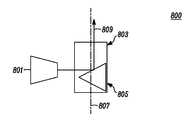
도 8을 참조하면, 본 발명에 따른 근접 센서의 다른 예시적인 실시예(800)가 도시되어 있으며, 여기서 하우징(701)의 방위에 기초하여 신호 방출기(801)로부터의 소스 신호를 적절한 방향으로 재지향되게 하는 메커니즘이 사용된다. 메커니즘은 신호 방출기(801)에 인접 배치된 구획(803), 및 그 구획에 의해 지지되는 반사기(805)를 포함한다. 반사기(805)는 반사기에 가해지는 중력에 기초하여, 후술하는 도 9 및 10에 예시된 구획(803)의 제1 및 제2 위치 사이에서 이동할 수 있다. 중력은 하우징의 방위가변경됨에 따라 변한다. 중력 구동 메커니즘은 장치가 상향 센서를 노출하지만 하향 센서를 가리는 표면 상에 배치될 수 있기 때문에 상향 지향된 방출기를 활성 상태로 유지하고 하향 지향된 방출기를 디스에이블하는데 사용된다. 중력 구동 메커니즘은 또한 단일 신호 방출기가 다수의 방향으로 지향되게 하고, 그럼으로써 각 근접 센서가 원하는 적용범위 영역에 필요한 다수의 신호 방출기 및 이들과 연관된 비용을 최소화할 수 있다. 또 다른 실시예에서, 가속도계는 상향 지향된 송신기 및/또는 수신기를 인에이블하고 상향 지향되지 않은 다른 송신기 및/또는 수신기를 디스에이블하는데 사용될 수 있다.Referring to FIG. 8, another
전술한 실시예와 유사하게, 하우징(701)의 제1 면은 디스플레이(205)로 나타낸 사용자 인터페이스를 포함할 수 있고, 하우징의 제2 면에는 어떠한사용자 인터페이스도 없다. 하우징(701)은 다수의 신호 방출기 쌍들 및/또는 다수의 신호 수신기를 더 포함할 수 있다.Similar to the embodiment described above, the first side of the
일 실시예의 경우, 구획(803)은 중공 보어(hollow bore)를 포함할 수 있고, 반사기(805)는 구획 내 제1 및 제2 위치 사이에서 이동할 때 중공 보어 내에서 미끄러져 이동할 수 있다. 구획(803)은 종축(807)을 따라 길게 연장될 수 있으며, 이 종축은 하우징(701)의 면(203, 219)으로 나타낸 제1 및 제2 면에 실질적으로 직교한다. 반사기(805)는 제1 및 제2 위치 사이에서 이동할 때 종축(807)을 따라 이동할 수 있다. 신호 방출기(801)로부터의 소스 신호(809)는 하우징(701)의 방위에 기초하여 반사기(805)에 의해 재지향될 수 있다.In one embodiment, the
본 발명에 따른 다른 실시예의 경우, 휴대용 전자 장치(201)의 하우징(701)은 반송 신호가 신호 수신기로 재지향될 수 있도록 하우징의 방위에 기초하여 소스 신호에 대응하는 반송 신호를 수신하기에 적합한 방향을 결정하는 구성요소를 지지할 수 있다. 예를 들면, 하우징(701)은 신호 방출기(801)를 위해 도 8에 도시된 위치에서 신호 수신기를 지지할 수 있다. 하우징(701)은 소스 신호에 대응하는 반송 신호를 제1 방향으로부터 수신하고 반송 신호를 신호 수신기로 재지향하는 신호 수신기에 대한 제1 위치를 갖는 신호 수신기에 인접하는 반사기(805)를 지지할 수 있다. 반사기는 또한 소스 신호에 대응하는 반송 신호를 제1 방향과 다른 제2 방향으로부터 수신하고 반송 신호를 신호 수신기로 재지향하는 신호 수신기에 대한 제2 위치를 가질 수 있다. 신호 방출기 또는 신호 수신기에 대한 반사기의 여러 위치뿐만 아니라, 소스 신호 및 반송 신호의 방향 변경에 대해서는 도 9 및 도 10에 대한 이하의 설명에서 예시된다.In another embodiment according to the present invention, the
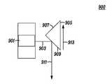
도 9를 참조하면, 도 8의 예시적인 실시예의 제1 위치(900)의 대표도가 도시되어 있다. 이러한 제1 위치(900)의 경우, 신호 방출기(901)는 소스 신호(903)를 반사기(905)로 지향시킨다. 도 9에 도시된 실시예에서, 반사기(905)는 형상이 삼각형이며 제1 반사면(907) 및 제2 반사면(909)을 포함한다. 반사기(905)는 구획(803) 내에서 신호 방출기(901)로부터의 소스 신호(903)를 제1 방향(911)으로 지향시키는 제1 위치(900)를 가질 수 있다. 제2 반사면(909)은 기울어져 있고 소스 신호(903)를 제2 반사면의 각도로 지향되어반사시킬 수 있다.Referring to FIG. 9, a representative view of
휴대용 전자 장치(201)는 중력의 영향을 받아 반사기(905)가 중력 방향(913)으로 이동하게 할 수 있다. 가장 일반적인 중력은 대체로 휴대용 전자 장치(201)에 대하여 하향으로 지향된다. 도 9에 도시된 실시예의 경우, 중력은 반사기(905) 위에 있고, 따라서 "하향" 중력은 도 9에서 실제로 상향이다. 하우징(701)의 제2 면이 상향으로 지향되고 하우징의 제1 면이 하향으로 지향될 때, 반사기는 중력 방향(913)으로 제1 위치(900)로 이동한다. 소스 신호(903)는 반사기(905)가 제1 위치(900)로 이동하는 것에 응답하여 제2 반사면(909)에서 반사한다.The portable
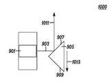
도 10을 참조하면, 도 8의 예시적인 실시예의 제2 위치(1000)의 대표도가 도시되어 있다. 이러한 제2 위치(1000)의 경우, 신호 방출기(901)는 소스 신호(903)를 반사기(905)로 지향시킨다. 반사기(905)는 구획(803) 내에서 신호 방출기(901)로부터의 소스 신호(903)를 제2 방향(1011)으로 지향시키는 제2 위치(1000)를 가질 수 있다. 제1 반사면(907)은 기울어져 있고 제1 반사면의 각도로 지향되어 소스 신호(903)를 반사할 수 있다.Referring to FIG. 10, a representative view of the
휴대용 전자 장치(201)는 중력의 영향을 받아 반사기(905)가 중력 방향(1013)으로 이동하게 할 수 있다. 도 9 및 도 10은 중력으로 구동되는 두 가지 가능한 반사기 위치를 도시한다. 휴대용 전자 장치의 방위와 관계없이, 신호 방출기(들)는 반사기가 중력으로 인해 하향으로 미끄러져 이동하기 때문에 반사기의 표면(907)과 같은 적절한 표면에서 반사시켜 항상 상향을 가리킨다. 휴대용 전자 장치의 방위가 변경되면, 즉, 장치가 뒤집혀 있으면, 신호 방출기(들)는 표면(909)과 같은 다른 표면에서 반사시켜 다시 상향을 가리킨다. 반사기(905)가 제2 위치(1000)로 이동할 때의 중력은 반사기가 제1 위치(900)로 이동할 때의 방향(913)과 다른데 그 이유는 중력은 하우징(701)의 방위가 변경됨에 따라 변하기 때문이다. 도 10에 도시된 실시예의 경우, 중력은 반사기(905) 아래에 있으므로, 하향 중력은 도 10에서 하향이다. 하우징(701)의 제1 면이 상향으로 지향되고 하우징의 제2 면이 하향으로 지향될 때, 반사기는 중력 방향(1013)으로 제2 위치(1000)로 이동한다. 소스 신호(903)는 반사기(905)가 제2 위치(1000)로 이동하는 것에 응답하여 제1 반사면(907)에서 반사된다. 구획 내에서 제2 위치는 신호 방출기로부터의 소스 신호를 제1 방향과 다른 제2 방향으로 지향시킨다.The portable
본 발명의 바람직한 실시예가 예시되고 설명되었지만, 본 발명은 이것으로 제한되지 않음을 이해하여야 한다. 당업자에게는 첨부의 특허청구범위에 규정된 바와 같은 본 발명의 정신 및 범주로부터 벗어나지 않고 많은 변형, 변경, 변동, 대체 및 등가물이 만들어질 것이다.While the preferred embodiments of the invention have been illustrated and described, it should be understood that the invention is not so limited. Many modifications, changes, variations, substitutions and equivalents will be made to those skilled in the art without departing from the spirit and scope of the invention as defined in the appended claims.
Claims (21)
Translated fromKorean하우징;
상기 하우징에 의해 지지되며, 상기 하우징의 방위(orientation)를 식별하는 적어도 하나의 센서;
상기 하우징에 의해 지지되며, 제1 소스 신호를 제1 방향으로 지향시키는 제1 신호 방출기;
상기 하우징에 의해 지지되며, 제2 소스 신호를 상기 제1 방향과 다른 제2 방향으로 지향시키는 제2 신호 방출기;
상기 하우징에 의해 지지되며, 각기 상기 제1 및 제2 소스 신호에 대응하는 제1 및 제2 반송(return) 신호를 수신하는 적어도 하나의 신호 수신기; 및
상기 하우징에 의해 지지되며, 상기 적어도 하나의 센서에 의해 식별된 상기 하우징의 방위에 기초하여 상기 제1 신호 방출기 및 제2 신호 방출기 중 어느 것을 활성화할지 판단하는 프로세서
를 포함하는 휴대용 전자 장치.A portable electronic device having one or more proximity sensors,
housing;
At least one sensor supported by the housing, the sensor identifying the orientation of the housing;
A first signal emitter supported by the housing and directing a first source signal in a first direction;
A second signal emitter supported by the housing and directing a second source signal in a second direction different from the first direction;
At least one signal receiver supported by the housing and receiving first and second return signals respectively corresponding to the first and second source signals; And
A processor supported by the housing and determining whether to activate the first signal emitter or the second signal emitter based on an orientation of the housing identified by the at least one sensor
Portable electronic device comprising a.
하우징;
상기 하우징에 의해 지지되며, 소스 신호를 방출하는 신호 방출기;
상기 신호 방출기로부터의 상기 소스 신호를 제1 방향으로 지향시키는 상기 신호 방출기에 대한 제1 위치와, 상기 신호 방출기로부터의 상기 소스 신호를 상기 제1 방향과 다른 제2 방향으로 지향시키는 상기 신호 방출기에 대한 제2 위치를 갖는 반사기; 및
상기 하우징에 의해 지지되며, 상기 소스 신호에 대응하는 반송(return) 신호를 수신하는 신호 수신기
를 포함하는 휴대용 전자 장치.A portable electronic device having one or more proximity sensors,
housing;
A signal emitter supported by the housing and emitting a source signal;
A first position relative to the signal emitter directing the source signal from the signal emitter in a first direction, and to the signal emitter directing the source signal from the signal emitter in a second direction different from the first direction A reflector having a second position relative to the reflector; And
A signal receiver supported by the housing and receiving a return signal corresponding to the source signal
Portable electronic device comprising a.
상기 신호 수신기에 인접 배치된 구획(compartment)을 더 포함하고,
상기 반사기는 상기 반사기에 가해지는 중력에 기초하여 상기 구획 내 상기 제1 위치와 제2 위치 사이에서 이동하는 휴대용 전자 장치.9. The method of claim 8,
Further comprising a compartment disposed adjacent the signal receiver,
And the reflector moves between the first and second positions in the compartment based on gravity applied to the reflector.
상기 신호 수신기에 인접 배치된 구획을 더 포함하고,
상기 구획은 중공(hollow) 또는 액체로 채워진 보어(liquid filled bore)를 포함하고;
상기 반사기는 상기 구획 내 상기 제1 위치와 제2 위치 사이에서 이동할 때 상기 보어 내에서 미끄러져 이동하는 휴대용 전자 장치.9. The method of claim 8,
Further comprising a compartment disposed adjacent said signal receiver,
The compartment comprises a hollow or liquid filled bore;
And the reflector slides in the bore as it moves between the first and second positions in the compartment.
상기 신호 수신기에 인접 배치된 구획을 더 포함하고,
상기 구획은 종축을 따라 길게 연장되며, 상기 종축은 상기 하우징의 상기 제1 및 제2 면에 실질적으로 직교하는 휴대용 전자 장치.The method of claim 12,
Further comprising a compartment disposed adjacent said signal receiver,
And the compartment extends along the longitudinal axis, the longitudinal axis being substantially orthogonal to the first and second surfaces of the housing.
하우징;
상기 하우징에 의해 지지되며, 상기 하우징의 방위를 식별하는 적어도 하나의 센서;
상기 하우징에 의해 지지되며, 소스 신호를 방출하는 적어도 하나의 신호 방출기;
상기 하우징에 의해 지지되며, 상기 소스 신호에 대응하는 반송 신호를 제1 방향으로부터 수신하는 제1 신호 수신기;
상기 하우징에 의해 지지되며, 상기 소스 신호에 대응하는 상기 반송 신호를 상기 제1 방향과다른 제2 방향으로부터 수신하는 제2 신호 수신기; 및
상기 하우징에 의해 지지되며, 상기 적어도 하나의 센서에 의해 식별된 상기 하우징의 방위에 기초하여 상기 제1 신호 수신기 및 제2 신호 수신기 중 어느 것을 활성화할지 판단하는 프로세서
를 포함하는 휴대용 전자 장치.A portable electronic device having one or more proximity sensors,
housing;
At least one sensor supported by the housing and identifying an orientation of the housing;
At least one signal emitter supported by the housing and emitting a source signal;
A first signal receiver supported by the housing and receiving a carrier signal corresponding to the source signal from a first direction;
The carrier signal supported by the housing and corresponding to the source signal is controlled in the first direction; A second signal receiver receiving from another second direction; And
A processor supported by the housing, the processor determining whether to activate the first signal receiver or the second signal receiver based on an orientation of the housing identified by the at least one sensor
Portable electronic device comprising a.
하우징;
상기 하우징에 의해 지지되며, 소스 신호를 방출하는 신호 방출기;
상기 하우징에 의해 지지되며, 상기 소스 신호에 대응하는 반송 신호를 수신하는 신호 수신기; 및
상기 소스 신호에 대응하는 상기 반송 신호를 제1 방향으로부터 수신하고 상기 반송 신호를 상기 신호 수신기로 재지향시키는 상기 신호 수신기에 대한 제1 위치와, 상기 소스 신호에 대응하는 상기 반송 신호를 상기 제1 방향과 다른 제2 방향으로부터 수신하고 상기 반송 신호를 상기 신호 수신기로 재지향시키는 상기 신호 수신기에 대한 제2 위치를 갖는 반사기
를 포함하는 휴대용 전자 장치.A portable electronic device having one or more proximity sensors,
housing;
A signal emitter supported by the housing and emitting a source signal;
A signal receiver supported by the housing and receiving a carrier signal corresponding to the source signal; And
A first position for the signal receiver that receives the carrier signal corresponding to the source signal from a first direction and redirects the carrier signal to the signal receiver, and the carrier signal corresponding to the source signal to the first direction A reflector having a second position with respect to the signal receiver that receives from a second direction different from and redirects the carrier signal to the signal receiver
Portable electronic device comprising a.
21. The portable electronic device of claim 20, further comprising a compartment disposed adjacent the signal receiver, wherein the reflector is supported by the compartment in both the first and second positions.
Applications Claiming Priority (3)
| Application Number | Priority Date | Filing Date | Title |
|---|---|---|---|
| US12/347,146 | 2008-12-31 | ||
| US12/347,146US8275412B2 (en) | 2008-12-31 | 2008-12-31 | Portable electronic device having directional proximity sensors based on device orientation |
| PCT/US2009/066639WO2010077558A2 (en) | 2008-12-31 | 2009-12-03 | Portable electronic device having directional proximity sensors based on device orientation |
Publications (2)
| Publication Number | Publication Date |
|---|---|
| KR20110102937A KR20110102937A (en) | 2011-09-19 |
| KR101239435B1true KR101239435B1 (en) | 2013-03-06 |
Family
ID=42285608
Family Applications (1)
| Application Number | Title | Priority Date | Filing Date |
|---|---|---|---|
| KR1020117018062AActiveKR101239435B1 (en) | 2008-12-31 | 2009-12-03 | Portable electronic device having directional proximity sensors based on device orientation |
Country Status (5)
| Country | Link |
|---|---|
| US (2) | US8275412B2 (en) |
| EP (2) | EP2731271B1 (en) |
| KR (1) | KR101239435B1 (en) |
| CN (2) | CN104253887B (en) |
| WO (1) | WO2010077558A2 (en) |
Families Citing this family (183)
| Publication number | Priority date | Publication date | Assignee | Title |
|---|---|---|---|---|
| US7623028B2 (en) | 2004-05-27 | 2009-11-24 | Lawrence Kates | System and method for high-sensitivity sensor |
| US8033479B2 (en) | 2004-10-06 | 2011-10-11 | Lawrence Kates | Electronically-controlled register vent for zone heating and cooling |
| US7747293B2 (en)* | 2006-10-17 | 2010-06-29 | Marvell Worl Trade Ltd. | Display control for cellular phone |
| US8160752B2 (en) | 2008-09-30 | 2012-04-17 | Zome Networks, Inc. | Managing energy usage |
| US10447334B2 (en) | 2008-07-09 | 2019-10-15 | Secureall Corporation | Methods and systems for comprehensive security-lockdown |
| US9642089B2 (en) | 2008-07-09 | 2017-05-02 | Secureall Corporation | Method and system for planar, multi-function, multi-power sourced, long battery life radio communication appliance |
| US10128893B2 (en) | 2008-07-09 | 2018-11-13 | Secureall Corporation | Method and system for planar, multi-function, multi-power sourced, long battery life radio communication appliance |
| US11469789B2 (en) | 2008-07-09 | 2022-10-11 | Secureall Corporation | Methods and systems for comprehensive security-lockdown |
| EP2356529A1 (en)* | 2008-10-28 | 2011-08-17 | Earth Aid Enterprises Llc | Methods and systems for determining the environmental impact of a consumer's actual resource consumption |
| US8030914B2 (en)* | 2008-12-29 | 2011-10-04 | Motorola Mobility, Inc. | Portable electronic device having self-calibrating proximity sensors |
| US8275412B2 (en)* | 2008-12-31 | 2012-09-25 | Motorola Mobility Llc | Portable electronic device having directional proximity sensors based on device orientation |
| US8754775B2 (en) | 2009-03-20 | 2014-06-17 | Nest Labs, Inc. | Use of optical reflectance proximity detector for nuisance mitigation in smoke alarms |
| US20100271312A1 (en)* | 2009-04-22 | 2010-10-28 | Rachid Alameh | Menu Configuration System and Method for Display on an Electronic Device |
| US20100271331A1 (en)* | 2009-04-22 | 2010-10-28 | Rachid Alameh | Touch-Screen and Method for an Electronic Device |
| US8355887B1 (en) | 2009-04-24 | 2013-01-15 | Cypress Semiconductor Corporation | Proximity based gesturing devices, systems and methods |
| US8269175B2 (en)* | 2009-05-22 | 2012-09-18 | Motorola Mobility Llc | Electronic device with sensing assembly and method for detecting gestures of geometric shapes |
| US8542186B2 (en) | 2009-05-22 | 2013-09-24 | Motorola Mobility Llc | Mobile device with user interaction capability and method of operating same |
| US8304733B2 (en) | 2009-05-22 | 2012-11-06 | Motorola Mobility Llc | Sensing assembly for mobile device |
| US8788676B2 (en)* | 2009-05-22 | 2014-07-22 | Motorola Mobility Llc | Method and system for controlling data transmission to or from a mobile device |
| US8619029B2 (en)* | 2009-05-22 | 2013-12-31 | Motorola Mobility Llc | Electronic device with sensing assembly and method for interpreting consecutive gestures |
| US8391719B2 (en) | 2009-05-22 | 2013-03-05 | Motorola Mobility Llc | Method and system for conducting communication between mobile devices |
| JP5282661B2 (en)* | 2009-05-26 | 2013-09-04 | ソニー株式会社 | Information processing apparatus, information processing method, and program |
| US8319170B2 (en) | 2009-07-10 | 2012-11-27 | Motorola Mobility Llc | Method for adapting a pulse power mode of a proximity sensor |
| CN102005098A (en)* | 2009-08-31 | 2011-04-06 | 鸿富锦精密工业(深圳)有限公司 | Electronic device with alert function and alert method of electronic device |
| KR20110033643A (en)* | 2009-09-25 | 2011-03-31 | 삼성전자주식회사 | Power control method and device of a Bluetooth headset |
| KR101624920B1 (en)* | 2009-11-16 | 2016-05-27 | 삼성전자주식회사 | Apparatus and method for calling of a portable terminal |
| US8665227B2 (en)* | 2009-11-19 | 2014-03-04 | Motorola Mobility Llc | Method and apparatus for replicating physical key function with soft keys in an electronic device |
| US20110221607A1 (en)* | 2010-03-15 | 2011-09-15 | Microsoft Corporation | Dynamic Device Adaptation Based on Proximity to Other Devices |
| US8963845B2 (en) | 2010-05-05 | 2015-02-24 | Google Technology Holdings LLC | Mobile device with temperature sensing capability and method of operating same |
| US9103732B2 (en) | 2010-05-25 | 2015-08-11 | Google Technology Holdings LLC | User computer device with temperature sensing capabilities and method of operating same |
| US8751056B2 (en) | 2010-05-25 | 2014-06-10 | Motorola Mobility Llc | User computer device with temperature sensing capabilities and method of operating same |
| US20110300901A1 (en)* | 2010-06-02 | 2011-12-08 | Microsoft Corporation | Intelligent Input Handling |
| KR101678390B1 (en)* | 2010-06-04 | 2016-11-23 | 삼성전자 주식회사 | Apparatus and method for driving of communication terminal |
| US20110310005A1 (en)* | 2010-06-17 | 2011-12-22 | Qualcomm Incorporated | Methods and apparatus for contactless gesture recognition |
| US8606374B2 (en) | 2010-09-14 | 2013-12-10 | Nest Labs, Inc. | Thermodynamic modeling for enclosures |
| US8727611B2 (en) | 2010-11-19 | 2014-05-20 | Nest Labs, Inc. | System and method for integrating sensors in thermostats |
| US8510255B2 (en) | 2010-09-14 | 2013-08-13 | Nest Labs, Inc. | Occupancy pattern detection, estimation and prediction |
| US8918219B2 (en) | 2010-11-19 | 2014-12-23 | Google Inc. | User friendly interface for control unit |
| US9104211B2 (en) | 2010-11-19 | 2015-08-11 | Google Inc. | Temperature controller with model-based time to target calculation and display |
| US8950686B2 (en) | 2010-11-19 | 2015-02-10 | Google Inc. | Control unit with automatic setback capability |
| US8519885B2 (en)* | 2011-09-21 | 2013-08-27 | Mobile Joose, Inc. | Combination hand-held phone and radar system |
| US8559869B2 (en) | 2011-09-21 | 2013-10-15 | Daniel R. Ash, JR. | Smart channel selective repeater |
| US8954290B2 (en)* | 2010-09-30 | 2015-02-10 | Fitbit, Inc. | Motion-activated display of messages on an activity monitoring device |
| US9148483B1 (en) | 2010-09-30 | 2015-09-29 | Fitbit, Inc. | Tracking user physical activity with multiple devices |
| US8738321B2 (en) | 2010-09-30 | 2014-05-27 | Fitbit, Inc. | Methods and systems for classification of geographic locations for tracked activity |
| US9310909B2 (en) | 2010-09-30 | 2016-04-12 | Fitbit, Inc. | Methods, systems and devices for physical contact activated display and navigation |
| US9390427B2 (en) | 2010-09-30 | 2016-07-12 | Fitbit, Inc. | Methods, systems and devices for automatic linking of activity tracking devices to user devices |
| US8620617B2 (en) | 2010-09-30 | 2013-12-31 | Fitbit, Inc. | Methods and systems for interactive goal setting and recommender using events having combined activity and location information |
| US10004406B2 (en) | 2010-09-30 | 2018-06-26 | Fitbit, Inc. | Portable monitoring devices for processing applications and processing analysis of physiological conditions of a user associated with the portable monitoring device |
| US8738323B2 (en) | 2010-09-30 | 2014-05-27 | Fitbit, Inc. | Methods and systems for metrics analysis and interactive rendering, including events having combined activity and location information |
| US9241635B2 (en) | 2010-09-30 | 2016-01-26 | Fitbit, Inc. | Portable monitoring devices for processing applications and processing analysis of physiological conditions of a user associated with the portable monitoring device |
| US8805646B2 (en) | 2010-09-30 | 2014-08-12 | Fitbit, Inc. | Methods, systems and devices for linking user devices to activity tracking devices |
| US8744803B2 (en) | 2010-09-30 | 2014-06-03 | Fitbit, Inc. | Methods, systems and devices for activity tracking device data synchronization with computing devices |
| US8762101B2 (en) | 2010-09-30 | 2014-06-24 | Fitbit, Inc. | Methods and systems for identification of event data having combined activity and location information of portable monitoring devices |
| US9253168B2 (en) | 2012-04-26 | 2016-02-02 | Fitbit, Inc. | Secure pairing of devices via pairing facilitator-intermediary device |
| US10983945B2 (en) | 2010-09-30 | 2021-04-20 | Fitbit, Inc. | Method of data synthesis |
| US8954291B2 (en) | 2010-09-30 | 2015-02-10 | Fitbit, Inc. | Alarm setting and interfacing with gesture contact interfacing controls |
| US8762102B2 (en) | 2010-09-30 | 2014-06-24 | Fitbit, Inc. | Methods and systems for generation and rendering interactive events having combined activity and location information |
| US8712724B2 (en) | 2010-09-30 | 2014-04-29 | Fitbit, Inc. | Calendar integration methods and systems for presentation of events having combined activity and location information |
| US8615377B1 (en) | 2010-09-30 | 2013-12-24 | Fitbit, Inc. | Methods and systems for processing social interactive data and sharing of tracked activity associated with locations |
| US8694282B2 (en) | 2010-09-30 | 2014-04-08 | Fitbit, Inc. | Methods and systems for geo-location optimized tracking and updating for events having combined activity and location information |
| US11243093B2 (en) | 2010-09-30 | 2022-02-08 | Fitbit, Inc. | Methods, systems and devices for generating real-time activity data updates to display devices |
| US9714772B2 (en) | 2010-11-19 | 2017-07-25 | Google Inc. | HVAC controller configurations that compensate for heating caused by direct sunlight |
| US8850348B2 (en) | 2010-12-31 | 2014-09-30 | Google Inc. | Dynamic device-associated feedback indicative of responsible device usage |
| US9075419B2 (en) | 2010-11-19 | 2015-07-07 | Google Inc. | Systems and methods for a graphical user interface of a controller for an energy-consuming system having spatially related discrete display elements |
| US9448567B2 (en) | 2010-11-19 | 2016-09-20 | Google Inc. | Power management in single circuit HVAC systems and in multiple circuit HVAC systems |
| US9459018B2 (en) | 2010-11-19 | 2016-10-04 | Google Inc. | Systems and methods for energy-efficient control of an energy-consuming system |
| US10346275B2 (en) | 2010-11-19 | 2019-07-09 | Google Llc | Attributing causation for energy usage and setpoint changes with a network-connected thermostat |
| US9256230B2 (en) | 2010-11-19 | 2016-02-09 | Google Inc. | HVAC schedule establishment in an intelligent, network-connected thermostat |
| US9453655B2 (en) | 2011-10-07 | 2016-09-27 | Google Inc. | Methods and graphical user interfaces for reporting performance information for an HVAC system controlled by a self-programming network-connected thermostat |
| US9268344B2 (en) | 2010-11-19 | 2016-02-23 | Google Inc. | Installation of thermostat powered by rechargeable battery |
| US9046898B2 (en) | 2011-02-24 | 2015-06-02 | Google Inc. | Power-preserving communications architecture with long-polling persistent cloud channel for wireless network-connected thermostat |
| US11334034B2 (en) | 2010-11-19 | 2022-05-17 | Google Llc | Energy efficiency promoting schedule learning algorithms for intelligent thermostat |
| US8195313B1 (en) | 2010-11-19 | 2012-06-05 | Nest Labs, Inc. | Thermostat user interface |
| WO2012092622A2 (en) | 2010-12-31 | 2012-07-05 | Nest Labs, Inc. | Inhibiting deleterious control coupling in an enclosure having multiple hvac regions |
| US9417637B2 (en) | 2010-12-31 | 2016-08-16 | Google Inc. | Background schedule simulations in an intelligent, network-connected thermostat |
| US9342082B2 (en) | 2010-12-31 | 2016-05-17 | Google Inc. | Methods for encouraging energy-efficient behaviors based on a network connected thermostat-centric energy efficiency platform |
| US9055162B2 (en) | 2011-02-15 | 2015-06-09 | Lg Electronics Inc. | Method of transmitting and receiving data, display device and mobile terminal using the same |
| US9026059B2 (en)* | 2011-02-17 | 2015-05-05 | Futurewei Technologies, Inc. | Adaptive maximum power limiting using capacitive sensing in a wireless device |
| US20120220221A1 (en)* | 2011-02-24 | 2012-08-30 | Ontario, Canada) | Communication system providing data transfer direction determination based upon orientation and related methods |
| US8511577B2 (en) | 2011-02-24 | 2013-08-20 | Nest Labs, Inc. | Thermostat with power stealing delay interval at transitions between power stealing states |
| US8944338B2 (en) | 2011-02-24 | 2015-02-03 | Google Inc. | Thermostat with self-configuring connections to facilitate do-it-yourself installation |
| US20120220222A1 (en)* | 2011-02-28 | 2012-08-30 | of the Province of Ontario, Canada) | Wireless communications system providing media content based upon near field communication (nfc) communicated preference information and related methods |
| US8645604B2 (en)* | 2011-03-25 | 2014-02-04 | Apple Inc. | Device orientation based docking functions |
| US9153194B2 (en) | 2011-03-30 | 2015-10-06 | Elwha Llc | Presentation format selection based at least on device transfer determination |
| US8839411B2 (en) | 2011-03-30 | 2014-09-16 | Elwha Llc | Providing particular level of access to one or more items in response to determining primary control of a computing device |
| US9317111B2 (en) | 2011-03-30 | 2016-04-19 | Elwha, Llc | Providing greater access to one or more items in response to verifying device transfer |
| US8613075B2 (en) | 2011-03-30 | 2013-12-17 | Elwha Llc | Selective item access provision in response to active item ascertainment upon device transfer |
| US8918861B2 (en) | 2011-03-30 | 2014-12-23 | Elwha Llc | Marking one or more items in response to determining device transfer |
| US8739275B2 (en) | 2011-03-30 | 2014-05-27 | Elwha Llc | Marking one or more items in response to determining device transfer |
| US8726366B2 (en) | 2011-03-30 | 2014-05-13 | Elwha Llc | Ascertaining presentation format based on device primary control determination |
| US8713670B2 (en) | 2011-03-30 | 2014-04-29 | Elwha Llc | Ascertaining presentation format based on device primary control determination |
| US8745725B2 (en)* | 2011-03-30 | 2014-06-03 | Elwha Llc | Highlighting in response to determining device transfer |
| US8863275B2 (en) | 2011-03-30 | 2014-10-14 | Elwha Llc | Access restriction in response to determining device transfer |
| US8726367B2 (en)* | 2011-03-30 | 2014-05-13 | Elwha Llc | Highlighting in response to determining device transfer |
| CN202120206U (en)* | 2011-05-10 | 2012-01-18 | 旭丽电子(广州)有限公司 | Input device and indicator thereof |
| US8738925B1 (en) | 2013-01-07 | 2014-05-27 | Fitbit, Inc. | Wireless portable biometric device syncing |
| CN102265252B (en)* | 2011-06-24 | 2013-04-24 | 华为终端有限公司 | A method and a device for adjusting a sensing threshold value of an infrared proximity sensor |
| JP5865613B2 (en)* | 2011-06-27 | 2016-02-17 | セイコーインスツル株式会社 | Terminal device, communication system, and terminal device activation method |
| JP5865612B2 (en)* | 2011-06-27 | 2016-02-17 | セイコーインスツル株式会社 | Terminal device, communication system, and terminal device activation method |
| US8866064B2 (en) | 2011-07-26 | 2014-10-21 | Avago Technologies General Ip (Singapore) Pte. Ltd. | Multi-directional proximity sensor |
| US9115908B2 (en) | 2011-07-27 | 2015-08-25 | Honeywell International Inc. | Systems and methods for managing a programmable thermostat |
| US8873026B2 (en) | 2011-08-05 | 2014-10-28 | Qualcomm Incorporated | Proximity sensor distance detection ambiguity removal |
| US8826188B2 (en)* | 2011-08-26 | 2014-09-02 | Qualcomm Incorporated | Proximity sensor calibration |
| US8223024B1 (en)* | 2011-09-21 | 2012-07-17 | Google Inc. | Locking mechanism based on unnatural movement of head-mounted display |
| US8893032B2 (en) | 2012-03-29 | 2014-11-18 | Google Inc. | User interfaces for HVAC schedule display and modification on smartphone or other space-limited touchscreen device |
| US8848932B2 (en) | 2011-10-13 | 2014-09-30 | Blackberry Limited | Proximity sensing for user detection and automatic volume regulation with sensor interruption override |
| CN106440187A (en) | 2011-10-21 | 2017-02-22 | 谷歌公司 | Energy efficiency promoting schedule learning algorithms for intelligent thermostat |
| US8622314B2 (en) | 2011-10-21 | 2014-01-07 | Nest Labs, Inc. | Smart-home device that self-qualifies for away-state functionality |
| CA3044757C (en) | 2011-10-21 | 2021-11-09 | Google Llc | User-friendly, network connected learning thermostat and related systems and methods |
| US9063591B2 (en) | 2011-11-30 | 2015-06-23 | Google Technology Holdings LLC | Active styluses for interacting with a mobile device |
| US8963885B2 (en) | 2011-11-30 | 2015-02-24 | Google Technology Holdings LLC | Mobile device for interacting with an active stylus |
| US9691125B2 (en)* | 2011-12-20 | 2017-06-27 | Hewlett-Packard Development Company L.P. | Transformation of image data based on user position |
| US9075451B2 (en) | 2012-02-24 | 2015-07-07 | Blackberry Limited | Handheld device with notification message viewing |
| WO2013123599A1 (en)* | 2012-02-24 | 2013-08-29 | Research In Motion Limited | Handheld device with notification message viewing |
| US8947323B1 (en) | 2012-03-20 | 2015-02-03 | Hayes Solos Raffle | Content display methods |
| US9091453B2 (en) | 2012-03-29 | 2015-07-28 | Google Inc. | Enclosure cooling using early compressor turn-off with extended fan operation |
| CN106288191B (en) | 2012-03-29 | 2020-08-25 | 谷歌有限责任公司 | Processing and reporting usage information for a network-connected thermostat-controlled HVAC system |
| US9055404B2 (en)* | 2012-05-21 | 2015-06-09 | Nokia Technologies Oy | Apparatus and method for detecting proximate devices |
| US10489723B2 (en) | 2012-05-21 | 2019-11-26 | Nokia Technologies Oy | Apparatus and method for providing for communications using distribution lists |
| TWI438434B (en)* | 2012-06-11 | 2014-05-21 | Wistron Corp | Method of detecting a vehicle speed and related electronic device |
| US9641239B2 (en) | 2012-06-22 | 2017-05-02 | Fitbit, Inc. | Adaptive data transfer using bluetooth |
| CN103713752B (en)* | 2012-09-28 | 2016-10-05 | 联想(北京)有限公司 | A kind of orientation recognition method and apparatus |
| US9778776B2 (en) | 2012-07-30 | 2017-10-03 | Beijing Lenovo Software Ltd. | Method and system for processing data |
| USD705684S1 (en)* | 2012-08-03 | 2014-05-27 | The Yokohama Rubber Co., Ltd. | Speed measuring device |
| US9411048B2 (en) | 2012-08-30 | 2016-08-09 | Apple Inc. | Electronic device with adaptive proximity sensor threshold |
| US8620841B1 (en) | 2012-08-31 | 2013-12-31 | Nest Labs, Inc. | Dynamic distributed-sensor thermostat network for forecasting external events |
| US8600561B1 (en) | 2012-09-30 | 2013-12-03 | Nest Labs, Inc. | Radiant heating controls and methods for an environmental control system |
| US8630741B1 (en) | 2012-09-30 | 2014-01-14 | Nest Labs, Inc. | Automated presence detection and presence-related control within an intelligent controller |
| US9423886B1 (en)* | 2012-10-02 | 2016-08-23 | Amazon Technologies, Inc. | Sensor connectivity approaches |
| US9039614B2 (en) | 2013-01-15 | 2015-05-26 | Fitbit, Inc. | Methods, systems and devices for measuring fingertip heart rate |
| US9728059B2 (en) | 2013-01-15 | 2017-08-08 | Fitbit, Inc. | Sedentary period detection utilizing a wearable electronic device |
| EP2787715B1 (en)* | 2013-04-05 | 2016-03-30 | BlackBerry Limited | Methods and devices for adjusting sensitivity of proximity sensor |
| US9451076B2 (en) | 2013-04-05 | 2016-09-20 | Blackberry Limited | Methods and devices for adjusting sensitivity of proximity sensor |
| EP2790093B1 (en)* | 2013-04-09 | 2020-06-03 | ams AG | Method for gesture detection, optical sensor circuit, in particular an optical sensor circuit for gesture detection, and optical sensor arrangement for gesture detection |
| US10775814B2 (en) | 2013-04-17 | 2020-09-15 | Google Llc | Selective carrying out of scheduled control operations by an intelligent controller |
| US9696735B2 (en) | 2013-04-26 | 2017-07-04 | Google Inc. | Context adaptive cool-to-dry feature for HVAC controller |
| US9360229B2 (en) | 2013-04-26 | 2016-06-07 | Google Inc. | Facilitating ambient temperature measurement accuracy in an HVAC controller having internal heat-generating components |
| KR102138510B1 (en)* | 2013-08-27 | 2020-07-28 | 엘지전자 주식회사 | Electronic device for sensing proximity touch and controlling method thereof |
| KR101518902B1 (en)* | 2013-10-25 | 2015-05-11 | 현대자동차 주식회사 | Smart device controlling application by detecting passenger |
| USD731475S1 (en)* | 2013-11-01 | 2015-06-09 | Hewlett-Packard Development Company, L.P. | Computer |
| US9086855B2 (en) | 2013-11-04 | 2015-07-21 | Google Technology Holdings LLC | Electronic device with orientation detection and methods therefor |
| US20150195398A1 (en)* | 2014-01-04 | 2015-07-09 | Eric Schimpff | Collision avoidance system for electronic handheld devices |
| US9031812B2 (en) | 2014-02-27 | 2015-05-12 | Fitbit, Inc. | Notifications on a user device based on activity detected by an activity monitoring device |
| US11990019B2 (en) | 2014-02-27 | 2024-05-21 | Fitbit, Inc. | Notifications on a user device based on activity detected by an activity monitoring device |
| US9217672B2 (en)* | 2014-03-04 | 2015-12-22 | Excelitas Technologies Singapore Pte. Ltd. | Motion and gesture recognition by a passive single pixel thermal sensor system |
| US9791297B2 (en)* | 2014-03-07 | 2017-10-17 | Nokia Technologies Oy | Determination of a charge surface position |
| US20150271307A1 (en) | 2014-03-21 | 2015-09-24 | Motorola Mobility Llc | Modular Device and Methods Therefor |
| US9525770B2 (en)* | 2014-03-26 | 2016-12-20 | Google Technology Holdings LLC | Portable electronic device with dual, diagonal proximity sensors and mode switching functionality |
| US9857238B2 (en) | 2014-04-18 | 2018-01-02 | Google Inc. | Thermodynamic model generation and implementation using observed HVAC and/or enclosure characteristics |
| US9344546B2 (en) | 2014-05-06 | 2016-05-17 | Fitbit, Inc. | Fitness activity related messaging |
| US9719871B2 (en) | 2014-08-09 | 2017-08-01 | Google Inc. | Detecting a state of a wearable device |
| US10336385B2 (en)* | 2014-11-05 | 2019-07-02 | Ford Global Technologies, Llc | Proximity-based bicycle alarm |
| US9836053B2 (en) | 2015-01-04 | 2017-12-05 | Zero Zero Robotics Inc. | System and method for automated aerial system operation |
| US10220954B2 (en) | 2015-01-04 | 2019-03-05 | Zero Zero Robotics Inc | Aerial system thermal control system and method |
| US10126745B2 (en) | 2015-01-04 | 2018-11-13 | Hangzhou Zero Zero Technology Co., Ltd. | System and method for automated aerial system operation |
| US10719080B2 (en) | 2015-01-04 | 2020-07-21 | Hangzhou Zero Zero Technology Co., Ltd. | Aerial system and detachable housing |
| US10358214B2 (en) | 2015-01-04 | 2019-07-23 | Hangzhou Zero Zro Technology Co., Ltd. | Aerial vehicle and method of operation |
| US9903753B2 (en)* | 2015-01-13 | 2018-02-27 | Motorola Mobility Llc | Portable electronic device with dual, diagonal proximity sensors and mode switching functionality |
| US9788277B2 (en)* | 2015-01-15 | 2017-10-10 | Mediatek Inc. | Power saving mechanism for in-pocket detection |
| US20170351355A1 (en)* | 2015-02-26 | 2017-12-07 | Hewlett-Packard Development Company, L.P. | Input device control for a display panel |
| US11223496B2 (en) | 2015-05-01 | 2022-01-11 | Bosch Security Systems, Inc. | Self-identifying, multi-function sensor device and monitoring system including same |
| CN105827793B (en)* | 2015-05-29 | 2019-08-20 | 维沃移动通信有限公司 | A voice directional output method and mobile terminal |
| US11621017B2 (en)* | 2015-08-07 | 2023-04-04 | Cirrus Logic, Inc. | Event detection for playback management in an audio device |
| CN106484199B (en)* | 2015-08-31 | 2019-08-06 | 小米科技有限责任公司 | Threshold setting method and device |
| US10013871B1 (en)* | 2015-09-03 | 2018-07-03 | United Services Automobile Association | Monitoring systems and methods for personal safety |
| US9702582B2 (en) | 2015-10-12 | 2017-07-11 | Ikorongo Technology, LLC | Connected thermostat for controlling a climate system based on a desired usage profile in comparison to other connected thermostats controlling other climate systems |
| US10213068B2 (en) | 2015-10-23 | 2019-02-26 | Gpcp Ip Holdings Llc | Power consumption management methods and systems for product dispensers |
| US10080530B2 (en) | 2016-02-19 | 2018-09-25 | Fitbit, Inc. | Periodic inactivity alerts and achievement messages |
| US10435144B2 (en) | 2016-04-24 | 2019-10-08 | Hangzhou Zero Zero Technology Co., Ltd. | Aerial system propulsion assembly and method of use |
| US10101828B2 (en) | 2016-08-11 | 2018-10-16 | Microsoft Technology Licensing, Llc | Pen wake up on screen detect |
| CN106534415B (en)* | 2016-12-06 | 2023-04-07 | Oppo广东移动通信有限公司 | Sensor assembly, cover plate assembly, terminal and approach state detection method |
| WO2018126247A2 (en) | 2017-01-02 | 2018-07-05 | Mojoose, Inc. | Automatic signal strength indicator and automatic antenna switch |
| WO2018186875A1 (en)* | 2017-04-07 | 2018-10-11 | Hewlett-Packard Development Company, L.P. | Audio output devices |
| CN110650238A (en)* | 2018-06-26 | 2020-01-03 | 青岛海信移动通信技术股份有限公司 | Method and device for controlling terminal with sensor |
| US20200158556A1 (en)* | 2018-11-21 | 2020-05-21 | Elliptic Laboratories As | Power management |
| GB201820552D0 (en)* | 2018-12-17 | 2019-01-30 | Q Free Asa | Encapsulated sensors |
| US11026051B2 (en)* | 2019-07-29 | 2021-06-01 | Apple Inc. | Wireless communication modes based on mobile device orientation |
| KR102223688B1 (en)* | 2019-08-26 | 2021-03-05 | 주식회사 크레파스테크놀러지스 | Electronic apparatus for having proximity sensor and display panel and method for controlling proximity sensor of display panel |
| GB202004112D0 (en)* | 2020-03-20 | 2020-05-06 | Raxpro Ltd | Sensor apparatus |
| US11726507B2 (en) | 2020-08-28 | 2023-08-15 | Google Llc | Compensation for internal power dissipation in ambient room temperature estimation |
| US11885838B2 (en) | 2020-08-28 | 2024-01-30 | Google Llc | Measuring dissipated electrical power on a power rail |
| US11761823B2 (en)* | 2020-08-28 | 2023-09-19 | Google Llc | Temperature sensor isolation in smart-home devices |
Citations (1)
| Publication number | Priority date | Publication date | Assignee | Title |
|---|---|---|---|---|
| KR20070083243A (en)* | 2004-10-11 | 2007-08-24 | 소니 도이칠란트 게엠베하 | Orientation Optimization for Short Range Wireless Mobile Communication Systems |
Family Cites Families (142)
| Publication number | Priority date | Publication date | Assignee | Title |
|---|---|---|---|---|
| CH597591A5 (en)* | 1975-10-07 | 1978-04-14 | Kern & Co Ag | |
| JPS5584903A (en)* | 1978-12-20 | 1980-06-26 | Fujitsu Ltd | Photo switching device |
| US4286289A (en)* | 1979-10-31 | 1981-08-25 | The United States Of America As Represented By The Secretary Of The Army | Touch screen target designator |
| FR2581204B1 (en)* | 1985-04-29 | 1988-08-26 | Thomson Csf Mat Tel | 1 BY N OPTICAL SELECTOR WITH MECHANICAL CONTROL, FOR MULTIMODE FIBERS |
| DE3634244A1 (en)* | 1986-10-08 | 1988-04-21 | Telefunken Electronic Gmbh | Optoelectronic inclination sensor |
| US4806709A (en)* | 1987-05-26 | 1989-02-21 | Microtouch Systems, Inc. | Method of and apparatus for sensing the location, such as coordinates, of designated points on an electrically sensitive touch-screen surface |
| US4914624A (en)* | 1988-05-06 | 1990-04-03 | Dunthorn David I | Virtual button for touch screen |
| JPH01314324A (en)* | 1988-06-14 | 1989-12-19 | Sony Corp | Touch panel device |
| US4967083A (en) | 1989-04-14 | 1990-10-30 | The Stanley Works | Door sensor system |
| US5504316A (en)* | 1990-05-08 | 1996-04-02 | Symbol Technologies, Inc. | Laser scanning system and scanning method for reading 1-D and 2-D barcode symbols |
| US5179369A (en)* | 1989-12-06 | 1993-01-12 | Dale Electronics, Inc. | Touch panel and method for controlling same |
| US5880411A (en) | 1992-06-08 | 1999-03-09 | Synaptics, Incorporated | Object position detector with edge motion feature and gesture recognition |
| JP3025121B2 (en)* | 1992-12-24 | 2000-03-27 | キヤノン株式会社 | Information processing method and apparatus |
| JPH09508249A (en) | 1994-04-18 | 1997-08-19 | インターナシヨナル・ビジネス・マシーンズ・コーポレーシヨン | Wireless optical communication system with adaptive data rate and / or adaptive optical power level |
| JP3486459B2 (en)* | 1994-06-21 | 2004-01-13 | キヤノン株式会社 | Electronic information equipment and control method thereof |
| US7738678B2 (en) | 1995-06-07 | 2010-06-15 | Automotive Technologies International, Inc. | Light modulation techniques for imaging objects in or around a vehicle |
| US5945988A (en)* | 1996-06-06 | 1999-08-31 | Intel Corporation | Method and apparatus for automatically determining and dynamically updating user preferences in an entertainment system |
| US5684294A (en)* | 1996-10-17 | 1997-11-04 | Northern Telecom Ltd | Proximity and ambient light monitor |
| US6583797B1 (en)* | 1997-01-21 | 2003-06-24 | International Business Machines Corporation | Menu management mechanism that displays menu items based on multiple heuristic factors |
| JPH10239051A (en)* | 1997-02-28 | 1998-09-11 | Nikon Corp | Tilt angle measuring device |
| EP1841271B1 (en) | 1997-04-24 | 2017-11-08 | Ntt Docomo, Inc. | Mobile station and network controller |
| US6246407B1 (en)* | 1997-06-16 | 2001-06-12 | Ati Technologies, Inc. | Method and apparatus for overlaying a window with a multi-state window |
| US6002427A (en)* | 1997-09-15 | 1999-12-14 | Kipust; Alan J. | Security system with proximity sensing for an electronic device |
| AU1090699A (en)* | 1997-10-16 | 1999-05-03 | California Institute Of Technology | Dual-band quantum-well infrared sensing array |
| DE69735404T2 (en) | 1997-12-17 | 2006-09-28 | Inter Company Computer, Engineering, Design Services, in het kort: "Concept Design", naamloze vennootschap, Kortrijk | Apparatus for detecting approximations |
| JPH11252017A (en)* | 1997-12-24 | 1999-09-17 | Fujitsu Ltd | Wireless portable terminal with infrared communication function and infrared light emission power control method between wireless portable terminal and device with infrared communication function |
| US7840912B2 (en)* | 2006-01-30 | 2010-11-23 | Apple Inc. | Multi-touch gesture dictionary |
| DE69910161T2 (en)* | 1998-05-20 | 2004-06-09 | Koninklijke Philips Electronics N.V. | DEVICE FOR RECEIVING SIGNALS |
| KR20000010415A (en)* | 1998-07-31 | 2000-02-15 | 서평원 | Method for providing speech service according to sensing of carrying of mobile phone |
| US6292674B1 (en)* | 1998-08-05 | 2001-09-18 | Ericsson, Inc. | One-handed control for wireless telephone |
| US6246862B1 (en)* | 1999-02-03 | 2001-06-12 | Motorola, Inc. | Sensor controlled user interface for portable communication device |
| US6549219B2 (en)* | 1999-04-09 | 2003-04-15 | International Business Machines Corporation | Pie menu graphical user interface |
| US7164413B2 (en)* | 1999-05-19 | 2007-01-16 | Digimarc Corporation | Enhanced input peripheral |
| US6438752B1 (en)* | 1999-06-22 | 2002-08-20 | Mediaone Group, Inc. | Method and system for selecting television programs based on the past selection history of an identified user |
| US6721954B1 (en)* | 1999-06-23 | 2004-04-13 | Gateway, Inc. | Personal preferred viewing using electronic program guide |
| US6512385B1 (en)* | 1999-07-26 | 2003-01-28 | Paul Pfaff | Method for testing a device under test including the interference of two beams |
| GB2357400A (en)* | 1999-12-17 | 2001-06-20 | Nokia Mobile Phones Ltd | Controlling a terminal of a communication system |
| AU2262601A (en)* | 1999-12-21 | 2001-07-03 | Tivo, Inc. | Intelligent system and methods of recommending media content items based on userpreferences |
| US7289102B2 (en)* | 2000-07-17 | 2007-10-30 | Microsoft Corporation | Method and apparatus using multiple sensors in a device with a display |
| US7134092B2 (en)* | 2000-11-13 | 2006-11-07 | James Nolen | Graphical user interface method and apparatus |
| SI20774A (en) | 2000-11-20 | 2002-06-30 | Janez Stare | 3D sensitive board |
| US7284256B2 (en)* | 2000-12-04 | 2007-10-16 | Sony Corporation | Method and system to maintain relative statistics for creating automatically a list of favorites |
| US7721310B2 (en)* | 2000-12-05 | 2010-05-18 | Koninklijke Philips Electronics N.V. | Method and apparatus for selective updating of a user profile |
| US6816154B2 (en)* | 2001-05-30 | 2004-11-09 | Palmone, Inc. | Optical sensor based user interface for a portable electronic device |
| ATE533101T1 (en) | 2001-09-07 | 2011-11-15 | Me In Gmbh | OPERATING DEVICE |
| US6941161B1 (en)* | 2001-09-13 | 2005-09-06 | Plantronics, Inc | Microphone position and speech level sensor |
| US7032188B2 (en)* | 2001-09-28 | 2006-04-18 | Nokia Corporation | Multilevel sorting and displaying of contextual objects |
| US7046230B2 (en)* | 2001-10-22 | 2006-05-16 | Apple Computer, Inc. | Touch pad handheld device |
| DE10158775B4 (en) | 2001-11-30 | 2004-05-06 | 3Dconnexion Gmbh | Arrangement for detecting relative movements or relative positions of two objects |
| US6703599B1 (en)* | 2002-01-30 | 2004-03-09 | Microsoft Corporation | Proximity sensor with adaptive threshold |
| AU2003217587A1 (en)* | 2002-02-15 | 2003-09-09 | Canesta, Inc. | Gesture recognition system using depth perceptive sensors |
| DE10211307A1 (en) | 2002-03-13 | 2003-11-20 | Mechaless Systems Gmbh | Device and method for optoelectronic detection of the movement and / or position of an object |
| WO2003083767A2 (en)* | 2002-03-27 | 2003-10-09 | Nellcor Puritan Bennett Incorporated | Infrared touchframe system |
| US8546706B2 (en)* | 2002-04-15 | 2013-10-01 | Qualcomm Incorporated | Method and system for obtaining positioning data |
| US7168047B1 (en)* | 2002-05-28 | 2007-01-23 | Apple Computer, Inc. | Mouse having a button-less panning and scrolling switch |
| US7519918B2 (en)* | 2002-05-30 | 2009-04-14 | Intel Corporation | Mobile virtual desktop |
| CN1695368A (en)* | 2002-09-10 | 2005-11-09 | 科塔斯技术公司 | Automated page turning apparatus to assist in viewing pages of a document |
| EP1590730B1 (en)* | 2003-01-28 | 2009-03-18 | Koninklijke Philips Electronics N.V. | Optoelectronic input device, method for production of such a device, and method for measuring the movement of an object with the help of such a device |
| EP1445922A1 (en) | 2003-02-06 | 2004-08-11 | Dialog Semiconductor GmbH | Monolithic optical read-out circuit |
| US7532196B2 (en) | 2003-10-30 | 2009-05-12 | Microsoft Corporation | Distributed sensing techniques for mobile devices |
| JP3991030B2 (en)* | 2003-12-24 | 2007-10-17 | キヤノン株式会社 | Image forming apparatus, operation history storage method, and computer program |
| US8639819B2 (en) | 2004-02-05 | 2014-01-28 | Nokia Corporation | Ad-hoc connection between electronic devices |
| US20050219228A1 (en) | 2004-03-31 | 2005-10-06 | Motorola, Inc. | Intuitive user interface and method |
| JP4416557B2 (en) | 2004-04-02 | 2010-02-17 | アルパイン株式会社 | Spatial input system |
| JP2005311418A (en)* | 2004-04-16 | 2005-11-04 | Audio Technica Corp | Microphone |
| EP1596271A1 (en) | 2004-05-11 | 2005-11-16 | Hitachi Europe S.r.l. | Method for displaying information and information display system |
| US7623028B2 (en) | 2004-05-27 | 2009-11-24 | Lawrence Kates | System and method for high-sensitivity sensor |
| US20050289182A1 (en)* | 2004-06-15 | 2005-12-29 | Sand Hill Systems Inc. | Document management system with enhanced intelligent document recognition capabilities |
| JP2006010489A (en) | 2004-06-25 | 2006-01-12 | Matsushita Electric Ind Co Ltd | Information device, information input method and program |
| US7519223B2 (en)* | 2004-06-28 | 2009-04-14 | Microsoft Corporation | Recognizing gestures and using gestures for interacting with software applications |
| US7468689B2 (en)* | 2004-06-28 | 2008-12-23 | Sony Corporation | System and method for determining position of radar apparatus based on reflected signals |
| US20060007205A1 (en)* | 2004-06-29 | 2006-01-12 | Damoder Reddy | Active-matrix display and pixel structure for feedback stabilized flat panel display |
| US7653883B2 (en)* | 2004-07-30 | 2010-01-26 | Apple Inc. | Proximity detector in handheld device |
| US8381135B2 (en)* | 2004-07-30 | 2013-02-19 | Apple Inc. | Proximity detector in handheld device |
| KR101207328B1 (en)* | 2004-08-02 | 2012-12-03 | 코닌클리케 필립스 일렉트로닉스 엔.브이. | Pressure-sensitive touch screen, data processing system with the same, method of facilitating user interaction with the data processing system and computer readable media |
| JP2006047534A (en)* | 2004-08-03 | 2006-02-16 | Alpine Electronics Inc | Display control system |
| WO2006013755A1 (en)* | 2004-08-05 | 2006-02-09 | Japan Science And Technology Agency | Information processing system using spatial optical communication, and spatial optical communication system |
| US7728821B2 (en)* | 2004-08-06 | 2010-06-01 | Touchtable, Inc. | Touch detecting interactive display |
| US7724242B2 (en)* | 2004-08-06 | 2010-05-25 | Touchtable, Inc. | Touch driven method and apparatus to integrate and display multiple image layers forming alternate depictions of same subject matter |
| US7561146B1 (en)* | 2004-08-25 | 2009-07-14 | Apple Inc. | Method and apparatus to reject accidental contact on a touchpad |
| JP2006065511A (en)* | 2004-08-25 | 2006-03-09 | Fujitsu Ltd | Browsing history presentation system |
| GB2419433A (en)* | 2004-10-20 | 2006-04-26 | Glasgow School Of Art | Automated Gesture Recognition |
| DE102004054322B3 (en) | 2004-11-10 | 2006-06-29 | Cherry Gmbh | Method and arrangement for setting on a service line |
| US7629966B2 (en)* | 2004-12-21 | 2009-12-08 | Microsoft Corporation | Hard tap |
| US8104113B2 (en)* | 2005-03-14 | 2012-01-31 | Masco Corporation Of Indiana | Position-sensing detector arrangement for controlling a faucet |
| US8339363B2 (en)* | 2005-05-13 | 2012-12-25 | Robert Bosch Gmbh | Sensor-initiated exchange of information between devices |
| ES2425566T3 (en)* | 2005-07-13 | 2013-10-16 | Sca Hygiene Products Ab | Automated dispenser with sensor arrangement |
| JP2007042020A (en) | 2005-08-05 | 2007-02-15 | Nec Corp | Mobile terminal and program |
| KR100814395B1 (en) | 2005-08-30 | 2008-03-18 | 삼성전자주식회사 | User Interface Control Device and Method Using Jog Key and Four Direction Key |
| JP2009508205A (en)* | 2005-09-08 | 2009-02-26 | パワー2ビー,インコーポレイティド | Display and information input device |
| US7714265B2 (en)* | 2005-09-30 | 2010-05-11 | Apple Inc. | Integrated proximity sensor and light sensor |
| US7633076B2 (en)* | 2005-09-30 | 2009-12-15 | Apple Inc. | Automated response to and sensing of user activity in portable devices |
| US7627044B2 (en)* | 2005-10-31 | 2009-12-01 | Silicon Image, Inc. | Clock-edge modulated serial link with DC-balance control |
| US7534988B2 (en) | 2005-11-08 | 2009-05-19 | Microsoft Corporation | Method and system for optical tracking of a pointing object |
| JP4742826B2 (en)* | 2005-11-15 | 2011-08-10 | 日産自動車株式会社 | Infrared detector manufacturing method |
| US8564532B2 (en)* | 2005-12-06 | 2013-10-22 | Naturalpoint, Inc. | System and methods for using a movable object to control a computer |
| US20070137462A1 (en)* | 2005-12-16 | 2007-06-21 | Motorola, Inc. | Wireless communications device with audio-visual effect generator |
| US7644372B2 (en)* | 2006-01-27 | 2010-01-05 | Microsoft Corporation | Area frequency radial menus |
| US8578282B2 (en)* | 2006-03-15 | 2013-11-05 | Navisense | Visual toolkit for a virtual user interface |
| TWI322374B (en) | 2006-04-14 | 2010-03-21 | Ritdisplay Corp | Light transmission touch panel and manufacturing method thereof |
| JP4819560B2 (en)* | 2006-04-20 | 2011-11-24 | 株式会社東芝 | Display control apparatus, image processing apparatus, interface screen, display control method |
| US8086971B2 (en)* | 2006-06-28 | 2011-12-27 | Nokia Corporation | Apparatus, methods and computer program products providing finger-based and hand-based gesture commands for portable electronic device applications |
| JP5006067B2 (en)* | 2006-06-29 | 2012-08-22 | オリンパス株式会社 | Image processing apparatus, image processing program, and image processing method |
| US20080024454A1 (en)* | 2006-07-31 | 2008-01-31 | Paul Everest | Three-dimensional touch pad input device |
| JP4267648B2 (en)* | 2006-08-25 | 2009-05-27 | 株式会社東芝 | Interface device and method thereof |
| US8226237B2 (en)* | 2006-09-28 | 2012-07-24 | Reichert, Inc. | Apparatus and method for monitoring the position of a subject's hand |
| US8094129B2 (en)* | 2006-11-27 | 2012-01-10 | Microsoft Corporation | Touch sensing using shadow and reflective modes |
| WO2008073289A2 (en) | 2006-12-08 | 2008-06-19 | Johnson Controls Technology Company | Display and user interface |
| US8006002B2 (en)* | 2006-12-12 | 2011-08-23 | Apple Inc. | Methods and systems for automatic configuration of peripherals |
| US20080161870A1 (en)* | 2007-01-03 | 2008-07-03 | Gunderson Bruce D | Method and apparatus for identifying cardiac and non-cardiac oversensing using intracardiac electrograms |
| US20080297487A1 (en)* | 2007-01-03 | 2008-12-04 | Apple Inc. | Display integrated photodiode matrix |
| US7924271B2 (en)* | 2007-01-05 | 2011-04-12 | Apple Inc. | Detecting gestures on multi-event sensitive devices |
| US7971156B2 (en)* | 2007-01-12 | 2011-06-28 | International Business Machines Corporation | Controlling resource access based on user gesturing in a 3D captured image stream of the user |
| US8391786B2 (en)* | 2007-01-25 | 2013-03-05 | Stephen Hodges | Motion triggered data transfer |
| US8144148B2 (en)* | 2007-02-08 | 2012-03-27 | Edge 3 Technologies Llc | Method and system for vision-based interaction in a virtual environment |
| US20080211771A1 (en)* | 2007-03-02 | 2008-09-04 | Naturalpoint, Inc. | Approach for Merging Scaled Input of Movable Objects to Control Presentation of Aspects of a Shared Virtual Environment |
| US8693877B2 (en)* | 2007-03-09 | 2014-04-08 | Apple Inc. | Integrated infrared receiver and emitter for multiple functionalities |
| JP4560062B2 (en)* | 2007-03-29 | 2010-10-13 | 株式会社東芝 | Handwriting determination apparatus, method, and program |
| US8072469B2 (en)* | 2007-04-03 | 2011-12-06 | L-3 Communications Insight Technology Incorporated | Fusion night vision system with parallax correction |
| US20080252595A1 (en)* | 2007-04-11 | 2008-10-16 | Marc Boillot | Method and Device for Virtual Navigation and Voice Processing |
| US20080256494A1 (en)* | 2007-04-16 | 2008-10-16 | Greenfield Mfg Co Inc | Touchless hand gesture device controller |
| WO2008132546A1 (en)* | 2007-04-30 | 2008-11-06 | Sony Ericsson Mobile Communications Ab | Method and algorithm for detecting movement of an object |
| US20080280642A1 (en)* | 2007-05-11 | 2008-11-13 | Sony Ericsson Mobile Communications Ab | Intelligent control of user interface according to movement |
| US7884807B2 (en)* | 2007-05-15 | 2011-02-08 | Synaptics Incorporated | Proximity sensor and method for indicating a display orientation change |
| JP2008305174A (en) | 2007-06-07 | 2008-12-18 | Sony Corp | Information processor, information processing method, and program |
| US8004493B2 (en)* | 2007-06-08 | 2011-08-23 | Apple Inc. | Methods and systems for providing sensory information to devices and peripherals |
| CN101689355A (en)* | 2007-06-15 | 2010-03-31 | 路迪亚公司 | Interactivity in the massive plate display |
| US9843351B2 (en) | 2007-07-26 | 2017-12-12 | Nokia Technologies Oy | Gesture activated close-proximity communication |
| KR101456047B1 (en) | 2007-08-31 | 2014-11-03 | 삼성전자주식회사 | Portable terminal and method for performing order thereof |
| JP5010451B2 (en) | 2007-09-11 | 2012-08-29 | アルプス電気株式会社 | Input device |
| US7486386B1 (en) | 2007-09-21 | 2009-02-03 | Silison Laboratories Inc. | Optical reflectance proximity sensor |
| JP5469803B2 (en) | 2007-09-28 | 2014-04-16 | スタンレー電気株式会社 | Two-dimensional position detector |
| US7912376B2 (en)* | 2007-09-28 | 2011-03-22 | Rockwell Automation Technologies, Inc. | Non-interfering transmitted-beam pairs |
| WO2009072126A2 (en) | 2007-12-06 | 2009-06-11 | Senplay Technologies Ltd. | Acoustic motion capture |
| US8881049B2 (en) | 2007-12-14 | 2014-11-04 | Apple Inc. | Scrolling displayed objects using a 3D remote controller in a media system |
| KR101441309B1 (en)* | 2008-01-28 | 2014-09-17 | 삼성디스플레이 주식회사 | Display system |
| US7991896B2 (en)* | 2008-04-21 | 2011-08-02 | Microsoft Corporation | Gesturing to select and configure device communication |
| US20090277697A1 (en)* | 2008-05-09 | 2009-11-12 | Smart Technologies Ulc | Interactive Input System And Pen Tool Therefor |
| US20090299633A1 (en) | 2008-05-29 | 2009-12-03 | Delphi Technologies, Inc. | Vehicle Pre-Impact Sensing System Having Terrain Normalization |
| US8599132B2 (en) | 2008-06-10 | 2013-12-03 | Mediatek Inc. | Methods and systems for controlling electronic devices according to signals from digital camera and sensor modules |
| US8275412B2 (en)* | 2008-12-31 | 2012-09-25 | Motorola Mobility Llc | Portable electronic device having directional proximity sensors based on device orientation |
| US7995041B2 (en) | 2009-02-02 | 2011-08-09 | Apple Inc. | Integrated touch screen |
- 2008
- 2008-12-31USUS12/347,146patent/US8275412B2/ennot_activeExpired - Fee Related
- 2009
- 2009-12-03WOPCT/US2009/066639patent/WO2010077558A2/enactiveApplication Filing
- 2009-12-03CNCN201410397916.5Apatent/CN104253887B/enactiveActive
- 2009-12-03EPEP14152170.8Apatent/EP2731271B1/enactiveActive
- 2009-12-03CNCN200980153610.2Apatent/CN102273083B/enactiveActive
- 2009-12-03EPEP09836659.4Apatent/EP2384550B1/enactiveActive
- 2009-12-03KRKR1020117018062Apatent/KR101239435B1/enactiveActive
- 2011
- 2011-10-28USUS13/283,984patent/US8346302B2/enactiveActive
Patent Citations (1)
| Publication number | Priority date | Publication date | Assignee | Title |
|---|---|---|---|---|
| KR20070083243A (en)* | 2004-10-11 | 2007-08-24 | 소니 도이칠란트 게엠베하 | Orientation Optimization for Short Range Wireless Mobile Communication Systems |
Also Published As
| Publication number | Publication date |
|---|---|
| EP2384550A4 (en) | 2013-04-17 |
| US20120046906A1 (en) | 2012-02-23 |
| WO2010077558A3 (en) | 2010-09-02 |
| EP2731271A1 (en) | 2014-05-14 |
| KR20110102937A (en) | 2011-09-19 |
| CN104253887A (en) | 2014-12-31 |
| CN104253887B (en) | 2017-12-05 |
| WO2010077558A2 (en) | 2010-07-08 |
| EP2731271B1 (en) | 2017-04-12 |
| US8346302B2 (en) | 2013-01-01 |
| US20100167783A1 (en) | 2010-07-01 |
| EP2384550A2 (en) | 2011-11-09 |
| US8275412B2 (en) | 2012-09-25 |
| EP2384550B1 (en) | 2019-05-01 |
| CN102273083A (en) | 2011-12-07 |
| CN102273083B (en) | 2014-09-10 |
Similar Documents
| Publication | Publication Date | Title |
|---|---|---|
| KR101239435B1 (en) | Portable electronic device having directional proximity sensors based on device orientation | |
| KR101237603B1 (en) | Portable electronic device having self-calibrating proximity sensors | |
| US8319170B2 (en) | Method for adapting a pulse power mode of a proximity sensor | |
| US9291495B2 (en) | Proximity sensor with combined light sensor having an increased viewing angle | |
| US9046415B2 (en) | Virtual detector for sensor system | |
| US20140218340A1 (en) | Optical proximity sensor system having reduced sensitivity to distinct near-field optical effects | |
| KR101566600B1 (en) | Dynamic dc-offset determination for proximity sensing | |
| US20160205236A1 (en) | Portable Electronic Device with Dual, Diagonal Proximity Sensors and Mode Switching Functionality | |
| US10075919B2 (en) | Portable electronic device with proximity sensors and identification beacon |
Legal Events
| Date | Code | Title | Description |
|---|---|---|---|
| A201 | Request for examination | ||
| PA0105 | International application | Patent event date:20110801 Patent event code:PA01051R01D Comment text:International Patent Application | |
| PA0201 | Request for examination | Patent event code:PA02012R01D Patent event date:20110801 Comment text:Request for Examination of Application | |
| PG1501 | Laying open of application | ||
| E902 | Notification of reason for refusal | ||
| PE0902 | Notice of grounds for rejection | Comment text:Notification of reason for refusal Patent event date:20120803 Patent event code:PE09021S01D | |
| E701 | Decision to grant or registration of patent right | ||
| PE0701 | Decision of registration | Patent event code:PE07011S01D Comment text:Decision to Grant Registration Patent event date:20130207 | |
| GRNT | Written decision to grant | ||
| PR0701 | Registration of establishment | Comment text:Registration of Establishment Patent event date:20130226 Patent event code:PR07011E01D | |
| PR1002 | Payment of registration fee | Payment date:20130226 End annual number:3 Start annual number:1 | |
| PG1601 | Publication of registration | ||
| FPAY | Annual fee payment | Payment date:20160211 Year of fee payment:4 | |
| PR1001 | Payment of annual fee | Payment date:20160211 Start annual number:4 End annual number:4 | |
| FPAY | Annual fee payment | Payment date:20170222 Year of fee payment:5 | |
| PR1001 | Payment of annual fee | Payment date:20170222 Start annual number:5 End annual number:5 | |
| FPAY | Annual fee payment | Payment date:20180209 Year of fee payment:6 | |
| PR1001 | Payment of annual fee | Payment date:20180209 Start annual number:6 End annual number:6 | |
| FPAY | Annual fee payment | Payment date:20190212 Year of fee payment:7 | |
| PR1001 | Payment of annual fee | Payment date:20190212 Start annual number:7 End annual number:7 | |
| PR1001 | Payment of annual fee | Payment date:20220216 Start annual number:10 End annual number:10 | |
| PR1001 | Payment of annual fee | Payment date:20230209 Start annual number:11 End annual number:11 |