KR101228922B1 - Signal operational amplification circuit for LED luminance compensation - Google Patents
Signal operational amplification circuit for LED luminance compensationDownload PDFInfo
- Publication number
- KR101228922B1 KR101228922B1KR1020060041466AKR20060041466AKR101228922B1KR 101228922 B1KR101228922 B1KR 101228922B1KR 1020060041466 AKR1020060041466 AKR 1020060041466AKR 20060041466 AKR20060041466 AKR 20060041466AKR 101228922 B1KR101228922 B1KR 101228922B1
- Authority
- KR
- South Korea
- Prior art keywords
- rail
- led
- temperature
- signal
- output
- Prior art date
- Legal status (The legal status is an assumption and is not a legal conclusion. Google has not performed a legal analysis and makes no representation as to the accuracy of the status listed.)
- Active
Links
- 230000003321amplificationEffects0.000titledescription4
- 238000003199nucleic acid amplification methodMethods0.000titledescription4
- 238000005259measurementMethods0.000claimsdescription2
- 238000010586diagramMethods0.000description4
- 239000000758substrateSubstances0.000description3
- 239000003086colorantSubstances0.000description1
- 230000007812deficiencyEffects0.000description1
- 238000001514detection methodMethods0.000description1
- 238000000034methodMethods0.000description1
Images


Classifications
- G—PHYSICS
- G02—OPTICS
- G02F—OPTICAL DEVICES OR ARRANGEMENTS FOR THE CONTROL OF LIGHT BY MODIFICATION OF THE OPTICAL PROPERTIES OF THE MEDIA OF THE ELEMENTS INVOLVED THEREIN; NON-LINEAR OPTICS; FREQUENCY-CHANGING OF LIGHT; OPTICAL LOGIC ELEMENTS; OPTICAL ANALOGUE/DIGITAL CONVERTERS
- G02F1/00—Devices or arrangements for the control of the intensity, colour, phase, polarisation or direction of light arriving from an independent light source, e.g. switching, gating or modulating; Non-linear optics
- G02F1/01—Devices or arrangements for the control of the intensity, colour, phase, polarisation or direction of light arriving from an independent light source, e.g. switching, gating or modulating; Non-linear optics for the control of the intensity, phase, polarisation or colour
- G02F1/13—Devices or arrangements for the control of the intensity, colour, phase, polarisation or direction of light arriving from an independent light source, e.g. switching, gating or modulating; Non-linear optics for the control of the intensity, phase, polarisation or colour based on liquid crystals, e.g. single liquid crystal display cells
- G02F1/133—Constructional arrangements; Operation of liquid crystal cells; Circuit arrangements
- G02F1/1333—Constructional arrangements; Manufacturing methods
- G02F1/1335—Structural association of cells with optical devices, e.g. polarisers or reflectors
- G02F1/1336—Illuminating devices
- G02F1/133602—Direct backlight
- G02F1/133611—Direct backlight including means for improving the brightness uniformity
- G—PHYSICS
- G02—OPTICS
- G02F—OPTICAL DEVICES OR ARRANGEMENTS FOR THE CONTROL OF LIGHT BY MODIFICATION OF THE OPTICAL PROPERTIES OF THE MEDIA OF THE ELEMENTS INVOLVED THEREIN; NON-LINEAR OPTICS; FREQUENCY-CHANGING OF LIGHT; OPTICAL LOGIC ELEMENTS; OPTICAL ANALOGUE/DIGITAL CONVERTERS
- G02F1/00—Devices or arrangements for the control of the intensity, colour, phase, polarisation or direction of light arriving from an independent light source, e.g. switching, gating or modulating; Non-linear optics
- G02F1/01—Devices or arrangements for the control of the intensity, colour, phase, polarisation or direction of light arriving from an independent light source, e.g. switching, gating or modulating; Non-linear optics for the control of the intensity, phase, polarisation or colour
- G02F1/13—Devices or arrangements for the control of the intensity, colour, phase, polarisation or direction of light arriving from an independent light source, e.g. switching, gating or modulating; Non-linear optics for the control of the intensity, phase, polarisation or colour based on liquid crystals, e.g. single liquid crystal display cells
- G02F1/133—Constructional arrangements; Operation of liquid crystal cells; Circuit arrangements
- G02F1/1333—Constructional arrangements; Manufacturing methods
- G02F1/1335—Structural association of cells with optical devices, e.g. polarisers or reflectors
- G02F1/1336—Illuminating devices
- G02F1/133602—Direct backlight
- G02F1/133603—Direct backlight with LEDs
- G—PHYSICS
- G09—EDUCATION; CRYPTOGRAPHY; DISPLAY; ADVERTISING; SEALS
- G09G—ARRANGEMENTS OR CIRCUITS FOR CONTROL OF INDICATING DEVICES USING STATIC MEANS TO PRESENT VARIABLE INFORMATION
- G09G3/00—Control arrangements or circuits, of interest only in connection with visual indicators other than cathode-ray tubes
- G09G3/20—Control arrangements or circuits, of interest only in connection with visual indicators other than cathode-ray tubes for presentation of an assembly of a number of characters, e.g. a page, by composing the assembly by combination of individual elements arranged in a matrix no fixed position being assigned to or needed to be assigned to the individual characters or partial characters
- G09G3/34—Control arrangements or circuits, of interest only in connection with visual indicators other than cathode-ray tubes for presentation of an assembly of a number of characters, e.g. a page, by composing the assembly by combination of individual elements arranged in a matrix no fixed position being assigned to or needed to be assigned to the individual characters or partial characters by control of light from an independent source
- G09G3/3406—Control of illumination source
- G—PHYSICS
- G09—EDUCATION; CRYPTOGRAPHY; DISPLAY; ADVERTISING; SEALS
- G09G—ARRANGEMENTS OR CIRCUITS FOR CONTROL OF INDICATING DEVICES USING STATIC MEANS TO PRESENT VARIABLE INFORMATION
- G09G2320/00—Control of display operating conditions
- G09G2320/04—Maintaining the quality of display appearance
- G09G2320/041—Temperature compensation
- H—ELECTRICITY
- H03—ELECTRONIC CIRCUITRY
- H03F—AMPLIFIERS
- H03F2200/00—Indexing scheme relating to amplifiers
- H03F2200/234—Indexing scheme relating to amplifiers the input amplifying stage being one or more operational amplifiers
Landscapes
- Physics & Mathematics (AREA)
- Nonlinear Science (AREA)
- General Physics & Mathematics (AREA)
- Chemical & Material Sciences (AREA)
- Mathematical Physics (AREA)
- Crystallography & Structural Chemistry (AREA)
- Engineering & Computer Science (AREA)
- Optics & Photonics (AREA)
- Theoretical Computer Science (AREA)
- Computer Hardware Design (AREA)
- Liquid Crystal Display Device Control (AREA)
- Liquid Crystal (AREA)
- Control Of Indicators Other Than Cathode Ray Tubes (AREA)
Abstract
Translated fromKoreanDescription
Translated fromKorean도1은 종래 기술에 의한 엘이디 휘도 보상용 온도 센서에서 센서 출력과 온도의 관계를 도시하는 그래프.BRIEF DESCRIPTION OF THE DRAWINGS Fig. 1 is a graph showing a relationship between a sensor output and a temperature in an LED luminance compensation temperature sensor according to the prior art.
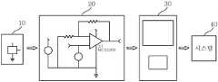
도2는 본 발명에 의한 엘이디 휘도 보상용 신호 연산 증폭회로를 구비한 엘이디 드라이버 기판의 전체구성을 도시하는 개략 블록도.Fig. 2 is a schematic block diagram showing the overall configuration of an LED driver substrate provided with an LED luminance compensation signal operational amplifier circuit according to the present invention.
도3은 본 발명에 의한 엘이디 휘도 보상용 신호 연산 증폭회로의 구성을 도시하는 상세 회로도.Fig. 3 is a detailed circuit diagram showing the structure of the signal luminance amplifier circuit for LED luminance compensation according to the present invention.
도4는 본 발명에 의한 엘이디 휘도 보상용 신호 연산 증폭회로를 채용했을 경우 센서 출력과 온도의 관계를 도시하는 그래프.Fig. 4 is a graph showing the relationship between sensor output and temperature when the signal luminance amplifier circuit for LED luminance compensation according to the present invention is adopted.
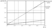
도5는 본 발명에 의한 엘이디 휘도 보상용 신호 연산 증폭회로에 종래 기술에 의한 일반적인 증폭기를 채용했을 경우와, 본 발명에 의한 레일-투-레일 연산 증폭기를 채용했을 경우에 따른 센서 출력과 온도의 관계를 도시하는 또 다른 그래프.Fig. 5 shows the sensor output and temperature of the LED luminance compensation signal operational amplifier circuit according to the present invention when the conventional amplifier according to the prior art and the rail-to-rail operational amplifier according to the present invention are adopted. Another graph showing the relationship.
< 도면의 주요 부호에 대한 설명 ><Description of Major Symbols in Drawing>
10: 온도센서10: temperature sensor
20: 레일-투-레일 연산 증폭기(rail-to-rail operational amplifier)20: rail-to-rail operational amplifier
30: 마이크로 컨트롤러30: microcontroller
40: 시스템40: system
본 발명은 LCD 패널용 엘이디 휘도 보상용 신호 증폭회로에 관한 것이다.The present invention relates to a signal amplification circuit for LED brightness compensation for LCD panels.
최근 LCD 패널의 백라이트 유닛의 광원용으로 전력효율이 높고, 광원제어가 용이한 엘이디를 주로 사용하고 있다.Recently, LEDs having high power efficiency and easy light source control are mainly used for light sources of backlight units of LCD panels.
백라이트 유닛용 광원으로 사용되는 RED(R), Green(G), Blue(B)의 엘이디 색(color)을 제어하는 기술이 개발되고 있다. 엘이디 드라이버의 백라이트용 광원으로 사용되는 엘이디의 배치 방법은 모듈(module), 블록(block) 또는 바(bar)별로 엘이디를 배열하여 고정한다. 최근 TFT LCD용 엘이디는 친환경적이고 색 재현율이 높은 방향으로 기술이 더욱 발전되고 있으며, 시장에서는 이러한 엘이디를 요구하고 있다. 엘이디는 고휘도와 폭 넓은 색 재현성 등의 많은 장점을 가지고 있다.A technology for controlling LED colors of RED (R), Green (G), and Blue (B) used as a light source for a backlight unit has been developed. In the method of arranging LEDs, which are used as LED light sources for backlighting, LEDs are arranged and fixed by modules, blocks, or bars. Recently, LEDs for TFT LCDs have been further developed in an environment-friendly and high color reproducibility direction, and the market demands such LEDs. LED has many advantages such as high brightness and wide color reproducibility.
하지만, 엘이디는 백라이트 유닛(Back Light Unit)용으로 부적합한 점들이 있다. 상기 부적함 중 하나가 온도에 따른 문제이다. 즉, 엘이디는 발광하면서 냉음극형광램프(CCFL) 보다 높은 온도를 발산한다. 상기와 같은 높은 온도로 인하여 엘이디의 휘도가 낮아지는 문제점이 있다. 따라서, 보다 선명한 엘이디 색상을 구현할 수 없는 문제가 있다.However, LEDs are inadequate for Back Light Units. One such deficiency is a problem with temperature. That is, the LED emits a higher temperature than the cold cathode fluorescent lamp (CCFL) while emitting light. Due to such a high temperature there is a problem that the brightness of the LED is lowered. Therefore, there is a problem that can not implement a brighter LED color.
상기와 같은 문제를 해결하고자, 온도 센서를 통하여 엘이디 온도를 측정하여 측정된 온도에 따른 전압을 마이크로 컨트롤러에 입력한다. 온도의 증가에 따라 낮아진 엘이디 휘도에 대하여, 마이크로 컨트롤러는 엘이디 드라이버에 엘이디의 전류를 조정하는 신호를 입력한다. 이에 따라 엘이디로 입력되는 전류는 증가함으로써 휘도가 조정된다.In order to solve the above problems, the LED temperature is measured through a temperature sensor and a voltage corresponding to the measured temperature is input to the microcontroller. For LED brightness lowered with increasing temperature, the microcontroller inputs a signal to the LED driver to adjust the LED's current. Accordingly, the luminance is adjusted by increasing the current input to the LED.
도1은 종래 기술에 의한 엘이디 휘도 보상용 온도 센서에서 센서 출력과 온도의 관계를 도시하는 그래프이다.1 is a graph showing the relationship between the sensor output and the temperature in the LED brightness compensation temperature sensor according to the prior art.
종래의 온도 센서는 입력단을 통하여 4V 내지 20V의 전압이 입력되고, 출력단을 통하여 온도 1도에 대하여 0mV 내지 10.0mV의 전압이 출력되어, LCD 패널의 전체 시스템(미도시)으로 입력된다.In the conventional temperature sensor, a voltage of 4V to 20V is input through an input terminal, and a voltage of 0mV to 10.0mV is output for 1 degree of temperature through an output terminal, and is input to an entire system (not shown) of the LCD panel.
상기와 같은 종래의 구성에 있어서, 온도가 1도 변할 때 출력 전압은 10mV가 변하도록 구성되기 때문에, 온도는 0~100도 범위에서 변하게 된다. 그리고, 그에 따른 온도 센서의 출력 전압은 0~1V의 범위로 변하게 된다.In the conventional configuration as described above, since the output voltage is configured to change 10 mV when the temperature changes by 1 degree, the temperature varies in the range of 0 to 100 degrees. Then, the output voltage of the temperature sensor accordingly is changed to a range of 0 ~ 1V.
도1에 도시된 바와 같이, 온도가 100도 일 때, 센서 출력은 1V가 된다. 상기와 같은 낮은 출력의 전원으로는 정전류 구동되는 마이크로 컨트롤러에서 엘이디 드라이버를 정상적으로 구동 못하는 관계로 엘이디의 출력의 출력 휘도가 현저히 떨어지는 문제가 있다.As shown in Fig. 1, when the temperature is 100 degrees, the sensor output becomes 1V. As the low output power as described above, the output brightness of the LED's output is significantly lowered because the LED driver is not normally driven in the constant current driven microcontroller.
상기와 같은 문제점을 극복하고자, 엘이디 휘도 보상회로 구성에서 일반적인 증폭기를 연결하여 낮은 출력의 전원을 증폭하여 내부 회로에서 필요로 하는 소정의 높이의 전원을 출력하고자 하였으나, 원하는 높이의 출력을 증폭할 수 없었다.In order to overcome the above problems, in the LED luminance compensation circuit configuration, a general amplifier is connected to amplify a low output power to output a predetermined height required by an internal circuit, but an output of a desired height can be amplified. There was no.
이와 같은 문제점들로 인하여, 엘이디는 고휘도성과 폭 넓은 색재현성을 가지고 있음에도 불구하고, 실제 적용에 있어 많은 어려움이 있어 왔다.Due to these problems, although LED has high brightness and wide color reproduction, there have been many difficulties in practical application.
본 발명은 온도센서부에서 검출된 신호를 소정의 크기로 증폭하여 마이크로 컨트롤러에 입력시킴으로써 LCD 패널의 엘이디 휘도를 효과적으로 보상할 수 있는 엘이디 휘도 보상용 신호 연산 증폭 회로를 제공하기 위한 것이다.The present invention is to provide a signal amplification circuit for LED brightness compensation that can effectively compensate for the LED brightness of the LCD panel by amplifying the signal detected by the temperature sensor unit to a predetermined size and input to the microcontroller.
본 발명은 엘이디를 채용한 LCD용 백라이트 유닛에서, 엘이디의 온도를 측정하여 출력하기 위한 온도센서와; 상기 온도센서로부터 출력된 온도에 따른 신호를 소정의 레벨로 증폭하여 정확한 디지털 레벨 신호를 출력하기 위한 레일-투-레일 연산 증폭기와; 상기 레일-투-레일 연산 증폭기로부터 출력된 증폭 신호를 입력받아 소정의 신호 보상을 실시하여 엘이디 온도 상승에 따라 엘이디의 휘도가 떨어지는 것을 방지하는 마이크로 컨트롤러를 포함한다.The present invention provides a backlight unit for LCD employing an LED, the temperature sensor for measuring and outputting the temperature of the LED; A rail-to-rail operational amplifier for amplifying a signal corresponding to the temperature output from the temperature sensor to a predetermined level and outputting an accurate digital level signal; And a microcontroller configured to receive an amplified signal output from the rail-to-rail operational amplifier and perform a predetermined signal compensation to prevent the luminance of the LED from falling as the LED temperature rises.
이하, 첨부된 도면에 근거하여 본 발명의 실시예를 상세히 설명한다.Hereinafter, embodiments of the present invention will be described in detail with reference to the accompanying drawings.
도2는 본 발명에 의한 엘이디 휘도 보상용 신호 연산 증폭회로를 구비한 엘 이디 드라이버 기판의 전체구성을 도시하는 블록도이다.Fig. 2 is a block diagram showing the overall configuration of the LED driver substrate including the LED luminance compensation signal operational amplifier circuit according to the present invention.
이에 도시된 바와 같이, 본 발명에 의한 엘이디 휘도 보상용 신호 증폭 회로는 온도센서(10)와, 상기 온도센서(10)와 연결되는 본 발명에 의한 레일-투-레일 연산 증폭기(20)와, 상기 레일-투-레일 연산 증폭기(20)와 연결된 마이크로 컨트롤러(30)와, 상기 마이크로 컨트롤러(30)와 연결된 시스템(40)으로 구성된다. 상기의 구성에서 온도센서(10)는 일반적인 온도센서로 구성되며, 그리고 바람직하게는 상기 본 발명에 의한 레일-투-레일 연산 증폭기(20)는 상기 온도센서(10)로부터 출력되는 온도 검출에 따라 소정의 선명도에 해당하는 신호를 출력할 수 있도록 구성된다.As shown in the drawing, the signal amplification circuit for LED luminance compensation according to the present invention includes a
그리고, 도3은 본 발명에 의한 엘이디 휘도 보상용 신호 연산 증폭회로에서 레일-투-레일 연산 증폭기(20)의 구성을 도시하는 회로도이다. 도3의 레일-투-레일 연산 증폭기(20)의 내부 작용을 설명하면 다음과 같다. 가장 일반적으로 사용되는 연산 증폭기(Op-amp)의 입력되는 전원과 비교하여 2~3V의 전압 드롭이 일어나지만 레일-투-레일 연산 증폭기는 입력이 1이면 출력이 1이 나오는 즉, 내부의 전압 손실(voltage loss) 없이 그대로 증폭시켜주는 특징을 갖는다. 이에 도시된 바와 같이, 상기 레일-투-레일 연산 증폭기(20)는 출력단자(21b)와 제1 입력단자(21C) 사이에는 저항(R1)이 연결되며, 제2 입력단자(21e)는 온도센서(10)와 연결되며, 전원전압(VCC)과 제1 입력단자(21c) 사이에는 저항(R2)이 연결되어 있다. 이에 따라, 레일-투-레일 연산 증폭기(20)는 제1 입력단자(21c)로 입력전압(Vcc)을 입력받고, 제2 입력단자(21e)로 온도센서의 측정온도를 입력받아 소정레벨로 증폭하여 출력단자(21b)로 출력 전압을 출력하되, 온도센서의 온도가 1도씨 변할 때, 레일-투-레일 연산 증폭기(20)의 출력 전압이 최소 5V 이상이 출력될 수 있다.3 is a circuit diagram showing the configuration of the rail-to-rail
상기와 같은 구성을 갖는 레일-투-레일 연산 증폭기(20)에서,In the rail-to-rail
Gain = (1+(R2/R1)) = 4.9이며,Gain = (1+ (R2 / R1)) = 4.9,
이에 따른 출력 온도 TH_Out = Temp_Sensor * GainResulting output temperature TH_Out = Temp_Sensor * Gain
이에 Gain 값을 대입하면,If you substitute a gain value,
TH_Out = Temp_Sensor * 4.9가 된다.TH_Out = Temp_Sensor * 4.9
즉, 본 발명에 의한 레일-투-레일 연산 증폭기(20)의 작동 결과가 도4에 도시되어 있다.That is, the operation result of the rail-to-rail
이에 도시된 바와 같기, 종래에는 온도센서(10)에서 1도가 변함에 따라, 출력 전압은 1V가 변하였으나, 본 발명에 의한 레일-투-레일 연산 증폭기(20)를 구성한 상태에서는 그 출력전압이 약 3.9배인 5V를 얻게 된다.As shown in the drawing, in the related art, as the temperature is changed by 1 degree in the
그리고, 도5는 본 발명에 의한 엘이디 휘도 보상용 신호 연산 증폭회로에 일반적인 연산 증폭기를 채용했을 경우와, 레일-투-레일 연산 증폭기를 채용했을 경우에 따른 센서 출력과 온도의 관계를 도시하는 또 다른 그래프이다.Fig. 5 shows the relationship between sensor output and temperature when a general operational amplifier is employed in the LED luminance compensation signal operational amplifier circuit according to the present invention and when a rail-to-rail operational amplifier is employed. Another graph.
이에 도시된 바와 같이, 일반적인 연산 증폭기를 채용했을 경우는 온도가 100도씨 일 때, 출력전압은 3.9.V였으며, 그리고 레일-투-레일 연산 증폭기를 채용했을 경우에는 온도가 100도씨 일 때, 출력전압은 4.9V였다. 따라서, 레일-투-레일 연산 증폭기를 채용했을 때가, 일반적인 연산 증폭기를 채용할 때와 비교하여 보다 높은 출력 전압을 얻을 수 있다.As shown here, when the temperature is 100 degrees Celsius, the output voltage is 3.9.V, and the temperature is 100 degrees Celsius when the rail-to-rail operational amplifier is adopted. , The output voltage was 4.9V. Therefore, when the rail-to-rail operational amplifier is adopted, a higher output voltage can be obtained compared with when employing a general operational amplifier.
본 발명은 기존의 엘이디 드라이버 기판에 온도센서부와, 레일-투-레일 연산 증폭기와, 마이크로 컨트롤러를 추가로 연결하여 온도센서부에서 검출된 신호를 소정의 크기로 증폭하여 마이크로 컨트롤라에 입력시킴으로써 LCD 패널의 엘이디 휘 도를 효과적으로 보상할 수 있다.According to the present invention, a temperature sensor unit, a rail-to-rail operational amplifier, and a microcontroller are additionally connected to an existing LED driver substrate to amplify a signal detected by the temperature sensor unit to a predetermined size and input the microcontroller. The LED brightness of the LCD panel can be effectively compensated.
본 발명은 온도센서로부터 출력되는 출력신호를 레일-투-레일 증폭기에서 수신하여 소정의 레벨로 증폭하여 보다 안정된 높이를 갖는 정확한 디지털 신호를 마이크로 컨트롤러에 입력함으로써 온도가 올라감에 따라 휘도가 떨어지는 종래의 엘이디 드라이버의 단점을 극복하여 재현성 높은 색을 구현할 수 있는 장점이 있다.The present invention receives the output signal output from the temperature sensor in the rail-to-rail amplifier and amplifies to a predetermined level to input a precise digital signal having a more stable height to the microcontroller, the luminance is lowered as the temperature rises. Overcoming the disadvantages of the LED driver has the advantage that can realize a high reproducible color.
Claims (4)
Translated fromKoreanPriority Applications (1)
| Application Number | Priority Date | Filing Date | Title |
|---|---|---|---|
| KR1020060041466AKR101228922B1 (en) | 2006-05-09 | 2006-05-09 | Signal operational amplification circuit for LED luminance compensation |
Applications Claiming Priority (1)
| Application Number | Priority Date | Filing Date | Title |
|---|---|---|---|
| KR1020060041466AKR101228922B1 (en) | 2006-05-09 | 2006-05-09 | Signal operational amplification circuit for LED luminance compensation |
Publications (2)
| Publication Number | Publication Date |
|---|---|
| KR20070109027A KR20070109027A (en) | 2007-11-15 |
| KR101228922B1true KR101228922B1 (en) | 2013-02-01 |
Family
ID=39063594
Family Applications (1)
| Application Number | Title | Priority Date | Filing Date |
|---|---|---|---|
| KR1020060041466AActiveKR101228922B1 (en) | 2006-05-09 | 2006-05-09 | Signal operational amplification circuit for LED luminance compensation |
Country Status (1)
| Country | Link |
|---|---|
| KR (1) | KR101228922B1 (en) |
Cited By (1)
| Publication number | Priority date | Publication date | Assignee | Title |
|---|---|---|---|---|
| US10460678B2 (en) | 2016-11-23 | 2019-10-29 | Samsung Display Co., Ltd. | Display device and method of driving the same |
Citations (4)
| Publication number | Priority date | Publication date | Assignee | Title |
|---|---|---|---|---|
| JP2002111120A (en)* | 2000-09-28 | 2002-04-12 | Toshiba Electronic Engineering Corp | Optical transmission module |
| US20020130786A1 (en)* | 2001-01-16 | 2002-09-19 | Visteon Global Technologies,Inc. | Series led backlight control circuit |
| JP3389653B2 (en) | 1993-10-22 | 2003-03-24 | 三菱化学株式会社 | Organic electroluminescent panel |
| KR20040085304A (en)* | 2003-03-31 | 2004-10-08 | 비오이 하이디스 테크놀로지 주식회사 | Drive device for LED backlight |
- 2006
- 2006-05-09KRKR1020060041466Apatent/KR101228922B1/enactiveActive
Patent Citations (4)
| Publication number | Priority date | Publication date | Assignee | Title |
|---|---|---|---|---|
| JP3389653B2 (en) | 1993-10-22 | 2003-03-24 | 三菱化学株式会社 | Organic electroluminescent panel |
| JP2002111120A (en)* | 2000-09-28 | 2002-04-12 | Toshiba Electronic Engineering Corp | Optical transmission module |
| US20020130786A1 (en)* | 2001-01-16 | 2002-09-19 | Visteon Global Technologies,Inc. | Series led backlight control circuit |
| KR20040085304A (en)* | 2003-03-31 | 2004-10-08 | 비오이 하이디스 테크놀로지 주식회사 | Drive device for LED backlight |
Cited By (1)
| Publication number | Priority date | Publication date | Assignee | Title |
|---|---|---|---|---|
| US10460678B2 (en) | 2016-11-23 | 2019-10-29 | Samsung Display Co., Ltd. | Display device and method of driving the same |
Also Published As
| Publication number | Publication date |
|---|---|
| KR20070109027A (en) | 2007-11-15 |
Similar Documents
| Publication | Publication Date | Title |
|---|---|---|
| JP4306657B2 (en) | Light emitting element driving device and display device | |
| KR101521099B1 (en) | A local dimming driving method, a light source device for performing the same, and a display device including the same | |
| KR100854192B1 (en) | Surface light source, luminance correction circuit, luminance correction method and liquid crystal display | |
| CN1937010A (en) | Light source unit for use in a lighting apparatus | |
| KR100968451B1 (en) | Display device and control method | |
| CN104913239B (en) | Planar illuminating device and liquid crystal display device | |
| CN103413529A (en) | Backlight system, liquid crystal display including the same, and method of adjusting backlight | |
| CN101427174A (en) | Lighting device for display device and control circuit thereof | |
| WO2011026269A1 (en) | Liquid crystal display with led backlight plate and attenuation detection method thereof | |
| KR20100062475A (en) | Method of drivin a light source, light-source apparatus for performing the method and display apparatus having the light-source apparatus | |
| WO2009135228A2 (en) | Methods and circuits for triode region detection | |
| KR101265102B1 (en) | Backlight unit and method of driving the same | |
| US8305336B2 (en) | Method of driving a light source, light source apparatus for performing the method and display apparatus having the light source apparatus | |
| US7825889B2 (en) | Field sequential mode liquid crystal display device and method of driving the same | |
| KR20090094143A (en) | Led module with dedicated colour regulation and corresponding method | |
| US9148928B2 (en) | Light emitting diode driver | |
| KR101228922B1 (en) | Signal operational amplification circuit for LED luminance compensation | |
| KR101511128B1 (en) | Method for driving light emitting diode, back light assembly for performing the method and display apparatus having the back light assembly | |
| CN101441856B (en) | Backlight module and method for controlling brightness of backlight module | |
| KR20100020214A (en) | Method of driving a light source, light source apparatus for performing the method and lquid crystal display device having the light source appratus | |
| JP2007317849A (en) | Backlight device and backlight control method | |
| KR102047732B1 (en) | Backlight unit | |
| KR20080032440A (en) | Backlight driving device and driving method thereof | |
| KR20090078525A (en) | LED backlight unit driver Current measuring device for current deviation compensation | |
| KR101607126B1 (en) | Back light unit |
Legal Events
| Date | Code | Title | Description |
|---|---|---|---|
| PA0109 | Patent application | Patent event code:PA01091R01D Comment text:Patent Application Patent event date:20060509 | |
| PG1501 | Laying open of application | ||
| A201 | Request for examination | ||
| PA0201 | Request for examination | Patent event code:PA02012R01D Patent event date:20110506 Comment text:Request for Examination of Application Patent event code:PA02011R01I Patent event date:20060509 Comment text:Patent Application | |
| PE0902 | Notice of grounds for rejection | Comment text:Notification of reason for refusal Patent event date:20120626 Patent event code:PE09021S01D | |
| E701 | Decision to grant or registration of patent right | ||
| PE0701 | Decision of registration | Patent event code:PE07011S01D Comment text:Decision to Grant Registration Patent event date:20121220 | |
| GRNT | Written decision to grant | ||
| PR0701 | Registration of establishment | Comment text:Registration of Establishment Patent event date:20130128 Patent event code:PR07011E01D | |
| PR1002 | Payment of registration fee | Payment date:20130129 End annual number:3 Start annual number:1 | |
| PG1601 | Publication of registration | ||
| FPAY | Annual fee payment | Payment date:20151204 Year of fee payment:4 | |
| PR1001 | Payment of annual fee | Payment date:20151204 Start annual number:4 End annual number:4 | |
| FPAY | Annual fee payment | Payment date:20161207 Year of fee payment:5 | |
| PR1001 | Payment of annual fee | Payment date:20161207 Start annual number:5 End annual number:5 | |
| FPAY | Annual fee payment | Payment date:20171205 Year of fee payment:6 | |
| PR1001 | Payment of annual fee | Payment date:20171205 Start annual number:6 End annual number:6 | |
| FPAY | Annual fee payment | Payment date:20181210 Year of fee payment:7 | |
| PR1001 | Payment of annual fee | Payment date:20181210 Start annual number:7 End annual number:7 | |
| FPAY | Annual fee payment | Payment date:20191209 Year of fee payment:8 | |
| PR1001 | Payment of annual fee | Payment date:20191209 Start annual number:8 End annual number:8 | |
| PR1001 | Payment of annual fee | Payment date:20201214 Start annual number:9 End annual number:9 | |
| PR1001 | Payment of annual fee | Payment date:20211213 Start annual number:10 End annual number:10 | |
| PR1001 | Payment of annual fee | Payment date:20221212 Start annual number:11 End annual number:11 | |
| PR1001 | Payment of annual fee | Payment date:20231212 Start annual number:12 End annual number:12 | |
| PR1001 | Payment of annual fee | Payment date:20241216 Start annual number:13 End annual number:13 |