KR101226066B1 - Liquid flow converging device and method of manufacturing multi-layer film - Google Patents
Liquid flow converging device and method of manufacturing multi-layer filmDownload PDFInfo
- Publication number
- KR101226066B1 KR101226066B1KR1020067023586AKR20067023586AKR101226066B1KR 101226066 B1KR101226066 B1KR 101226066B1KR 1020067023586 AKR1020067023586 AKR 1020067023586AKR 20067023586 AKR20067023586 AKR 20067023586AKR 101226066 B1KR101226066 B1KR 101226066B1
- Authority
- KR
- South Korea
- Prior art keywords
- liquid flow
- slit
- confluence
- liquid
- layered
- Prior art date
- Legal status (The legal status is an assumption and is not a legal conclusion. Google has not performed a legal analysis and makes no representation as to the accuracy of the status listed.)
- Expired - Lifetime
Links
Images


Classifications
- B—PERFORMING OPERATIONS; TRANSPORTING
- B29—WORKING OF PLASTICS; WORKING OF SUBSTANCES IN A PLASTIC STATE IN GENERAL
- B29C—SHAPING OR JOINING OF PLASTICS; SHAPING OF MATERIAL IN A PLASTIC STATE, NOT OTHERWISE PROVIDED FOR; AFTER-TREATMENT OF THE SHAPED PRODUCTS, e.g. REPAIRING
- B29C48/00—Extrusion moulding, i.e. expressing the moulding material through a die or nozzle which imparts the desired form; Apparatus therefor
- B29C48/16—Articles comprising two or more components, e.g. co-extruded layers
- B—PERFORMING OPERATIONS; TRANSPORTING
- B29—WORKING OF PLASTICS; WORKING OF SUBSTANCES IN A PLASTIC STATE IN GENERAL
- B29C—SHAPING OR JOINING OF PLASTICS; SHAPING OF MATERIAL IN A PLASTIC STATE, NOT OTHERWISE PROVIDED FOR; AFTER-TREATMENT OF THE SHAPED PRODUCTS, e.g. REPAIRING
- B29C48/00—Extrusion moulding, i.e. expressing the moulding material through a die or nozzle which imparts the desired form; Apparatus therefor
- B29C48/25—Component parts, details or accessories; Auxiliary operations
- B29C48/36—Means for plasticising or homogenising the moulding material or forcing it through the nozzle or die
- B29C48/50—Details of extruders
- B29C48/695—Flow dividers, e.g. breaker plates
- B29C48/70—Flow dividers, e.g. breaker plates comprising means for dividing, distributing and recombining melt flows
- B—PERFORMING OPERATIONS; TRANSPORTING
- B29—WORKING OF PLASTICS; WORKING OF SUBSTANCES IN A PLASTIC STATE IN GENERAL
- B29C—SHAPING OR JOINING OF PLASTICS; SHAPING OF MATERIAL IN A PLASTIC STATE, NOT OTHERWISE PROVIDED FOR; AFTER-TREATMENT OF THE SHAPED PRODUCTS, e.g. REPAIRING
- B29C48/00—Extrusion moulding, i.e. expressing the moulding material through a die or nozzle which imparts the desired form; Apparatus therefor
- B29C48/03—Extrusion moulding, i.e. expressing the moulding material through a die or nozzle which imparts the desired form; Apparatus therefor characterised by the shape of the extruded material at extrusion
- B29C48/07—Flat, e.g. panels
- B29C48/08—Flat, e.g. panels flexible, e.g. films
- B—PERFORMING OPERATIONS; TRANSPORTING
- B29—WORKING OF PLASTICS; WORKING OF SUBSTANCES IN A PLASTIC STATE IN GENERAL
- B29C—SHAPING OR JOINING OF PLASTICS; SHAPING OF MATERIAL IN A PLASTIC STATE, NOT OTHERWISE PROVIDED FOR; AFTER-TREATMENT OF THE SHAPED PRODUCTS, e.g. REPAIRING
- B29C48/00—Extrusion moulding, i.e. expressing the moulding material through a die or nozzle which imparts the desired form; Apparatus therefor
- B29C48/16—Articles comprising two or more components, e.g. co-extruded layers
- B29C48/18—Articles comprising two or more components, e.g. co-extruded layers the components being layers
- B29C48/21—Articles comprising two or more components, e.g. co-extruded layers the components being layers the layers being joined at their surfaces
- B—PERFORMING OPERATIONS; TRANSPORTING
- B29—WORKING OF PLASTICS; WORKING OF SUBSTANCES IN A PLASTIC STATE IN GENERAL
- B29C—SHAPING OR JOINING OF PLASTICS; SHAPING OF MATERIAL IN A PLASTIC STATE, NOT OTHERWISE PROVIDED FOR; AFTER-TREATMENT OF THE SHAPED PRODUCTS, e.g. REPAIRING
- B29C48/00—Extrusion moulding, i.e. expressing the moulding material through a die or nozzle which imparts the desired form; Apparatus therefor
- B29C48/25—Component parts, details or accessories; Auxiliary operations
- B29C48/30—Extrusion nozzles or dies
- B29C48/305—Extrusion nozzles or dies having a wide opening, e.g. for forming sheets
- B29C48/307—Extrusion nozzles or dies having a wide opening, e.g. for forming sheets specially adapted for bringing together components, e.g. melts within the die
Landscapes
- Engineering & Computer Science (AREA)
- Mechanical Engineering (AREA)
- Manufacturing & Machinery (AREA)
- Physical Or Chemical Processes And Apparatus (AREA)
- Extrusion Moulding Of Plastics Or The Like (AREA)
Abstract
Translated fromKoreanDescription
Translated fromKorean본 발명은 적어도 2개의 액체흐름을 층형상으로 합류시키고, 각 액체흐름이 층형상으로 배열되어서 이루어지는 층형상의 액체흐름을 형성하기 위한 액체흐름의 합류장치, 및 그것을 사용한 다층 필름의 제조방법에 관한 것이다. 더욱 상세하게는, 서로 특성이 다른 2종류이상의 액체흐름을 층형상으로 합류시키고, 다른 액체흐름이 층형상으로 합류해서 형성되는 다계면을 갖는 층형상의 액체흐름을 형성하기 위한 액체흐름의 합류장치에 관한 것이다.The present invention relates to a confluence apparatus for a liquid flow for forming a layered liquid flow in which at least two liquid flows are joined in a layered form and each liquid flow is arranged in a layered form, and a method for producing a multilayer film using the same. will be. More specifically, two or more types of liquid flows having different characteristics from each other are joined in a layered form, and a liquid flow confluence apparatus for forming a multi-layered layered liquid flow formed by joining different liquid flows in a layered form. It is about.
다수의 액체흐름을 합류시켜 다층의 액체흐름을 형성하는 장치는, 다층구조를 갖는 필름을 효율적으로 제조하는 수단으로서 이용되고 있다.An apparatus for forming a plurality of liquid flows by joining a plurality of liquid flows is used as a means for efficiently producing a film having a multilayer structure.
구체적인 예로서, 다층공압출 피드 블록이 알려져 있다(후술의 특허문헌1 내지 3을 참조). 또, 경계면 형성장치(ISG:Interfacial Surface Generator)라고도 불리는 소위 스퀘어 믹서도 알려져 있다(후술의 특허문헌4 및 5를 참조).As a specific example, a multilayer coextrusion feed block is known (see
그러나 특허문헌1 내지 3에 제안되어 있는 장치의 경우, 실용상 전체 층수가 300이하인 다층 필름을 얻는 것이 한도이다. 그 이상의 층수를 갖는 다층 필름의 제조에 이 종래의 장치를 사용할 경우, 장치가 일방향으로 대형화된다. 그 때문에 장치 내에 액체의 체류부분이 생기게 된다. 장치 내에 체류된 액체는 열열화를 받아 이물의 발생을 초래한다. 극단적인 경우에는 액체가 장치 내를 균일하게 흐르지 않는 현상이 생긴다.However, in the case of the apparatus proposed by patent documents 1-3, it is a limit to obtain the multilayer film whose total layer number is 300 or less practically. When using this conventional apparatus for the manufacture of a multilayer film having a larger number of layers, the apparatus is enlarged in one direction. This results in a retention portion of the liquid in the device. The liquid retained in the device undergoes thermal degradation resulting in the generation of foreign bodies. In extreme cases, liquid does not flow evenly through the device.
특허문헌4 및 5에 제안되어 있는 장치의 경우, 다층공압출 피드 블록과 스퀘어 믹서를 조합함으로써 효율적으로 층수를 증가시킬 수 있다. 그러나 광학간섭 필름이나 굴절율제어 필름 등의 매우 높은 적층정밀도를 필요로 하는 다층 필름을 제조할 때에는, 믹서 내에서의 액체흐름의 유로변형에 기인하여 층변형이 발생한다. 그 때문에 높은 적층정밀도를 유지하기 위해서는 700층이하의 층수가 한계였다. 또, 굴절율제어 필름 등에서 요구되는 복잡한 층두께 구성을 갖는 다층 필름을 제조하는 것은 이들 종래의 방법 혹은 장치에서는 불가능했다.In the case of the devices proposed in
[특허문헌1:미국특허 3884606호 공보][Patent Document 1: US Patent No. 3884606]
[특허문헌2:미국특허 3687589호 공보][Patent Document 2: US Patent 3687589]
[특허문헌3:일본 특허공개 2003-112355호 공보(제2페이지)][Patent Document 3: Japanese Patent Publication No. 2003-112355 (Page 2)]
[특허문헌4:미국특허 3565985호 공보][Patent Document 4: US Patent 3565985]
[특허문헌5:일본특허 3264958호 공보(제2페이지)][Patent Document 5: Japanese Patent No. 3264958 (Second Page)]
본 발명에 의해 이러한 종래기술의 문제가 해결되어 장치가 대형화되는 일이 없고, 이물의 발생은 거의 없으며, 매우 높은 적층정밀도를 갖고, 700층이상의 다층구조의 다층 필름을 임의의 층구성으로 효율적으로 얻을 수 있는 액체흐름의 합류장치가 제공된다. 본 발명에 따른 액체흐름의 합류장치는 광대역의 간섭반사 필름이나 굴절율제어 필름이나 층두께가 나노 오더로 되는 다층 필름의 제조에 바람직하게 사용된다. The present invention solves this problem of the prior art, and the apparatus is not large, there is little foreign matter, very high lamination accuracy, and a multilayer film having a multilayer structure of 700 layers or more in an arbitrary layer structure efficiently. A confluence device of obtainable liquid flow is provided. The confluence device of the liquid flow according to the present invention is preferably used for the production of a broadband interference reflection film, a refractive index control film or a multilayer film whose layer thickness is nano order.
본 발명의 액체흐름의 합류장치는 적어도 2개의 액체흐름을 층형상으로 합류시키는 액체흐름의 합류장치로서,The confluence device of the liquid flow of the present invention is a confluence device of the liquid flow for joining at least two liquid flows in a layered form,
(a)상기 각 액체흐름의 각각이 통과하는 다수의 슬릿이 형성된 요소A와,(a) an element A having a plurality of slits through which each of the liquid flows passes,
(b)상기 각 액체흐름이 상기 다수의 슬릿을 통과함으로써 형성되는 다수의 층형상의 액체흐름이 소정의 순서로 층형상으로 합류하여, 제1의 층형상 액체흐름을 형성하는 제1의 합류부가 형성된 요소B를 갖고,(b) a first confluence unit for forming a first layered liquid flow by joining the plurality of layered liquid flows formed by passing each of the liquid streams through the plurality of slits in a predetermined order to form a first layered liquid flow. With element B formed,
(c)상기 요소A가 각각 독립적으로 2개이상 존재하고, 또 상기 요소B가 각각 독립적으로 2개이상 존재하며,(c) two or more elements A are each independently, and two or more elements B are each independently,
(d)상기 액체흐름의 합류장치에 공급되는 상기 각 액체흐름을 수용하여, 상기 각 요소A에 상기 각 액체흐름을 공급하는 액체저장부가 형성된 요소C를 갖고, 또한,(d) an element C in which a liquid storage portion for receiving the respective liquid flows supplied to the confluence device of the liquid flows and supplying the respective liquid flows to each of the elements A is formed;
(e)상기 각 요소B에서 형성된 상기 각 제1의 층형상 액체흐름이 소정의 순서로 층형상으로 합류되어, 제2의 층형상 액체흐름을 형성하는 제2의 합류부가 형성된 요소D를 갖고 이루어진다.(e) each of the first layered liquid flows formed in each element B is joined in a layered order in a predetermined order, and has an element D having a second confluence formed therein to form a second layered liquid flow. .
본 발명의 액체흐름의 합류장치에 있어서, 상기 요소A에 형성된 슬릿의 수가 10이상 400이하인 것이 바람직하다.In the confluence apparatus of the liquid flow of the present invention, it is preferable that the number of slits formed in the element A is 10 or more and 400 or less.
본 발명의 액체흐름의 합류장치에 있어서, 상기 요소A에 형성된 각 슬릿의 간극이 10㎛이상 30,000㎛이하인 것이 바람직하다.In the confluence apparatus of the liquid flow of the present invention, it is preferable that the gap of each slit formed in the element A is 10 µm or more and 30,000 µm or less.
본 발명의 액체흐름의 합류장치에 있어서, 상기 요소C가 3개이상 존재하고, 같은 종류의 상기 액체흐름을 2개이상의 상기 요소C에 공급하기 위한 유로분할부가 상기 동일한 종류의 액체흐름의 공급원과 상기 각 요소C 사이에 형성되어 있는 것이 바람직하다.In the confluence apparatus of the liquid flow of the present invention, three or more of the elements C are present, and a flow path dividing unit for supplying the same kind of liquid flows to the two or more elements C contains a source of the same type of liquid flow. It is preferable to form between each said element C.
본 발명의 액체흐름의 합류장치에 있어서, 상기 요소A와 상기 요소B의 쌍 중 적어도 2개쌍에 있어서, 상기 요소B에 의해 형성되는 상기 제1의 층형상 액체흐름에 있어서의 상기 각 액체흐름의 계면이 서로 평행해지도록 상기 쌍이 배치되어 있는 것이 바람직하다.In the confluence apparatus of the liquid flow of the present invention, in each of the liquid flows in the first layered liquid flow formed by the element B in at least two pairs of the element A and the element B pairs. The pair is preferably arranged such that the interfaces are parallel to each other.
본 발명의 액체흐름의 합류장치에 있어서, 인접하는 상기 요소A의 사이에 상기 요소C가 배치되어 있는 것이 바람직하다.In the confluence apparatus of the liquid flow of the present invention, it is preferable that the element C is disposed between the adjacent element A.
본 발명의 액체흐름의 합류장치의 일형태에 있어서, 상기 요소C로부터 상기 요소A에 형성된 각 슬릿으로 상기 액체흐름을 공급하는 유로가 미세한 구멍으로 형성되어 있다.In one embodiment of the confluence apparatus of the liquid flow of the present invention, a flow path for supplying the liquid flow from the element C to each slit formed in the element A is formed with a fine hole.
본 발명의 액체흐름의 합류장치의 일형태에 있어서, 상기 요소A에 형성된 각 슬릿에 있어서 액체 공급면측과 액체 비공급면측의 슬릿의 종단면적이 서로 다르다.In one embodiment of the confluence apparatus of the liquid flow of the present invention, in each slit formed in the element A, the longitudinal cross-sectional areas of the slits on the liquid supply surface side and the liquid non-supply surface side are different from each other.
본 발명의 액체흐름의 합류장치에 있어서, 상기 요소A에 형성된 각 슬릿의 폭이 10㎜이상 200㎜이하인 것이 바람직하다.In the confluence apparatus of the liquid flow of the present invention, it is preferable that the width of each slit formed in the element A is 10 mm or more and 200 mm or less.
본 발명의 액체흐름의 합류장치에 있어서, 상기 요소A에 형성된 각 슬릿의 길이가 20㎜이상 200㎜이하인 것이 바람직하다.In the confluence device of the liquid flow of the present invention, it is preferable that the length of each slit formed in the element A is 20 mm or more and 200 mm or less.
본 발명의 액체흐름의 합류장치의 일형태에 있어서, 상기 요소A에 형성된 각 슬릿의 형상이 단계적으로 변화되는 부위를 포함하고 있다.In one embodiment of the confluence apparatus of the liquid flow of the present invention, the shape of each slit formed in the element A includes a portion where the shape of the slit changes in stages.
본 발명의 액체흐름의 합류장치의 일형태에 있어서, 상기 요소B로부터 상기 요소D로 이르는 상기 제1의 층형상 액체흐름의 유로단면형상이 사각이다.In one embodiment of the confluence apparatus of the liquid flow of the present invention, the flow path cross-sectional shape of the first layered liquid flow from the element B to the element D is square.
본 발명의 액체흐름의 합류장치의 상기 일형태에 있어서의 상기 사각의 모서리의 반경(R)이 10㎛이상 1㎜이하인 것이 바람직하다.It is preferable that the radius R of the said corner | corner of the said square in the said one aspect of the liquid flow confluence apparatus of this invention is 10 micrometers or more and 1 mm or less.
본 발명의 다층 필름의 제조방법은 적어도 2개의 액체흐름이 상기 본 발명의 액체흐름의 합류장치에 공급되고, 상기 액체흐름의 합류장치에 의해 상기 각 액체흐름이 층형상으로 배열되어서 이루어지는 층형상 액체흐름이 형성되며, 형성된 층형상 액체흐름으로부터 다층 필름이 형성되는 것으로 이루어진다.In the method for producing a multilayer film of the present invention, a layered liquid in which at least two liquid flows are supplied to the confluence device of the liquid flow of the present invention, and the liquid flows are arranged in a layered manner by the confluence device of the liquid flow. A flow is formed, consisting of the formation of a multilayer film from the formed layered liquid flow.
본 발명의 실시에 있어서 사용되는 액체흐름으로서는 다음에 설명하는 재료로 형성되는 액체흐름이 바람직하게 사용된다.As the liquid flow used in the practice of the present invention, a liquid flow formed of the material described below is preferably used.
재료의 하나로서 열가소성 수지가 있다. 열가소성 수지로서는, 예를 들면 폴리에틸렌, 폴리프로필렌, 폴리스티렌, 폴리메틸펜텐 등의 폴리올레핀 수지, 지환족 폴리올레핀 수지, 나일론6, 나일론66 등의 폴리아미드 수지, 아라미드 수지, 폴리에틸렌테레프탈레이트, 폴리부틸렌테레프탈레이트, 폴리프로필렌테레프탈레이트, 폴리부틸석시네이트, 폴리에틸렌-2,6-나프탈레이트 등의 폴리에스테르 수지, 폴리카보네이트 수지, 폴리아릴레이트 수지, 폴리아세탈 수지, 폴리페닐렌설파이드 수지, 4불화 에틸렌 수지, 3불화 에틸렌 수지, 3불화 염화에틸렌 수지, 4불화 에틸렌-6불화 프로필렌 공중합체, 불화 비닐리덴 수지 등의 불소 수지, 아크릴 수지, 메타크릴 수지, 폴리아세탈 수지, 폴리글리콜산 수지, 폴리유산 수지가 있다. 이들 열가소성 수지는 호모 수지여도 되고, 공중합 또는 2종류이상의 블렌드여도 된다. 열가소성 수지 중에는 각종 첨가제, 예를 들면 산화방지제, 대전방지제, 결정핵제, 무기입자, 유기입자, 점도환원제, 열안정제, 윤활제, 적외선흡수제, 자외선흡수제, 굴절율조정을 위한 도프제 등이 첨가되어 있어도 된다.One of the materials is a thermoplastic resin. As the thermoplastic resin, for example, polyolefin resin such as polyethylene, polypropylene, polystyrene, polymethylpentene, alicyclic polyolefin resin, polyamide resin such as
열가소성 수지는 폴리에스테르인 것이 보다 바람직하다. 폴리에스테르는 일반적으로 다른 열가소성 수지에 비교해서 분자량이 낮고, 또한 최적의 점도의 선택이 용이하므로, 본 발명의 액체흐름의 합류장치를 사용함으로써 효율적으로 700이상의 층수를 갖는 층형상 액체흐름을 용이하게 형성할 수 있기 때문이다.As for a thermoplastic resin, it is more preferable that it is polyester. Polyesters generally have a lower molecular weight compared to other thermoplastic resins, and the optimum viscosity can be easily selected. Therefore, by using the confluence device of the liquid flow of the present invention, the layered liquid flow having a layer number of 700 or more can be easily carried out. It can form.
폴리에스테르로서는 디카르복실산 골격성분과 디올 골격성분의 중축합체인 호모 폴리에스테르나 공중합 폴리에스테르가 있다.Examples of the polyester include homopolyesters and copolyesters which are polycondensates of a dicarboxylic acid skeleton component and a diol skeleton component.
호모 폴리에스테르로서는, 예를 들면 폴리에틸렌테레프탈레이트, 폴리프로필렌테레프탈레이트, 폴리부틸렌테레프탈레이트, 폴리에틸렌-2,6-나프탈레이트, 폴리-1,4-시클로헥산디메틸렌테레프탈레이트, 폴리에틸렌디페닐레이트가 있다. 특히 폴리에틸렌테레프탈레이트는 저렴하므로 매우 다방면에 걸친 용도로 사용할 수 있어 바람직하다.Examples of the homo polyester include polyethylene terephthalate, polypropylene terephthalate, polybutylene terephthalate, polyethylene-2,6-naphthalate, poly-1,4-cyclohexanedimethylene terephthalate, and polyethylene diphenylate. have. In particular, polyethylene terephthalate is preferable because it can be used for a very wide range of uses because it is inexpensive.
공중합 폴리에스테르로서는 다음에 예시하는 디카르복실산 골격성분과 디올 골격성분로부터 선택되는 적어도 3개이상의 성분으로 이루어지는 중축합체가 있다. 디카르복실산 골격성분으로서는 테레프탈산, 이소프탈산, 프탈산, 1,4-나프탈렌디카르복실산, 1,5-나프탈렌디카르복실산, 2,6-나프탈렌디카르복실산, 4,4'-디페닐디카르복실산, 4,4'-디페닐술폰디카르복실산, 아디핀산, 세바신산, 다이머산, 시클로헥산디카르복실산과 그들의 에스테르 유도체 등이 예시된다. 글리콜 골격성분으로서는 에틸렌글리콜, 1,2-프로판디올, 1,3-부탄디올, 1,4-부탄디올, 1,5-펜타디올, 디에틸렌글리콜, 폴리알킬렌글리콜, 2,2-비스(4'-β-히드록시에톡시페닐)프로판, 이소소르베이트, 1,4-시클로헥산디메탄올 등이 예시된다.As copolyester, there exists a polycondensate which consists of at least 3 or more components chosen from the dicarboxylic acid skeleton component and diol skeleton component which are illustrated next. As the dicarboxylic acid skeleton component, terephthalic acid, isophthalic acid, phthalic acid, 1,4-naphthalenedicarboxylic acid, 1,5-naphthalenedicarboxylic acid, 2,6-naphthalenedicarboxylic acid, 4,4'-di Phenyl dicarboxylic acid, 4,4'- diphenyl sulfone dicarboxylic acid, adipic acid, sebacic acid, dimer acid, cyclohexanedicarboxylic acid, ester derivatives thereof, etc. are illustrated. As the glycol skeleton component, ethylene glycol, 1,2-propanediol, 1,3-butanediol, 1,4-butanediol, 1,5-pentadiol, diethylene glycol, polyalkylene glycol, 2,2-bis (4 ' -beta -hydroxyethoxyphenyl) propane, isosorbate, 1,4-cyclohexanedimethanol and the like are exemplified.
본 발명의 실시에 있어서 사용되는 액체흐름을 형성하는 다른 재료의 예로서는, 각종 유기용매나 물 등의 저분자 화합물, 수지와 유기용매나, 모노머와 유기용매, 수지와 물, 모노머와 물 등의 2종류이상의 조성물로 이루어지는 혼합물 등이 있다. 또 액체흐름의 상태로서는 통상의 액체나 용융유체 외, 초임계유체, 액정 등이 포함된다. 또한, 고형물이 분산된 액체, 기포가 분산된 액체 등도 포함된다.Examples of other materials forming the liquid flow used in the practice of the present invention include two kinds of low molecular weight compounds such as various organic solvents and water, resins and organic solvents, monomers and organic solvents, resins and water, monomers and water. And mixtures composed of the above compositions. In addition, the liquid flow may include a supercritical fluid, a liquid crystal, or the like, in addition to the usual liquid or molten fluid. Also included are liquids in which solids are dispersed and liquids in which bubbles are dispersed.
본 발명의 액체흐름의 합류장치에 있어서 사용되는 합류란, 각각의 유로로부터 공급된 액체흐름을 하나의 유로에 공급하는 것을 말한다. 따라서, 합류되는 적어도 2개의 액체흐름은 서로 다른 특성을 갖는 액체흐름이여도 되고, 서로 동일한 특성을 갖는 액체흐름이여도 된다. 어떤 하나의 공급원으로부터 공급된 액체흐름을, 일단 복수의 액체흐름으로 분할한 후, 다시 본 발명의 액체흐름의 합류장치에서 합류시켜도 된다.The confluence used in the confluence device of the liquid flow of the present invention means supplying the liquid flow supplied from each flow path to one flow path. Therefore, the at least two liquid flows joined may be liquid flows having different characteristics, or liquid flows having the same characteristics as each other. The liquid flow supplied from any one source may be divided once into a plurality of liquid flows and then joined again in the confluence device of the liquid flow of the present invention.
<발명의 효과>EFFECTS OF THE INVENTION [
본 발명의 액체흐름을 층형상으로 합류시키는 액체흐름의 합류장치는 적어도 2개의 액체흐름의 각각이 통과하는 다수의 슬릿이 형성된 요소A와, 각 액체흐름이 다수의 슬릿을 통과함으로써 형성되는 다수의 층형상의 액체흐름이 층형상으로 합류하여, 제1의 층형상 액체흐름을 형성하는 제1의 합류부가 형성된 요소B를 갖고, 또한 이 합류장치에는 상기 요소A가 독립적으로 2개이상 구비되고, 상기 요소B가 독립적으로 2개이상 구비되며, 상기 각 요소A에 상기 각 액체흐름을 공급하는 액체저장부가 형성된 요소C가 구비되고, 또한 상기 각 요소B에서 형성된 상기 각 제1의 층형상 액체흐름이 층형상으로 합류하여 제2의 층형상 액체흐름을 형성하는 제2의 합류부가 형성된 요소D가 구비되어 있다. 그 결과, 본 발명의 액체흐름의 합류장치는 장치가 대형화되지 않고, 장치 내에 있어서의 이물의 발생은 거의 없는 상태에 있어서, 매우 높은 적층정밀도를 갖는 다층 액체흐름의 형성을 가능하게 하고, 700이상의 층을 갖는 다층 필름의 제조용의 다층 액체흐름의 형성을 가능하게 한다. 또, 매우 많은 층수에 있어서도 각 층의 두께를 자유롭게 제어할 수 있게 한다.The liquid flow confluence device for consolidating the liquid flow of the present invention in the form of a layer includes a plurality of elements A formed with a plurality of slits through which each of the at least two liquid flows passes, and a plurality of liquid flows formed by passing through the plurality of slits. The layered liquid flows merge in a layered manner, and has an element B having a first confluence formed therein to form a first layered liquid flow. The confluence apparatus is provided with two or more elements A independently, At least two elements B are provided independently, and each element A is provided with an element C having a liquid storage portion for supplying the respective liquid flows, and each of the first layered liquid flows formed at each element B. The element D is provided with a second confluence which joins the layered form and forms the second layered liquid flow. As a result, the confluence device of the liquid flow of the present invention enables the formation of a multilayer liquid flow having a very high lamination accuracy in a state where the apparatus is not enlarged and there is little generation of foreign matter in the apparatus. It is possible to form a multilayer liquid flow for the production of multilayer films with layers. In addition, even in a very large number of layers, the thickness of each layer can be freely controlled.
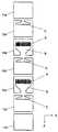
도 1은, 본 발명의 합류장치의 일실시예의 개략측면도이다.1 is a schematic side view of an embodiment of the joining apparatus of the present invention.
도 2는, 도 1에 나타낸 장치의 정면도이다.FIG. 2 is a front view of the apparatus shown in FIG. 1.
도 3은, 본 발명의 합류장치에 있어서 사용되는 제1의 합류 형성장치의 일형태의 각 부품을 분해하고, 순차적으로 전개해서 나타내는 정면도이다.Fig. 3 is a front view showing the parts of one embodiment of the first confluence forming device used in the confluence device of the present invention, disassembled, expanded and shown in sequence.
도 4는, 도 3에 있어서의 액체도입판의 일형태의 정면도이다.FIG. 4 is a front view of one embodiment of the liquid introduction plate in FIG. 3.
도 5는, 도 4에 있어서의 S1-S1 화살표방향에서 본 단면도이다.FIG. 5 is a sectional view seen from the arrow direction S1-S1 in FIG. 4. FIG.
도 6은, 도 3에 있어서의 슬릿판의 일형태의 정면도이다.FIG. 6 is a front view of one embodiment of the slit plate in FIG. 3.
도 7은, 도 6에 있어서의 S2-S2 화살표방향에서 본 단면도이다.FIG. 7 is a sectional view seen from the arrow direction S2-S2 in FIG. 6.
도 8은, 도 6에 있어서의 S3-S3 화살표방향에서 본 단면도이다.FIG. 8 is a sectional view seen from the arrow direction S3-S3 in FIG. 6.
도 9는, 도 3에 있어서의 슬릿판과 그 양 옆에 위치하는 액체도입판을 조립한 상태에 있어서의 도 6에 나타내는 S2-S2 화살표방향에서 본 단면도이다.FIG. 9 is a sectional view seen from the arrow direction S2-S2 shown in FIG. 6 in a state in which the slit plate in FIG. 3 and the liquid introduction plates positioned on both sides thereof are assembled.
도 10은, 도 3에 있어서의 슬릿판과 그 양 옆에 위치하는 액체도입판을 조립한 상태에 있어서의 도 6에 나타내는 S3-S3 화살표방향에서 본 단면도이다.FIG. 10 is a sectional view seen from the arrow direction S3-S3 shown in FIG. 6 in a state in which the slit plate in FIG. 3 and the liquid introduction plates positioned on both sides thereof are assembled.
도 11은, 도 3에 나타낸 제1의 합류 형성장치가 구비된 합류장치에 있어서 사용되는 제2의 합류 형성장치의 일형태의 정면 개략모식도이다.FIG. 11 is a schematic front view of one embodiment of a second confluence forming apparatus used in the confluence apparatus provided with the first confluence forming apparatus shown in FIG. 3.
도 12는, 도 11에 있어서의 S4-S4, S5-S5, S6-S6, 및 S7-S7 화살표방향에서 본 단면도이다. 이들 단면도는 순차 (a), (b), (c), 및 (d)로 나타내어져 있다.FIG. 12 is a sectional view seen from the arrow directions S4-S4, S5-S5, S6-S6, and S7-S7 in FIG. These cross-sectional views are shown by (a), (b), (c), and (d) sequentially.
도 13은, 본 발명의 합류장치에 있어서 사용되는 제1의 합류 형성장치의 다른 형태의 각 부품을 분해하고, 순차 전개해서 나타내는 정면도이다.FIG. 13: is a front view which decomposes | disassembles, expands and shows each component of the other aspect of the 1st confluence formation apparatus used in the confluence apparatus of this invention.
도 14는, 도 13에 나타낸 제1의 합류 형성장치가 구비된 합류장치에 있어서 사용되는 제2의 합류 형성장치의 일형태의 정면 개략모식도이다.FIG. 14 is a schematic front view of one embodiment of a second confluence forming apparatus used in the confluence apparatus equipped with the first confluence forming apparatus shown in FIG. 13.
도 15는, 도 14에 있어서의 S8-S8, S9-S9, S10-S10, 및 S11-S11 화살표방향에서 본 단면도이다. 이들 단면도는 순차 (a), (b), (c), 및 (d)로 나타내어져 있다.FIG. 15 is a sectional view seen from the arrow directions S8-S8, S9-S9, S10-S10, and S11-S11 in FIG. These cross-sectional views are shown by (a), (b), (c), and (d) sequentially.
도 16은, 본 발명의 합류장치에 있어서 사용되는 제1의 합류 형성장치의 또 다른 형태의 각 부품을 분해하고, 순차 전개해서 나타내는 정면도이다.Fig. 16 is a front view showing the parts of another embodiment of the first confluence forming apparatus used in the confluence device of the present invention, disassembled, expanded and shown in sequence.
도 17은, 본 발명의 합류장치에 있어서 사용되는 제2의 합류 형성장치의 또 다른 형태의 정면 개략모식도이다.Fig. 17 is a schematic front view of still another embodiment of a second confluence forming device used in the confluence device of the present invention.
도 18은, 도 17에 있어서의 S12-S12, S13-S13, 및 S14-S14 화살표방향에서 본 단면도이다. 이들 단면도는 순차 (a), (b), 및 (c)로 나타내어져 있다.FIG. 18 is a sectional view seen from the arrow directions S12-S12, S13-S13, and S14-S14 in FIG. These cross-sectional views are shown by (a), (b), and (c) sequentially.
도 19는, 본 발명의 합류장치를 이용하여 제조된 다층 필름의 일례의 반사율의 측정결과를 나타내는 그래프이다.19 is a graph showing a measurement result of reflectance of one example of a multilayer film produced using the joining apparatus of the present invention.
<도면의 주요부분에 대한 부호의 설명><Description of the symbols for the main parts of the drawings>
1:액체흐름의 합류장치 2:액체흐름 공급장치1: confluence device for liquid flow 2: liquid flow supply device
3:제1의 합류 형성장치 4:제2의 합류 형성장치3: first confluence forming apparatus 4: second confluence forming apparatus
12:액체흐름 도입판 13:슬릿판12: Liquid flow introduction plate 13: Slit plate
21:액체흐름 도입개구 22:액체저장부21: liquid flow opening opening 22: liquid storage
31:슬릿격벽 32:슬릿31: Slit bulkhead 32: Slit
33:슬릿부 51:층형상 액체흐름33: slit part 51: layered liquid flow
61:제1의 합류부 62:제1의 합류부 출구61: first confluence 62: first confluence exit
81:제1의 층형상 액체흐름 82:제2의 층형상 액체흐름81: first layered liquid flow 82: second layered liquid flow
83:합성 층형상 액체흐름 84:제2의 합류부83: synthetic layered liquid flow 84: second confluence
121a, 121b:구멍121a, 121b: hole
A:요소A B:요소BA: Element A B: Element B
C:요소C D:요소DC: Element C D: Element D
이하에 있어서, 본 발명의 액체흐름의 합류장치의 실시형태를 도면을 참조하면서 설명한다.EMBODIMENT OF THE INVENTION Below, embodiment of the confluence apparatus of the liquid flow of this invention is described, referring drawings.
본 발명의 액체흐름의 합류장치의 1실시형태가 도 1 내지 도 3에 나타내어진 다. 본 발명의 액체흐름의 합류장치(1)는 액체흐름 공급장치(2), 제1의 합류 형성장치(3), 및 제2의 합류 형성장치(4)로 이루어진다. 도 3에 제1의 합류 형성장치(3)를 분해하고, 각 부품을 순차 전개한 상태가 나타내어진다.One embodiment of the confluence apparatus of the liquid flow of the present invention is shown in Figs. The
제1의 합류 형성장치(3)는 양단에 끝판(11a, 11b)을 갖는다. 이 형태에 있어서는 끝판(11a)과 끝판(11b)은 경면 대칭으로 같은 구조를 갖고 있다. 이하에 있어서, 끝판(11a) 및 끝판(11b)을 끝판(11)으로 총칭하는 경우가 있다.The first
제1의 합류 형성장치(3)에 있어서, 끝판(11a)과 끝판(11b) 사이에 제1판(12a), 제2판(13a), 제3판(12b), 제4판(13b), 및 제5판(12c)이 이 순서로 끝판(11a)으로부터 끝판(11b)을 향해 배열되어 있다. 이 배열방향은 도 1에 있어서 Y축방향으로 나타내어진다. 이 형태에 있어서는, 제2판(13a)과 제4판(13b)은 같은 구조를 갖고, 제1판(12a), 제3판(12b) 및 제5판(12c)은 각각 같은 구조를 갖고 있다.In the first
또한, 제1의 합류 형성장치(3)에 있어서 제2판(13a)과 제4판(13b)이 경면 대칭으로 같은 구조를 갖고 있는 형태여도 된다.In the first
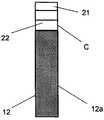
이들 판이, 끝판(11a)의 배면과 제1판(12a)의 전면, 제1판(12a)의 배면과 제2판(13a)의 전면, 제2판(13a)의 배면과 제3판(12b)의 전면, 제3판(12b)의 배면과 제4판(13b)의 전면, 제4판(13b)의 배면과 제5판(12c)의 전면, 및 제5판(12c)의 배면과 끝판(11b)의 전면이 이 순서로 접합함으로써 조립되어 제1의 합류 형성장치(3)가 형성되어 있다. 각각의 판의 접합부분에는 필요에 따라 액체누설을 막는 수단이 설치된다. 도 1에 있어서, Y축방향으로 각 판의 면을 보았을 때 앞측이 전 면, 뒤측이 배면으로 되어 있다. 도 4는 제1판(12a)의 정면도이다. 도 5는 도 4에 있어서의 S1-S1 화살표방향에서 본 단면도이다. 제1판(12a)은 그 최상부에 액체흐름 도입개구(21)를 갖고, 또 개구(21)로부터 확개된 공간으로 이루어지는 액체저장부(22)를 갖는다. 제3판(12b) 및 제5판(12c)은 상술과 같이, 이 형태에 있어서는 제1판(12a)과 같은 구조를 갖는다. 또, 이하에 있어서 제1판(12a), 제3판(12b) 및 제5판(12c)을 액체흐름 도입판(12)이라고 총칭하는 경우가 있다.These plates include the back of the
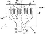
도 6은 제2판(13a)의 정면도이다. 도 7은 도 6에 있어서의 S2-S2 화살표방향에서 본 단면도, 및 도 8은 도 6에 있어서의 S3-S3 화살표방향에서 본 단면도이다. 제2판(13a)의 내측의 상부에 다수의 슬릿격벽(31)이 간격을 두고 설치되어 있다. 인접하는 슬릿격벽(31) 사이에는 제2판(13a)의 전면으로부터 배면으로 관통하는 슬릿(32)이 형성되어 있다. 다수의 슬릿격벽(31)과 다수의 슬릿(32)으로 슬릿부(33)가 형성되어 있다. 이 형태에 있어서는, 다수의 슬릿(32)은 2종류의 슬릿, 즉 슬릿(32a)으로 이루어지는 제1의 슬릿군과 슬릿(32b)으로 이루어지는 제2의 슬릿군으로 이루어진다.6 is a front view of the
제1의 슬릿군을 형성하는 슬릿(32a)의 종단면형상이 도 7에 나타내어진다. 제2의 슬릿군을 형성하는 슬릿(32b)의 종단면형상이 도 8에 나타내어진다. 도 7 및 도 8에 나타내어지는 바와 같이, 슬릿(32a)의 능선(34a)과 각 슬릿(32b)의 능선(34b)은 제2판(13a)의 두께방향(도 7 및 도 8에 있어서의 Y축방향)에 대하여 경사져 있다. 능선(34a)의 경사방향과 능선(34b)의 경사방향은 서로 역방향으로 되어 있다. 제4판(13b)은 상술과 같이, 이 형태에 있어서는 제2판(13a)과 같은 구조를 갖는다. 또, 이하에 있어서 제2판(13a)과 제4판(13b)을 슬릿판(13)이라고 총칭하는 경우가 있다.The longitudinal cross-sectional shape of the
3장의 액체흐름 도입판(12)(제1판(12a), 제3판(12b), 제5판(12c))과 2장의 슬릿판(13)(제2판(13a), 제2판(13b))이 교대로 적층된 상태에 있어서의 도 6의 S2-S2 화살표방향에서 본 방향과 같은 화살표방향에서 본 방향의 단면도가 도 9에 나타내어진다. 같은 적층상태에 있어서의 도 6의 S3-S3 화살표방향에서 본 방향과 같은 화살표방향에서 본 방향의 단면도가 도 10에 나타내어진다.Three liquid flow introduction plates 12 (
도 9 및 도 10에 있어서, 각 액체흐름 도입판(12)에 있어서의 액체저장부(22)의 저면(23)의 액체흐름 도입판(12)의 저변(BL)으로부터의 높이방향의 위치는 능선(34a)의 상단부(41a)와 하단부(42a) 사이에 위치함과 아울러, 능선(34b)의 상단부(41b)와 하단부(42b) 사이에 위치한다.9 and 10, the position in the height direction from the bottom side BL of the liquid
이 배치에 의해, 도 9에 있어서 액체저장부(22)로부터 능선(34a)의 상단부(41a)측을 통과하여 제1의 액체흐름(51a)이 제2판(13a)의 슬릿(32a)으로 유입되지만, 능선(34a)의 하단부(42a)측에서부터는 슬릿(32a)이 봉쇄된 상태로 되어 있으므로 제1의 액체흐름(51a)은 제4판(13b)의 슬릿(32a)으로 유입되지 않는다. 한편, 도 9 및 도 10에 있어서 액체저장부(22)로부터 능선(34a)의 상단부(41a)측을 통과하여 제2의 액체흐름(51b)이 제4판(13b)의 슬릿(32a)으로 유입되지만, 능선(34a)의 하단부(42a)측으로부터는 슬릿(32a)이 봉쇄된 상태로 되어 있으므로 제2의 액체흐름(51b)은 제2판(13a)의 슬릿(32a)으로 유입되지 않는다. 또한, 이 배치에 의해 도 10에 있어서 액체저장부(22)로부터 능선(34b)의 상단부(41b)측을 통과하여 제1의 액체흐름(51a)이 제4판(13b)의 슬릿(32b)으로 유입되지만, 능선(34b)의 하단부(42b)측에서부터는 슬릿(32b)이 봉쇄된 상태로 되어 있으므로 제1의 액체흐름(51a)은 제2판(13a)의 슬릿(32b)으로 유입되지 않는다. 한편, 도 9 및 도 10에 있어서 액체저장부(22)로부터 능선(34b)의 상단부(41b)측을 통과하여 제2의 액체흐름(51b)이 제2판(13a)의 슬릿(32b)으로 유입되지만, 능선(34b)의 하단부(42b)측에서부터는 슬릿(32b)이 봉쇄된 상태로 되어 있으므로 제2의 액체흐름(51b)은 제4판(13b)의 슬릿(32b)으로 유입되지 않는다.By this arrangement, in FIG. 9, the
이렇게 해서, 도 9에 있어서 제3판(12b)의 제1의 액체흐름(51a)이 공급되는 액체저장부(22)로부터 제1의 액체흐름(51a)이 제2판(13a)의 슬릿(32a)으로 유입된다. 또, 제5판(12c)의 제2의 액체흐름(51b)이 공급되는 액체저장부(22)로부터 제2의 액체흐름(51b)이 제4판(13b)의 슬릿(32a)으로 유입된다. 한편, 도 10에 있어서 제3판(12b)의 제1의 액체흐름(51a)이 공급되는 액체저장부(22)로부터 제1의 액체흐름(51a)이 제4판(13b)의 슬릿(32b)으로 유입된다. 또, 제1판(12a)의 제2의 액체흐름(51b)이 공급되는 액체저장부(22)로부터 제2의 액체흐름(51b)이 제2판(13a)의 슬릿(32b)으로 유입된다.In this way, in FIG. 9, the
이 형태에 있어서는, 슬릿판(13)은 슬릿부(33)의 하방에, 제1의 층형상 액체흐름을 형성하는 제1의 합류부(61)를 더 갖는다. 슬릿부(33)의 각 슬릿을 통과함으로써 형성된 층형상의 각 액체흐름(51a, 51b)은 층형상의 형태가 유지된 상태로 제1의 합류부(61)에서 합류한다. 이 합류에 의해 층형상 액체흐름(51)이 형성된다. 층형상 액체흐름(51)은 슬릿판(13)의 저변(BL)에 형성되어 있는 제1의 합류부 출 구(62)로부터 다음에 이어지는 액체유로로 유출된다. 이렇게 해서, 제1의 합류 형성장치(3)에 의해 적어도 2개의 층형상 액체흐름(51)이 형성된다.In this embodiment, the
여기서 끝판(11), 액체도입판(12), 슬릿판(13) 등에 사용되는 재료는 종래의 액체흐름의 합류장치의 부품을 형성하는 재료로서 사용되는 철 등의 금속, 스테인레스강 등의 합금, 또는 열적, 치수정밀도적으로 문제가 없을 경우는 수지 등이다. 특히 강도, 가공 적성, 치수정밀도, 내열성, 내부식성의 점에서 스테인레스강이 바람직하다.The material used for the
층형상 액체흐름(51)을 형성하는 액체흐름(51a)과 액체흐름(51b)의 각각은 액체흐름 공급장치(2)로부터 제1의 합류 형성장치(3)로 공급된다. 도 1에 있어서, 액체흐름 공급장치(2)는 액체흐름 도입판(12)에 있어서의 액체흐름 도입개구(21)에 결합된 액체흐름 공급포트(72a, 71, 및 72b)를 갖는다. 액체흐름 공급포트(71)는 제1의 액체흐름(L1(51a))을 공급하는 제1의 액체흐름 공급관(73)에 결합되어 있다. 액체흐름 공급포트(72a, 72b)는 제2의 액체흐름(L2(51b))을 공급하는 제2의 액체흐름 공급관(74)에 결합되어 있다. 제1의 액체흐름 공급관(73)은 제1의 액체흐름 공급원(도시생략)에 결합되고, 제2의 액체흐름 공급관(74)은 제2의 액체흐름 공급원(도시생략)에 결합되어 있다.Each of the
액체흐름 공급장치(2)로부터 제1의 합류 형성장치(3)에 각각 공급된 제1의 액체흐름(L1(51a))과 제2의 액체흐름(L2(51b))은, 상술한 바와 같이 제2판(13a)의 제1의 합류부 출구(62)로부터 액체흐름(51a)과 액체흐름(51b)이 교대로 층형상으로 위치하는 제1의 층형상 액체흐름(81)으로 되어 유출되고, 또 제4판(13b)의 제1의 합류부 출구(62)로부터 액체흐름(51a)과 액체흐름(51b)이 교대로 층형상으로 위치하는 제2의 층형상 액체흐름(82)으로 되어 유출된다. 이 상태가 도 11에 나타내어진다. 또, 이 형태에 있어서는 제1의 층형상 액체흐름(81)과 제2의 층형상 액체흐름(82)은 같은 층형상구조를 갖고 있다.As described above, the first
도 11은 제2의 합류 형성장치(4)의 정면 개략모식도이다. 도 11에 있어서, 제2의 합류 형성장치(4)는 제1의 층형상 액체흐름(81)이 그 층형상이 유지된 상태에서 흐르는 유로(81a 및 81b), 제2의 층형상 액체흐름(82)이 그 층형상이 유지된 상태에서 흐르는 유로(82a 및 82b), 및 유로(81a, 81b)를 흘러 온 제1의 층형상 액체흐름(81)과 유로(2a, 82b)를 흘러 온 제2의 층형상 액체흐름(82)이 합류하여, 합성 층형상 액체흐름(83)이 형성되는 제2의 합류부(84)로 이루어진다.11 is a schematic front view of the second
도 12는 도 11에 있어서의 액체흐름의 유동방향에서의 4개소의 유로횡단면의 개략을 순차 배열한 도면이다. 도 12(a)는 도 11에 있어서의 S4-S4 화살표방향에서 본 단면도, 도 12(b)는 도 11에 있어서의 S5-S5 화살표방향에서 본 단면도, 도 12(c)는 도 11에 있어서의 S6-S6 화살표방향에서 본 단면도, 및 도 12(d)는 도 11에 있어서의 S7-S7 화살표방향에서 본 단면도이다.FIG. 12 is a diagram in which the outlines of four flow path transverse cross sections in the flow direction of the liquid flow in FIG. 11 are arranged in sequence. FIG. Fig. 12 (a) is a sectional view seen from the arrow S4-S4 in Fig. 11, Fig. 12 (b) is a sectional view seen from the arrow S5-S5 in Fig. 11, and Fig. 12 (c) is shown in Fig. 11 Is a sectional view seen from the arrow direction S6-S6, and FIG. 12 (d) is a sectional view seen from the arrow direction S7-S7 in FIG.
도 12(a)에는, 유로(81a)의 입구부에 있어서의 제1의 층형상 액체흐름(81)과 유로(82a)의 입구부에 있어서의 제2의 층형상 액체흐름(82)의 위치관계가 나타내어져 있다. 도 12(b)에는, 도 12(a)에 있어서 Y축방향(도 11의 지면에 수직인 방향)으로 배열되어 있었던 유로(81a)와 유로(82a)가, X축방향(도 11의 지면에 있어서의 좌우방향)으로 그들의 배열상태가 바뀐 상태에 있어서의 제1의 층형상 액체흐 름(81)과 제2의 층형상 액체흐름(82)의 위치관계가 나타내어져 있다. 도 12(c)에는, 제2의 합류부(84)의 입구부에 있어서의 제1의 층형상 액체흐름(81)과 제2의 층형상 액체흐름(82)의 위치관계가 나타내어져 있다. 도 12(d)에는, 제2의 합류부(84)의 출구부에 있어서 제1의 층형상 액체흐름(81)과 제2의 층형상 액체흐름(82)이 합류되어 합성 층형상 액체흐름(83)이 형성된 상태가 나타내어져 있다.12 (a), the position of the first
이 형태에 있어서, 슬릿부(33)를 갖는 제2판(13a)과 제4판(13b)이, 본 발명에서 말하는 각 액체흐름의 각각이 통과하는 다수의 슬릿이 형성된 요소A에 해당되고, 요소A는 각각 독립적으로 2개 존재한다. 제1의 합류부(61)를 갖는 제2판(13a)과 제4판(13b)이, 본 발명에서 말하는 제1의 층형상 액체흐름을 형성하는 제1의 합류부가 형성된 요소B에 해당되고, 각각 독립적으로 2개 존재한다. 액체저장부(22)를 갖는 액체흐름 도입판(12)이, 본 발명에서 말하는 각 요소A에 각 액체흐름을 공급하는 액체저장부가 형성된 요소C에 해당된다. 또, 제1의 층형상 액체흐름(81)과 제2의 층형상 액체흐름(82)을 합류시켜 합성 층형상 액체흐름(83)을 형성하는 제2의 합류 형성장치(4)가, 본 발명에서 말하는 각 요소B에서 형성된 각 제1의 층형상 액체흐름이 소정의 순서로 층형상으로 합류하여 제2의 층형상 액체흐름을 형성하는 제2의 합류부가 형성된 요소D에 해당된다.In this aspect, the
본 발명의 액체흐름의 합류장치를 이용하여 층수가 700이상인 다층 필름을 제조할 경우, 제1의 합류 형성장치(3)에 있어서 다수의 요소A와 그것에 대응하는 수의 요소B가 형성된다.When a multilayer film having a layer number of 700 or more is manufactured by using the confluence device of the liquid flow of the present invention, a large number of elements A and a corresponding number of elements B are formed in the first
도 13에, 별도의 형태의 제1의 합류 형성장치(3a)에 있어서의 요소A, 요소B 및 요소C를 형성하는 각 판을 도 3의 경우와 마찬가지로 순차 전개한 상태가 나타내어진다. 이 형태에 있어서의 제1의 합류 형성장치(3a)는 끝판(11a), 제1판(12a), 제2판(13a), 제3판(12b), 제4판(13b), 제5판(12c), 제6판(13c), 제7판(12d), 제8판(13d), 제9판(12e), 및 끝판(11b)으로 이루어진다. 제2판(13a), 제4판(13b), 제6판(13c), 및 제8판(13d)에는 각각 요소A와 요소B가 형성되어 있다. 즉, 제1의 합류 형성장치(3a)에 있어서는, 요소A는 각각 독립적으로 4개 존재하고, 요소B는 각각 독립적으로 4개 존재한다. 또, 제1판(12a), 제3판(12b), 제5판(12c), 제7판(12d), 및 제9판(12e)에는 각각 요소C가 형성되어 있다. 이들 판의 조립은 도 3의 형태의 경우와 마찬가지로 행해진다.In FIG. 13, the state which developed each board | substrate which forms the element A, the element B, and the element C in the 1st
도 13에 나타내어진 제1의 합류 형성장치(3a)를 사용한 경우의 층형상 액체흐름이 형성되는 상태가, 도 11 및 도 12의 경우와 마찬가지로 도 14 및 도 15에 나타내어진다. 제1의 합류 형성장치(3a)에서 제1의 층형상 액체흐름(91), 제2의 층형상 액체흐름(92), 제3의 층형상 액체흐름(93), 및 제4의 층형상 액체흐름(94)이 형성된다. 형성된 각각의 층형상 액체흐름은 유로(91a 및 91b), 유로(92a 및 92b), 유로(93a 및 93b), 및 유로(94a 및 94b)를 각각 흘러 제2의 합류부(96)에 이른다. 제2의 합류부(96)에 있어서, 각 층형상 액체흐름은 합류하여 합성 층형상 액체흐름(95)을 형성한다.The state in which the layered liquid flow is formed when the first
이러한 다수개의 요소A와 요소B가 구비된 제1의 합류 형성장치를 사용함으로써, 높은 정밀도를 유지하면서 700이상의 층으로 이루어지는 여러 가지의 다층 필름의 제조가 가능해진다.By using such a first confluence forming apparatus provided with a plurality of elements A and B, it is possible to manufacture various multilayer films consisting of 700 or more layers while maintaining high precision.
구체적으로는, 액체흐름(L1)에 의해 형성되는 층과 액체흐름(L2)에 의해 형성되는 층이 L1(1)/L2(1)/L1(2)/L2(2)L1(3)/L2(3)/····/L1(n-1)/L2(n-1)/L1(n)의 순서로 적층될 경우, 액체흐름(L1)에 의해 형성되는 층에 대해서는 L1(1)로부터 L1(n)에 이를수록 층의 두께가 서서히 얇아지고, 액체흐름(L2)에 의해 형성되는 층에 대해서는 L2(1)로부터 L2(n-1)에 이를수록 층의 두께가 서서히 두꺼워지는 다층 필름의 제조도 가능하다. 여기서 n은 어느 한쪽의 표면으로부터 세었을 경우의 액체흐름(L1) 또는 액체흐름(L2)에 의해 형성되는 층의 층번호이다.Specifically, the layer formed by the liquid flow L1 and the layer formed by the liquid flow L2 are L1 (1) / L2 (1) / L1 (2) / L2 (2) L1 (3) / When stacked in the order of L2 (3) / ... L1 (n-1) / L2 (n-1) / L1 (n), L1 (1) for the layer formed by the liquid flow L1; The thickness of the layer gradually decreases from L2 (n) to L1 (n), and the thickness of the layer gradually increases from L2 (1) to L2 (n-1) for the layer formed by the liquid flow (L2). Production of multilayer films is also possible. N is the layer number of the layer formed by the liquid flow L1 or the liquid flow L2 when it counts from either surface.
또한, 액체흐름(L1)에 의해 형성되는 층에 대해서는, L1(1)에서 L1(n/2)에 이르는 부분에서는 층의 두께가 서서히 두꺼워지고, L1((n+1)/2)에서 L1(n)에 이르는 부분에서는 층의 두께가 서서히 얇아지는 한편, 액체흐름(L2)에 의해 형성되는 층에 대해서는, L2(1)에서 L2((n-1)/2)에 이르는 부분에서는 층의 두께가 서서히 얇아지고, L2((n)/2)에서 L2(n-1)에 이르는 부분에서는 층의 두께가 서서히 두꺼워지는 다층 필름의 제조도 가능하다. 여기서 n은, 어느 한쪽의 표면으로서부터 세었을 경우의 액체흐름(L1) 또는 액체흐름(L2)에 의해 형성되는 층의 층번호이다.In addition, with respect to the layer formed by the liquid flow L1, the thickness of the layer is gradually thickened at a portion from L1 (1) to L1 (n / 2), and L1 ((n + 1) / 2) to L1. In the part reaching (n), the thickness of the layer gradually decreased, while for the layer formed by the liquid flow L2, in the part ranging from L2 (1) to L2 ((n-1) / 2), It is also possible to manufacture a multilayer film in which the thickness is gradually thinned and the thickness of the layer is gradually thickened at a portion from L2 ((n) / 2) to L2 (n-1). N is the layer number of the layer formed by the liquid flow L1 or the liquid flow L2 when it counts from either surface.
종래의 기술에서는, 적층수를 매우 많게 하고자 하면 스태틱 믹서를 사용하지 않을 수 없었으므로, 같은 층두께에서의 적층체나, 각 층의 두께가 순차 두꺼워지거나 혹은 각 층의 두께가 순차 얇아지는 형태의 각 층의 두께가 단순히 일방향으로 증가 혹은 감소하는 적층체나, 제어할 수 없는 액체흐름의 흐름의 편차에 의해 생기는 랜덤한 층두께를 갖는 적층체밖에 얻어지지 않았다.In the prior art, if the number of stacks is to be very large, a static mixer has to be used, so that the stacks at the same layer thickness or the thickness of each layer are sequentially thickened or the thickness of each layer is gradually thinned. Only laminates in which the thickness of the layer simply increases or decreases in one direction, or laminates having random layer thicknesses caused by uncontrollable flow of liquid flow are obtained.
본 발명에 의하면, 층두께가 각 슬릿의 형상, 특히 슬릿간극 및/또는 슬릿길 이의 조정에 의해 제어 가능하고, 또 요소A를 2개이상 독립적으로 갖고 있으므로 종래는 불가능했던 매우 많은 층수에 있어서도 임의의 층구성의 설계가 가능하다.According to the present invention, the layer thickness can be controlled by adjusting the shape of each slit, in particular, the slit gap and / or the slit length, and has two or more elements A independently. It is possible to design the layer structure.
요소A가 갖는 슬릿의 수는 10개이상 400개이하인 것이 바람직하다. 보다 바람직하게는 100개이상 350개이하이다. 슬릿의 수가 10개보다 적으면, 매우 많은 요소A가 필요하게 되므로 각 요소의 위치맞춤을 하는 것이 어려워진다. 이러한 장치를 사용하면 적층체의 제조비용의 점에서 불리하다. 또, 장치가 Y축방향(도 1 참조)으로 대형화되므로 바람직하지 않다. 한편, 슬릿수가 400개보다 많을 경우에는 장치가 X축방향(도 2 참조)으로 지나치게 대형화되므로, 장치 내에 유동하는 액체흐름의 체류부가 생기거나 X축방향의 단부측에 위치하는 슬릿에서의 액체흐름의 유속이 불균일해지거나 한다. 따라서, 슬릿수가 400개보다 많은 장치는 바람직하지 않다. 슬릿의 수가 100개이상 350개이하이면, 장치는 X축방향·Y축방향으로 균형이 잡힌 크기로 되어 사용하기 쉬운 장치로 된다. 이러한 장치에 있어서는, 장치 내에 있어서의 액체흐름의 체류부가 생기기 어려워지는 것 외에, 액체흐름의 불균일한 유속이 발생하지 않는다. 이러한 장치를 사용함으로써, 효율적으로 매우 많은 층수를 갖는 적층체를 제조할 수 있게 된다.It is preferable that the number of slits which element A has is 10 or more and 400 or less. More preferably, it is 100 or more and 350 or less. If the number of slits is less than ten, very many elements A are required, and it becomes difficult to align each element. Use of such a device is disadvantageous in terms of the manufacturing cost of the laminate. Moreover, since the apparatus is enlarged in the Y-axis direction (see Fig. 1), it is not preferable. On the other hand, if the number of slits is more than 400, the device is excessively large in the X-axis direction (see FIG. 2), so that a liquid flow portion in the device flows in the slit located at the end side in the X-axis direction. The flow rate of the oil becomes uneven. Thus, devices with more than 400 slits are undesirable. If the number of slits is 100 or more and 350 or less, the device becomes a size well balanced in the X-axis direction and the Y-axis direction, thereby making the device easy to use. In such an apparatus, a retention portion of the liquid flow in the apparatus becomes less likely to occur, and a nonuniform flow rate of the liquid flow does not occur. By using such an apparatus, it is possible to efficiently produce a laminate having a very large number of layers.
슬릿의 간극은 10㎛이상 30,000㎛이하인 것이 바람직하다. 슬릿의 간극이란, 도 6의 슬릿(32a) 및 슬릿(32b)에 있어서 슬릿의 X축방향의 폭을 말한다. 슬릿의 간극은 보다 바람직하게는 100㎛이상 10,000㎛이하이다. 슬릿의 간극이 10㎛보다 작을 경우에는 가공정밀도 한계 때문에 슬릿에 있어서의 균일한 유량제어를 행하는 것이 어렵게 된다. 슬릿의 간극이 30,000㎛보다 클 경우에는 장치가 X축방향으로 지나치게 대형화된다. 또, 액체흐름의 유량에 따라서는 각 슬릿에서의 압력손실이 지나치게 작아지므로 각 슬릿을 흐르는 액체흐름의 유량을 균일하게 할 수 없게 되는 경우가 있다. 슬릿의 간극이 100㎛이상 10,000㎛이하이면, 장치가 대형화되는 일 없이 각 층을 형성하는 액체흐름의 폭방향(Y축방향)의 분포나 각 층 사이의 두께분포 등의 균일성이 유지되고, 그 결과 매우 적층정밀도가 높은 적층체가 얻어진다.It is preferable that the clearance gap of a slit is 10 micrometers or more and 30,000 micrometers or less. The gap between the slits means the width of the slits in the
슬릿의 길이는 20㎜이상 200㎜이하인 것이 바람직하다. 슬릿의 길이란, 도 6의 슬릿(32a) 및 슬릿(32b)에 있어서 슬릿의 Z축방향의 길이를 말한다. 슬릿의 길이는 보다 바람직하게는 30㎜이상 100㎜이하이다. 슬릿의 길이가 20㎜보다 짧으면, 슬릿에서의 액체흐름의 압력손실이 지나치게 작아지므로 각 슬릿을 흐르는 액체흐름의 유량을 균일하게 제어할 수 없게 되는 경우가 있다. 또, 슬릿 내부에서 Y축방향으로 액체흐름의 유속분포가 생기므로, 폭방향(Y축방향)에 있어서 액체흐름의 적층편차가 발생한다. 한편, 슬릿의 길이가 200㎜보다 길면, 액체흐름의 압력손실이 지나치게 커지므로 액체흐름의 장치로부터의 누설이 발생하기 쉬워진다. 또한, 장치를 반복해서 사용하고 있으면, 슬릿이 변형되거나 하는 일이 있다.It is preferable that the length of a slit is 20 mm or more and 200 mm or less. The length of a slit means the length of the slit in the Z-axis direction in the
슬릿의 폭은 10㎜이상 200㎜이하인 것이 바람직하다. 슬릿의 폭이란, 도 6의 슬릿(32a) 및 슬릿(32b)에 있어서 Y축방향(도 7 및 도 8 참조)의 길이를 말한다. 슬릿의 폭은 보다 바람직하게는 20㎜이상 100㎜이하이다. 슬릿의 폭이 10㎜보다 작을 경우에는 슬릿의 강도가 부족하여 슬릿이 변형되기 쉬워진다. 슬릿의 폭이 200㎜보다 클 경우에는 슬릿간극을 정밀도 좋게 가공할 수 없게 된다. 또, Y축방향에 서의 액체흐름의 유속분포가 커진다.It is preferable that the width of a slit is 10 mm or more and 200 mm or less. The width of the slit refers to the length of the
슬릿은 슬릿의 입구부와 출구부에서의 압력손실차가 0.5㎫이상 10㎫이하로 되도록 상기의 슬릿간극, 길이, 혹 폭을 조정함으로써 설계되어 있는 것이 바람직하다. 압력손실차는 보다 바람직하게는 1㎫이상 8㎫이하이다. 압력손실차가 0.5㎫보다 작을 경우, 각 슬릿 내의 액체흐름이 설계된 대로의 유량으로 균일하게 흐르지 않기 때문에 액체흐름의 적층정밀도가 나빠진다. 압력손실차가 8㎫보다 클 경우, 합류장치 내의 전체의 압력손실차가 지나치게 커지므로 액체흐름 공급장치에 큰 부하가 걸린다. 또, 반복사용에 의해 슬릿형상이 변형되므로 액체흐름의 적층정밀도가 나빠지기 쉽다.The slit is preferably designed by adjusting the slit gap, length, or width so that the pressure loss difference between the inlet and the outlet of the slit is 0.5 MPa or more and 10 MPa or less. The pressure loss difference is more preferably 1 MPa or more and 8 MPa or less. When the pressure loss difference is smaller than 0.5 MPa, the stacking accuracy of the liquid flow becomes poor because the liquid flow in each slit does not flow uniformly at the designed flow rate. If the pressure loss difference is larger than 8 MPa, the total pressure loss difference in the confluence device becomes too large, and a large load is applied to the liquid flow supply device. In addition, since the slit shape is deformed by repeated use, the lamination accuracy of the liquid flow tends to be poor.
요소A의 슬릿부(33)(도 6 참조)가, 슬릿형상이 X축방향으로 단계적으로 변화되고 있는 부위(슬릿군)를 포함하고 있는 것이 바람직하다. 이렇게 함으로써 적층체 중에 층두께가 서서히 변화되는 부위를 용이하게 형성할 수 있다. 이 형태는, 예를 들면 간섭반사 필름의 제조에 바람직하게 사용된다. 이것에 의해 간섭반사 필름의 반사대역의 광대역화가 용이해진다. 또, 굴절율제어 필름의 제조에 바람직하게 사용된다. 이것에 의해 필름 내부의 굴절율이 서서히 변화되는 필름의 제조가 가능해진다.It is preferable that the slit part 33 (refer FIG. 6) of the element A contains the site | part (slit group) in which the slit shape is changing stepwise in the X-axis direction. By doing in this way, the site | part which a layer thickness changes gradually in a laminated body can be formed easily. This form is used suitably for manufacture of an interference reflection film, for example. This makes it easy to widen the reflection band of the interference reflection film. Moreover, it is used preferably for manufacture of a refractive index control film. Thereby, manufacture of the film by which the refractive index inside a film changes gradually is attained.
본 발명에 있어서의 요소C에 있어서의 액체저장부(22)(도 4 참조)는 요소A의 슬릿에 액체흐름을 분배하는 기능을 갖는다. 액체저장부(22)가 있음으로써 효율적으로 슬릿으로 액체흐름을 공급할 수 있다. 또, 슬릿 내를 흐르는 액체흐름의 유량이 기본적으로는 슬릿에 있어서의 액체흐름의 압력손실로 결정되게 되므로, 요소A 내의 각 슬릿내를 흐르는 액체흐름의 각 유량을 슬릿간극이나 슬릿길이만으로 제어할 수 있게 된다. 이것에 의해 요소A의 설계가 용이해지는 것은 물론, 합류장치 전체의 설계도 용이해진다.The liquid reservoir 22 (see Fig. 4) in the element C in the present invention has a function of distributing the liquid flow to the slit of the element A. The presence of the
요소A의 액체흐름의 공급면측과 액체흐름의 비공급면측의 슬릿의 종단면적이 다른 것이 보다 바람직하다. 이 형태의 예가 도 7에 나타내어진다. 도 7에 있어서의 슬릿(32a)과 같이, 슬릿의 간극(도 6 참조)은 일정하면서 액체흐름의 공급면측의 슬릿길이(LS2)와 액체흐름의 비공급면측의 슬릿길이(LS1)가 다르면 좋다. 액체흐름의 공급면측의 슬릿길이(LS2)가 액체흐름의 비공급면측의 슬릿길이(LS1)보다 긴 것이 보다 바람직하다. 이렇게 함으로써 요소C와 요소A를 직접 연결하고, 제1의 액체흐름(51a)과 제2의 액체흐름(51b)이 교대로 적층된 다층구조를 갖는 층형상 액체흐름(51)을 형성하는 것이 용이해진다. 이러한 단면적이 다른 구조로 하기 위해서는 도 7 및 도 8에 나타내는 바와 같이, 슬릿(32a, 32b)의 Y-Z축면이 사다리꼴 형상으로 되어 있는 것이 바람직하다.More preferably, the longitudinal area of the slit on the supply surface side of the liquid flow of the element A and the non-feed surface side of the liquid flow is different. An example of this form is shown in FIG. 7. Similar to the
요소C와 요소A가 직접 연결되어 있으면, 제1의 합류 형성장치(3)의 부품수가 적어져 장치의 소형화가 가능해진다. 또, 구성요소C와 구성요소A의 위치맞춤 정밀도가 높지 않아도 좋고, 또한 압력손실의 조정을 슬릿의 간극만으로 제어할 수 있으므로 보다 높은 적층정밀도를 갖는 적층체를 얻는 것이 가능해진다. 또, Y축방향에 있어서의 액체흐름의 유량분포의 차가 작아지므로 Y축방향의 다른 위치에 있어서의 액체흐름의 적층정밀도도 높은 것으로 된다.When the element C and the element A are directly connected, the number of parts of the first
도 3 혹은 도 13에 나타낸 형태는, 도 7 및 도 8에 나타내는 바와 같이 능 선(34a) 혹은 능선(34b)으로 나타내는 슬릿의 저면을 경사시키고, 또 능선(34a)의 하단부(42a) 혹은 능선(34b)의 하단부(42b)와 액체저장부(22)의 저면(23)의 위치관계를 도 9 및 도 10에 나타내는 바와 같이 선정함으로써, 요소C의 액체저장부(22)에서 슬릿부(33)에 이르는 액체흐름을 슬릿(32a)에는 유입시키고, 슬릿(32a)의 옆의 슬릿(32b)에는 유입시키지 않도록 한 구조를 갖는다. 이 형태에 있어서는, 요소A의 각 슬릿의 액체흐름의 입구는 도 9에 있어서의 능선(34a)의 상단부(41a)와 액체저장부(22)의 저면(23) 사이의 높이와 슬릿(32a)의 슬릿간극으로 형성되는 면, 혹은 도 10에 있어서의 능선(34b)의 상단부(41b)와 액체저장부(22)의 저면(23) 사이의 높이와 슬릿(32b)의 슬릿간극으로 형성되는 면에 의해 형성된다. 그러나 요소A의 각 슬릿의 액체흐름의 입구의 형성방법은 이 형태에 한정되는 것은 아니다. 도 16에 다른 형태가 나타내어진다.3 and 13, the bottom surface of the slit represented by the
도 16에, 도 3 혹은 도 13에 나타내는 판의 배열과는 다른 형태의 판의 배열이 나타내어진다. 단, 도 16에 있어서는 판의 배열의 양단에 있는 끝판은 생략되어 있다. 이들 끝판으로서는 도 3 혹은 도 13에 나타내는 끝판(11a) 및 끝판(11b)과 같은 것이 사용된다.In FIG. 16, the arrangement | positioning of the board of a form different from the arrangement of the board | plate shown in FIG. 3 or FIG. 13 is shown. 16, the end plates at both ends of the arrangement of the plates are omitted. As these end plates, the same thing as the
도 16에 나타내는 판의 배열은 제1판(112a), 제2판(113a), 제3판(114a), 제4판(113b), 및 제5판(112b)으로 이루어진다. 도 16에 있어서의 제1판(112a) 및 제5판(112b)은 도 3에 있어서의 제1판(12a) 및 제3판(12b)과 같고, 액체저장부를 갖는 요소C를 형성한다. 도 16에 있어서, 제3판(114a)은 도 3에 있어서의 제2판(13a)의 슬릿판에 대응하는 슬릿판이지만, 도 3에 있어서의 슬릿판과 다른 점은, 도 16의 슬릿판에서는 각 슬릿의 길이(Z축방향의 슬릿벽의 길이)가 모두 같은 점이다.The arrangement of the plate shown in FIG. 16 includes a
도 16의 형태에서는, 슬릿판의 각 슬릿의 길이가 모두 같기 때문에, 소정 슬릿과 그 옆의 슬릿으로의 요소C의 액체저장부로부터의 액체흐름의 유입을 선택적으로 행하게 하기 위해 제2판(113a)및 제4판(113b)이, 요소C를 형성하는 제1판(112a)과 요소A를 형성하는 제3판(114a) 사이에 설치되어 있다. 제2판(113a)에는 간격을 두고 구멍(121a)이 형성되어 있다. 각 구멍(121a)은 제3판(114a)의 전체 슬릿에 대하여 1개 걸러의 슬릿에 대응하는 위치관계를 가지고 제2판(113a)에 형성되어 있다. 제4판(113b)에는 제2판(113a)과 마찬가지로, 간격을 두고 구멍(121b)이 형성되어 있다. 각 구멍(121b)은 제3판(114a)의 전체 슬릿에 대하여 1개 걸러의 슬릿에 대응하는 위치관계를 가지고 제4판(113b)에 형성되어 있다. 단, 제2판(113a)의 구멍(121a)과 제4판(113b)의 구멍(121b)의 위치는 제3판의 슬릿위치에 대하여 1개의 슬릿위치만큼 어긋난 관계에 있다. 이 구성으로부터, 제1판(112a)으로부터 공급되는 액체흐름(제1의 액체흐름)과 제5판(112b)으로부터 공급되는 액체흐름(제2의 액체흐름)은 인접하는 슬릿에 각각 따로따로 공급된다. 또, 이하에 있어서 구멍(121a)을 갖는 제2판(113a)과 구멍(121b)을 갖는 제4판(113b)을 액체흐름 도입구멍판(113)이라고 총칭하는 경우가 있다.In the form of FIG. 16, since the lengths of each slit of the slit plate are all the same, the
도 16에 있어서는 적어도 1세트 더 필요한 제2판(113a), 제3판(114a), 제4판(113b), 및 제5판(112b)의 세트에 상당하는 세트의 도시가 생략되어 있다. 또, 이 형태에 있어서는 슬릿을 통과하여 형성된 층형상의 제1의 액체흐름과 층형상의 제2의 액체흐름이 합류하여, 제1의 층형상 액체흐름을 형성하는 제1의 합류부가 형 성된 요소B는 도 3의 제2판(13a)의 경우와 마찬가지로 제3판(114a)에 있어서 그 슬릿부의 하방에 형성되어 있다. 액체흐름 도입구멍판(113)의 구멍(121a, 121b)의 형상은 원형, 사각형 및 사다리꼴 등 어떤 형상이어도 된다.In FIG. 16, illustration of the set corresponding to the set of the
액체흐름이 선택적으로 통과하는 구멍(121a)의 군과 구멍(121b)의 군을 사용하는 도 16에 나타내는 형태에 의하면, 요소A의 액체흐름 공급면측과 액체흐름 비공급면측의 슬릿의 단면적을 다르게 할 필요가 있는 도 3에 나타내는 형태에 비해 요소A의 형상이 단순해진다. 단, 도 16에 나타내는 형태에서는 액체흐름 도입구멍판(113)이 필요하므로, 장치를 구성하는 부품점수가 많아지는 것이나, 보다 높은 위치맞춤 정밀도가 요구되게 된다. 또, Y축방향에 있어서의 액체흐름의 유량분포의 차가 커지기 쉽다.According to the form shown in FIG. 16 using the group of the
본 발명에 있어서의 요소A와 요소B는 도 3의 제2판(13a) 혹은 도 16의 제3판(114a)과 마찬가지로 동일한 부품으로 형성되어 있는 것이 바람직하다. 요소A와 요소B가 동일한 부품으로 형성되어 있을 경우, 이들 요소를 제1의 합류 형성장치에 구비할 때 요소A와 요소B 사이의 위치맞춤의 필요가 없어져, 보다 높은 적층정밀도를 갖는 적층체의 제조가 가능해진다.It is preferable that the element A and the element B in this invention are formed from the same component similarly to the
본 발명은 적어도 2개의 각각 독립적으로 형성된 요소A와 그들에 대응하는 요소B에 의해 형성되는 적어도 2개의 제1의 층형상 액체흐름을 합류시켜 제2의 층형상 액체흐름을 형성하기 위한 제2의 합류부가 형성된 요소D를 갖는다.The present invention relates to a method for forming a second layered liquid flow by combining at least two independently formed element A and at least two first layered liquid flows formed by elements B corresponding thereto. The confluence has element D formed.
제2의 합류부가 형성된 요소D의 예는, 이미 도 11에 있어서 제2의 합류 형성장치(4)로서, 혹은 도 14에 있어서 제2의 합류 형성장치(4a)로서 나타내어져 있다. 도 11및 도 12에 나타내는 바와 같이, 제1의 층형상 액체흐름(81)은 유로(81a, 81b)를 통과하여 제2의 합류부(84)로 흐르고, 제2의 층형상 액체흐름(82)은 유로(82a, 82b)를 통과하여 제2의 합류부(84)로 흐른다. 도 14 및 도 15에 있어서도 같은 것이 나타내어져 있다. 층형상 액체흐름(81 및 82)이 제2의 합류부(84)로 흐르는 동안에, 유로(81a)와 유로(82a)의 Y축방향 혹은 X축방향의 위치관계는 유로(81b)와 유로(82b)의 X축방향 혹은 Y축방향의 위치관계로 변경된다. 또, 유로(81b)와 유로(82b)의 횡단면형상은 제2의 합류부(84)에 이르는 동안에 제2의 합류부(84)와 결합시키기 위해 변화되어 있다. 유로의 위치의 변경, 혹은 유로의 횡단면형상의 변화는 서서히 연속적으로 이루어지거나 또는 단계적으로 이루어져도 된다. 보다 바람직하게는, 유로의 횡단면형상의 변화는 횡단면적이 일정하게 유지되는 상태에서 행해지는 것이 바람직하다. 유로의 횡단면적이 일정하면, 유로 내의 액체흐름의 유속분포의 변화가 적고, 합성 층형상 액체흐름(83)에 있어서 각 액체흐름의 높은 적층정밀도를 얻는 것이 용이해진다.The example of the element D in which the 2nd confluence part was formed is already shown as the 2nd
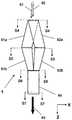
도 17 및 도 18에, 제1의 층형상 액체흐름(81)이 유로(81a)의 입구에서 출구로 흐르는 동안에, 또한 제2의 층형상 액체흐름(82)이 유로(82a)의 입구에서 출구로 흐르는 동안에 유로(81a)와 유로(82a)의 배열방향이 Y축방향으로부터 X축방향으로 변경되는 상태가 나타내어진다. 이 형태에 있어서는, 유로(81a)의 출구를 통과한 제1의 층형상 액체흐름(81)과 유로(82a)의 출구를 통과한 제2의 층형상 액체흐름(82)이 즉시 합류되고, 그 후 유로(82)를 따라 흘러 제2의 합류부(84)에 이른다. 이 유로(82)의 횡단면형상은 제2의 합류부(84)를 향함에 따라 그 X축방향의 변의 길이가 서서히 짧아지고, 그 Y축방향의 변의 길이가 서서히 길어지도록 횡단면적이 일정한 상태를 유지하면서 변화되어 있다. 이 형태와 같이, 제1의 층형상 액체흐름(81)과 제2의 층형상 액체흐름(82)을 합류시킨 후에 그 합류된 액체흐름을 횡단면형상이 변화되는 유로를 따라 흐르게 하여 제2의 합류부(84)에 이르게 해서 이루어지는 합류방법의 쪽이, 도 11에 나타내는 합류방법보다 더 바람직하다.17 and 18, while the first
요소D의 액체흐름의 유동방향의 길이(L)가 하기 식(1)을 충족시키고 있는 것이 바람직하다. 길이(L)가 하기 식의 하한미만이면, 유로의 변형이 지나치게 급격하므로 액체흐름의 유속분포에 편차가 발생하여 적층정밀도의 저하가 생긴다. 또, 길이(L)가 하기 식의 상한보다 클 경우에는 장치가 지나치게 대형화되거나 하므로 장치의 제작, 조립이 곤란해진다.It is preferable that length L of the flow direction of the liquid flow of element D satisfy | fills following formula (1). If the length L is less than the lower limit of the following formula, since the deformation of the flow path is too rapid, deviation occurs in the flow velocity distribution of the liquid flow, resulting in a decrease in lamination accuracy. Moreover, when length L is larger than the upper limit of the following formula, since an apparatus becomes large too much, manufacture and assembly of an apparatus become difficult.

여기서, L은 요소D의 유로길이[m], Q는 액체흐름의 유량[t/h], S는 요소D의 입구부의 총유로단면적(도 12(a), 도 15(a), 혹은 도 18(a)에 있어서의 각 유로의 횡단면적의 합계)[m2]이다.Where L is the flow path length [m] of the element D, Q is the flow rate of the liquid flow [t / h], and S is the total flow path cross-sectional area of the inlet of the element D (FIG. 12 (a), FIG. 15 (a), or FIG. Sum of the cross-sectional area of each flow path in 18 (a)) [m2 ].
요소D의 유로의 횡단면형상은 사각형인 것이 바람직하다. 유로의 횡단면형상이 사각형이 아닐 경우, 횡단면에 있어서의 주변부의 각 액체흐름의 적층상태가 대폭 흐트러지기 때문이다. 사각형의 모서리의 반경(R)이 10㎛이상 1㎜이하인 사각형인 것이 보다 바람직하다. 모서리의 반경(R)이 10㎛미만일 경우에는, 액체흐름의 유로 내에서의 체류의 원인이 되어 액체흐름의 열열화 등이 생기는 경우가 있다. 또, 모서리의 반경(R)이 1㎜를 넘으면, 횡단면에 있어서의 주변부의 각 액체흐름의 적층상태가 악화되는 경우가 있다.It is preferable that the cross-sectional shape of the flow path of the element D is rectangular. This is because when the cross sectional shape of the flow path is not rectangular, the lamination state of each liquid flow in the periphery in the cross section is greatly disturbed. It is more preferable that the radius R of the corner of a rectangle is a rectangle with 10 micrometers or more and 1 mm or less. When the radius R of the edge is less than 10 µm, the liquid flow may be deteriorated in the flow path and thermal degradation of the liquid flow may occur. Moreover, when the radius R of a corner exceeds 1 mm, the lamination | stacking state of each liquid flow in the peripheral part in a cross section may deteriorate.
본 발명의 액체흐름의 합류장치에 있어서, 요소C가 적어도 3개이상 존재하고, 같은 종류의 액체흐름을 2개이상의 요소C에 공급하는데 있어서, 상기 액체흐름의 1개의 공급원에 접속된 액체흐름의 유로(액체흐름의 공급관)를, 상기 2개이상의 요소C에 상기 액체흐름을 동시에 공급할 수 있도록, 도중에 분기시킨 유로(관로)구성으로 하는 것이 바람직하다. 이 예는, 도 1의 제2의 액체흐름 공급관(74)에서 볼 수 있다. 이렇게 함으로써, 필요하게 되는 압출기나 펌프 등의 액체공급장치의 수를 감소시킬 수 있다.In the confluence apparatus of the liquid flow of the present invention, at least three elements C are present, and in supplying two or more elements C of the same kind of liquid flow, the liquid flow connected to one source of the liquid flows It is preferable that the flow path (liquid flow supply pipe) has a flow path (pipe) configured to branch in the middle so that the liquid flow can be simultaneously supplied to the two or more elements C. This example can be seen in the second liquid
본 발명의 액체흐름의 합류장치에 있어서, 인접하는 요소A의 사이에 1개의 요소C가 배치되고, 1개의 요소C로부터 2개의 요소A에 액체흐름이 공급되도록 되어 있는 것이 바람직하다. 이 예는 도 3 혹은 도 13에 있어서의 제1판(12a), 제2판(13a) 및 제3판(12b)의 조합에서 볼 수 있다. 또, 도 16에 있어서의 제1판(112a), 제2판(113a), 제3판(114a), 제4판(113b) 및 제5판(112b)의 조합에서 볼 수 있다. 이렇게 함으로써 제1의 합류 형성장치(3)의 소형화가 도모된다.In the confluence device of the liquid flow of the present invention, it is preferable that one element C is disposed between adjacent elements A, and the liquid flow is supplied from one element C to two elements A. This example can be seen in the combination of the
인접하는 요소A의 사이에 2개의 요소C가 존재하면, 1개의 요소C와 1개의 요소A가 일대일로 대응되게 되어 쓸모없는 유로구성으로 된다.If two elements C exist between adjacent elements A, one element C and one element A correspond one-to-one, resulting in a useless flow path configuration.
본 발명의 액체흐름의 합류장치에 있어서, 요소C에 의해 형성되는 2개의 층형상 액체흐름에 있어서의 각 액체흐름의 층형상의 배열방향(계면의 배열방향)이 서로 같은 방향으로 배열되도록 2개의 요소A의 슬릿의 방향이 조정되어 있는 것이 바람직하다. 그 예는 도 12(a), 도 15(a) 혹은 도 18(a)에서 볼 수 있다. 2개의 층형상 액체흐름에 있어서의 각 액체흐름의 층형상의 배열방향이 동일하지 않고, 비평행의 상태로 2개의 요소A의 슬릿이 배치되어 있을 경우, 합성 층형상 액체흐름(83)에 있어서 각 액체흐름의 층(계면)을 서로 실질적으로 평행되게 하기 위해서는, 유로, 예를 들면 유로(81a) 혹은 유로(82a)를 비틀 필요가 생긴다. 이러한 경우, 액체흐름의 횡단면의 변부에 있어서 액체흐름의 적층변형이 생기기 쉬워진다. 각 요소A의 슬릿 전체가 Y축방향 혹은 X축방향에 있어서 같은 방향을 갖고 배열되어 있는 것이 보다 바람직하다. 이러한 배열은 각 요소A를 판으로 형성할 수 있게 하고, 장치의 컴팩트화를 초래한다. 또, 쓸모없는 유로나 비틀어진 유로의 존재를 회피할 수 있으므로, 액체흐름의 유로 내에서의 체류나 각 액체흐름의 적층정밀도의 저하가 방지된다.In the confluence apparatus of the liquid flow of the present invention, the two layers of liquid flow formed by the element C are arranged so that the layered arrangement direction (interface arrangement direction) of each liquid flow is arranged in the same direction. It is preferable that the direction of the slit of the element A is adjusted. Examples can be seen in FIG. 12 (a), FIG. 15 (a) or FIG. 18 (a). When the slit of the two elements A is arranged in a non-parallel state in the layer arrangement direction of each liquid flow in two layered liquid flows, in the synthetic
본 발명의 액체흐름의 합류장치를 사용함으로써, 종래의 액체흐름의 합류장치만으로는 달성할 수 없었던 매우 많은 층수를 갖는 적층체(다층 필름), 구체적으로는 300층이상, 700층이상, 혹은 1,000층이상의 층수를 갖는 적층체(다층 필름)의 제조가 가능해진다. 이 제조에 있어서, 적층체(다층 필름)를 형성하는 재료(폴리머)의 열열화에 의해 발생하는 이물의 적층체(다층 필름)로의 혼입도 방지되고, 또한 액체흐름의 유량의 불균일성에 의한 층구조의 흐트러짐에 의한 적층체(다층 필름)의 층구조의 불균일성도 방지된다.By using the confluence device of the liquid flow of the present invention, a laminate (multilayer film) having a very large number of layers that cannot be achieved only by the confluence device of the conventional liquid flow, specifically, 300 or more, 700 or more, or 1,000 layers The manufacture of the laminated body (multilayer film) which has the above-mentioned layer number is attained. In this production, the mixing of the foreign matter generated by the thermal deterioration of the material (polymer) forming the laminate (multilayer film) into the laminate (multilayer film) is also prevented, and the layer structure due to the nonuniformity of the flow rate of the liquid flow. Nonuniformity of the layer structure of the laminated body (multilayer film) by the disturbance of is also prevented.
또한, 본 발명의 액체흐름의 합류장치에 의하면, 종래의 액체흐름의 합류장치에 스퀘어 믹서를 병용한 경우에 비교해서, 높은 적층정밀도를 갖는 적층체(다층 필름)가 용이하게 제조 가능해짐과 아울러, 스퀘어 믹서에서는 불가능한 보다 복잡한 층구성을 갖는 적층체(다층 필름)의 설계도 자유롭게 행할 수 있다.Moreover, according to the liquid flow confluence device of the present invention, compared to the case where a square mixer is used in combination with a conventional liquid flow confluence device, a laminate (multilayer film) having high lamination accuracy can be easily manufactured. It is also possible to freely design a laminate (multilayer film) having a more complicated layer structure that is impossible with a square mixer.
따라서, 본 발명의 액체흐름의 합류장치에 의하면, 원하는 층구성으로 이루어지는 700층이상의 다층구조를 갖는 다층 필름의 제조가 가능해진다. 또, 매우 많은 층수라도 각 층의 두께를 자유롭게 설계할 수 있게 된다. 이러한 다층 필름은 고성능의 광대역의 빛을 반사하는 필름이나, 필름 내의 굴절율을 제어한 필름이나, 광도파로 필름이나, 각 혹은 일부의 층두께가 나노 오더인 필름으로서 사용된다.Therefore, according to the confluence apparatus of the liquid flow of this invention, manufacture of the multilayer film which has a multilayered structure of 700 or more layers which consists of desired layer structure is attained. Moreover, even if there are a very large number of layers, the thickness of each layer can be designed freely. Such a multilayer film is used as a film which reflects high-performance broadband light, a film whose refractive index is controlled in the film, an optical waveguide film, or a film in which each or part of the layer thicknesses are nano orders.
본 명세서에 등장하는 물성값의 측정방법(평가방법)은 다음과 같다.The measuring method (evaluation method) of the physical property value appearing in this specification is as follows.
적층두께, 적층수:Lamination Thickness, Number of Laminations:
필름의 층구성은 마이크로톰을 이용하여 단면을 잘라낸 샘플에 대해서 전자현미경 관찰에 의해 구했다. 즉, 투과형 전자현미경 HU-12형((주)히타치 세이사쿠쇼제)을 사용하여 필름의 단면을 3,000 내지 40,000배로 확대해서 관찰하고, 단면사진을 촬영, 층구성 및 각 층두께를 측정했다. 후술하는 실시예에서는 충분한 콘트라스트가 얻어졌으므로 실시하지 않았지만, 사용하는 열가소성 수지의 조합에 따라서는 공지의 염색기술을 이용하여 콘트라스트를 높여도 된다.The layer structure of the film was calculated | required by the electron microscope observation about the sample which cut out the cross section using the microtome. That is, the cross section of the film was magnified and observed by 3,000-40,000 times using the transmission electron microscope HU-12 type (made by Hitachi Seisakusho Co., Ltd.), and the cross-sectional photograph was image | photographed, the layer structure, and each layer thickness were measured. Although sufficient contrast was obtained in the Example mentioned later, although not implemented, you may raise contrast using a well-known dyeing technique depending on the combination of the thermoplastic resin to be used.
반사율:reflectivity:
히타치 세이사쿠쇼제의 분광광도계(U-3410 Spectrophotomater)에 지름 60(㎜) 적분구 130-0632((주)히타치 세이사쿠쇼) 및 10° 경사 스페이서를 부착하여 필름의 반사율을 측정했다. 또, 밴드 파라미터는 2/servo로 하고, 게인은 3으로 설정하여 187㎚ 내지 2,600㎚의 범위를 120㎚/min의 검출속도로 측정했다. 또한, 반사율을 기준화하기 위해 표준반사판으로서 부속의 BaSO4를 사용했다.A reflectance of the film was measured by attaching a diameter 60 (mm) integrating sphere 130-0632 (Hitachi Seisakusho Co., Ltd.) and a 10 ° inclined spacer to a spectrophotometer (U-3410 Spectrophotomater) manufactured by Hitachi Seisakusho. The band parameter was set at 2 / servo, the gain was set at 3, and the range of 187 nm to 2600 nm was measured at a detection rate of 120 nm / min. In addition, the attached BaSO4 was used as a standard reflector to standardize the reflectance.
용융점도:Melt viscosity:
시마즈 세이사쿠쇼제의 플로우 테스터(CFT-500)를 사용해서 전단속도 100(s-1)에서의 용융점도를 측정했다. 이때 사용한 다이(die)의 지름은 1㎜, 측정 스트로크는 10 내지 13(㎜)으로 했다. 또, 측정회수(n수)는 3으로 하고, 측정값으로서 그들의 평균값을 채용했다.Melt viscosity at shear rate 100 (s-1 ) was measured using the flow tester (CFT-500) by Shimadzu Corporation. The diameter of the die used at this time was 1 mm, and the measurement stroke was 10-13 (mm). In addition, the number of measurements (n number) was made into 3, and those average values were employ | adopted as a measured value.
(실시예1)(Example 1)
2종류의 열가소성 수지로서 열가소성 수지(L1)와 열가소성 수지(L2)를 준비했다. 열가소성 수지(L1)로서, 280℃에 있어서의 용융점도가 1,800포이즈인 폴리에틸렌테레프탈레이트(PET)[도레이제 F20S]를 사용했다. 열가소성 수지(L2)로서, 280℃에 있어서의 용융점도가 3,500포이즈인 시클로헥산디메탄올을 에틸렌글리콜에 대하여 30mol% 공중합한 폴리에틸렌테레프탈레이트(PE/CHDM·T)[이스트먼제 PETG6763]를 사용했다. 이들 열가소성 수지(L1 및 L2)는 각각 건조시킨 후, 각각 별도의 압출기에 공급했다.As two types of thermoplastic resins, thermoplastic resin (L1) and thermoplastic resin (L2) were prepared. As the thermoplastic resin (L1), polyethylene terephthalate (PET) (F20S manufactured by Toray) having a melt viscosity of 1,800 poise at 280 ° C was used. As the thermoplastic resin (L2), polyethylene terephthalate (PE / CHDM · T) [PETG6763 manufactured by Eastman] obtained by copolymerizing 30 mol% of cyclohexanedimethanol having a melt viscosity of 3,500 poise at 280 ° C with ethylene glycol was used. Each of these thermoplastic resins (L1 and L2) was dried and then fed to a separate extruder.
열가소성 수지(L1 및 L2)는 각각 압출기에서 280℃의 용융상태로 하여 기어 펌프 및 필터를 통과시킨 후, 본 발명의 액체흐름의 합류장치(1)에서 합류시켰다. 액체흐름의 합류장치(1)는 슬릿의 수가 201개로 이루어지는 요소A 3개와, 슬릿의 수가 200개로 이루어지는 요소A 1개를 구비한 도 13에 나타내는 제1의 합류 형성장치(3)와, 도 14에 나타내는 제2의 합류형성장치(4a)를 요소C로서 사용했다. 슬릿 부(33)의 각 슬릿의 형상은 액체흐름의 공급면측과 액체흐름의 비공급면측의 단면적이 다른 도 7 및 도 8에 나타내는 것으로 했다. 슬릿의 형상은 본 실시예의 열가소성 수지의 총공급량인 200Kg/h에서 압력손실차가 1.5㎫이며, 표면측의 층으로부터 이면측의 층을 향함에 따라 서서히 층의 두께가 얇아지고, 그 표면층 두께/이면층 두께의 비율이 0.69로 되도록 1개씩의 슬릿길이를 설계했다.The thermoplastic resins L1 and L2 were melted at 280 ° C. in the extruder and passed through the gear pump and the filter, respectively, and then joined in the
열가소성 수지(L1)를 도 13의 제1판(12a)의 요소C, 제5판(12c)의 요소C, 및 제9판(12e)의 요소C에 공급했다. 열가소성 수지(L2)를 도 13의 제3판(12b)의 요소C와 제7판(12d)의 요소C에 공급했다. 열가소성 수지(L1)로 이루어지는 층과 열가소성 수지(L2)로 이루어지는 층이 교대로 적층되어 얻어지는 다층 필름에 있어서, 양 표층이 열가소성 수지(L1)로 이루어지고, 각 층의 두께가 표면측으로부터 이면측을 향함에 따라 서서히 두꺼워지도록 했다. 인접하는 열가소성 수지(L1)로 이루어지는 층과 열가소성 수지(L2)로 이루어지는 층의 두께비가 0.95로 되도록 슬릿의 형상 및 열가소성 수지(L1, L2)의 공급량을 조정했다. 이렇게 해서 얻어진 합계 803층으로 이루어지는 적층체(합성 층형상 액체흐름(83))를 T다이에 공급하여 시트형상으로 성형한 후, 정전인가에 의해 표면온도 25℃로 유지된 회전하는 캐스팅 드럼상에 접촉시키면서 급냉 고화했다.The thermoplastic resin L1 was supplied to the element C of the
얻어진 캐스트 필름을 90℃로 설정된 롤군에 의해 가열하고, 연신구간 길이 100㎜의 사이에서 필름 양면으로부터 라디에이션 히터에 의해 필름을 급속 가열 하면서 세로방향으로 3.4배 연신했다. 그 후, 이 1축연신 필름의 양면에 공기 중에서 코로나 방전처리를 실시하고, 필름의 습윤장력을 55mN/m로 되도록 조정했다. 이어 서, 코로나 방전처리된 면에 유리전이온도가 18℃인 폴리에스테르 수지로 이루어지는 층(투명층)과, 유리전이온도가 82℃인 폴리에스테르 수지로 이루어지는 층(이윤활층)과, 평균입경 100㎚의 실리카 입자로 이루어지는 층(이접착층)을 이 순위로 각각의 재료를 도포함으로써 형성했다.The obtained cast film was heated by the roll group set to 90 degreeC, and it extended | stretched 3.4 times in the vertical direction while rapidly heating a film by the radiation heater between the film both sides between extending | stretching section length 100mm. Then, the corona discharge treatment was given to both surfaces of this uniaxial stretched film in air, and it adjusted so that the wet tension of a film might be set to 55 mN / m. Subsequently, a layer (transparent layer) made of a polyester resin having a glass transition temperature of 18 ° C., a layer made of a polyester resin having a glass transition temperature of 82 ° C. (a profitable active layer), and an average particle diameter of 100 nm on the corona discharge-treated surface. A layer (adhesive layer) made of silica particles was formed by applying respective materials in this order.
이어서, 이 1축연신 필름을 텐터로 안내하고, 110℃의 열풍으로 예열한 후, 가로방향으로 3.7배 연신했다. 계속해서, 연신된 필름을 그대로 텐터 내에서 230℃의 열풍으로 열처리하고, 또한 동 온도에서 폭방향으로 5%의 이완처리를 실시하며, 그 후 실온까지 서냉한 후, 권취했다. 얻어진 필름의 전체 두께는 125㎛였다. 얻어진 필름은 열가소성 수지(L1)로 이루어지는 층의 두께가 표면에서부터 이면을 향함에 따라 180㎚에서 125㎚로 서서히 얇아지고, 열가소성 수지(L2)로 이루어지는 층의 두께가 표면에서부터 이면을 향함에 따라 190㎚에서 130㎚로 서서히 얇아지는 적층구조를 갖고 있었다. 이 필름의 반사율의 측정결과가 도 19에 그래프로 나타내어진다. 도 19의 그래프의 가로축은 파장(WL)(단위 ㎚)을 나타내고, 세로축은 반사율(REF)(단위%)을 나타낸다. 이 그래프로부터, 얻어진 다층 필름은 매우 높은 반사율과 파장선택성을 갖는 것을 알 수 있다. 한편, 1주동안 연속적으로 제조해도, 열열화 이물의 유출이나 이물에 의한 필름 파손의 다발은 일어나지 않고, 필름의 물성도 변화 없었다.Subsequently, this uniaxial stretched film was guided by the tenter and preheated by the hot air of 110 degreeC, and it extended | stretched 3.7 times in the horizontal direction. Subsequently, the stretched film was heat-treated as it is in a tenter with hot air at 230 ° C., further subjected to a 5% relaxation treatment in the width direction at the same temperature, and then slowly cooled to room temperature and then wound up. The overall thickness of the obtained film was 125 µm. The film obtained was gradually thinned from 180 nm to 125 nm as the thickness of the layer made of thermoplastic resin (L1) turned from the front surface to the back surface, and 190 as the thickness of the layer made of thermoplastic resin (L2) turned from the surface to the back surface. It had a laminated structure gradually thinning from nm to 130 nm. The measurement result of the reflectance of this film is shown graphically in FIG. In the graph of FIG. 19, the horizontal axis represents wavelength WL (unit nm), and the vertical axis represents reflectance REF (unit%). From this graph, it can be seen that the obtained multilayer film has very high reflectance and wavelength selectivity. On the other hand, even if it produced continuously for one week, the outflow of a thermal deterioration foreign material and the bundle of film breakage by a foreign material did not arise, and the physical property of the film did not change.
(실시예2)(Example 2)
다음의 2종류의 열가소성 수지(L3 및 L4)를 사용했다.The following two types of thermoplastic resins (L3 and L4) were used.
열가소성 수지(L3):Thermoplastic Resin (L3):
고유점도가 0.65인 폴리에틸렌테레프탈레이트(PET) 20wt%와 고유점도가 0.62인 폴리에틸렌나프탈레이트(PEN) 80wt%로 이루어지는 수지.A resin composed of 20 wt% polyethylene terephthalate (PET) having an intrinsic viscosity of 0.65 and 80 wt% of polyethylene naphthalate (PEN) having an intrinsic viscosity of 0.62.
열가소성 수지(L4):Thermoplastic Resin (L4):
고유점도가 0.65인 폴리에틸렌테레프탈레이트(PET) 90wt%와, 고유점도가 0.62인 폴리에틸렌나프탈레이트(PEN) 10wt%로 이루어지는 수지.A resin comprising 90 wt% of polyethylene terephthalate (PET) having an intrinsic viscosity of 0.65 and 10 wt% of polyethylene naphthalate (PEN) having an intrinsic viscosity of 0.62.
이들 열가소성 수지(L3, L4)를 각각 건조시킨 후, 각각의 압출기에 공급하여 290℃의 용융상태로 했다.After drying these thermoplastic resins (L3, L4), respectively, they were supplied to each extruder and it was set as the molten state of 290 degreeC.
용융된 열가소성 수지(L3, L4)를 기어 펌프 및 필터에 통과시킨 후, 실시예1과 같은 본 발명의 액체흐름의 합류장치(1)에 공급하여 합류시켰다. 열가소성 수지(L3, L4)는 액체흐름의 합류장치에서 각 층의 두께가 표층측에서부터 중앙측을 향함에 따라 서서히 변화되고, 수지(L3)가 402층, 수지(L4)가 401층으로 이루어지는 두께방향으로 수지(L3)와 수지(L4)가 교대로 적층된 구조(양 표층에 수지(L3)가 배치되어 있음)로 했다. 각 층의 두께는 요소A의 미세 슬릿의 형상에 따라 조정했다. 수지(L3)와 수지(L4)의 토출량은 전체의 적층비(=중량비)가 수지(L3)/수지(L4)=1.5로 되도록 조정했다.After passing the molten thermoplastic resin (L3, L4) through the gear pump and filter, it was supplied to the
삭제delete
이렇게 해서 얻어진 합계 803층으로 이루어지는 적층체를 T다이에 공급하여 시트형상으로 성형한 후, 정전인가에 의해 표면온도 25℃로 유지된 회전하는 캐스팅 드럼상에 접촉시키면서 급냉 고화했다. 얻어진 필름의 두께는 44㎛였다.The laminate obtained in this manner was fed to a T die and formed into a sheet shape, and then rapidly cooled and solidified while being brought into contact with a rotating casting drum maintained at a surface temperature of 25 ° C by electrostatic application. The thickness of the obtained film was 44 micrometers.
얻어진 필름의 양 표층의 수지(L3)의 층두께가 10㎚, 양 표층에 가장 가까운 수지(L4)의 층두께가 100㎚이며, 중앙부에서는 수지(L3)의 층두께가 100㎚, 수지(L4)의 층두께가 10㎚였다. 수지(L3)의 층두께는 표층측에서부터 중앙부를 향함에 따라 10㎚에서 100㎚로 증가하고, 수지(L4)의 층두께는 표층측에서부터 중앙부를 향함에 따라 100㎚에서 10㎚로 감소하는 구성이었다. 수지(L3)의 층두께의 분포는 필름 중앙부가 가장 두꺼워지는 이차함수 분포이며, 수지(L4)의 층두께의 분포는 필름 중앙부가 가장 얇아지는 이차함수 분포였다.The layer thickness of resin (L3) of both surface layers of the obtained film is 10 nm, the layer thickness of resin (L4) closest to both surface layers is 100 nm, and in the center part, the layer thickness of resin (L3) is 100 nm, resin (L4). Layer thickness was 10 nm. The layer thickness of the resin (L3) increases from 10 nm to 100 nm from the surface layer side toward the center portion, and the layer thickness of the resin (L4) decreases from 100 nm to 10 nm from the surface layer side toward the center portion. It was. The distribution of the layer thickness of the resin (L3) was a secondary function distribution in which the film center part became the thickest, and the distribution of the layer thickness of the resin (L4) was the secondary function distribution in which the film center part became the thinnest.
얻어진 필름의 두께방향의 굴절률 분포는 2제곱 분포이며, GI(grated index)형이었다. 이 필름은 GI형의 굴절률 분포를 갖고 있으므로 광대역통신이 가능한 광도파로 필름으로서 사용할 수 있었다. 한편, 1주동안 연속적으로 제조해도, 열열화 이물의 유출이나 이물에 의한 필름파손의 다발은 일어나지 않고, 필름의 물성도 변화되지 않았다.The refractive index distribution in the thickness direction of the obtained film was a square distribution and was a GI (grated index) type. Since this film has a GI-type refractive index distribution, it could be used as an optical waveguide film capable of broadband communication. On the other hand, even if it manufactures continuously for one week, the outflow of a thermal deterioration foreign material and bundle of film damage by a foreign material do not occur, and the physical property of the film did not change.
본 발명은 합류시키는 2개의 액체흐름의 각각이 통과하는 다수의 슬릿이 형성된 요소A와, 각 액체흐름이 다수의 슬릿을 통과함으로써 형성되는 다수의 층형상의 액체흐름을 층형상으로 합류시켜 제1의 층형상 액체흐름을 형성하는 제1의 합류부가 형성된 요소B를 갖고, 또한 요소A가 독립적으로 2개이상 구비되고 요소B가 독립적으로 2개이상 구비된 제1의 합류 형성장치를 갖는 것으로 특징지어지는 액체흐름의 합류장치이다. 이 액체흐름의 합류장치를 사용함으로써 매우 적층수가 많은, 예를 들면 적층수가 700을 초과하는 다층 필름의 제조가 가능해진다. 또, 층수 뿐만 아니라 각 층의 두께를 여러 가지로 변화시킨 다층 필름의 제조가 가능해진다. 이러한 다층 필름은 광대역의 간섭반사 필름, 굴절율제어 필름, 광도파로 필름, 혹은 층두께가 나노 오더로 되는 적층 필름으로서 사용된다.The present invention provides a first method in which a plurality of slits through which each of two liquid flows joining are formed, and a plurality of layered liquid flows formed by passing each liquid flow through a plurality of slits are formed into a first layer. And a first confluence forming device having a first confluence forming the layered liquid flow of the element B, and having two or more elements A independently and having two or more elements B independently. It is a confluence device of the built liquid flow. By using this liquid flow confluence device, it becomes possible to manufacture a multilayer film having a very large number of layers, for example, a number of layers exceeding 700. Moreover, manufacture of a multilayer film which varied not only the number of layers but the thickness of each layer in various ways is attained. Such a multilayer film is used as a broadband interference reflection film, a refractive index control film, an optical waveguide film, or a laminated film whose layer thickness is nano order.
Claims (14)
Translated fromKoreanApplications Claiming Priority (3)
| Application Number | Priority Date | Filing Date | Title |
|---|---|---|---|
| JPJP-P-2004-00160731 | 2004-05-31 | ||
| JP2004160731 | 2004-05-31 | ||
| PCT/JP2005/009610WO2005115719A1 (en) | 2004-05-31 | 2005-05-26 | Liquid flow converging device and method of manufacturing multi-layer film |
Publications (2)
| Publication Number | Publication Date |
|---|---|
| KR20070018069A KR20070018069A (en) | 2007-02-13 |
| KR101226066B1true KR101226066B1 (en) | 2013-01-24 |
Family
ID=35450726
Family Applications (1)
| Application Number | Title | Priority Date | Filing Date |
|---|---|---|---|
| KR1020067023586AExpired - LifetimeKR101226066B1 (en) | 2004-05-31 | 2005-05-26 | Liquid flow converging device and method of manufacturing multi-layer film |
Country Status (6)
| Country | Link |
|---|---|
| US (1) | US8388331B2 (en) |
| EP (1) | EP1757429B1 (en) |
| JP (1) | JP4552936B2 (en) |
| KR (1) | KR101226066B1 (en) |
| CN (1) | CN100522557C (en) |
| WO (1) | WO2005115719A1 (en) |
Families Citing this family (34)
| Publication number | Priority date | Publication date | Assignee | Title |
|---|---|---|---|---|
| WO2011060724A1 (en)* | 2009-11-20 | 2011-05-26 | 北京化工大学 | Device and method for preparing laminated nano-composite material |
| WO2011097436A1 (en) | 2010-02-08 | 2011-08-11 | 3M Innovative Properties Company | Method of co-extruding, co-extrusion die, and extruded articles made therefrom |
| US8800645B2 (en)* | 2010-03-12 | 2014-08-12 | Submersible Pumps, Inc. | High flow intake system for submersible pumps |
| BR112012025122A2 (en) | 2010-03-25 | 2016-06-21 | 3M Innovative Properties Co | composite layer |
| CN102905871B (en)* | 2010-03-25 | 2015-11-25 | 3M创新有限公司 | Extrusion die element, extrusion die and the method for the preparation of multi-ribbon extrudate |
| BR112012024362A2 (en)* | 2010-03-25 | 2016-05-24 | 3M Innovative Proferties Company | feed block for multilayer film preparation |
| EP2566677B1 (en) | 2010-05-07 | 2018-01-03 | 3M Innovative Properties Company | Feedblock and method of using the same for manufacturing a multilayered article |
| CN102933367B (en)* | 2010-05-07 | 2016-06-01 | 3M创新有限公司 | Equipment for the preparation of multilayer polymer films |
| KR101383665B1 (en)* | 2010-09-03 | 2014-04-09 | 에스케이이노베이션 주식회사 | Multilayer film |
| US9004001B2 (en)* | 2010-12-17 | 2015-04-14 | Palo Alto Research Center Incorporated | Interdigitated finger coextrusion device |
| US9589692B2 (en) | 2010-12-17 | 2017-03-07 | Palo Alto Research Center Incorporated | Interdigitated electrode device |
| US9364988B2 (en)* | 2011-03-17 | 2016-06-14 | Case Western Reserve University | Layer multiplying die for generating interfacial surfaces |
| EP2551024B1 (en) | 2011-07-29 | 2017-03-22 | 3M Innovative Properties Co. | Multilayer film having at least one thin layer and continuous process for forming such a film |
| TWI596385B (en)* | 2012-02-13 | 2017-08-21 | 東麗股份有限公司 | Reflective film |
| US10272655B2 (en) | 2012-10-02 | 2019-04-30 | 3M Innovative Properties Company | Film with alternating stripes and strands and apparatus and method for making the same |
| US9944043B2 (en) | 2012-10-02 | 2018-04-17 | 3M Innovative Properties Company | Laminates and methods of making the same |
| EP2735595A1 (en) | 2012-11-23 | 2014-05-28 | 3M Innovative Properties Company | Multilayer pressure-sensitive adhesive assembly |
| US9337471B2 (en) | 2012-12-27 | 2016-05-10 | Palo Alto Research Center Incorporated | Co-extrusion print head for multi-layer battery structures |
| US9590232B2 (en) | 2012-12-27 | 2017-03-07 | Palo Alto Research Center Incorporated | Three dimensional co-extruded battery electrodes |
| US9899669B2 (en) | 2012-12-27 | 2018-02-20 | Palo Alto Research Center Incorporated | Structures for interdigitated finger co-extrusion |
| US10923714B2 (en) | 2012-12-27 | 2021-02-16 | Palo Alto Research Center Incorporated | Structures for interdigitated finger co-extrusion |
| US9012090B2 (en) | 2012-12-27 | 2015-04-21 | Palo Alto Research Center Incorporated | Advanced, high power and energy battery electrode manufactured by co-extrusion printing |
| US20140248471A1 (en) | 2013-03-01 | 2014-09-04 | 3M Innovative Properties Company | Film with Layered Segments and Apparatus and Method for Making the Same |
| US10800086B2 (en) | 2013-08-26 | 2020-10-13 | Palo Alto Research Center Incorporated | Co-extrusion of periodically modulated structures |
| US9882200B2 (en) | 2014-07-31 | 2018-01-30 | Palo Alto Research Center Incorporated | High energy and power Li-ion battery having low stress and long-term cycling capacity |
| US20160322131A1 (en) | 2015-04-29 | 2016-11-03 | Palo Alto Research Center Incoporated | Co-extrusion printing of filaments for superconducting wire |
| US9755221B2 (en)* | 2015-06-26 | 2017-09-05 | Palo Alto Research Center Incorporated | Co-extruded conformal battery separator and electrode |
| US10981350B1 (en) | 2015-08-24 | 2021-04-20 | Tangent Technologies Llc | Wood-grained polymer substrate |
| USD819235S1 (en) | 2016-08-24 | 2018-05-29 | Tangent Technologies Llc | Wood-grained polymer board |
| USD827869S1 (en) | 2016-08-24 | 2018-09-04 | Tangent Technologies Llc | Wood-grained polymer board |
| USD819236S1 (en) | 2016-08-24 | 2018-05-29 | Tangent Technologies Llc | Wood-grained polymer board |
| USD819234S1 (en) | 2016-08-24 | 2018-05-29 | Tangent Technologies Llc | Wood-grained polymer board |
| US11666936B2 (en)* | 2017-12-01 | 2023-06-06 | Georgia Tech Research Corporation | Device and method for scaling and coating of continuous multi-material stripes and patterns |
| CN116005282A (en)* | 2023-03-07 | 2023-04-25 | 东华大学 | Uniform and continuous micro-nanofiber supercritical spinning method |
Citations (2)
| Publication number | Priority date | Publication date | Assignee | Title |
|---|---|---|---|---|
| US5066443A (en)* | 1990-04-11 | 1991-11-19 | P.C.E. Corp. | Dual barrier laminate process |
| JP2003251675A (en) | 2002-02-28 | 2003-09-09 | Teijin Dupont Films Japan Ltd | Method and apparatus for producing multilayer film |
Family Cites Families (25)
| Publication number | Priority date | Publication date | Assignee | Title |
|---|---|---|---|---|
| US3443278A (en) | 1965-10-22 | 1969-05-13 | Rowland Products Inc | Apparatus for extruding multicolored sheet material |
| US3531828A (en)* | 1967-01-03 | 1970-10-06 | Rowland Products Inc | Apparatus for making synthetic plastic sheet material with color pattern |
| US3557265A (en)* | 1967-12-29 | 1971-01-19 | Dow Chemical Co | Method of extruding laminates |
| US3565985A (en) | 1969-04-10 | 1971-02-23 | Dow Chemical Co | Method of preparing multilayer plastic articles |
| US3759647A (en)* | 1969-04-10 | 1973-09-18 | Turner Alfrey Us | Apparatus for the preparation of multilayer plastic articles |
| US3801429A (en)* | 1969-06-06 | 1974-04-02 | Dow Chemical Co | Multilayer plastic articles |
| US3687589A (en) | 1970-07-20 | 1972-08-29 | Dow Chemical Co | Apparatus for the controlled extrusion of multi-component synthetic resinous bodies |
| US3884606A (en) | 1971-10-01 | 1975-05-20 | Dow Chemical Co | Apparatus for multilayer coextrusion of sheet or film |
| JPS55154129A (en)* | 1979-05-21 | 1980-12-01 | Toray Ind Inc | Preparing device for sheetlike article |
| DE3025564A1 (en)* | 1980-07-05 | 1982-02-04 | Hoechst Ag, 6000 Frankfurt | METHOD AND DEVICE FOR PRODUCING MULTI-LAYERED FLAT FILMS FROM THERMOPLASTIC PLASTICS BY COEXTRUSION |
| US5017116A (en)* | 1988-12-29 | 1991-05-21 | Monsanto Company | Spinning pack for wet spinning bicomponent filaments |
| JPH03264958A (en) | 1990-03-15 | 1991-11-26 | East Japan Railway Co | How to paste photo elements |
| US5094788A (en) | 1990-12-21 | 1992-03-10 | The Dow Chemical Company | Interfacial surface generator |
| US5094793A (en)* | 1990-12-21 | 1992-03-10 | The Dow Chemical Company | Methods and apparatus for generating interfacial surfaces |
| US5269995A (en)* | 1992-10-02 | 1993-12-14 | The Dow Chemical Company | Coextrusion of multilayer articles using protective boundary layers and apparatus therefor |
| US5679379A (en)* | 1995-01-09 | 1997-10-21 | Fabbricante; Anthony S. | Disposable extrusion apparatus with pressure balancing modular die units for the production of nonwoven webs |
| JPH09183147A (en) | 1995-12-28 | 1997-07-15 | Mitsui Petrochem Ind Ltd | Method for manufacturing multilayer laminate |
| US6114017A (en) | 1997-07-23 | 2000-09-05 | Fabbricante; Anthony S. | Micro-denier nonwoven materials made using modular die units |
| US6103181A (en)* | 1999-02-17 | 2000-08-15 | Filtrona International Limited | Method and apparatus for spinning a web of mixed fibers, and products produced therefrom |
| JP2003112355A (en)* | 2001-10-04 | 2003-04-15 | Teijin Dupont Films Japan Ltd | Method and apparatus for producing multilayer film |
| US6905324B2 (en)* | 2002-04-26 | 2005-06-14 | Cloeren Incorporated | Interface control |
| JP4259049B2 (en) | 2002-06-28 | 2009-04-30 | 東レ株式会社 | Laminated film |
| WO2006035670A1 (en)* | 2004-09-30 | 2006-04-06 | Toray Industries, Inc. | Apparatus and method for manufacturing laminated sheet |
| CN102933367B (en)* | 2010-05-07 | 2016-06-01 | 3M创新有限公司 | Equipment for the preparation of multilayer polymer films |
| EP2566677B1 (en)* | 2010-05-07 | 2018-01-03 | 3M Innovative Properties Company | Feedblock and method of using the same for manufacturing a multilayered article |
- 2005
- 2005-05-26KRKR1020067023586Apatent/KR101226066B1/ennot_activeExpired - Lifetime
- 2005-05-26WOPCT/JP2005/009610patent/WO2005115719A1/ennot_activeApplication Discontinuation
- 2005-05-26JPJP2006513923Apatent/JP4552936B2/ennot_activeExpired - Lifetime
- 2005-05-26EPEP05743782.4Apatent/EP1757429B1/ennot_activeExpired - Lifetime
- 2005-05-26CNCNB2005800175876Apatent/CN100522557C/ennot_activeExpired - Lifetime
- 2005-05-26USUS11/628,135patent/US8388331B2/enactiveActive
Patent Citations (2)
| Publication number | Priority date | Publication date | Assignee | Title |
|---|---|---|---|---|
| US5066443A (en)* | 1990-04-11 | 1991-11-19 | P.C.E. Corp. | Dual barrier laminate process |
| JP2003251675A (en) | 2002-02-28 | 2003-09-09 | Teijin Dupont Films Japan Ltd | Method and apparatus for producing multilayer film |
Also Published As
| Publication number | Publication date |
|---|---|
| EP1757429A4 (en) | 2012-08-22 |
| WO2005115719A1 (en) | 2005-12-08 |
| CN100522557C (en) | 2009-08-05 |
| JP4552936B2 (en) | 2010-09-29 |
| EP1757429B1 (en) | 2015-11-11 |
| CN1960847A (en) | 2007-05-09 |
| JPWO2005115719A1 (en) | 2008-03-27 |
| EP1757429A1 (en) | 2007-02-28 |
| US20080067712A1 (en) | 2008-03-20 |
| KR20070018069A (en) | 2007-02-13 |
| US8388331B2 (en) | 2013-03-05 |
Similar Documents
| Publication | Publication Date | Title |
|---|---|---|
| KR101226066B1 (en) | Liquid flow converging device and method of manufacturing multi-layer film | |
| JP5867393B2 (en) | Laminated film and automotive window glass using the same | |
| JP4730098B2 (en) | Laminated film | |
| CN103003049B (en) | The manufacture method of multi-layer laminate and manufacturing installation, multi-layer laminate | |
| JP5434002B2 (en) | Laminate sheet manufacturing apparatus and method | |
| JP4496066B2 (en) | Multilayer sheet manufacturing method, multilayer film manufacturing method, and multilayer sheet manufacturing apparatus | |
| JP2016083875A (en) | Laminated sheet and method for producing the same | |
| JP4691910B2 (en) | Screen reflector and screen | |
| JP4872681B2 (en) | Optical device | |
| JP2020082584A (en) | Manufacturing apparatus and manufacturing method for multilayer body, and manufacturing method for multilayer film | |
| JP4702012B2 (en) | Laminate flow forming apparatus, laminated sheet manufacturing apparatus and manufacturing method | |
| JP5321725B2 (en) | Laminate sheet manufacturing apparatus and method | |
| JP6276853B2 (en) | Method for producing fiber-oriented composite material, fiber-oriented composite material produced thereby, reflective polarizing film comprising said fiber-oriented composite material, and method for producing the same | |
| JP5343549B2 (en) | Laminate sheet manufacturing apparatus and method | |
| JP2005349681A (en) | Method and apparatus for producing sheet | |
| JP5803102B2 (en) | Laminate sheet manufacturing apparatus and method | |
| JP4893069B2 (en) | Laminate sheet manufacturing apparatus and method | |
| JP5200621B2 (en) | Laminate sheet manufacturing apparatus and method | |
| JP2008068521A (en) | Laminated film and feed block | |
| JP5303843B2 (en) | Laminate sheet manufacturing apparatus and method | |
| JP2019061238A (en) | Multilayer laminate film | |
| JP2006299484A (en) | Melt spinneret for melt-spinning optical interfering conjugated polymer fiber | |
| JP2018104536A (en) | Film | |
| JP2007203687A (en) | Laminated film | |
| JP2006003631A (en) | Blade and optical path opening/closing device using the same |
Legal Events
| Date | Code | Title | Description |
|---|---|---|---|
| PA0105 | International application | Patent event date:20061110 Patent event code:PA01051R01D Comment text:International Patent Application | |
| PG1501 | Laying open of application | ||
| A201 | Request for examination | ||
| PA0201 | Request for examination | Patent event code:PA02012R01D Patent event date:20100331 Comment text:Request for Examination of Application | |
| PE0902 | Notice of grounds for rejection | Comment text:Notification of reason for refusal Patent event date:20111118 Patent event code:PE09021S01D | |
| PE0902 | Notice of grounds for rejection | Comment text:Notification of reason for refusal Patent event date:20120502 Patent event code:PE09021S01D | |
| E701 | Decision to grant or registration of patent right | ||
| PE0701 | Decision of registration | Patent event code:PE07011S01D Comment text:Decision to Grant Registration Patent event date:20121120 | |
| GRNT | Written decision to grant | ||
| PR0701 | Registration of establishment | Comment text:Registration of Establishment Patent event date:20130118 Patent event code:PR07011E01D | |
| PR1002 | Payment of registration fee | Payment date:20130121 End annual number:3 Start annual number:1 | |
| PG1601 | Publication of registration | ||
| FPAY | Annual fee payment | Payment date:20151217 Year of fee payment:4 | |
| PR1001 | Payment of annual fee | Payment date:20151217 Start annual number:4 End annual number:4 | |
| FPAY | Annual fee payment | Payment date:20161221 Year of fee payment:5 | |
| PR1001 | Payment of annual fee | Payment date:20161221 Start annual number:5 End annual number:5 | |
| FPAY | Annual fee payment | Payment date:20180104 Year of fee payment:6 | |
| PR1001 | Payment of annual fee | Payment date:20180104 Start annual number:6 End annual number:6 | |
| PR1001 | Payment of annual fee | Payment date:20190104 Start annual number:7 End annual number:7 | |
| FPAY | Annual fee payment | Payment date:20200107 Year of fee payment:8 | |
| PR1001 | Payment of annual fee | Payment date:20200107 Start annual number:8 End annual number:8 | |
| PR1001 | Payment of annual fee | Payment date:20210108 Start annual number:9 End annual number:9 | |
| PR1001 | Payment of annual fee | Payment date:20211222 Start annual number:10 End annual number:10 |