KR101224712B1 - System for Providing Power over Communication Cable Having Mechanism for Determining Resistance of Communication Cable - Google Patents
System for Providing Power over Communication Cable Having Mechanism for Determining Resistance of Communication CableDownload PDFInfo
- Publication number
- KR101224712B1 KR101224712B1KR1020077018920AKR20077018920AKR101224712B1KR 101224712 B1KR101224712 B1KR 101224712B1KR 1020077018920 AKR1020077018920 AKR 1020077018920AKR 20077018920 AKR20077018920 AKR 20077018920AKR 101224712 B1KR101224712 B1KR 101224712B1
- Authority
- KR
- South Korea
- Prior art keywords
- resistance
- wire
- power
- voltage value
- measuring device
- Prior art date
- Legal status (The legal status is an assumption and is not a legal conclusion. Google has not performed a legal analysis and makes no representation as to the accuracy of the status listed.)
- Active
Links
- 238000004891communicationMethods0.000titleclaimsabstractdescription36
- 238000000034methodMethods0.000claimsabstractdescription52
- 238000012358sourcingMethods0.000claimsabstractdescription7
- 238000005259measurementMethods0.000claimsdescription33
- 230000004044responseEffects0.000claimsdescription15
- 238000004804windingMethods0.000claimsdescription12
- 230000008569processEffects0.000claimsdescription9
- 230000011664signalingEffects0.000claimsdescription4
- 230000008878couplingEffects0.000claimsdescription2
- 238000010168coupling processMethods0.000claimsdescription2
- 238000005859coupling reactionMethods0.000claimsdescription2
- 238000000899pressurised-fluid extractionMethods0.000description56
- 238000001514detection methodMethods0.000description9
- 238000010586diagramMethods0.000description7
- 239000000523sampleSubstances0.000description7
- 238000012986modificationMethods0.000description4
- 230000004048modificationEffects0.000description4
- 230000005540biological transmissionEffects0.000description3
- 238000012546transferMethods0.000description3
- 238000004146energy storageMethods0.000description2
- 230000006870functionEffects0.000description2
- 238000000691measurement methodMethods0.000description2
- 102100040678Programmed cell death protein 1Human genes0.000description1
- 101710089372Programmed cell death protein 1Proteins0.000description1
- XUIMIQQOPSSXEZ-UHFFFAOYSA-NSiliconChemical compound[Si]XUIMIQQOPSSXEZ-UHFFFAOYSA-N0.000description1
- 230000002159abnormal effectEffects0.000description1
- 238000004378air conditioningMethods0.000description1
- 230000008901benefitEffects0.000description1
- 239000003990capacitorSubstances0.000description1
- 230000008859changeEffects0.000description1
- 239000004020conductorSubstances0.000description1
- 230000000694effectsEffects0.000description1
- 238000010438heat treatmentMethods0.000description1
- 238000003032molecular dockingMethods0.000description1
- 230000006855networkingEffects0.000description1
- 238000013021overheatingMethods0.000description1
- 230000009467reductionEffects0.000description1
- 238000005070samplingMethods0.000description1
- 229910052710siliconInorganic materials0.000description1
- 239000010703siliconSubstances0.000description1
Images


Classifications
- G—PHYSICS
- G01—MEASURING; TESTING
- G01R—MEASURING ELECTRIC VARIABLES; MEASURING MAGNETIC VARIABLES
- G01R27/00—Arrangements for measuring resistance, reactance, impedance, or electric characteristics derived therefrom
- G01R27/02—Measuring real or complex resistance, reactance, impedance, or other two-pole characteristics derived therefrom, e.g. time constant
- G01R27/16—Measuring impedance of element or network through which a current is passing from another source, e.g. cable, power line
- H—ELECTRICITY
- H04—ELECTRIC COMMUNICATION TECHNIQUE
- H04L—TRANSMISSION OF DIGITAL INFORMATION, e.g. TELEGRAPHIC COMMUNICATION
- H04L12/00—Data switching networks
- H04L12/02—Details
- H04L12/10—Current supply arrangements
Landscapes
- Engineering & Computer Science (AREA)
- Computer Networks & Wireless Communication (AREA)
- Signal Processing (AREA)
- Physics & Mathematics (AREA)
- General Physics & Mathematics (AREA)
- Measurement Of Resistance Or Impedance (AREA)
- Small-Scale Networks (AREA)
Abstract
Translated fromKorean
Description
Translated fromKorean본 발명은 전력 공급 시스템에 관한 것으로, 더욱 상세하게는, 상기 통신 케이블을 통해 전력을 제공하는 시스템에서 통신 케이블의 저항치를 결정하는 회로 소자(circuitry) 및 방법에 관한 것이다.The present invention relates to a power supply system, and more particularly, to a circuit element and a method for determining the resistance of a communication cable in a system for providing power over the communication cable.
지난 몇 년간, 이더넷(Ethernet)은 근거리 네트워킹(이하, LAN: local area networking)에서 가장 보편적으로 사용되는 방법이 되었다. 이더넷 표준의 시조인 IEEE 802.3 그룹은 이더넷 케이블링(Ethernet cabling)을 통해서 전력을 공급하는 것으로 정의되는, IEEE 802.3af로 알려진, 표준으로까지 확대 발전하였다. 상기 IEEE 802.3af 표준에서는 PoE(이하, PoE: Power over Ethernet) 시스템을 정의하는데, 상기 PoE 시스템은 서로 링크의 반대쪽에 위치한 전력 소싱 장치(이하, PSE: Power Sourcing Equipment)로부터 전력 기기까지 비차폐 꼬임 쌍(unshielded twisted-pair: UTP) 와이어링(wiring)을 통해서 전력을 전달하는 것과 관련이 있다. 전통적으로, IP 폰들, 무선 LAN AP(access point)들, 개인 컴퓨터(PC), 및 웹 카메라들과 같은 네트워크 장치들은 두 개의 접속, 즉, LAN으로의 접속 및 전력 공 급 장치로의 접속을 필요로 했다. 상기 PoE 시스템은 전력을 네트워크 장치들에 공급하는 데 있어서 추가적인 출구(outlet)들 및 와이어링을 필요로 하지 않는다. 대신에, 데이터 전송에 사용되는 이더넷 케이블링을 통해서 전력이 공급된다.In the past few years, Ethernet has become the most commonly used method of local area networking (LAN). The IEEE 802.3 group, the founder of the Ethernet standard, has expanded to a standard known as IEEE 802.3af, which is defined as powering over Ethernet cabling. The IEEE 802.3af standard defines a Power over Ethernet (PoE) system, which is an unshielded twist from a power sourcing equipment (PSE: Power Sourcing Equipment) located on opposite sides of a link. It involves transferring power through unshielded twisted-pair (UTP) wiring. Traditionally, network devices such as IP phones, wireless LAN access points (PCs), personal computers (PCs), and web cameras require two connections, namely, a connection to a LAN and a power supply. I did it. The PoE system does not require additional outlets and wiring to supply power to the network devices. Instead, power is supplied through the Ethernet cabling used for data transmission.
상기 IEEE 802.3af 표준에서 정의된 바와 같이, PSE 및 PD는 네트워크 장치들이 데이터 전송에 사용되는 같은 일반 케이블링(same generic cabling)을 이용하여 전력을 공급하고 끌어오게 하는 비데이터 주체들(non-data entities)이다. 이때, PSE는 전력을 링크로 제공하는, 상기 케이블링과의 물리적 연결 지점에서 전기적으로 규정되는 장치이다. 또한, PSE는 전형적으로 이더넷 스위치, 라우터(router), 허브, 또는 다른 네트워크 스위칭 장치, 또는 미드스팬 기기(midspan device)와 관련이 있다. PD는 전력을 끌어오거나 전력을 요청하는 기기이다. PD들은 디지털 IP 전화들, 무선 네트워크 AP들, PDA 또는 노트북 컴퓨터 도킹 스테이션들, 셀 폰 충전기들 및 HVAC(heating, ventilating, and air conditioning) 자동온도 조절장치(thermostat)들과 같은 장치들과 연관이 있을 수 있다.As defined in the IEEE 802.3af standard, PSEs and PDs are non-data entities that enable network devices to power and draw using the same generic cabling used for data transmission. entities). At this point, the PSE is a device that is electrically defined at the physical connection point with the cabling that provides power to the link. Also, PSEs typically relate to Ethernet switches, routers, hubs, or other network switching devices, or midspan devices. A PD is a device that draws power or requests power. PDs are associated with devices such as digital IP phones, wireless network APs, PDA or notebook computer docking stations, cell phone chargers, and HVAC (heating, ventilating, and air conditioning) thermostats. There may be.
상기 PSE의 주요한 기능들은 링크를 검색하여 PD 요청 전력을 찾는 기능, 선택적으로(optionally) PD를 분류하는 기능, PD가 검출되는 경우 링크에 전력을 공급하는 기능, 링크 상에서 전력을 모니터하는 기능 및 더 이상 전력이 요청되거나 필요하지 않은 경우 전력을 차단하는 기능을 포함한다. PD는 IEEE 802.3af 표준에 의해서 정의된 PoE 검출 시그니쳐(detection signature)를 제시함으로써 상기 PD 검출 과정(PD detection procedure)에 참여한다.The main functions of the PSE include the ability to search the link to find PD request power, optionally classify the PD, power the link when a PD is detected, monitor power on the link, and more. It includes a function to cut off power when abnormal power is required or not required. The PD participates in the PD detection procedure by presenting a PoE detection signature defined by the IEEE 802.3af standard.
상기 검출 시그니쳐가 유효한 경우, 상기 PD는 전원이 켜졌을 때 얼마나 많 은 양의 전력을 인출(draw)할 지를 나타내기 위해 상기 PSE에게 분류 시그니쳐(classification signature)를 제시하는 옵션을 구비한다. 상기 PD의 결정된 등급(class)에 기초하여, 상기 PSE는 필요한 전력을 상기 PD에 적용한다.If the detection signature is valid, the PD has the option of presenting a classification signature to the PSE to indicate how much power to draw when the power is turned on. Based on the determined class of the PD, the PSE applies the necessary power to the PD.
상기 IEE 802.3af 표준은 상기 CAT-5 케이블 내에서 2개의 꼬임 쌍 세트들간의 공통 모드 전압(common mode voltage)의 이용에 의한 이더넷을 통한 전력 분배(power distribution)를 기술하고 있다. 현재, 상기 스펙(specification)에서는 UTP CAT-5 케이블에 전형적으로 포함된 8개의 와이어들 가운데 4개의 와이어들을 통해서 13W까지 분배할 것을 요구한다. 그러나, 케이블을 통해 분배된 전력은 증가될 수 있다. 안전 규정들 때문에, 케이블을 통해 보내지는 전압을 증가시키기는 어렵다. 그러므로, 전류는 현재의 350mA 최대치 이상 증가되어야만 한다. 전류가 증가하면, CAT-5 와이어링 내의 저항치는 더 많은 에너지를 흡수한다. 이는 케이블의 과열 또는 케이블의 말단에서 소비 가능한 전력의 감소를 초래할 수 있다.The IEE 802.3af standard describes power distribution over Ethernet by the use of a common mode voltage between two sets of twisted pairs in the CAT-5 cable. Currently, the specification requires distribution of up to 13W through four of the eight wires typically included in a UTP CAT-5 cable. However, the power distributed over the cable can be increased. Due to safety regulations, it is difficult to increase the voltage sent through the cable. Therefore, the current must be increased above the current 350mA maximum. As the current increases, the resistance in the CAT-5 wiring absorbs more energy. This can result in overheating of the cable or reduction of the power available at the end of the cable.
상기 케이블 저항치는 CAT-5 케이블 내의 모든 와이어들을 이용함으로써 감소될 수 있다. 이는 케이블 저항치를 절반으로 감소시킬 것이다. 이 모든 와이어들이 전력을 전달하는 데 이용된다면 케이블 내의 모든 8개의 와이어들의 접속률(connectivity) 및 전도율(conductivity)을 확보하는 것이 극도로 중요해진다.The cable resistance can be reduced by using all the wires in the CAT-5 cable. This will reduce the cable resistance in half. If all these wires are used to transfer power, it is extremely important to ensure the connectivity and conductivity of all eight wires in the cable.
케이블 내의 전력 손실을 줄이고 케이블이 전력을 운반할 수 있도록 확보하기 위해서는, 케이블 내 와이어들의 저항치를 결정하는 측정 장치를 만드는 것이 바람직하다.In order to reduce the power loss in the cable and ensure that the cable can carry power, it is desirable to make a measuring device that determines the resistance of the wires in the cable.
상기 PoE 시스템은 하나의 컨덕터(conductor)처럼 동일한 트랜스포머 와인 딩(transformer winding)에 연결된 한 쌍의 와이어를 취급한다. 그러므로, 이 쌍들 각각의 DC 저항치를 측정할 필요가 있다.The PoE system handles a pair of wires connected to the same transformer winding as a single conductor. Therefore, it is necessary to measure the DC resistance of each of these pairs.
게다가, 상기 PoE 시스템은 트랜스포머의 와인딩을 통해 2개의 와이어들을 함께 연결한다. 따라서, 와이어들은 와이어들 사이에서 DC 쇼트(DC short circuit)를 형성하는 상기 와인딩과 쌍으로 연결된다. 이 와이어들 중 한 와이어의 저항치가 다른 한 와이어보다 훨씬 높을 경우, 트랜스포머는 포화 상태가 되어(saturate) 이더넷 데이터 전송을 막을 것이다. 그러므로, 케이블 내에서 와이어 각각의 개별적인 저항치를 서로 독립적으로 결정하는 것이 바람직하다.In addition, the PoE system connects the two wires together through the winding of the transformer. Thus, the wires are paired with the winding forming a DC short circuit between the wires. If the resistance of one of these wires is much higher than the other, the transformer will saturate and prevent Ethernet data transfer. Therefore, it is desirable to determine the individual resistance of each wire in the cable independently of each other.
본 출원은 전력 공급 장치로부터 전력 기기로 전력을 공급하는 데 이용되는 적어도 2개의 와이어 쌍들을 구비한 통신 케이블 내에서 와이어들의 저항치를 결정하는 새로운 시스템 및 방법을 제공한다.The present application provides a new system and method for determining the resistance of wires in a communication cable having at least two wire pairs used to power the power device from the power supply.
예를 들어, 본 출원의 측정 장치는 이더넷 케이블링을 통해 전력 기기에 전력을 공급하는 시스템 내에서 제공될 수 있다.For example, the measuring device of the present application may be provided in a system for powering a power device via Ethernet cabling.
특히, 상기 측정 장치는 와이어 쌍들의 DC 저항치를 결정할 수 있다. 상기 저항치는 전력 공급 장치가 통신 케이블로 전력을 인가하기 전에 결정될 것이다.In particular, the measuring device can determine the DC resistance of the wire pairs. The resistance value will be determined before the power supply applies power to the communication cable.
본 발명의 한 측면에 따르면, 상기 측정 장치는 제1 와이어 쌍의 저항치를 제2 와이어 쌍의 저항치와 독립적으로 결정할 수 있다.According to one aspect of the invention, the measuring device may determine the resistance of the first wire pair independently of the resistance of the second wire pair.
본 발명의 또 다른 한 측면에 따르면, 상기 측정 장치는 케이블 내의 다른 와이어들의 저항치와 독립적으로 통신 케이블 내의 한 와이어의 저항치를 결정할 수 있다.According to another aspect of the invention, the measuring device may determine the resistance of one wire in the communication cable independently of the resistance of the other wires in the cable.
본 발명의 한 실시예에 따르면, 상기 통신 케이블은 제1 및 제2 와이어 세트들을 포함할 수 있고, 각각의 와이어 세트는 2개의 와이어 쌍들로 이루어진다.According to one embodiment of the invention, the communication cable may comprise first and second wire sets, each wire set consisting of two wire pairs.
상기 측정 장치는 전력 기기에 측정 과정이 개시되었음을 표시하는 표시 신호(indication signal)를 제공하기 위한 시그날링 회로(signaling circuit)를 구비할 수 있다. 상기 전력 기기는 상기 표시 신호에 응답하여 분로 레귤레이터(shunt regulator)를 인에이블(enable)할 수 있다.The measuring device may have a signaling circuit for providing an indication signal to the power device indicating that the measuring process has been started. The power device may enable a shunt regulator in response to the indication signal.
게다가, 상기 측정 장치는 상기 제1 와이어 세트 내에서 소정의(predetermined) 전류를 제공하는 전류 구동 회로(current forcing circuit)를 포함할 수 있다. 이 전류에 응답하여, 상기 분로 레귤레이터는 전력 기기의 입력 전압 값(input voltage value)을 산출할 수 있다.In addition, the measuring device may comprise a current forcing circuit for providing a predetermined current in the first set of wires. In response to this current, the shunt regulator can calculate an input voltage value of the power device.
상기 측정 장치는 상기 제1 와이어 세트의 제1 전압 값 및 제2 와이어 세트의 제2 전압 값을 측정하는 전압 측정 회로를 포함할 수 있다. 상기 제2 전압 값은 전력 기기의 입력 전압 값에 상응할 수 있다.The measuring device may include a voltage measuring circuit measuring the first voltage value of the first wire set and the second voltage value of the second wire set. The second voltage value may correspond to an input voltage value of the power device.
상기 측정 장치는 상기 제1 전압 값과 제2 전압 값 사이의 차 및 상기 소정의 전류 값에 기초하여 상기 제1 와이어 세트의 저항치를 결정할 수 있다.The measuring device may determine a resistance value of the first wire set based on the difference between the first voltage value and the second voltage value and the predetermined current value.
더욱이, 상기 측정 장치는 다른 와이어 쌍들의 저항치와 독립적으로 한 와이어 쌍의 개별적인 저항치를 결정하기 위해 통신 케이블 내의 어느 2개의 와이어 쌍들의 저항치를 결정할 수 있다.Moreover, the measuring device can determine the resistance of any two wire pairs in the communication cable to determine the individual resistance of one wire pair independently of the resistance of the other wire pairs.
본 발명의 또 다른 한 실시예에 따르면, 상기 측정 장치는 2개의 와이어 쌍들로 이루어진 케이블 내의 제1 및 제2 와이어 쌍들 내에서 소정의 전류를 제공하기 위한 전류 구동 회로를 포함할 수 있다. 전압 측정 회로(voltage measuring circuit)는 소정의 전류에 응답하여 케이블의 전력 공급 장치의 측에서 상기 제1 및 제2 와이어 쌍들에 대한 제1 전압 값을 측정할 수 있다.According to another embodiment of the invention, the measuring device may comprise a current drive circuit for providing a predetermined current in the first and second wire pairs in a cable consisting of two wire pairs. A voltage measuring circuit may measure first voltage values for the first and second wire pairs at the side of the power supply of the cable in response to a predetermined current.
또한, 전력 기기의 입력 전압은 소정의 전류에 응답하여 제1 및 제2 와이어 쌍들 사이에 인가된다. 샘플 및 홀드 회로(sample and hold circuit)는 상기 입력 전압의 샘플 및 홀드 값(sampled and held value)을 산출하기 위해 상기 입력 전압의 샘플링 및 홀딩(sampling and holding)을 제공할 것이다.In addition, an input voltage of the power device is applied between the first and second wire pairs in response to a predetermined current. A sample and hold circuit will provide sampling and holding of the input voltage to calculate a sampled and held value of the input voltage.
상기 전압 측정 회로는 소정의 전류가 턴 오프되었을 때 케이블의 전력 공급 장치의 측에서 제1 및 제2 와이어 쌍들에 대한 제2 전압 값을 측정할 수 있다. 제2 전압 값은 입력 전압의 샘플 및 홀드 값에 상응한다.The voltage measuring circuit may measure a second voltage value for the first and second wire pairs on the side of the power supply of the cable when a predetermined current is turned off. The second voltage value corresponds to the sample and hold value of the input voltage.
상기 제1 및 제2 와이어 쌍들의 저항치는 제1 전압 값과 제2 전압 값 사이의 차 및 소정의 전류 값에 기초하여 결정될 것이다.The resistance of the first and second wire pairs will be determined based on a difference between the first voltage value and the second voltage value and a predetermined current value.
본 발명의 또 다른 한 실시예에 따르면, 전류 구동 회로는 제1 및 제2 와이어 쌍들 내에서 소정의 전류를 제공한다. 소정의 전류에 응답하여, 기준 전압 값에 비례하는 전력 기기의 입력 전압 값은 제1 및 제2 와이어 쌍들 사이에 적용된다.According to another embodiment of the present invention, the current drive circuit provides a predetermined current in the first and second wire pairs. In response to a predetermined current, an input voltage value of the power device proportional to the reference voltage value is applied between the first and second wire pairs.
전압 측정 회로는 소정의 전류에 응답하여 전력 공급 장치의 측에서 제1 및 제2 와이어 쌍들 사이의 제1 전압 값을 측정하고, 소정의 전류가 턴 오프 되었을 때 전력 공급 장치의 측에서 제1 및 제2 와이어 쌍들 사이의 제2 전압 값을 측정한다. 상기 제2 전압 값은 상기 기준 전압 값에 상응한다.The voltage measuring circuit measures the first voltage value between the first and second wire pairs at the side of the power supply in response to a predetermined current, and the first and second sides at the side of the power supply when the predetermined current is turned off. The second voltage value between the second wire pairs is measured. The second voltage value corresponds to the reference voltage value.
제1 및 제2 와이어 쌍들의 저항치는 제1 전압 값과 제 2 전압 값에 비례하는 입력 전압 값 사이의 차 및 소정의 전류 값에 기반한다.The resistance value of the first and second wire pairs is based on a predetermined current value and a difference between the first voltage value and the input voltage value proportional to the second voltage value.
본 발명의 또 다른 한 실시예에 따르면, 전력 공급 시스템은 전력 공급 장치를 통신 케이블 내의 한 와이어 쌍에 커플링시키는 분할 와인딩들(split windings)을 구비한 트랜스포머를 포함할 수 있는데, 상기 각각의 분할 와인딩은 와이어 쌍의 와이어에 연결된다. 결과적으로, 한 와이어의 저항치는 케이블 내의 다른 와이어들의 저항치와 독립적으로 결정될 수 있다.According to yet another embodiment of the invention, the power supply system may comprise a transformer with split windings for coupling the power supply to a pair of wires in a communication cable, wherein each split The winding is connected to the wire of the wire pair. As a result, the resistance of one wire can be determined independently of the resistance of the other wires in the cable.
본 발명의 또 다른 측면에 따르면, 근거리 네트워크(local area network)는 적어도 한 쌍의 네트워크 노드(network node), 네트워크 허브(network hub) 및 데이터 통신을 제공하기 위해 상기 네트워크 노드들을 상기 네트워크 허브에 연결하는 적어도 제1 및 제2 와이어 쌍들을 구비한 통신 케이블링을 포함할 수 있다. 상기 네트워크 허브는 상기 통신 케이블링을 통해 부하로 전력을 제공하는 전력 공급 장치를 구비한다. 상기 네트워크는 와이어들의 저항치를 결정하는 측정 장치를 포함한다.According to another aspect of the invention, a local area network connects the network nodes to the network hub to provide at least one pair of network nodes, a network hub and data communication. Communication cabling having at least first and second wire pairs. The network hub has a power supply for providing power to the load through the communication cabling. The network includes a measuring device for determining the resistance of the wires.
본 발명의 추가적인 장점들 및 측면들은 아래의 상세한 설명을 통해서 당업자라면 분명히 알 수 있을 것이다. 상기 상세한 설명에는 본 발명의 실시예들이 본 발명을 실시하기 위한 바람직한 실시예를 통해서 보여지고 설명되어 있다. 후술되겠지만, 본 발명의 사상을 벗어나지 않는 범위 내에서 본 발명은 다른 실시예들을 실시할 수 있으며, 이에 대한 몇 가지 상세한 사항들이 다양한 분명한 측면들에서 변형이 가능하다. 따라서 도면들 및 상세한 설명은 한정적인 것이 아니라(not as limitative), 사실상 예시적인(illustrative in nature) 것으로 간주되어야 할 것이다.Additional advantages and aspects of the invention will be apparent to those skilled in the art from the following detailed description. In the above detailed description, embodiments of the present invention are shown and described through preferred embodiments for practicing the present invention. As will be described later, the present invention may be embodied in other embodiments without departing from the spirit of the invention, and several details thereof may be modified in various obvious respects. Accordingly, the drawings and detailed description are to be regarded as illustrative in nature, not as limitative.
본 발명의 실시예들에 대한 아래의 상세한 설명은 첨부된 도면들과 연관하여 독해되었을 때 가장 잘 이해될 수 있으며, 상기 첨부된 도면들에서 특징들은 관련된 특징들을 비교하기 위해서라기 보다는 가장 잘 설명하기 위해서 도시되었다.The following detailed description of embodiments of the invention may best be understood when read in conjunction with the accompanying drawings, in which features are best described rather than to compare related features. In order to show you.
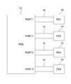
도 1은 본 발명의 PoE 시스템을 도시하는 도면이다.1 is a diagram illustrating a PoE system of the present invention.
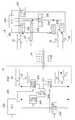
도 2는 본 발명의 제1 바람직한 실시예를 도시하는 도면이다.2 is a diagram showing a first preferred embodiment of the present invention.
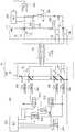
도 3a는 본 발명의 제2 바람직한 실시예를 도시하는 도면이다.3A is a diagram showing a second preferred embodiment of the present invention.
도 3b는 본 발명의 제3 바람직한 실시예를 도시하는 도면이다.3B is a diagram showing a third preferred embodiment of the present invention.
도 3c는 본 발명의 제4 바람직한 실시예를 도시하는 도면이다.Fig. 3C shows a fourth preferred embodiment of the present invention.
도 4는 본 발명의 제5 바람직한 실시예를 도시하는 도면이다.4 is a diagram showing a fifth preferred embodiment of the present invention.
도 5는 본 발명의 제6 바람직한 실시예를 도시하는 도면이다.5 shows a sixth preferred embodiment of the present invention.
도 6은 본 발명의 제7 바람직한 실시예를 도시하는 도면이다.Fig. 6 shows a seventh preferred embodiment of the present invention.
도 7은 본 발명의 제8 바람직한 실시예를 도시하는 도면이다.Fig. 7 is a diagram showing an eighth preferred embodiment of the present invention.
도 8은 본 발명의 제9 바람직한 실시예를 도시하는 도면이다.8 shows a ninth preferred embodiment of the present invention.
이하, 본 발명이 PoE 시스템에서 케이블 저항치를 결정하는 측정 장치의 예를 이용하여 설명될 것이다. 그러나, 여기서 설명되는 개념들이 케이블을 통해 전력을 제공하는 어느 시스템에나 적용 가능하다는 것이 분명해질 것이다. 예를 들 어, 본 발명의 전력 제공 시스템은 다수의 노드들, 네트워크 허브 및 데이터 통신을 제공하기 위해 상기 네트워크 노드들을 상기 네트워크 허브에 연결하는 통신 케이블링을 구비한 근거리 네트워크 내에서 제공될 수 있다. 상기 네트워크 허브는 상기 통신 케이블링을 통해 부하로 전력을 제공하는 전력 공급 장치를 포함할 수 있다. 본 발명의 측정 장치는 상기 통신 케이블링의 저항치를 결정하기 위해 제공될 수 있다.The invention will now be described using an example of a measuring device for determining cable resistance in a PoE system. However, it will be apparent that the concepts described herein are applicable to any system providing power over a cable. For example, the power delivery system of the present invention may be provided within a local area network having a communication cabling that connects the network nodes to the network hub to provide multiple nodes, a network hub and data communication. . The network hub may include a power supply for providing power to a load through the communication cabling. The measuring device of the present invention may be provided to determine the resistance of the communication cabling.
도 1은 전력 소싱 장치(12)를 포함하는 PoE 시스템(10)을 도시한 단순화된 블록도(block-diagram)이다. 이때, PSE(12)는 전력 기기들(14)(PD1~PD4)에 각각의 링크들을 통해서 접속 가능한 다수의 포트들(Port1~Port4)을 구비하고 있으며, 각각의 링크들은 이더넷 케이블(16) 내의 꼬임 쌍들(twisted pairs) 세트 2개 또는 4개를 이용하여 제공될 수 있다. 비록 도 1에서는 상기 PSE(12)의 포트들 4개를 보여주고 있기는 하지만, 당업자라면 포트들이 얼마든지 제공될 수 있다는 것을 알 수 있을 것이다.1 is a simplified block-diagram illustrating a PoE system 10 that includes a
PSE(12)는 IEEE 802.3af 표준에 따라서 각각의 PD와 상호작용할 수 있다. 특히, PSE(12) 및 PD는 PSE(12)가 PD를 검출하기 위해 링크를 탐침(probe)하는 상기 PD 검출 과정에 참여할 수 있다. 이때, PD가 검출되는 경우, PSE(12)는 이것이 유효인 지 무효인 지를 결정하기 위해 PD 검출 시그니쳐를 체크한다. 상기 유효 및 무효 검출 시그니쳐들은 상기 IEEE 802.3af 표준에 정의되어 있다. 상기 유효 PD 검출 시그니쳐가 PD가 전력을 받아들이는 상태에 있다는 것을 나타내는 반면, 상기 무효 PD 검출 시그니쳐는 PD가 전력을 받아들이지 못하는 상태에 있다는 것을 나타 낸다.The
상기 검출 시그니쳐가 유효한 경우, PD는 전원이 켜졌을 때 얼마나 많은 양의 전력을 인출할 지를 나타내기 위해 상기 PSE에게 분류 시그니쳐를 제시하는 옵션을 구비한다. 예를 들어, PD는 등급(class) 0 내지 4로 분류될 수 있다. PD의 결정된 등급에 기초하여, PSE는 필요한 전력을 PD에 인가한다.If the detection signature is valid, the PD has the option of presenting a classification signature to the PSE to indicate how much power to draw when the power is turned on. For example, PDs can be classified as classes 0-4. Based on the determined rating of the PD, the PSE applies the required power to the PD.
도 2에 도시된 바와 같이, 전력은 PSE(12)의 포트 각각을 각각의 PD(14)에 연결하는 이더넷 케이블(16)의 4개의 꼬임 쌍들에 의해 인가될 수 있다. PSE(12)는 트랜스포머들(20, 22, 24, 26)을 이용하여 케이블(16) 내의 4개의 와이어 꼬임 쌍들에 커플링될 수 있다. 이때, 트랜스포머들(20, 22, 24, 26)은 각각의 꼬임 쌍들 및 이더넷 네트워크 내에서 데이터 통신을 제공하도록 정렬된 이더넷 물리적 계층(이하, PHY: physical layer) 기기들 사이에서 커플링된다. PD 측에서, PD(14)는 각각의 꼬임 쌍들 및 이더넷 물리적 계층 기기들 사이에서 연결되는 트랜스포머들(30, 32, 34, 36)을 이용하여 케이블(16) 내의 4개의 와이어 꼬임 쌍들에 커플링될 수 있다. IEEE 802.3af 표준에서 정의된 상기 PoE 인터페이스(interface)는 PSE(12) 및 PD(14)를 이더넷 케이블(16)에 연결하는 데 이용될 수 있다.As shown in FIG. 2, power may be applied by four twisted pairs of
케이블(16)에 대한 PoE 인터페이스는 PD 및 PSE의 섀시(chassis) 양쪽으로부터 전기로 분리되고, 따라서 지상으로부터 분리된다. 그러므로 케이블(16)을 통해 전류를 제공하는 것은 케이블을 통한 전송로(send path) 및 반송로(return path)를 포함한다. 통상적으로, 2개의 꼬임 쌍들은 PSE(12)로부터 PD(14)로 전력을 공급하는 데 함께 이용되는데, 한 쌍은 전송로로, 다른 한 쌍은 반송로로 이용된다.The PoE interface to the
PSE(12)는 케이블(16)의 DC 저항치를 결정하는 측정 장치(200)를 포함할 수 있다. 이때, 상기 측정 장치(200)는 제어 회로(202), 시그날링 회로(204), 전류 구동 회로(206), 전압 측정 회로(208) 및 멀티플렉싱 스위치들(multiplexing switches)(210, 212)을 포함한다. 상기 회로들(204, 206)은 외부(outer) 와이어 꼬임 쌍들에 연결된 상기 트랜스포머들(20, 26) 사이에서 커플링될 수 있다. 상기 멀티플렉싱 스위치들(210, 212)은 상기 전압 측정 회로(208)를 상기 외부 꼬임 쌍들에 연결된 상기 트랜스포머들(20, 26) 또는 상기 내부(inner) 와이어 꼬임 쌍들에 연결된 상기 트랜스포머들(22, 24)에 연결시킬 수 있다.
케이블 저항치 측정 과정을 지원하기 위해, PD(14)는 제어 회로(220), 신호 수신기(signal receiver)(222), 분로 레귤레이터(224) 및 스위치들(226, 228, 230, 232)을 포함할 수 있다. 신호 수신기(222)는 외부 꼬임 쌍들에 연결된 상기 트랜스포머들(30, 36)에 커플링될 수 있다. 스위치들(226, 228, 230, 232)은 각각 분로 레귤레이터(224)를 트랜스포머들(30, 32, 34, 36)에 연결할 수 있다. 예를 들어, MOSFET들은 상기 스위치들(226~232)처럼 이용될 수 있다.To support the cable resistance measurement process, the
제어 회로들(202, 220)은 케이블 저항치 측정 과정에 포함된 PSE 및 PD 회로들을 각각 제어할 수 있다. 특히, 제어 회로(202)는 PD에 케이블 저항치 측정 과정이 개시되었음을 알려주는 표시 신호를 생성하기 위해 시그날링 회로(204)를 제어할 수 있다. 표시 신호는 제어 회로(220)에 각각의 신호를 제공하는 신호 수신기(222)에 의해서 수신된다. 표시 신호에 응답하여, 제어 회로(220)는 분로 레귤레이터(224)를 트랜스포머들(30, 32, 34, 36)을 통해 각각의 꼬임 쌍들에 연결하기 위해 스위치들(226, 228, 230, 232)을 폐쇄한다.The
표시 신호의 생성 후, 제어 회로(202)는 측정 중인 꼬임 쌍들 위에(onto) 소정의 값 I의 전류를 구동하기(force) 위해 전류 구동 회로(206)를 제어한다. 예를 들어, 도 1은 트랜스포머들(20, 26)에 연결된 외부 꼬임 쌍들의 DC 저항치가 결정되는 경우를 도시한다. 따라서, 상기 소정의 전류 I는 외부 꼬임 쌍들 위에(onto) 구동된다. 추후 좀더 자세히 논의되겠지만, 측정 장치(100)는 다른 꼬임 쌍들의 저항치와 독립적으로 각각의 꼬임 쌍의 저항치를 결정하기 위해 모든 가능한 꼬임 쌍들 조합의 DC 저항치를 결정할 수 있다.After generation of the display signal, the
구동된 소정의 전류 I는 PD 측에서 상기 외부 꼬임 쌍들 사이의 일정한 입력 전압 VIN을 생성하는 분로 레귤레이터(224)를 통해 전류가 흐르도록 한다. 모든 스위치들(226~232)이 폐쇄되면, 입력 전압 VIN은 트랜스포머들(32, 34)에 연결된 내부 꼬임 쌍들 사이에서도 생성된다.The predetermined current I driven causes current to flow through the
제어 회로(202)는 전압 측정 회로(208)가 PSE 측에서 외부 꼬임 쌍들 사이의 전압 V1을, PSE 측에서 내부 꼬임 쌍들 사이의 전압 V2를 측정할 수 있도록 멀티플렉싱 스위치들(210, 212)을 제어한다. 전압 V2는 PD 측에서 내부 꼬임 쌍들 사이에서 생성된 전압 VIN과 동일하다.The
이러한 전압 측정에 기초하여, 제어 회로(202)는 외부 꼬임 쌍들의 왕복 DC 저항치인 R을 R = (V1- V2)/I와 같이 결정할 수 있다.Based on this voltage measurement, the
도 2의 배열은 케이블(16) 내의 어느 와이어 꼬임 쌍의 DC 저항치를 결정하도록 수정될 수 있다. 특히, 도 3a는 본 발명의 한 실시예를 도시하는데, 도 2에서 보여진 상기 소자들에 추가하여, 케이블(16)의 DC 저항치를 결정하는 측정 장치(300)는 각각 1개의 입력(input)과 4개의 출력(output)들을 구비한 4개의 멀티플렉싱 스위치들(302, 304, 306, 308)을 더 포함한다. 멀티플렉싱 스위치들(302, 304, 306, 308) 각각은 꼬임 쌍들의 모든 가능한 조합의 왕복 DC 저항치를 결정하기 위한 상기 제어 회로(202)에 의해 제어될 수 있다.The arrangement of FIG. 2 can be modified to determine the DC resistance of any wire twist pair in
위에서 도 2와 관련하여 논의되었듯이, 외부 꼬임 쌍들의 왕복 DC 저항치를 결정하기 위해, 전류 구동 회로(206)는 멀티플렉싱 스위치들(302, 308)을 통해 외부 꼬임 쌍들에 상응하는 트랜스포머들(20, 26)에 연결될 수 있다. 결과적으로, 전류 구동 회로(206)는 소정의 전류 I를 외부 꼬임 쌍 위에 구동하도록 인에이블될(enable) 수 있다. 게다가, 소정의 전류가 그 위에 구동된 꼬임 쌍들 사이에서 전압 V1을 측정하기 위해 전압 측정 회로(208)는 스위치들(210, 302)에 의해 트랜스포머(20)에 커플링된 외부 꼬임 쌍에 연결될 수 있고, 스위치들(212, 308)에 의해 트랜스포머(26)에 커플링된 외부 꼬임 쌍에 연결될 수 있다. PD(14)의 입력 전압 VIN에 상응하는 전압 V2를 측정하기 위해 전압 측정 회로(208)는 스위치들(210, 304)에 의해 트랜스포머(22)에 커플링된 내부 꼬임 쌍에 연결될 수 있고, 스위치들(212, 306)에 의해 트랜스포머(24)에 커플링된 내부 꼬임 쌍에 연결될 수 있다.As discussed in connection with FIG. 2 above, in order to determine the reciprocating DC resistance of the outer twisted pairs, the
비슷한 방식으로, 전류 구동 회로(206)는 소정의 전류를 그 꼬임 쌍들 위에 구동하도록 측정 중인 어느 2개의 꼬임 쌍들에 연결될 수 있고, 전압 측정 회로(208)는 그 꼬임 쌍들 사이의 전압 V1을 결정하기 위해동일한 2개의 꼬임 쌍들에 연결될 수 있고, 그 꼬임 쌍들 사이의 전압 V2를 결정하기 위해 다른 2개의 꼬임 쌍들에 연결될 수도 있다.In a similar manner, the
따라서, 꼬임 쌍들(A, B, C, D)로 이루어진 케이블에서 측정 장치(300)는 상술된 방식으로, 꼬임 쌍들(A, B), 꼬임 쌍들(A, C), 꼬임 쌍들(A, D), 꼬임 쌍들(B, C), 꼬임 쌍들(B, D), 꼬임 쌍들(C, D)의 왕복 DC 저항치 R을 결정할 수 있다. 이 왕복 저항치들에 기초하여, 제어 회로(202)는 각각의 개별적인 꼬임 쌍(A, B, C 또는 D)의 DC 저항치를 케이블 내의 다른 꼬임 쌍들의 저항치와 독립적으로 결정할 수 있다.Thus, in the cable consisting of twist pairs A, B, C, D, the measuring
도 3b는 도 3a와 유사한 배열을 보여준다. 하지만, PD(14)는 스위치 소자들(switch elements)(226, 228, 230, 232) 대신 다이오드 브리지들(diode bridges)(312, 314)을 사용한다. 다이오드 브리지들(312, 314)의 사용은 802.3af PD들에서 전형적인 것이다. 브리지들 내에서의 다이오드들의 극성(polarity) 때문에, PD(14)는 측정 중인 꼬임 쌍으로부터 측정되고 있지 않은 꼬임 쌍 위에 입력 전압 VIN의 카피(copy)를 인가할 수가 없다. 이를 보상하기 위해서, PSE(12)는 이제 제2 전류 구동 회로(316)를 포함한다. 이 회로는 측정되고 있지 않은 꼬임 쌍들 위에 매우 적은 양의 전류를 인가하는데, 이는 케이블에 대해 많은 전압 강하(drop)를 일으킬 것 같지는 않다. VIN의 복사(replica)가 이제 측정되고 있지 않은 꼬임 쌍들 위에 있어서 이 적은 양의 전류는 브리지 내에서 바이어스(biases) 다이오드들을 전송한다. 다른 모든 방법들에서, 측정은 도 3a를 위해 설명된 것처럼 진행한다.FIG. 3B shows an arrangement similar to FIG. 3A. However,
다이오드 브리지들(312, 314)의 추가는 케이블 저항치 측정을 한층 복잡하게 만든다. 이는 다이오드 브리지들의 다이오드들에 대한 포워드 전압(forward voltage)과 관련된 것으로, 실리콘 다이오드들에 있어 포워드 전압은 보통 0.6V이지만 온도에 따라 변한다. 다이오드들이 물리적으로 아주 근접하여 놓인다면, 다이오드들은 거의 같은 온도, 따라서 거의 같은 전압 강하를 갖게 될 것이다. 다이오드들에 대한 전압 강하에 있어 유일한 차는 다이오드들을 통해 흐르는 전류 차에 기인할 것이다. 따라서, 다이오드 저항치는 측정된 케이블 저항치에 통합될 것이다.The addition of
여기서 설명된 모든 케이블 저항치 측정 방법들에 있어서, 다이오드 브리지들이 PD 내에서 보여지지 않고, PSE 내에서 적은 전류 소스가 보여지지 않기는 하지만, 이 소자들의 추가는 PD 내에서 다이오드들의 극성에 의해 달리 차단되는 PD로부터 어느 방법들이라도 전압을 다시 읽는 것을 허용할 것이라는 점이 주목된다.In all the cable resistance measurement methods described herein, the addition of these devices is otherwise blocked by the polarity of the diodes in the PD, although diode bridges are not seen in the PD and a small current source is not seen in the PSE. It is noted that any method from the PD that will be allowed to reread the voltage.
PSE가 사용할 수 있는 도 3a 측정 방법의 또 다른 실시예는 케이블에 대해 상대적으로 큰 전압 강하를 생성하도록 고안된 큰 값 및 케이블에 대해 매우 적은 전압 강하를 생성하도록 고안된 상대적으로 작은 값 사이에서 전류 구동 회로의 전류를 바꾸는 것이다. 도 3c는 이와 같은 작용을 하는 조절 가능한 전류 구동 회로(320)를 포함하는 PSE(12)를 보여준다. PSE(12)가 한 번에 2개의 와이어 쌍들에 연결되는 것만을 필요로 한다는 것이 주목된다. 그러므로, 도 3c 배열에서, PSE(12)는 도 3a 및 3b에서 보여진 4개의 스위치들(302, 304, 306, 308) 대신 2개의 스위치들(322, 324)만을 포함한다. PSE의 출력에서 이 2개의 다른 전류들로 전압을 측정하는 것은 상술한 바와 같은 효과를 갖는다. 높은 전류에서의 전압은 V1이고, 낮은 전류에서의 전압은 V2이다. 이 전압들을 같은 R = (V1- V2)/I 등식에 입력하면 케이블 저항치가 나온다. 방금 언급했듯이, PD(14) 내에서 다이오드들의 저항치 또한 결과로 도출된 저항치 R 안에 포함된다.Another embodiment of the FIG. 3A measurement method that a PSE can use is a current drive circuit between a large value designed to produce a relatively large voltage drop over a cable and a relatively small value designed to produce a very small voltage drop over the cable. To change the current. 3C shows a
상술된 측정 과정들의 정확도는 PSE 내의 회로 소자에 의해 직접적으로 측정되는 전압들 V1및 V2에 달려 있다. 이는 PSE에 연결된 특정 PD의 파라미터들(parameters)에 의존하는 것을 회피한다. 하지만, V1및 V2의 동시 측정은 이더넷 케이블 내의 모든 와이어들을 이용한다. 그리고 이 측정에 필수적인 전압들과 전류들을 통과하도록 스위치들(226~232)을 확실히, 그리고 저가로 만드는 것은 어려운 일일 수 있다. 도 3b 및 3c 내의 다이오드 브리지들의 이용은 스위치 문제를 해결한다. PSE의 구동 전류(도 3c)는 조절하면서 모든 쌍들을 동시에 이용할 필요성은 제거한다.The accuracy of the measurement procedures described above is based on the voltages V1 measured directly by the circuit element in the PSE. And V2 . This avoids depending on the parameters of the particular PD connected to the PSE. But V1 Simultaneous measurement of and V2 uses all wires in the Ethernet cable. And it can be difficult to make the switches 226-232 low and low enough to pass the voltages and currents necessary for this measurement. The use of diode bridges in FIGS. 3B and 3C solves the switch problem. The drive current of the PSE (Figure 3c) is adjusted while eliminating the need to use all pairs simultaneously.
도 4는 PD(14)가 전압 V2를 PSE(12)로 되돌려 보내는 과정을 이용하는 이더넷 케이블(16) 내의 2개의 꼬임 쌍들의 DC 저항치를 결정하기 위한 측정 장치(400)를 도시한다. 이는 스위치들(226~232) 및 이더넷 케이블 내의 모든 와이어들의 동 시 사용의 필요성을 제거한다. 예를 들어, 도 4는 PSE 측에서 트랜스포머들(22, 24)에 커플링되고, PD 측에서 트랜스포머들(32, 34)에 커플링되는 꼬임 쌍들의 DC 저항치의 측정을 도시한다. PSE(12) 내의 측정 장치(400)는 트랜스포머들(22, 24) 사이에 연결된 전류 구동 회로(404) 및 전압 측정 회로(406)를 제어하는 제어 회로(402)를 포함할 수 있다. 측정을 지원하기 위해, PD(14)는 트랜스포머들(32, 34) 사이에 연결된 부하 회로(412), 샘플 및 홀드 회로(414) 및 드라이브 회로(416)를 제어하는 제어 회로(410)를 포함할 수 있다.4 shows a
측정 과정은 전류 구동 회로(404)가 PSE(12)의 단자들을 통해 꼬인 와이어들 위에 구동된 소정의 전류 I를 생성하도록 제어하는 제어 회로(402)에 의해 개시된다. PD(14)의 단자들 사이에 연결된 부하 회로(412)로 공급되는 소정의 전류 I는 단자들 사이에서 입력 전압 VIN을 야기한다. 예를 들어, 부하 회로(412)는 저항 또는 PD(14)의 말단들 사이의 임피던스(impedance)를 일으키는 어느 다른 회로가 될 수 있다.The measurement process is initiated by the
입력 전압 VIN이 고정되면, 제어 회로(410)는 이 전압을 획득하기 위해 샘플 및 홀드 회로(414)를 제어한다. 동시에, 제어 회로(402)는 이 단자들 사이의 전압 V1을 측정하기 위해 PSE(12)의 단자들 사이에 연결된 전압 측정 회로(406)를 제어한다.When the input voltage VIN is fixed, the
그 후에, 제어 회로(402)는 전류 I가 케이블(16)을 통해 흐르는 것을 방지하기 위해 전류 구동 회로(404)를 턴 오프한다. 응답으로, 제어 회로(410)는 샘플 및 홀드 회로(414)에 의해 획득된 전압 VIN을 케이블(16) 위로 구동(drive)하기 위한 드라이브 회로(416)를 제어한다. MOSFET 회로 같은 스위칭 회로는 드라이브 회로(416)처럼 사용될 수 있다.Thereafter, the
PSE 측에서, 전압 측정 회로(406)는 전압 VIN에 상응하는 전압 V2를 측정하고, 제어 회로(402)는 꼬임 쌍들의 왕복 DC 저항치 R을 R = (V1- V2)/I와 같이 계산한다.On the PSE side, the
도 4 내의 배열은 또 다른 꼬임 쌍의 저항치와 독립적으로 어느 꼬임 쌍의 개별적인 DC 저항치를 결정하기 위해 수정될 수 있다. 특히, 도 5는 본 발명의 한 실시예를 도시하는데, 여기서 도 4에서 보여진 소자들에 덧붙여, 케이블(16)의 DC 저항치를 결정하는 측정 장치(500)는 PSE 측에 제공된 2개의 멀티플렉싱 스위치들(502, 504)을 더 포함한다. 더욱이, 2개의 멀티플렉싱 스위치들(512, 514)은 PD 측에도 제공될 수 있다. 멀티플렉싱 스위치들(502, 504, 512, 514) 각각은 1개의 입력 및 4개의 출력들을 구비할 수 있다. 멀티플렉싱 스위치들(502, 504)은 제어 회로(402)에 의해 제어될 수 있는 반면, 멀티플렉싱 스위치들(512, 514)은 제어 회로(410)에 의해 제어될 수 있다.The arrangement in FIG. 4 can be modified to determine the individual DC resistance of any twist pair independently of the resistance of another twist pair. In particular, FIG. 5 shows an embodiment of the present invention, wherein in addition to the elements shown in FIG. 4, the measuring
각각의 제어 회로들은 케이블(16) 내에서 4개의 꼬임 쌍들의 모든 가능한 조합의 저항치를 결정하기 위해 스위치들(502, 504, 512, 514)을 제어할 수 있다. 도 5가 도형의 명확성(clarity)을 유지하기 위해 4개의 꼬임 쌍들의 연결을 보여주지는 않지만, 당업자라면 꼬임 쌍들이 도 2의 배열과 유사한 방식으로 PSE(12) 및 PD(14)에 연결될 수 있음을 알 수 있을 것이다.Each control circuit can control the
꼬임 쌍들(A, B, C, D)을 포함하는 케이블 내에서 선택된 2개의 꼬임 쌍들(A, B)의 왕복 DC 저항치를 결정하기 위해서, 제어 회로(402)는 선택된 꼬임 쌍들(A, B)에 대해 전류 구동 회로(404) 및 전압 측정 회로(406)를 연결하기 위해 스위치들(502, 504)을 제어한다. 또한, 스위치들(512, 514)은 상기 동일한 선택된 꼬임 쌍들(A, B)에 대해 부하 전류(412), 샘플 및 홀드 회로(414) 및 드라이브 회로(416)를 연결할 수 있다. 선택된 꼬임 쌍들(A, B)의 왕복 DC 저항치는 도 4와 관련되어 위에 설명된 방식으로 결정될 수 있다.To determine the reciprocating DC resistance of the two selected twist pairs A, B in the cable comprising the twist pairs A, B, C, D, the
그 후에, 제어 회로들은 위에 설명된 방식으로 꼬임 쌍들 각각의 왕복 DC 저항치를 결정하도록 꼬임 쌍들(A, C), (A, D), (B, C), (B, D) 및 (C, D)에 대하여 각각의 소자들을 성공적으로 연결하기 위해 스위치들을 제어할 수 있다. 이 왕복 저항치들에 기초하여, 제어 회로(402)는 케이블 내의 다른 꼬임 쌍들의 저항치와 독립적으로 각각의 개별적인 꼬임 쌍들(A, B, C 또는 D)의 DC 저항치를 결정할 수 있다.The control circuits are then twisted pairs (A, C), (A, D), (B, C), (B, D) and (C, For D) the switches can be controlled to successfully connect the respective elements. Based on these round trip resistances, the
도 6은 이더넷 케이블(16) 내의 2개의 꼬임 쌍들의 DC 저항치를 결정하는 장치의 또 다른 바람직한 실시예를 도시한다. 예를 들어, 도 6에서 보여지는 꼬임 쌍들은 PSE 측에서 트랜스포머들(22, 24)에 커플링되고, PD 측에서 트랜스포머들(32, 34)에 커플링된다. PSE(12) 내의 측정 장치(600)는 트랜스포머들(22, 24) 사이에서 연결되는 전류 구동 회로(604) 및 전압 측정 회로(606)를 제어하는 제어 회로(602)를 포함할 수 있다. 측정을 지원하기 위해, PD(14)는 정밀 분할기(precision divider)(612)를 제어하는 제어 회로(610), 분로 레귤레이터(614), 기준 회로(616) 및 드라이브 회로(618)를 포함할 수 있다.FIG. 6 shows another preferred embodiment of the apparatus for determining the DC resistance of two twisted pairs in
측정 과정은 PSE(12)의 단자들에 의해 꼬인 와이어들 위에 구동되는 소정의 전류 I를 생성하기 위한 전류 구동 회로(404)를 제어하는 제어 회로(602)에 의해 개시된다. 소정의 전류 I에 응답하여, 제어 회로(620)는 케이블(16)의 PD 측에서 꼬임 쌍들 사이에 생성된 입력 전압 VIN의 소정의 분수(fraction) 1/N을 제공하기 위해 정밀 디바이더(612)를 제어한다.The measurement process is initiated by the
분로 레귤레이터(614)는 오류 증폭기(error amplifier)(620) 및 출력 MOSFET 드라이버(622)를 포함한다. 오류 증폭기(620)는 정밀 분할기(612)에 의해 생성된 전압 VIN/N을 기준 회로(616)의 출력에서 제공되는 소정의 기준 전압 VREF과 비교한다. 결과적으로, 입력 전압 VIN = N x VREF은 분로 레귤레이터(614)의 출력에서 산출된다.
제어 회로(602)는 케이블(16)의 PSE 측에서 전압 V1을 측정하기 위해 전압 측정 회로(606)를 제어한다. 이 측정 동안, 분로 레귤레이터(614)는 전압을 그 출력에서 VIN = N x VREF과 같이 유지한다. 동시에, PD(14)는 에너지 저장 회로(energy storage circuit)(보여지지 않은)를 공급하기 위해 PD(14)를 통해 얼마간의 전류 흐름을 사용할 수 있다.The
그리고 나서, 제어 회로(602)는 전류 I가 케이블(16)을 통해 흐르는 것을 막 기 위해 전류 구동 회로(604)를 턴 오프(turn off)한다. 이에 응답하여, 제어 회로(610)는 분로 레귤레이터(614)를 턴 오프한다.The
그 후에, 제어 회로(610)는 기준 회로(616) 및 드라이브 회로(618)의 공급에 에너지 저장 회로 내에 축적된 전력을 제공한다. MOSFET 회로처럼 스위칭 회로가 될 수 있는 드라이브 회로(618)는 기준 전압 VREF을 꼬임 쌍들 위에 적용한다.Thereafter, the
제어 회로(602)는 PSE 측에서 꼬임 쌍들 사이의 전압을 측정하기 위해 전압 측정 회로(606)를 제어한다. 이 전압은 기준 전압 VREF과 동일하다. 이 측정이 완료되면, 제어 회로(602)는 꼬임 쌍들의 왕복 저항치 R을 R = (V1- VREF× N)/I과 같이 결정한다.The
도 6의 배열은 또 다른 꼬임 쌍의 저항치와 독립적으로 어느 꼬임 쌍의 개별적인 DC 저항치를 결정하기 위해 수정될 수 있다. 특히, 도 7은 본 발명의 한 실시예를 도시하는데, 여기서 도 6에 보여진 소자들에 추가하여, 케이블(16)의 DC 저항치를 결정하기 위한 측정 장치(700)는 PSE 측 위에 제공된 2개의 멀티플렉싱 스위치들(702, 704)을 더 포함한다. 또한, 2개의 멀티플렉싱 스위치들(712, 714)은 PD 측 위에 제공될 수 있다. 각각의 멀티플렉싱 스위치들(702, 704, 712, 714)은 1개의 입력 및 4개의 출력을 구비할 수 있다. 멀티플렉싱 스위치들(702, 704)은 제어 회로 (602)에 의해 제어되는 반면, 멀티플렉싱 스위치들(712, 714)은 제어 회로(610)에 의해 제어될 수 있다.The arrangement of FIG. 6 can be modified to determine the individual DC resistance of any twist pair independently of the resistance of another twist pair. In particular, FIG. 7 shows one embodiment of the present invention wherein in addition to the elements shown in FIG. 6, a measuring
각각의 제어 회로들은 케이블(16) 내의 4개의 꼬임 쌍들의 모든 가능한 조합 의 저항치를 결정하기 위해 스위치들(702, 704, 712, 714)을 제어할 수 있다. 도 7이 도형의 명확성을 유지하기 위해 4개의 꼬임 쌍들의 연결을 보여주지는 않지만, 당업자라면 꼬임 쌍들이 도 2의 배열과 유사한 방식으로 PSE(12) 및 PD(14)에 연결될 수 있음을 알 수 있을 것이다.Each control circuit can control the
꼬임 쌍들(A, B, C, D)을 포함하는 케이블 내에서 선택된 2개의 꼬임 쌍들(A, B)의 왕복 DC 저항치를 결정하기 위해서, 제어 회로(602)는 선택된 꼬임 쌍들(A, B)에 대해 전류 구동 회로(604) 및 전압 측정 회로(606)를 연결하기 위해 스위치들(702, 704)을 제어한다. 또한, 스위치들(712, 714)은 상기 동일한 선택된 꼬임 쌍들(A, B)에 대해 상기 PD 케이블 측정 회로 소자를 연결할 수 있다. 선택된 꼬임 쌍들(A, B)의 왕복 DC 저항치는 도 6과 관련되어 위에 설명된 방식으로 결정될 수 있다.To determine the reciprocating DC resistance of the two selected twist pairs A, B in the cable comprising the twist pairs A, B, C, D, the
그 후에, 제어 회로들은 위에 설명된 방식으로 이 꼬임 쌍들 각각의 왕복 DC 저항치를 결정하도록 꼬임 쌍들(A, C), (A, D), (B, C), (B, D) 및 (C, D)에 대하여 각각의 PSE 및 PD 케이블 측정 회로 소자들을 성공적으로 연결하기 위해 스위치들을 제어할 수 있다. 이 왕복 저항치들에 기초하여, 제어 회로(602)는 케이블 내의 다른 꼬임 쌍들의 저항치와 독립적으로 각각의 개별적인 꼬임 쌍(A, B, C 또는 D)의 DC 저항치를 결정할 수 있다.The control circuits are then twisted pairs A, C, (A, D), (B, C), (B, D) and (C) to determine the reciprocating DC resistance of each of these twisted pairs in the manner described above. For D), switches can be controlled to successfully connect the respective PSE and PD cable measurement circuit elements. Based on these round trip resistances, the
게다가, 도 2~7 내의 배열들은 8-와이어 케이블 내의 와이어 각각의 DC 저항치를 측정하기 위해 수정될 수 있다. 도 8에서 보여진 것처럼, 케이블(16) 내의 꼬임 쌍을 연결하는 데 쓰이는 각각의 트랜스포머는 꼬임 쌍 내의 2개의 와이어들에 상응하는 2개의 와인딩들로 분할될 수 있다. 도형의 명확성을 유지하기 위해, PSE 측 위의 트랜스포머(22) 및 PD 측 위의 트랜스포머(32)만이 보여진다. 그러나, 당업자라면 도 2에서 보여진 다른 트랜스포머들도 같은 방식으로 배열될 수 있음을 알 것이다.In addition, the arrangements in FIGS. 2-7 can be modified to measure the DC resistance of each wire in the 8-wire cable. As shown in FIG. 8, each transformer used to connect a twisted pair in
커패시터(capacitor)(C)는 이더넷 데이터를 위한 AC로(path)를 제공하되 DC 전류가 와인딩들을 통해 흐르는 것을 방지하기 위한 각각의 트랜스포머의 분할 와인딩들 사이에 연결될 수 있다. 그러므로, 각각의 꼬임 쌍 내부의 와이어들은 더 이상 서로 DC 접속된 것이 아니다. 따라서, 와이어 각각의 DC 저항치는 개별적으로 측정될 수 있다.Capacitor C may be connected between the split windings of each transformer to provide an AC path for Ethernet data but to prevent DC current from flowing through the windings. Therefore, the wires within each twisted pair are no longer DC connected to each other. Thus, the DC resistance of each wire can be measured individually.
트랜스포머들(80, 82)에 의해, 트랜스포머들(22, 32)은 멀티플렉싱 스위치들(84, 86)의 출력들에 커플링될 수 있다. 멀티플렉싱 스위치들(84, 86) 각각은 PSE 케이블 측정 회로 소자 및 PD 케이블 측정 회로 소자를 케이블(16)의 8개의 와이어들 사이에서 선택된 한 와이어에 연결하기 위한 1개의 입력 및 4개의 출력들을 구비한다. 또 다른 한 쌍의 유사한 멀티플렉싱 스위치들(보여지지 않은)은 PSE 케이블 측정 회로 소자 및 PD 케이블 측정 회로 소자를 또 다른 선택된 와이어에 연결하도록 제공될 수 있다.By
도 2~7과 관련되어 위에 설명된 케이블 측정 과정들의 어떤 한 과정과 유사한 방식으로 와이어들의 조합 각각의 왕복 DC 저항치를 결정하기 위해 각각의 PSE 및 PD 케이블 측정 회로 소자들을 케이블 내 각각의 와이어에 성공적으로 연결하도록 PSE(12) 내의 제어 회로는 PSE 내의 멀티플렉싱 스위치들 각각을 제어할 수 있 고, PD(14) 내의 제어 회로는 PD 내의 멀티플렉싱 스위치들을 제어할 수 있다. 결과로, 본 발명의 케이블 측정 장치는 다른 와이어들의 저항치와 독립적으로 와이어 각각의 DC 저항치를 결정할 수 있다. 당업자라면 알 수 있듯이, 도 8에서 보여진 수정은 예를 들어, 도 2, 4 및 6에 보여진 배열들 같은 케이블 저항치 측정 배열들 어느 것에든 적용 가능하다.Successfully connect each PSE and PD cable measurement circuitry to each wire in the cable to determine the reciprocal DC resistance of each combination of wires in a manner similar to any one of the cable measurement procedures described above in connection with FIGS. The control circuitry in the
상술한 기재에서 본 발명의 측면들을 도시하고 설명하였다. 부가적으로, 본 발명은 바람직한 실시예들만을 도시하고 설명하고 있지만, 상술한 바와 같이, 본 발명이 속하는 분야에서 통상의 지식을 가진 자라면 이러한 기재로부터 본 발명의 범위를 벗어나지 않는 범위 내에서 다양한 수정 및 변형이 가능하다.The aspects of the invention have been illustrated and described in the foregoing description. Additionally, while the present invention has been shown and described with respect to preferred embodiments only, it will be understood by those skilled in the art that various changes in form and details may be made therein without departing from the spirit and scope of the invention as defined by the appended claims. Modifications and modifications are possible.
상술한 실시예들은 본 발명을 실행하는 데 있어서 알려진 바람직한 실시예들을 설명하고, 당업자라면 본 발명의 특정한 적용 또는 사용들에 의해서 요구되는 그러한 또는 다른 실시예들을 포함하며 다양한 변형이 가능한 발명을 이용하도록 의도된다.The above-described embodiments describe preferred embodiments known in practicing the present invention, and those skilled in the art can utilize the invention in various modifications, including those or other embodiments required by the specific application or uses of the present invention. It is intended.
그러므로, 본 발명의 범위는 설명된 실시예에 국한되어 정해져서는 아니 되며, 후술하는 특허청구범위뿐만 아니라 이 특허청구범위와 균등한 것들에 의해 정해져야 한다.Therefore, the scope of the present invention should not be limited to the described embodiments, but should be determined not only by the claims below but also by the equivalents of the claims.
Claims (37)
Translated fromKoreanApplications Claiming Priority (5)
| Application Number | Priority Date | Filing Date | Title |
|---|---|---|---|
| US64650905P | 2005-01-25 | 2005-01-25 | |
| US60/646,509 | 2005-01-25 | ||
| US11/334,456US7511515B2 (en) | 2005-01-25 | 2006-01-19 | System for providing power over communication cable having mechanism for determining resistance of communication cable |
| US11/334,456 | 2006-01-19 | ||
| PCT/US2006/002242WO2006081167A2 (en) | 2005-01-25 | 2006-01-23 | System for providing power over communication cable having mechanism for determining resistance of communication cable |
Publications (2)
| Publication Number | Publication Date |
|---|---|
| KR20070102559A KR20070102559A (en) | 2007-10-18 |
| KR101224712B1true KR101224712B1 (en) | 2013-01-21 |
Family
ID=36696116
Family Applications (1)
| Application Number | Title | Priority Date | Filing Date |
|---|---|---|---|
| KR1020077018920AActiveKR101224712B1 (en) | 2005-01-25 | 2006-01-23 | System for Providing Power over Communication Cable Having Mechanism for Determining Resistance of Communication Cable |
Country Status (5)
| Country | Link |
|---|---|
| US (1) | US7511515B2 (en) |
| EP (1) | EP1842329B1 (en) |
| JP (1) | JP4718562B2 (en) |
| KR (1) | KR101224712B1 (en) |
| WO (1) | WO2006081167A2 (en) |
Families Citing this family (56)
| Publication number | Priority date | Publication date | Assignee | Title |
|---|---|---|---|---|
| US7478251B1 (en)* | 2004-12-23 | 2009-01-13 | Cisco Technology, Inc. | Methods and apparatus for provisioning uninterruptible power for power over Ethernet applications |
| US7693076B2 (en)* | 2005-02-15 | 2010-04-06 | Cisco Technology, Inc. | Detection algorithm for delivering inline power down four pairs of an ethernet cable to a single powered device |
| US7761719B2 (en)* | 2005-03-28 | 2010-07-20 | Akros Silicon Inc. | Ethernet module |
| US7451329B2 (en)* | 2005-09-08 | 2008-11-11 | Cisco Technology, Inc. | Techniques for measuring network resistive loss within a power-sourcing apparatus |
| US7631201B2 (en) | 2006-05-25 | 2009-12-08 | Foundry Networks, Inc. | System software for managing power allocation to Ethernet ports in the absence of mutually exclusive detection and powering cycles in hardware |
| US7774628B2 (en)* | 2006-05-25 | 2010-08-10 | Foundry Networks, Inc. | Enabling/disabling power-over-ethernet software subsystem in response to power supply status |
| US8576873B2 (en)* | 2006-11-30 | 2013-11-05 | Broadcom Corporation | System and method for controlling power delivered to a powered device based on channel impediments |
| US7664972B2 (en) | 2006-12-19 | 2010-02-16 | Broadcom Corporation | System and method for controlling power delivered to a powered device based on cable characteristics |
| US7417443B2 (en)* | 2007-01-07 | 2008-08-26 | Microsemi Corp. - Analog Mixed Signal Group, Ltd. | Determination of effective resistance between a power sourcing equipment and a powered device |
| US7989976B2 (en) | 2007-01-16 | 2011-08-02 | Broadcom Corporation | System and method for controlling a power budget at a power source equipment using a PHY |
| CN101632256B (en)* | 2007-02-13 | 2014-08-20 | 凌力尔特有限公司 | Measuring cable resistance in system for providing power over communication cable |
| US8250381B2 (en) | 2007-03-30 | 2012-08-21 | Brocade Communications Systems, Inc. | Managing power allocation to ethernet ports in the absence of mutually exclusive detection and powering cycles in hardware |
| US7996698B2 (en)* | 2007-04-05 | 2011-08-09 | Aruba Networks, Inc. | System and method for enabling functionality based on measured power |
| US7818591B2 (en)* | 2007-04-11 | 2010-10-19 | Cisco Technology, Inc. | Techniques for measuring network channel resistive loss between a power-sourcing apparatus and a powered device |
| GB0708443D0 (en)* | 2007-05-02 | 2007-06-06 | Crouch Iain C | Apparatus and method for estimating power losses in data cables |
| US8035359B2 (en)* | 2007-05-07 | 2011-10-11 | Analogix Semiconductor, Inc. | Apparatus and method for recovery of wasted power from differential drivers |
| US9041241B2 (en) | 2007-05-07 | 2015-05-26 | Analogix Semiconductor, Inc. | Systems and methods for powering a charging circuit of a communications interface |
| US8063504B2 (en) | 2007-05-07 | 2011-11-22 | Analogix Semiconductor, Inc. | Systems and methods for powering circuits for a communications interface |
| US8175555B2 (en) | 2007-05-07 | 2012-05-08 | Analogix Semiconductor, Inc. | Apparatus and method for termination powered differential interface periphery |
| US7705741B2 (en)* | 2007-05-21 | 2010-04-27 | Texas Instruments Incorporated | Detection of a broken wire between power sourcing equipment and a powered device |
| US7696765B2 (en)* | 2007-09-03 | 2010-04-13 | Broadcom Corporation | System and method for measuring a cable resistance in a Power over Ethernet application |
| US7902694B2 (en)* | 2007-11-08 | 2011-03-08 | Cisco Technology, Inc. | Dynamic current limits |
| US20100187903A1 (en)* | 2007-12-17 | 2010-07-29 | Wael William Diab | Method and system for vehicular power distribution utilizing power over ethernet in an aircraft |
| US20090152943A1 (en)* | 2007-12-17 | 2009-06-18 | Wael William Diab | Method and system for vehicular power distribution utilizing power over ethernet |
| US20090222678A1 (en)* | 2008-02-29 | 2009-09-03 | Broadcom Corporation | Active powered device for the application of power over ethernet |
| CN101282275B (en)* | 2008-05-23 | 2013-01-30 | 杭州华三通信技术有限公司 | Telecommunication Ethernet system and repeater |
| US8095710B2 (en)* | 2008-06-30 | 2012-01-10 | Silicon Laboratories Inc. | System and method of providing electrical isolation |
| DE102010032513A1 (en)* | 2010-07-28 | 2012-02-02 | Fujitsu Technology Solutions Intellectual Property Gmbh | Energy saving circuit for a network powered device, network arrangement and energy saving method |
| CN102457384A (en)* | 2010-10-28 | 2012-05-16 | 鸿富锦精密工业(深圳)有限公司 | Power supply device |
| NL2006494C2 (en)* | 2011-03-25 | 2012-09-26 | Astrea Intellectueel Eigendomsrecht B V | Isolator device for passing through a signal. |
| AU2012267611B2 (en)* | 2011-06-09 | 2016-11-17 | Commscope Technologies Llc | Distributed antenna system using power-over-ethernet |
| US8779786B2 (en)* | 2011-10-18 | 2014-07-15 | Broadcom Corporation | Remote sensing of PD-side voltage in 4-pair PoE applications for estimating cable resistance |
| US8823402B2 (en) | 2011-11-23 | 2014-09-02 | Broadcom Corporation | Cable resistance determination in high-power PoE networks |
| US9681004B2 (en) | 2012-03-20 | 2017-06-13 | British Telecommunications Public Limited Company | Delivery of electrical power |
| EP2642687A1 (en)* | 2012-03-20 | 2013-09-25 | British Telecommunications public limited company | Delivery of electrical power |
| KR101462719B1 (en)* | 2012-05-31 | 2014-11-17 | 삼성전기주식회사 | COIL COMPONENT, ELECTRIONIC DEVICE AND PoE SYSTEM HAVING THE SAME |
| US9547318B1 (en)* | 2012-10-15 | 2017-01-17 | Linear Technology Corporation | Powered device, using power over ethernet, with dedicated low current and high current paths for loads |
| US9026809B2 (en) | 2012-11-05 | 2015-05-05 | Linear Technology Corporation | Polarity correction bridge controller for combined power over ethernet system |
| US9429534B2 (en)* | 2013-05-16 | 2016-08-30 | Fluke Corporation | Method and apparatus for determining wire resistance |
| WO2014207296A1 (en)* | 2013-06-25 | 2014-12-31 | Ell-I Open Source Co-Operative | A method and device for transmitting' electrical power and data |
| US10712515B2 (en) | 2013-09-17 | 2020-07-14 | Commscope Technologies Llc | Capacitive-loaded jumper cables, shunt capacitance units and related methods for enhanced power delivery to remote radio heads |
| US9759880B2 (en) | 2013-09-17 | 2017-09-12 | Commscope Technologies Llc | Capacitive-loaded jumper cables, shunt capacitance units and related methods for enhanced power delivery to remote radio heads |
| US10830803B2 (en) | 2014-02-17 | 2020-11-10 | Commscope Technologies Llc | Methods and equipment for reducing power loss in cellular systems |
| US9448576B2 (en) | 2014-02-17 | 2016-09-20 | Commscope Technologies Llc | Programmable power supplies for cellular base stations and related methods of reducing power loss in cellular systems |
| US11333695B2 (en) | 2014-02-17 | 2022-05-17 | Commscope Technologies Llc | Methods and equipment for reducing power loss in cellular systems |
| US10281939B2 (en) | 2014-02-17 | 2019-05-07 | Commscope Technologies Llc | Methods and equipment for reducing power loss in cellular systems |
| CN107210921B (en) | 2015-02-17 | 2020-12-29 | 美高森美Poe有限公司 | POE power utilization device and method |
| AU2018215802B2 (en)* | 2017-02-08 | 2022-04-28 | Outdoor Wireless Networks LLC | Methods and equipment for determining conductor resistance |
| WO2018169586A1 (en)* | 2017-03-16 | 2018-09-20 | Commscope Technologies Llc | Methods and appartus for determing cable resistance |
| CN110554725B (en)* | 2018-05-30 | 2021-02-23 | 华为技术有限公司 | Power receiving equipment for power over Ethernet |
| WO2020223452A1 (en) | 2019-05-01 | 2020-11-05 | Commscope Technologies Llc | Methods and equipment for reducing power loss in cellular systems |
| US11994545B2 (en)* | 2021-05-11 | 2024-05-28 | National Instruments Corporation | DC resistance measurement contact checking via alternating current high frequency injection |
| US11558264B1 (en) | 2021-07-09 | 2023-01-17 | ReadyLinks Inc. | Facilitating and provisioning customer broadband transport service |
| EP4367855A1 (en) | 2021-07-09 | 2024-05-15 | Readylinks Inc. | Facilitating and provisioning customer broadband transport service |
| US11750407B2 (en)* | 2021-07-09 | 2023-09-05 | ReadyLinks Inc. | Bidirectional power feed digital communication device |
| WO2025014542A1 (en)* | 2023-07-07 | 2025-01-16 | Amatis Controls Llc | Resistor mapping for device profiles |
Citations (4)
| Publication number | Priority date | Publication date | Assignee | Title |
|---|---|---|---|---|
| KR20070098876A (en)* | 2005-01-25 | 2007-10-05 | 리니어 테크놀러지 코포레이션 | Power distribution control between multiple wires in a communication cable |
| KR20070098875A (en)* | 2005-01-25 | 2007-10-05 | 리니어 테크놀러지 코포레이션 | Adjustment of the current limit threshold based on the output voltage of the power supply in the system for providing power over the communication link |
| KR20070098918A (en)* | 2005-01-25 | 2007-10-05 | 리니어 테크놀러지 코포레이션 | Legacy Power Device Detection in Power Systems over Ethernet |
| KR20070101328A (en)* | 2005-01-25 | 2007-10-16 | 리니어 테크놀러지 코포레이션 | Power supply via four pairs of conductors in a communication cable |
Family Cites Families (10)
| Publication number | Priority date | Publication date | Assignee | Title |
|---|---|---|---|---|
| EP0271969B1 (en)* | 1986-12-19 | 1994-11-30 | Sharp Kabushiki Kaisha | DC power-superposed multiplex transmission system with single parallel cable |
| US5436555A (en)* | 1994-06-09 | 1995-07-25 | Fluke Corporation | LAN cable identifier for testing local area network cables |
| US7612470B2 (en)* | 1999-01-12 | 2009-11-03 | Microsemi Corp.—Analog Mixed Signal Group Ltd. | System for providing power over Ethernet through a patch panel |
| US6473608B1 (en)* | 1999-01-12 | 2002-10-29 | Powerdsine Ltd. | Structure cabling system |
| FR2819364B1 (en)* | 2001-01-08 | 2003-04-11 | Cit Alcatel | DEVICE FOR TELEALING A TERMINAL IN A TELECOMMUNICATION NETWORK, CONCENTRATOR, AND REPEATER COMPRISING SUCH A DEVICE |
| US6483318B1 (en)* | 2001-06-29 | 2002-11-19 | Ideal Industries, Inc. | Electric circuit providing selectable short circuit for instrumentation applications |
| TW200501551A (en) | 2003-04-23 | 2005-01-01 | Rohm Co Ltd | Audio signal amplifier circuit and electronic apparatus having the same |
| US7603570B2 (en)* | 2004-05-13 | 2009-10-13 | Cisco Technology, Inc. | Power delivery over ethernet cables |
| US7903809B2 (en)* | 2004-11-05 | 2011-03-08 | Cisco Technology, Inc. | Power management for serial-powered device connections |
| US7373528B2 (en)* | 2004-11-24 | 2008-05-13 | Cisco Technology, Inc. | Increased power for power over Ethernet applications |
- 2006
- 2006-01-19USUS11/334,456patent/US7511515B2/enactiveActive
- 2006-01-23EPEP06719193Apatent/EP1842329B1/ennot_activeNot-in-force
- 2006-01-23KRKR1020077018920Apatent/KR101224712B1/enactiveActive
- 2006-01-23JPJP2007552331Apatent/JP4718562B2/ennot_activeExpired - Fee Related
- 2006-01-23WOPCT/US2006/002242patent/WO2006081167A2/enactiveApplication Filing
Patent Citations (4)
| Publication number | Priority date | Publication date | Assignee | Title |
|---|---|---|---|---|
| KR20070098876A (en)* | 2005-01-25 | 2007-10-05 | 리니어 테크놀러지 코포레이션 | Power distribution control between multiple wires in a communication cable |
| KR20070098875A (en)* | 2005-01-25 | 2007-10-05 | 리니어 테크놀러지 코포레이션 | Adjustment of the current limit threshold based on the output voltage of the power supply in the system for providing power over the communication link |
| KR20070098918A (en)* | 2005-01-25 | 2007-10-05 | 리니어 테크놀러지 코포레이션 | Legacy Power Device Detection in Power Systems over Ethernet |
| KR20070101328A (en)* | 2005-01-25 | 2007-10-16 | 리니어 테크놀러지 코포레이션 | Power supply via four pairs of conductors in a communication cable |
Also Published As
| Publication number | Publication date |
|---|---|
| US20060164108A1 (en) | 2006-07-27 |
| US7511515B2 (en) | 2009-03-31 |
| WO2006081167A3 (en) | 2006-10-12 |
| JP4718562B2 (en) | 2011-07-06 |
| WO2006081167A2 (en) | 2006-08-03 |
| JP2008529362A (en) | 2008-07-31 |
| EP1842329A2 (en) | 2007-10-10 |
| KR20070102559A (en) | 2007-10-18 |
| EP1842329B1 (en) | 2012-06-13 |
Similar Documents
| Publication | Publication Date | Title |
|---|---|---|
| KR101224712B1 (en) | System for Providing Power over Communication Cable Having Mechanism for Determining Resistance of Communication Cable | |
| CN101632256B (en) | Measuring cable resistance in system for providing power over communication cable | |
| EP1869824B1 (en) | Distinguishing network interface card from short circuit condition in power over ethernet system | |
| CN101112042B (en) | System and method for distinguishing short circuit state of network interface card and power over ethernet system | |
| CN101208903B (en) | Classification mechanism in system for supplying power over communication link | |
| CN104135375B (en) | Combination of high-side and low-side current sensing in a system powered over a communication link | |
| EP1842324B1 (en) | Detecting legacy powered device in power over ethernet system | |
| KR101200648B1 (en) | controlling power distribution among multiple wires in communication cable | |
| KR101559885B1 (en) | Power over ethernet on data pairs and spare pairs | |
| KR101228205B1 (en) | Power sourcing equipment having auto-zero circuit for determining and controlling output current | |
| KR20070098912A (en) | Utilization of power delivered to power equipment during detection mode and classification mode | |
| US7839154B2 (en) | Powered device power classification with increased current limit | |
| WO2006081046A2 (en) | Dual-mode detection of powered device in power over ethernet system |
Legal Events
| Date | Code | Title | Description |
|---|---|---|---|
| PA0105 | International application | Patent event date:20070817 Patent event code:PA01051R01D Comment text:International Patent Application | |
| PG1501 | Laying open of application | ||
| A201 | Request for examination | ||
| PA0201 | Request for examination | Patent event code:PA02012R01D Patent event date:20110103 Comment text:Request for Examination of Application | |
| PE0902 | Notice of grounds for rejection | Comment text:Notification of reason for refusal Patent event date:20120111 Patent event code:PE09021S01D | |
| PE0902 | Notice of grounds for rejection | Comment text:Notification of reason for refusal Patent event date:20120516 Patent event code:PE09021S01D | |
| E701 | Decision to grant or registration of patent right | ||
| PE0701 | Decision of registration | Patent event code:PE07011S01D Comment text:Decision to Grant Registration Patent event date:20121113 | |
| GRNT | Written decision to grant | ||
| PR0701 | Registration of establishment | Comment text:Registration of Establishment Patent event date:20130115 Patent event code:PR07011E01D | |
| PR1002 | Payment of registration fee | Payment date:20130115 End annual number:3 Start annual number:1 | |
| PG1601 | Publication of registration | ||
| FPAY | Annual fee payment | Payment date:20151228 Year of fee payment:4 | |
| PR1001 | Payment of annual fee | Payment date:20151228 Start annual number:4 End annual number:4 | |
| FPAY | Annual fee payment | Payment date:20170104 Year of fee payment:5 | |
| PR1001 | Payment of annual fee | Payment date:20170104 Start annual number:5 End annual number:5 | |
| FPAY | Annual fee payment | Payment date:20180110 Year of fee payment:6 | |
| PR1001 | Payment of annual fee | Payment date:20180110 Start annual number:6 End annual number:6 | |
| FPAY | Annual fee payment | Payment date:20190102 Year of fee payment:7 | |
| PR1001 | Payment of annual fee | Payment date:20190102 Start annual number:7 End annual number:7 | |
| FPAY | Annual fee payment | Payment date:20200102 Year of fee payment:8 | |
| PR1001 | Payment of annual fee | Payment date:20200102 Start annual number:8 End annual number:8 | |
| PR1001 | Payment of annual fee | Payment date:20210108 Start annual number:9 End annual number:9 | |
| PR1001 | Payment of annual fee | Payment date:20211221 Start annual number:10 End annual number:10 | |
| PR1001 | Payment of annual fee | Payment date:20231227 Start annual number:12 End annual number:12 | |
| PR1001 | Payment of annual fee | Payment date:20241224 Start annual number:13 End annual number:13 |