KR101224512B1 - Positioning method of unknown signal generator based on tdoa method - Google Patents
Positioning method of unknown signal generator based on tdoa methodDownload PDFInfo
- Publication number
- KR101224512B1 KR101224512B1KR1020120097273AKR20120097273AKR101224512B1KR 101224512 B1KR101224512 B1KR 101224512B1KR 1020120097273 AKR1020120097273 AKR 1020120097273AKR 20120097273 AKR20120097273 AKR 20120097273AKR 101224512 B1KR101224512 B1KR 101224512B1
- Authority
- KR
- South Korea
- Prior art keywords
- value
- reference sensor
- tdoa
- unknown signal
- cross
- Prior art date
- Legal status (The legal status is an assumption and is not a legal conclusion. Google has not performed a legal analysis and makes no representation as to the accuracy of the status listed.)
- Expired - Fee Related
Links
Images


Classifications
- G—PHYSICS
- G01—MEASURING; TESTING
- G01S—RADIO DIRECTION-FINDING; RADIO NAVIGATION; DETERMINING DISTANCE OR VELOCITY BY USE OF RADIO WAVES; LOCATING OR PRESENCE-DETECTING BY USE OF THE REFLECTION OR RERADIATION OF RADIO WAVES; ANALOGOUS ARRANGEMENTS USING OTHER WAVES
- G01S5/00—Position-fixing by co-ordinating two or more direction or position line determinations; Position-fixing by co-ordinating two or more distance determinations
- G01S5/02—Position-fixing by co-ordinating two or more direction or position line determinations; Position-fixing by co-ordinating two or more distance determinations using radio waves
- G01S5/04—Position of source determined by a plurality of spaced direction-finders
- G—PHYSICS
- G01—MEASURING; TESTING
- G01S—RADIO DIRECTION-FINDING; RADIO NAVIGATION; DETERMINING DISTANCE OR VELOCITY BY USE OF RADIO WAVES; LOCATING OR PRESENCE-DETECTING BY USE OF THE REFLECTION OR RERADIATION OF RADIO WAVES; ANALOGOUS ARRANGEMENTS USING OTHER WAVES
- G01S1/00—Beacons or beacon systems transmitting signals having a characteristic or characteristics capable of being detected by non-directional receivers and defining directions, positions, or position lines fixed relatively to the beacon transmitters; Receivers co-operating therewith
- G01S1/02—Beacons or beacon systems transmitting signals having a characteristic or characteristics capable of being detected by non-directional receivers and defining directions, positions, or position lines fixed relatively to the beacon transmitters; Receivers co-operating therewith using radio waves
- G01S1/08—Systems for determining direction or position line
- G01S1/20—Systems for determining direction or position line using a comparison of transit time of synchronised signals transmitted from non-directional antennas or antenna systems spaced apart, i.e. path-difference systems
- G—PHYSICS
- G01—MEASURING; TESTING
- G01S—RADIO DIRECTION-FINDING; RADIO NAVIGATION; DETERMINING DISTANCE OR VELOCITY BY USE OF RADIO WAVES; LOCATING OR PRESENCE-DETECTING BY USE OF THE REFLECTION OR RERADIATION OF RADIO WAVES; ANALOGOUS ARRANGEMENTS USING OTHER WAVES
- G01S5/00—Position-fixing by co-ordinating two or more direction or position line determinations; Position-fixing by co-ordinating two or more distance determinations
- G01S5/02—Position-fixing by co-ordinating two or more direction or position line determinations; Position-fixing by co-ordinating two or more distance determinations using radio waves
- G01S5/06—Position of source determined by co-ordinating a plurality of position lines defined by path-difference measurements
Landscapes
- Engineering & Computer Science (AREA)
- Physics & Mathematics (AREA)
- General Physics & Mathematics (AREA)
- Radar, Positioning & Navigation (AREA)
- Remote Sensing (AREA)
- Computer Networks & Wireless Communication (AREA)
- Position Fixing By Use Of Radio Waves (AREA)
Abstract
Translated fromKorean


Description
Translated fromKorean본 발명은 TDOA 기법을 기반으로 하는 미지 신호 발생원 위치 측정방법에 관한 것으로, 더욱 상세하게는 TDOA 기법을 이용하여 미지 신호를 발생하는 발생원의 위치를 정확하게 측정할 수 있도록 하는 TDOA 기법을 기반으로 하는 미지 신호 발생원 위치 측정방법에 관한 것이다.
The present invention relates to a method for measuring an unknown signal source location based on the TDOA method, and more particularly, to an unknown based on the TDOA method for accurately measuring the position of a source generating an unknown signal using the TDOA method. It relates to a signal source position measurement method.
GPS(Global Positioning System)란 인공위성을 이용하여 물체의 위치, 속도 등의 측정 서비스를 제공하는 시스템으로서, GPS를 이용하여 위치를 측정(측위)할 때에는 인공위성으로부터 수신된 GPS 신호에 기초하여 위치를 측정하게 된다.A GPS (Global Positioning System) is a system that provides a measurement service such as the position and velocity of an object using a satellite. When measuring (positioning) a position using a GPS, the position is measured based on a GPS signal received from the satellite. Done.
이에 따라 GPS 신호에 기초하여 위치를 측정하는 방법으로서 여러 가지 방법들이 제안되고 있는데, 이들 방법을 구분하면 시각 기반 측위기법과 각도 기반 측위기법으로 나눌 수 있고, 이중에서도 시각 기반 측위기법이 각도 기반 측위기법보다 우수한 것으로 알려져 있다.
Accordingly, various methods have been proposed as a method for measuring position based on GPS signals, and these methods can be divided into visual-based positioning and angle-based positioning techniques. It is known to be superior to the technique.
한편, GPS 위성은 약 2만km 상공에 위치하면서 지상기지국으로 신호를 송신하는데, 이 때문에 지상에서 수신되는 GPS 신호는 강도가 매우 약하고, 이러한 약한 신호를 수신하기 위해 GPS 수신기는 민감하여야 하며, 그 결과 GPS 수신기는 다른 신호 발생원으로부터 발생되는 미지 신호와의 미약한 간섭신호 및/또는 전파방해 신호까지 감지하게 되어 올바른 GPS 신호를 획득하여 측위하는 것이 매우 어렵거나 불가능하며, 따라서 GPS 수신기로부터 수신되는 GPS 신호에 이러한 간섭신호 및/또는 전파방해 신호(이하 "미지신호"라 한다)가 포함되는 경우 GPS 신호의 유용성이 극히 저하되게 된다.
On the other hand, GPS satellites transmit signals to ground base stations located about 20,000 km in the air, so that the GPS signals received from the ground are very weak, and the GPS receiver must be sensitive to receive these weak signals. Result The GPS receiver detects weak interference signals and / or jamming signals from unknown signals originating from other signal sources, and it is very difficult or impossible to obtain and position the correct GPS signal. When the signal includes such an interference signal and / or a jamming signal (hereinafter referred to as an "unknown signal"), the usefulness of the GPS signal is extremely degraded.
최근 항공기 운항 장애를 비롯한 미지신호에 의한 피해가 급격히 증가하고 있고, 이에 따라 이러한 미지신호에 의한 피해를 줄이기 위한 방법이 연구되어 왔는데, 최근에는 미지신호를 발생시키는 발생원의 위치를 추정하는 기술이 특히 활발하게 연구되고 있으며, 특히 시각에 기반을 둔 측위기법을 이용한 방법에 대한 연구가 활발하게 진행되고 있다.Recently, damage caused by unknown signals, including flight failures, has been increasing rapidly. Accordingly, methods for reducing damage caused by unknown signals have been studied. Recently, a technique for estimating the location of a source generating an unknown signal is particularly Research is being actively conducted, particularly researches using methods based on visual positioning techniques.
시각에 기반을 둔 측위기법의 예로서 신호의 전파도달시간을 이용하는 TOA(Time Of Arrival)기법, 신호의 전파도달시간의 차이를 이용하는 TDOA(Time Difference Of Arrival)기법이 있으며, 이외의 측위기법으로 신호의 도달 각도를 이용하는 AOA(Angel Of Arrival)기법과 신호의 세기를 이용하는 RSSI(Received Signal Strength Indication)기법 등이 있다.
Examples of time-based positioning techniques include Time of Arrival (TOA) technique, which uses signal propagation time, and TDOA (Time Difference Of Arrival) technique, which uses difference in signal propagation time. There is an AOA (Angel Of Arrival) technique using the angle of arrival of the signal and a Received Signal Strength Indication (RSSI) technique using the strength of the signal.
그러나 위 기법 중 TOA 기법은 위성항법시스템에서 주로 사용하는 기법으로서 송·수신기간의 시각 동기화(synchronization)가 필요하고, RSSI기법은 정확도가 낮으며, AOA 기법은 시각 동기화에 민감하지 않는 반면, 수신 센서간의 안테나 정렬이 필요하고 TDOA 기법보다 정확한 위치 추정성능이 떨어지는 문제점이 있으며, TDOA 기법은 시각 동기화가 요구되지 않고, 입력신호를 모르는 경우에도 적용할 수 있기 때문에 미지신호의 위치추정을 위한 기법으로서 TDOA 기법이 통상적으로 사용되고 있다.
However, the TOA technique, which is mainly used in the satellite navigation system, requires time synchronization of transmission and reception periods, the RSSI technique is low in accuracy, and the AOA technique is not sensitive to time synchronization. It is necessary to align antennas between sensors and has a problem in that accurate position estimation performance is lower than that of TDOA technique.TDOA technique is not required for time synchronization and can be applied even when the input signal is unknown. TDOA techniques are commonly used.
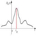
TDOA 기법을 기반으로 하는 위치추정 기법은 신호 도달지연시간의 차이를 이용한 위치추정 기법으로서, 그 위치추정 원리는 기준센서와 임의의 다른 센서(GPS 수신기)를 배치하고, 이들 두 센서에서 각각 수신된 신호간의 도달지연 시간의 차이를 이용하면 신호 발생원의 위치를 구할 수 있는데, 이때 도달지연시간 차이에 의한 신호 발생원의 위치는 도 1(a)에 도시된 바와 같이 각각 쌍곡선의 형태로 표시될 수 있고, 이러한 여러 개의 쌍곡선이 만나는 지점을 구함으로써 신호 발생원의 위치를 추정하는 원리이다.The position estimation technique based on the TDOA technique is a position estimation technique using a difference in signal arrival delay time. The position estimation principle is to locate a reference sensor and any other sensor (GPS receiver) and receive each of these two sensors. By using the difference in arrival delay time between signals, the position of the signal source can be obtained. In this case, the position of the signal source due to the difference in arrival delay time can be displayed in the form of a hyperbolic curve as shown in FIG. In other words, it is the principle of estimating the position of the signal source by finding the point where these hyperbolas meet.
이때 두 센서간의 도달지연시간 차이는 아래의 수학식 1로 표현되는 교차상관함수(Cross-Correlation Function)를 이용하여 구할 수 있으며, 두 센서에서 수신된 신호를 교차상관시키게 되면 교차상관값(

In this case, the difference in arrival delay between the two sensors can be obtained by using a cross-correlation function represented by Equation 1 below. When the signals received from the two sensors are correlated, the cross-correlation value (
[수학식 1] [Equation 1]

여기서,


here,
실제에 있어서는 위 수학식 1을 이용하여 TDOA 측정치를 구하는 과정은 이산시간영역에서 구현되므로 위 수학식 1을 이산시간 영역에서의 식으로 나타내면 아래의 수학식 2와 같이 표현된다.
In practice, since the process of obtaining the TDOA measurement value using Equation 1 above is implemented in the discrete time domain, Equation 1 is expressed as
[수학식 2] &Quot; (2) "

여기서


here
그러나 위 수학식 2를 이용하여 TDOA 측정치를 계산할 때 수신된 신호를 알지 못하는 상태에서 수신된 신호에 대해 교차상관을 행하게 되면 교차상관값(


However, when calculating the TDOA
본 발명은 상기와 같은 종래의 TDOA 기법에 의해 미지 신호 발생원의 위치를 측정하는 방법이 가지는 문제점을 해결하기 위해 안출된 것으로, TDOA 기법을 기반으로 하면서도 미지 신호를 발생시키는 발생원의 위치를 정확하게 측정할 수 있도록 하는 미지 신호 발생원 위치 측정방법을 제공하는 데에 그 목적이 있다.
The present invention has been made to solve the problem of the method of measuring the position of the unknown signal source by the conventional TDOA technique as described above, and to accurately measure the position of the source that generates the unknown signal based on the TDOA technique. It is an object of the present invention to provide a method for measuring an unknown signal source position.
상기와 같은 본 발명의 목적은 TDOA 기법을 기반으로 하는 미지 신호 발생원의 위치 측정방법을, 다수 개의 센서를 이용하여 미지 신호를 수신하여 획득하는 데이터 획득단계와; 상기 데이터 획득단계에 의해 획득된 신호에 대해 교차상관을 수행하여 교차상관값을 구한 다음, 상기 교차상관값을 이용하여 목적함수의 값을 계산하는 목적함수의 값 계산단계와; TDOA 측정치 산출을 위한 기준센서를 선정하는 기준센서 선정단계와; 상기 기준센서 선정단계에 의해 선정된 기준센서와
An object of the present invention as described above is a data acquisition step of receiving and obtaining an unknown signal using a plurality of sensors, the method for measuring the position of an unknown signal source based on the TDOA technique; Calculating a cross-correlation value by performing cross-correlation on the signal obtained by the data acquiring step, and then calculating a value of the target function using the cross-correlation value; A reference sensor selection step of selecting a reference sensor for calculating a TDOA measurement value; The reference sensor selected by the reference sensor selection step and
본 발명은 GPS 신호를 수신하는 다수 개의 센서 중 목적함수의 값을 최대로 하는 센서를 기준센서로 미리 선정한 다음, 이 선정된 기준센서를 이용하여 미지 신호 발생원의 위치를 측정하기 때문에 종래의 미지신호 발생원 위치 측정방법에 비해 샘플링 주기에 의한 영향이 줄어들어 미지 신호 발생원의 위치를 더욱 정확하게 찾을 수 있다.
According to the present invention, since a sensor that maximizes the value of an objective function among a plurality of sensors receiving a GPS signal is selected in advance as a reference sensor, the unknown signal source is measured using the selected reference sensor. Compared to the method of measuring the source position, the influence of the sampling period is reduced, so that the position of the unknown signal source can be more accurately located.
도 1a, 도 1b은 미지 신호 발생원의 위치추정 원리 개략도,
도 2는 본 발명에 따른 TDOA 기법을 기반으로 하는 미지신호 발생원의 위치 측정방법을 순서대로 나타낸 흐름도,
도 3은 본 발명에 따른 TDOA 기법을 기반으로 하는 미지신호 발생원의 위치 측정방법의 논리구조를 나타낸 흐름도,
도 4는 종래의 일반적인 TDOA 기법의 수평 위치 오차를 나타낸 그래프,
도 5는 본 발명에 따른 TDOA 기법의 수평 위치 오차를 나타낸 그래프이다.
1A and 1B are schematic diagrams illustrating a position estimation principle of an unknown signal source;
2 is a flowchart illustrating a method of measuring a position of an unknown signal source based on a TDOA technique according to the present invention;
3 is a flowchart illustrating a logic structure of a method for measuring a location of an unknown signal source based on a TDOA technique according to the present invention;
4 is a graph showing a horizontal position error of a conventional TDOA technique,
5 is a graph showing the horizontal position error of the TDOA technique according to the present invention.
이하에서는 바람직한 실시예를 도시한 첨부 도면을 통해 본 발명의 구성을 더욱 상세히 설명한다.
Hereinafter, the configuration of the present invention through the accompanying drawings showing a preferred embodiment will be described in more detail.
본 발명은 미지 신호 발생원의 위치를 정확하게 측정할 수 있도록 하는 TDOA 기법을 이용한 미지 신호 발생원 위치 측정방법을 제공하고자 하는 것으로, 이를 위해 본 발명은 도 2 및 도 3에 도시된 바와 같이 데이터 획득단계(S100), 목적함수의 값 계산단계(S200), 기준센서 선정단계(S300), TDOA 측정치 산출단계(S400) 및 위치 측정단계(S500)로 이루어진다.
The present invention is to provide a method for measuring the location of an unknown signal source using a TDOA technique that can accurately measure the location of the unknown signal source, for this purpose, the present invention is a data acquisition step (2) S100), the value calculation step (S200) of the objective function, the reference sensor selection step (S300), the TDOA measurement value calculation step (S400) and the position measurement step (S500).
(1) 데이터 획득단계(S100)(1) Data Acquisition Step (S100)
데이터 취득단계(S100)는 다수 개(N개)의 GPS 수신기(센서)를 이용하여 미지 신호를 수신하여 획득하는 단계이다.The data acquisition step S100 is a step of receiving and acquiring an unknown signal using a plurality (N) GPS receivers (sensors).
GPS 수신기는 항법위성 등으로부터 방사되는 GPS 신호를 수신하는데, 이러한 GPS 신호는 기지의 신호이다. 그런데 GPS 수신기(센서)에 의해 수신되는 신호에는 이러한 기지의 신호 즉, GPS 신호(위 수학식 1에서

The GPS receiver receives a GPS signal emitted from a navigation satellite or the like, which is a known signal. However, the signal received by the GPS receiver (sensor) includes such a known signal, that is, a GPS signal (Equation 1 above)
(2) 목적함수의 값 계산단계(S200)(2) Step of calculating the value of the objective function (S200)
목적함수의 값 계산단계(S200)는 위 데이터 취득단계(S100)에 의해 취득된 미지 신호를 이용하여 이들 신호에 대해 교차상관을 수행하여 교차상관값(

The value calculation step (S200) of the objective function performs cross-correlation on these signals by using the unknown signals obtained by the data acquisition step (S100) above, so that the cross-correlation value (
기지의 신호에 대해 수학식 2를 적용하여 교차상관을 수행하게 되면 교차상관값이 최대가 되도록 하는 TDOA 측정치를 계산해낼 수 있지만, 센서로부터 수신된 신호에 미지 신호가 포함되어 있는 경우에는 앞서 설명한 바와 같이 교차상관값(

If cross-correlation is performed by applying
따라서 본 발명에서는 아래의 수학식 3에 의해 목적함수(


Therefore, in the present invention, the following objective function (3)
[수학식 3] &Quot; (3) "

여기서,


here,
교차상관값은 N개의 센서 중 어느 센서를 기준센서로 선정하는지에 따라 다르게 나타나고, 따라서 본 발명에서는 기준센서를 차례대로 변경하여가면서 기준센서(


The cross-correlation value is different depending on which of the N sensors is selected as the reference sensor. Therefore, in the present invention, the reference sensor is sequentially changed while the reference sensor is changed.
(3) 기준센서 선정단계(S300)(3) Selection step of reference sensor (S300)
기준센서 선정단계(S300)는 상기 목적함수의 값 계산단계(S200)에서 계산된 목적함수의 값 중에서 목적함수의 값을 최대로 하는 기준센서를 TDOA 측정치 산출을 위한 기준센서로서 선정하는 단계이다.
Reference sensor selection step (S300) is a step of selecting a reference sensor for maximizing the value of the objective function among the values of the objective function calculated in the value calculation step (S200) of the objective function as a reference sensor for calculating the TDOA measurement value.
앞서 설명한 바와 같이 어느 센서를 기준센서로 정의하는지에 따라 측정 성능이 달라지기 때문에 본 발명에서는 상기의 수학식 3을 사용하여 기준센서를 차례로 바꾸어가면서 목적함수의 값을 계산한 다음, 목적함수의 값을 최대로 하는 기준센서를 TDOA 측정치 산출을 위한 기준센서로서 선정한다.As described above, since the measurement performance varies depending on which sensor is defined as the reference sensor, the present invention calculates the value of the objective function by sequentially changing the reference
상기의 목적함수의 값 계산단계(S200)에 의해 목적함수의 값을 계산하는 경우 이상적인 환경에서의 목적함수의 값은 "최소값"이 1되고, "최대값"으로는 무한대가 된다.
When the value of the objective function is calculated by the value calculation step S200 of the objective function, the value of the objective function in an ideal environment is “minimum value” 1, and “maximum value” is infinite.
(4) TDOA 측정치 산출단계(S400)(4) TDOA measurement value calculation step (S400)
TDOA 측정치 산출단계(S400)는 기준센서 선정단계(S300)에 의해 선정된 기준센서를 기준센서로 두고 TDOA 측정치, 즉 선정된 기준센서(


The TDOA measurement value calculating step S400 is based on the reference sensor selected by the reference sensor selecting step S300 as the reference sensor, that is, the TDOA measurement value, that is, the selected reference sensor (
(5) 위치 측정단계(S500)(5) Position measurement step (S500)
위치 측정단계(S500)는 상기 TDOA 측정치 산출단계(S400)에 의해 TDOA 측정치(

Position measurement step (S500) is the TDOA measurement value (S400) by the TDOA measurement value calculation step (S400)
기준센서(


Reference sensor
[수학식 4]&Quot; (4) "

여기서,


here,
TDOA 측정치를 알게 되면 위 수학식 4로부터 미지 신호 발생원의 측정치

Once we know the TDOA measurement, we can measure the unknown signal source from
[수학식 5][Equation 5]


여기서,
here,
만약, N개의 센서가 존재하는 경우 1번째 센서를 기준센서(


If there are N sensors, the first sensor is referred to as the reference sensor (
[수학식 6]&Quot; (6) "

여기서,


상기 수학식 6에서 위치변화량(
Position change amount in Equation 6
[수학식 7][Equation 7]

여기서,
here,
따라서 미지 신호 발생원의 추정 위치좌표


Therefore, estimated position coordinate of unknown signal source
[수학식 8][Equation 8]

위 수학식 8에서 알 수 있는 바와 같이 미지 신호 발생원의 추정 위치


As can be seen from Equation 8, the estimated position of the unknown signal source
본 발명자 등은 상기와 같은 구성으로 이루어진 본 발명의 TDOA 기법에 기반을 둔 미지 신호 발생원의 위치 측정방법의 유용성 등을 확인하기 위해 모의실험을 행하였으며, 이하에서는 이에 대해 설명한다.The inventors have performed a simulation to confirm the usefulness of the method for measuring the location of an unknown signal source based on the TDOA technique of the present invention having the above configuration, and will be described below.
모의실험은 MATLAB 기반에서 50회 Monte-Carlo 실험을 통해 이루어졌고, 송신전력은 5mW, 센서는 한 변이 4km인 정사각형의 모서리에 설치하였다.The simulation was carried out through 50 Monte-Carlo experiments based on MATLAB, and the transmission power was 5mW and the sensor was installed at the corner of square with 4km on one side.
도 4는 샘플링 주파수가 6MHz일 때 종래의 일반적인 TDOA 기법을 이용하여 구한 미지 신호 발생원의 위치에 있어서의 수평 위치오차를 나타낸 것으로, 이 그래프에 도시된 바와 같이 미지 신호 발생원이 센서간의 설치 거리(4km)보다 더 멀어지는 위치부터 오차가 급격하게 증가하였고, 방위각에 따라서도 편차가 크게 나타났는데, 거리에 따른 오차가 크게 나타나는 것은 DOP(Dilution of Precision)가 켜졌기 때문이고, 방위각에 따른 편차가 크게 나타난 것은 종래의 방식은 기준센서를 임의로 선정한데 따른 것으로 추측된다.Figure 4 shows the horizontal position error in the position of the unknown signal source obtained by using a conventional TDOA technique when the sampling frequency is 6MHz, as shown in this graph the installation distance between the sensor (4km From the distance farther away from), the error increased sharply, and the deviation was large depending on the azimuth angle. It is assumed that the conventional method is based on arbitrarily selecting a reference sensor.
도 5는 본 발명에 따른 미지 신호 발생원 위치 측정방법을 적용하여 구한 미지 신호 발생원에 대한 위치에 있어서의 수평위치 오차를 나타낸 그래프로서, 도 3의 그래프와 비교해 보면 본 발명에 따른 미지 신호 발생원 위치 측정방법이 종래의 방법에 비해 미지 신호 발생원의 위치를 더욱 정확하게 측정하고 있음을 알 수 있다.
FIG. 5 is a graph showing a horizontal position error in a position with respect to an unknown signal source obtained by applying an unknown signal source position measuring method according to the present invention. Compared with the graph of FIG. It can be seen that the method measures the position of the unknown signal source more accurately than the conventional method.
이상 설명한 바와 같이 본 발명은 GPS 신호를 수신하는 다수 개의 센서 중 목적함수의 값을 최대로 하는 센서를 기준센서를 미리 선정한 다음, 이 선정된 기준센서를 이용하여 미지 신호 발생원의 위치를 측정하기 때문에 종래의 미지신호 발생원 위치 측정방법에 비해 미지 신호 발생원의 위치를 더욱 정확하게 찾을 수 있다.
As described above, the present invention selects a sensor that maximizes the value of the objective function among the plurality of sensors that receive the GPS signal in advance, and then measures the position of the unknown signal source using the selected reference sensor. Compared to the conventional unknown signal source measurement method, the location of the unknown signal source can be found more accurately.
Claims (3)
Translated fromKorean다수 개의 센서를 이용하여 미지 신호를 수신하여 획득하는 데이터 획득단계(S100)와;
상기 데이터 획득단계(S100)에 의해 획득된 신호에 대해 이산 지연시간(


TDOA 측정치 산출을 위한 기준센서를 선정하는 기준센서 선정단계(S300)와;
상기 기준센서 선정단계(S300)에 의해 선정된 기준센서(


상기 TDOA 측정치 산출단계(S400)에 의해 산출된 TDOA 측정치(

In the method for measuring the position of an unknown signal source based on the TDOA technique,
A data acquisition step of receiving and acquiring an unknown signal using a plurality of sensors (S100);
Discrete delay time for the signal obtained by the data acquisition step (S100)
A reference sensor selecting step (S300) of selecting a reference sensor for calculating a TDOA measurement value;
Reference sensor selected by the reference sensor selection step (S300) (
The TDOA measurement value calculated by the TDOA measurement value calculating step (S400)
상기 목적함수의 값 계산단계(S200)에서의 목적함수의 값은 아래의 수학식 3에 의해 계산되는 것을 특징으로 하는 TDOA 기법을 기반으로 하는 미지 신호 발생원 위치 추정방법.
[수학식 3]

여기서,


The method according to claim 1,
The unknown signal source position estimation method based on the TDOA technique, characterized in that the value of the objective function in the calculation of the objective function (S200) is calculated by Equation 3 below.
&Quot; (3) "
here,
상기 기준센서 선정단계(S300)에서 선정되는 기준센서는 상기 목적함수의 값 계산단계(S200)에서 계산된 목적함수의 값 중에서 목적함수의 값을 최대로 하는 기준센서인 것을 특징으로 하는 TDOA 기법을 기반으로 하는 미지 신호 발생원 위치 추정방법.The method according to claim 2,
The reference sensor selected in the reference sensor selection step (S300) is a reference sensor for maximizing the value of the objective function among the values of the objective function calculated in the value calculation step (S200) of the target function. Based signal source estimation method based on.
Priority Applications (2)
| Application Number | Priority Date | Filing Date | Title |
|---|---|---|---|
| KR1020120097273AKR101224512B1 (en) | 2012-09-03 | 2012-09-03 | Positioning method of unknown signal generator based on tdoa method |
| US13/857,958US20140062791A1 (en) | 2012-09-03 | 2013-04-05 | Localization method of source of unknown signal based on tdoa method |
Applications Claiming Priority (1)
| Application Number | Priority Date | Filing Date | Title |
|---|---|---|---|
| KR1020120097273AKR101224512B1 (en) | 2012-09-03 | 2012-09-03 | Positioning method of unknown signal generator based on tdoa method |
Publications (1)
| Publication Number | Publication Date |
|---|---|
| KR101224512B1true KR101224512B1 (en) | 2013-01-21 |
Family
ID=47842308
Family Applications (1)
| Application Number | Title | Priority Date | Filing Date |
|---|---|---|---|
| KR1020120097273AExpired - Fee RelatedKR101224512B1 (en) | 2012-09-03 | 2012-09-03 | Positioning method of unknown signal generator based on tdoa method |
Country Status (2)
| Country | Link |
|---|---|
| US (1) | US20140062791A1 (en) |
| KR (1) | KR101224512B1 (en) |
Cited By (10)
| Publication number | Priority date | Publication date | Assignee | Title |
|---|---|---|---|---|
| KR101515513B1 (en)* | 2014-07-29 | 2015-04-28 | 엘아이지넥스원 주식회사 | apparatus for estimating location based on time difference of arrival |
| KR101515512B1 (en)* | 2014-07-29 | 2015-04-28 | 엘아이지넥스원 주식회사 | Method for estimating location based on time difference of arrival |
| KR101532324B1 (en)* | 2014-03-13 | 2015-06-30 | 국방과학연구소 | Apparatus and Method of testing the performance of TDOA system |
| KR101854721B1 (en) | 2016-01-28 | 2018-05-04 | 김종길 | Time difference of arrival coordinate seraching apparatus and method using high speed binary search technique |
| CN110261819A (en)* | 2019-06-19 | 2019-09-20 | 南京航空航天大学 | Multiple no-manned plane co-located method based on delay compensation |
| CN110824424A (en)* | 2019-11-19 | 2020-02-21 | 金陵科技学院 | Acoustic emission source positioning method based on wavelet transformation |
| CN111505575A (en)* | 2020-03-23 | 2020-08-07 | 宁波大学 | Sensor selection method aiming at TDOA (time difference of arrival) location based on conversion TOA (time of arrival) model |
| CN111505576A (en)* | 2020-03-23 | 2020-08-07 | 宁波大学 | Sensor selection method aiming at TDOA (time difference of arrival) location |
| CN113702901A (en)* | 2021-09-02 | 2021-11-26 | 南京航空航天大学 | Cross-correlation delay estimation method based on signal correlation enhancement |
| KR102572546B1 (en)* | 2022-11-15 | 2023-08-29 | 윤영민 | Device and method of detecting multiple signal differences in single frequency receiver |
Families Citing this family (8)
| Publication number | Priority date | Publication date | Assignee | Title |
|---|---|---|---|---|
| US8401560B2 (en) | 2009-03-31 | 2013-03-19 | Empire Technology Development Llc | Infrastructure for location discovery |
| CN110808934A (en)* | 2019-11-01 | 2020-02-18 | 中国电子科技集团公司第二十九研究所 | Time difference estimation method and device for chirp signal |
| US11353541B2 (en) | 2020-06-03 | 2022-06-07 | Zhejiang University | Localizing a target device based on measurements from a measurement device array |
| CN112034425B (en)* | 2020-09-15 | 2023-03-21 | 中南大学 | Acoustic emission source linearity correction positioning method and system with unknown wave velocity and storage medium |
| CN112799116A (en)* | 2020-12-22 | 2021-05-14 | 武汉第二船舶设计研究所(中国船舶重工集团公司第七一九研究所) | Method for increasing source searching distance based on cross-correlation technology |
| CN112954591B (en)* | 2021-02-10 | 2022-04-15 | 北京理工大学 | Cooperative distributed positioning method and system |
| CN114442034B (en)* | 2022-02-10 | 2024-10-22 | 广东行远机器人技术有限公司 | Positioning method and device based on hyperbola TDOA and computer readable storage medium |
| CN118151238B (en)* | 2024-02-28 | 2025-03-21 | 中国科学院地质与地球物理研究所 | A seismic wave positioning method, system, computer equipment and storage medium |
Citations (4)
| Publication number | Priority date | Publication date | Assignee | Title |
|---|---|---|---|---|
| KR19990063678A (en)* | 1995-09-20 | 1999-07-26 | 더 세크리터리 오브 스테이트 포 디펜스 | Source placement of unknown signal |
| KR20080050944A (en)* | 2006-12-04 | 2008-06-10 | 한국전자통신연구원 | Position determination device and method |
| KR20090110839A (en)* | 2006-12-27 | 2009-10-22 | 트루포지션, 인크. | Mobile, Repeated Geolocation of RF Radiators |
| KR20100071353A (en)* | 2008-12-19 | 2010-06-29 | 재단법인 포항산업과학연구원 | Method for distance measurement of porous media and measuring device thereof |
Family Cites Families (6)
| Publication number | Priority date | Publication date | Assignee | Title |
|---|---|---|---|---|
| US5008679A (en)* | 1990-01-31 | 1991-04-16 | Interferometrics Incorporated | Method and system for locating an unknown transmitter |
| GB9919525D0 (en)* | 1999-08-19 | 1999-10-20 | Secr Defence | Method and apparatus for locating the source of an unknown signal |
| US7403157B2 (en)* | 2006-09-13 | 2008-07-22 | Mitsubishi Electric Research Laboratories, Inc. | Radio ranging using sequential time-difference-of-arrival estimation |
| GB2443226B (en)* | 2006-10-28 | 2011-08-17 | Qinetiq Ltd | Method and apparatus for locating the source of an unknown signal |
| US8878725B2 (en)* | 2011-05-19 | 2014-11-04 | Exelis Inc. | System and method for geolocation of multiple unknown radio frequency signal sources |
| KR101221978B1 (en)* | 2012-09-03 | 2013-01-15 | 한국항공우주연구원 | Localization method of multiple jammers based on tdoa method |
- 2012
- 2012-09-03KRKR1020120097273Apatent/KR101224512B1/ennot_activeExpired - Fee Related
- 2013
- 2013-04-05USUS13/857,958patent/US20140062791A1/ennot_activeAbandoned
Patent Citations (4)
| Publication number | Priority date | Publication date | Assignee | Title |
|---|---|---|---|---|
| KR19990063678A (en)* | 1995-09-20 | 1999-07-26 | 더 세크리터리 오브 스테이트 포 디펜스 | Source placement of unknown signal |
| KR20080050944A (en)* | 2006-12-04 | 2008-06-10 | 한국전자통신연구원 | Position determination device and method |
| KR20090110839A (en)* | 2006-12-27 | 2009-10-22 | 트루포지션, 인크. | Mobile, Repeated Geolocation of RF Radiators |
| KR20100071353A (en)* | 2008-12-19 | 2010-06-29 | 재단법인 포항산업과학연구원 | Method for distance measurement of porous media and measuring device thereof |
Cited By (14)
| Publication number | Priority date | Publication date | Assignee | Title |
|---|---|---|---|---|
| KR101532324B1 (en)* | 2014-03-13 | 2015-06-30 | 국방과학연구소 | Apparatus and Method of testing the performance of TDOA system |
| KR101515513B1 (en)* | 2014-07-29 | 2015-04-28 | 엘아이지넥스원 주식회사 | apparatus for estimating location based on time difference of arrival |
| KR101515512B1 (en)* | 2014-07-29 | 2015-04-28 | 엘아이지넥스원 주식회사 | Method for estimating location based on time difference of arrival |
| KR101854721B1 (en) | 2016-01-28 | 2018-05-04 | 김종길 | Time difference of arrival coordinate seraching apparatus and method using high speed binary search technique |
| CN110261819A (en)* | 2019-06-19 | 2019-09-20 | 南京航空航天大学 | Multiple no-manned plane co-located method based on delay compensation |
| CN110824424A (en)* | 2019-11-19 | 2020-02-21 | 金陵科技学院 | Acoustic emission source positioning method based on wavelet transformation |
| CN111505575A (en)* | 2020-03-23 | 2020-08-07 | 宁波大学 | Sensor selection method aiming at TDOA (time difference of arrival) location based on conversion TOA (time of arrival) model |
| CN111505576A (en)* | 2020-03-23 | 2020-08-07 | 宁波大学 | Sensor selection method aiming at TDOA (time difference of arrival) location |
| CN111505576B (en)* | 2020-03-23 | 2022-01-18 | 宁波大学 | Sensor selection method aiming at TDOA (time difference of arrival) location |
| CN111505575B (en)* | 2020-03-23 | 2022-02-11 | 宁波大学 | Sensor selection method aiming at TDOA (time difference of arrival) location based on conversion TOA (time of arrival) model |
| CN113702901A (en)* | 2021-09-02 | 2021-11-26 | 南京航空航天大学 | Cross-correlation delay estimation method based on signal correlation enhancement |
| CN113702901B (en)* | 2021-09-02 | 2024-06-11 | 南京航空航天大学 | Cross-correlation time delay estimation method based on signal correlation enhancement |
| KR102572546B1 (en)* | 2022-11-15 | 2023-08-29 | 윤영민 | Device and method of detecting multiple signal differences in single frequency receiver |
| WO2024106899A1 (en)* | 2022-11-15 | 2024-05-23 | 윤영민 | Device and method for detecting difference in signals generated from multiple channels in single frequency receiver |
Also Published As
| Publication number | Publication date |
|---|---|
| US20140062791A1 (en) | 2014-03-06 |
Similar Documents
| Publication | Publication Date | Title |
|---|---|---|
| KR101224512B1 (en) | Positioning method of unknown signal generator based on tdoa method | |
| KR101221978B1 (en) | Localization method of multiple jammers based on tdoa method | |
| CN110945382B (en) | Method for providing and improving position probability distribution for GNSS received data | |
| US11555699B2 (en) | Systems and methods for determining when an estimated altitude of a mobile device can be used for calibration or location determination | |
| US8909258B2 (en) | Context and map aiding for self-learning | |
| US11073441B2 (en) | Systems and methods for determining when to calibrate a pressure sensor of a mobile device | |
| JP5450081B2 (en) | Method, software and system for determining the position of a user device | |
| US10349214B2 (en) | Localization using access point | |
| EP2160624A1 (en) | Geofencing and route adherence in global positioning system with signals from fewer than three satellites | |
| Norouzi et al. | Joint time difference of arrival/angle of arrival position finding in passive radar | |
| KR20150132165A (en) | Techniques to Improve the Performance of a Fixed, Timing-Based Radio Positioning Network Using External Assistance Information | |
| Lategahn et al. | Tdoa and rss based extended kalman filter for indoor person localization | |
| US20240159529A1 (en) | Systems and methods for extending the spatial coverage of a reference pressure network | |
| WO2016064631A1 (en) | Mitigating effects of multipath during position computation | |
| KR20130036145A (en) | A moving information determination apparatus, a receiver, and a method thereby | |
| RU2683584C1 (en) | Method for remote monitoring of positioning of the vehicles | |
| US20250052571A1 (en) | Systems And Methods For Extending The Spatial Coverage Of A Reference Pressure Network | |
| JP5341459B2 (en) | Positioning device | |
| Kirkko-Jaakkola et al. | Improving TTFF by two-satellite GNSS positioning | |
| CN117434565A (en) | A fusion positioning method and device based on multiple receiving antennas | |
| CN108267713B (en) | Improved TDOA emission source positioning algorithm | |
| US9883342B2 (en) | Localization using access point | |
| Wei et al. | Performance analysis of TDOA based localization using SDRs | |
| KR102677918B1 (en) | Single-epoch pseudo-range localization under variable ionospheric delay. | |
| KR20080048710A (en) | Time measuring device and method |
Legal Events
| Date | Code | Title | Description |
|---|---|---|---|
| A201 | Request for examination | ||
| PA0109 | Patent application | St.27 status event code:A-0-1-A10-A12-nap-PA0109 | |
| PA0201 | Request for examination | St.27 status event code:A-1-2-D10-D11-exm-PA0201 | |
| A302 | Request for accelerated examination | ||
| PA0302 | Request for accelerated examination | St.27 status event code:A-1-2-D10-D16-exm-PA0302 St.27 status event code:A-1-2-D10-D17-exm-PA0302 | |
| E902 | Notification of reason for refusal | ||
| PE0902 | Notice of grounds for rejection | St.27 status event code:A-1-2-D10-D21-exm-PE0902 | |
| P11-X000 | Amendment of application requested | St.27 status event code:A-2-2-P10-P11-nap-X000 | |
| P13-X000 | Application amended | St.27 status event code:A-2-2-P10-P13-nap-X000 | |
| E701 | Decision to grant or registration of patent right | ||
| PE0701 | Decision of registration | St.27 status event code:A-1-2-D10-D22-exm-PE0701 | |
| GRNT | Written decision to grant | ||
| PR0701 | Registration of establishment | St.27 status event code:A-2-4-F10-F11-exm-PR0701 | |
| PR1002 | Payment of registration fee | Fee payment year number:1 St.27 status event code:A-2-2-U10-U11-oth-PR1002 | |
| PG1601 | Publication of registration | St.27 status event code:A-4-4-Q10-Q13-nap-PG1601 | |
| P14-X000 | Amendment of ip right document requested | St.27 status event code:A-5-5-P10-P14-nap-X000 | |
| P16-X000 | Ip right document amended | St.27 status event code:A-5-5-P10-P16-nap-X000 | |
| Q16-X000 | A copy of ip right certificate issued | St.27 status event code:A-4-4-Q10-Q16-nap-X000 | |
| P14-X000 | Amendment of ip right document requested | St.27 status event code:A-5-5-P10-P14-nap-X000 | |
| R15-X000 | Change to inventor requested | St.27 status event code:A-5-5-R10-R15-oth-X000 | |
| P16-X000 | Ip right document amended | St.27 status event code:A-5-5-P10-P16-nap-X000 | |
| Q16-X000 | A copy of ip right certificate issued | St.27 status event code:A-4-4-Q10-Q16-nap-X000 | |
| R16-X000 | Change to inventor recorded | St.27 status event code:A-5-5-R10-R16-oth-X000 | |
| G170 | Re-publication after modification of scope of protection [patent] | ||
| PG1701 | Publication of correction | Patent document republication publication date:20131218 Republication note text:Request for Correction Notice (Document Request) Gazette number:1012245120000 Gazette reference publication date:20130121 St.27 status event code:A-5-5-P10-P19-oth-PG1701 | |
| PR1001 | Payment of annual fee | Fee payment year number:4 St.27 status event code:A-4-4-U10-U11-oth-PR1001 | |
| FPAY | Annual fee payment | Payment date:20161121 Year of fee payment:5 | |
| PR1001 | Payment of annual fee | Fee payment year number:5 St.27 status event code:A-4-4-U10-U11-oth-PR1001 | |
| LAPS | Lapse due to unpaid annual fee | ||
| PC1903 | Unpaid annual fee | Not in force date:20180116 Payment event data comment text:Termination Category : DEFAULT_OF_REGISTRATION_FEE St.27 status event code:A-4-4-U10-U13-oth-PC1903 | |
| PC1903 | Unpaid annual fee | Ip right cessation event data comment text:Termination Category : DEFAULT_OF_REGISTRATION_FEE Not in force date:20180116 St.27 status event code:N-4-6-H10-H13-oth-PC1903 | |
| PN2301 | Change of applicant | St.27 status event code:A-5-5-R10-R11-asn-PN2301 St.27 status event code:A-5-5-R10-R13-asn-PN2301 | |
| PN2301 | Change of applicant | St.27 status event code:A-5-5-R10-R11-asn-PN2301 St.27 status event code:A-5-5-R10-R13-asn-PN2301 |