KR101222955B1 - Liquid Crystal Display Device And Method For Fabricating The Same - Google Patents
Liquid Crystal Display Device And Method For Fabricating The SameDownload PDFInfo
- Publication number
- KR101222955B1 KR101222955B1KR1020050131564AKR20050131564AKR101222955B1KR 101222955 B1KR101222955 B1KR 101222955B1KR 1020050131564 AKR1020050131564 AKR 1020050131564AKR 20050131564 AKR20050131564 AKR 20050131564AKR 101222955 B1KR101222955 B1KR 101222955B1
- Authority
- KR
- South Korea
- Prior art keywords
- common electrode
- viewing angle
- liquid crystal
- substrate
- subpixels
- Prior art date
- Legal status (The legal status is an assumption and is not a legal conclusion. Google has not performed a legal analysis and makes no representation as to the accuracy of the status listed.)
- Expired - Fee Related
Links
Images


Classifications
- G—PHYSICS
- G02—OPTICS
- G02F—OPTICAL DEVICES OR ARRANGEMENTS FOR THE CONTROL OF LIGHT BY MODIFICATION OF THE OPTICAL PROPERTIES OF THE MEDIA OF THE ELEMENTS INVOLVED THEREIN; NON-LINEAR OPTICS; FREQUENCY-CHANGING OF LIGHT; OPTICAL LOGIC ELEMENTS; OPTICAL ANALOGUE/DIGITAL CONVERTERS
- G02F1/00—Devices or arrangements for the control of the intensity, colour, phase, polarisation or direction of light arriving from an independent light source, e.g. switching, gating or modulating; Non-linear optics
- G02F1/01—Devices or arrangements for the control of the intensity, colour, phase, polarisation or direction of light arriving from an independent light source, e.g. switching, gating or modulating; Non-linear optics for the control of the intensity, phase, polarisation or colour
- G02F1/13—Devices or arrangements for the control of the intensity, colour, phase, polarisation or direction of light arriving from an independent light source, e.g. switching, gating or modulating; Non-linear optics for the control of the intensity, phase, polarisation or colour based on liquid crystals, e.g. single liquid crystal display cells
- G02F1/133—Constructional arrangements; Operation of liquid crystal cells; Circuit arrangements
- G02F1/136—Liquid crystal cells structurally associated with a semi-conducting layer or substrate, e.g. cells forming part of an integrated circuit
- G02F1/1362—Active matrix addressed cells
- G—PHYSICS
- G02—OPTICS
- G02F—OPTICAL DEVICES OR ARRANGEMENTS FOR THE CONTROL OF LIGHT BY MODIFICATION OF THE OPTICAL PROPERTIES OF THE MEDIA OF THE ELEMENTS INVOLVED THEREIN; NON-LINEAR OPTICS; FREQUENCY-CHANGING OF LIGHT; OPTICAL LOGIC ELEMENTS; OPTICAL ANALOGUE/DIGITAL CONVERTERS
- G02F1/00—Devices or arrangements for the control of the intensity, colour, phase, polarisation or direction of light arriving from an independent light source, e.g. switching, gating or modulating; Non-linear optics
- G02F1/01—Devices or arrangements for the control of the intensity, colour, phase, polarisation or direction of light arriving from an independent light source, e.g. switching, gating or modulating; Non-linear optics for the control of the intensity, phase, polarisation or colour
- G02F1/13—Devices or arrangements for the control of the intensity, colour, phase, polarisation or direction of light arriving from an independent light source, e.g. switching, gating or modulating; Non-linear optics for the control of the intensity, phase, polarisation or colour based on liquid crystals, e.g. single liquid crystal display cells
- G02F1/133—Constructional arrangements; Operation of liquid crystal cells; Circuit arrangements
- G02F1/1333—Constructional arrangements; Manufacturing methods
- G02F1/1343—Electrodes
- G—PHYSICS
- G02—OPTICS
- G02F—OPTICAL DEVICES OR ARRANGEMENTS FOR THE CONTROL OF LIGHT BY MODIFICATION OF THE OPTICAL PROPERTIES OF THE MEDIA OF THE ELEMENTS INVOLVED THEREIN; NON-LINEAR OPTICS; FREQUENCY-CHANGING OF LIGHT; OPTICAL LOGIC ELEMENTS; OPTICAL ANALOGUE/DIGITAL CONVERTERS
- G02F1/00—Devices or arrangements for the control of the intensity, colour, phase, polarisation or direction of light arriving from an independent light source, e.g. switching, gating or modulating; Non-linear optics
- G02F1/01—Devices or arrangements for the control of the intensity, colour, phase, polarisation or direction of light arriving from an independent light source, e.g. switching, gating or modulating; Non-linear optics for the control of the intensity, phase, polarisation or colour
- G02F1/13—Devices or arrangements for the control of the intensity, colour, phase, polarisation or direction of light arriving from an independent light source, e.g. switching, gating or modulating; Non-linear optics for the control of the intensity, phase, polarisation or colour based on liquid crystals, e.g. single liquid crystal display cells
- G02F1/1323—Arrangements for providing a switchable viewing angle
- G—PHYSICS
- G02—OPTICS
- G02F—OPTICAL DEVICES OR ARRANGEMENTS FOR THE CONTROL OF LIGHT BY MODIFICATION OF THE OPTICAL PROPERTIES OF THE MEDIA OF THE ELEMENTS INVOLVED THEREIN; NON-LINEAR OPTICS; FREQUENCY-CHANGING OF LIGHT; OPTICAL LOGIC ELEMENTS; OPTICAL ANALOGUE/DIGITAL CONVERTERS
- G02F1/00—Devices or arrangements for the control of the intensity, colour, phase, polarisation or direction of light arriving from an independent light source, e.g. switching, gating or modulating; Non-linear optics
- G02F1/01—Devices or arrangements for the control of the intensity, colour, phase, polarisation or direction of light arriving from an independent light source, e.g. switching, gating or modulating; Non-linear optics for the control of the intensity, phase, polarisation or colour
- G02F1/13—Devices or arrangements for the control of the intensity, colour, phase, polarisation or direction of light arriving from an independent light source, e.g. switching, gating or modulating; Non-linear optics for the control of the intensity, phase, polarisation or colour based on liquid crystals, e.g. single liquid crystal display cells
- G02F1/133—Constructional arrangements; Operation of liquid crystal cells; Circuit arrangements
- G02F1/1333—Constructional arrangements; Manufacturing methods
- G02F1/1335—Structural association of cells with optical devices, e.g. polarisers or reflectors
- G02F1/133509—Filters, e.g. light shielding masks
- G02F1/133514—Colour filters
- G—PHYSICS
- G02—OPTICS
- G02F—OPTICAL DEVICES OR ARRANGEMENTS FOR THE CONTROL OF LIGHT BY MODIFICATION OF THE OPTICAL PROPERTIES OF THE MEDIA OF THE ELEMENTS INVOLVED THEREIN; NON-LINEAR OPTICS; FREQUENCY-CHANGING OF LIGHT; OPTICAL LOGIC ELEMENTS; OPTICAL ANALOGUE/DIGITAL CONVERTERS
- G02F1/00—Devices or arrangements for the control of the intensity, colour, phase, polarisation or direction of light arriving from an independent light source, e.g. switching, gating or modulating; Non-linear optics
- G02F1/01—Devices or arrangements for the control of the intensity, colour, phase, polarisation or direction of light arriving from an independent light source, e.g. switching, gating or modulating; Non-linear optics for the control of the intensity, phase, polarisation or colour
- G02F1/13—Devices or arrangements for the control of the intensity, colour, phase, polarisation or direction of light arriving from an independent light source, e.g. switching, gating or modulating; Non-linear optics for the control of the intensity, phase, polarisation or colour based on liquid crystals, e.g. single liquid crystal display cells
- G02F1/133—Constructional arrangements; Operation of liquid crystal cells; Circuit arrangements
- G02F1/1333—Constructional arrangements; Manufacturing methods
- G02F1/1343—Electrodes
- G02F1/134309—Electrodes characterised by their geometrical arrangement
- G02F1/134363—Electrodes characterised by their geometrical arrangement for applying an electric field parallel to the substrate, i.e. in-plane switching [IPS]
- G—PHYSICS
- G09—EDUCATION; CRYPTOGRAPHY; DISPLAY; ADVERTISING; SEALS
- G09G—ARRANGEMENTS OR CIRCUITS FOR CONTROL OF INDICATING DEVICES USING STATIC MEANS TO PRESENT VARIABLE INFORMATION
- G09G3/00—Control arrangements or circuits, of interest only in connection with visual indicators other than cathode-ray tubes
- G09G3/20—Control arrangements or circuits, of interest only in connection with visual indicators other than cathode-ray tubes for presentation of an assembly of a number of characters, e.g. a page, by composing the assembly by combination of individual elements arranged in a matrix no fixed position being assigned to or needed to be assigned to the individual characters or partial characters
- G09G3/34—Control arrangements or circuits, of interest only in connection with visual indicators other than cathode-ray tubes for presentation of an assembly of a number of characters, e.g. a page, by composing the assembly by combination of individual elements arranged in a matrix no fixed position being assigned to or needed to be assigned to the individual characters or partial characters by control of light from an independent source
- G09G3/36—Control arrangements or circuits, of interest only in connection with visual indicators other than cathode-ray tubes for presentation of an assembly of a number of characters, e.g. a page, by composing the assembly by combination of individual elements arranged in a matrix no fixed position being assigned to or needed to be assigned to the individual characters or partial characters by control of light from an independent source using liquid crystals
- G09G3/3607—Control arrangements or circuits, of interest only in connection with visual indicators other than cathode-ray tubes for presentation of an assembly of a number of characters, e.g. a page, by composing the assembly by combination of individual elements arranged in a matrix no fixed position being assigned to or needed to be assigned to the individual characters or partial characters by control of light from an independent source using liquid crystals for displaying colours or for displaying grey scales with a specific pixel layout, e.g. using sub-pixels
- G—PHYSICS
- G09—EDUCATION; CRYPTOGRAPHY; DISPLAY; ADVERTISING; SEALS
- G09G—ARRANGEMENTS OR CIRCUITS FOR CONTROL OF INDICATING DEVICES USING STATIC MEANS TO PRESENT VARIABLE INFORMATION
- G09G3/00—Control arrangements or circuits, of interest only in connection with visual indicators other than cathode-ray tubes
- G09G3/20—Control arrangements or circuits, of interest only in connection with visual indicators other than cathode-ray tubes for presentation of an assembly of a number of characters, e.g. a page, by composing the assembly by combination of individual elements arranged in a matrix no fixed position being assigned to or needed to be assigned to the individual characters or partial characters
- G09G3/34—Control arrangements or circuits, of interest only in connection with visual indicators other than cathode-ray tubes for presentation of an assembly of a number of characters, e.g. a page, by composing the assembly by combination of individual elements arranged in a matrix no fixed position being assigned to or needed to be assigned to the individual characters or partial characters by control of light from an independent source
- G09G3/36—Control arrangements or circuits, of interest only in connection with visual indicators other than cathode-ray tubes for presentation of an assembly of a number of characters, e.g. a page, by composing the assembly by combination of individual elements arranged in a matrix no fixed position being assigned to or needed to be assigned to the individual characters or partial characters by control of light from an independent source using liquid crystals
- G09G3/3611—Control of matrices with row and column drivers
- G09G3/3648—Control of matrices with row and column drivers using an active matrix
- G—PHYSICS
- G02—OPTICS
- G02F—OPTICAL DEVICES OR ARRANGEMENTS FOR THE CONTROL OF LIGHT BY MODIFICATION OF THE OPTICAL PROPERTIES OF THE MEDIA OF THE ELEMENTS INVOLVED THEREIN; NON-LINEAR OPTICS; FREQUENCY-CHANGING OF LIGHT; OPTICAL LOGIC ELEMENTS; OPTICAL ANALOGUE/DIGITAL CONVERTERS
- G02F1/00—Devices or arrangements for the control of the intensity, colour, phase, polarisation or direction of light arriving from an independent light source, e.g. switching, gating or modulating; Non-linear optics
- G02F1/01—Devices or arrangements for the control of the intensity, colour, phase, polarisation or direction of light arriving from an independent light source, e.g. switching, gating or modulating; Non-linear optics for the control of the intensity, phase, polarisation or colour
- G02F1/13—Devices or arrangements for the control of the intensity, colour, phase, polarisation or direction of light arriving from an independent light source, e.g. switching, gating or modulating; Non-linear optics for the control of the intensity, phase, polarisation or colour based on liquid crystals, e.g. single liquid crystal display cells
- G02F1/133—Constructional arrangements; Operation of liquid crystal cells; Circuit arrangements
- G02F1/1333—Constructional arrangements; Manufacturing methods
- G02F1/1343—Electrodes
- G02F1/134309—Electrodes characterised by their geometrical arrangement
- G02F1/134381—Hybrid switching mode, i.e. for applying an electric field with components parallel and orthogonal to the substrates
- G—PHYSICS
- G02—OPTICS
- G02F—OPTICAL DEVICES OR ARRANGEMENTS FOR THE CONTROL OF LIGHT BY MODIFICATION OF THE OPTICAL PROPERTIES OF THE MEDIA OF THE ELEMENTS INVOLVED THEREIN; NON-LINEAR OPTICS; FREQUENCY-CHANGING OF LIGHT; OPTICAL LOGIC ELEMENTS; OPTICAL ANALOGUE/DIGITAL CONVERTERS
- G02F2201/00—Constructional arrangements not provided for in groups G02F1/00 - G02F7/00
- G02F2201/52—RGB geometrical arrangements
- G—PHYSICS
- G09—EDUCATION; CRYPTOGRAPHY; DISPLAY; ADVERTISING; SEALS
- G09G—ARRANGEMENTS OR CIRCUITS FOR CONTROL OF INDICATING DEVICES USING STATIC MEANS TO PRESENT VARIABLE INFORMATION
- G09G2300/00—Aspects of the constitution of display devices
- G09G2300/04—Structural and physical details of display devices
- G09G2300/0439—Pixel structures
- G09G2300/0452—Details of colour pixel setup, e.g. pixel composed of a red, a blue and two green components
- G—PHYSICS
- G09—EDUCATION; CRYPTOGRAPHY; DISPLAY; ADVERTISING; SEALS
- G09G—ARRANGEMENTS OR CIRCUITS FOR CONTROL OF INDICATING DEVICES USING STATIC MEANS TO PRESENT VARIABLE INFORMATION
- G09G2320/00—Control of display operating conditions
- G09G2320/02—Improving the quality of display appearance
- G09G2320/028—Improving the quality of display appearance by changing the viewing angle properties, e.g. widening the viewing angle, adapting the viewing angle to the view direction
Landscapes
- Physics & Mathematics (AREA)
- Nonlinear Science (AREA)
- General Physics & Mathematics (AREA)
- Chemical & Material Sciences (AREA)
- Crystallography & Structural Chemistry (AREA)
- Optics & Photonics (AREA)
- Engineering & Computer Science (AREA)
- Mathematical Physics (AREA)
- Computer Hardware Design (AREA)
- Theoretical Computer Science (AREA)
- Geometry (AREA)
- Microelectronics & Electronic Packaging (AREA)
- Liquid Crystal (AREA)
Abstract
Translated fromKoreanDescription
Translated fromKorean도 1은 종래 기술에 의한 FFS 모드 액정표시소자의 평면도.1 is a plan view of a conventional FFS mode liquid crystal display device.
도 2는 도 1의 Ⅰ-Ⅰ'선상에서의 절단면도.FIG. 2 is a cross-sectional view taken along line II ′ of FIG. 1. FIG.
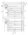
도 3은 본 발명에 의한 FFS 모드 액정표시소자의 평면도.3 is a plan view of the FFS mode liquid crystal display device according to the present invention.
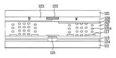
도 4는 도 3의 Ⅱ-Ⅱ'선상에서의 절단면도.4 is a cross-sectional view taken along line II-II ′ of FIG. 3.
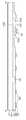
도 5는 본 발명에 의한 컬러필터층 어레이 기판의 패턴 배치도.5 is a pattern layout view of a color filter layer array substrate according to the present invention;
도 6a 및 도 6b는 본 발명에 의한 액정표시소자의 광시야각 모드를 설명하기 위한 단면도.6A and 6B are cross-sectional views illustrating a wide viewing angle mode of a liquid crystal display device according to the present invention.
도 7a 및 도 7b는 본 발명에 의한 액정표시소자의 협시야각 모드를 설명하기 위한 단면도.7A and 7B are cross-sectional views illustrating a narrow viewing angle mode of a liquid crystal display device according to the present invention.
도 8a 내지 8d는 도 3의 Ⅲ-Ⅲ'절단선에서의 공정단면도.8A to 8D are cross-sectional views of the process taken along line III-III ′ of FIG. 3.
*도면의 주요 부분에 대한 부호설명* Explanation of symbols on the main parts of the drawings
111 : TFT 어레이 기판 112 : 게이트 배선111: TFT array substrate 112: gate wiring
112a : 게이트 전극 113 : 게이트 절연막112a: gate electrode 113: gate insulating film
114 : 반도체층 115 : 데이터 배선114: semiconductor layer 115: data wiring
115a : 소스전극 115b : 드레인 전극115a:
116 : 보호막 117 : 화소전극116: protective film 117: pixel electrode
121 : 컬러필터층 어레이 기판 122 : 블랙 매트릭스121: color filter layer array substrate 122: black matrix
123 : 컬러필터층 124 : 제 1 공통전극123: color filter layer 124: first common electrode
125 : 제 1 공통배선 126 : 제 2 공통전극125: first common wiring 126: second common electrode
127 : 제 2 공통배선 128 : 오버코트층127: second common wiring 128: overcoat layer
131 : 액정층 131a : 액정분자131:
160 : 슬릿160: slit
본 발명은 액정표시소자(LCD ; Liquid Crystal Display Device) 및 그 제조방법에 관한 것으로, 특히 FFS(Fringe Field Switching) 모드에서 광시야각 구현 외에 추가로 협시야각을 구현하기 위해서 RGBW-4 서브픽셀 구조에서 화이트 서브픽셀(White sub pixel)을 시야제어 목적용으로 이용하는 액정표시소자 및 그 제조방법에 관한 것이다.BACKGROUND OF THE INVENTION 1. Field of the Invention The present invention relates to a liquid crystal display device (LCD) and a method of manufacturing the same. In particular, the present invention relates to a liquid crystal display device (LCD) and a method of manufacturing the same. A liquid crystal display device using a white sub pixel for visual field control purposes and a method of manufacturing the same.
최근, 액티브 매트릭스 액정표시소자는 그 성능이 급속하게 발전함에 따라, 평판 TV, 휴대용 컴퓨터, 모니터 등에 광범위하게 사용되고 있다.In recent years, active matrix liquid crystal display devices have been widely used in flat panel TVs, portable computers, monitors, and the like, as their performance is rapidly developed.
상기 액티브 매트릭스 액정표시소자 중 트위스티드 네마틱(TN : Twisted Nematic) 방식의 액정표시소자가 주로 사용되고 있는데, 트위스티드 네마틱 방식은 두 기판에 각각 전극을 설치하고 액정 방향자가 90°트위스트 되도록 배열한 다음, 전극에 전압을 가하여 액정 방향자를 구동하는 기술이다.Among the active matrix liquid crystal display devices, twisted nematic (TN) type liquid crystal display devices are mainly used. In the twisted nematic method, electrodes are installed on two substrates and the liquid crystal directors are arranged to be twisted by 90 °. It is a technique of driving a liquid crystal director by applying a voltage to an electrode.
트위스티드 네마틱 방식 액정표시소자는 우수한 콘트라스트(contrast)와 색상 재현성을 제공한다는 이유로 각광받고 있지만, 시야각이 좁다는 고질적인 문제를 안고 있다.Twisted nematic liquid crystal display devices are spotlighted for providing excellent contrast and color reproducibility, but suffer from the chronic problem of narrow viewing angles.
이러한 TN방식의 시야각 문제를 해결하기 위해서, 상대전극과 화소전극을 투명전도체로 형성하면서 상대 전극과 화소전극 사이의 간격을 좁게 형성하여 상기 상대 전극과 화소전극 사이에서 형성되는 프린지 필드에 의해 액정분자를 동작시키는 FFS 모드가 도입되었다.In order to solve the viewing angle problem of the TN method, liquid crystal molecules are formed by a fringe field formed between the counter electrode and the pixel electrode by forming a narrow gap between the counter electrode and the pixel electrode while forming the counter electrode and the pixel electrode as transparent conductors. An FFS mode was introduced to operate.
이하에서, 상기 FFS모드 액정표시소자에 대해 구체적으로 살펴보면 다음과 같다.Hereinafter, the FFS mode liquid crystal display device will be described in detail.
도 1은 종래 기술에 의한 FFS 모드 액정표시소자의 평면도이고, 도 2는 도 1의 Ⅰ-Ⅰ'선상에서의 절단면도이다.1 is a plan view of a conventional FFS mode liquid crystal display device, and FIG. 2 is a cross-sectional view taken along line II ′ of FIG. 1.
먼저, 상기 FFS 모드 액정표시소자의 TFT 어레이 기판(11)에는, 도 1 및 도 2에 도시된 바와 같이, 불투명한 금속으로 형성되고 서로 수직교차하여 서브픽셀을 정의하는 게이트 배선(12) 및 데이터 배선(15)과, 상기 게이트 배선(12)에 평행하게 배치되는 공통배선(25)과, 상기 두 배선의 교차지점에서 전압의 온/오프를 스위칭하는 박막트랜지스터와, 투명한 금속으로 형성되고 절연막에 의해 절연되며 화소영역 내에서 서로 오버랩되는 상대전극(24) 및 화소전극(17)이 형성되어 있다. 이 때, 상기 상대전극(24)과 공통배선(25)은 서로 콘택된다.First, as illustrated in FIGS. 1 and 2, the
구체적으로, 상기 상대전극(24)은 화소영역 내에서 플레이트형으로 형성되어 있으며, 상기 화소전극(17)은 데이터 배선 방향으로 다수개 분기되고 서로 분기된 화소전극 사이에는 슬릿(60)이 존재하는 구조로 형성되어 있다. 이 때, 상대전극(24)에는 Vcom 신호가 전달되고, 화소전극(17)에는 박막트랜지스터를 통과한 픽셀신호가 전달되어, 상대전극(24)과 화소전극(17) 사이에 프린지 필드가 발생한다.Specifically, the
상기 슬릿(60)의 폭은 대략 2~6㎛ 사이의 값을 가지며, 화소전극(17)과 상대전극(24) 사이에 형성되는 프린지 필드에 의하여 액정이 구동된다. 즉, 전압 무인가시 러빙에 의해 초기 배향되어 있던 액정들이 프린지 필드(E)에 의해 회전하여 빛을 투과하게 된다.The width of the
한편, 상기와 같은 TFT 어레이 기판(11)에는 액정층(31)을 사이에 두고 컬러필터층 어레이 기판(21)이 대향합착되는데, 상기 컬러필터층 어레이 기판(21)에는 일정한 순서로 배열되어 색상을 구현하는 적색(Red), 녹색(Green), 청색(Blue)의 컬러필터층(23)과, R,G,B 셀 사이의 구분과 광차단 역할을 하는 블랙 매트릭스(22)가 형성된다.Meanwhile, the color filter
상기 컬러필터층(23)은 각 서브픽셀이 하나의 색소를 가지도록 형성되는데, 각각 독립적으로 구동되고 이들의 조합에 의해 하나의 화소(pixel)의 색이 표시된다.The
이러한 액정표시소자의 컬러필터층(23)은 그 배열방법에 따라 스트라이프(strip) 배열, 모자이크(mosaic) 배열, 델타(delta) 배열, 쿼드(quad) 배열 등으로 구분되며, 이와 같은 R,G,B의 배열은 액정표시패널의 크기, 컬러필터의 형상 및 색배열에 따라 다양하게 배열할 수 있다.The
상기와 같은 종래의 액정표시소자는 다음과 같은 문제점이 있다.The conventional liquid crystal display device as described above has the following problems.
즉, 종래의 FFS 모드 액정표시소자에 대해서 광시야각을 도모하는 한편, 옆에 있는 사람에 대한 개인 정보 유출을 방지하기 위해 협시야각으로의 변환도 요구되는데, 이러한 시야 제어의 목적으로 소자 내에 시야 제어층을 추가하거나 상판 전체에 시야 제어용 전극을 새로이 추가형성할 수 있다. 그러나, 이러한 기술들이 가지는 문제는 첫번째로 시야 제어 효과가 미미하다는 것이고 두번째로 시야 제어 효과 상승을 위해 변형된 또는 추가된 전극 구조의 범위를 확대할 경우 개구율 측면에서 매우 불리하며 세번째로 협시야각시 정면 CR(Contrast Ratio) 마저도 크게 떨어뜨릴 수 있다는 것이다.That is, while the wide viewing angle of the conventional FFS mode liquid crystal display device is achieved, the conversion to the narrow viewing angle is also required in order to prevent leakage of personal information to the person next to it. A layer may be added or a new electrode for visual field control may be added to the entire top plate. However, the problem with these techniques is that, firstly, the field control effect is insignificant, and secondly, it is very disadvantageous in terms of the aperture ratio when expanding the range of the electrode structure deformed or added to increase the field control effect. Even the CR (Contrast Ratio) can be greatly reduced.
그리고 가장 큰 문제는 세 기술 모두 새로운 전극층의 삽입 및 신호 인가에 의해 구동 방법이 복잡하게 형성된다는 것이다.And the biggest problem is that the driving method is complicated by all three technologies by inserting a new electrode layer and applying a signal.
본 발명은 상기와 같은 문제점을 해결하기 위하여 안출한 것으로, RGBW-4 서브픽셀 중 화이트 서브픽셀(White sub pixel)에 대해서, 광시야각 시에는 RGB의 인접 서브픽셀과 동일하게 FFS 모드로 구동되고 협시야각 시에만 인접 화소와 달리 수직 전계를 형성하도록 함으로써 FFS모드에서 광시야각 구현 외에 추가로 협시야각을 구현하고자 하는 액정표시소자 및 그 제조방법을 제공하는데 그 목적이 있다.The present invention has been made to solve the above problems, for the white sub pixel of the RGBW-4 sub-pixel (White sub pixel), in the wide viewing angle is driven in the FFS mode and the same as the adjacent sub-pixel of the RGB It is an object of the present invention to provide a liquid crystal display device and a method for manufacturing the same in addition to the wide viewing angle in the FFS mode by forming a vertical electric field unlike the adjacent pixels only at the viewing angle.
상기와 같은 목적을 달성하기 위한 본 발명의 액정 표시소자는 기판 상에서 수직교차하여 R,G,B,W의 서브-픽셀을 정의하는 게이트 배선 및 데이터 배선과, 상 기 게이트 배선 및 데이터 배선의 교차 지점에 배치되는 박막트랜지스터와, 상기 R,G,B,W 서브-픽셀 내에 구비되는 플레이트형의 제 1 공통전극과, 상기 박막트랜지스터에 연결되고 상기 제 1 공통전극에 절연되어 복수개의 슬릿을 가지는 화소전극과, 상기 기판에 대향합착되고 그 사이에 액정층이 구비되는 대향기판과, 상기 대향기판 상에서 R,G,B 서브 픽셀에 대응하도록 형성되는 R,G,B 컬러필터층 및 W 서브픽셀에 대응하도록 형성되는 플레이트형의 제 2 공통전극을 포함하여 구성되는 것을 특징으로 한다.The liquid crystal display device of the present invention for achieving the above object is the intersection of the gate wiring and data wiring, and the gate wiring and data wiring to define the sub-pixel of R, G, B, W by vertically crossing on the substrate. A thin film transistor disposed at a point, a plate-shaped first common electrode provided in the R, G, B, and W sub-pixels, and a plurality of slits connected to the thin film transistor and insulated from the first common electrode A pixel electrode, an opposing substrate opposed to the substrate and having a liquid crystal layer interposed therebetween, and an R, G, B color filter layer and a W subpixel formed on the opposing substrate so as to correspond to the R, G, and B subpixels. It characterized in that it comprises a plate-shaped second common electrode formed to correspond.
한편, 본 발명의 제 1 기판 상에 제 1 공통전극을 형성하는 단계와, 상기 제 1 기판 상에 게이트 배선 및 데이터 배선을 교차시켜 R,G,B,W의 서브-픽셀을 정의하고, 두 배선의 교차 지점에 박막트랜지스터를 형성하는 단계와, 상기 박막트랜지스터를 포함한 전면에 보호막을 형성하는 단계와, 상기 보호막 상에 상기 박막트랜지스터에 연결되고 복수개의 슬릿을 가지는 화소전극을 형성하는 단계와, 상기 W 서브픽셀에 한정하여 제 2 공통전극이 형성된 제 2 기판을 상기 제 1 기판에 대향합착시키는 단계와, 상기 제 1 ,제 2 기판 사이에 액정층을 형성하는 단계를 포함하여 이루어지는 것을 특징으로 한다.Meanwhile, forming a first common electrode on a first substrate of the present invention, and defining a sub-pixel of R, G, B, and W by crossing a gate wiring and a data wiring on the first substrate. Forming a thin film transistor at an intersection point of the wiring, forming a protective film on the entire surface including the thin film transistor, forming a pixel electrode connected to the thin film transistor and having a plurality of slits on the protective film; And opposing and bonding the second substrate having the second common electrode formed therein to the first sub-pixel to be limited to the W subpixel, and forming a liquid crystal layer between the first and second substrates. do.
이때, RGBW-4 서브픽셀 중 화이트 서브픽셀(White sub pixel)을 통해 광,협시야각을 제어하는 것을 특징으로 하는바, W 서브픽셀에 대해서만 상판에 제 2 공통 전극을 추가도입함으로써, 광시야각시에는 상판의 제 2 공통전극에 하판의 제 1 공통 전극과 동일한 전압이 인가되거나 전압이 인가되지 않는 플로팅(floating) 상태가 되도록 하는 한편, 협시야각시에는 상판의 제 2 공통전극과 하판의 제1공통전 극이 1~4V 또는 (-4)~(-1)V 사이의 전계차가 발생하도록 전압을 인가한다.In this case, the light and narrow viewing angle are controlled through a white sub pixel among the RGBW-4 subpixels, and by adding a second common electrode to the upper plate only for the W subpixel, The second common electrode of the upper plate is applied to a floating state in which the same voltage as that of the first common electrode of the lower plate is applied or no voltage is applied, while the second common electrode of the upper plate and the first of the lower plate are in a narrow viewing angle. Apply a voltage so that the common electrode produces an electric field difference between 1-4V or (-4)-(-1) V.
즉, R,G,B,W의 4개의 서브픽셀에 의해서 하나의 화소를 구성하는 액정표시소자에 있어서, R,G,B 서브픽셀은 항상 FFS 모드로 구동하는 반면, W 서브픽셀은 광시야각 시에 FFS 모드로 구동하여 시야각을 넓히고 협시야각 시에 수직전계를 형성하여 시야각을 감소시키도록 한다.That is, in the liquid crystal display device of which one pixel is formed by four subpixels of R, G, B, and W, the R, G, and B subpixels are always driven in the FFS mode, while the W subpixels have a wide viewing angle. In FFS mode, the camera widens the viewing angle and reduces the viewing angle by forming a vertical field at the narrow viewing angle.
이하, 첨부된 도면을 참조하여 본 발명에 의한 액정표시소자 및 그 제조방법을 상세히 설명하면 다음과 같다.Hereinafter, a liquid crystal display device and a method of manufacturing the same according to the present invention will be described in detail with reference to the accompanying drawings.
도 3은 본 발명에 의한 FFS 모드 액정표시소자의 평면도이고, 도 4는 도 3의 Ⅱ-Ⅱ'선상에서의 절단면도이며, 도 5는 본 발명에 의한 컬러필터층 어레이 기판의 패턴 배치도이다.3 is a plan view of an FFS mode liquid crystal display device according to the present invention, FIG. 4 is a cutaway view taken along the line II-II 'of FIG. 3, and FIG. 5 is a pattern arrangement diagram of the color filter layer array substrate according to the present invention.
그리고, 도 6a 및 도 6b는 본 발명에 의한 액정표시소자의 광시야각 모드를 설명하기 위한 단면도이고, 도 7a 및 도 7b는 본 발명에 의한 액정표시소자의 협시야각 모드를 설명하기 위한 단면도이며, 도 8a 내지 8d는 도 3의 Ⅲ-Ⅲ'절단선에서의 공정단면도이다.6A and 6B are cross-sectional views illustrating a wide viewing angle mode of a liquid crystal display device according to the present invention, and FIGS. 7A and 7B are cross-sectional views illustrating a narrow viewing angle mode of a liquid crystal display device according to the present invention. 8A to 8D are cross-sectional views of the process taken along line III-III ′ of FIG. 3.
먼저, 본 발명에 의한 액정표시소자는, 도 3 및 도 4에 도시된 바와 같이, 서로 대향합착되어 그 사이에 액정층(131)이 형성된 TFT 어레이 기판(111) 및 컬러필터층 어레이 기판(121)으로 구성되는바, 상기 TFT 어레이 기판(111)에는 R,G,B,W의 각 서브픽셀에 스위칭 역할을 하는 박막트랜지스터와, 프린지 필드를 형성하는 제 1 공통전극(124) 및 화소전극(117)이 구비되어 있고, 상기 컬러필터층 어레이 기판(121)에는 W 서브 픽셀에 한하여 시야각을 제어하기 위한 제 2 공통전극(126) 이 형성되어 있다.First, the liquid crystal display device according to the present invention, as shown in Figs. 3 and 4, the
즉, R,G,B 서브 픽셀은 프린지 필드가 형성되어 광시야각 또는 협시야각 제어와 무관하게 FFS 모드가 구현되고, W 서브-픽셀은 광시야각과 협시야각을 제어하기 위한 시야각 제어용 서브픽셀로 작용한다. 광시야각 모드의 경우 W 서브-픽셀을 R,G,B 서브픽셀과 같이 FFS모드로 구현시켜 시야각을 향상시키고, 협시야각 모드의 경우 W 서브픽셀에 수직전계를 형성시켜 콘트라스트비를 떨어뜨림으로써 시야각을 감소시킨다.That is, the R, G, and B subpixels form a fringe field to implement the FFS mode irrespective of wide viewing angle or narrow viewing angle control, and the W sub-pixel serves as a subpixel for viewing angle control to control wide viewing angle and narrow viewing angle. do. In the wide viewing angle mode, the W sub-pixel is implemented in the FFS mode like the R, G, and B subpixels to improve the viewing angle, and in the narrow viewing angle mode, a vertical electric field is formed in the W subpixel to reduce the contrast ratio. Decreases.
이때, R,G,B,W 서브 픽셀의 배치에 따라서, R,G,B,W의 서브픽셀이 사각형 모양으로 배열되어 2x2 구조의 서브픽셀이 하나의 화소를 이루는 쿼드 타입(quad type) 또는 R,G,B,W의 서브픽셀이 순차적으로 배열되어 4개의 서브픽셀이 하나의 화소를 이루는 스트라이프 타입(stripe type)으로 구분할 수 있다.In this case, according to the arrangement of the R, G, B, and W subpixels, a quad type in which the R, G, B, and W subpixels are arranged in a rectangular shape so that a 2 × 2 subpixel forms one pixel or The subpixels of R, G, B, and W are sequentially arranged, and thus may be classified into a stripe type in which four subpixels constitute one pixel.
구체적으로, TFT 어레이 기판(111)에는 게이트 절연막(113)에 의해 서로 절연되고 서로 수직 교차되는 게이트 배선(112) 및 데이터 배선(115)에 의해 R,G,B,W의 서브픽셀이 정의되고, 상기 게이트 배선과 데이터 배선의 교차 지점에는 박막트랜지스터(TFT)가 형성되며, 각 서브픽셀 내에는 Vcom 신호가 인가되고 상기 서브-픽셀 내부에 통자로 형성된 플레이트형의 제 1 공통전극(124) 및 상기 박막트랜지스터의 드레인 전극(115b)에 콘택되어 픽셀신호가 인가되고 상기 제 1 공통전극(124)과 절연되어 복수개의 슬릿(160)을 가지는 화소전극(117)이 형성된다. 상기 슬릿(160)을 통해 제 1 공통전극과 화소전극 사이에 프린지 필드가 형성되어 액정층(131)을 구동하게 된다.Specifically, sub-pixels of R, G, B, and W are defined in the
상기 제 1 공통전극(124) 및 화소전극(117)은 ITO(Indium Tin Oxide) 또는 IZO(Indium Zinc Oxide)와 같은 투명도전물질을 증착하고 패터닝하여 형성한다. 이때, 상기 제 1 공통전극은 상기 게이트 배선층 하부에 구비되거나 또는 상기 데이터 배선층 상부에 구비될 수 있으며, 상기 데이터 배선 상부에 구비되는 경우 절연막을 통해 상기 화소전극과 절연되도록 형성한다.The first
상기 화소전극의 슬릿(160)은 그 장축이 상기 게이트 배선 또는 데이터 배선 방향으로 배치되도록 형성할 수 있으며, 좌우시야각을 좁히기 위해서 데이터 배선 방향으로 형성할 수 있다. R,G,B,W 서브 픽셀 전체에 대해서 동일한 방향으로 화소전극의 슬릿이 배치될 수 있도록 한다.The
그리고, 상기 제 1 공통전극(124)은 제 1 공통배선(125)에 콘택되어 Vcom 신호를 전달받는데, 상기 제 1 공통배선(125)은 게이트 배선에 평행하도록 형성되어 액티브 영역 외곽부에서 Vcom 신호를 인가받는다.In addition, the first
상기 화소전극(117)은 보호막(116)을 관통하여 박막트랜지스터의 드레인 전극(115b)에 콘택되어 픽셀 신호를 전달받는다.The
한편, 박막트랜지스터는 전압의 온/오프를 제어하는 스위칭 역할을 하는데, 상기 박막트랜지스터는 상기 게이트 배선(112)에서 분기된 게이트 전극(112a)과, 상기 게이트 배선(112)을 포함한 전면에 형성된 게이트 절연막(113)과, 상기 게이트 전극 상부의 게이트 절연막 상에 비정질 실리콘(a-Si)을 증착하여 형성된 반도체층(114)과, 상기 데이터 배선(115)에서 분기되어 상기 반도체층 상에 형성되는 소스/드레인 전극(115a,115b)으로 구성되어 전압의 온/오프를 제어하는 스위칭 역 할을 하게 된다.On the other hand, the thin film transistor serves to control the on / off of the voltage, the thin film transistor is a
이러한 박막트랜지스터 어레이 기판(111)은 액정층(131)을 사이에 두고 컬러필터층 어레이 기판(121)에 대향합착되는데, 상기 컬러필터층 어레이 기판(121)에는 R,G,B 셀 사이의 구분과 광차단 역할을 하는 블랙 매트릭스(122)와, 일정한 순서로 배열되어 색상을 구현하는 적색(Red), 녹색(Green), 청색(Blue), 화이트(White)의 컬러필터층(123)과, W 서브픽셀의 시야각을 제어하기 위해 W 서브픽셀에 대응하도록 한정형성되는 제 2 공통전극(126)이 구비된다. 상기 제 2 공통전극(126)은 투명한 도전물질로 W 서브픽셀 내에서 플레이트형으로 형성한다.The thin film
이때, 상기 제 2 공통전극(126)에는 하판의 제 1 공통전극과 다른 Vcom 신호가 인가되어야 하는데, 이를 위해서, 도 5에 도시된 바와 같이, W 서브픽셀에 한정형성된 제 2 공통전극(126)을 일체형으로 연결하는 제 2 공통배선(127)이 더 구비되고, 상기 제 2 공통배선은 액티브 영역 외곽까지 연장 형성된다. 제 2 공통배선(127)은 화소 가장자리에 형성하여 화상이 표시되는 영역을 차광하지 않도록 하고, 게이트 배선에 평행하도록 형성할 수 있다. 이러한, 제 2 공통배선에 Vcom 신호를 인가하기 위해서는 하판의 외부구동회로에 연결되어야 하는데, 패널 모서리에 배치되어 상,하판을 전기적으로 연결하는 은도트(191)를 통해서 서로 연결해준다.In this case, a Vcom signal different from the first common electrode of the lower plate should be applied to the second
한편, 상기 컬러필터층을 구성하는 R,G,B,W의 색은 각각 독립적으로 구동되고 이들의 조합에 의해 한 화소(pixel)의 색이 표시된다. 이때, W 서브 픽셀에는 컬러필터층을 형성하지 않고 W 색상을 구현하거나 또는 R,G,B의 안료를 섞지 않은 레지스트를 사용하여 R,G,B의 컬러필터층 공정시 동시에 형성할 수 있다.On the other hand, the colors of R, G, B, and W constituting the color filter layer are driven independently, and the color of one pixel is displayed by the combination thereof. In this case, the W subpixel may be formed without implementing a color filter layer or simultaneously formed during the color filter layer process of R, G, and B using a resist that does not mix pigments of R, G, and B.
W 서브 픽셀에 대해서 컬러필터층 공정을 수행하지 않은 경우에는, R,G,B 서브 픽셀의 단차와 W 서브 픽셀의 단차가 다르게 되는데, 상기 컬러필터층을 포함한 전면에 오버코트층(128)을 평평하게 형성함으로써 기판 전면에 대한 표면단차 불균일을 해소할 수 있다. 이때, 제 2 공통전극(126)은 W 서브픽셀의 상기 오버코트층(128) 상에 형성한다.When the color filter layer process is not performed on the W subpixel, the steps of the R, G, and B subpixels are different from the steps of the W subpixel, and the
이와같이, 본 발명에 의한 액정표시소자는 R,G,B의 서브픽셀을 배치하는 이외에, 안료를 포함하지 않는 화이트 패턴(W)의 서브픽셀을 추가 구성하여 R,G,B,W 픽셀을 배치하여 하나의 화소를 구성하는데, R,G,B 서브픽셀에는 안료가 포함되는 컬러필터층을 형성하여 투과율이 떨어지는 반면 W서브픽셀에는 안료가 포함되지 않으므로 전체 화소의 투과율이 향상된다.As described above, the liquid crystal display according to the present invention further arranges the R, G, B, and W pixels by additionally configuring the subpixels of the white pattern W, which does not contain pigments, in addition to the R, G, and B subpixels. In this case, the R, G, and B subpixels form a color filter layer containing pigments, and thus transmittance is decreased, whereas the W subpixels do not contain pigments, thereby improving transmittance of all pixels.
한편, 상기 TFT 어레이 기판과 컬러필터층 어레이 기판 내측면에는 액정분자를 원하는 방향으로 초기 배열시키기 위해서 배향막이 더 구비되고, 두 기판의 외측면에는 자연광을 편광시키기 위한 편광판이 더 구비되는데, 상기 TFT 어레이 기판의 외측면에 부착되는 하판 편광판의 편광축과 컬러필터층 어레이 기판의 외측면에 부착되는 상판 편광판의 편광축은 서로 직교하도록 구비하고, 상기 배향막은 상기 상하판 편광판 중 어느 하나의 편광판의 편광축과 나란하도록 배향처리한다.On the other hand, the TFT array substrate and the color filter layer array substrate inner surface is further provided with an alignment layer for the initial alignment of the liquid crystal molecules in the desired direction, and the outer surface of the two substrates are further provided with a polarizing plate for polarizing the natural light, the TFT array The polarization axis of the lower polarizing plate attached to the outer surface of the substrate and the polarization axis of the upper polarizing plate attached to the outer surface of the color filter layer array substrate are provided to be orthogonal to each other, and the alignment layer is parallel to the polarization axis of any one of the upper and lower polarizing plates. Orientation treatment.
도면에서는 TFT 어레이 기판의 내측면에 구비되는 배향막을 상판 편광판의 편광축과 나란한 방향으로 배향처리함으로써, 액정분자가 화소전극 슬릿의 길이방향으로 초기배열되도록 한다.In the drawing, the alignment film provided on the inner surface of the TFT array substrate is aligned in a direction parallel to the polarization axis of the upper polarizing plate, so that the liquid crystal molecules are initially arranged in the longitudinal direction of the pixel electrode slit.
이러한, 본 발명에 의한 액정표시소자는 RGB 서브픽셀의 경우 광시야각과 협 시야각에 관계없이 동일한 전압(FFS 구동 전압)이 인가되어 동일한 투과특성을 갖는 것을 특징으로 하고, 시야각 제어용 W 서브픽셀의 경우 광시야각과 협시야각에 따라 서로 다른 전압을 인가하여 시야각을 제어하도록 하는 것을 특징으로 한다.The LCD according to the present invention is characterized in that the same voltage (FFS driving voltage) is applied to the RGB subpixels regardless of the wide viewing angle and the narrow viewing angle to have the same transmission characteristics. It is characterized in that the viewing angle is controlled by applying different voltages according to the wide viewing angle and the narrow viewing angle.
먼저, 액정표시소자를 광시야각 모드로 구동하는 경우에는 R,G,B,W 서브 픽셀을 모두 FFS 모드로 구동하는데, 도 6a에 도시된 바와 같이, 제 1 공통전극(124) 및 화소전극(117)에 어떠한 전압도 인가하지 않은 경우 액정분자(131a)가 초기 배열 상태를 유지하므로 액정분자의 초기배열 방향과 수직을 이루는 하판 편광축을 통해 입사된 광이 액정층(131)을 통과하지 못하여 블랙 상태가 구현된다.First, when driving the liquid crystal display in the wide viewing angle mode, all the R, G, B, and W sub pixels are driven in the FFS mode. As shown in FIG. 6A, the first
그리고, 도 6b에 도시된 바와 같이, 제 1 공통전극(124)에 Vcom 전압을 인가하고 화소전극에 픽셀전압을 인가한 경우 제 1 공통전극과 화소전극 사이에 프린지 필드가 형성되는바, 액정분자(131a)가 상기 프린지 필드에 의해 횡방향으로 움직이고 전극 상부의 액정분자들은 횡방향과 종방향의 움직임을 갖는다. 따라서, 하판 편광축을 통과한 광이 액정층을 통해 상판 편광축을 통과하여 화이트 상태가 구현된다.As shown in FIG. 6B, when the Vcom voltage is applied to the first
이때, W서브 픽셀의 제 2 공통전극(126)은 프린지 필드 형성 과정에 동참하지 않게 하기 위해서, 전압이 인가되지 않는 플로팅 상태가 되도록 하거나 또는 제 1 공통전극과 동일한 전압을 인가하여 수직으로 형성되는 전계가 거의 형성되지 않도록 한다.At this time, the second
이처럼, 광시야각 모드의 경우에는, W 서브 픽셀도 R,G,B 서브 픽셀과 마찬가지로 FFS 모드로 동작하므로 광시야각을 구현함은 물론, 화이트 휘도 보상효과도 동시에 만족시킬 수 있게 된다.As described above, in the wide viewing angle mode, the W subpixel operates in the FFS mode similarly to the R, G, and B subpixels, thereby realizing the wide viewing angle and simultaneously satisfying the white luminance compensation effect.
그리고, 액정표시소자를 협시야각 모드로 구동하는 경우에는 R,G,B 서브 픽셀은 FFS 모드로 구동하는 반면, W서브 픽셀은 더 이상 휘도 보상픽셀로 역할을 하지 못하고 단순히 시야각 제어 역할만 하게 된다. 이 경우 광시야각 모드와 달리, 상기 제 2 공통전극(126)이 전계 형성과정에 참여를 하게 된다.When the LCD is driven in the narrow viewing angle mode, the R, G, and B subpixels are driven in the FFS mode, while the W subpixel no longer serves as a luminance compensation pixel, but merely serves as a viewing angle control. . In this case, unlike the wide viewing angle mode, the second
먼저, 도 7a에 도시된 바와 같이, R,G,B,W 서브픽셀의 제 1 공통전극(124) 및 화소전극(117)에 어떠한 전압도 인가하지 않고 W 서브픽셀의 제 2 공통전극(126)에 일정한 전압을 인가한 경우, R,G,B 서브픽셀 내의 액정분자(131a)는 초기 배열 상태를 유지하므로 액정분자의 초기배열 방향과 수직을 이루는 하판 편광축을 통해 입사된 광이 액정층(131)을 통과하지 못하여 블랙 상태를 구현하고, W 서브픽셀 내의 액정분자(131a)는 제 1 공통전극(124)과 제 2 공통전극(126) 사이에 형성되는 수직전계에 의해 틸트되어 빛을 보지 못하게 된다. 그러나, 정면에서는 화이트 상태이든 블랙 상태이든 간에 빛을 관찰 하지 못하지만, W 서브픽셀의 좌,우 시야각 방향에서는 빛샘이 발생하게 된다.First, as shown in FIG. 7A, the second
이러한 소자에 대해 제 1 공통전극(124)에 Vcom 신호를 인가하고 화소전극(117)에 픽셀 신호를 인가하면, 도 7b에 도시된 바와 같이, R,G,B 서브픽셀의 제 1 공통전극과 화소전극 사이에 프린지 필드가 형성되어 그 전계에 따라 액정분자(131a)는 횡방향으로 움직여 하판 편광축을 통해 입사한 광이 액정층(131)을 통과하여 화이트 상태를 구현하고, W 서브픽셀 내의 액정분자는 제 1 공통전극(124)과 제 2 공통전극(126) 사이에 형성되는 수직전계에 의해 틸트되어 빛을 보지 못하게 된다. 이경우에도, W 서브픽셀의 경우, 정면에서는 화이트 상태이든 블랙 상태이든 간에 빛을 관찰 하지 못하지만, 좌,우 시야각 방향에서는 빛샘이 발생하게 된다.When the Vcom signal is applied to the first
이와같이, 협시야각 모드에 있어서, W 서브픽셀 내의 액정분자는 트위스트(twist)되지 않고 오직 틸트(tilt)만 되므로, W 서브픽셀의 정면에서는 화이트 상태이든 블랙 상태이든 빛을 관찰하지 못하게 된다.As such, in the narrow viewing angle mode, the liquid crystal molecules in the W subpixel are not twisted and are only tilted, so that light cannot be observed in the white state or the black state in front of the W subpixel.
그러나, 전술한 바와 같이, 블랙 상태의 좌,우 시야각 방향에서 빛이 크게 새어 나오는 것을 관찰할 수 있는데, 4개의 서브픽셀이 하나의 화소를 구성한다는 관점에서 볼때 관측자가 패널을 좌,우 시야각에서 관찰하게 되면 블랙 휘도가 급격히 상승하여 콘트라스트비(CR)가 떨어지는 결과를 얻을 수 있다. 따라서, 소자의 시야각이 감소하게 되는 것이다.However, as described above, it is possible to observe that light leaks greatly in the left and right viewing angle directions of the black state. In view of the fact that four subpixels constitute one pixel, the observer views the panel in the left and right viewing angles. Observation can result in a sharp increase in black brightness, resulting in a drop in contrast ratio (CR). Therefore, the viewing angle of the device is reduced.
이때, W 서브 픽셀의 화소전극(117)의 픽셀 전압은 제 1 공통전극에 인가되는 Vcom 전압과 동일하거나 문턱치 전압(threshold voltge) 미만의 전계가 형성될 수 있는 전압이 인가되고, 제 1 공통전극(124)은 광시야각 모드에서의 전압과 동일한 전압이 인가되며, 상기 제 2 공통전극(126)은 상기 제 1 공통전극보다 1~4V 또는 (-4)~(-1)V의 전계차가 유발되도록 인가된다. 이때, 제 2 공통전극에 인가되는 Vcom 전압은 DC 또는 AC 형태로 모두 가능하다.In this case, the pixel voltage of the
이와같이, 본 발명에 의한 액정표시소자는, 광시야각 모드를 구현하고자 할 경우에는 R,G,B,W 서브 픽셀 전체에 대해 FFS 모드를 적용하고, 협시야각 모드를 구현하고자 할 경우에는 R,G,B 서브 픽셀에 대해서는 FFS 모드를 적용하고, W서브픽셀에 대해서는 상판과 하판 사이에 수직전계를 형성하여 액정분자를 트위스트시 키지 않고 틸트시킴으로써 빛이 투과되지 못하도록 한다.As described above, the liquid crystal display according to the present invention applies the FFS mode to the entire R, G, B, and W subpixels when the wide viewing angle mode is to be implemented, and when the narrow viewing angle mode is to be implemented, The FFS mode is applied to the B subpixels, and a vertical electric field is formed between the upper and lower plates for the W subpixels to prevent light from being transmitted by tilting the liquid crystal molecules without twisting them.
이하, 제조방법을 통해 좀 더 구체적으로 살펴보면 다음과 같다.Hereinafter, the manufacturing method will be described in more detail.
먼저, 도 8a에 도시된 바와 같이, 절연기판 전면에 ITO(Indium Tin Oxide) 또는 IZO(Indium Zinc Oxide)와 같은 투명도전물질을 증착하고 W 서브픽셀에 남도록 패터닝하여 플레이트형의 제 1 공통전극(124)을 형성한다.First, as shown in FIG. 8A, a transparent conductive material such as indium tin oxide (ITO) or indium zinc oxide (IZO) is deposited on the entire surface of the insulating substrate, and patterned to remain in the W subpixel to form a plate-shaped first common electrode ( 124).
이후, 상기 제 1 공통전극(124)을 포함한 전면에 낮은 비저항을 가지는 구리(Cu), 알루미늄(Al), 알루미늄 합금(AlNd : Aluminum Neodymium), 몰리브덴(Mo), 몰리브덴-텅스텐(MoW) 등의 금속을 증착한 후 패터닝하여 게이트 배선(도 3의 112), 게이트 전극(112a) 및 제 1 공통배선(도 3의 125)을 형성한다.Subsequently, copper (Cu), aluminum (Al), aluminum alloy (AlNd: Aluminum Neodymium), molybdenum (Mo), and molybdenum-tungsten (MoW) having low specific resistance on the entire surface including the first
이 때, 상기 제 1 공통배선(125)은 상기 게이트 배선(112)에 평행하도록 형성하고, 상기 제 1 공통전극(124)에 콘택되도록 형성한다. 상기 제 1 공통배선은 액티브 영역 외곽까지 연장 형성되어 TFT 어레이 기판의 외부구동회로에 연결된다.In this case, the first
그리고, 상기 실시예에서는 게이트 배선층 형성 이전에 제 1 공통전극을 형성하였으나, 이에 한정하지 않고 게이트 배선층 형성 이후, 또는 데이터 배선층 형성이후에 형성할 수도 있을 것이다.In the above embodiment, the first common electrode is formed before the gate wiring layer is formed. However, the first common electrode is not limited thereto and may be formed after the gate wiring layer or after the data wiring layer is formed.
다음, 상기 게이트 전극(112a)을 포함한 전면에 실리콘 산화물(SiOx) 또는 실리콘 질화물(SiNx)등의 무기 절연물질을 통상, 플라즈마 강화형 화학 증기 증착(PECVD:plasma enhanced chemical vapor deposition) 방법으로 증착하여 게이트 절연막(113)을 형성하고, 상기 게이트 절연막을 포함한 전면에 비정질 실리콘을 증착하고 포토식각공정으로 패터닝하여 게이트 전극(112a) 상부에 반도체층(114)을 형 성한다.Next, an inorganic insulating material such as silicon oxide (SiOx) or silicon nitride (SiNx) is generally deposited on the entire surface including the
이어서, 도 8b에 도시된 바와 같이, 상기 반도체층(114)을 포함한 전면에 구리(Cu), 알루미늄(Al), 알루미늄 합금(AlNd : Aluminum Neodymium), 몰리브덴(Mo), 몰리브덴-텅스텐(MoW) 등의 저저항 금속을 증착한 후 패터닝하여 데이터 배선(115) 및 소스/드레인 전극(115a,115b)을 형성한다.Subsequently, as shown in FIG. 8B, copper (Cu), aluminum (Al), aluminum alloy (AlNd: Aluminum Neodymium), molybdenum (Mo), and molybdenum-tungsten (MoW) are formed on the entire surface including the
상기 데이터 배선(115)은 상기 게이트 배선(112)과 교차하도록 형성하여 R,G,B,W의 서브픽셀을 정의하고, 상기 소스/드레인 전극(115a,115b)은 상기 반도체층(114) 양끝에 오버랩되도록 형성하여 박막트랜지스터를 완성한다.The
이어서, 상기 데이터 배선(115)을 포함한 전면에 실리콘질화물질, 실리콘산화물질 등의 무기재료를 증착하거나 또는 BCB(Benzocyclobutene), 아크릴 수지 등의 유기재료를 도포하여 보호막(116)을 형성하고, 박막트랜지스터의 드레인 전극이 노출되도록 보호막을 선택적으로 제거하여 콘택홀(200)을 형성한다.Subsequently, an inorganic material such as silicon nitride or silicon oxide is deposited on the entire surface including the
계속해서, 도 8c에 도시된 바와 같이, 상기 보호막(116)을 포함한 전면에 ITO 또는 IZO와 같은 투명도전물질을 증착한후 패터닝하여 슬릿(160)을 가지는 화소전극(117)을 형성한다. 이때, 각 서브픽셀에 형성된 화소전극(117)은 서로 일체형으로 연결되어 콘택홀(도 8b의 200)을 통해 드레인 전극(115b)에 콘택된다.Subsequently, as illustrated in FIG. 8C, a transparent conductive material such as ITO or IZO is deposited on the entire surface including the
다음, 도 8d에 도시된 바와 같이, 컬러필터층 어레이 기판(121)에는, 블랙 매트릭스(122), 컬러필터층(123), 오버코트층(128) 및 제 2 공통전극(126)이 형성되는바, 먼저, 컬러필터층 어레이 기판 상에 Cr 등의 반사율이 높은 물질을 증착하고 빛샘이 발생하는 영역 일예로, 서브 화소 가장자리와 박막트랜지스터가 위치한 자리에 남도록 패터닝하여 블랙 매트릭스를 형성한다.Next, as shown in FIG. 8D, the
계속해서, 상기 블랙매트릭스(122)를 포함한 전면에 안료를 포함한 컬러 레지스트를 도포하고 패터닝하여 컬러필터층을 형성한다. 이때, 적색(Red), 녹색(Green), 청색(Blue)을 나타내는 컬러 레지스트를 사용하는데, 통상적으로, 적색 컬러 레지스트를 도포 및 패터닝하여 R-서브픽셀에 R-컬러필터층을 형성하고, 녹색 컬러 레지스트를 도포 및 패터닝하여 G-서브픽셀에 G-컬러필터층을 형성한 뒤, 마지막으로 청색 컬러 레지스트를 도포 및 패터닝하여 B-서브픽셀에 B-컬러필터층을 형성한다.Subsequently, a color resist including a pigment is coated and patterned on the entire surface including the
이후, 상기 R,G,B 컬러필터층(123)을 포함한 전면에 아크릴 수지 등의 유기절연물질을 평탄하게 도포하여 오버코트층(128)을 형성한다. 상기 오버코트층은 안료가 포함되어 있지 않기 때문에 W-서브픽셀에서 화이트 색상을 구현한다. 상기 컬러필터층을 형성하는 과정중, 화이트색 컬러 레지스트를 도포 및 패터닝하여 W-서브픽셀에 W-컬러필터층을 별도로 형성하여도 되지만, 이와같이, W-서브픽셀에 형성되는 오버코트층으로 W-컬러필터층을 대신할 수 있다.Thereafter, an organic insulating material such as an acrylic resin is uniformly coated on the entire surface including the R, G, and B color filter layers 123 to form the
다음, 상기 오버코트층을 포함한 전면에 ITO, IZO와 같은 투명도전물질을 증착하고 패터닝하여 W-서브픽셀에 한하여 제 2 공통전극(126)을 형성한다. 상기 제 2 공통전극은 시야각 제어를 위한 것으로, W 서브픽셀 크기로 형성한다.Next, transparent conductive materials such as ITO and IZO are deposited and patterned on the entire surface including the overcoat layer to form the second
이때, 상기 제 2 공통전극을 일체형으로 연결하는 제 2 공통배선(도 5의 127)을 동시에 형성하는데, 상기 제 2 공통배선은 액티브 영역 외곽까지 연장 형성되어 후속공정에서 패널 모서리에 형성되는 은도트(도 5의 191)를 통해서 TFT 어레 이 기판의 외부구동회로에 전기적으로 연결된다.At this time, a second common wiring (127 of FIG. 5) which connects the second common electrode integrally is formed at the same time, the second common wiring is formed to extend to the outside of the active area to be formed on the edge of the panel in the subsequent process It is electrically connected to the external driving circuit of the TFT array substrate through 191 of FIG.
마지막으로, 상기 박막트랜지스터 어레이 기판의 가장자리에 씨일제를 형성하고 액티브 영역에 스페이서를 골고루 산포한 후, 상기 컬러필터층 어레이 기판(121)을 대향합착하고, 상기 두 기판 사이에 액정층(131)을 형성함으로써 본 발명에 의한 액정표시소자를 완성한다.Finally, after forming a sealant on the edge of the thin film transistor array substrate and evenly spreading the spacers in the active region, the color filter
이상에서 설명한 본 발명은 상술한 실시예 및 첨부된 도면에 한정되는 것이 아니고, 본 발명의 기술적 사상을 벗어나지 않는 범위내에서 여러 가지 치환, 변형 및 변경이 가능하다는 것이 본 발명이 속하는 기술분야에서 통상의 지식을 가진 자에게 있어 명백할 것이다.The present invention described above is not limited to the above-described embodiment and the accompanying drawings, and it is common in the art that various substitutions, modifications, and changes can be made without departing from the technical spirit of the present invention. It will be evident to those who have knowledge of.
상기와 같은 본 발명에 의한 액정표시소자 및 그 제조방법은 다음과 같은 효과가 있다.The liquid crystal display device and its manufacturing method according to the present invention as described above has the following effects.
첫째, RGBW-4 서브픽셀 중 화이트 서브픽셀(White sub pixel)에 대해서, 광시야각 시에는 RGB의 인접 서브픽셀과 동일하게 FFS 모드로 구동시켜 시야각을 넓히고 화이트 휘도도 보상하는 한편, 협시야각 시에는 인접 화소와 달리 수직 전계를 형성하는 ECB모드로 구동되도록 함으로써 시야각을 감소시켜 사생활 보호를 도모한다.First, the white sub pixel of the RGBW-4 subpixels is operated in the FFS mode in the same way as the adjacent subpixels of the RGB at the wide viewing angle to widen the viewing angle and compensate for the white luminance, while at the narrow viewing angle. Unlike adjacent pixels, it is driven in ECB mode that forms a vertical electric field, thereby reducing the viewing angle and protecting privacy.
둘째, 기존의 시야각 제어 기술에 비해서, W서브 픽셀의 상판에만 공통전극을 추가형성하면 되므로 추가 비용이 적고 공정측면에서 비교적 단순하다는 장점이 있다. 그리고, 상판에 추가된 공통전극에 있어서, 광시야각시에는 플로팅시키거나 하판의 공통전극과 동일한 전압이 흐르도록 하고, 협시야각시에는 하판의 공통전극과 일정한 전압차가 있도록 구동하면 되므로 구동측면에서도 용이하다.Second, compared to the conventional viewing angle control technology, since the common electrode needs to be formed only on the upper plate of the W subpixel, there is an advantage that the additional cost is low and the process is relatively simple. In addition, the common electrode added to the upper plate may be floated at a wide viewing angle or may have the same voltage as the common electrode of the lower plate, and may be driven at a narrow viewing angle so that there is a constant voltage difference with the lower common electrode. Do.
Claims (24)
Translated fromKoreanPriority Applications (7)
| Application Number | Priority Date | Filing Date | Title |
|---|---|---|---|
| KR1020050131564AKR101222955B1 (en) | 2005-12-28 | 2005-12-28 | Liquid Crystal Display Device And Method For Fabricating The Same |
| JP2006140733AJP4543006B2 (en) | 2005-12-28 | 2006-05-19 | Liquid crystal display element and manufacturing method thereof |
| US11/446,162US7728941B2 (en) | 2005-12-28 | 2006-06-05 | Liquid crystal display device and method for manufacturing the same |
| TW095120702ATWI346227B (en) | 2005-12-28 | 2006-06-09 | Liquid crystal display device and method for manufacturing the same |
| FR0605455AFR2895530B1 (en) | 2005-12-28 | 2006-06-20 | LIQUID CRYSTAL DISPLAY DEVICE AND METHOD FOR MANUFACTURING THE SAME |
| CNB2006100903085ACN100444008C (en) | 2005-12-28 | 2006-06-29 | Liquid crystal display device and manufacturing method thereof |
| US12/758,536US7982841B2 (en) | 2005-12-28 | 2010-04-12 | Method for manufacturing liquid crystal display device |
Applications Claiming Priority (1)
| Application Number | Priority Date | Filing Date | Title |
|---|---|---|---|
| KR1020050131564AKR101222955B1 (en) | 2005-12-28 | 2005-12-28 | Liquid Crystal Display Device And Method For Fabricating The Same |
Publications (2)
| Publication Number | Publication Date |
|---|---|
| KR20070069427A KR20070069427A (en) | 2007-07-03 |
| KR101222955B1true KR101222955B1 (en) | 2013-01-17 |
Family
ID=38193204
Family Applications (1)
| Application Number | Title | Priority Date | Filing Date |
|---|---|---|---|
| KR1020050131564AExpired - Fee RelatedKR101222955B1 (en) | 2005-12-28 | 2005-12-28 | Liquid Crystal Display Device And Method For Fabricating The Same |
Country Status (6)
| Country | Link |
|---|---|
| US (2) | US7728941B2 (en) |
| JP (1) | JP4543006B2 (en) |
| KR (1) | KR101222955B1 (en) |
| CN (1) | CN100444008C (en) |
| FR (1) | FR2895530B1 (en) |
| TW (1) | TWI346227B (en) |
Families Citing this family (68)
| Publication number | Priority date | Publication date | Assignee | Title |
|---|---|---|---|---|
| US7537662B2 (en) | 2003-04-29 | 2009-05-26 | Asm International N.V. | Method and apparatus for depositing thin films on a surface |
| KR101220205B1 (en)* | 2005-12-29 | 2013-01-09 | 엘지디스플레이 주식회사 | Liquid crystal display device |
| KR20070070721A (en)* | 2005-12-29 | 2007-07-04 | 엘지.필립스 엘시디 주식회사 | LCD and its driving method |
| KR101219318B1 (en)* | 2005-12-29 | 2013-01-08 | 엘지디스플레이 주식회사 | Liquid crystal display device |
| JP5193442B2 (en)* | 2006-06-30 | 2013-05-08 | 株式会社東芝 | Information processing apparatus and control method |
| KR101330433B1 (en)* | 2006-06-30 | 2013-11-15 | 엘지디스플레이 주식회사 | Liquid Crystal Display Device Controlable View-angle |
| CN101479778B (en)* | 2006-10-17 | 2013-04-17 | 夏普株式会社 | Display panel and display device |
| KR101332154B1 (en) | 2006-12-13 | 2014-01-08 | 엘지디스플레이 주식회사 | liquid crystal display device and method of fabricating the same |
| TWI345653B (en)* | 2006-12-29 | 2011-07-21 | Chimei Innolux Corp | Liquid crystal display device and display method of same |
| KR101363653B1 (en)* | 2006-12-29 | 2014-02-17 | 엘지디스플레이 주식회사 | Programable Liquid Crystal Display Device of Capable of Controlling Viewing Angle and Driving Method thereof |
| TWI403809B (en)* | 2007-01-29 | 2013-08-01 | Hydis Tech Co Ltd | Fringe field switching mode liquid crystal display and manufacturing method thereof |
| KR100855782B1 (en)* | 2007-01-29 | 2008-09-01 | 비오이 하이디스 테크놀로지 주식회사 | Fs mode liquid crystal display device and manufacturing method thereof |
| KR101362162B1 (en)* | 2007-10-16 | 2014-02-12 | 엘지디스플레이 주식회사 | Liquid Crystal Display Panel And Manufacturing Method Thereof |
| JP4626664B2 (en)* | 2008-03-31 | 2011-02-09 | カシオ計算機株式会社 | Liquid crystal display device |
| KR20090126892A (en)* | 2008-06-05 | 2009-12-09 | 엘지디스플레이 주식회사 | LCD and its driving method |
| GB2464143B (en)* | 2008-06-25 | 2011-03-30 | Lg Display Co Ltd | Array substrate for fringe field switching mode liquid crystal display device and fringe field switching mode liquid crystal display device including the same |
| KR101528758B1 (en)* | 2008-07-08 | 2015-06-15 | 삼성디스플레이 주식회사 | Method of driving a liquid crystal display apparatus, array substrate, method of manufacturing the array substrate and liquid crystal display apparatus having the same |
| KR101461035B1 (en)* | 2008-07-11 | 2014-11-13 | 엘지디스플레이 주식회사 | Driving device of liquid crystal display device and driving method thereof |
| JP4706729B2 (en)* | 2008-07-14 | 2011-06-22 | カシオ計算機株式会社 | Liquid crystal display device |
| JP2010122572A (en)* | 2008-11-21 | 2010-06-03 | Sony Corp | Display device, method for driving the same, and electronic device |
| KR101608870B1 (en) | 2009-02-02 | 2016-04-05 | 삼성디스플레이 주식회사 | Organic Light Emitting Display device |
| US20100208179A1 (en)* | 2009-02-13 | 2010-08-19 | Apple Inc. | Pixel Black Mask Design and Formation Technique |
| JP5299083B2 (en)* | 2009-05-20 | 2013-09-25 | 株式会社ジャパンディスプレイ | Liquid crystal display |
| KR101320072B1 (en)* | 2009-09-02 | 2013-10-18 | 엘지디스플레이 주식회사 | Liquid Crystal Display Device and Manufacturing Method thereof |
| JP5333969B2 (en)* | 2009-09-15 | 2013-11-06 | 株式会社ジャパンディスプレイ | Liquid crystal devices and electronic equipment |
| KR101652866B1 (en)* | 2009-10-09 | 2016-09-12 | 엘지디스플레이 주식회사 | Liquid crystal display device |
| CN101916014B (en)* | 2010-08-03 | 2012-06-27 | 友达光电股份有限公司 | LCD panel with adjustable viewing angle |
| US8786402B2 (en)* | 2010-09-24 | 2014-07-22 | Carefusion 303, Inc. | Automatic association of medical elements |
| JP5693945B2 (en)* | 2010-12-24 | 2015-04-01 | 株式会社ジャパンディスプレイ | Liquid crystal display |
| JP5707183B2 (en)* | 2011-03-10 | 2015-04-22 | 株式会社ジャパンディスプレイ | Liquid crystal display |
| CN102256100B (en)* | 2011-07-19 | 2013-02-13 | 中国科学技术大学 | Two-way imaging-display system based on micro lens array and panel display integration |
| GB2496113A (en)* | 2011-10-28 | 2013-05-08 | Sharp Kk | Multiple view window multi-primary display |
| TWI465817B (en) | 2011-11-23 | 2014-12-21 | Au Optronics Corp | Display panel |
| CN104246593B (en)* | 2012-04-27 | 2016-11-23 | 夏普株式会社 | Liquid crystal display element and liquid crystal display device |
| JP5472373B2 (en)* | 2012-05-17 | 2014-04-16 | 凸版印刷株式会社 | Liquid crystal display |
| CN102854670B (en)* | 2012-06-01 | 2015-10-21 | 京东方科技集团股份有限公司 | Liquid crystal display method of controlling viewing angle, display panels and liquid crystal display |
| TWI485490B (en) | 2012-09-04 | 2015-05-21 | Au Optronics Corp | Anti-glimpse display apparatus and driving method thereof |
| TWI474076B (en)* | 2012-09-24 | 2015-02-21 | Au Optronics Corp | Fringe-field switching display panel |
| CN103018986B (en)* | 2012-11-27 | 2015-03-11 | 京东方科技集团股份有限公司 | Array baseplate and preparation and driving methods thereof, and liquid crystal display panel |
| CN103064221B (en)* | 2012-12-28 | 2015-06-10 | 南京中电熊猫液晶显示科技有限公司 | Transparent display device |
| US9116403B2 (en)* | 2013-05-31 | 2015-08-25 | Shenzhen China Star Optoelectronics Technology Co., Ltd | Substrate, display panel and display device |
| TWI499847B (en)* | 2013-06-28 | 2015-09-11 | Innolux Corp | Pixel array substrate and liquid crystal display |
| CN103558717B (en)* | 2013-11-15 | 2016-01-13 | 京东方科技集团股份有限公司 | A kind of array base palte and preparation method thereof and display device |
| CN103676376B (en)* | 2013-12-10 | 2016-01-06 | 深圳市华星光电技术有限公司 | Array base palte and preparation method thereof and apply the display panels of this array base palte |
| JP6318006B2 (en) | 2014-05-29 | 2018-04-25 | 株式会社ジャパンディスプレイ | Liquid crystal display |
| KR102189578B1 (en)* | 2014-07-30 | 2020-12-14 | 삼성디스플레이 주식회사 | Liquid crystal display panel and manufacturing method thereof |
| KR102231084B1 (en)* | 2014-12-17 | 2021-03-24 | 엘지디스플레이 주식회사 | Fringe Field Switching Mode Liquid Crystal Display Device |
| US9808550B2 (en) | 2015-03-12 | 2017-11-07 | Pacific Precision Products Mfg. | Scent delivery system |
| CN104765216B (en)* | 2015-04-30 | 2017-12-19 | 京东方科技集团股份有限公司 | Array base palte and preparation method thereof and display device |
| CN104865757B (en)* | 2015-05-22 | 2019-09-17 | 昆山龙腾光电有限公司 | A kind of method of controlling viewing angle of display panel, display device and display panel |
| TWI619991B (en)* | 2016-01-19 | 2018-04-01 | 友達光電股份有限公司 | Display device |
| JPWO2017138492A1 (en) | 2016-02-12 | 2018-11-22 | 富士フイルム株式会社 | Display device |
| JP6719551B2 (en) | 2016-05-20 | 2020-07-08 | 富士フイルム株式会社 | Optical device and display device |
| WO2017199973A1 (en) | 2016-05-20 | 2017-11-23 | 富士フイルム株式会社 | Patterned phase-difference film, viewing-angle-switching polarizing plate, viewing-angle switching system, and display device |
| WO2018003380A1 (en) | 2016-06-30 | 2018-01-04 | 富士フイルム株式会社 | Optical device and display device |
| CN106201094A (en)* | 2016-07-19 | 2016-12-07 | 武汉华星光电技术有限公司 | Array base palte and touch control display |
| CN106444137B (en)* | 2016-10-20 | 2019-01-22 | 京东方科技集团股份有限公司 | A display panel, liquid crystal display and driving method thereof |
| CN110662996B (en) | 2017-05-29 | 2022-04-19 | 富士胶片株式会社 | Display device |
| US10718981B2 (en)* | 2017-06-09 | 2020-07-21 | Vastview Technology Inc. | LCD device with self-compensated electrode patterns |
| CN107578758A (en)* | 2017-10-31 | 2018-01-12 | 武汉华星光电技术有限公司 | For improving the method and liquid crystal display of LCD brightness |
| WO2019103012A1 (en) | 2017-11-27 | 2019-05-31 | 富士フイルム株式会社 | Display device |
| US20190377230A1 (en)* | 2018-06-09 | 2019-12-12 | Vastview Technology Inc. | Lcd device with self-compensated electrode patterns |
| CN109461400B (en)* | 2018-12-17 | 2022-02-08 | 海信视像科技股份有限公司 | Sub-pixel rendering method and device for converting RGB (red, green and blue) image into RGBW (red, green and blue) image |
| CN110082969B (en)* | 2019-04-01 | 2021-11-16 | 昆山龙腾光电股份有限公司 | Liquid crystal display panel, manufacturing method thereof and display device |
| IT201900005804A1 (en) | 2019-04-15 | 2020-10-15 | St Microelectronics Srl | MICROFLUID MEMBRANE VALVE WITH PIEZOELECTRIC ACTUATION AND RELATED MANUFACTURING PROCEDURE |
| CN112782893B (en)* | 2019-11-08 | 2022-08-26 | 京东方科技集团股份有限公司 | Display panel, driving method and preparation method thereof, and display device |
| KR20220014626A (en)* | 2020-07-29 | 2022-02-07 | 엘지디스플레이 주식회사 | Flexible display device |
| JP2024112415A (en)* | 2023-02-08 | 2024-08-21 | 株式会社ジャパンディスプレイ | Display device |
Citations (4)
| Publication number | Priority date | Publication date | Assignee | Title |
|---|---|---|---|---|
| JPH09325346A (en)* | 1996-06-03 | 1997-12-16 | Sharp Corp | Liquid crystal display device and driving method thereof |
| JPH1130783A (en) | 1997-07-14 | 1999-02-02 | Mitsubishi Electric Corp | Liquid crystal display device |
| KR20000060543A (en)* | 1999-03-17 | 2000-10-16 | 윤종용 | Liquid crystal displays and viewing-angle control methods in the same |
| JP2005182067A (en)* | 2003-12-23 | 2005-07-07 | Lg Phillips Lcd Co Ltd | Liquid crystal display device and manufacturing method thereof |
Family Cites Families (13)
| Publication number | Priority date | Publication date | Assignee | Title |
|---|---|---|---|---|
| JPH10325961A (en)* | 1994-03-17 | 1998-12-08 | Hitachi Ltd | Active matrix type liquid crystal display |
| JP3900859B2 (en)* | 2001-06-07 | 2007-04-04 | セイコーエプソン株式会社 | Liquid crystal device, projection display device, and electronic device |
| JP4051001B2 (en)* | 2003-05-26 | 2008-02-20 | 株式会社日立製作所 | Liquid crystal display |
| KR20050039981A (en)* | 2003-10-27 | 2005-05-03 | 엘지.필립스 엘시디 주식회사 | In-plane switching mode liquid crystal display device |
| KR101068019B1 (en)* | 2003-10-29 | 2011-09-26 | 엘지디스플레이 주식회사 | Transverse electric field liquid crystal display device and manufacturing method thereof |
| JP4285350B2 (en)* | 2004-02-26 | 2009-06-24 | セイコーエプソン株式会社 | Viewing angle control element and manufacturing method thereof, liquid crystal display device, electronic device |
| GB2413394A (en)* | 2004-04-20 | 2005-10-26 | Sharp Kk | Display |
| CN100346220C (en)* | 2004-12-07 | 2007-10-31 | 友达光电股份有限公司 | Liquid crystal display with adjustable display viewing angle and display method thereof |
| KR100663030B1 (en)* | 2004-12-29 | 2006-12-28 | 엘지.필립스 엘시디 주식회사 | Color filter substrate for liquid crystal display device and manufacturing method thereof |
| JP4639968B2 (en) | 2005-05-31 | 2011-02-23 | カシオ計算機株式会社 | Liquid crystal display device |
| JP5431631B2 (en)* | 2005-08-19 | 2014-03-05 | エルジー ディスプレイ カンパニー リミテッド | Liquid crystal display element capable of controlling viewing angle and viewing angle control method |
| JP4944443B2 (en)* | 2005-12-28 | 2012-05-30 | エルジー ディスプレイ カンパニー リミテッド | Liquid crystal display element capable of controlling viewing angle and viewing angle control method |
| KR20070070721A (en)* | 2005-12-29 | 2007-07-04 | 엘지.필립스 엘시디 주식회사 | LCD and its driving method |
- 2005
- 2005-12-28KRKR1020050131564Apatent/KR101222955B1/ennot_activeExpired - Fee Related
- 2006
- 2006-05-19JPJP2006140733Apatent/JP4543006B2/ennot_activeExpired - Fee Related
- 2006-06-05USUS11/446,162patent/US7728941B2/ennot_activeExpired - Fee Related
- 2006-06-09TWTW095120702Apatent/TWI346227B/ennot_activeIP Right Cessation
- 2006-06-20FRFR0605455Apatent/FR2895530B1/ennot_activeExpired - Fee Related
- 2006-06-29CNCNB2006100903085Apatent/CN100444008C/ennot_activeExpired - Fee Related
- 2010
- 2010-04-12USUS12/758,536patent/US7982841B2/enactiveActive
Patent Citations (4)
| Publication number | Priority date | Publication date | Assignee | Title |
|---|---|---|---|---|
| JPH09325346A (en)* | 1996-06-03 | 1997-12-16 | Sharp Corp | Liquid crystal display device and driving method thereof |
| JPH1130783A (en) | 1997-07-14 | 1999-02-02 | Mitsubishi Electric Corp | Liquid crystal display device |
| KR20000060543A (en)* | 1999-03-17 | 2000-10-16 | 윤종용 | Liquid crystal displays and viewing-angle control methods in the same |
| JP2005182067A (en)* | 2003-12-23 | 2005-07-07 | Lg Phillips Lcd Co Ltd | Liquid crystal display device and manufacturing method thereof |
Also Published As
| Publication number | Publication date |
|---|---|
| FR2895530A1 (en) | 2007-06-29 |
| US7728941B2 (en) | 2010-06-01 |
| KR20070069427A (en) | 2007-07-03 |
| CN100444008C (en) | 2008-12-17 |
| TW200725054A (en) | 2007-07-01 |
| US20100197189A1 (en) | 2010-08-05 |
| TWI346227B (en) | 2011-08-01 |
| US20070146608A1 (en) | 2007-06-28 |
| JP4543006B2 (en) | 2010-09-15 |
| CN1991541A (en) | 2007-07-04 |
| FR2895530B1 (en) | 2014-03-14 |
| US7982841B2 (en) | 2011-07-19 |
| JP2007178979A (en) | 2007-07-12 |
Similar Documents
| Publication | Publication Date | Title |
|---|---|---|
| KR101222955B1 (en) | Liquid Crystal Display Device And Method For Fabricating The Same | |
| US7924375B2 (en) | In-plane switching mode liquid crystal display device with adjustable viewing angle and method of fabricating the same | |
| KR101413275B1 (en) | Liquid crystal display panel and manufacturing method thereof | |
| US8339557B2 (en) | Liquid crystal display panel | |
| US20080143930A1 (en) | Liquid crystal display device and method for manufacturing the same | |
| US8264435B2 (en) | Liquid crystal display device and driving method thereof | |
| KR102329979B1 (en) | Liquid Crystal Display | |
| KR101362960B1 (en) | Liquid crystal display device and fabricating method thereof | |
| KR101236520B1 (en) | Liquid crystal display | |
| KR101016286B1 (en) | LCD and its manufacturing method | |
| US20060028604A1 (en) | Liquid crystal display device | |
| KR20160073689A (en) | Liquid crystal display device | |
| KR101007206B1 (en) | Fringe field switching mode liquid crystal display device and manufacturing method thereof | |
| KR20090054194A (en) | Transverse electric field type liquid crystal display device and manufacturing method thereof | |
| KR101321242B1 (en) | In-Plane-Switching mode Liquid Crystal Display device and the fabrication method thereof | |
| KR101429903B1 (en) | Lateral electric field type liquid crystal display device and manufacturing method thereof | |
| KR100630878B1 (en) | Fringe Field Switching Mode Liquid Crystal Display Device and Method for Manufacturing the same | |
| KR101016281B1 (en) | Horizontal Field Applied Thin Film Transistor Array | |
| KR101296621B1 (en) | Liquid Crystal Display Device And Method For Fabricating The Same | |
| KR102394406B1 (en) | Liquid Crystal Display | |
| KR100628270B1 (en) | Transverse electric field type liquid crystal display device and manufacturing method thereof | |
| KR20070070795A (en) | Transverse electric field type liquid crystal display device and manufacturing method thereof | |
| KR20080022244A (en) | LCD panel | |
| JP2003107525A (en) | Active matrix substrate |
Legal Events
| Date | Code | Title | Description |
|---|---|---|---|
| PA0109 | Patent application | St.27 status event code:A-0-1-A10-A12-nap-PA0109 | |
| PG1501 | Laying open of application | St.27 status event code:A-1-1-Q10-Q12-nap-PG1501 | |
| PN2301 | Change of applicant | St.27 status event code:A-3-3-R10-R13-asn-PN2301 St.27 status event code:A-3-3-R10-R11-asn-PN2301 | |
| A201 | Request for examination | ||
| PA0201 | Request for examination | St.27 status event code:A-1-2-D10-D11-exm-PA0201 | |
| R18-X000 | Changes to party contact information recorded | St.27 status event code:A-3-3-R10-R18-oth-X000 | |
| R18-X000 | Changes to party contact information recorded | St.27 status event code:A-3-3-R10-R18-oth-X000 | |
| R18-X000 | Changes to party contact information recorded | St.27 status event code:A-3-3-R10-R18-oth-X000 | |
| E902 | Notification of reason for refusal | ||
| PE0902 | Notice of grounds for rejection | St.27 status event code:A-1-2-D10-D21-exm-PE0902 | |
| E13-X000 | Pre-grant limitation requested | St.27 status event code:A-2-3-E10-E13-lim-X000 | |
| P11-X000 | Amendment of application requested | St.27 status event code:A-2-2-P10-P11-nap-X000 | |
| P13-X000 | Application amended | St.27 status event code:A-2-2-P10-P13-nap-X000 | |
| E701 | Decision to grant or registration of patent right | ||
| PE0701 | Decision of registration | St.27 status event code:A-1-2-D10-D22-exm-PE0701 | |
| GRNT | Written decision to grant | ||
| PR0701 | Registration of establishment | St.27 status event code:A-2-4-F10-F11-exm-PR0701 | |
| PR1002 | Payment of registration fee | St.27 status event code:A-2-2-U10-U11-oth-PR1002 Fee payment year number:1 | |
| PG1601 | Publication of registration | St.27 status event code:A-4-4-Q10-Q13-nap-PG1601 | |
| FPAY | Annual fee payment | Payment date:20151228 Year of fee payment:4 | |
| PR1001 | Payment of annual fee | St.27 status event code:A-4-4-U10-U11-oth-PR1001 Fee payment year number:4 | |
| FPAY | Annual fee payment | Payment date:20161214 Year of fee payment:5 | |
| PR1001 | Payment of annual fee | St.27 status event code:A-4-4-U10-U11-oth-PR1001 Fee payment year number:5 | |
| FPAY | Annual fee payment | Payment date:20171218 Year of fee payment:6 | |
| PR1001 | Payment of annual fee | St.27 status event code:A-4-4-U10-U11-oth-PR1001 Fee payment year number:6 | |
| FPAY | Annual fee payment | Payment date:20181226 Year of fee payment:7 | |
| PR1001 | Payment of annual fee | St.27 status event code:A-4-4-U10-U11-oth-PR1001 Fee payment year number:7 | |
| PC1903 | Unpaid annual fee | St.27 status event code:A-4-4-U10-U13-oth-PC1903 Not in force date:20200111 Payment event data comment text:Termination Category : DEFAULT_OF_REGISTRATION_FEE | |
| PC1903 | Unpaid annual fee | St.27 status event code:N-4-6-H10-H13-oth-PC1903 Ip right cessation event data comment text:Termination Category : DEFAULT_OF_REGISTRATION_FEE Not in force date:20200111 |