KR101220321B1 - A sun location tracking system - Google Patents
A sun location tracking systemDownload PDFInfo
- Publication number
- KR101220321B1 KR101220321B1KR1020100117712AKR20100117712AKR101220321B1KR 101220321 B1KR101220321 B1KR 101220321B1KR 1020100117712 AKR1020100117712 AKR 1020100117712AKR 20100117712 AKR20100117712 AKR 20100117712AKR 101220321 B1KR101220321 B1KR 101220321B1
- Authority
- KR
- South Korea
- Prior art keywords
- light collecting
- collecting plate
- sun
- unit
- gps receiver
- Prior art date
- Legal status (The legal status is an assumption and is not a legal conclusion. Google has not performed a legal analysis and makes no representation as to the accuracy of the status listed.)
- Expired - Fee Related
Links
Images


Classifications
- H—ELECTRICITY
- H02—GENERATION; CONVERSION OR DISTRIBUTION OF ELECTRIC POWER
- H02S—GENERATION OF ELECTRIC POWER BY CONVERSION OF INFRARED RADIATION, VISIBLE LIGHT OR ULTRAVIOLET LIGHT, e.g. USING PHOTOVOLTAIC [PV] MODULES
- H02S20/00—Supporting structures for PV modules
- H02S20/30—Supporting structures being movable or adjustable, e.g. for angle adjustment
- H02S20/32—Supporting structures being movable or adjustable, e.g. for angle adjustment specially adapted for solar tracking
- G—PHYSICS
- G01—MEASURING; TESTING
- G01S—RADIO DIRECTION-FINDING; RADIO NAVIGATION; DETERMINING DISTANCE OR VELOCITY BY USE OF RADIO WAVES; LOCATING OR PRESENCE-DETECTING BY USE OF THE REFLECTION OR RERADIATION OF RADIO WAVES; ANALOGOUS ARRANGEMENTS USING OTHER WAVES
- G01S19/00—Satellite radio beacon positioning systems; Determining position, velocity or attitude using signals transmitted by such systems
- G01S19/01—Satellite radio beacon positioning systems transmitting time-stamped messages, e.g. GPS [Global Positioning System], GLONASS [Global Orbiting Navigation Satellite System] or GALILEO
- G01S19/13—Receivers
- G01S19/24—Acquisition or tracking or demodulation of signals transmitted by the system
- G—PHYSICS
- G01—MEASURING; TESTING
- G01S—RADIO DIRECTION-FINDING; RADIO NAVIGATION; DETERMINING DISTANCE OR VELOCITY BY USE OF RADIO WAVES; LOCATING OR PRESENCE-DETECTING BY USE OF THE REFLECTION OR RERADIATION OF RADIO WAVES; ANALOGOUS ARRANGEMENTS USING OTHER WAVES
- G01S3/00—Direction-finders for determining the direction from which infrasonic, sonic, ultrasonic, or electromagnetic waves, or particle emission, not having a directional significance, are being received
- G01S3/78—Direction-finders for determining the direction from which infrasonic, sonic, ultrasonic, or electromagnetic waves, or particle emission, not having a directional significance, are being received using electromagnetic waves other than radio waves
- G01S3/782—Systems for determining direction or deviation from predetermined direction
- G01S3/785—Systems for determining direction or deviation from predetermined direction using adjustment of orientation of directivity characteristics of a detector or detector system to give a desired condition of signal derived from that detector or detector system
- G01S3/786—Systems for determining direction or deviation from predetermined direction using adjustment of orientation of directivity characteristics of a detector or detector system to give a desired condition of signal derived from that detector or detector system the desired condition being maintained automatically
- G01S3/7861—Solar tracking systems
- H—ELECTRICITY
- H02—GENERATION; CONVERSION OR DISTRIBUTION OF ELECTRIC POWER
- H02S—GENERATION OF ELECTRIC POWER BY CONVERSION OF INFRARED RADIATION, VISIBLE LIGHT OR ULTRAVIOLET LIGHT, e.g. USING PHOTOVOLTAIC [PV] MODULES
- H02S40/00—Components or accessories in combination with PV modules, not provided for in groups H02S10/00 - H02S30/00
- H02S40/20—Optical components
- H02S40/22—Light-reflecting or light-concentrating means
- Y—GENERAL TAGGING OF NEW TECHNOLOGICAL DEVELOPMENTS; GENERAL TAGGING OF CROSS-SECTIONAL TECHNOLOGIES SPANNING OVER SEVERAL SECTIONS OF THE IPC; TECHNICAL SUBJECTS COVERED BY FORMER USPC CROSS-REFERENCE ART COLLECTIONS [XRACs] AND DIGESTS
- Y02—TECHNOLOGIES OR APPLICATIONS FOR MITIGATION OR ADAPTATION AGAINST CLIMATE CHANGE
- Y02E—REDUCTION OF GREENHOUSE GAS [GHG] EMISSIONS, RELATED TO ENERGY GENERATION, TRANSMISSION OR DISTRIBUTION
- Y02E10/00—Energy generation through renewable energy sources
- Y02E10/50—Photovoltaic [PV] energy
- Y02E10/52—PV systems with concentrators
Landscapes
- Engineering & Computer Science (AREA)
- Radar, Positioning & Navigation (AREA)
- Remote Sensing (AREA)
- Physics & Mathematics (AREA)
- General Physics & Mathematics (AREA)
- Life Sciences & Earth Sciences (AREA)
- Sustainable Development (AREA)
- Computer Networks & Wireless Communication (AREA)
- Electromagnetism (AREA)
- Photovoltaic Devices (AREA)
Abstract
Translated fromKoreanDescription
Translated fromKorean본 발명은 태양광 위치추적시스템에 관한 것으로서, 보다 상세하게는 태양광의 위치를 정확하게 감지하여 추종할 수 있는 태양위치 추적시스템에 관한 것이다.The present invention relates to a solar position tracking system, and more particularly, to a solar position tracking system that can accurately detect and follow the position of sunlight.
사회가 발전하고 현대화되면서 기존의 에너지원이었던 화석에너지의 사용량 증가로 인한 고유가, 화석에너지의 고갈 등으로 인하여 대체 에너지에 대한 개발이 활발해 지고 있다.As society develops and modernizes, development of alternative energy is becoming active due to high oil prices and depletion of fossil energy, which are caused by an increase in the consumption of fossil energy.
대체에너지 중에서도 무공해이면서 무한하게 사용할 수 있는 태양광 에너지 분야에 큰 관심이 쏠리고 있다. 특히 태양광 발전은 발전 부위가 반도체 소자이고 제어부가 전자부품이므로 기계적인 진동이나 소음이 없고, 태양전지의 수명이 수십년 이상으로 길고, 발전 시스템을 반자동화 또는 자동화가 가능하며, 운전 및 유지관리에 따른 비용을 최소화할 수 있는 장점이 있다.Among the alternative energy, great attention is focused on the field of solar energy which can be used without pollution. In particular, since photovoltaic power generation is a semiconductor element and a control part is an electronic component, there is no mechanical vibration or noise, and the life of the solar cell is longer than several decades, and the power generation system is semi-automated or automated, and operation and maintenance are possible. There is an advantage that can minimize the cost.
또한, 태양광 발전은 대규모 발전설비를 필요로 하지 않고 소규모 발전이 가능하기 때문에 가정용으로도 널리 보급하여 사용할 수 있는 이점이 있다.In addition, photovoltaic power generation has the advantage that it can be widely used for home use because small-scale power generation is possible without requiring large-scale power generation facilities.
한편, 태양은 일출에서 일몰까지의 시간 동안 궤도를 따라 이동하게 되므로 태양열 채광유닛이 소정 위치에서 장시간 고정되어 있을 경우 태양열을 최적의 조건에서 받아들이지 못하게 되어 시스템의 효율을 저하시킨다.On the other hand, since the sun moves along the orbit during the time from sunrise to sunset, when the solar light mining unit is fixed at a predetermined position for a long time, the solar heat cannot be received under optimum conditions, thereby reducing the efficiency of the system.
따라서 태양열을 받아들이는 태양전지판을 포함하는 채열장치를 태양의 이동궤도를 따라 추적하게 될 경우, 태양열을 최적의 조건으로 장시간 받아들이게 되어 시스템의 효율을 상승시킬 수 있음은 공지의 사실로 알려져 있다. 이와 같은 이유로 인하여 태양 위치 추적장치의 개발이 활발히 이루어지고 있다.Therefore, it is known that when a heat collecting device including a solar panel that receives solar heat is tracked along the trajectory of the sun, the solar heat may be received under optimum conditions for a long time to increase the efficiency of the system. For this reason, the development of the solar position tracking device is actively made.
종래의 태양 추적장치 중 일 예로는, 태양전지판(집광판)에서 태양열을 받아 생산하는 전력의 전류량을 측정하는 전류 측정센서와, 태양전지판 즉, 채열장치를 태양의 궤도를 따라 소정 각도로 회동 구동시키는 구동유닛을 포함한다.One example of a conventional solar tracking device includes a current measuring sensor measuring a current amount of electric power produced by receiving solar heat from a solar panel and a solar panel, that is, a heat collecting device, which rotates and drives a solar panel at a predetermined angle along the orbit of the sun. It includes a drive unit.
이러한 구성의 경우에 있어서, 전류 측정센서 등은 온도와 기후, 계절 등의 변수에 따라서 그 오차가 크게 발생할 수 있으며, 고장발생시 태양의 위치를 정상적으로 추적하기 힘들다는 문제점이 있다.In the case of such a configuration, the current measurement sensor and the like may be largely caused according to the variables such as temperature, climate, season, etc., there is a problem that it is difficult to track the position of the sun normally when a failure occurs.
또한, 종래에는 날짜 및 시간대별로 태양의 위치를 프로그램으로 산출하고, 그 산출된 태양위치를 추종하도록 태양전지판에 전자나침판 또는 기울기센서 등을 장착하여 태양전지판이 태양광을 최적의 상태에서 받아들이도록 하는 기술이 제안된 바 있으나, 이 경우에는 전자나침판 또는 기울기센서가 고가의 장비에 해당되므로 전체적인 시스템의 설치비용이 증가하고, 전자나침판, 기울기센서 등의 고장 발생시 채열장치의 정상적인 작동을 담보하기 어려운 문제점이 있다.In addition, in the related art, the position of the sun is calculated by a program according to a date and a time zone, and an electronic compass or an inclination sensor is mounted on the solar panel to follow the calculated solar position so that the solar panel receives sunlight in an optimal state. Although technology has been proposed, in this case, the electronic compass plate or tilt sensor is expensive equipment, so the installation cost of the overall system increases, and it is difficult to guarantee the normal operation of the heat collecting device in the event of failure of the electronic compass plate or the tilt sensor. There is this.
또한, 전자나침판 및 기울기센서의 경우에는 일몰에서부터 일출이 되는 밤시간에도 태양전지판의 자세를 지속적으로 변경하도록 구동제어하게 됨으로써, 장치의 구동에 따른 에너지소비량이 증가하는 등의 문제점이 있다.In addition, in the case of the electronic compass and the tilt sensor, the drive control is performed to continuously change the attitude of the solar panel even at night time from sunset to sunrise, thereby increasing energy consumption according to the driving of the device.
또한, 수광센서를 이용하여 태양의 위치를 추적하는 방법이 사용되기도 하나, 이 경우 수광센서에 먼지 등의 이물질이 묻거나 쌓이게 될 경우, 그 측정값에 오차가 발생하게 됨으로써 태양을 정확하게 추적하기 힘든 문제점이 있었다.
In addition, a method of tracking the position of the sun by using a light receiving sensor is also used. In this case, if foreign matter such as dust is accumulated or accumulated on the light receiving sensor, an error occurs in the measured value, making it difficult to accurately track the sun. There was a problem.
본 발명은 상기와 같은 점을 감안하여 창안된 것으로서, 간단한 구성에 의해서 태양위치를 정확하게 추적할 수 있도록 개선된 태양 위치 추적시스템을 제공하는데 그 목적이 있다.The present invention has been made in view of the above, an object of the present invention is to provide an improved solar position tracking system to accurately track the position of the sun by a simple configuration.
상기 목적을 달성하기 위한 본 발명의 태양 위치 추적시스템은, 태양광을 수광하기 위한 집광판과; 상기 집광판을 2축 방향으로 각각 회동시켜 태양을 추종하도록 하는 구동유닛과; 프로그램을 이용하여 상기 집광판의 위치를 기준으로 태양 위치를 이론적으로 계산하여 산출하는 메인 태양위치 산출부와; 상기 집광판의 상기 태양을 기준으로 한 실제 위치(자세)를 측정하기 위한 집광판 위치검출부; 및 상기 메인 태양위치 산출부에서 산출된 이론값에 의해 상기 구동유닛을 구동제어하여 상기 집광판의 위치를 조정하고, 위치 조정된 집광판에 대한 위치 측정값을 상기 집광판 위치검출부로부터 전달받아 상기 이론값과 비교하며, 상기 이론값과 측정값의 차이만큼 상기 집광판의 위치를 보정하여 조정하도록 제어하는 메인 제어부;를 포함하는 것을 특징으로 한다.A solar position tracking system of the present invention for achieving the above object, and a light collecting plate for receiving sunlight; A drive unit which rotates the light collecting plates in two axial directions to follow the sun; A main solar position calculator for calculating and calculating a solar position based on the position of the light collecting plate using a program; A light collecting plate position detector for measuring an actual position (posture) of the light collecting plate with respect to the sun; And adjusting the position of the light collecting plate by driving control of the driving unit according to the theoretical value calculated by the main solar position calculating unit, and receiving a position measurement value for the adjusted light collecting plate from the light collecting plate position detecting unit. And a main controller for controlling to correct and adjust the position of the light collecting plate by a difference between the theoretical value and the measured value.
여기서, 상기 집광판 위치검출부는, 상기 집광판에서 서로 다른 위치에 각각 설치되며, GPS 위성으로부터 각각의 위치정보를 획득하는 복수의 GPS 수신기와; 상기 복수의 GPS 수신기에서 획득된 좌표값을 근거로 하여 상기 집광판의 실제 위치(자세)를 산출하는 위치산출부;를 포함하는 것이 바람직하다.Here, the light collecting plate position detection unit may include: a plurality of GPS receivers respectively installed at different positions in the light collecting plate and obtaining respective position information from a GPS satellite; It is preferable to include; position calculation unit for calculating the actual position (posture) of the light collecting plate based on the coordinate values obtained by the plurality of GPS receivers.
또한, 상기 복수의 GPS 수신기는, 상기 집광판의 중앙에 배치되는 제1GPS 수신기와; 상기 제1GPS 수신기와는 제1축(X) 방향으로는 서로 이격되고 제2축(Y) 방향으로는 상기 제1GPS 수신기와는 동일선상에 위치하도록 상기 집광판에 설치되는 제2GPS 수신기; 및 상기 제1GPS 수신기와는 제1축(X) 및 제2축(Y) 방향 각각으로 이격되고, 상기 제2GPS 수신기와는 제2축(Y) 방향으로만 이격되게 상기 집광판의 모서리부분에 배치되는 제3GPS 수신기;를 포함하는 것이 좋다.
The plurality of GPS receivers may include: a first GPS receiver disposed at the center of the light collecting plate; A second GPS receiver installed on the light collecting plate so that the first GPS receiver is spaced apart from each other in a first axis (X) direction and is in the same line as the first GPS receiver in a second axis (Y) direction; And spaced apart from the first GPS receiver in a first axis (X) and a second axis (Y), respectively, and spaced apart from the second GPS receiver only in a second axis (Y). It is preferable to include; a third GPS receiver.
본 발명의 태양 위치 추적시스템에 따르면, 태양 위치를 프로그램을 이용하여 이론적으로 산출한 뒤, 이론값을 근거로 하여 집광판의 위치(자세)를 구동제어할 수 있으며, 이 경우 집광판의 위치에 따라서 일몰시간과 일출시간을 알 수 있으므로, 일몰 후에서 일출 전의 시간까지는 구동유닛, 집광판 및 집광판 위치검출부의 동작을 멈추도록 함으로써, 시스템의 관리비용 및 유지비용을 절감할 수 있으며, 그만큼 시스템의 수명을 연장시킬 수 있는 이점이 있다.According to the solar position tracking system of the present invention, after calculating the theoretical position of the sun using a program, it is possible to drive control the position (posture) of the light collecting plate on the basis of the theoretical value, in this case the sunset according to the position of the light collecting plate Since the time and the sunrise time can be known, the operation unit, the light collecting plate, and the light collecting plate position detecting unit are stopped from the sunset to the time before sunrise, thereby reducing the management and maintenance costs of the system, thereby extending the life of the system. There is an advantage to this.
또한, 집광판에 집광판 위치검출부를 설치하여 집광판의 실제 위치(자세)를 측정함으로써, 측정된 집광판의 위치(자세)와 이론값을 비교하여 실제 집광판에 이론값과 일치하는 위치에 위치되어 있는지를 확인하고, 이론값과 측정값이 차이가 있을 경우 측정값이 이론값에 일치하도록 보정함으로써 집광판이 항상 태양을 정확하게 추종하도록 제어할 수 있게 된다.Also, by installing the light collecting plate position detection unit on the light collecting plate and measuring the actual position (posture) of the light collecting plate, the position (posture) of the light collecting plate is compared with the theoretical value to confirm whether the light collecting plate is located at the position that matches the theoretical value. In addition, when the theoretical value and the measured value are different, the measured value is corrected to match the theoretical value, so that the light collecting plate can be controlled to always follow the sun accurately.
따라서, 항상 최상의 상태에서 집광판이 태양광을 흡수하도록 하여 태양열을 이용한 발전효율을 향상시킬 수 있는 이점이 있다.
Therefore, the light collecting plate absorbs sunlight in the best state at all times, thereby improving the power generation efficiency using solar heat.
도 1은 본 발명의 실시예에 따른 태양 위치 추적시스템을 설명하기 위한 개략적인 블록 구성도.
도 2는 본 발명의 실시예에 따른 태양 위치 추적시스템을 설명하기 위한 개략적인 구성도.
도 3은 도 2에 도시된 집광판의 평면도.
도 4는 도 2의 상태에서 집광판을 X축을 중심으로 회동시킨 상태를 보인 도면.
도 5는 도 3의 상태에서 집광판을 X축을 중심으로 회동시킨 상태를 보인 평면도.
도 6은 본 발명의 실시예에 따른 태양 위치 추적시스템의 동작을 설명하기 위한 흐름도.1 is a schematic block diagram illustrating a sun position tracking system according to an embodiment of the present invention.
Figure 2 is a schematic diagram for explaining a sun position tracking system according to an embodiment of the present invention.
3 is a plan view of the light collecting plate illustrated in FIG. 2.
4 is a view showing a state in which the light collecting plate is rotated about the X axis in the state of FIG.
5 is a plan view illustrating a state in which the light collecting plate is rotated about an X axis in the state of FIG. 3.
6 is a flow chart for explaining the operation of the solar position tracking system according to an embodiment of the present invention.
이하 첨부된 도면을 참조하여 본 발명의 실시예에 따른 태양 위치 추적시스템을 자세히 설명하기로 한다.Hereinafter, a solar position tracking system according to an embodiment of the present invention will be described in detail with reference to the accompanying drawings.
도 1 내지 도 5를 참조하면, 본 발명의 실시예에 따른 태양 위치 추적시스템은, 프로그램을 이용하여 태양위치를 이론적으로 계산하여 산출하는 메인 태양위치 산출부(100)와, 집광판(210)과, 집광판(210)이 메인 태양위치 산출부(100)에서 산출된 태양위치를 따라 추종하도록 구동시키는 구동유닛(220)과, 집광판(210)의 실제 태양광에 대한 위치(자세)를 검출하는 집광판 위치검출부(300) 및 메인제어부(400)를 구비한다.1 to 5, a solar position tracking system according to an embodiment of the present invention includes a main solar
상기 메인 태양위치 산출부(100)는 미리 설정되어 저장된 태양위치 계산 프로그램을 이용하여, 입력부(110)를 통해 입력된 측정날짜, 시간 및 측정위치를 근거로 하여 태양위치를 계산하여 산출한다. 여기서, 상기 태양위치 계산 프로그램을 이용한 태양위치 산출방법은 일반적으로 알려진 것으로서, 컴퓨터 프로그래밍에 의해서 자동 계산될 수 있다.The main sun
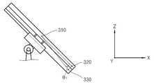
상기 집광판(210)은 태양열을 이용하여 전기에너지를 발전하도록 태양열(광)을 흡수하기 위한 것으로서, 태양위치에 따라서 태양을 추종하도록 상기 구동유닛(220)에 의해 2축 구동된다. 즉, 집광판(210)은 태양의 고도에 따라서 제2축(Y축)을 회전 중심으로 하여 회동 구동되며, 태양의 방향(경도) 위치에 따라서 제1축(X축)을 회전중심으로 하여 회동 구동됨으로써, 집광판(210)의 집광면이 태양광과 수직상태를 유지하도록 하여 채광효율을 최대의 상태로 유지하도록 하게 된다.The
상기 구동유닛(220)은 제1구동부(221)와, 제2구동부(222)를 구비한다. 제1구동부(221)는 집광판(210)을 X축을 중심으로 회동구동시키며, 제2구동부(222)는 집광판(210)을 Y축을 중심으로 회동구동시킨다. 이러한 구동유닛(220)은 메인 제어부(400)에 의해 독립적으로 구동제어된다. 그리고 상기 제1 및 제2구동부(221,222)는 구동모터, 유압실린더 등을 포함하여, 산업전반에서 널리 이용되는 회전구동수단이 적용되어 채용될 수 있으며, 제1 및 제2구동부(221,222)에 의해 본 발명이 한정되는 것은 아니다.The
한편, 더욱 구체적으로는 구동유닛(220)은 초기에는 상기 메인 태양위치 산출부(100)에서 산출된 태양위치값에 따라 집광판(210)이 태양을 추종하도록 메인 제어부(400)에 의해 구동제어된다. 그리고, 추후에는 집광판 위치검출부(300)에서 검출된 집광판(210)의 실제 위치(자세)값에 따라서 집광판(210)의 자세를 보정하도록 구동유닛(220)은 메인제어부(400)에 의해 구동제어된다.On the other hand, more specifically, the
상기 집광판 위치검출부(300)는 집광판(210)의 실제 위치 즉, 태양의 위치에 따라 실제 집광판(210)이 취하고 있는 위치(자세)를 측정하기 위한 것이다. 이러한 집광판 위치검출부(300)는 복수의 GPS 수신부(310,320,330)와, 위치산출부(350)를 구비한다. 복수의 GPS수신부는 제1 내지 제3GPS 수신부(310,320,330)를 포함할 수 있으며, 적어도 2개 이상 구비되어 집광판(210)의 동일 평면상에서 서로 다른 위치에 설치된다. 이러한 제1 내지 제3GPS 수신부(310,320,330)는 GPS위성과의 송/수신을 통해서 각각의 위치값 즉, 좌표값을 획득하게 되고, 그 획득된 각각의 X,Y,Z 좌표값은 위치산출부(350)로 전달된다.The light collecting
그리고 도 2 및 도 3에 도시된 바와 같이, 제1 및 제2GPS 수신부(310,320)는 X축 방향으로 서로 이격되고, Y축 방향으로는 동일 축 선상에 위치되게 설치된다. 그리고 제3GPS 수신부(330)는 X축 방향으로는 제1GPS 수신부(310)와 이격되고, 제2GPS 수신부(320)와는 동일선상에 위치된다. 그리고 제3GPS 수신부(330)는 Y축 방향으로는 제1 및 제2GPS 수신부(310,320) 각각에 대해 이격되게 배치된다.As shown in FIGS. 2 and 3, the first and
따라서 상기 제1 내지 제3GPS 수신부(310,320,330)는 서로 다른 3차원 좌표값을 가지도록 배치된다. 그리고 집광판(210)이 구동유닛(220)의 구동에 의해 위치 즉, 자세가 변하게 되면, 제1 내지 제3GPS 수신부(310,320,330)의 3차원 좌표값들도 변하게 되며, 그 변화된 3차원 좌표값들은 GPS 수신부들(310,320,330) 각각에서 GPS 위성을 통해 획득할 수 있게 된다. 그리고 각 GPS 수신부들(310,320,330)에서 획득된 3차원 좌표값들은 위치산출부(350)로 전송된다.Accordingly, the first to
상기 위치산출부(350)에서는 제1 내지 제3GPS 수신부들(310,320,330) 각각에서 검출된 좌표값들을 근거로 하여 집광판(210)의 실제 위치 즉, 태양 위치를 기준으로 하는 고도 및 경도를 산출하게 된다.The
먼저, 집광판(210)이 Y축을 중심으로 회동 될 경우, 위치산출부(350)에서는 제1 및 제2GPS 수신부(310,320)에서 획득된 좌표값들을 가지고 집광판(210)이 취하고 있는 고도값(θ2)을 구하게 된다. 이는 상기 제1 및 제2GPS 수신부(310,320)간의 거리(d)와, 각 GPS 수신부(310,320)의 좌표값을 획득함으로써 상기 고도값(θ2)을 쉽게 계산하여 산출할 수 있다. 상기 고도값(θ2)은 집광판(210)의 회동각도에 대응하여 변하기 때문에, 실제 집광판(210)의 태양에 대한 상대적인 위치(자세)를 산출할 수 있다.First, when the
또한, 상기 집광판(210)이 도 2의 상태에서 구동유닛(220)의 제어신호에 의해서 도 4와 같이 제1축(X축)을 중심으로 회전되어 태양의 방향을 추종할 경우(이때는 메인 태양위치 산출부에서 산출된 이론적인 추종값에 따라서 동작됨), 집광판(210)이 초기위치에서 회동한 각도에 따라서 제1 및 제3GPS 수신부(310,330) 간의 방향값(θ3)이 변하게 되고, 그 변화된 방향값(θ3)은 제1 및 제3GPS 수신부(310,330)의 실제 좌표값을 획득하여 산출할 수 있게 된다. 즉, 도 2 및 도 3의 초기 상태에서는 방향값 'θ3 = 0'일 경우, 도 4 및 도 5의 상태에서는 방향값 'θ3 = 측정값 =Ø'이 된다.In addition, when the
이와 같이 집광판(210)에 복수의 GPS 수신기(310,320,330)를 설치함으로써, 실제 집광판(210)의 위치와 자세를 위치산출부(350)를 통해 산출할 수 있게 된다.By installing the plurality of
그리고 위치산출부(350)에서 산출된 집광판(210)의 실제위치 정보(측정값)는 상기 메인 제어부(400)로 전달된다.The actual position information (measurement value) of the
상기 메인 제어부(400)는 초기에는 메인 태양위치 산출부(100)에서 산출된 태양위치값(이론값)을 근거로 하여 집광판(210)이 태양을 최적의 상태로 추종하도록 구동유닛(220)을 구동제어하여 집광판(210)의 위치 즉, 자세를 장소, 날짜 및 시간에 따라 태양위치에 맞게 조정한다.The
또한, 메인 제어부(400)는 위치산출부(350)에서 산출되어 전송된 집광판(210)의 실제 위치(자세)에 대한 측정값을 메인 태양위치 산출부(100)에서 산출된 이론값과 비교한다. 그리고 비교 결과 측정값과 이론값에 차이가 있을 경우, 측정값이 이론값과 일치할 수 있도록 구동유닛(220)을 제어하여 집광판(210)의 위치(자세)를 보정하게 된다.In addition, the
따라서, 집광판(210)이 항상 태양위치를 정확하게 추종하여 위치함으로써, 최상의 상태에서 태양열을 흡수할 수 있도록 할 수 있으며, 구동유닛(220)이 오작동하거나 구동오차가 발생하더라도 집광판 위치 검출부(300)에서 그러한 오작동이나 구동오차로 인한 차이값을 검출하여 이를 보정 할 수 있게 된다.Therefore, the
또한, 집광판 위치 검출부(300)에서 검출된 측정값과 이론값의 차이가 지나치게 날 경우 즉, 기준비율(10%) 이상 차이가 날 경우에는, 메인 제어부(400)는 구동유닛(220)의 고장으로 판단하고, 이에 대한 후속조치가 이루어질 수 있도록 한다. 즉, 메인 제어부(400)는 구동유닛(220)의 고장으로 확인될 경우, 미도시 된 송신부를 통해 관리자의 단말기 또는 관리센터의 관리 서버 등으로 구동유닛의 고장발생 정보를 전송함으로써, 관리자 또는 관리센터에서 이를 인지하여 고장을 수리하거나 교체할 수 있도록 할 수 있게 된다.In addition, when the difference between the measured value and the theoretical value detected by the light collecting plate
상기 구성을 가지는 본 발명의 실시예에 따른 태양 위치 추적시스템을 이용한 태양위치 추적방법을 도 1 내지 도 6을 참조하여 자세히 설명하기로 한다.A sun position tracking method using a sun position tracking system according to an embodiment of the present invention having the above configuration will be described in detail with reference to FIGS. 1 to 6.
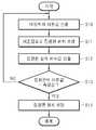
먼저, 메인 태양위치 산출부(100)는 프로그램에 의해 태양 위치값을 이론적으로 산출한다(S10).First, the main sun
상기 메인 태양위치 산출부(100)에서 산출된 이론값은 메인 제어부(400)로 전달되고, 메인 제어부(400)는 전달받은 이론값을 근거로 집광판(210)이 태양을 추종하도록 위치 조정한다(S11).The theoretical value calculated by the main solar
그리고 집광판(210)이 위치조정된 상태에서 상기 집광판 위치검출부(300)에서는 집광판(210)의 실제 위치값을 검출(측정)한다(S12).In the state where the
그리고 상기 집광판 위치검출부(300)에서 검출한 집광판(210)의 실제 위치값 즉, 측정값은 메인 제어부(400)로 전달되고, 메인 제어부(400)는 상기 이론값과 측정값이 일치하는지 비교판단한다(S13).In addition, the actual position value, that is, the measured value of the
상기 단계(S13)에서 비교 결과 이론값과 측정값이 일치하지 않는 경우에는, 메인 제어부(400)는 구동유닛(220)을 구동제어하여 집광판(210)의 실제 위치가 이론값과 동일한 위치 즉, 자세를 갖추도록 위치를 보정한다(S14). 이와 같이 집광판(210)의 위치를 이론값과 일치하도록 보정함으로써, 구동유닛(220)의 고장이나 오동작, 구동유닛(220)의 구동오차가 발생하더라도 집광판(210)이 항상 태양을 정확하게 추종하도록 제어할 수 있게 된다.When the theoretical value and the measured value are not the same as the result of the comparison in the step S13, the
또한, 집광판(210)의 설치위치 정보와, 날짜 및 시간 정보를 알 수 있기 때문에, 일출시간부터 일몰시간까지의 정확한 시간이 확보되어 집광판(210) 및 구동유닛(220)의 구동시간을 제한하여 제어함으로써, 일몰시간부터 일출시간 전까지는 구동유닛(220) 및 집광판(210)에 대한 제어를 멈추게 되고, 따라서 그에 따른 관리비용과 유지비용을 절감할 수 있게 된다.In addition, since the installation position information and the date and time information of the
또한, 앞서 설명한 바와 같이, 집광판(210)에 설치되는 집광판 위치검출부(300)를 이용하여 집광판(210)의 실제 위치(자세)를 검출할 수 있게 됨으로써, 측정값과 이론값을 상호 비교하여 실제 집광판(210)이 제어신호에 따라 위치제어되는지 여부를 판단할 수 있으며 차이가 발생할 경우 이를 보정함으로써 집광판(210)이 항상 태양을 정확하게 추종하도록 제어할 수 있게 되며, 태양열을 이용한 전력생산 효율을 극대화할 수 있는 이점이 있다.In addition, as described above, the actual position (posture) of the
이상, 본 발명을 본 발명의 원리를 예시하기 위한 바람직한 실시예와 관련하여 도시하고 설명하였으나, 본 발명은 그와 같이 도시되고 설명된 그대로의 구성 및 작용으로 한정되는 것이 아니다. 오히려 첨부된 특허청구범위의 사상 및 범위를 일탈함이 없이 본 발명에 대한 다수의 변경 및 수정이 가능함을 당업자들은 잘 이해할 수 있을 것이다.
While the invention has been shown and described in connection with preferred embodiments for illustrating the principles of the invention, the invention is not limited to the construction and operation as shown and described. Those skilled in the art will readily appreciate that many modifications and variations of the present invention are possible without departing from the spirit and scope of the appended claims.
100..메인 태양위치 산출부 110..입력부
210..집광판 220..구동유닛
300..집광판 위치검출부 310,320,330..제1 내지 제3GPS 수신부
350..위치산출부 400..메인 제어부100. Main solar
210. Condensing
300. Condenser plate
350.
Claims (3)
Translated fromKorean상기 집광판을 2축 방향으로 각각 회동시켜 태양을 추종하도록 하는 구동유닛과;
프로그램을 이용하여 상기 집광판의 위치를 기준으로 태양 위치를 이론적으로 계산하여 산출하는 메인 태양위치 산출부와;
상기 집광판의 상기 태양을 기준으로 한 실제 위치(자세)를 측정하기 위한 집광판 위치검출부; 및
상기 메인 태양위치 산출부에서 산출된 이론값에 의해 상기 구동유닛을 구동제어하여 상기 집광판의 위치를 조정하고, 위치 조정된 집광판에 대한 위치 측정값을 상기 집광판 위치검출부로부터 전달받아 상기 이론값과 비교하며, 상기 이론값과 측정값의 차이만큼 상기 집광판의 위치를 보정하여 조정하도록 제어하는 메인 제어부;를 포함하며,
상기 집광판 위치검출부는,
상기 집광판에서 서로 다른 위치에 각각 설치되며, GPS 위성으로부터 각각의 위치정보를 획득하는 복수의 GPS 수신기와;
상기 복수의 GPS 수신기에서 획득된 좌표값을 근거로 하여 상기 집광판의 실제 위치(자세)를 산출하는 위치산출부;를 포함하는 것을 태양 위치 추적시스템.A light collecting plate for receiving sunlight;
A drive unit which rotates the light collecting plates in two axial directions to follow the sun;
A main solar position calculator for calculating and calculating a solar position based on the position of the light collecting plate using a program;
A light collecting plate position detector for measuring an actual position (posture) of the light collecting plate with respect to the sun; And
The driving unit is controlled by the theoretical value calculated by the main solar position calculating unit to adjust the position of the light collecting plate, and the position measurement value for the adjusted light collecting plate is received from the light collecting plate position detecting unit and compared with the theoretical value. And a main controller configured to control to correct and adjust the position of the light collecting plate by a difference between the theoretical value and the measured value.
The light collecting plate position detection unit,
A plurality of GPS receivers respectively installed at different positions in the light collecting plate and obtaining respective position information from GPS satellites;
And a position calculator configured to calculate an actual position (posture) of the light collecting plate based on the coordinate values acquired by the plurality of GPS receivers.
상기 집광판의 중앙에 배치되는 제1GPS 수신기와;
상기 제1GPS 수신기와는 제1축(X) 방향으로는 서로 이격되고 제2축(Y) 방향으로는 상기 제1GPS 수신기와는 동일선상에 위치하도록 상기 집광판에 설치되는 제2GPS 수신기; 및
상기 제1GPS 수신기와는 제1축(X) 및 제2축(Y) 방향 각각으로 이격되고, 상기 제2GPS 수신기와는 제2축(Y) 방향으로만 이격되게 상기 집광판의 모서리부분에 배치되는 제3GPS 수신기;를 포함하는 것을 특징으로 하는 태양 위치 추적시스템.
The method of claim 1, wherein the plurality of GPS receivers,
A first GPS receiver disposed at the center of the light collecting plate;
A second GPS receiver installed on the light collecting plate so that the first GPS receiver is spaced apart from each other in a first axis (X) direction and is in the same line as the first GPS receiver in a second axis (Y) direction; And
The first GPS receiver is spaced apart from each other in the first axis (X) and second axis (Y) directions, and the second GPS receiver is disposed at an edge portion of the light collecting plate so as to be spaced apart only in the second axis (Y) direction. And a third GPS receiver.
Applications Claiming Priority (2)
| Application Number | Priority Date | Filing Date | Title |
|---|---|---|---|
| KR1020100019193 | 2010-03-03 | ||
| KR20100019193 | 2010-03-03 |
Publications (2)
| Publication Number | Publication Date |
|---|---|
| KR20110100128A KR20110100128A (en) | 2011-09-09 |
| KR101220321B1true KR101220321B1 (en) | 2013-01-11 |
Family
ID=44952739
Family Applications (1)
| Application Number | Title | Priority Date | Filing Date |
|---|---|---|---|
| KR1020100117712AExpired - Fee RelatedKR101220321B1 (en) | 2010-03-03 | 2010-11-24 | A sun location tracking system |
Country Status (1)
| Country | Link |
|---|---|
| KR (1) | KR101220321B1 (en) |
Cited By (1)
| Publication number | Priority date | Publication date | Assignee | Title |
|---|---|---|---|---|
| KR102473192B1 (en)* | 2021-06-03 | 2022-12-01 | 박찬종 | Solar power generation system that controls solar tracking by analyzing big data using artificial neural network |
Families Citing this family (3)
| Publication number | Priority date | Publication date | Assignee | Title |
|---|---|---|---|---|
| KR101336869B1 (en)* | 2012-03-27 | 2013-12-04 | 보성파워텍 주식회사 | Bracket for solar generating module |
| JP5763109B2 (en)* | 2012-04-23 | 2015-08-12 | 太陽光電能源科技股▲ふん▼有限公司Big Sun Energy Technology Inc. | Automatic solar tracking adjustment control device for photovoltaic generator unit |
| CN104238577B (en)* | 2014-09-24 | 2017-02-15 | 上海律邦新能源科技有限公司 | Biaxial computer-numerical-control positioning method and system of solar panels |
Citations (4)
| Publication number | Priority date | Publication date | Assignee | Title |
|---|---|---|---|---|
| JP2001210116A (en) | 2000-01-28 | 2001-08-03 | Matsushita Electric Works Ltd | Solar light collecting device |
| KR100483291B1 (en)* | 2001-01-04 | 2005-04-15 | 박상규 | Method of control solar position pursuit |
| KR20090125995A (en)* | 2008-06-03 | 2009-12-08 | 서대호 | Solar tracking method and tracking device |
| JP2010016331A (en) | 2008-07-02 | 2010-01-21 | Sunplus Mmedia Inc | Solar tracking device and tracking method thereof |
- 2010
- 2010-11-24KRKR1020100117712Apatent/KR101220321B1/ennot_activeExpired - Fee Related
Patent Citations (4)
| Publication number | Priority date | Publication date | Assignee | Title |
|---|---|---|---|---|
| JP2001210116A (en) | 2000-01-28 | 2001-08-03 | Matsushita Electric Works Ltd | Solar light collecting device |
| KR100483291B1 (en)* | 2001-01-04 | 2005-04-15 | 박상규 | Method of control solar position pursuit |
| KR20090125995A (en)* | 2008-06-03 | 2009-12-08 | 서대호 | Solar tracking method and tracking device |
| JP2010016331A (en) | 2008-07-02 | 2010-01-21 | Sunplus Mmedia Inc | Solar tracking device and tracking method thereof |
Cited By (1)
| Publication number | Priority date | Publication date | Assignee | Title |
|---|---|---|---|---|
| KR102473192B1 (en)* | 2021-06-03 | 2022-12-01 | 박찬종 | Solar power generation system that controls solar tracking by analyzing big data using artificial neural network |
Also Published As
| Publication number | Publication date |
|---|---|
| KR20110100128A (en) | 2011-09-09 |
Similar Documents
| Publication | Publication Date | Title |
|---|---|---|
| AU2011279154B2 (en) | Robotic heliostat system and method of operation | |
| KR101267007B1 (en) | A sun location tracking system for electric car | |
| KR101053187B1 (en) | Solar tracking system | |
| KR101220321B1 (en) | A sun location tracking system | |
| US20130048829A1 (en) | Solar concentrator positioning system and method | |
| KR20080013481A (en) | Tracking Solar Power Unit | |
| KR100948288B1 (en) | Sunlight tracker and sunlight tracking system for large-scale sunlight generating station having the sunlight tracker | |
| KR101802370B1 (en) | Apparatus for solar energy generation | |
| US20130019920A1 (en) | Combination solar cell sun sensor for direct alignment of trackers and closed-loop tracking | |
| CN102929298A (en) | Tower-type solar heat collection heliostat field control system based on multi-layer architecture | |
| US20110158467A1 (en) | Solar power device | |
| KR20080058301A (en) | Tracking solar power system operation control method | |
| US20140202521A1 (en) | Self-powered solar tracker | |
| KR20130092020A (en) | Control mehtod for solar photovaltaic generating system improving generation efficiency | |
| KR101652243B1 (en) | Solar sensor and solar tracker including the solar sensor | |
| CN101777856B (en) | Photovoltaic tracking device using photosensitive difference and network-based monitoring method | |
| KR101220319B1 (en) | An electric car having a sun location tracking system | |
| KR101312096B1 (en) | A solar tracking apparatus | |
| KR101003465B1 (en) | Solar tracking device and web-based solar tracking monitoring control method using projection shadow | |
| KR101220322B1 (en) | A system for tracking sun location | |
| KR101085172B1 (en) | Solar tracker | |
| KR101318417B1 (en) | A solar tracking apparatus | |
| JPWO2019082589A1 (en) | Solar power system | |
| KR102114817B1 (en) | tracked solar photovoltaic system | |
| KR101312095B1 (en) | A solar tracking apparatus |
Legal Events
| Date | Code | Title | Description |
|---|---|---|---|
| A201 | Request for examination | ||
| PA0109 | Patent application | St.27 status event code:A-0-1-A10-A12-nap-PA0109 | |
| PA0201 | Request for examination | St.27 status event code:A-1-2-D10-D11-exm-PA0201 | |
| P11-X000 | Amendment of application requested | St.27 status event code:A-2-2-P10-P11-nap-X000 | |
| P13-X000 | Application amended | St.27 status event code:A-2-2-P10-P13-nap-X000 | |
| PG1501 | Laying open of application | St.27 status event code:A-1-1-Q10-Q12-nap-PG1501 | |
| D13-X000 | Search requested | St.27 status event code:A-1-2-D10-D13-srh-X000 | |
| D14-X000 | Search report completed | St.27 status event code:A-1-2-D10-D14-srh-X000 | |
| E902 | Notification of reason for refusal | ||
| PE0902 | Notice of grounds for rejection | St.27 status event code:A-1-2-D10-D21-exm-PE0902 | |
| N231 | Notification of change of applicant | ||
| PN2301 | Change of applicant | St.27 status event code:A-3-3-R10-R13-asn-PN2301 St.27 status event code:A-3-3-R10-R11-asn-PN2301 | |
| R17-X000 | Change to representative recorded | St.27 status event code:A-3-3-R10-R17-oth-X000 | |
| E13-X000 | Pre-grant limitation requested | St.27 status event code:A-2-3-E10-E13-lim-X000 | |
| P11-X000 | Amendment of application requested | St.27 status event code:A-2-2-P10-P11-nap-X000 | |
| P13-X000 | Application amended | St.27 status event code:A-2-2-P10-P13-nap-X000 | |
| E701 | Decision to grant or registration of patent right | ||
| PE0701 | Decision of registration | St.27 status event code:A-1-2-D10-D22-exm-PE0701 | |
| GRNT | Written decision to grant | ||
| PR0701 | Registration of establishment | St.27 status event code:A-2-4-F10-F11-exm-PR0701 | |
| PR1002 | Payment of registration fee | St.27 status event code:A-2-2-U10-U11-oth-PR1002 Fee payment year number:1 | |
| PG1601 | Publication of registration | St.27 status event code:A-4-4-Q10-Q13-nap-PG1601 | |
| P22-X000 | Classification modified | St.27 status event code:A-4-4-P10-P22-nap-X000 | |
| LAPS | Lapse due to unpaid annual fee | ||
| PC1903 | Unpaid annual fee | St.27 status event code:A-4-4-U10-U13-oth-PC1903 Not in force date:20160104 Payment event data comment text:Termination Category : DEFAULT_OF_REGISTRATION_FEE | |
| P22-X000 | Classification modified | St.27 status event code:A-4-4-P10-P22-nap-X000 | |
| PC1903 | Unpaid annual fee | St.27 status event code:N-4-6-H10-H13-oth-PC1903 Ip right cessation event data comment text:Termination Category : DEFAULT_OF_REGISTRATION_FEE Not in force date:20160104 | |
| P22-X000 | Classification modified | St.27 status event code:A-4-4-P10-P22-nap-X000 | |
| P22-X000 | Classification modified | St.27 status event code:A-4-4-P10-P22-nap-X000 | |
| P22-X000 | Classification modified | St.27 status event code:A-4-4-P10-P22-nap-X000 |