KR101220204B1 - Light Emitting Diodes back-light assembly and liquid crystal display device module using thereof - Google Patents
Light Emitting Diodes back-light assembly and liquid crystal display device module using thereofDownload PDFInfo
- Publication number
- KR101220204B1 KR101220204B1KR1020050131721AKR20050131721AKR101220204B1KR 101220204 B1KR101220204 B1KR 101220204B1KR 1020050131721 AKR1020050131721 AKR 1020050131721AKR 20050131721 AKR20050131721 AKR 20050131721AKR 101220204 B1KR101220204 B1KR 101220204B1
- Authority
- KR
- South Korea
- Prior art keywords
- leds
- liquid crystal
- backlight assembly
- led backlight
- led
- Prior art date
- Legal status (The legal status is an assumption and is not a legal conclusion. Google has not performed a legal analysis and makes no representation as to the accuracy of the status listed.)
- Active
Links
Images


Classifications
- G—PHYSICS
- G02—OPTICS
- G02F—OPTICAL DEVICES OR ARRANGEMENTS FOR THE CONTROL OF LIGHT BY MODIFICATION OF THE OPTICAL PROPERTIES OF THE MEDIA OF THE ELEMENTS INVOLVED THEREIN; NON-LINEAR OPTICS; FREQUENCY-CHANGING OF LIGHT; OPTICAL LOGIC ELEMENTS; OPTICAL ANALOGUE/DIGITAL CONVERTERS
- G02F1/00—Devices or arrangements for the control of the intensity, colour, phase, polarisation or direction of light arriving from an independent light source, e.g. switching, gating or modulating; Non-linear optics
- G02F1/01—Devices or arrangements for the control of the intensity, colour, phase, polarisation or direction of light arriving from an independent light source, e.g. switching, gating or modulating; Non-linear optics for the control of the intensity, phase, polarisation or colour
- G02F1/13—Devices or arrangements for the control of the intensity, colour, phase, polarisation or direction of light arriving from an independent light source, e.g. switching, gating or modulating; Non-linear optics for the control of the intensity, phase, polarisation or colour based on liquid crystals, e.g. single liquid crystal display cells
- G02F1/133—Constructional arrangements; Operation of liquid crystal cells; Circuit arrangements
- G02F1/1333—Constructional arrangements; Manufacturing methods
- G02F1/1335—Structural association of cells with optical devices, e.g. polarisers or reflectors
- G02F1/1336—Illuminating devices
- G02F1/133602—Direct backlight
- G02F1/133603—Direct backlight with LEDs
- G—PHYSICS
- G02—OPTICS
- G02F—OPTICAL DEVICES OR ARRANGEMENTS FOR THE CONTROL OF LIGHT BY MODIFICATION OF THE OPTICAL PROPERTIES OF THE MEDIA OF THE ELEMENTS INVOLVED THEREIN; NON-LINEAR OPTICS; FREQUENCY-CHANGING OF LIGHT; OPTICAL LOGIC ELEMENTS; OPTICAL ANALOGUE/DIGITAL CONVERTERS
- G02F1/00—Devices or arrangements for the control of the intensity, colour, phase, polarisation or direction of light arriving from an independent light source, e.g. switching, gating or modulating; Non-linear optics
- G02F1/01—Devices or arrangements for the control of the intensity, colour, phase, polarisation or direction of light arriving from an independent light source, e.g. switching, gating or modulating; Non-linear optics for the control of the intensity, phase, polarisation or colour
- G02F1/13—Devices or arrangements for the control of the intensity, colour, phase, polarisation or direction of light arriving from an independent light source, e.g. switching, gating or modulating; Non-linear optics for the control of the intensity, phase, polarisation or colour based on liquid crystals, e.g. single liquid crystal display cells
- G02F1/133—Constructional arrangements; Operation of liquid crystal cells; Circuit arrangements
- G02F1/1333—Constructional arrangements; Manufacturing methods
- G02F1/1335—Structural association of cells with optical devices, e.g. polarisers or reflectors
- G02F1/1336—Illuminating devices
- G02F1/133602—Direct backlight
- G02F1/133605—Direct backlight including specially adapted reflectors
- G—PHYSICS
- G02—OPTICS
- G02F—OPTICAL DEVICES OR ARRANGEMENTS FOR THE CONTROL OF LIGHT BY MODIFICATION OF THE OPTICAL PROPERTIES OF THE MEDIA OF THE ELEMENTS INVOLVED THEREIN; NON-LINEAR OPTICS; FREQUENCY-CHANGING OF LIGHT; OPTICAL LOGIC ELEMENTS; OPTICAL ANALOGUE/DIGITAL CONVERTERS
- G02F1/00—Devices or arrangements for the control of the intensity, colour, phase, polarisation or direction of light arriving from an independent light source, e.g. switching, gating or modulating; Non-linear optics
- G02F1/01—Devices or arrangements for the control of the intensity, colour, phase, polarisation or direction of light arriving from an independent light source, e.g. switching, gating or modulating; Non-linear optics for the control of the intensity, phase, polarisation or colour
- G02F1/13—Devices or arrangements for the control of the intensity, colour, phase, polarisation or direction of light arriving from an independent light source, e.g. switching, gating or modulating; Non-linear optics for the control of the intensity, phase, polarisation or colour based on liquid crystals, e.g. single liquid crystal display cells
- G02F1/133—Constructional arrangements; Operation of liquid crystal cells; Circuit arrangements
- G02F1/1333—Constructional arrangements; Manufacturing methods
- G02F1/1335—Structural association of cells with optical devices, e.g. polarisers or reflectors
- G02F1/1336—Illuminating devices
- G02F1/133602—Direct backlight
- G02F1/133609—Direct backlight including means for improving the color mixing, e.g. white
- G—PHYSICS
- G02—OPTICS
- G02F—OPTICAL DEVICES OR ARRANGEMENTS FOR THE CONTROL OF LIGHT BY MODIFICATION OF THE OPTICAL PROPERTIES OF THE MEDIA OF THE ELEMENTS INVOLVED THEREIN; NON-LINEAR OPTICS; FREQUENCY-CHANGING OF LIGHT; OPTICAL LOGIC ELEMENTS; OPTICAL ANALOGUE/DIGITAL CONVERTERS
- G02F1/00—Devices or arrangements for the control of the intensity, colour, phase, polarisation or direction of light arriving from an independent light source, e.g. switching, gating or modulating; Non-linear optics
- G02F1/01—Devices or arrangements for the control of the intensity, colour, phase, polarisation or direction of light arriving from an independent light source, e.g. switching, gating or modulating; Non-linear optics for the control of the intensity, phase, polarisation or colour
- G02F1/13—Devices or arrangements for the control of the intensity, colour, phase, polarisation or direction of light arriving from an independent light source, e.g. switching, gating or modulating; Non-linear optics for the control of the intensity, phase, polarisation or colour based on liquid crystals, e.g. single liquid crystal display cells
- G02F1/133—Constructional arrangements; Operation of liquid crystal cells; Circuit arrangements
- G02F1/1333—Constructional arrangements; Manufacturing methods
- G02F1/1335—Structural association of cells with optical devices, e.g. polarisers or reflectors
- G02F1/1336—Illuminating devices
- G02F1/133602—Direct backlight
- G02F1/133611—Direct backlight including means for improving the brightness uniformity
- Y—GENERAL TAGGING OF NEW TECHNOLOGICAL DEVELOPMENTS; GENERAL TAGGING OF CROSS-SECTIONAL TECHNOLOGIES SPANNING OVER SEVERAL SECTIONS OF THE IPC; TECHNICAL SUBJECTS COVERED BY FORMER USPC CROSS-REFERENCE ART COLLECTIONS [XRACs] AND DIGESTS
- Y10—TECHNICAL SUBJECTS COVERED BY FORMER USPC
- Y10S—TECHNICAL SUBJECTS COVERED BY FORMER USPC CROSS-REFERENCE ART COLLECTIONS [XRACs] AND DIGESTS
- Y10S362/00—Illumination
- Y10S362/80—Light emitting diode
Landscapes
- Physics & Mathematics (AREA)
- Nonlinear Science (AREA)
- Mathematical Physics (AREA)
- Chemical & Material Sciences (AREA)
- Crystallography & Structural Chemistry (AREA)
- General Physics & Mathematics (AREA)
- Optics & Photonics (AREA)
- Liquid Crystal (AREA)
- Planar Illumination Modules (AREA)
- Led Device Packages (AREA)
Abstract
Translated fromKoreanDescription
Translated fromKorean도 1은 일반적인 액정표시장치모듈의 분해 사시도.1 is an exploded perspective view of a general LCD module;
도 2는 일반적인 액정표시장치모듈의 일부 단면도.2 is a partial cross-sectional view of a typical liquid crystal display module.
도 3은 본 발명에 따른 액정표시장치모듈의 분해 사시도.3 is an exploded perspective view of a liquid crystal display module according to the present invention.
도 4는 본 발명에 따른 반사시트의 격자구조에 대한 확대사시도.Figure 4 is an enlarged perspective view of the lattice structure of the reflective sheet according to the present invention.
도 5는 본 발명에 따른 반사시트의 격자구조에 대한 변형예를 나타낸 확대사시도.5 is an enlarged perspective view showing a modification of the lattice structure of the reflective sheet according to the present invention.
도 6은 본 발명에 따른 액정표시장치모듈의 변형예를 나타낸 분해 사시도.6 is an exploded perspective view showing a modification of the liquid crystal display module according to the present invention.
도 7a 내지 도 7i는 각각 본 발명에 따른 LED의 배치예를 나타낸 평면도.7A to 7I are plan views showing examples of arrangement of LEDs according to the present invention, respectively.
<도면의 주요부분에 대한 부호의 설명><Description of the symbols for the main parts of the drawings>
110 : 액정패널112,114 : 제 1 및 제 2 기판110:
116 : TCP120 : LED 백라이트어셈블리116: TCP 120: LED backlight assembly
122 : 인쇄회로기판124 : LED122: printed circuit board 124: LED
130 : 반사시트132 : 관통홀130: reflective sheet 132: through hole
134 : 격벽부재138 : 격자구조134: partition member 138: lattice structure
148 : 광학시트150 : 서포트메인148: Optical sheet 150: Support main
160 : 커버버툼170 : 탑커버160: Cover Bottom 170: Top Cover
본 발명은 LED(Light Emitting Diode : LED) 백라이트어셈블리(back-light assembly) 및 이를 이용한 액정표시장치모듈(liquid crystal display module)에 관한 것으로, 보다 구체적으로는 다수의 LED를 광원(光源)으로 채택한 직하형(direct type)의 LED 백라이트어셈블리 및 이로부터 출사된 광을 이용해서 여러 가지 화상을 구현할 수 있도록 액정패널(liquid crystal panel)과 함께 일체화된 액정표시장치모듈에 관한 것이다.BACKGROUND OF THE INVENTION 1. Field of the Invention The present invention relates to a light emitting diode (LED) backlight assembly and a liquid crystal display module using the same. More specifically, a plurality of LEDs are employed as a light source. The present invention relates to a liquid crystal display module integrated with a liquid crystal panel so as to implement various images using a direct type LED backlight assembly and light emitted therefrom.
현대의 본격적인 정보화 시대에 발맞추어 전기적 신호를 통해 화상을 표시하는 디스플레이(display) 분야 또한 급속도로 발전해왔고, 이에 부응하여 경박단소(輕薄短小)와 저소비전력화 특징을 지닌 평판표시장치(Flat Panel Display device : FPD)로서, 액정표시장치(Liquid Crystal Display device: LCD), 플라즈마표시장치(Plasma Display Panel device: PDP), 전계방출표시장치(Field Emission Display device: FED), 전기발광표시장치(Electro luminescence Display device : ELD) 등이 소개되어 기존의 브라운관(Cathode Ray Tube : CRT)을 빠르게 대체하고 있다.In line with the modern era of informatization, the display field for displaying images through electrical signals has also been rapidly developed. In response, the flat panel display device with light and small size and low power consumption has been developed. : FPD: Liquid Crystal Display Device (LCD), Plasma Display Panel Device (PDP), Field Emission Display Device (FED), Electroluminescence Display (Electro luminescence Display) Device (ELD) has been introduced to quickly replace the existing Cathode Ray Tube (CRT).
이중에서도 액정표시장치는 동화상 표시에 우수하고 대조비(contrast ratio)가 큰 특징을 보여 모니터, TV 등의 분야에서 가장 활발하게 이용되고 있는데, 이는 액정의 광학적 이방성(optical anisotropy)과 분극성질(polarization)을 이용한 화상구현원리를 나타내는바, 주지된 내용으로서 액정은 분자구조가 가늘고 길며 배열에 방향성을 갖는 광학적 이방성과 전기장 내에 놓일 경우 그 크기에 따라 분자의 배열방향이 변화되는 분극성질을 띤다.Among them, the liquid crystal display device is excellent in moving image display and has a high contrast ratio, and thus is used most actively in the fields of monitors and TVs, which are used for optical anisotropy and polarization of liquid crystals. As the well-known contents, the liquid crystal has a thin and long molecular structure, and has an optical anisotropy having an orientation in an array and a polarization property in which the arrangement direction of the molecules changes depending on its size when placed in an electric field.
이에 따라 일반적인 액정표시장치는 나란한 두 기판 사이로 액정층을 개재하여 합착시킨 액정패널(liquid crystal panel)을 필수적인 구성요소로 하며, 액정패널 내부의 전기장 크기에 따라 액정분자의 배열방향을 인위적으로 조절해서 빛의 투과율을 변화시킨다. 하지만 액정패널은 자체 발광요소를 갖추지 못한 관계로 투과율 변화를 외부로 투영시킬 수 있는 별도의 조광수단을 요구하고, 이를 위해 액정패널 배면으로는 광원(光源)이 내장된 백라이트어셈블리(back-light assembly)가 배치되어 빛을 공급한다.Accordingly, a general liquid crystal display device is an essential component of a liquid crystal panel bonded through a liquid crystal layer between two side-by-side substrates, and artificially adjusts the arrangement direction of liquid crystal molecules according to the electric field size inside the liquid crystal panel. Change the transmittance of light. However, since the liquid crystal panel does not have a self-luminous element, it requires a separate dimming means for projecting a change in transmittance to the outside. ) Is placed to supply light.
이때 백라이트어셈블리의 광원으로는 전통적으로 외부전극형광램프(Exterior Electrode Fluorescent Lamp : EEFL)나 냉음극형광램프(Cold Cathode Fluorescent Lamp : CCFL) 등의 수은방전램프가 사용되었지만, 최근 들어 유독성의 수은(Ag)을 사용하지 않으면서 색재현성을 향상시킬 수 있는 LED(Light Emitting Diode)를 이용하는 경우가 늘고 있으며, 이와 같이 LED를 광원으로 이용하는 경우를 특히 LED 백라이트어셈블리라 한다.At this time, mercury discharge lamps such as external electrode fluorescent lamps (EEFL) and cold cathode fluorescent lamps (CCFL) have traditionally been used as the light source of the backlight assembly. Increasingly, LEDs (Light Emitting Diodes) that can improve color reproducibility without the use of) are increasingly used, and the use of LEDs as a light source is called LED backlight assembly.
한편, 일반적으로 백라이트어셈블리는 빛을 발하는 광원의 위치에 따라 측광 형(side light type)과 직하형(direct type)으로 구분되며, 전자의 측광형은 액정패널에 대해 이의 후방 적어도 일 측면에 배치된 광원의 빛을 별도의 도광판(Light Guide Panel : LGP)으로 굴절시켜 액정패널로 공급하는 반면, 후자의 직하형은 액정패널 배면에 복수의 광원을 배치하여 직접적인 빛을 공급한다.On the other hand, the backlight assembly is generally divided into a side light type and a direct type according to the position of the light source emitting light, and the former light metering type is disposed on at least one side of the rear side of the liquid crystal panel. While the light of the light source is refracted by a separate light guide panel (LGP) to be supplied to the liquid crystal panel, the latter direct type supplies direct light by arranging a plurality of light sources on the back of the liquid crystal panel.
첨부된 도 1은 일반적인 직하형의 LED 백라이트어셈블리(20)를 이용한 액정표시장치에 대한 분해사시도로서, 액정패널(10)과 LED 백라이트어셈블리(20)는 통상 충격으로부터의 보호와 광 손실의 최소화를 위해 각종 기계적 요소에 의해 일체화되는바, 이하 액정표시장치모듈(liquid crystal display module)이라 총칭하면, 이는 상하로 포개어지는 액정패널(10) 및 LED 백라이트어셈블리(20)와, 이들의 가장자리를 테두리하는 서포트메인(support main : 40)과, LED 백라이트어셈블리(20)의 배면을 덮어 서포트메인(40)에 결합되는 커버버툼(cover bottom : 50) 그리고 액정패널(10)의 전면 가장자리를 테두리하며 서포트메인(40)을 매개로 커버버툼(50)과 조립되는 탑커버(top cover : 60)를 포함한다.1 is an exploded perspective view of a liquid crystal display device using a general direct-type
그리고 이중 LED 백라이트어셈블리(20)는 커버버툼(50) 내면에 스트라이프(stripe) 형태로 배열 고정되는 복수개의 인쇄회로기판(Printed Circuit Board : PCB)(22) 및 이들 각각에 열을 지어 탑재된 다수의 LED(24)와, 각각의 LED(24)가 통과할 수 있는 복수개의 관통홀(28)이 투공되어 LED(24)를 제외한 인쇄회로기판(22)과 커버버툼(50) 내면을 덮어 가리는 백색 또는 은색의 반사시트(reflector sheet : 26)와, 이의 상부에서 다수의 LED(24)와 일정간격을 두고 액정패널(10)과 의 사이로 개재되는 복수 매의 광학시트(32)를 포함한다.In addition, the dual
이때 다수의 LED(24)는 R(red), G(green), B(blue) 컬러광을 각각 발하는 RGB LED(24)를 일정규칙에 따라 배열하여 색섞임(color mixing)에 의한 백색광을 구현하는 것이 일반적이고, 복수 매의 광학시트(32)는 확산시트(diffuser sheet)를 비롯한 프리즘시트(prism sheet) 등을 포함한다.In this case, the plurality of
다음으로 도 2는 앞서 설명한 일반적인 액정표시장치모듈 일부에 대한 단면도로서, 도 1의 액정표시장치모듈을 결합한 후 여기에 표시된 II-II 선을 따라 절단한 단면에 해당된다.Next, FIG. 2 is a cross-sectional view of a portion of the general liquid crystal display module described above, and corresponds to a cross section taken along the line II-II shown here after combining the liquid crystal display module of FIG. 1.
이를 도 1과 비교하면 상술한 각 구성요소를 확인할 수 있으며, 다수의 LED(24)로부터 출사된 빛은 직접 또는 반사시트(26)에 의해 반사되어 광학시트(32)를 통과한 후 액정패널(10)로 입사되고, 이로써 액정패널(10)은 외부로 화상을 표시할 수 있다.Compared with FIG. 1, each of the above-described components can be identified, and the light emitted from the plurality of
그러나 일반적인 LED 백라이트어셈블리(20)는 몇 가지 단점을 드러내는데, LED(24)의 광 효율이 형광램프 대비 1/3 정도 수준에 머무르고 있어 전체적인 휘도가 낮고, 때문에 동일 휘도의 표시화면을 구현하기 위해서는 LED(24)의 갯수를 늘려야 하지만 이로 인한 재료비의 상승과 소비전력 증가를 수반하는 단점이 있다.However, the general
구체적인 예로서 20인치 이상의 TV 또는 모니터용 액정표시장치를 살펴보면, 유사수준의 재료비와 소비전력을 소모한다는 전제 하에 형광램프의 사이 간격이 20 내지 25mm 정도일 경우에 LED(24)의 열 사이 간격은 65 내지 100mm 정도가 되고, 해당 간격에서는 열 사이사이를 따라 상대적으로 휘도가 낮은 암선이 출현한다.As a specific example, looking at a liquid crystal display for a TV or monitor of 20 inches or more, if the distance between the fluorescent lamps is about 20 to 25 mm on the premise of consuming similar material costs and power consumption, the interval between the columns of the
아울러 일반적인 LED 백라이트어셈블리(20)는 이른바 분할구동에 매우 취약한 단점을 나타내는데, 분할구동이란 폭파장면과 같이 표시화면 일부에서만 상대적으로 강한 고휘도를 표시하고자 해당 부분의 광원만을 발광시켜 대조비를 높이는 방법을 일컫는다.In addition, the general
반면, 일반적인 LED 백라이트어셈블리(20)에서 가장 중요시되는 부분 중 하나는 RGB LED(24) 각각으로부터 출사된 RGB 컬러광을 액정패널(10)에 도달하기 전에 충분히 색섞임 시키는 것으로서, 이를 위해 앞서 언급된 바와 같이 스트라이프 형상의 인쇄회로기판(22) 상에 다수의 LED(24)가 일정 피치(pitch)로 열을 지어 배열되는 구조를 나타내는 것이며, 이와는 별도로 LED(24)의 주 출사각을 가급적이면 측방으로 확대시키려는 노력과 함께 충분한 색섞임 공간이 확보되도록 LED(24)와 광학시트(32) 사이간격은 필히 일정간격 이상으로 보장되어야 하고, 더 나아가 LED(24)와 광학시트(32) 사이로 별도의 확산부재를 개입시키는 등의 다양한 확산설계구조를 채택하고 있다.On the other hand, one of the most important parts of the general
하지만 이러한 여러 가지 확산설계구조는 휘도 저하의 또 다른 원인이 됨과 동시에 일부 LED(24) 만을 발광시킨다 할지라도 경계가 뚜렷하지 못하여 강한 대조비를 얻기 힘들고, 이에 따라 분할구동에는 취약한 단점을 보이고 있다.However, these various diffusion design structures are another cause of the deterioration of brightness and at the same time, even if only some of the
이에 본 발명은 상기와 같은 문제점을 해결하기 위하여 안출된 것으로, LED 백라이트어셈블리의 전체적인 휘도 상승과 더불어 LED 열 사이에서 나타나는 부분적인 휘도저하 현상을 해소하며, RGB 컬러광의 색섞임을 충분하게 보장함은 물론 분할구동에 적합한 LED 백라이트어셈블리 및 이를 이용한 액정표시장치모듈을 제공하는데 그 목적이 있다.Accordingly, the present invention has been made to solve the above problems, and solves the partial brightness deterioration phenomenon that occurs between the LED columns and the overall brightness of the LED backlight assembly, and ensures sufficient color mixing of RGB color light Of course, an object of the present invention is to provide an LED backlight assembly suitable for split driving and a liquid crystal display module using the same.
본 발명은 상기와 같은 목적을 달성하기 위하여, 전방으로 빛을 발하는 복수개의 LED와; 상기 복수개의 LED를 상면으로부터 노출시키도록 일대일 대응되는 복수개의 관통홀이 투공되고, 상기 상면에서 서로 교차되어 상기 복수개의 LED를 수 개 단위로 구획하는 격자구조를 제공하는 격벽부재가 구비된 반사시트를 포함하는 LED 백라이트어셈블리를 제공한다.The present invention to achieve the above object, a plurality of LEDs emitting light forward; Reflective sheet provided with a partition member for providing a lattice structure that a plurality of through holes corresponding to the one to one corresponding to expose the plurality of LEDs from the upper surface, and cross each other on the upper surface to partition the plurality of LEDs by several units It provides an LED backlight assembly comprising a.
이때 상기 격벽부재는 길이방향에 수직한 단면형상이 삼각형, 직사각형 또는 사다리꼴 중 선택된 하나인 것을 특징으로 하고, 상기 격벽부재의 높이는 상기 상면으로부터 2 내지 5mm 인 것을 특징으로 하며, 상기 격벽부재는 불투명 반사재질인 것을 특징으로 한다.In this case, the partition member is characterized in that the cross-sectional shape perpendicular to the longitudinal direction is one selected from triangle, rectangle or trapezoid, the height of the partition member is 2 to 5mm from the upper surface, the partition member is opaque reflection Characterized in that the material.
아울러 상기 복수개의 LED가 탑재되는 적어도 하나의 인쇄회로기판과; 상기 복수개의 LED 전방에 위치되는 광학시트를 더욱 포함하는 것을 특징으로 하고, 이 경우 상기 복수개의 LED와 상기 광학시트 사이로 개재된 투명윈도우와; 상기 복수개의 LED를 바라보는 상기 투명 윈도우 일면에 부착된 반사도트를 더욱 포함하는 것을 특징으로 하며, 상기 반사도트는 상기 복수개의 LED와 일대일 대응되는 것을 특징으로 하거나 또는 상기 반사도트는 상기 각 격자구조와 일대일 대응되는 것을 특징으로 한다.In addition, at least one printed circuit board on which the plurality of LEDs are mounted; And an optical sheet positioned in front of the plurality of LEDs, in which case the transparent window is interposed between the plurality of LEDs and the optical sheet; And a reflection dot attached to one surface of the transparent window facing the plurality of LEDs, wherein the reflection dot corresponds one-to-one with the plurality of LEDs, or the reflection dots are formed in the respective lattice structures. And one-to-one correspondence.
또한 상기 복수개의 LED는 W(white) LED를 포함하는 것을 특징으로 하거나 또는 상기 각 격자구조 내에 실장된 수 개의 LED는, 색섞임에 의한 백색광을 구현하도록 R(Red), G(Green), B(Blue) LED를 적어도 하나씩 포함하는 단위조합을 이루는 것을 특징으로 하며, 이 경우 특히 상기 단위조합은 일직선상에 배치된 RGB, GRBG, RGGB, GRBGR 중 선택된 하나인 것을 특징으로 한다.In addition, the plurality of LEDs are characterized in that it comprises a W (white) LED or a plurality of LEDs mounted in each lattice structure, R (Red), G (Green), B to implement the white light by color mixing And a unit combination including at least one (Blue) LED. In this case, the unit combination may be one selected from among RGB, GRBG, RGGB, and GRBGR arranged in a straight line.
또한 상기 단위조합은 RGB의 삼각배열, GRBG 또는 RGGB의 사각배열, GRBGR의 오방배열 중 선택된 하나인 것을 특징으로 하며, 상기 수 개의 LED는, 상기 단위조합의 일렬 일회배열, 상기 단위조합의 일렬 다회배열, 상기 단위조합의 다열 일회배열, 상기 단위조합의 다열 다회배열 중 선택된 하나의 배열인 것을 특징으로 한다.The unit combination may be one selected from triangular arrays of RGB, square arrays of GRBG or RGGB, and erroneous arrays of GRBGR, and the several LEDs may be arranged in a single row of the unit combination and in a single row of the unit combination. It is characterized in that the array of the selected one of the arrangement, the multiple sequence of the unit combination, the multiple sequence of the unit combination.
아울러 본 발명은 상기의 기재에 따른 LED 백라이트어셈블리를 이용한 액정표시장치모듈로서, 상기 다수의 LED 및 반사시트가 안착되는 커버버툼과; 상기 LED 백라이트어셈블리 전방으로 개재되는 액정패널과; 상기 액정패널과 상기 LED 백라이트어셈블리를 테두리하는 서포트메인과; 상기 액정패널 전면 가장자리를 테두리하는 탑커버를 포함하는 액정표시장치모듈을 제공한다.In addition, the present invention provides a liquid crystal display device module using the LED backlight assembly according to the above description, Cover a plurality of LED and the reflection sheet is seated; A liquid crystal panel interposed in front of the LED backlight assembly; A support main frame that borders the liquid crystal panel and the LED backlight assembly; Provided is a liquid crystal display module including a top cover bordering a front edge of the liquid crystal panel.
이하 도면을 참조하여 본 발명을 보다 상세하게 설명한다.Hereinafter, the present invention will be described in more detail with reference to the accompanying drawings.
첨부된 도 3은 발명에 따른 액정표시장치모듈에 대한 분해사시도로서, 상하 로 포개어지는 액정패널(110)과 LED 백라이트어셈블리(120)를 포함한다.3 is an exploded perspective view of the liquid crystal display module according to the present invention, and includes a
그리고 이들의 가장자리를 서스스틸 또는 합성수지 몰드물로 이루어진 서포트메인(150)이 함께 테두리하고, 전체적인 형태유지와 광 손실을 최소화하기 위한 커버버툼(160)이 LED 백라이트어셈블리(120) 배면을 덮어 서포트메인(150)에 결합되며, 액정패널(110) 전면 가장자리를 테두리하는 탑커버(170)가 서포트메인(150)을 매개로 커버버툼(160)과 조립되어 일체로 모듈화된다.In addition, the
각각을 구체적으로 살펴본다.Look at each one in detail.
먼저 액정패널(110)은 화상표현의 핵심적인 역할을 담당하는 부분으로서 액정층을 사이에 두고 대면 합착된 제 1 및 제 2 기판(112,114)을 포함한다.First, the
이때 액정패널(110)이 능동행렬방식(active matrix type)이라는 전제 하에, 비록 도면상에 명확하게 나타나지는 않았지만, 하부기판 또는 어레이기판이라 불리는 제 1 기판(112) 내면에는 다수의 게이트라인과 데이터라인이 교차하여 화소(pixel)가 정의되고, 각각의 교차점마다 박막트랜지스터(Thin Film Transistor : TFT)가 구비되어 각 화소에 실장된 투명 화소전극과 일대일 대응 연결된다.At this time, assuming that the
그리고 상부기판 또는 컬러필터기판이라 불리는 제 2 기판(114) 내면으로는 각 화소에 대응되는, 일례로 R(Red), G(Green), B(Blue) 컬러필터(color filter) 및 이들 각각을 테두리하며 게이트라인과 데이터라인 그리고 박막트랜지스터 등의 비표시요소를 가리는 블랙매트릭스(black matrix)가 구비되고, 이들 컬러필터 및 블랙매트릭스를 덮는 투명 공통전극이 마련되어 있다.An inner surface of the
또한 이 같은 액정패널(110) 적어도 일 가장자리를 따라서는 연성회로기판 이나 TCP(Tape Carrier Package : 116) 등을 매개로 액정패널구동회로가 연결되어 모듈화 과정에서 서포트메인(150)의 측면 내지는 커버버툼(160) 배면으로 적절하게 젖혀 밀착되며, 이 같은 액정패널구동회로는 게이트라인으로 박막트랜지스터의 온/오프(on/off) 주사신호를 스캔(scan) 전달하는 게이트구동회로 그리고 데이터라인으로 프레임(frame) 별 화상신호를 전달하는 데이터구동회로로 구분되어 액정패널(110)의 서로 인접한 두 가장자리로 위치될 수 있다.In addition, the liquid crystal panel driver circuit is connected to at least one edge of the
이에 상술한 구조의 액정패널(110)은 스캔 전달되는 게이트구동회로의 주사신호에 의해 각 게이트라인 별로 선택된 박막트랜지스터가 온(on) 되면 데이터구동회로의 화산신호가 데이터라인을 통해서 해당 화소전극으로 전달되고, 이에 따른 화소전극과 공통전극 사이의 상하 전기장에 의해 액정분자의 배열방향을 변화되어 투과율 차이를 나타낸다.In the
그리고 이러한 투과율의 차이가 외부로 투영될 수 있도록 액정패널(110) 배면으로는 본 발명에 따른 LED 백라이트어셈블리(120)가 배치되어 빛을 공급한다.In addition, the
이를 위한 LED 백라이트어셈블리(120)는 커버버툼(160) 내면에 장착되는 적어도 하나의 인쇄회로기판(122) 및 이들 각각에 탑재되어 액정패널(110)을 향하는 전방으로 빛을 발하는 복수개의 LED(124)와, 각각의 LED(124)가 통과할 수 있는 복수개의 관통홀(132)이 투공되어 LED(124)를 제외한 인쇄회로기판(122)과 커버버툼(160) 내면을 덮어 가리는 백색 또는 은색의 반사시트(130)와, 그 상부에서 액정패 널(110)과의 사이로 개재되어 다수의 LED 램프(124)와 소정간격으로 대면되는 복수 매의 광학시트(148)를 포함한다.The
이때 다수의 LED(124)는 RGB LED(124)를 소정규칙에 따라 배치하여 색섞임에 의한 백색광을 구현하거나 또는 백색광을 발하는 적어도 하나의 W(White) LED(124)를 사용할 수 있는바, 이에 대한 자세한 내용은 해당 부분에서 상세하게 살펴본다.In this case, the plurality of
그리고 복수장의 광학시트(148)에는 확산시트를 비롯한 프리즘시트와 함께 이른바 DBEF(Dual Brightness Enhancement Film)라 불리는 반사형 편광필름 등 각종 기능성 시트가 포함될 수 있다.In addition, the plurality of
이에 따라 LED(124)로부터 출사된 빛은 직접 또는 반사시트(130)에 의해 반사되어 광학시트(148)를 통과하는 과정 중에 균일한 면광원으로 가공되어 액정패널(110)로 입사되고, 이를 이용하여 액정패널(110)은 비로소 목적하는 휘도의 화상을 외부로 표시하게 된다.Accordingly, the light emitted from the
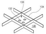
이때 본 발명에 따른 LED 백라이트어셈블리(120)는 특히 반사시트(130)에 별도의 광학적 구조물이 구비된 것에 특징을 두는바, 구체적으로는 반사시트(130) 상면으로부터 일정높이의 선형 격벽부재(134)가 종횡 교차됨으로써 일정형상의 격자구조(138)를 반복 제공하며, 복수개의 LED(124)는 수 개 단위로 구분되어 이들 각각의 격자구조(138) 내에 실장되는 형태를 취하고 있다.In this case, the
즉, 첨부된 도 4는 본 발명에 따른 반사시트(130)의 일부 확대도로서, 앞서 의 도 3과 함께 참조하면, LED(124)가 노출되는 반사시트(130) 상면으로부터는 불투명 반사재질로 이루어진 선형 리브(lib) 형상의 격벽부재(134)가 종횡 교차하여 사각의 격자구조를 반복 정의하고 있다.That is, FIG. 4 is an enlarged view of a part of the
이때 상기의 격벽부재(134)는 길이방향에 수직한 단면이 수 mm 정도, 바람직하게는 2 내지 5mm 의 높이를 나타내는 삼각형의 산 형상을 나타낼 수 있는데, 바람직하게는 이등변삼각형 형상을 나타낼 수 있고, 양 빗변과 반사시트(130) 표면 사이의 끼인각은 각각 10 내지 45°정도가 될 수 있다. 그리고 이 같은 격벽부재(134)는 반사시트(130)의 제조과정에서 이와 동일재질로 동일공정에서 구현되거나 또는 평면의 반사시트(130) 상에 별도 부착되는 형태도 가능한바, 상기 격벽부재(134)는 각각의 격자구조(138) 내에 실장되는 수 개의 LED(124)로부터 출사된 빛을 전면의 액정패널(110)을 향하도록 반사함으로써 해당 부분의 휘도를 향상시키는 역할을 한다.In this case, the
따라서 목적에 부합되도록 임의의 격자구조(138)를 정의하는 사방의 격벽부재(134)는 각각 내 외측의 두 겹 이상이 되도록 서로 나란한 복수개가 될 수 있다.Therefore, the four
또한 상기한 격벽부재(134)의 구체적인 형상, 예를 들어 길이방향에 수직한 단면형상 내지는 반사시트(130) 표면과의 사이에 끼인각 역시 목적에 따라 변형될 수 있는데, 첨부된 도 5는 격벽부재(134)의 또 다른 형태를 나타낸 확대 사시도로서, 이 경우 격벽부재(134)는 길이방향에 수직한 단면이 직사각형 형상을 나타내며, 이 외에 별도의 도면으로 제시하지는 않았지만 격벽부재(134)의 길이방향에 수 직한 단면 형상은 사다리꼴 내지는 기타 여러 가지 형태를 나타낼 수 있다.In addition, the specific shape of the
한편, 첨부된 도 6은 본 발명에 따른 액정표시장치모듈의 변형예를 나타낸 분해사시도로서, 앞서 도 3의 경우와 동일한 역할을 하는 부분에 대해서는 동일한 도면부호를 부여하여 중복된 설명을 생략한다.Meanwhile, FIG. 6 is an exploded perspective view showing a modified example of the liquid crystal display module according to the present invention, and the same reference numerals are assigned to parts which play the same role as the case of FIG.
이에 따른 차이점으로서 반사시트(130) 상면으로부터 노출되는 LED(124)와 광학시트(148) 사이로는 각각으로부터 일정거리를 유지하는 투명윈도우(140)가 개재되어 있고, LED(124)를 바라보는 투명윈도우(140) 배면으로는 반사도트(142)가 부착되어 있는 것을 특징으로 한다.As a result of the difference, a
이때 반사도트(142)의 역할은 LED(124)에서 출사된 직선광을 반사 및 확산시킴으로써 보다 균일한 면광원을 구현함과 동시에 색섞임을 가중시키는 것으로, 반사시트(130)와 유사하게 백색 또는 은색의 시트물로 제조될 수 있고, 도면에 나타낸 것처럼 반사시트(130)의 각 격자구조(138) 내에 실장되는 수 개의 LED(124)와 일대일 대응되는 원형을 나타내거나 또는 각각의 격자구조(138)와 일대일 대응되는 소정형상을 나타내는 것도 가능하다. 그리고 투명윈도우(140)는 상기의 반사도트(142)가 LED(124)와 일정거리를 유지하도록 지지하는 역할을 한다.At this time, the role of the reflecting
그리고 이 외에 부분은 앞서 도 3을 참조한 내용이 동일하게 적용될 수 있고, 특히 반사시트(130)에는 다수의 LED(124)가 일대일 삽입되는 다수의 관통홀(132)이 투공되어 LED(124)를 제외한 인쇄회로기판(122) 내지는 커버버툼(160) 내면을 덮어 가리고, 이러한 반사시트(130)의 상면으로부터는 일정높이의 선형 격벽 부재(134)가 종횡 교차됨으로써 일정형상의 격자구조(138)를 반복 제공하며, 복수개의 LED(124)는 수 개 단위로 구분되어 각각의 격자구조(138) 내에 실장되는 구조를 나타낸다.In addition to the above, other portions may be equally applied to the contents described with reference to FIG. 3, and in particular, the
그리고 이들 격벽부재(134)의 구체적인 내용 역시 앞서와 마찬가지이다.And the details of these
이상의 설명에서, 반사시트(130) 상면에서 종횡 교차되는 격벽부재(134)에 의해 정의되는 격자구조(138) 내에는 수 개의 LED(124)가 실장된다 하였는데, 이들 수 개의 LED(124)는 각 격자구조(138) 별로 백색광을 구현할 수 있고, 이를 만족시키는 여러 가지 실시예가 가능하다.In the above description,
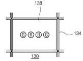
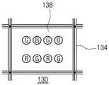
먼저 생각해 볼 수 있는 한 가지 방식은 격자구조(138) 내에 RGB LED(124)가 적어도 하나씩 실장되어 이들의 색섞임에 의한 백색광을 구현하는 경우로서, 이때의 RGB LED(124)는 일정한 단위조합을 이룰 수 있으며, 편의상 각각의 컬러를 나타내는 약자로만 표기하면 RGB, GRBG, RGGB, GRBGR 등이 가능하고, 이들 단위조합은 각각의 격자구조(138) 내에서 일렬 일회배열, 일렬 다회배열, 다열 일회배열, 다열 다회배열 방식으로 배치될 수 있다.One method that can be considered first is a case where at least one
아울러 이들 각각의 경우에 RGB LED(124)의 단위조합은 일직선상에 배치되거나 RGB LED(124)가 각각 삼각형의 꼭지점을 이루는 삼각배치 형태, GRBG 또는 RGGB LED(124)가 각각 사각형의 꼭지점을 이루는 사각배치 형태, GRBGR LED(124)가 각각 중심의 하나와 이를 두르는 사각형의 꼭지점을 이루는 오방배치 형태 등이 가능한바, 이들을 만족시키는 예는 무수히 많다 할 것이다.In each of these cases, the unit combination of the
또한 이와는 달리 격자구조(138) 내에 백색광을 발하는 적어도 하나의 W LED(124)가 실장되는 경우도 가능하며, 이의 배치방법은 목적에 따라 얼마든지 자유로울 수 있음은 쉽게 예상할 수 있다.Alternatively, at least one
또는 앞서의 두 가지 경우가 혼합된 예로서, 각각의 격자구조(138) 내에 적절한 수량의 RGB LED(124)와 W LED(124)가 소정 형태로 배열되는 것도 가능함은 물론이다.Alternatively, as an example of the above two cases being mixed, it is also possible to arrange an appropriate number of
그 결과 이하에서 살펴볼 도 7a 내지 도 7i는 몇 가지 예시에 지나지 않으며, 편의상 격자구조(138) 내에 RGB LED(124)가 적어도 하나씩 포함된 단위조합이 실장되는 경우만을 나타내었는바, 도 7a는 일직선상에 배치된 GRBG LED(124)가 격자구조(138) 내에서 일회, 일렬로 배열된 경우이고, 도 7b와 도 7c는 각각 GRBG LED(124)의 사각배치가 회전각도를 달리하여 격자구조(138) 내에서 일회, 일렬로 배열된 경우이며, 도 7d는 GRBGR LED(124)의 오방배치가 격자구조(138) 내에서 일회, 일렬로 배열된 경우이다.As a result, FIG. 7A to FIG. 7I, which will be described below, are merely examples. For convenience, only the case where the unit combination including at least one of the
또한 도 7e는 일직선상에 배치된 GRBGR LED(124)가 격자구조(138) 내에서 일회 배열된 경우이고, 도 7f는 RGB LED(124)의 삼각배치가 격자구조(138) 내에서 일회 배열된 경우이며, 도 7g는 일직선상에 배치된 GRBG LED(124)가 격자구조(138) 내에서 2회, 일렬로 배열된 경우이다.In addition, FIG. 7E illustrates a case where the
그리고 도 7h는 GRBG LED(124)의 사각배치가 격자구조(138) 내에서 2회 일렬로 배열된 경우이며, 마지막의 도 7i는 도 7h와 유사하지만 RGBG LED(124)의 사각배치가 격자구조(138) 내에서 각도를 달리하여 2회 일렬로 배열된 경우이다.7H illustrates a case in which the quadrangles of the
이상에서 살펴본 본 발명은 일반적인 LED 백라이트어셈블리의 문제점을 해소하는 장점을 보이는바, 반사시트 상에 반사재질로 이루어진 격벽부재를 부여하여 전체적인 휘도 상승과 더불어 격자구조 사이에서 나타나는 부분적인 휘도저하 현상을 해소하고 있다.The present invention as described above shows the advantages of solving the problems of the general LED backlight assembly, by providing a partition member made of a reflective material on the reflective sheet to solve the partial luminance degradation phenomenon between the lattice structure and the overall luminance increase. Doing.
아울러 각각의 격자구조 내에 백색광을 구현할 수 있는 LED의 여러 가지 배치예를 제공함으로써 고품위의 풍부한 백색광을 액정패널에 공급할 수 있으며, 아울러 각각의 격자구조는 독립된 별개의 발광영역으로 작용되는바, 분할구동에 유리한 효과를 나타낸다.In addition, by providing various arrangement examples of LEDs that can realize white light in each lattice structure, it is possible to supply a high-quality rich white light to the liquid crystal panel, and each lattice structure acts as a separate and separate light emitting area. It has an advantageous effect.
Claims (14)
Translated fromKoreanPriority Applications (3)
| Application Number | Priority Date | Filing Date | Title |
|---|---|---|---|
| KR1020050131721AKR101220204B1 (en) | 2005-12-28 | 2005-12-28 | Light Emitting Diodes back-light assembly and liquid crystal display device module using thereof |
| JP2006206278AJP4516549B2 (en) | 2005-12-28 | 2006-07-28 | Backlight assembly and liquid crystal display module using the same |
| US11/509,650US7530711B2 (en) | 2005-12-28 | 2006-08-25 | Backlight assembly and liquid crystal display module using the same |
Applications Claiming Priority (1)
| Application Number | Priority Date | Filing Date | Title |
|---|---|---|---|
| KR1020050131721AKR101220204B1 (en) | 2005-12-28 | 2005-12-28 | Light Emitting Diodes back-light assembly and liquid crystal display device module using thereof |
Publications (2)
| Publication Number | Publication Date |
|---|---|
| KR20070069499A KR20070069499A (en) | 2007-07-03 |
| KR101220204B1true KR101220204B1 (en) | 2013-01-09 |
Family
ID=37893609
Family Applications (1)
| Application Number | Title | Priority Date | Filing Date |
|---|---|---|---|
| KR1020050131721AActiveKR101220204B1 (en) | 2005-12-28 | 2005-12-28 | Light Emitting Diodes back-light assembly and liquid crystal display device module using thereof |
Country Status (3)
| Country | Link |
|---|---|
| US (1) | US7530711B2 (en) |
| JP (1) | JP4516549B2 (en) |
| KR (1) | KR101220204B1 (en) |
Families Citing this family (112)
| Publication number | Priority date | Publication date | Assignee | Title |
|---|---|---|---|---|
| KR101167301B1 (en)* | 2004-10-30 | 2012-07-19 | 엘지디스플레이 주식회사 | Back light unit of liquid crystal display device |
| KR20060124831A (en) | 2005-05-26 | 2006-12-06 | 엘지이노텍 주식회사 | Back light assembly and liquid crystal display device having same |
| KR100653070B1 (en)* | 2005-09-05 | 2006-12-01 | 삼성전자주식회사 | LCD Display |
| KR101237788B1 (en)* | 2005-12-29 | 2013-02-28 | 엘지디스플레이 주식회사 | LED light emitting unit and LED backlight assembly and liquid crystal display module |
| KR20070079649A (en)* | 2006-02-03 | 2007-08-08 | 삼성전자주식회사 | Backlight Assembly and Display Device Having Same |
| KR100790698B1 (en)* | 2006-04-19 | 2008-01-02 | 삼성전기주식회사 | Backlight Unit for Liquid Crystal Display |
| TW200815860A (en)* | 2006-09-18 | 2008-04-01 | Au Optronics Corp | Backlight module |
| US8226261B2 (en)* | 2006-09-20 | 2012-07-24 | Sharp Kabushiki Kaisha | Illumination device, backlight device used for liquid crystal display apparatus and liquid crystal display apparatus |
| US20090086491A1 (en) | 2007-09-28 | 2009-04-02 | Ruud Lighting, Inc. | Aerodynamic LED Floodlight Fixture |
| US9222632B2 (en) | 2013-01-31 | 2015-12-29 | Cree, Inc. | LED lighting fixture |
| US7686469B2 (en) | 2006-09-30 | 2010-03-30 | Ruud Lighting, Inc. | LED lighting fixture |
| US9028087B2 (en) | 2006-09-30 | 2015-05-12 | Cree, Inc. | LED light fixture |
| US9212812B2 (en) | 2013-02-11 | 2015-12-15 | Cree, Inc. | LED light fixture with integrated light shielding |
| CN101169548A (en)* | 2006-10-27 | 2008-04-30 | 鸿富锦精密工业(深圳)有限公司 | Backlight module |
| US7534010B2 (en)* | 2006-12-28 | 2009-05-19 | Chunghwa Picture Tubes, Ltd. | Backlight module |
| KR100851146B1 (en)* | 2007-02-05 | 2008-08-08 | 엘지이노텍 주식회사 | Surface light source device and display device using same |
| US8651685B2 (en)* | 2007-03-16 | 2014-02-18 | Cree, Inc. | Apparatus and methods for backlight unit with vertical interior reflectors |
| US8092042B2 (en)* | 2007-05-03 | 2012-01-10 | Ruud Lighting, Inc. | Shield member in LED apparatus |
| CN102289104B (en)* | 2007-05-23 | 2013-04-10 | 友达光电股份有限公司 | Backlight module |
| KR101363673B1 (en)* | 2007-06-14 | 2014-02-17 | 엘지디스플레이 주식회사 | Backlight unit and liquid crystal display device having the same |
| US7905618B2 (en)* | 2007-07-19 | 2011-03-15 | Samsung Led Co., Ltd. | Backlight unit |
| KR100951274B1 (en)* | 2007-07-19 | 2010-05-06 | 삼성엘이디 주식회사 | Backlight unit |
| WO2009018433A1 (en)* | 2007-07-31 | 2009-02-05 | Lsi Industries Inc. | Lighting apparatus |
| JP4997015B2 (en)* | 2007-07-31 | 2012-08-08 | エルジー ディスプレイ カンパニー リミテッド | Liquid crystal display backlight |
| TWI348059B (en)* | 2007-08-01 | 2011-09-01 | Au Optronics Corp | Backlight module |
| CN101688647A (en)* | 2007-08-08 | 2010-03-31 | 夏普株式会社 | Illuminating device and liquid crystal display |
| KR101408300B1 (en)* | 2007-11-02 | 2014-06-18 | 엘지디스플레이 주식회사 | LED backlight unit and liquid crystal display module using the same |
| JP4968014B2 (en)* | 2007-11-22 | 2012-07-04 | ソニー株式会社 | Backlight device and liquid crystal display device |
| DE102007059132A1 (en)* | 2007-12-07 | 2009-06-10 | Osram Gesellschaft mit beschränkter Haftung | Light unit and lamp |
| KR101445734B1 (en) | 2007-12-07 | 2014-10-01 | 삼성전자 주식회사 | Liquid Crystal Display |
| JP2009198017A (en)* | 2008-02-19 | 2009-09-03 | Sanyo Electric Co Ltd | Showcase |
| KR100918873B1 (en)* | 2008-02-20 | 2009-09-28 | 희성전자 주식회사 | Direct lighting type backlight unit using led lamps |
| US20100259470A1 (en)* | 2008-03-07 | 2010-10-14 | Yukihide Kohtoku | Light-emitting element, illumination device, and liquid crystal display device |
| JP5113573B2 (en)* | 2008-03-24 | 2013-01-09 | パナソニック株式会社 | LED lighting device |
| US7637630B2 (en)* | 2008-04-22 | 2009-12-29 | Ruud Lighting, Inc. | Integrated shield-gasket member in LED apparatus |
| TWI364557B (en)* | 2008-05-02 | 2012-05-21 | Chimei Innolux Corp | Light source and backlight module and liquid crystal display device using same |
| KR101460273B1 (en)* | 2008-05-19 | 2014-11-13 | 주식회사 아모센스 | Lighting device using light emitting diodes |
| KR101442006B1 (en)* | 2008-06-05 | 2014-09-19 | 삼성디스플레이 주식회사 | Backlight assembly and display device having same |
| KR100959660B1 (en)* | 2008-06-09 | 2010-05-26 | 주식회사 루멘스 | Surface light emitting device |
| JP5208597B2 (en)* | 2008-07-01 | 2013-06-12 | 富士フイルム株式会社 | Illumination device, imaging device |
| KR101471945B1 (en) | 2008-10-01 | 2014-12-12 | 삼성디스플레이 주식회사 | Backlight assembly |
| JP2012506119A (en)* | 2008-10-16 | 2012-03-08 | コーニンクレッカ フィリップス エレクトロニクス エヌ ヴィ | Lighting device configured to mix light from a first light emitting device and a second light emitting device |
| KR101545939B1 (en)* | 2008-10-27 | 2015-08-21 | 삼성디스플레이 주식회사 | Light source module, method of manufacturing same, and backlight assembly having same |
| JP5229736B2 (en)* | 2009-02-19 | 2013-07-03 | 株式会社ジャパンディスプレイイースト | Liquid crystal display |
| JP5236521B2 (en) | 2009-02-19 | 2013-07-17 | 株式会社ジャパンディスプレイイースト | Liquid crystal display |
| JP5035272B2 (en)* | 2009-03-03 | 2012-09-26 | ウシオ電機株式会社 | Light irradiation device |
| TW201037813A (en)* | 2009-04-08 | 2010-10-16 | Aussmak Optoelectronic Corp | Light emitting apparatus |
| JP4613254B2 (en)* | 2009-05-20 | 2011-01-12 | シャープ株式会社 | Light source device and display device including the same |
| KR101352276B1 (en)* | 2009-07-24 | 2014-01-16 | 엘지디스플레이 주식회사 | Apparatus for radiating heat of light emitting diode and liquid crystal display using the same |
| US8109647B2 (en) | 2009-07-28 | 2012-02-07 | Lg Innotek Co., Ltd. | Lighting device |
| KR101055053B1 (en) | 2009-07-28 | 2011-08-05 | 엘지이노텍 주식회사 | Lighting device |
| KR101628228B1 (en)* | 2009-09-10 | 2016-06-09 | 삼성디스플레이 주식회사 | Backlight assembly and display device comprising the same |
| JP2011090977A (en)* | 2009-10-26 | 2011-05-06 | Sharp Corp | Backlight unit and display device equipped therewith |
| KR20110125518A (en)* | 2010-05-13 | 2011-11-21 | 삼성전자주식회사 | Back light assembly and display device having same |
| US10037947B1 (en)* | 2010-06-29 | 2018-07-31 | Cooledge Lighting Inc. | Electronic devices with yielding substrates |
| US10883702B2 (en) | 2010-08-31 | 2021-01-05 | Ideal Industries Lighting Llc | Troffer-style fixture |
| US9116387B2 (en)* | 2010-08-31 | 2015-08-25 | Sharp Kabushiki Kaisha | Lighting device, display device and television device |
| CN103189680B (en)* | 2010-11-30 | 2015-04-15 | 夏普株式会社 | Lighting device, display device and television receiving device |
| US9581312B2 (en) | 2010-12-06 | 2017-02-28 | Cree, Inc. | LED light fixtures having elongated prismatic lenses |
| US9494293B2 (en) | 2010-12-06 | 2016-11-15 | Cree, Inc. | Troffer-style optical assembly |
| USD661833S1 (en)* | 2011-01-25 | 2012-06-12 | Panasonic Liquid Crystal Display Co., Ltd. | Reflective sheet for LCD backlights |
| JP5449274B2 (en)* | 2011-03-25 | 2014-03-19 | シャープ株式会社 | Lighting device and display device |
| EP2734779B1 (en)* | 2011-07-18 | 2016-09-14 | OSRAM GmbH | Lighting device and associated method |
| US10823347B2 (en) | 2011-07-24 | 2020-11-03 | Ideal Industries Lighting Llc | Modular indirect suspended/ceiling mount fixture |
| KR101357583B1 (en)* | 2011-07-29 | 2014-02-05 | 엘지이노텍 주식회사 | Lamp device within resin layer for light-guide and LCD using the same |
| US9423117B2 (en) | 2011-12-30 | 2016-08-23 | Cree, Inc. | LED fixture with heat pipe |
| US10544925B2 (en) | 2012-01-06 | 2020-01-28 | Ideal Industries Lighting Llc | Mounting system for retrofit light installation into existing light fixtures |
| US9777897B2 (en) | 2012-02-07 | 2017-10-03 | Cree, Inc. | Multiple panel troffer-style fixture |
| US9310038B2 (en) | 2012-03-23 | 2016-04-12 | Cree, Inc. | LED fixture with integrated driver circuitry |
| US9494294B2 (en) | 2012-03-23 | 2016-11-15 | Cree, Inc. | Modular indirect troffer |
| US9360185B2 (en) | 2012-04-09 | 2016-06-07 | Cree, Inc. | Variable beam angle directional lighting fixture assembly |
| US9874322B2 (en) | 2012-04-10 | 2018-01-23 | Cree, Inc. | Lensed troffer-style light fixture |
| US9285099B2 (en) | 2012-04-23 | 2016-03-15 | Cree, Inc. | Parabolic troffer-style light fixture |
| US9494823B2 (en)* | 2012-07-12 | 2016-11-15 | Samsung Display Co., Ltd. | Method and apparatus for achieving uniform high locality light |
| WO2014014134A1 (en)* | 2012-07-17 | 2014-01-23 | 엘지전자 주식회사 | Display device |
| KR20140048728A (en) | 2012-10-16 | 2014-04-24 | 삼성디스플레이 주식회사 | Optical sheet and backlight assembly having the same |
| US9435519B2 (en) | 2013-01-31 | 2016-09-06 | Cree, Inc. | Light-fixture support assembly |
| US10648643B2 (en) | 2013-03-14 | 2020-05-12 | Ideal Industries Lighting Llc | Door frame troffer |
| US9052075B2 (en)* | 2013-03-15 | 2015-06-09 | Cree, Inc. | Standardized troffer fixture |
| US20140286005A1 (en)* | 2013-03-20 | 2014-09-25 | Independence Led Lighting, Llc | Lighting Device Having Optimized Placement of Light-Emitting Elements for Parabolic Fixtures |
| JP6264171B2 (en)* | 2013-05-08 | 2018-01-24 | 日亜化学工業株式会社 | LED signal light |
| USD786471S1 (en) | 2013-09-06 | 2017-05-09 | Cree, Inc. | Troffer-style light fixture |
| US10451253B2 (en) | 2014-02-02 | 2019-10-22 | Ideal Industries Lighting Llc | Troffer-style fixture with LED strips |
| USD772465S1 (en) | 2014-02-02 | 2016-11-22 | Cree Hong Kong Limited | Troffer-style fixture |
| USD807556S1 (en) | 2014-02-02 | 2018-01-09 | Cree Hong Kong Limited | Troffer-style fixture |
| USD749768S1 (en) | 2014-02-06 | 2016-02-16 | Cree, Inc. | Troffer-style light fixture with sensors |
| US10527225B2 (en) | 2014-03-25 | 2020-01-07 | Ideal Industries, Llc | Frame and lens upgrade kits for lighting fixtures |
| US20160004123A1 (en)* | 2014-07-02 | 2016-01-07 | Kabushiki Kaisha Toshiba | Image display apparatus |
| CN104696828A (en)* | 2015-03-24 | 2015-06-10 | 深圳市华星光电技术有限公司 | Backlight module and liquid crystal display with backlight module |
| KR102330105B1 (en) | 2015-03-24 | 2021-11-25 | 삼성전자주식회사 | Display device |
| US9857521B2 (en) | 2015-04-20 | 2018-01-02 | Apple Inc. | Liquid crystal display with backlight color compensation structures |
| US10012354B2 (en) | 2015-06-26 | 2018-07-03 | Cree, Inc. | Adjustable retrofit LED troffer |
| US9671084B2 (en)* | 2015-07-23 | 2017-06-06 | Kuroi Electric Co., Ltd. | Display device |
| JP6688956B2 (en)* | 2015-09-01 | 2020-04-28 | パナソニックIpマネジメント株式会社 | Video display |
| KR102380466B1 (en)* | 2015-10-28 | 2022-03-31 | 엘지디스플레이 주식회사 | Backlight Unit with Partition Wall Member and Display Device having the same |
| US20170227816A1 (en)* | 2016-02-10 | 2017-08-10 | Glo Ab | Led backlight unit with separately and independently dimmable zones for a liquid crystal display |
| JP6631318B2 (en)* | 2016-02-29 | 2020-01-15 | 日亜化学工業株式会社 | Light emitting device and surface light emitting device using light emitting device |
| JP6628140B2 (en)* | 2016-03-03 | 2020-01-08 | パナソニックIpマネジメント株式会社 | Lighting equipment |
| US11079093B2 (en)* | 2016-10-07 | 2021-08-03 | Saturn Licensing Llc | Light emitting device, display device, and lighting device |
| JP6906968B2 (en)* | 2017-01-31 | 2021-07-21 | 株式会社ジャパンディスプレイ | Lighting device |
| US10274783B2 (en) | 2017-05-05 | 2019-04-30 | Pelka & Associates, Inc. | Direct-view LED backlight with gradient reflective layer |
| CN107092139B (en) | 2017-07-04 | 2020-06-02 | 京东方科技集团股份有限公司 | Backlight module, display module, control method of display module and storage medium |
| JP7033512B2 (en)* | 2018-08-08 | 2022-03-10 | シャープ株式会社 | Lighting equipment, display equipment, and television receivers |
| US20200133067A1 (en)* | 2018-10-24 | 2020-04-30 | GM Global Technology Operations LLC | Display system with geometric back light module |
| KR102195738B1 (en)* | 2019-07-12 | 2020-12-28 | 주식회사 제이앤비 | Method for fabricating direct light type backlight for module |
| CN110610929B (en)* | 2019-08-16 | 2021-12-03 | 武汉华星光电技术有限公司 | Backlight module |
| JP7221411B2 (en)* | 2019-10-02 | 2023-02-13 | 三菱電機株式会社 | Planar light source device and liquid crystal display device |
| KR102764406B1 (en)* | 2019-12-30 | 2025-02-07 | 엘지디스플레이 주식회사 | Back light unit and diplay including the same |
| KR102786031B1 (en)* | 2020-05-14 | 2025-03-27 | 삼성디스플레이 주식회사 | Light source plate, manufacturing method for the same and display device including the same |
| CN214041938U (en)* | 2020-11-04 | 2021-08-24 | 中强光电股份有限公司 | Light source module and display device |
| KR102853066B1 (en)* | 2021-12-13 | 2025-09-02 | 엘지디스플레이 주식회사 | Backlight unit and display device including the same |
| CN114475422A (en)* | 2021-12-23 | 2022-05-13 | 宁波福尔达智能科技股份有限公司 | Dynamic display atmosphere lamp and vehicle |
Citations (4)
| Publication number | Priority date | Publication date | Assignee | Title |
|---|---|---|---|---|
| KR20020047534A (en)* | 2000-12-13 | 2002-06-22 | 구본준, 론 위라하디락사 | Backlight unit in Liquid crystal display |
| US20040218390A1 (en)* | 2003-01-24 | 2004-11-04 | Digital Optics International Corporation | High-density illumination system |
| US20040233665A1 (en)* | 2003-05-21 | 2004-11-25 | West Robert S. | Devices for creating brightness profiles |
| WO2005015646A1 (en)* | 2003-08-07 | 2005-02-17 | Matsushita Electric Industrial Co., Ltd. | Led illumination light source |
Family Cites Families (12)
| Publication number | Priority date | Publication date | Assignee | Title |
|---|---|---|---|---|
| JPH0510369Y2 (en)* | 1989-09-05 | 1993-03-15 | ||
| AU2002359708A1 (en)* | 2001-12-14 | 2003-07-15 | Digital Optics International Corporation | Uniform illumination system |
| DE10245933B4 (en)* | 2002-09-30 | 2013-10-10 | Osram Opto Semiconductors Gmbh | Device for generating a bundled luminous flux |
| TWI288277B (en)* | 2004-02-20 | 2007-10-11 | Jr-Yung Liou | Flat light source with high brightness and high uniformity |
| KR101002311B1 (en) | 2004-03-19 | 2010-12-21 | 엘지디스플레이 주식회사 | Backlight Unit of LCD |
| JP2005321693A (en)* | 2004-05-11 | 2005-11-17 | Hitachi Displays Ltd | Liquid crystal display |
| KR100586970B1 (en)* | 2004-05-28 | 2006-06-08 | 삼성전기주식회사 | Backlight unit of liquid crystal display |
| JP4535792B2 (en)* | 2004-07-01 | 2010-09-01 | Nec液晶テクノロジー株式会社 | Backlight and liquid crystal display device including the backlight |
| TWI274209B (en)* | 2004-07-16 | 2007-02-21 | Chi Lin Technology Co Ltd | Light emitting diode and backlight module having light emitting diode |
| JP4543813B2 (en)* | 2004-08-04 | 2010-09-15 | ソニー株式会社 | Backlight device and liquid crystal display device including the backlight device |
| KR101035918B1 (en)* | 2004-12-08 | 2011-05-23 | 엘지디스플레이 주식회사 | Direct backlight |
| KR101187204B1 (en)* | 2005-06-08 | 2012-10-02 | 삼성디스플레이 주식회사 | Backlight assembly for simplifying assembling and display device provided with the same, and the assembling method of the backlight assembly |
- 2005
- 2005-12-28KRKR1020050131721Apatent/KR101220204B1/enactiveActive
- 2006
- 2006-07-28JPJP2006206278Apatent/JP4516549B2/enactiveActive
- 2006-08-25USUS11/509,650patent/US7530711B2/enactiveActive
Patent Citations (4)
| Publication number | Priority date | Publication date | Assignee | Title |
|---|---|---|---|---|
| KR20020047534A (en)* | 2000-12-13 | 2002-06-22 | 구본준, 론 위라하디락사 | Backlight unit in Liquid crystal display |
| US20040218390A1 (en)* | 2003-01-24 | 2004-11-04 | Digital Optics International Corporation | High-density illumination system |
| US20040233665A1 (en)* | 2003-05-21 | 2004-11-25 | West Robert S. | Devices for creating brightness profiles |
| WO2005015646A1 (en)* | 2003-08-07 | 2005-02-17 | Matsushita Electric Industrial Co., Ltd. | Led illumination light source |
Also Published As
| Publication number | Publication date |
|---|---|
| US7530711B2 (en) | 2009-05-12 |
| KR20070069499A (en) | 2007-07-03 |
| JP2007180005A (en) | 2007-07-12 |
| US20070070625A1 (en) | 2007-03-29 |
| JP4516549B2 (en) | 2010-08-04 |
Similar Documents
| Publication | Publication Date | Title |
|---|---|---|
| KR101220204B1 (en) | Light Emitting Diodes back-light assembly and liquid crystal display device module using thereof | |
| KR101237788B1 (en) | LED light emitting unit and LED backlight assembly and liquid crystal display module | |
| KR101134301B1 (en) | Light Emitting Diodes back-light assembly and liquid crystal display device module using thereof | |
| US9939680B2 (en) | Light diffusion plate and display apparatus having the same | |
| JP5324068B2 (en) | Backlight assembly and display device having the same | |
| KR101647490B1 (en) | Curved liquid Crystal Display device | |
| KR101299130B1 (en) | Liquid crystal display device | |
| KR20100109785A (en) | Liquid crystal display device | |
| KR101183447B1 (en) | reflector of back light for liquid crystal display device, back light assembly and liquid crystal display module using thereof | |
| US20090115931A1 (en) | Backlight unit and liquid crystal dispaly module including the same | |
| KR20090128693A (en) | Liquid crystal display device | |
| KR20120065752A (en) | Liquid crystal display device | |
| KR101591336B1 (en) | Liquid crystal display | |
| KR101823013B1 (en) | Liquid crystal display device | |
| KR20120065753A (en) | Liquid crystal display device | |
| KR101236892B1 (en) | Liquid crystal display device module having function not-loosen screw | |
| KR20110029752A (en) | LCD Display | |
| KR102093629B1 (en) | Liquid crystal display device | |
| KR101221391B1 (en) | Light Emitting Diodes back-light assembly and liquid crystal display device module using thereof | |
| KR20060095144A (en) | LED backlight assembly and liquid crystal display module using the same | |
| KR20120074921A (en) | Liquid crystal display device | |
| KR101537561B1 (en) | Backlight unit and liquid crystal display module including the same | |
| KR101408300B1 (en) | LED backlight unit and liquid crystal display module using the same | |
| KR20180073743A (en) | Liquid crystal display device and multi-surface display device including the same | |
| KR102007830B1 (en) | Backlight unit and liquid crystal display device including the same |
Legal Events
| Date | Code | Title | Description |
|---|---|---|---|
| PA0109 | Patent application | Patent event code:PA01091R01D Comment text:Patent Application Patent event date:20051228 | |
| PG1501 | Laying open of application | ||
| A201 | Request for examination | ||
| PA0201 | Request for examination | Patent event code:PA02012R01D Patent event date:20101221 Comment text:Request for Examination of Application Patent event code:PA02011R01I Patent event date:20051228 Comment text:Patent Application | |
| PE0902 | Notice of grounds for rejection | Comment text:Notification of reason for refusal Patent event date:20120619 Patent event code:PE09021S01D | |
| E701 | Decision to grant or registration of patent right | ||
| PE0701 | Decision of registration | Patent event code:PE07011S01D Comment text:Decision to Grant Registration Patent event date:20121224 | |
| GRNT | Written decision to grant | ||
| PR0701 | Registration of establishment | Comment text:Registration of Establishment Patent event date:20130103 Patent event code:PR07011E01D | |
| PR1002 | Payment of registration fee | Payment date:20130104 End annual number:3 Start annual number:1 | |
| PG1601 | Publication of registration | ||
| FPAY | Annual fee payment | Payment date:20151228 Year of fee payment:4 | |
| PR1001 | Payment of annual fee | Payment date:20151228 Start annual number:4 End annual number:4 | |
| FPAY | Annual fee payment | Payment date:20161214 Year of fee payment:5 | |
| PR1001 | Payment of annual fee | Payment date:20161214 Start annual number:5 End annual number:5 | |
| FPAY | Annual fee payment | Payment date:20171218 Year of fee payment:6 | |
| PR1001 | Payment of annual fee | Payment date:20171218 Start annual number:6 End annual number:6 | |
| FPAY | Annual fee payment | Payment date:20181226 Year of fee payment:7 | |
| PR1001 | Payment of annual fee | Payment date:20181226 Start annual number:7 End annual number:7 | |
| FPAY | Annual fee payment | Payment date:20191212 Year of fee payment:8 | |
| PR1001 | Payment of annual fee | Payment date:20191212 Start annual number:8 End annual number:8 | |
| PR1001 | Payment of annual fee | Payment date:20201222 Start annual number:9 End annual number:9 | |
| PR1001 | Payment of annual fee | Payment date:20211216 Start annual number:10 End annual number:10 | |
| PR1001 | Payment of annual fee | Payment date:20241216 Start annual number:13 End annual number:13 |