KR101219309B1 - signal processing device and image processing device - Google Patents
signal processing device and image processing deviceDownload PDFInfo
- Publication number
- KR101219309B1 KR101219309B1KR1020100094212AKR20100094212AKR101219309B1KR 101219309 B1KR101219309 B1KR 101219309B1KR 1020100094212 AKR1020100094212 AKR 1020100094212AKR 20100094212 AKR20100094212 AKR 20100094212AKR 101219309 B1KR101219309 B1KR 101219309B1
- Authority
- KR
- South Korea
- Prior art keywords
- matrix
- dct
- slant
- haar
- matrix operation
- Prior art date
- Legal status (The legal status is an assumption and is not a legal conclusion. Google has not performed a legal analysis and makes no representation as to the accuracy of the status listed.)
- Expired - Fee Related
Links
Images


Classifications
- G—PHYSICS
- G06—COMPUTING OR CALCULATING; COUNTING
- G06F—ELECTRIC DIGITAL DATA PROCESSING
- G06F17/00—Digital computing or data processing equipment or methods, specially adapted for specific functions
- G06F17/10—Complex mathematical operations
- G06F17/14—Fourier, Walsh or analogous domain transformations, e.g. Laplace, Hilbert, Karhunen-Loeve, transforms
- G06F17/145—Square transforms, e.g. Hadamard, Walsh, Haar, Hough, Slant transforms
- G—PHYSICS
- G06—COMPUTING OR CALCULATING; COUNTING
- G06F—ELECTRIC DIGITAL DATA PROCESSING
- G06F17/00—Digital computing or data processing equipment or methods, specially adapted for specific functions
- G06F17/10—Complex mathematical operations
- G06F17/14—Fourier, Walsh or analogous domain transformations, e.g. Laplace, Hilbert, Karhunen-Loeve, transforms
- G06F17/147—Discrete orthonormal transforms, e.g. discrete cosine transform, discrete sine transform, and variations therefrom, e.g. modified discrete cosine transform, integer transforms approximating the discrete cosine transform
Landscapes
- Physics & Mathematics (AREA)
- Engineering & Computer Science (AREA)
- General Physics & Mathematics (AREA)
- Mathematical Physics (AREA)
- Theoretical Computer Science (AREA)
- Computational Mathematics (AREA)
- Mathematical Analysis (AREA)
- Mathematical Optimization (AREA)
- Pure & Applied Mathematics (AREA)
- Data Mining & Analysis (AREA)
- Algebra (AREA)
- Software Systems (AREA)
- General Engineering & Computer Science (AREA)
- Databases & Information Systems (AREA)
- Discrete Mathematics (AREA)
- Complex Calculations (AREA)
- Compression Or Coding Systems Of Tv Signals (AREA)
Abstract
Translated fromKoreanDescription
Translated fromKorean본 발명은 신호 처리 소자 및 이미지 처리 소자에 관한 것으로, 더욱 상세하게는, DCT(Discrete Cosine Transformation)-II, Haar, Slant 변환을 수행하는 신호 처리 소자 및 이미지 처리 소자에 관한 것이다.The present invention relates to a signal processing device and an image processing device, and more particularly, to a signal processing device and an image processing device for performing Discrete Cosine Transformation (DCT) -II, Haar, and Slant transformation.
DCT(Discrete Cosine Transformation)-II, Haar, 및 Slant 변환 기술은 신호 처리 분야에서 다양하게 적용되고 있다. 특히, 이와 같은 신호 변환 기술은 이미지 인코딩 처리나 신호의 모듈레이션 등을 위해 사용되고 있다.Discrete Cosine Transformation (DCT) -II, Haar, and Slant transformation techniques have been widely applied in the field of signal processing. In particular, such signal conversion techniques are used for image encoding processing, signal modulation, and the like.
DCT, 특히 DCT-II는 신호처리 및 영상처리에 사용된다. 특히 DCT는 신호의 에너지 성분 대부분이 저주파 성분 일부에 집중되는 '에너지 집중 현상'을 가지고 있기 때문에, 손실 압축에 널리 사용한다. 예를 들어, JPEG 영상 압축, MJPEG, MPEG, 디브이 동영상 압축등에서 DCT를 사용한다. N × N 블록에 2차원 DCT-II을 적용하고, 결과값을 양자화하고 엔트로피 부호화한다.DCT, in particular DCT-II, is used for signal processing and image processing. In particular, DCT is widely used for lossy compression because it has an 'energy concentration phenomenon' where most of the energy components of the signal are concentrated in some of the low frequency components. For example, DCT is used in JPEG image compression, MJPEG, MPEG, DVD movie compression, and the like. Two-dimensional DCT-II is applied to the N × N block, and the result is quantized and entropy encoded.
또한, Haar 변환 및 Slant 변환도 다양한 신호처리 분야에 사용된다.In addition, Haar transform and Slant transform are also used in various signal processing fields.
이와 같은, DCT-II, Haar 변환, 및 Slant 변환을 위한 회로는 각각 별도의 회로 또는 별도의 칩으로 구현된다. 하지만, 이와 같은 변환 회로들이 별개로 구현될 경우, 이 회로들을 포함하는 장치는 부피가 커질 뿐만 아니라 처리 속도도 느려지게 된다.As such, the circuits for DCT-II, Haar conversion, and Slant conversion are each implemented as separate circuits or separate chips. However, when such conversion circuits are implemented separately, the device including these circuits becomes bulky and slow in processing speed.
이에 따라, DCT-II, Haar 변환, 및 Slant 변환을 수행하는 통합 회로를 구현하기 위한 방안의 모색이 요청된다.Accordingly, there is a need for a scheme for implementing an integrated circuit that performs DCT-II, Haar transformation, and Slant transformation.
본 발명은 상기와 같은 문제점을 해결하기 위하여 안출된 것으로서, 본 발명의 목적은, 입력된 신호에 대해, DCT 행렬 연산, Haar 행렬 연산, 및 Slant 행렬 연산 중 스위치부에 의해 선택된 행렬 연산을 수행하는 행렬 연산부를 포함하는 신호 처리 소자 및 이를 적용한 이미지 처리 소자를 제공함에 있다.SUMMARY OF THE INVENTION The present invention has been made to solve the above problems, and an object of the present invention is to perform a matrix operation selected by a switch unit among a DCT matrix operation, a Haar matrix operation, and a Slant matrix operation on an input signal. The present invention provides a signal processing device including a matrix operation unit and an image processing device using the same.
상기 목적을 달성하기 위한 본 발명의 일 실시예에 따른, 신호 처리 소자는, DCT 행렬 연산, Haar 행렬 연산, 및 Slant 행렬 연산 중 어느 하나를 선택하는 스위치부; 및 입력된 신호에 대해, DCT 행렬 연산, Haar 행렬 연산, 및 Slant 행렬 연산 중 상기 스위치부에 의해 선택된 행렬 연산을 수행하는 행렬 연산부;를 포함한다.According to an embodiment of the present invention, a signal processing device includes: a switch unit which selects one of a DCT matrix operation, a Haar matrix operation, and a Slant matrix operation; And a matrix operator configured to perform a matrix operation selected by the switch unit among the DCT matrix operation, the Haar matrix operation, and the Slant matrix operation on the input signal.
그리고, 상기 행렬 연산부는, 상기 DCT(Discrete Cosine Transformation)-II 행렬 연산, Haar 행렬 연산, 및 Slant 행렬 연산에 공유되어 이용되는 하나의 버터플라이 구조를 포함할 수도 있다.The matrix operator may include one butterfly structure that is shared and used for the Discrete Cosine Transformation (DCT) -II matrix operation, the Haar matrix operation, and the Slant matrix operation.
또한, 상기 행렬 연산부는, 입력된 신호에 대해 행 퍼뮤테이션(permutation) 행렬 연산을 수행하고, 연산이 완료된 신호를 스위치부로 전송하는 행 퍼뮤테이션 행렬 연산부; 상기 스위치부에서 출력되는 신호에 대해 DCT-II 행렬 연산을 수행하는 DCT-II 행렬 연산부; 상기 스위치부에서 출력되는 신호에 대해 Haar 행렬 연산을 수행하는 Haar 행렬 연산부; 상기 스위치부에서 출력되는 신호에 대해 Slant 행렬 연산을 수행하는 Slant 행렬 연산부; 상기 DCT-II 행렬 연산부, Haar 행렬 연산부, 및 Slant 행렬 연산부 중 어느 하나에서 출력되는 신호에 대해 버터플라이 구조 연산을 수행하는 버터플라이 구조 연산부; 및 상기 버터플라이 구조 연산부에서 출력되는 신호에 대해 열 퍼뮤테이션 행렬 연산을 수행하는 열 퍼뮤테이션 행렬 연산부;를 포함할 수도 있다.The matrix operation unit may further include: a row permutation matrix operation unit configured to perform a row permutation matrix operation on the input signal, and transmit the completed signal to the switch unit; A DCT-II matrix operation unit performing a DCT-II matrix operation on the signal output from the switch unit; A Haar matrix operation unit performing a Haar matrix operation on the signal output from the switch unit; A slant matrix calculator configured to perform a slant matrix operation on the signal output from the switch unit; A butterfly structure operation unit performing a butterfly structure operation on a signal output from any one of the DCT-II matrix operation unit, the Haar matrix operation unit, and the Slant matrix operation unit; And a column permutation matrix operator configured to perform a column permutation matrix operation on the signal output from the butterfly structure calculator.
그리고, 상기 스위치부는, 상기 행 퍼뮤테이션 행렬 연산부로부터 입력된 신호를 상기 DCT-II 행렬 연산부, Haar 행렬 연산부, 및 Slant 행렬 연산부 중 어느 하나로 출력할 수도 있다.The switch unit may output a signal input from the row permutation matrix operator to any one of the DCT-II matrix operator, the Haar matrix operator, and the Slant matrix operator.
또한, 상기 DCT-II 행렬 연산부는, 아래의 수식에 포함된 행렬 [C]N에 대한 행렬 연산을 수행할 수도 있다.In addition, the DCT-II matrix operator may perform a matrix operation on the matrix [C]N included in the following equation.

여기에서,


그리고, 상기 Haar 행렬 연산부는, 아래의 수식에 포함된 행렬 HT(N)에 대한 행렬 연산을 수행할 수도 있다.The Haar matrix operator may perform a matrix operation on the matrix HT (N) included in the following equation.

또한, 상기 Slant 행렬 연산부는, 아래의 수식에 포함된 행렬 S(N)에 대한 행렬 연산을 수행할 수도 있다.In addition, the Slant matrix operator may perform a matrix operation on the matrix S (N) included in the following equation.

그리고, 상기 행렬 연산부는, DCT-II 행렬 연산, Haar 행렬 연산, 및 Slant 행렬 연산을 선택적으로 수행하는 하이브리드 구조를 포함할 수도 있다.The matrix operator may include a hybrid structure for selectively performing a DCT-II matrix operation, a Haar matrix operation, and a Slant matrix operation.
또한, 상기 스위치부, 행렬 연산부는 하나의 칩으로 구현될 수도 있다.In addition, the switch unit and the matrix operator may be implemented as one chip.
한편, 본 발명의 일 실시예에 따른, 이미지 처리 소자는, 상술된 신호 처리 소자를 이용하여 이미지 신호에 대한 인코딩을 수행한다.Meanwhile, the image processing device according to an embodiment of the present invention performs encoding on the image signal by using the signal processing device described above.
본 발명의 다양한 실시예에 따르면, 입력된 신호에 대해, DCT 행렬 연산, Haar 행렬 연산, 및 Slant 행렬 연산 중 스위치부에 의해 선택된 행렬 연산을 수행하는 행렬 연산부를 포함하는 신호 처리 소자 및 이를 적용한 이미지 처리 소자를 제공할 수 있게 되어, 신호 처리 소자는 하나의 칩으로 DCT-II, Haar 변환, 및 Slant 변환을 선택적으로 수행할 수 있는 하이브리드 구조로 구현될 수 있게 된다.According to various embodiments of the present disclosure, a signal processing device including a matrix operation unit for performing a matrix operation selected by a switch unit among DCT matrix operations, Haar matrix operations, and Slant matrix operations on an input signal and an image using the same By providing a processing element, the signal processing element may be implemented in a hybrid structure capable of selectively performing DCT-II, Haar transformation, and Slant transformation with one chip.
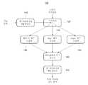
도 1은 본 발명의 일 실시예에 따른, DCT-II, Haar 변환, 및 Slant 변환이 모두 가능한 하이브리드 구조의 신호처리소자의 구성을 도시한 블럭도,
도 2는 본 발명의 일 실시예에 따른, 8x8의 DCT-II 행렬에 대한 버터플라이 데이터 흐름 다이어그램을 도시한 도면,
도 3은 본 발명의 일 실시예에 따른, 8x8의 Haar 행렬에 대한 버터플라이 데이터 흐름 다이어그램을 도시한 도면,
도 4는 본 발명의 일 실시예에 따른, 8x8의 Slant 행렬에 대한 버터플라이 데이터 흐름 다이어그램을 도시한 도면이다.1 is a block diagram illustrating a configuration of a signal processing device of a hybrid structure capable of all of DCT-II, Haar conversion, and Slant conversion, according to an embodiment of the present invention;
2 is a butterfly data flow diagram for an 8x8 DCT-II matrix, in accordance with an embodiment of the invention;
3 illustrates a butterfly data flow diagram for an 8x8 Haar matrix, in accordance with an embodiment of the invention.
4 illustrates a butterfly data flow diagram for an 8 × 8 Slant matrix, in accordance with an embodiment of the present invention.
이하에서는 도면을 참조하여 본 발명을 보다 상세하게 설명한다.Hereinafter, with reference to the drawings will be described the present invention in more detail.
먼저, DCT-II, Haar 변환, 및 Slant 변환 연산을 위한 행렬들을 블럭-인버스 처리(block-inverse processing)에 기초하여 분해하여 새로운 형태로 표현하기 위한 수식 전개 과정을 설명한다. 이와 같은 수식 전개 과정을 통해, DCT-II, Haar 변환, 및 Slant 변환을 위한 행렬은 유사한 리커시브 계산 패턴을 가지게 되며, 하나의 직교 특성 행렬(othogonal character matrix) 및 특정 희소 행렬(special sparse matrix)로 분해된다. 그리고, 특정 희소 행렬은 자켓 행렬(Jacket matrix)을 포함한다. 이와 같이, DCT-II, Haar 변환, 및 Slant 변환을 위한 행렬들은 분해 과정을 통해 서로 공유되는 부분을 발견할 수 있으며, 이와 같이 공유되는 부분을 버터플라이 구조를 이용하여 구현할 수 있게 된다. 이를 통해, DCT-II, Haar 변환, 및 Slant 변환을 하나의 회로 구조에서 선택적으로 처리할 수 있는 하이브리드 구조의 신호 처리 소자를 구현할 수 있게 된다. 이와 같은, 하이브리드 구조의 신호 처리 소자의 구현을 위한 행렬 분해 과정을 이하에서 수식 전개를 통해 설명한다.
First, a process of developing an equation for decomposing and expressing matrices for DCT-II, Haar transform, and Slant transform operations in a new form based on block-inverse processing is described. Through this equation expansion process, the matrices for DCT-II, Haar transform, and Slant transform have similar recursive computational patterns, one orthogonal character matrix, and a special sparse matrix. Decompose to And, the particular sparse matrix includes a jacket matrix. As such, the matrices for the DCT-II, the Haar transform, and the Slant transform can find a part shared with each other through a decomposition process, and the shared part can be implemented using a butterfly structure. Through this, it is possible to implement a signal processing device of a hybrid structure that can selectively process DCT-II, Haar transformation, and Slant transformation in one circuit structure. The matrix decomposition process for the implementation of the signal processing device of the hybrid structure will be described below by developing the equation.
1. 자켓 행렬의 개념 및 성질1. Concept and Properties of Jacket Matrix
일반적인 행렬(예를 들어, 실수 대칭, Hermitian, unitary 행렬 등)은 unitary 변환에 의해 대각화될 수 있다. 일반적인 경우, 선형 독립의 열을 포함하는 행렬은 AE=QR로 팩터화(factorization)될 수 있다. 이와 같은 팩터화는 자켓 행렬을 통해 DCT/Haar/Slant 변환과 같은 직교 행렬에 적용될 수 있다. 여기에서, R은 희소 행렬(sparse matrix)이고 Q는 unitary 행렬을 나타낸다. QR 분해의 특수 케이스로, 행렬 Q는 trigonometric 변환 행렬로 고정될 수도 있다.General matrices (eg real symmetry, Hermitian, unitary matrices, etc.) can be diagonalized by unitary transformation. In a general case, a matrix containing linearly independent columns may be factorized with AE = QR. This factorization can be applied to orthogonal matrices such as the DCT / Haar / Slant transform through the jacket matrix. Where R is a sparse matrix and Q is a unitary matrix. As a special case of QR decomposition, the matrix Q may be fixed with a trigonometric transformation matrix.
자켓 행렬은 c의 가중치를 가진 일반적인 Hadamard 행렬을 포함한다. 여기에서, c는 j(j는 허수 단위(imaginary unit :

일반적인 정의에 의하면, 정방 행렬

Hadamard, DFT, DCT, Haar, 및 Slant 행렬과 같은 직교 행렬은 자켓 행렬군을 포함한다. NxN 자켓 행렬은 리커시브(recursive) 형태의 아래의 공식을 이용하여 구할 수 있다.Orthogonal matrices, such as Hadamard, DFT, DCT, Haar, and Slant matrices, include jacket matrix groups. The N × N jacket matrix can be obtained using the following formula in a recursive form.


여기에서,
From here,
2. DCT/HAAR/SLANT 행렬의 분해2. Decomposition of DCT / HAAR / SLANT Matrix
A. 자켓 행렬을 통한 DCT 행렬의 리커시브 팩터화A. Recursive Factorization of DCT Matrix through Jacket Matrix
DCT-II 행렬 [CN]의 각 요소는 다음과 같이 정의된다.Each element of the DCT-II matrix [CN ] is defined as follows.


여기에서,
From here,
상기의 공식을 이용하여, 2x2 의 DCT-II 행렬은 다음과 같이 간단히 구할 수 있다.Using the above formula, a 2 × 2 DCT-II matrix can be simply obtained as follows.

여기에서,


4x4의 DCT-II 행렬은 다음과 같은 형태를 가진다.The 4x4 DCT-II matrix has the following form.

여기에, 행 퍼뮤테이션(permutation) 행렬인 [Pr]4를 곱하면, 다음과 같이 표현된다.Multiplied by [Pr]4 which is a row permutation matrix, it is expressed as follows.

여기에서, 행 퍼뮤테이션 행렬은 다음과 같이 정의된다.Here, the row permutation matrix is defined as follows.
[Pr]2 = [I]2,[Pr]2 = [I]2 ,


또한, 코사인의 성질에 의해

4x4의 열 퍼뮤테이션 행렬은 다음과 같이 정의된다.The 4x4 column permutation matrix is defined as

수식 (7)에 상기 열 퍼뮤테이션 행렬을 곱하면, 다음과 같이 정리된다.Multiplying the column permutation matrix by Equation (7) gives the following arrangement.


여기에서,

그러면, 수식 (8)은 다음과 같이 정리될 수 있다.Then, equation (8) can be summarized as follows.

이 때,

즉, 수식 (10)은 블럭 역행렬에 해당되는 자켓 행렬 타입의 희소 행렬(sparse matrix)임을 나타내고 있다.That is, Equation (10) indicates that the matrix is a sparse matrix of the jacket matrix type corresponding to the block inverse matrix.
따라서, 일반적인 DCT-II 행렬 [C]N은 다음과 같은 리커시브(recursive) 형태로 표현될 수 있음을 확인할 수 있다.Therefore, it can be seen that the general DCT-II matrix [C]N can be expressed in the following recursive form.

여기에서,


여기에서,

그리고, 이에 대한 역행렬을 구해보면 다음과 같다.In addition, the inverse matrix for this is as follows.

수식 (14)의 왼쪽 위에 있는 [C]N의 블럭 행렬인 [C]N/2은 리커시브 팩터화(recursive factorization)된 것을 확인할 수 있다. 하지만, 오른쪽 아래에 있는 [B]N/2는 리커시브 팩터화(recursive factorization)되어 있지 않다.A block matrix [C]N at the upper left of the
본 실시예에 따른 알고리즘에서, [B]N/2는 수식 (12)와 삼각함수 공식을 이용하여 리커시브 형태 및 관계에 대해 아래와 같이 설명된다. 수식 (12)에 따르면, NxN의 행렬인 [B]N은 아래의 삼각함수 공식과 수식 (14)에 의해 다음과 같이 정의된다.In the algorithm according to the present embodiment, [B]N / 2 is described below with respect to the recursive shape and relationship using Equation (12) and a trigonometric formula. According to equation (12), [B]N which is a matrix of NxN is defined as follows by the following trigonometric formula and equation (14).


여기에서,
상기 삼각함수 공식을 이용하면, [B]N은 다음과 같이 정리된다.Using the trigonometric formula, [B]N is summarized as follows.

여기에서,

From here,
8x8의 DCT-II 행렬은 다음과 같이 정리된다.The 8x8 DCT-II matrix is arranged as follows.

그리고, 이는 다음과 같이 표현될 수도 있다.And this may be expressed as follows.


모든 퍼뮤테이션 행렬을 제외시키면, 수식 (16)은 다음과 같이 정리된다.Excluding all permutation matrices, equation (16) is summarized as follows.

이상 설명한 바와 같이, DCT-II 행렬은 정리되게 된다.
As described above, the DCT-II matrix is arranged.
B. 자켓 행렬을 통한 Haar 행렬의 리커시브 팩터화B. Recursive Factorization of Haar Matrix Through Jacket Matrix
Haar 행렬 HT(N)은 다음과 같은 Haar 함수 {har(r,m,t)}의 세트로 구해진다.The Haar matrix HT (N) is obtained by the following set of Haar functions {har (r, m, t)}.
har (0,0,t) = 1,

예를 들어, 2x2의 Haar 행렬은 다음과 같이 구할 수 있다.For example, a 2x2 Haar matrix can be obtained as follows.


여기에서,
또한, 8x8의 Haar 행렬은 다음과 같이 구할 수 있다.In addition, an 8x8 Haar matrix can be obtained as follows.

HT(8) 행렬을 행 및 열 퍼뮤테이션 행렬이 곱해진 Har(N) 행렬 형태로 정리하면 다음과 같다.The HT (8) matrix is arranged in the form of a Har (N) matrix multiplied by a row and column permutation matrix.


여기에서,

수식 (20)을 분해하면 다음과 같다.The equation (20) is decomposed as follows.

여기에서,

여기에서,
그리고, 수식 (21)의 역행렬은 블럭 역행렬임을 다음과 같이 확인할 수 있다.And, it can be confirmed that the inverse of Equation (21) is a block inverse as follows.

일반적으로, 다음과 같이 HT(N)을 구할 수 있다.In general, HT (N) can be obtained as follows.

그리고, 이에 대한 역행렬은,And the inverse of this is

이와 같이, Haar 행렬은 분해되어 리커시브 팩터화된 형태로 표현될 수 있다.
As such, the Haar matrix can be decomposed and represented in a recursive factorized form.
C. 자켓 행렬을 통한 Haar 행렬의 리커시브 팩터화C. Recursive factorization of Haar matrices through jacket matrices
S(N)을 NxN Slant 행렬로 정의하면, 가장 낮은 차수의 Slant 행렬은 다음과 같이 정의된다.If S (N) is defined as an N × N Slant matrix, the lowest order Slant matrix is defined as follows.

그리고, N=4인 경우는 다음과 같이 정의된다.The case where N = 4 is defined as follows.

여기에서,
수식 (27)에 행 퍼뮤테이션 행렬


여기에서,
따라서, 수식 (27)을 다시 정리하면 다음과 같다.Therefore, the equation (27) is rearranged as follows.

여기에서, 희소 행렬인

이와 같은 방식으로, 낮은 차수의 Slant 행렬과 희소 행렬을 이용하여 높은 차수의 Slant 행렬을 유도할 수 있으며, 이와같은 과정을 통해 N차의 Slant 행렬을 구하면 다음과 같다.In this way, a high order Slant matrix can be derived using a low order Slant matrix and a sparse matrix. The Nth order Slant matrix is obtained as follows.

여기에서,


From here,
예를 들어, 8x8의 Slant 행렬은 다음과 같이 정리된다.For example, an 8x8 Slant matrix is arranged as follows.

아래의 행 퍼뮤테이션 행렬 및 열 퍼뮤테이션 행렬을 곱하면 다음과 같이 정리된다.Multiplying the row permutation matrix and column permutation matrix below gives the following:


이 때,

여기에서, 희소 행렬에 해당되는

여기에서,
양쪽의 퍼뮤테이션 행렬을 제거하면, S(8)은 다음과 같이 표현된다.Removing both permutation matrices, S (8) is expressed as

그리고, 이에 대한 역행렬을 구해보면,And, if you get the inverse of this,

여기에서,
상기 식에서 리커시브의 기본 요소는 S(N)으로부터 유도될 수 있다.In the above formula, the basic element of the recursive can be derived from S (N).
일반적인 식을 구해보면, 다음과 같다.The general equation is:

그리고, 이에 대한 역행렬은 다음과 같다.And the inverse of this is as follows.

여기에서,
이와 같이, Slant 행렬 S(N)은 분해되어 리커시브 팩터화된 형태로 표현될 수 있게 된다.
As such, the Slant matrix S (N) is decomposed and can be expressed in a recursive factorized form.
이상에서 살펴본 바와 같이, DCT-II 행렬인 [C]N, Haar 행렬인 HT(N), 및 Slant 행렬인 S(N)은 수식 (11), (24), 및 (35)에서 살펴본 바와 같이, 모두
따라서, 이와 같이 분해된 DCT-II 행렬, Haar 행렬, 및 Slant 행렬의 수식을 이용하여 회로를 설계할 경우, DCT-II, Haar 변환, 및 Slant 변환이 모두 가능한 하이브리드 구조의 회로를 설계할 수 있게 된다.Therefore, when designing a circuit using the equations of the decomposed DCT-II matrix, Haar matrix, and Slant matrix, it is possible to design a hybrid structure circuit capable of DCT-II, Haar transformation, and Slant transformation. do.
또한, 이와 같은 수식 (11), (24), 및 (35)에 의해 DCT-II, Haar 변환, 및 Slant 변환을 수행할 경우, 그 계산에 대한 복잡도는 아래의 표와 같다.In addition, when DCT-II, Haar transform, and Slant transform are performed by the above formulas (11), (24), and (35), the complexity of the calculation is shown in the table below.

3.3.하이브리드hybrid 구조를 포함하는 신호 처리 소자의 구조 Structure of a signal processing element comprising a structure
이하에서는, 도 1을 참고하여, 하이브리드 구조를 포함하는 신호처리소자(100)에 대해 설명한다. 도 1은 본 발명의 일 실시예에 따른, DCT-II, Haar 변환, 및 Slant 변환이 모두 가능한 하이브리드 구조의 신호처리소자(100)의 구성을 도시한 블럭도이다.Hereinafter, the
도 1에 도시된 바와 같이, 행 퍼뮤테이션 행렬 연산부(110), 스위치부(120), DCT-II(Discrete Cosine Transformation - II) 행렬 연산부(130), Haar 행렬 연산부(140), Slant 행렬 연산부(150), 버터플라이 구조 연산부(160), 및 열 퍼뮤테이션 행렬 연산부(170)를 포함한다.As shown in FIG. 1, the row permutation
여기에서, 행 퍼뮤테이션 행렬 연산부(110), DCT-II(Discrete Cosine Transformation - II) 행렬 연산부(130), Haar 행렬 연산부(140), Slant 행렬 연산부(150), 버터플라이 구조 연산부(160), 및 열 퍼뮤테이션 행렬 연산부(170)는 행렬 연산부를 구성한다. 즉 행렬 연산부는 입력된 신호에 대해, DCT 행렬 연산, Haar 행렬 연산, 및 Slant 행렬 연산 중 스위치부(120)에 의해 선택된 행렬 연산을 수행한다. 이 때, 행렬 연산부는, DCT(Discrete Cosine Transformation)-II 행렬 연산, Haar 행렬 연산, 및 Slant 행렬 연산에 공유되어 이용되는 하나의 버터플라이 구조를 포함하게 된다. 이하에서는 행렬 연산부의 세부 구조에 대해 도 1을 참고하여 설명한다.Here, the row permutation
행 퍼뮤테이션 행렬 연산부(110)는 입력된 신호에 대해 행 퍼뮤테이션(permutation) 행렬 연산을 수행하고, 연산이 완료된 신호를 스위치부(120)로 전송한다. 즉, 행 퍼뮤테이션 행렬 연산부(110)는 상술된 수식들에서 [Pr]N 행렬에 대한 연산을 수행한다.The row
스위치부(120)는 DCT 행렬 연산, Haar 행렬 연산, 및 Slant 행렬 연산 중 어느 하나를 선택하여 신호를 출력한다. 즉, 스위치부(120)는 DCT 행렬 연산부(130), Haar 행렬 연산부(140), 및 Slant 행렬 연산부(150) 중 어느 하나와 연결되게 된다.The
스위치부(120)는 외부에서 입력되는 스위치 제어신호에 따라, DCT 행렬 연산부(130), Haar 행렬 연산부(140), 및 Slant 행렬 연산부(150) 중 연결할 유닛을 선택하게 된다. 이 때, 스위치 제어신호는 DCT 행렬 연산, Haar 행렬 연산, 및 Slant 행렬 연산 중 어느 하나를 선택하기 위한 제어신호이며, 이는 사용자에 의해 입력된 명령에 의해 결정될 수도 있다.The
이와 같이, 신호 처리 소자(100)는 스위치부(120)를 포함함으로써 DCT 행렬 연산, Haar 행렬 연산, 및 Slant 행렬 연산 중 어느 하나를 선택하여 처리할 수 있게 된다.As such, the
DCT-II 행렬 연산부(130)는 스위치부(120)에서 출력되는 신호에 대해 DCT-II 행렬 연산을 수행한다. 즉, DCT-II 행렬 연산부(130)는 아래의 수식에 포함된 행렬 [C]N에 대한 행렬 연산을 수행하게 된다. 아래의 수식은 상기 설명한 수식 (11)~(13)에 해당된다.The DCT-

여기에서,


여기에서,

이와 같이, DCT-II 행렬 연산부(130)는 상기 수식에 대응되는 회로를 포함하여, 상기 수식에 해당되는 신호처리를 수행하게 된다.As described above, the DCT-
Haar 행렬 연산부(140)는 스위치부에서 출력되는 신호에 대해 Haar 행렬 연산을 수행한다. 즉, Haar 행렬 연산부(140)는 아래의 수식에 포함된 행렬 HT(N)에 대한 행렬 연산을 수행한다.The

이와 같이, Haar 행렬 연산부(140)는 상기 수식에 대응되는 회로를 포함하여, 상기 수식에 해당되는 신호처리를 수행하게 된다.As described above, the
Slant 행렬 연산부(150)는 스위치부(120)에서 출력되는 신호에 대해 Slant 행렬 연산을 수행한다. 즉, Slant 행렬 연산부(150)는 아래의 수식에 포함된 행렬 S(N)에 대한 행렬 연산을 수행하게 된다.The

이와 같이, Slant 행렬 연산부(150)는 상기 수식에 대응되는 회로를 포함하여, 상기 수식에 해당되는 신호처리를 수행하게 된다.As described above, the
버터 플라이 구조 연산부(160)는 DCT-II 행렬 연산부(130), Haar 행렬 연산부(140), 및 Slant 행렬 연산부(150) 중 어느 하나에서 출력되는 신호에 대해 버터플라이 구조 연산을 수행한다. 버터 플라이 구조 연산부(160)는 DCT 행렬 연산, Haar 행렬 연산, 및 Slant 행렬 연산에 모두 공유되는 구조를 포함한다. 예를 들어, 버터플라이 구조 연산부(160)는 DCT 행렬 연산, Haar 행렬 연산, 및 Slant 행렬 연산에 모두 포함되는
열 퍼뮤테이션 행렬 연산부(170)는 버터플라이 구조 연산부(170)에서 출력되는 신호에 대해 열 퍼뮤테이션 행렬 연산을 수행한다. 즉, 열 퍼뮤테이션 행렬 연산부(170)는 상술된 수식들에서 [Pc]N 행렬에 대한 연산을 수행한다.The column
이와 같은 하이브리드 구조를 통해, 신호 처리 소자(100)는 공통된 버터플라이 구조를 이용하여 DCT-II 행렬, Haar 행렬, 및 Slant 행렬의 연산을 수행하게 된다. 따라서, 신호 처리 소자(100)는 입력된 신호에 대해 DCT-II, Haar 변환, 및 Slant 변환을 선택적으로 수행할 수 있게 된다.Through such a hybrid structure, the
또한, 이와 같은 구조의 신호 처리 소자를 하나의 칩으로 구현할 경우, DCT-II, Haar 변환, 및 Slant 변환을 선택적으로 수행할 수 있는 하나의 회로 칩을 구현할 수 있게 된다.In addition, when the signal processing element having such a structure is implemented as one chip, it is possible to implement a circuit chip capable of selectively performing DCT-II, Haar transformation, and Slant transformation.
이하에서는 도 2 내지 도 4를 참고하여, 8x8의 DCT-II 행렬, Haar 행렬, 및 Slant 행렬 각각에 대한 버터플라이 데이터 흐름 다이어그램을 설명한다.Hereinafter, a butterfly data flow diagram for each of the 8 × 8 DCT-II matrix, the Haar matrix, and the Slant matrix will be described with reference to FIGS. 2 to 4.
도 2는 본 발명의 일 실시예에 따른, 8x8의 DCT-II 행렬에 대한 버터플라이 데이터 흐름 다이어그램을 도시한 도면이다. 그리고, 도 3은 본 발명의 일 실시예에 따른, 8x8의 Haar 행렬에 대한 버터플라이 데이터 흐름 다이어그램을 도시한 도면이다. 도 4는 본 발명의 일 실시예에 따른, 8x8의 Slant 행렬에 대한 버터플라이 데이터 흐름 다이어그램을 도시한 도면이다.2 illustrates a butterfly data flow diagram for an 8x8 DCT-II matrix, in accordance with an embodiment of the invention. 3 illustrates a butterfly data flow diagram for an 8x8 Haar matrix, in accordance with an embodiment of the invention. 4 illustrates a butterfly data flow diagram for an 8 × 8 Slant matrix, in accordance with an embodiment of the present invention.
도 2 내지 도 4에서 도시된 바와 같이, 세가지 행렬에 대한 버터플라이 데이터 흐름 다이어그램에서, 행 퍼뮤테이션 행렬 연산부(110), 버터플라이 구조 연산부(160), 및 열 퍼뮤테이션 행렬 연산부(170)에 대응되는 부분은 서로 공통되는 것을 확인할 수 있다. 그리고, DCT-II 행렬 연산부(130), Haar 행렬 연산부(140), 및 Slant 행렬 연산부(150)에 대응되는 부분만이 서로 다른 것을 확인할 수 있다.As shown in FIGS. 2-4, in the butterfly data flow diagram for the three matrices, it corresponds to the row
따라서, 이와 같이 공통되는 부분은 하나만 포함하고, 서로 다른 부분인 DCT-II 행렬 연산부(130), Haar 행렬 연산부(140), 및 Slant 행렬 연산부(150)는 스위치부(120)를 이용하여 선택하도록 회로를 구현함으로써, DCT-II 행렬, Haar 행렬, 및 Slant 행렬의 연산을 선택적으로 수행할 수 있는 하이브리드 구조의 신호 처리 소자를 설계할 수 있게 된다.Thus, the common part includes only one common part, and the DCT-
또한, 이와 같은 신호 처리 소자(100)를 이용하여, DCT-II, Haar 변환, 및 Slant 변환을 선택적으로 수행함으로써 이미지 신호에 대한 인코딩을 수행하는 이미지 처리 소자를 제조할 수도 있게 된다.In addition, by using the
하지만, 본 실시예에 따른 신호 처리 소자는, 이미지 처리 소자 이외에도 DCT-II, Haar 변환, 및 Slant 변환이 적용되는 신호 처리 소자라면 어떤 것이라도 적용될 수 있음은 물론이다.However, the signal processing element according to the present embodiment may be applied to any signal processing element to which DCT-II, Haar transform, and Slant transform is applied in addition to the image processing element.
한편, 상술한 수식들에 의해 DCT-II, Haar 변환, 및 Slant 변환을 수행하는 과정에 대한 신호 처리 과정은 다양한 컴퓨터 수단을 통하여 수행될 수 있는 프로그램 명령 형태로 구현되어 컴퓨터로 판독 가능한 기록 매체에 기록될 수 있다. 이때, 컴퓨터로 판독 가능한 기록매체는 프로그램 명령, 데이터 파일, 데이터 구조 등을 단독으로 또는 조합하여 포함할 수 있다. 한편, 기록매체에 기록되는 프로그램 명령은 본 발명을 위하여 특별히 설계되고 구성된 것들이거나 컴퓨터 소프트웨어 당업자에게 공지되어 사용 가능한 것일 수도 있다.On the other hand, the signal processing for the process of performing the DCT-II, Haar transformation, and Slant transformation by the above-described formula is implemented in the form of program instructions that can be performed by various computer means to a computer-readable recording medium Can be recorded. In this case, the computer-readable recording medium may include program instructions, data files, data structures, and the like, alone or in combination. On the other hand, the program instructions recorded on the recording medium may be those specially designed and configured for the present invention or may be available to those skilled in the art of computer software.
컴퓨터로 판독 가능한 기록매체에는 하드 디스크, 플로피 디스크 및 자기 테이프와 같은 자기 매체(Magnetic Media), CD-ROM, DVD와 같은 광기록 매체(Optical Media), 플롭티컬 디스크(Floptical Disk)와 같은 자기-광 매체(Magneto-Optical Media), 및 롬(ROM), 램(RAM), 플래시 메모리 등과 같은 프로그램 명령을 저장하고 수행하도록 특별히 구성된 하드웨어 장치가 포함된다. 한편, 이러한 기록매체는 프로그램 명령, 데이터 구조 등을 지정하는 신호를 전송하는 반송파를 포함하는 광 또는 금속선, 도파관 등의 전송 매체일 수도 있다.The computer-readable recording medium includes a magnetic recording medium such as a magnetic medium such as a hard disk, a floppy disk and a magnetic tape, an optical medium such as a CD-ROM and a DVD, a magnetic disk such as a floppy disk, A magneto-optical media, and a hardware device specifically configured to store and execute program instructions such as ROM, RAM, flash memory, and the like. The recording medium may be a transmission medium such as an optical or metal wire, a waveguide, or the like including a carrier wave for transmitting a signal specifying a program command, a data structure, or the like.
또한, 프로그램 명령에는 컴파일러에 의해 만들어지는 것과 같은 기계어 코드뿐만 아니라 인터프리터 등을 사용해서 컴퓨터에 의해서 실행될 수 있는 고급 언어 코드를 포함한다. 상술한 하드웨어 장치는 본 발명의 동작을 수행하기 위해 하나 이상의 소프트웨어 모듈로서 작동하도록 구성될 수 있으며, 그 역도 마찬가지이다.In addition, program instructions include not only machine code generated by a compiler, but also high-level language code that can be executed by a computer using an interpreter or the like. The hardware devices described above may be configured to operate as one or more software modules to perform the operations of the present invention, and vice versa.
또한, 이상에서는 본 발명의 바람직한 실시예에 대하여 도시하고 설명하였지만, 본 발명은 상술한 특정의 실시예에 한정되지 아니하며, 청구범위에서 청구하는 본 발명의 요지를 벗어남이 없이 당해 발명이 속하는 기술분야에서 통상의 지식을 가진자에 의해 다양한 변형실시가 가능한 것은 물론이고, 이러한 변형실시들은 본 발명의 기술적 사상이나 전망으로부터 개별적으로 이해되어져서는 안될 것이다.While the present invention has been particularly shown and described with reference to exemplary embodiments thereof, it is to be understood that the invention is not limited to the disclosed exemplary embodiments, but, on the contrary, It will be understood by those skilled in the art that various changes in form and detail may be made therein without departing from the spirit and scope of the present invention.
100 : 신호 처리 소자110 ; 행 퍼뮤테이션 행렬 연산부
120 : 스위치부130 : DCT-II 행렬 연산부
140 : Haar 행렬 연산부150 : Slant 행렬 연산부
160 : 버터플라이 구조 연산부170 : 열 퍼뮤테이션 행렬 연산부100:
120: switch unit 130: DCT-II matrix calculation unit
140: Haar matrix calculator 150: Slant matrix calculator
160: butterfly structure calculation unit 170: column permutation matrix calculation unit
Claims (10)
Translated fromKorean입력된 신호에 대해, DCT-II 행렬 연산, Haar 행렬 연산, 및 Slant 행렬 연산 중 상기 스위치부에 의해 선택된 행렬 연산을 수행하는 행렬 연산부;를 포함하는 것을 특징으로 하는 신호 처리 소자.A switch unit for selecting one of a discrete cosine transform (DCT) -II matrix operation, a Haar matrix operation, and a Slant matrix operation; And
And a matrix arithmetic unit configured to perform a matrix arithmetic operation selected by the switch unit among DCT-II matrix arithmetic operation, Haar matrix arithmetic operation, and Slant matrix arithmetic operation on the input signal.
상기 행렬 연산부는,
DCT-II 행렬 연산, Haar 행렬 연산, 및 Slant 행렬 연산에 공유되어 이용되는 하나의 버터플라이 구조를 포함하는 것을 특징으로 하는 신호 처리 소자.The method of claim 1,
The matrix operation unit,
A signal processing element comprising one butterfly structure shared and used for DCT-II matrix operation, Haar matrix operation, and Slant matrix operation.
상기 행렬 연산부는,
입력된 신호에 대해 행 퍼뮤테이션(permutation) 행렬 연산을 수행하고, 연산이 완료된 신호를 스위치부로 전송하는 행 퍼뮤테이션 행렬 연산부;
상기 스위치부에서 출력되는 신호에 대해 DCT-II 행렬 연산을 수행하는 DCT-II 행렬 연산부;
상기 스위치부에서 출력되는 신호에 대해 Haar 행렬 연산을 수행하는 Haar 행렬 연산부;
상기 스위치부에서 출력되는 신호에 대해 Slant 행렬 연산을 수행하는 Slant 행렬 연산부;
상기 DCT-II 행렬 연산부, Haar 행렬 연산부, 및 Slant 행렬 연산부 중 어느 하나에서 출력되는 신호에 대해 버터플라이 구조 연산을 수행하는 버터플라이 구조 연산부; 및
상기 버터플라이 구조 연산부에서 출력되는 신호에 대해 열 퍼뮤테이션 행렬 연산을 수행하는 열 퍼뮤테이션 행렬 연산부;를 포함하는 것을 특징으로 하는 신호 처리 소자.The method of claim 1,
The matrix operation unit,
A row permutation matrix operator for performing a row permutation matrix operation on the input signal and transmitting the completed signal to the switch unit;
A DCT-II matrix operation unit performing a DCT-II matrix operation on the signal output from the switch unit;
A Haar matrix operation unit performing a Haar matrix operation on the signal output from the switch unit;
A slant matrix calculator configured to perform a slant matrix operation on the signal output from the switch unit;
A butterfly structure operation unit performing a butterfly structure operation on a signal output from any one of the DCT-II matrix operation unit, the Haar matrix operation unit, and the Slant matrix operation unit; And
And a column permutation matrix operator configured to perform a column permutation matrix operation on the signal output from the butterfly structure calculator.
상기 스위치부는,
상기 행 퍼뮤테이션 행렬 연산부로부터 입력된 신호를 상기 DCT-II 행렬 연산부, Haar 행렬 연산부, 및 Slant 행렬 연산부 중 어느 하나로 출력하는 것을 특징으로 하는 신호 처리 소자.The method of claim 3,
Wherein,
And a signal input from the row permutation matrix operator to one of the DCT-II matrix operator, the Haar matrix operator, and the Slant matrix operator.
상기 행렬 연산부는,
DCT-II 행렬 연산, Haar 행렬 연산, 및 Slant 행렬 연산을 선택적으로 수행하는 하이브리드 구조를 포함하는 것을 특징으로 하는 신호 처리 소자.The method of claim 1,
The matrix operation unit,
And a hybrid structure for selectively performing DCT-II matrix operation, Haar matrix operation, and Slant matrix operation.
상기 스위치부, 행렬 연산부는 하나의 칩으로 구현되는 것을 특징으로 하는 신호 처리 소자.The method of claim 1,
The switch unit and the matrix operation unit is a signal processing element, characterized in that implemented in one chip.
An image processing element for performing encoding on an image signal using the signal processing element according to any one of claims 1 to 4, 8 and 9.
Priority Applications (2)
| Application Number | Priority Date | Filing Date | Title |
|---|---|---|---|
| KR1020100094212AKR101219309B1 (en) | 2010-09-29 | 2010-09-29 | signal processing device and image processing device |
| US12/953,644US8706786B2 (en) | 2010-09-29 | 2010-11-24 | Signal processing device and image processing device |
Applications Claiming Priority (1)
| Application Number | Priority Date | Filing Date | Title |
|---|---|---|---|
| KR1020100094212AKR101219309B1 (en) | 2010-09-29 | 2010-09-29 | signal processing device and image processing device |
Publications (2)
| Publication Number | Publication Date |
|---|---|
| KR20120032727A KR20120032727A (en) | 2012-04-06 |
| KR101219309B1true KR101219309B1 (en) | 2013-01-08 |
Family
ID=45871742
Family Applications (1)
| Application Number | Title | Priority Date | Filing Date |
|---|---|---|---|
| KR1020100094212AExpired - Fee RelatedKR101219309B1 (en) | 2010-09-29 | 2010-09-29 | signal processing device and image processing device |
Country Status (2)
| Country | Link |
|---|---|
| US (1) | US8706786B2 (en) |
| KR (1) | KR101219309B1 (en) |
Families Citing this family (2)
| Publication number | Priority date | Publication date | Assignee | Title |
|---|---|---|---|---|
| US8930872B2 (en)* | 2012-02-17 | 2015-01-06 | Netronome Systems, Incorporated | Staggered island structure in an island-based network flow processor |
| US8902902B2 (en) | 2012-07-18 | 2014-12-02 | Netronome Systems, Incorporated | Recursive lookup with a hardware trie structure that has no sequential logic elements |
Citations (2)
| Publication number | Priority date | Publication date | Assignee | Title |
|---|---|---|---|---|
| US5748903A (en)* | 1995-07-21 | 1998-05-05 | Intel Corporation | Encoding images using decode rate control |
| KR20090027811A (en)* | 2007-09-13 | 2009-03-18 | 이문호 | Design Method of Hybrid DC / DFT / Wavelet High-Speed Structure for Transcoding Based on Jacket Matrix |
Family Cites Families (12)
| Publication number | Priority date | Publication date | Assignee | Title |
|---|---|---|---|---|
| EP0557204A3 (en)* | 1992-02-21 | 1995-10-18 | Sony Corp | Discrete cosine transform apparatus and inverse discrete cosine transform apparatus |
| US6006246A (en)* | 1992-11-13 | 1999-12-21 | Sony Corporation | Method of and apparatus for multiplying matrix data |
| US5408425A (en)* | 1993-05-25 | 1995-04-18 | The Aerospace Corporation | Split-radix discrete cosine transform |
| US5812788A (en)* | 1995-07-21 | 1998-09-22 | Intel Corporation | Encoding/decoding video signals using quantization tables based on explicitly encoded base and scale matrices |
| JP3274593B2 (en)* | 1995-09-27 | 2002-04-15 | 日本電気株式会社 | Conversion device and reversible conversion device capable of reversible conversion |
| US6011499A (en)* | 1996-06-27 | 2000-01-04 | Intel Corporation | Encoding/decoding video signals using multiple run-val mapping tables |
| US6058215A (en)* | 1997-04-30 | 2000-05-02 | Ricoh Company, Ltd. | Reversible DCT for lossless-lossy compression |
| US6788811B1 (en)* | 1999-05-10 | 2004-09-07 | Ricoh Company, Ltd. | Coding apparatus, decoding apparatus, coding method, decoding method, amd computer-readable recording medium for executing the methods |
| US7099909B2 (en)* | 2002-06-19 | 2006-08-29 | The Aerospace Corporation | Merge and split fast fourier block transform method |
| JP3928605B2 (en)* | 2003-08-06 | 2007-06-13 | ソニー株式会社 | Noise removal apparatus, noise removal method, and program |
| KR20110091000A (en)* | 2008-11-07 | 2011-08-10 | 미쓰비시덴키 가부시키가이샤 | Picture coding device and picture decoding device |
| KR101362696B1 (en)* | 2011-10-19 | 2014-02-17 | 전북대학교산학협력단 | Signal transformation apparatus applied hybrid architecture, signal transformation method, and recording medium |
- 2010
- 2010-09-29KRKR1020100094212Apatent/KR101219309B1/ennot_activeExpired - Fee Related
- 2010-11-24USUS12/953,644patent/US8706786B2/ennot_activeExpired - Fee Related
Patent Citations (2)
| Publication number | Priority date | Publication date | Assignee | Title |
|---|---|---|---|---|
| US5748903A (en)* | 1995-07-21 | 1998-05-05 | Intel Corporation | Encoding images using decode rate control |
| KR20090027811A (en)* | 2007-09-13 | 2009-03-18 | 이문호 | Design Method of Hybrid DC / DFT / Wavelet High-Speed Structure for Transcoding Based on Jacket Matrix |
Also Published As
| Publication number | Publication date |
|---|---|
| KR20120032727A (en) | 2012-04-06 |
| US20120078990A1 (en) | 2012-03-29 |
| US8706786B2 (en) | 2014-04-22 |
Similar Documents
| Publication | Publication Date | Title |
|---|---|---|
| Liang et al. | Fast multiplierless approximations of the DCT with the lifting scheme | |
| KR101362696B1 (en) | Signal transformation apparatus applied hybrid architecture, signal transformation method, and recording medium | |
| Bouguezel et al. | A fast 8× 8 transform for image compression | |
| Bouguezel et al. | A novel transform for image compression | |
| Sreema et al. | A low complex and scalable reconfigurable simulation for orthogonal approximation using dct | |
| Prattipati et al. | A fast 8× 8 integer Tchebichef transform and comparison with integer cosine transform for image compression | |
| Kekre et al. | A new multi-resolution hybrid wavelet for analysis and image compression | |
| KR101219309B1 (en) | signal processing device and image processing device | |
| Yoshida et al. | Two dimensional non-separable adaptive directional lifting structure of discrete wavelet transform | |
| Bouguezel et al. | A multiplication-free transform for image compression | |
| Brahimi et al. | An efficient fast integer DCT transform for images compression with 16 additions only | |
| Coelho et al. | Error‐free computation of 8‐point discrete cosine transform based on the Loeffler factorisation and algebraic integers | |
| Hasan et al. | Multilevel decomposition Discrete Wavelet Transform for hardware image compression architectures applications | |
| JP6555814B2 (en) | Orthogonal transformation processing device, inverse orthogonal transformation processing device, encoding device, decoding device, and computer program | |
| Kyochi et al. | General factorization of conjugate-symmetric Hadamard transforms | |
| KR101722215B1 (en) | Apparatus and method for discrete cosine transform | |
| KR20090027811A (en) | Design Method of Hybrid DC / DFT / Wavelet High-Speed Structure for Transcoding Based on Jacket Matrix | |
| Hatim et al. | Efficient architecture for direct 8× 8 2D DCT computations with earlier zigzag ordering | |
| Abdelrasoul et al. | Real‐time unified architecture for forward/inverse discrete cosine transform in high efficiency video coding | |
| Jdidia et al. | Hardware implementation of 1-D 8-point adaptive multiple transform in post-HEVC standard | |
| Zhang et al. | A High-Performance with Low-Resource Utility FPGA Implementation of Variable Size HEVC 2D-DCT Transform | |
| Mamatha et al. | Hybrid architecture for sinusoidal and non-sinusoidal transforms | |
| JP5325072B2 (en) | Matrix decomposition apparatus, matrix decomposition method and program | |
| Khatri et al. | Implementation of discrete Cosine transform using VLSI | |
| Bharath Kumar et al. | Efficient SBT Architecture for HEVC |
Legal Events
| Date | Code | Title | Description |
|---|---|---|---|
| A201 | Request for examination | ||
| PA0109 | Patent application | St.27 status event code:A-0-1-A10-A12-nap-PA0109 | |
| PA0201 | Request for examination | St.27 status event code:A-1-2-D10-D11-exm-PA0201 | |
| R18-X000 | Changes to party contact information recorded | St.27 status event code:A-3-3-R10-R18-oth-X000 | |
| D13-X000 | Search requested | St.27 status event code:A-1-2-D10-D13-srh-X000 | |
| D14-X000 | Search report completed | St.27 status event code:A-1-2-D10-D14-srh-X000 | |
| PG1501 | Laying open of application | St.27 status event code:A-1-1-Q10-Q12-nap-PG1501 | |
| E902 | Notification of reason for refusal | ||
| PE0902 | Notice of grounds for rejection | St.27 status event code:A-1-2-D10-D21-exm-PE0902 | |
| T11-X000 | Administrative time limit extension requested | St.27 status event code:U-3-3-T10-T11-oth-X000 | |
| T11-X000 | Administrative time limit extension requested | St.27 status event code:U-3-3-T10-T11-oth-X000 | |
| E13-X000 | Pre-grant limitation requested | St.27 status event code:A-2-3-E10-E13-lim-X000 | |
| P11-X000 | Amendment of application requested | St.27 status event code:A-2-2-P10-P11-nap-X000 | |
| P13-X000 | Application amended | St.27 status event code:A-2-2-P10-P13-nap-X000 | |
| R18-X000 | Changes to party contact information recorded | St.27 status event code:A-3-3-R10-R18-oth-X000 | |
| E701 | Decision to grant or registration of patent right | ||
| PE0701 | Decision of registration | St.27 status event code:A-1-2-D10-D22-exm-PE0701 | |
| GRNT | Written decision to grant | ||
| PR0701 | Registration of establishment | St.27 status event code:A-2-4-F10-F11-exm-PR0701 | |
| PR1002 | Payment of registration fee | St.27 status event code:A-2-2-U10-U11-oth-PR1002 Fee payment year number:1 | |
| PG1601 | Publication of registration | St.27 status event code:A-4-4-Q10-Q13-nap-PG1601 | |
| P22-X000 | Classification modified | St.27 status event code:A-4-4-P10-P22-nap-X000 | |
| FPAY | Annual fee payment | Payment date:20151230 Year of fee payment:4 | |
| PR1001 | Payment of annual fee | St.27 status event code:A-4-4-U10-U11-oth-PR1001 Fee payment year number:4 | |
| PN2301 | Change of applicant | St.27 status event code:A-5-5-R10-R13-asn-PN2301 St.27 status event code:A-5-5-R10-R11-asn-PN2301 | |
| FPAY | Annual fee payment | Payment date:20161229 Year of fee payment:5 | |
| PR1001 | Payment of annual fee | St.27 status event code:A-4-4-U10-U11-oth-PR1001 Fee payment year number:5 | |
| LAPS | Lapse due to unpaid annual fee | ||
| PC1903 | Unpaid annual fee | St.27 status event code:A-4-4-U10-U13-oth-PC1903 Not in force date:20180103 Payment event data comment text:Termination Category : DEFAULT_OF_REGISTRATION_FEE | |
| PC1903 | Unpaid annual fee | St.27 status event code:N-4-6-H10-H13-oth-PC1903 Ip right cessation event data comment text:Termination Category : DEFAULT_OF_REGISTRATION_FEE Not in force date:20180103 | |
| R18-X000 | Changes to party contact information recorded | St.27 status event code:A-5-5-R10-R18-oth-X000 | |
| PN2301 | Change of applicant | St.27 status event code:A-5-5-R10-R13-asn-PN2301 St.27 status event code:A-5-5-R10-R11-asn-PN2301 | |
| R18-X000 | Changes to party contact information recorded | St.27 status event code:A-5-5-R10-R18-oth-X000 | |
| PN2301 | Change of applicant | St.27 status event code:A-5-5-R10-R13-asn-PN2301 St.27 status event code:A-5-5-R10-R11-asn-PN2301 | |
| PN2301 | Change of applicant | St.27 status event code:A-5-5-R10-R13-asn-PN2301 St.27 status event code:A-5-5-R10-R11-asn-PN2301 | |
| R18-X000 | Changes to party contact information recorded | St.27 status event code:A-5-5-R10-R18-oth-X000 | |
| R18-X000 | Changes to party contact information recorded | St.27 status event code:A-5-5-R10-R18-oth-X000 |