KR101217516B1 - cluster tool - Google Patents
cluster toolDownload PDFInfo
- Publication number
- KR101217516B1 KR101217516B1KR1020060064673AKR20060064673AKR101217516B1KR 101217516 B1KR101217516 B1KR 101217516B1KR 1020060064673 AKR1020060064673 AKR 1020060064673AKR 20060064673 AKR20060064673 AKR 20060064673AKR 101217516 B1KR101217516 B1KR 101217516B1
- Authority
- KR
- South Korea
- Prior art keywords
- load lock
- opening
- lock chamber
- cluster tool
- pressure
- Prior art date
- Legal status (The legal status is an assumption and is not a legal conclusion. Google has not performed a legal analysis and makes no representation as to the accuracy of the status listed.)
- Active
Links
- 230000001105regulatory effectEffects0.000claimsabstractdescription29
- 238000004891communicationMethods0.000claimsabstractdescription21
- 238000000034methodMethods0.000claimsdescription40
- 238000013022ventingMethods0.000claimsdescription6
- 239000000758substrateSubstances0.000claimsdescription5
- 235000012431wafersNutrition0.000description41
- 238000012546transferMethods0.000description12
- 238000012986modificationMethods0.000description9
- 230000004048modificationEffects0.000description9
- 239000002184metalSubstances0.000description6
- 239000002245particleSubstances0.000description6
- 238000012545processingMethods0.000description3
- 230000002411adverseEffects0.000description2
- 238000005086pumpingMethods0.000description2
- 239000004065semiconductorSubstances0.000description2
- 238000004140cleaningMethods0.000description1
- 230000003749cleanlinessEffects0.000description1
- 239000000356contaminantSubstances0.000description1
- 238000000151depositionMethods0.000description1
- 238000005137deposition processMethods0.000description1
- 238000001035dryingMethods0.000description1
- 238000005530etchingMethods0.000description1
- 239000012530fluidSubstances0.000description1
- 230000001939inductive effectEffects0.000description1
- 239000000463materialSubstances0.000description1
- 238000000059patterningMethods0.000description1
- 230000000149penetrating effectEffects0.000description1
- 238000007789sealingMethods0.000description1
- 239000010409thin filmSubstances0.000description1
Images


Classifications
- H—ELECTRICITY
- H01—ELECTRIC ELEMENTS
- H01L—SEMICONDUCTOR DEVICES NOT COVERED BY CLASS H10
- H01L21/00—Processes or apparatus adapted for the manufacture or treatment of semiconductor or solid state devices or of parts thereof
- H01L21/67—Apparatus specially adapted for handling semiconductor or electric solid state devices during manufacture or treatment thereof; Apparatus specially adapted for handling wafers during manufacture or treatment of semiconductor or electric solid state devices or components ; Apparatus not specifically provided for elsewhere
- H01L21/67005—Apparatus not specifically provided for elsewhere
- H01L21/67011—Apparatus for manufacture or treatment
- H01L21/67155—Apparatus for manufacturing or treating in a plurality of work-stations
- H01L21/67161—Apparatus for manufacturing or treating in a plurality of work-stations characterized by the layout of the process chambers
- H01L21/67167—Apparatus for manufacturing or treating in a plurality of work-stations characterized by the layout of the process chambers surrounding a central transfer chamber
- H—ELECTRICITY
- H01—ELECTRIC ELEMENTS
- H01L—SEMICONDUCTOR DEVICES NOT COVERED BY CLASS H10
- H01L21/00—Processes or apparatus adapted for the manufacture or treatment of semiconductor or solid state devices or of parts thereof
- H01L21/67—Apparatus specially adapted for handling semiconductor or electric solid state devices during manufacture or treatment thereof; Apparatus specially adapted for handling wafers during manufacture or treatment of semiconductor or electric solid state devices or components ; Apparatus not specifically provided for elsewhere
- H01L21/67005—Apparatus not specifically provided for elsewhere
- H01L21/67011—Apparatus for manufacture or treatment
- H01L21/67155—Apparatus for manufacturing or treating in a plurality of work-stations
- H01L21/67201—Apparatus for manufacturing or treating in a plurality of work-stations characterized by the construction of the load-lock chamber
- H—ELECTRICITY
- H01—ELECTRIC ELEMENTS
- H01L—SEMICONDUCTOR DEVICES NOT COVERED BY CLASS H10
- H01L21/00—Processes or apparatus adapted for the manufacture or treatment of semiconductor or solid state devices or of parts thereof
- H01L21/67—Apparatus specially adapted for handling semiconductor or electric solid state devices during manufacture or treatment thereof; Apparatus specially adapted for handling wafers during manufacture or treatment of semiconductor or electric solid state devices or components ; Apparatus not specifically provided for elsewhere
- H01L21/677—Apparatus specially adapted for handling semiconductor or electric solid state devices during manufacture or treatment thereof; Apparatus specially adapted for handling wafers during manufacture or treatment of semiconductor or electric solid state devices or components ; Apparatus not specifically provided for elsewhere for conveying, e.g. between different workstations
- H01L21/67739—Apparatus specially adapted for handling semiconductor or electric solid state devices during manufacture or treatment thereof; Apparatus specially adapted for handling wafers during manufacture or treatment of semiconductor or electric solid state devices or components ; Apparatus not specifically provided for elsewhere for conveying, e.g. between different workstations into and out of processing chamber
- H01L21/67742—Mechanical parts of transfer devices
Landscapes
- Engineering & Computer Science (AREA)
- Physics & Mathematics (AREA)
- Condensed Matter Physics & Semiconductors (AREA)
- General Physics & Mathematics (AREA)
- Manufacturing & Machinery (AREA)
- Computer Hardware Design (AREA)
- Microelectronics & Electronic Packaging (AREA)
- Power Engineering (AREA)
- Robotics (AREA)
- Container, Conveyance, Adherence, Positioning, Of Wafer (AREA)
Abstract
Translated fromKoreanDescription
Translated fromKorean도 1은 일반적인 클러스터 툴의 개략적 평면도.1 is a schematic plan view of a general cluster tool.
도 2는 본 발명의 일 실시예에 따른 로드락 챔버를 포함하는 클러스터 툴의 개략적 평면도.2 is a schematic plan view of a cluster tool including a load lock chamber in accordance with an embodiment of the present invention.
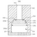
도 3 및 도 4는 본 발명의 일 실시예에 따른 압력 조절 부재를 설명하기 위한 도면.3 and 4 are views for explaining a pressure regulating member according to an embodiment of the present invention.
도 5 및 도 6은 일 실시예의 제 1 변형예에 따른 압력 조절 부재를 설명하기 위한 도면.5 and 6 are views for explaining the pressure regulating member according to the first modification of the embodiment.
도 7 및 도 8은 일 실시예의 제 2 변형예에 따른 압력 조절 부재를 설명하기 위한 도면이다.7 and 8 are views for explaining a pressure regulating member according to a second modification of the embodiment.
※도면의 주요 부재에 대한 부호의 설명※※ Explanation of code for main member of drawing ※
10, 12, 110, 112 : 로드 포트20, 120 : EFEM10, 12, 110, 112:
30, 32, 130, 132 : 로드락 챔버40, 140 : 진공 이송 모듈30, 32, 130, 132:
50, 52, 150, 152 : 프로세스 모듈134 : ATM 스위치50, 52, 150, 152: process module 134: ATM switch
135 : 압력 게이지200 : 압력 조절 부재135
300 : 개폐 수단310, 320 : 개구부300: opening and closing means 310, 320: opening
330 : 구동공간330 drive space
본 발명은 일반적으로 반도체 산업에서 사용되는 클러스터 툴(cluster tool)에서 진공 이송 모듈(TM, Transfer Module)과 클러스터 툴 전방 모듈(EFEM, Equipment Front End Module) 사이를 연결하는 로드락 챔버(load lock chamber) 및 이를 포함하는 클러스터 툴에 관한 것으로서, 보다 구체적으로는 EFEM과 로드락 챔버 사이의 압력차를 제거하기 위한 압력 조절 부재를 구비하는 로드락 챔버 및 이를 포함하는 클러스터 툴에 관한 것이다.The present invention relates to a load lock chamber for connecting between a vacuum transfer module (TM) and an equipment front end module (EFEM) in a cluster tool generally used in the semiconductor industry. And a cluster tool including the same, and more particularly, to a load lock chamber having a pressure adjusting member for removing a pressure difference between the EFEM and the load lock chamber, and a cluster tool including the same.
일반적으로 반도체 소자는, 기판인 웨이퍼 상에 여러 가지 물질을 박막 형태로 증착하고 이를 패터닝하여 구현되는데, 이를 위하여 증착 공정, 식각 공정, 세정 공정, 건조 공정 등 여러 단계의 서로 다른 공정이 요구된다. 이러한 각각의 공정에서 처리 대상물인 웨이퍼는 해당 공정의 진행에 최적의 환경을 가지고 있는 프로세스 모듈에 장착되어 처리되는데, 이와 같이 피처리물인 웨이퍼를 프로세스 모듈로 이송하여 프로세스를 진행할 수 있도록 하는 복합형 장치의 총칭이 클러스터 툴(cluster tool)이다.In general, a semiconductor device is implemented by depositing and patterning various materials on a wafer, which is a substrate, in a thin film form. For this purpose, different processes in various stages such as a deposition process, an etching process, a cleaning process, and a drying process are required. In each of these processes, the wafer to be processed is mounted and processed in a process module having an optimal environment for the processing of the process. In this way, a complex device that transfers the wafer to be processed into the process module and allows the process to proceed. The generic term for is the cluster tool.
이러한 클러스터 툴 내에는 오염되지 않은 진공 영역이 포함되므로, 통상 진 공 클러스터 툴이라 불리기도 하는데, 도 1은 일반적인 클러스터 툴의 개략적 평면도이다.Since such a cluster tool includes an uncontaminated vacuum area, it is also commonly referred to as a vacuum cluster tool. FIG. 1 is a schematic plan view of a general cluster tool.
도 1을 참조하면, 클러스터 툴은, 웨이퍼가 초기 또는 최종적으로 안착되어 적재되는 제 1 및 제 2 로드포트(loadport, 10, 12)와, 상기 제 1 및 제 2 로드포트(10, 12)에 위치하는 웨이퍼를 위치 정렬하여 이송하는 EFEM(Equipment Front End Module, 20)과, 상기 EFEM(20)으로부터 이송된 웨이퍼가 1차적으로 각각 적재되는 제 1 및 제 2 로드락 챔버(30, 32)와, 상기 제 1 및 제 2 로드락 챔버(30, 32)에 1차 적재된 웨이퍼를 각 해당 프로세스가 진행되는 프로세스 모듈(50, 52)로 이송하는 진공 이송 모듈(40)을 포함한다.Referring to FIG. 1, the cluster tool includes first and
이때, 전술한 EFEM(20)은 대기에 개방된 오염되지 않은 공간에 위치하여, 제 1 및 제 2 로드포트(10, 12)에 각각 적재된 웨이퍼를 이송하는 ATM 로봇(22)과, 이러한 ATM 로봇에 의해 이송된 웨이퍼를 위치 정렬하는 ATM 얼라이너(도시 않음)를 가지고 있어 웨이퍼의 이송 및 위치 정렬을 가능하게 한다.At this time, the above-described EFEM 20 is located in an uncontaminated space open to the atmosphere, and the
또한, EFEM(20)으로부터 이송된 웨이퍼가 1차 적재되는 제 1 및 제 2 로드락 챔버(30, 32)에는, 웨이퍼의 적재 위치인 메탈 쉘프(도시 않음)가 각각 구비되어, 이러한 메탈 쉘프 상에 웨이퍼가 1차적으로 적재된다. 이때 제 1 및 제 2 로드락 챔버(30, 32)와 EFEM(20) 사이의 영역에는 이들을 분리시키는 슬롯 밸브(31, 33)가 마련되어 있어 상기 제 1 및 제 2 로드락 챔버(30, 32) 내부를 진공 상태로 유지할 수 있다. 상기 제 1 및 제 2 로드락 챔버(30, 32) 내부를 대기압 및 진공 상태로 만들기 위해, 상기 제 1 및 제 2 로드락 챔버(30, 32)에는 ATM 스위치(34a, 34b)와 압력 게이지(35a, 35b)가 장착되어 있다. 또한, 상기 제 1 및 제 2 로드락 챔버(30, 32)의 각 메탈 쉘프에 적재된 웨이퍼는 진공 이송 모듈(40)에 위치하는 진공 로봇(41)에 의하여 각 프로세스 모듈(50, 52)의 장착 위치(51, 53)로 이송, 장착된다.In addition, the first and second
이와 같이, 상기 EFEM(20)은 대기 상태에 있고 상기 제 1 및 제 2 로드락 챔버(30, 32)는 진공 상태에 있게 된다. 프로세스 모듈(50, 52)에서 처리된 웨이퍼를 제 1 및 제 2 로드락 챔버(30, 32)로부터 상기 EFEM(20)으로 이송하기 위해서 상기 제 1 및 제 2 로드락 챔버(30, 32)에서는 벤트(vent)가 시작되며 상기 제 1 및 제 2 로드락 챔버(30, 32)가 대기압에 도달하면 ATM 스위치(34a, 34b)가 이를 감지하여 벤트가 종료된다.As such, the EFEM 20 is in a standby state and the first and second
그러나, 벤트가 종료되었을 때, 압력 게이지의 오차와 벤트하는 가스의 압력 및 벤트 과정에 의해서 로드락 챔버와 EFEM 사이에는 수 토르(torr)에서 수십 토르 (torr)범위의 압력차가 형성될 수 있다. 이러한 압력차가 형성되었을 때, 로드락 챔버의 슬롯 밸브를 개방하게 되면 한꺼번에 로드락 챔버와 EFEM 사이에 많은 량의 가스 또는 공기의 교환이 일어나 소음 및 입자(particle)를 발생시킨다. 이러한 입자는 로드락 챔버에서 대기하고 있는 웨이퍼에 오염물로 작용하게 되며 악영향을 주어 웨이퍼의 수율을 저하시킨다.However, when the vent is completed, a pressure difference in the range of several torr may be formed between the load lock chamber and the EFEM due to the error of the pressure gauge, the pressure of the venting gas, and the venting process. When such a pressure difference is formed, opening the slot valve of the load lock chamber causes a large amount of gas or air exchange between the load lock chamber and the EFEM at once to generate noise and particles. These particles act as contaminants to the wafer waiting in the load lock chamber and adversely affect the yield of the wafer.
따라서, 본 발명의 목적은 로드락 챔버와 EFEM 사이의 압력차로 인해 로드락 챔버의 슬롯 밸브의 개방시 압력 변화에 의한 가스 또는 공기의 흐름을 없애 입자의 발생을 제거할 수 있는 압력 조절 부재를 구비하는 로드락 챔버, 및 이를 포함하는 클러스터 툴을 제공하고자 하는 것이다.Accordingly, an object of the present invention is to provide a pressure regulating member capable of eliminating the generation of particles by eliminating the flow of gas or air due to the pressure change when opening the slot valve of the load lock chamber due to the pressure difference between the load lock chamber and the EFEM. To provide a load lock chamber, and a cluster tool comprising the same.
본 발명에 따른 적어도 하나의 로드락 챔버와, 상기 로드락 챔버에 연결된 클러스터 툴 전방 모듈 및 일단은 상기 로드락 챔버에 연결되고, 타단은 상기 클러스터 툴 전방 모듈에 연결되며 상기 로드락 챔버와 상기 클러스터 툴 전방 모듈 간의 압력차에 따라 이둘 간을 연통하는 압력 조절 수단을 포함하는 클러스터 툴을 제공한다.At least one load lock chamber, a cluster tool front module connected to the load lock chamber, and one end connected to the load lock chamber, and the other end connected to the cluster tool front module, wherein the load lock chamber and the cluster According to the pressure difference between the tool front module, there is provided a cluster tool including a pressure regulating means for communicating between the two.
여기서, 압력 조절 수단은, 구동 공간을 갖는 몸체와, 상기 로드락 챔버의 내부 공간과 상기 구동 공간을 연통하는 제 1 개구부와, 상기 클러스터 툴 전방 모듈의 내부 공간과 상기 구동 공간을 연통하는 제 2 개구부 및 상기 구동 공간 내에 마련되어 제 1 및 제 2 개구부의 압력에 따라 상기 제 1 및 제 2 개구부 사이의 연통을 제어하는 개폐 수단을 포함하는 것이 바람직하다. 상기의 제 1 및 제 2 개구부 중 어느 하나는 튜브 형태로 상기 몸체 내에 마련되고, 나머지 개구부는 적어도 일 단부가 중앙 영역에 다수의 관통공이 마련된 판 형상으로 제작되어 상기 몸체에 부착되며 다수의 관통공이 마련된 상기 중앙 영역이 상기 구동 공간에 노출되는 것이 효과적이다.Here, the pressure regulating means includes a body having a drive space, a first opening communicating the internal space of the load lock chamber with the driving space, and a second communicating the internal space of the cluster tool front module with the driving space. And opening and closing means provided in the opening and the drive space to control communication between the first and second openings in accordance with the pressure of the first and second openings. One of the first and second openings is provided in the body in the form of a tube, and the remaining openings are formed in a plate shape having a plurality of through holes provided in a central area of at least one end thereof and attached to the body. It is effective that the central region provided is exposed to the drive space.
물론 상기 개폐 수단은 제 1 및 제 2 개구부 중 적어도 어느 하나의 개구부 영역에 밀착하여 개구부의 연통을 차단하는 밀착면을 포함하는 것이 바람직하다.Of course, it is preferable that the opening and closing means includes a close contact surface in close contact with at least one of the opening regions of the first and second openings to block communication of the openings.
상기 개폐 수단은 적어도 하나의 관통공을 포함하되, 상기 관통공의 일 끝단이 상기 개구부와 접하는 밀착면 이외의 영역에 마련되는 것이 바람직하다.The opening and closing means includes at least one through hole, and one end of the through hole is preferably provided in a region other than the contact surface in contact with the opening.
상기의 제 1 개구부와 접하는 상기 구동공간 영역은 절두 원뿔 형상을 갖고, 상기 개폐 수단의 상기 밀착면 영역의 형상도 이와 대응되는 절두 원뿔 형상을 갖는 것이 바람직하다.Preferably, the driving space region in contact with the first opening portion has a truncated cone shape, and the shape of the contact surface region of the opening and closing means also has a truncated cone shape corresponding thereto.
상술한 개폐 수단이 자중에 의하여 상기 제 1 개구부에서 제 2 개구부 방향으로 이동하는 것이 바람직하다.It is preferable that the above-mentioned opening / closing means moves in the direction of the second opening portion from the first opening portion by its own weight.
상기의 개폐 수단으로 밸브를 사용하는 것이 바람직하다.It is preferable to use a valve as said opening / closing means.
상기 구동 공간 내에 마련되어 상기 개폐 수단을 지지하는 고정 부재를 더 포함하는 것이 효과적이다.It is effective to further include a fixing member provided in the drive space to support the opening and closing means.
상기 고정 부재는 상기 구동 공간 내에 링 형상으로 마련되고, 그 내부에 복수의 관통공이 마련되는 것이 바람직하다.It is preferable that the fixing member is provided in a ring shape in the drive space, and a plurality of through holes is provided therein.
상기 압력 조절 수단은 상기 로드락 챔버 또는 상기 클러스터 툴 전방 모듈과 일체로 제작되는 것이 바람직하다.The pressure adjusting means is preferably manufactured integrally with the load lock chamber or the cluster tool front module.
또한, 본 발명에 따른 적어도 하나의 로드락 챔버와 상기 로드락 챔버에 연결된 클러스터 툴 전방 모듈 및 상기 로드락 챔버와 상기 클러스터 툴 전방 모듈 간의 압력차에 따라 이둘 간을 연통하는 압력 조절 수단을 구비하는 클러스터 툴의 압력 조절 방법에 있어서, 처리가 완료된 기판을 상기 로드락 챔버에 이송하는 단계와, 상기 로드락 챔버를 벤트하는 단계와, 상기 압력조절 수단을 작동하여 상기 로드락 챔버와 상기 클러스터 툴 전방 모듈의 압력을 동일하게 조절하는 단계와, 상기 로드락 챔버의 상기 기판을 상기 클러스터 툴 전방 모듈로 이송하는 단계를 포함하는 클러스터 툴의 압력 조절 방법을 제공한다.In addition, at least one load lock chamber and a cluster tool front module connected to the load lock chamber and pressure control means for communicating between the two according to the pressure difference between the load lock chamber and the cluster tool front module A pressure adjusting method of a cluster tool, the method comprising: transferring a processed substrate to the load lock chamber, venting the load lock chamber, and operating the pressure regulating means in front of the load lock chamber and the cluster tool. And equally adjusting the pressure of the module, and transferring the substrate of the load lock chamber to the front of the cluster tool.
상기의 로드락 챔버와 상기 클러스터 툴 전방 모듈의 압력을 동일하게 조절하는 단계는, 상기 압력 조절 수단에 의해 상기 로드락 챔버와 상기 클러스터 툴 전방 모듈이 연통되어 압력이 동일해지는 단계를 더 포함하는 것이 바람직하다.The step of equally adjusting the pressure of the load lock chamber and the cluster tool front module further includes the step of communicating the load lock chamber and the cluster tool front module by the pressure adjusting means so that the pressure is the same. desirable.
이하, 첨부된 도면을 참조하여 본 발명의 실시예들을 더욱 상세히 설명하기로 한다. 그러나 본 발명은 이하에서 개시되는 실시예들에 한정되는 것이 아니라 서로 다른 다양한 형태로 구현될 수 있으며, 본 실시예들은 단지 본 발명의 개시가 완전하도록 하며, 본 발명이 속하는 기술분야에서 통상의 지식을 가진 자에게 발명의 범주를 완전하게 알려주기 위해 제공되는 것이다. 도면 상에서 동일 부호는 동일한 부재를 지칭한다.Hereinafter, with reference to the accompanying drawings will be described embodiments of the present invention in more detail. However, the present invention is not limited to the embodiments disclosed below, but may be embodied in various forms, and the present embodiments merely make the disclosure of the present invention complete, and the general knowledge in the art to which the present invention pertains. It is provided to fully inform the person of the scope of the invention. Like numbers refer to like elements in the drawings.
도 2는 본 발명의 일 실시예에 따른 로드락 챔버를 포함하는 클러스터 툴의 개략적 평면도이다.2 is a schematic plan view of a cluster tool including a load lock chamber in accordance with an embodiment of the present invention.
도 2를 참조하면, 본 실시예의 상기 클러스터 툴은 웨이퍼가 초기 또는 최종적으로 안착되어 적재되는 제 1 및 제 2 로드포트(loadport, 110, 112)와, 상기 제 1 및 제 2 로드포트(110, 112)에 위치하는 웨이퍼를 위치 정렬하여 이송하는 EFEM(Equipment Front End Module, 120)과, 상기 EFEM(120)으로부터 이송된 웨이퍼 가 1차적으로 각각 적재되는 제 1 및 제 2 로드락 챔버(130, 132)와, 상기 제 1 및 제 2 로드락 챔버(130, 132)에 1차 적재된 웨이퍼를 각 해당 프로세스가 진행되는 프로세스 모듈(150, 152)로 이송하는 진공 이송 모듈(140)을 포함한다.Referring to FIG. 2, the cluster tool of the present embodiment may include first and
이때, 상기 EFEM(120)은 대기에 개방된 오염되지 않은 공간에 위치하여, 제 1 및 제 2 로드포트(110, 112)에 각각 적재된 웨이퍼를 이송하는 ATM 로봇(122)과, 이러한 ATM 로봇(122)에 의해 이송된 웨이퍼를 위치 정렬하는 ATM 얼라이너(미도시)를 가지고 있어 웨이퍼의 이송 및 위치 정렬을 가능하게 한다.In this case, the
또한, 상기 EFEM(120)으로부터 이송된 웨이퍼가 1차 적재되는 제 1 및 제 2 로드락 챔버(130, 132)에는, 웨이퍼의 적재 위치인 메탈 쉘프(도시 않음)가 각각 구비되어, 이러한 메탈 쉘프 상에 웨이퍼가 1차적으로 적재된다. 이때 제 1 및 제 2 로드락 챔버(130, 132)와 EFEM(120) 사이의 영역에는 이들을 분리시키는 슬롯 밸브(131, 133)가 마련되어 있어 상기 제 1 및 제 2 로드락 챔버(130, 132) 내부를 진공 상태로 유지할 수 있다. 또한, 상기 제 1 및 제 2 로드락 챔버(130, 132)에는 ATM 스위치(134a, 134b)와 압력 게이지(135a, 135b)가 장착되어 있다. 상기 제 1 및 제 2 로드락 챔버(130, 132)는 각각 상기 제 1 및 제 2 로드락 챔버(130, 132)와 EFEM(120)을 연통시키는 압력 조절 부재(200)를 포함한다.In addition, the first and second
상기 압력 조절 부재(200)는 상기 제 1 및 제 2 로드락 챔버(130, 132)와 EFEM(120)을 연통시켜 상기 제 1 및 제 2 로드락 챔버(130, 132)와 EFEM(120) 내부의 압력을 동일하게 만든다.The
이때, 상기 제 1 로드락 챔버(130) 또는 제 2 로드락 챔버(132)는 진공 상태 에 있고 EFEM(120)은 대기압 상태에 있게 된다. 이와 같이 이들 내부의 압력 차이로 인해 제 1 로드락 챔버(130) 또는 제 2 로드락 챔버(132)를 대기압 상태로 만들기 위해 제 1 로드락 챔버(130) 또는 제 2 로드락 챔버(132)의 벤트가 시작되며 상기 제 1 로드락 챔버(130) 또는 제 2 로드락 챔버(132)가 대기압에 도달하면 ATM 스위치(134a, 134b)가 이를 감지하여 벤트가 종료된다. 그러나 이 경우에도 압력 게이지의 오차와 벤트하는 가스의 압력 및 벤트 과정에 따라 제 1 로드락 챔버(130) 또는 제 2 로드락 챔버(132)의 내부가 대기압(즉, EFEM 내부의 압력)보다 높거나 낮을 수 있다. 이러한 상태에서 전술한 바와 같이 제 1 로드락 챔버(130) 또는 제 2 로드락 챔버(132)의 슬롯 밸브(131, 133)를 개방하게 되면 압력 차로 인한 제 1 로드락 챔버(130) 또는 제 2 로드락 챔버(132) 내부에 소음 및 입자의 발생을 초래하여 고 청정도를 요구하는 웨이퍼의 수율에 악영향을 줄 뿐만 아니라 웨이퍼의 정렬이 틀어지거나 심지어는 웨이퍼가 미끌어지는 현상이 발생한다. 따라서, 제 1 로드락 챔버(130) 및 제 2 로드락 챔버(132)와, EFEM(120)압력을 동일하게 설정하여야 하고, 이를 위해 제 1 및 제 2 로드락 챔버(130, 132)와 EFEM(120)사이에는 압력 조절 부재(200)가 마련되는 것이 바람직하다. 본 실시예에서는 제 1 및 제 2 로드락 챔버(130, 132) 각각에 압력 조절 부재(200)를 배치하였다. 상기 압력 조절 부재(200)는 EFEM(120)과 제 1 로드락 챔버(130) 또는 제 2 로드락 챔버(132)를 연통시키도록 EFEM(120)과 마주보는 제 1 로드락 챔버(130) 또는 제 2 로드락 챔버(132)의 본체에 형성되어 있다. 상기 압력 조절 부재(200)에 대해서는 후술한다.At this time, the first
상기 클러스터 툴의 작동 과정에 대해 설명하면 다음과 같다.An operation process of the cluster tool will be described below.
먼저, 제 1 로드포트(110) 또는 제 2 로드포트(112)에 초기 적재된 다수의 웨이퍼가 EFEM(120)의 ATM 로봇(122)에 의하여 하나씩 이송되어, ATM 얼라이너에 놓이게 되면, ATM 얼라이너는 이러한 웨이퍼를 제 1 프로세스 모듈(150) 또는 제 2 프로세스 모듈(152)의 장착 위치(151, 153)에 정확하게 놓이도록 위치 정렬된다. 이후 다시 ATM 로봇(122)이 위치 정렬된 웨이퍼를 제 1 및 제 2 로드락 챔버(130, 132) 내의 메탈 쉘프(도시 않음)로 하나씩 이송하여 적재한다. 이와 같은 과정을 반복하여 제 1 로드락 챔버(130) 및 제 2 로드락 챔버(132)의 메탈 쉘프로 웨이퍼가 모두 이송되면, 제 1 및 제 2 로드락 챔버(130, 132)의 슬롯 밸브(131, 133)가 닫힌 후 입자가 들어가지 않도록 펌핑을 개시하여 진공 상태를 유지하게 된다. 이후, 진공 이송 모듈(140)에 위치하는 진공 로봇(141)에 의하여 제 1 로드락 챔버(130) 또는 제 2 로드락 챔버(132)의 쉘프에 적재된 웨이퍼가 한 장씩 제 1 또는 제 2 프로세스 모듈(150, 152)로 공급되고, 제 1 또는 제 2 프로세스 모듈(150, 152)은 해당 프로세스를 진행하게 된다.First, when a plurality of wafers initially loaded in the
이후, 제 1 또는 제 2 프로세스 모듈(150, 152)에서 웨이퍼의 처리가 완료되면, 웨이퍼는 전술한 과정의 역순, 즉 진공 로봇(141)에 의해 각 프로세스 모듈(150, 152)로부터 다시 제 1 로드락 챔버(130) 또는 제 2 로드락 챔버(132)의 메탈 쉘프로 회송되어 적재되고, 제 1 로드락 챔버(130)나 제 2 로드락 챔버(132)가 대기압으로 벤트되어, 제 1 로드락 챔버(130) 또는 제 2 로드락 챔버(132)에 장착되어 있는 ATM 스위치(134a, 134b)가 동작을 하게 되어 벤트가 완료되는데, 이때 발생하는 제 1 로드락 챔버(130) 또는 제 2 로드락 챔버(132)와 EFEM(120) 사이의 압력차는 압력 조절 부재(200)에 의해서 제 1 로드락 챔버(130) 또는 제 2 로드락 챔버(132)와 EFEM(120) 사이의 압력을 동일하게 한다. 그 후, 슬롯 밸브(131, 133)를 개방하고 웨이퍼를 제 1 로드락 챔버(130) 또는 제 2 로드락 챔버(132)로부터 EFEM(120)을 통해 제 1 로드포트 또는 제 2 로드포트(110, 112)로 이송시킨다. 이처럼, 본 발명은 로드락 챔버(130, 132)와 EFEM(120)의 압력을 동일하게 한 후 슬롯 밸브(131, 133)를 개방하므로, 로드락 챔버(130, 132)와 EFEM(120) 사이에서 급격한 유체 흐름이 발생하지 않아 소음 및 입자의 발생을 방지할 수 있다. 상기의 과정을 반복 수행함으로써 다수의 웨이퍼의 프로세싱이 완료된다.Subsequently, when the processing of the wafer is completed in the first or
도 3 및 도 4는 본 발명의 일 실시예에 따른 압력 조절 부재를 설명하기 위한 도면이다.3 and 4 are views for explaining a pressure regulating member according to an embodiment of the present invention.
도 3 및 도 4를 참조하면, 본 발명의 일 실시예에 따른 압력 조절 부재(200)는 상기 몸체(301)와, 상기 몸체(301) 내에 마련되어 외부 공간과 연통하는 제 1 개구부(310)와 제 2 개구부(320)를 포함하고, 상기 제 1 및 제 2 개구부(310, 320) 사이에는 구동 공간(330)이 형성되고, 상기 구동 공간(330) 내에 개폐 수단(300)이 움직여 제 1 및 제 2 개구부(310, 320)의 개폐를 조절한다.3 and 4, the
여기서, 상기 몸체(301)는 로드락 챔버(130, 132) 또는 EFEM(120)과 일체로 제작될 수도 있다. 상기 제 1 및 제 2 개구부(310, 320) 중 어느 하나는 로드락 챔버(130, 132)의 내부 공간과 연통하고, 나머지 하나는 EFEM(120)의 내부 공간과 연통된다.Here, the
상기의 제 1 개구부(310)는 도면에 도시된 바와 같이 관통홀 형태로 구성된다. 제 2 개구부(320)는 도면에 도시된 바와 같이 적어도 중심 영역에 복수의 관통홀이 마련된 판 형상으로 제작된다. 상기 구동 공간(330)은 제 1 및 제 2 개구부(310, 320) 사이에 관통홀 형상으로 마련되고, 제 1 개구부(310)와 접속되는 관통홀 영역의 면적이 제 2 개구부(320)와 접속하는 관통홀의 면적보다 작은 것이 바람직하다.The
구동 공간(330)은 상측면(331)과 하측면(332) 그리고, 상측면(331)과 하측면(332) 사이에 측벽면(333a, 333b; 333)을 포함한다. 이때, 하측면(332)은 제 1 개구부(310)에 접속되고, 상측면(331)은 제 2 개구부(320)에 접속된다. 상기 상측면(331)을 통해 제 2 개구부(320)의 관통홀이 구동 공간(330)에 모두 노출되고, 하측면(332)를 통해 제 1 개구부(310)의 관통홀이 구동 공간(330)에 노출된다. 앞서 설명한 바와 같이 하측면(332)에 비하여 상측면(331)의 면적이 넓기 때문에 상기 측벽면(333)은 소정의 기울기를 갖는 영역으로 존재한다. 도면에서와 같이 측벽면(333)은 상측면(331)과 접하여 이와 수직하에 연장된 제 1 측벽면(333a)과 상기 제 1 측벽면(333a)에서 소정의 기울기를 갖고 하측면(332)으로 연장된 제 2 측벽면(333b)을 포함한다.The driving
개폐 수단(300)은 구동공간(330) 내에서 이동하여 제 1 개구부(310) 및 제 2 개구부(320)의 관통홀을 차폐할 수 있는 형상으로 제작한다.The opening and closing means 300 is manufactured in a shape capable of moving in the driving
즉, 개폐 수단(300)의 전면부에는 상기 제 1 개구부(310)의 관통홀을 막을 수 있을 정도의 면으로 마련되고, 후면부에는 상기 제 2 개구부(320)의 관통홀을 모두 막을 수 있을 정도의 면이 마련된다. 바람직하게는 도 3 및 도 4에 도시된 바와 같이 상기 개폐 수단(300)은 그 단면이 대략 사다리꼴 형태로 제작된다. 여기서, 사다리꼴의 윗변은 구동 공간(330)의 하측면(332)과 대응되고, 아랫변은 제 2 개구부의 관통홀 형성 영역과 대응된다. 그리고, 다른 두변은 구동 공간(330)의 제 2 측벽면(333b)와 대응된다. 이를 통해 개폐 수단(300)이 도 3의 (a)에서와 같이 구동 공간(330)의 아래 끝단에 위치하는 경우에는 제 1 개구부(310)에 밀착되고, 구동 공간(330)의 제 2 측벽면(333b)에 밀착되어 제 1 개구부(310)을 차폐한다. 또한, 도 3의 (b)에서와 같이 구동 공간(330)의 상측 끝단에 위치하는 경우에는 제 2 개구부(310)에 밀착되어 제 2 개구부(320)을 차폐한다. 도 4와 같이 상기 개폐 수단(300)이 구동 공간(330)의 중심영역에 위치하는 경우에는 상기 구동 공간(330)과 국부적으로 밀착되어 제 1 및 제 2 개구부(310, 320) 사이에 연통공간을 마련한다. 이때, 만일 상기 개폐 수단(300)의 자중을 이용하여 제 1 및 제 2 개구부(310, 320)를 개폐하는 경우에는 본 실시예의 압력 조절 부재(200)는 지면에 수직하게 배치되는 것이 바람직하다. 그리고, 상기 개폐 수단(300)과 제 1 및 제 2 개구부의 경계면의 개폐를 더욱 확실히 하기 위해 상기 개폐 수단(300)에 O-링 등의 밀봉 부재(350)가 마련되는 것이 효과적이다. 여기서, 상기의 구동 공간(330)이 그 상부에 절두 원뿔 형상을 갖는 원형 통 형상으로 제작될 경우 상기 개폐 수단(300)은 상기 절두 원뿔 형상에 대응되는 절두 원뿔 형상으로 제작되는 것이 바람직하다. 그리고, 구동 공간(330)이 그 상부에 절두 사각 뿔 형상을 갖는 사각 통 형상으로 제작될 경우에는 상기 개폐 수단(300)은 절두 사각 뿔 형상으로 제작되는 것이 바 람직하다.That is, the front portion of the opening and closing means 300 is provided with a surface sufficient to block the through hole of the
하기에서는 이러한 압력 조절 부재(200)의 압력 조절 과정에 대해 설명하면 다음과 같다.Hereinafter, the pressure adjusting process of the
여기서, 제 1 개구부(310)가 로드락 챔버(130, 132)의 내부 공간에 접속되고, 제 2 개구부(320)가 EFEM(120)의 내부 공간에 접속됨을 일예로하여 설명한다.Here, the
EFEM(120)은 항상 대기압 상태에 있고, 로드락 챔버(130, 132)의 압력이 대기압보다 낮으면 EFEM(120)의 압력이 로드락 챔버(130, 132)의 압력보다 높은 상태이이다. 이경우, 압력 조절 부재(200) 내부의 개폐 수단(300)은 압력차에 의해 제 1 개구부(310) 쪽으로 밀려가 제 1 개구부(310)를 차폐한다. 이를 통해 제 1 개구부(310) 및 제 2 개구부(320) 사이의 연통 공간이 형성되지 않게 된다.The
이후, 상기 로드락 챔버(130, 132)의 압력이 대기압이 될 때까지 로드락 챔버(130, 132)를 계속 밴트시키면 로드락 챔버(130, 132)와 EFEM(120)의 압력이 유사해지게 된다. 이와 같이 둘 사이의 압력 차가 줄어들 경우, 어느 순간부터 개폐 수단(300)의 자중에 의해 개폐 수단(300)이 상기 제 1 개구부(310)에서부터 이격되게 된다. 이를 통해 제 1 개구부(310) 및 제 2 개구부(320) 사이에는 연통 공간이 형성된다. 따라서, 이러한 연통 공간을 통해 제 1 개구부(310) 및 제 2 개구부(320) 사이에 압력 평행이 형성된다.Thereafter, if the
이와 같이 EFEM(120)과 로드락 챔버(130, 132) 간에 압력이 평형하게 되면 슬롯 노즐(131, 133)을 개방시켜 웨이퍼를 로드락 챔버(130, 132)로부터 EFEM(120)을 통해 로드 포트(110, 112)로 이송시킬 수 있게 된다.When the pressure is balanced between the
물론 본 실시예는 이에 한정되지 않고, 상기 제 1 개구부(310)가 EFEM(120)의 내부 공간에 접속될 수도 있고, 제 2 개구부(320)가 로드락 챔버(130, 132)에 접속될 수도 있다.Of course, the present embodiment is not limited thereto, and the
도 5 및 도 6은 일 실시예의 제 1 변형예에 따른 압력 조절 부재를 설명하기 위한 도면이다.5 and 6 are views for explaining the pressure regulating member according to the first modification of the embodiment.
도 5 및 도 6을 참조하면, 본 변형예에 따른 압력 조절 부재(200)는 몸체(301)와, 상기 몸체에 마련된 제 1 및 제 2 개구부(310, 320)와, 상기 제 1 및 제 2 개구부(310, 320) 사이에 마련된 구동공간(330)과, 상기 구동 공간(330) 내에 마련되어 상기 제 1 및 제 2 개구부(310, 320)간의 연동을 제어하는 개폐 수단(300)과, 구동 공간(330) 내에 마련되어 개폐 수단(300)의 이동을 제어하고, 연통된 제 1 및 제 2 개구부(310, 320) 사이의 공기 흐름을 유도하는 고정부재(360)을 포함한다.5 and 6, the
상기의 고정부재(360)는 상기 구동 공간(330)의 제 1 내측벽(333a) 영역에 링 형상으로 마련되고, 링의 내측에는 복수의 관통홀이 마련되는 것이 바람직하다. 상기 고정 부재(360)은 제 1 개구부(310)과 인접한 영역에 마련되는 것이 바람직하다. 이를 통해 개폐 수단(300)의 과도한 움직임을 줄일 수 있다. 그리고, 링 형상의 고정 부재(360)의 내측 개구 영역은 상기 개폐 수단(300)의 후면부의 면적보다 작은 것이 바람직하다. 이를 통해 개폐 수단(300)이 상기 고정 부재(360)을 이탈하는 것을 방지할 수 있다.The fixing
이때, 상기 구동 공간(330)은 제 2 개구부(320)과 접속되는 상측면(331)과, 제 1 개구부(310)에 접속되는 하측면(332)과, 상기 상측면(332)에서부터 수직하게 연장된 제 1 측벽면(333a)과, 상기 하측면(332)에서부터 일정한 기울기를 갖고 연장된 제 2 측벽면(333b)과, 상기 제 1 및 제 2 측벽면(333a, 333b) 간을 연결하는 제 3 측벽면(333c)을 포함한다. 여기서, 상기 제 3 측벽면(333c)은 도면에 도시된 바와 같이 제 1 측벽면(333a)와 수직하게 연장된다. 그리고, 제 2 측벽면(333b)의 높이과 개폐 수단(300)의 높이를 동일하게 제작할 수도 있다. 여기서, 상기 고정 부재(360)은 상기 제 1 측벽면(333a)에 마련된다.In this case, the driving
상술한 압력 조절 부재(200)의 동작을 간략히 설명하면 다음과 같다.The operation of the
제 1 개구부(310)가 로드락 챔버(130, 132)의 내부 공간에 접속되고, 제 2 개구부(320)가 EFEM(120)의 내부 공간에 접속됨을 일예로 설명한다.As an example, the
로드락 챔버(130, 132)가 진공 상태이고, EFEM(120)이 대기압 상태이면 이둘 사이에는 압력차가 발생한다. 이러한 압력차로 인해 상기 구동 공간(330) 내부의 개폐 수단(300)은 도 5에 도시된 바와 같이 제 1 개구부(310)에 밀착된다. 이를 통해 제 1 개구부(310)와 제 2 개구부(320) 사이의 공기 흐름을 차폐한다. 이를 통해 로드락 챔버(130, 132)는 계속적으로 진공을 유지할 수 있게 된다. 한편, 로드락 챔버(130, 132)의 압력을 대기압과 유사하게 되도록 밴트를 수행하게 되면 로드락 챔버(130, 132)와 EFEM(120)의 압력차가 줄어들게 된다. 여기서 로드락 챔버(130, 132) 및 EFEM(120)의 압력차에 의해 제 1 개구부(310)에 밀착되어 있던 개폐 수단(300)이 도 6에 도시된 바와 같이 이로부터 이격되게 되고 이로인해 제 1 개구부(310)과 제 2 개구부(320) 사이에 연통 공간이 마련되어 압력 평행이 이루어진 다. 이때, 개폐 수단(300)은 자중에 의해 고정부재(360)에 밀착되고, 고정 부재(360)의 복수의 관통홀에 의해 제 1 개구부(310)와 제 2 개구부(320) 사이에 연통 공간이 형성된다. 이와 같이 개폐 수단(300)이 자중에 의해 고정 부재(360)에 밀착되기 위해서는 구동 공간(330)의 상측면(331)이 지면 영역으로 향하도록 배치되는 것이 효과적이다.When the
도 7 및 도 8은 일 실시예의 제 2 변형예에 따른 압력 조절 부재를 설명하기 위한 도면이다.7 and 8 are views for explaining a pressure regulating member according to a second modification of the embodiment.
도 7 및 도 8을 참조하면, 본 변형예에 따른 압력 조절 부재(200)는 몸체(301)와, 상기 몸체에 마련된 제 1 및 제 2 개구부(310, 320)와, 상기 제 1 및 제 2 개구부(310, 320) 사이에 마련된 구동공간(330)과, 상기 구동 공간(330) 내에 마련되어 상기 제 1 및 제 2 개구부(310, 320)간의 연동을 제어하는 개폐 수단(300)과, 상기 개폐 수단(300)의 일측에 마련된 연통 공(370)과, 상기 개폐 수단(300)을 고정하는 링 형상의 고정 부재(360)을 포함한다.7 and 8, the
상기의 고정 부재(360)는 구동 공간(330)의 제 1 측벽면(333a)에 링 형태로 마련되는 것이 바람직하다. 이때 고정부재(360)은 몸체(301)와 일체로 제작될 수 있다. 본 변형예에서는 상기 구동공간(330)의 상측면(331)의 면적과 개폐 수단(300)의 후면부의 면적이 동일한 것이 바람직하다.The fixing
상기의 개폐 수단(300)은 복수의 연통 공(370)을 포함하되, 상기 개폐 수단(300)이 상기 제 1 개구부(310)에 밀착되었을 경우 상기 개폐 수단(300)과 구동 공간(330)의 내측면들이 만나는 영역에서 개폐 수단(300)의 후면부 즉, 아랫변 영 역까지 연통된 복수의 연통공(370)을 포함한다.The opening and closing means 300 includes a plurality of
여기서, 상기 연통 공(370)은 도면에 도시된 바와 같이 개폐 수단(300)의 윗변과 아랫변을 연결하는 사선형 변에서부터 아랫변까지 관통된 형상으로 제작하는 것이 바람직하다.Here, the
상술한 고정 부재(360)는 개폐 수단(300)의 연통 공(370)을 차폐하지 않는 범위내에서 다양하게 제작될 수 있다.The fixing
상술한 압력 조절 부재(200)의 동작을 간략히 설명하면 다음과 같다.The operation of the
제 1 개구부(310)가 로드락 챔버(130, 132)의 내부 공간에 접속되고, 제 2 개구부(320)가 EFEM(120)의 내부 공간에 접속됨을 일예로 설명한다.As an example, the
로드락 챔버(130, 132)가 진공 상태이고, EFEM(120)이 대기압 상태이면 이둘 사이에는 압력차가 발생한다. 이러한 압력차로 인해 상기 구동 공간(330) 내부의 개폐 수단(300)은 도 7에 도시된 바와 같이 제 1 개구부(310)에 밀착된다. 이때, 개폐 수단(300)의 연통공(370)의 전단영역 즉, 사선형 변 영역이 구동 공간(330)의 제 2 측벽면(333b)에 밀착되어 있기 때문에 제 1 개구부(310)와 제 2 개구부(320) 사이의 공기 흐름을 차폐한다. 이를 통해 로드락 챔버(130, 132)는 계속적으로 진공을 유지할 수 있게 된다. 한편, 로드락 챔버(130, 132)의 압력을 대기압과 유사하게 되도록 밴트를 수행하게 되면 로드락 챔버(130, 132)와 EFEM(120)의 압력차가 줄어들게 된다. 여기서 로드락 챔버(130, 132) 및 EFEM(120)의 압력차에 의해 제 1 개구부(310)에 밀착되어 있던 개폐 수단(300)이 도 8에 도시된 바와 같이 이로부터 이격되게 되고 이로인해 제 1 개구부(310)과 제 2 개구부(320) 사이에 연통 공간이 마련되어 압력 평행이 이루어진다. 즉, 개폐 수단(300)이 이격되면 그 이격된 사이 영역으로 압력 교환이 이루어지게 된다. 그리고, 자중에 의해 개폐 수단(300)이 고정 부재(360)에 밀착되는 경우에는 개폐 수단의 연통 공(370)에 의해 제 1 및 제 2 개구부(310, 320) 사이에 연통 공간이 마련된다. 이를 통해 로드락 챔버(130, 132)의 압력을 EFEM(120)의 압력과 동일하게 할 수 있다.When the
여기서, 고정 부재(360)과 개폐 수단(300) 사이의 간격이 1 내지 10mm 인 것이 바람직하다. 상기 사이 간격이 크면 펌핑에 의해 개폐 수단(300)이 제 1 개구부(310) 쪽으로 용이하게 밀려갈 수 없게 된다.Here, the interval between the fixing
본 실시예의 도 2에서는 상술한 압력 조절 부재(200)가 로드락 챔버(130, 132)내에 마련됨을 도시하였지만, 이에 한정되지 않고, EFEM(120)에 마련하고, 상기 압력 조절 부재(200)의 제 1 또는 제 2 개구부(310, 320)가 로드락 챔버(130, 132)의 내부공간에 접속되도록 할 수 있다. 또한, 상기 로드락 챔버(130, 132)와 EFEM(120)의 외측에 마련할 수도 있다. 그리고, 상기 압력 조절 부재(200)는 로드락 챔버(130, 132) 또는 EFEM(120)과 일체로 제작될 수도 있다.In FIG. 2 of the present embodiment, the above-described
또한, 본 발명은 상술한 설명에 한정되지 않고, 다양한 변형예가 가능하다. 즉, 상술한 압력 조절 부재(200)로 밸브(미도시)를 사용하여 로드락 챔버(130, 132)와 EFEM(120)간의 압력을 일정하게 유지할 수 있다. 즉 로드락 챔버(130, 132)가 진공상태일 경우에는 밸브를 차단하였다가 로드락 챔버(130, 132)의 압력이 대기압 상태일 경우에는 밸브를 오픈하여 로드락 챔버(130, 132)와 EFEM(120) 간의 압력 평행을 유지할 수 있다. 이때, 로드락 챔버(130, 132)의 압력을 1차적으로 압 력게이지를 이용하여 EFEM(120)의 압력과 동일하게 조절하고, 2차로 밸브를 동작시켜 EFEM(120)의 압력과 동일하게 조절할 수 있다.In addition, the present invention is not limited to the above description, and various modifications are possible. That is, the
상술한 바와 같이 본 발명은 로드락 챔버와 EFEM 사이를 압력에 따라 연통시키는 압력 조절 수단을 통해 로드락 챔버와 EFEM 둘 사이의 압력을 동일하게 유지할 수 있다.As described above, the present invention can maintain the same pressure between the load lock chamber and the EFEM through pressure control means for communicating the pressure between the load lock chamber and the EFEM according to the pressure.
또한, 상기 압력 조절 수단 내부에 개폐 수단을 두어 상기 로드락 챔버가 진공시에는 로드락 챔버와 EFEM 간의 연통을 차단하고, 로드락 챔버가 대기압 상태일 경우에는 로드락 챔버와 EFEM 간을 연통시킬 수 있다.In addition, the opening and closing means is provided inside the pressure adjusting means to block communication between the load lock chamber and the EFEM when the load lock chamber is vacuum, and communicate between the load lock chamber and the EFEM when the load lock chamber is at atmospheric pressure. have.
또한, 압력 조절 수단을 통해 로드락 챔버와 EFEM 간의 대기압 상태의 압력 평행을 유지시켜 로드락 챔버 및 EFEM 간의 압력 차에 의한 가스 또는 공기의 흐름을 방지할 수 있다.In addition, it is possible to prevent the flow of gas or air due to the pressure difference between the load lock chamber and the EFEM by maintaining the pressure parallel of the atmospheric pressure state between the load lock chamber and the EFEM through the pressure adjusting means.
본 발명을 첨부 도면과 전술된 바람직한 실시예를 참조하여 설명하였으나, 본 발명은 그에 한정되지 않으며, 후술되는 특허청구범위에 의해 한정된다. 따라서, 본 기술분야의 통상의 지식을 가진 자라면 후술되는 특허청구범위의 기술적 사상에서 벗어나지 않는 범위 내에서 본 발명을 다양하게 변형 및 수정할 수 있다.Although the present invention has been described with reference to the accompanying drawings and the preferred embodiments described above, the present invention is not limited thereto but is limited by the following claims. Accordingly, those skilled in the art will appreciate that various modifications and changes may be made thereto without departing from the spirit of the following claims.
Claims (13)
Translated fromKoreanPriority Applications (1)
| Application Number | Priority Date | Filing Date | Title |
|---|---|---|---|
| KR1020060064673AKR101217516B1 (en) | 2006-07-11 | 2006-07-11 | cluster tool |
Applications Claiming Priority (1)
| Application Number | Priority Date | Filing Date | Title |
|---|---|---|---|
| KR1020060064673AKR101217516B1 (en) | 2006-07-11 | 2006-07-11 | cluster tool |
Publications (3)
| Publication Number | Publication Date |
|---|---|
| KR20080006035A KR20080006035A (en) | 2008-01-16 |
| KR101217516B1true KR101217516B1 (en) | 2013-01-02 |
| KR101217516B9 KR101217516B9 (en) | 2025-02-14 |
Family
ID=39219916
Family Applications (1)
| Application Number | Title | Priority Date | Filing Date |
|---|---|---|---|
| KR1020060064673AActiveKR101217516B1 (en) | 2006-07-11 | 2006-07-11 | cluster tool |
Country Status (1)
| Country | Link |
|---|---|
| KR (1) | KR101217516B1 (en) |
Families Citing this family (2)
| Publication number | Priority date | Publication date | Assignee | Title |
|---|---|---|---|---|
| CN109671643B (en)* | 2013-08-12 | 2023-11-28 | 应用材料公司 | Substrate processing systems, devices and methods with factory interface environmental control |
| CN107004624B (en) | 2014-11-25 | 2020-06-16 | 应用材料公司 | Substrate processing system, apparatus and method with substrate carrier and clean chamber environmental control |
Citations (2)
| Publication number | Priority date | Publication date | Assignee | Title |
|---|---|---|---|---|
| KR100275807B1 (en)* | 1995-04-20 | 2000-12-15 | 히가시 데쓰로 | APPARATUS AND METHOD FOR REGULATING PRESSURE IN TWO CHAMBERS |
| KR20020015672A (en)* | 2000-08-22 | 2002-02-28 | 에이에스엠 저펜 가부시기가이샤 | Semiconductor processing module and apparatus |
- 2006
- 2006-07-11KRKR1020060064673Apatent/KR101217516B1/enactiveActive
Patent Citations (2)
| Publication number | Priority date | Publication date | Assignee | Title |
|---|---|---|---|---|
| KR100275807B1 (en)* | 1995-04-20 | 2000-12-15 | 히가시 데쓰로 | APPARATUS AND METHOD FOR REGULATING PRESSURE IN TWO CHAMBERS |
| KR20020015672A (en)* | 2000-08-22 | 2002-02-28 | 에이에스엠 저펜 가부시기가이샤 | Semiconductor processing module and apparatus |
Also Published As
| Publication number | Publication date |
|---|---|
| KR20080006035A (en) | 2008-01-16 |
| KR101217516B9 (en) | 2025-02-14 |
Similar Documents
| Publication | Publication Date | Title |
|---|---|---|
| US8382088B2 (en) | Substrate processing apparatus | |
| CN110809820B (en) | Side storage compartment, equipment front end module and method for processing substrate | |
| US20020159864A1 (en) | Triple chamber load lock | |
| US20040144316A1 (en) | Apparatus for processing a substrate | |
| US20070051314A1 (en) | Movable transfer chamber and substrate-treating apparatus including the same | |
| US20070023322A1 (en) | Apparatus and method for manufacturing semiconductor devices | |
| US7371683B2 (en) | Method for carrying object to be processed | |
| KR19990072493A (en) | Device and Method for Load Locking for Semiconductor Processing | |
| US20170271187A1 (en) | Load lock chamber and the cluster tool system using the same | |
| US12080572B2 (en) | Substrate processing apparatus | |
| US12198952B2 (en) | Substrate processing apparatus | |
| KR20220023710A (en) | Device for transferring substrate, system for processing substrate, and method of processing substrate | |
| KR100839911B1 (en) | Substrate processing equipment | |
| KR101217516B1 (en) | cluster tool | |
| US11862506B2 (en) | Substrate processing system, vacuum substrate transfer module, and substrate transfer method | |
| US20220148857A1 (en) | Detection device, processing system, and transfer method | |
| US20240309966A1 (en) | Gate valve and driving method | |
| US11791180B2 (en) | Substrate transfer system and load lock module | |
| KR102344253B1 (en) | Side storage unit and system for treating substrate with the side storage unit | |
| KR100439036B1 (en) | Semiconductor manufacturing equipment | |
| KR20120084063A (en) | Load lock chamber having buffer chamber and apparatus for treating substrate including the same | |
| KR101184596B1 (en) | Apparatus for transfering wafer and method for operating the same | |
| KR102813047B1 (en) | Load lock chamber, substrate processing apparatus including the same | |
| KR102728371B1 (en) | carrier for end effector, transportation apparatus including the same and substrate processing apparatus | |
| KR100961467B1 (en) | Slit valve and substrate processing apparatus having it |
Legal Events
| Date | Code | Title | Description |
|---|---|---|---|
| PA0109 | Patent application | Patent event code:PA01091R01D Comment text:Patent Application Patent event date:20060711 | |
| PG1501 | Laying open of application | ||
| A201 | Request for examination | ||
| PA0201 | Request for examination | Patent event code:PA02012R01D Patent event date:20110518 Comment text:Request for Examination of Application Patent event code:PA02011R01I Patent event date:20060711 Comment text:Patent Application | |
| PE0902 | Notice of grounds for rejection | Comment text:Notification of reason for refusal Patent event date:20120619 Patent event code:PE09021S01D | |
| E701 | Decision to grant or registration of patent right | ||
| PE0701 | Decision of registration | Patent event code:PE07011S01D Comment text:Decision to Grant Registration Patent event date:20121112 | |
| GRNT | Written decision to grant | ||
| PR0701 | Registration of establishment | Comment text:Registration of Establishment Patent event date:20121226 Patent event code:PR07011E01D | |
| PR1002 | Payment of registration fee | Payment date:20121227 End annual number:3 Start annual number:1 | |
| PG1601 | Publication of registration | ||
| FPAY | Annual fee payment | Payment date:20150825 Year of fee payment:4 | |
| PR1001 | Payment of annual fee | Payment date:20150825 Start annual number:4 End annual number:4 | |
| FPAY | Annual fee payment | Payment date:20160922 Year of fee payment:5 | |
| PR1001 | Payment of annual fee | Payment date:20160922 Start annual number:5 End annual number:5 | |
| FPAY | Annual fee payment | Payment date:20170907 Year of fee payment:6 | |
| PR1001 | Payment of annual fee | Payment date:20170907 Start annual number:6 End annual number:6 | |
| FPAY | Annual fee payment | Payment date:20180827 Year of fee payment:7 | |
| PR1001 | Payment of annual fee | Payment date:20180827 Start annual number:7 End annual number:7 | |
| PR1001 | Payment of annual fee | Payment date:20190826 Start annual number:8 End annual number:8 | |
| PR1001 | Payment of annual fee | Payment date:20200821 Start annual number:9 End annual number:9 | |
| PR1001 | Payment of annual fee | Payment date:20211224 Start annual number:10 End annual number:10 | |
| PR1001 | Payment of annual fee | Payment date:20220822 Start annual number:11 End annual number:11 | |
| PR1001 | Payment of annual fee | Payment date:20230821 Start annual number:12 End annual number:12 | |
| PR1001 | Payment of annual fee | Payment date:20240826 Start annual number:13 End annual number:13 | |
| PG1701 | Publication of correction | Publication date:20250214 |