KR101216841B1 - Shelf-shaped rfid system - Google Patents
Shelf-shaped rfid systemDownload PDFInfo
- Publication number
- KR101216841B1 KR101216841B1KR1020110067788AKR20110067788AKR101216841B1KR 101216841 B1KR101216841 B1KR 101216841B1KR 1020110067788 AKR1020110067788 AKR 1020110067788AKR 20110067788 AKR20110067788 AKR 20110067788AKR 101216841 B1KR101216841 B1KR 101216841B1
- Authority
- KR
- South Korea
- Prior art keywords
- antenna
- shelf
- rfid tag
- control signal
- article
- Prior art date
- Legal status (The legal status is an assumption and is not a legal conclusion. Google has not performed a legal analysis and makes no representation as to the accuracy of the status listed.)
- Expired - Fee Related
Links
Images


Classifications
- G—PHYSICS
- G06—COMPUTING OR CALCULATING; COUNTING
- G06K—GRAPHICAL DATA READING; PRESENTATION OF DATA; RECORD CARRIERS; HANDLING RECORD CARRIERS
- G06K17/00—Methods or arrangements for effecting co-operative working between equipments covered by two or more of main groups G06K1/00 - G06K15/00, e.g. automatic card files incorporating conveying and reading operations
- G—PHYSICS
- G06—COMPUTING OR CALCULATING; COUNTING
- G06K—GRAPHICAL DATA READING; PRESENTATION OF DATA; RECORD CARRIERS; HANDLING RECORD CARRIERS
- G06K7/00—Methods or arrangements for sensing record carriers, e.g. for reading patterns
- G06K7/10—Methods or arrangements for sensing record carriers, e.g. for reading patterns by electromagnetic radiation, e.g. optical sensing; by corpuscular radiation
- G06K7/10009—Methods or arrangements for sensing record carriers, e.g. for reading patterns by electromagnetic radiation, e.g. optical sensing; by corpuscular radiation sensing by radiation using wavelengths larger than 0.1 mm, e.g. radio-waves or microwaves
- G06K7/10118—Methods or arrangements for sensing record carriers, e.g. for reading patterns by electromagnetic radiation, e.g. optical sensing; by corpuscular radiation sensing by radiation using wavelengths larger than 0.1 mm, e.g. radio-waves or microwaves the sensing being preceded by at least one preliminary step
- G—PHYSICS
- G06—COMPUTING OR CALCULATING; COUNTING
- G06K—GRAPHICAL DATA READING; PRESENTATION OF DATA; RECORD CARRIERS; HANDLING RECORD CARRIERS
- G06K19/00—Record carriers for use with machines and with at least a part designed to carry digital markings
- G06K19/06—Record carriers for use with machines and with at least a part designed to carry digital markings characterised by the kind of the digital marking, e.g. shape, nature, code
- G06K19/067—Record carriers with conductive marks, printed circuits or semiconductor circuit elements, e.g. credit or identity cards also with resonating or responding marks without active components
- G06K19/07—Record carriers with conductive marks, printed circuits or semiconductor circuit elements, e.g. credit or identity cards also with resonating or responding marks without active components with integrated circuit chips
- G—PHYSICS
- G06—COMPUTING OR CALCULATING; COUNTING
- G06K—GRAPHICAL DATA READING; PRESENTATION OF DATA; RECORD CARRIERS; HANDLING RECORD CARRIERS
- G06K7/00—Methods or arrangements for sensing record carriers, e.g. for reading patterns
- G06K7/10—Methods or arrangements for sensing record carriers, e.g. for reading patterns by electromagnetic radiation, e.g. optical sensing; by corpuscular radiation
- G06K7/10009—Methods or arrangements for sensing record carriers, e.g. for reading patterns by electromagnetic radiation, e.g. optical sensing; by corpuscular radiation sensing by radiation using wavelengths larger than 0.1 mm, e.g. radio-waves or microwaves
- G06K7/10158—Methods or arrangements for sensing record carriers, e.g. for reading patterns by electromagnetic radiation, e.g. optical sensing; by corpuscular radiation sensing by radiation using wavelengths larger than 0.1 mm, e.g. radio-waves or microwaves methods and means used by the interrogation device for reliably powering the wireless record carriers using an electromagnetic interrogation field
- G—PHYSICS
- G06—COMPUTING OR CALCULATING; COUNTING
- G06K—GRAPHICAL DATA READING; PRESENTATION OF DATA; RECORD CARRIERS; HANDLING RECORD CARRIERS
- G06K7/00—Methods or arrangements for sensing record carriers, e.g. for reading patterns
- G06K7/10—Methods or arrangements for sensing record carriers, e.g. for reading patterns by electromagnetic radiation, e.g. optical sensing; by corpuscular radiation
- G06K7/10009—Methods or arrangements for sensing record carriers, e.g. for reading patterns by electromagnetic radiation, e.g. optical sensing; by corpuscular radiation sensing by radiation using wavelengths larger than 0.1 mm, e.g. radio-waves or microwaves
- G06K7/10316—Methods or arrangements for sensing record carriers, e.g. for reading patterns by electromagnetic radiation, e.g. optical sensing; by corpuscular radiation sensing by radiation using wavelengths larger than 0.1 mm, e.g. radio-waves or microwaves using at least one antenna particularly designed for interrogating the wireless record carriers
- G06K7/10356—Methods or arrangements for sensing record carriers, e.g. for reading patterns by electromagnetic radiation, e.g. optical sensing; by corpuscular radiation sensing by radiation using wavelengths larger than 0.1 mm, e.g. radio-waves or microwaves using at least one antenna particularly designed for interrogating the wireless record carriers using a plurality of antennas, e.g. configurations including means to resolve interference between the plurality of antennas
- H—ELECTRICITY
- H01—ELECTRIC ELEMENTS
- H01Q—ANTENNAS, i.e. RADIO AERIALS
- H01Q7/00—Loop antennas with a substantially uniform current distribution around the loop and having a directional radiation pattern in a plane perpendicular to the plane of the loop
Landscapes
- Engineering & Computer Science (AREA)
- Physics & Mathematics (AREA)
- Health & Medical Sciences (AREA)
- Toxicology (AREA)
- General Physics & Mathematics (AREA)
- Electromagnetism (AREA)
- Theoretical Computer Science (AREA)
- General Health & Medical Sciences (AREA)
- Artificial Intelligence (AREA)
- Computer Vision & Pattern Recognition (AREA)
- Computer Networks & Wireless Communication (AREA)
- Computer Hardware Design (AREA)
- Microelectronics & Electronic Packaging (AREA)
- Variable-Direction Aerials And Aerial Arrays (AREA)
Abstract
Translated fromKoreanDescription
Translated fromKorean본 발명은 선반 안테나 시스템에 관한 것으로, 특히 선반에 전자파 에너지를 발생시켜 선반 안테나 시스템의 태그 인식률을 향상시킬 수 있는 선반 안테나 시스템에 관한 것이다.The present invention relates to a shelf antenna system, and more particularly, to a shelf antenna system capable of generating an electromagnetic wave energy on a shelf to improve a tag recognition rate of the shelf antenna system.
일반적으로, 물품의 관리 방법으로는 바코드 인식을 이용한 관리 방법과 RFID 통신을 이용한 관리 방법이 존재한다.Generally, there are management methods using barcode recognition and management methods using RFID communication.
상기 바코드 인식을 이용한 관리 방법은 직원이 물품에 부착된 바코드를 이용하여 관리하는 방법이다, 그러나, 상기 바코드 인식을 이용한 관리 방법은 각각의 물품에 부여된 바코드를 찾아 인식해야 하므로, 관리 업무의 신속성과 정확성이 떨어지는 문제가 있다.The management method using the barcode recognition is a method in which an employee manages using a barcode attached to an article. However, the management method using the barcode recognition must find and recognize a barcode assigned to each article. There is a problem of poor accuracy.
또한, 최근에는 물품의 효율적인 관리를 위해 RFID 통신을 이용한 관리 방법을 주로 사용하고 있다. 이때, RFID(Radio Frequency Identification) 통신이란 물품에 부착된 전자 태그로부터 무선 주파수를 이용하여 정보를 송, 수신하는 것을 말한다.In recent years, a management method using RFID communication is mainly used for efficient management of articles. In this case, RFID (Radio Frequency Identification) communication refers to the transmission and reception of information using a radio frequency from an electronic tag attached to an article.
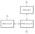
도 1은 종래 기술에 따른 안테나 시스템의 구성도이다.1 is a block diagram of an antenna system according to the prior art.
도 1을 참조하면, 종래 기술에 따른 안테나 시스템은 RFID 리더부(10), RFID 안테나부(20) 및 RFID 태그(30)를 포함한다.Referring to FIG. 1, an antenna system according to the related art includes an
상기 RFID 리더부(10)는 내장용 또는 외장용의 RFID 안테나부(20)를 포함한다. 상기 RFID 안테나부(20)는 액티브 신호(active signal)를 발산하여 전자기장으로서 RF 필드(RF field)를 형성한다.The
또한, 상기 RF 필드 내에 RFID 태그(30)가 진입하면, RFID 태그(30)는 RFID 리더부(10)의 안테나(20)에서 발산된 액티브 신호를 수신하고, 수신된 액티브 신호를 이용하여 RFID 태그 내에 저장되어 있는 정보를 RFID 안테나부(20)로 송신하게 된다. 이후, RFID 리더부(10)는 RFID 태그(30)에서 전송된 정보를 수신하고 이를 분석하여, RFID 태그(30)가 장착된 물건의 고유정보를 취득한다.In addition, when the
그러나, 이와 같은 안테나 시스템은 RFID 안테나부(20)에서 RFID 태그(30)로 액티브 신호를 발산해야만 상기 RFID 태그(30)가 응답하는 구조로 되어 있다.However, such an antenna system has a structure in which the
다시 말해서, 종래의 안테나 시스템은 RFID 리더부(10)에서 RFID 안테나부(20)로 직접 명령어를 송신하여, RFID 태그(30)를 웨이크-업(wake-up) 시킨 후 통신을 수행함으로써, 최초 통신 시간이 길어지고, 인식 속도가 느려지는 현상이 발생한다.In other words, the conventional antenna system transmits a command directly from the
본 발명에 따른 실시 예에서는 새로운 구조의 선반 안테나 시스템을 제공하도록 한다.Embodiments according to the present invention to provide a shelf antenna system of a new structure.
또한, 본 발명에 따른 실시 예에서는 샤워링 기능을 적용하여 태그의 인식률을 향상시킬 수 있는 선반 안테나 시스템을 제공하도록 한다.In addition, an embodiment according to the present invention is to provide a shelf antenna system that can improve the recognition rate of the tag by applying a shower function.
제안되는 실시 예에서 이루고자 하는 기술적 과제들은 이상에서 언급한 기술적 과제들로 제한되지 않으며, 언급되지 않은 또 다른 기술적 과제들은 아래의 기재로부터 제안되는 실시 예가 속하는 기술분야에서 통상의 지식을 가진 자에게 명확하게 이해될 수 있을 것이다.The technical problems to be achieved in the proposed embodiment are not limited to the technical problems mentioned above, and other technical problems not mentioned above are clear to those skilled in the art to which the proposed embodiments belong from the following description. Can be understood.
본 발명의 실시 예에 따른 선반 안테나 시스템은 제 1 제어신호에 의해 동작하는 제 1 안테나; 제 2 제어신호에 의해 동작하고, 접근한 물품에 부착된 RFID 태그로부터 물품 정보를 획득하여 전달하는 제 2 안테나; 및 상기 제 1 및 2 제어신호를 발생하고, 상기 제 2 안테나를 통해 획득된 물품 정보를 이용하여 상기 물품을 관리하는 리더부를 포함한다.Shelf antenna system according to an embodiment of the present invention includes a first antenna operating by a first control signal; A second antenna operated by a second control signal and configured to acquire and transmit article information from an RFID tag attached to an accessed article; And a reader unit generating the first and second control signals and managing the article by using the article information obtained through the second antenna.
또한, 본 발명의 실시 예에 따른 선반 안테나 시스템은 선반 케이스; 상기 선반 케이스의 적어도 하나의 제 1 면에 장착되며, 제 1 시점에 동작하는 제 1 안테나; 및 상기 선반 케이스의 제 2 면에 장착되며, 제 2 시점에 동작하는 제 2 안테나를 포함한다.In addition, the shelf antenna system according to an embodiment of the present invention; A first antenna mounted on at least one first surface of the shelf case and operating at a first time point; And a second antenna mounted on a second surface of the shelf case and operating at a second time point.
본 발명에 따른 실시 예에 의하면, 기존의 선반 안테나에 샤워링 기능을 추가함으로써, 태그의 인식률 및 인식 속도를 증가시켜 보다 안정된 선반 안테나 시스템을 구성할 수 있는 효과가 있다.According to an embodiment of the present invention, by adding a shower function to an existing shelf antenna, it is possible to configure a more stable shelf antenna system by increasing the recognition rate and recognition rate of the tag.
도 1은 종래 기술에 따른 안테나 시스템의 구성도이다.
도 2는 본 발명의 실시 예에 따른 선반 안테나 시스템의 구성도이다.
도 3은 RFID 리더부의 상세 구성도이다.
도 4는 본 발명의 다른 실시 예에 따른 선반 안테나 시스템의 구성도이다.
도 5는 본 발명의 실시 예에 따른 선반 안테나 시스템의 적용 예를 나타낸 도면이다.1 is a block diagram of an antenna system according to the prior art.
2 is a block diagram of a shelf antenna system according to an embodiment of the present invention.
3 is a detailed configuration diagram of the RFID reader unit.
4 is a block diagram of a shelf antenna system according to another embodiment of the present invention.
5 is a view showing an application example of a shelf antenna system according to an embodiment of the present invention.
이하, 첨부한 도면들을 참조하여, 본 발명의 바람직한 실시 예를 더욱 상세하게 설명하고자 한다. 본 발명을 설명함에 있어 전체적인 이해를 용이하게 하기 위하여 도면상의 동일한 구성요소에 대해서는 동일한 참조부호를 사용하고 동일한 구성요소에 대해서 중복된 설명은 생략한다.Hereinafter, with reference to the accompanying drawings, it will be described in detail a preferred embodiment of the present invention. In order to facilitate the understanding of the present invention, the same reference numerals are used for the same constituent elements in the drawings and redundant explanations for the same constituent elements are omitted.
도 2는 본 발명의 실시 예에 따른 선반 안테나 시스템의 구성도이다.2 is a block diagram of a shelf antenna system according to an embodiment of the present invention.
도 2를 참조하면, 선반 안테나 시스템은 RFID 리더부(110), 제 1 안테나(120) 및 제 2 안테나(130)를 포함한다.Referring to FIG. 2, the shelf antenna system includes an
이때, 상기 제 1 안테나(120)는 복수 개로 구성될 수 있으며, 이에 따라 제 1 안테나(120)는 제 1 안테나 #1(121), 제 1 안테나 #2(122), 제 1 안테나 #3(123) 및 제 4 안테나부 #4(124)를 포함할 수 있다.In this case, the
상기와 같은 선반 안테나 시스템은 선반 내로 진입한 물품의 식별정보를 획득하고, 상기 획득한 식별정보를 관리하거나, 이를 별도의 서버로 전송한다.The shelf antenna system as described above acquires the identification information of the article entered into the shelf, manages the obtained identification information, or transmits it to a separate server.
RFID 리더부(110)는 제 1 안테나(120) 및 제 2 안테나(130)의 동작을 제어한다.The
보다 구체적으로, RFID 리더부(110)는 제 1 제어신호를 발생하여, 상기 제 1 안테나(120)가 동작하도록 하거나, 제2 제어신호를 발생하여 상기 제 2 안테나(130)가 동작하도록 한다.More specifically, the
이때, 상기 제 1 제어신호는 상기 선반 안테나 시스템 근처에 진입한 물품에 부착된 RFID 태그를 깨우기 위한 Wake-Up 신호이고, 상기 제 2 제어신호는 상기 RFID 태그에 저장되어 있는 물품의 식별정보를 읽기 위산 Reading 신호이다.At this time, the first control signal is a wake-up signal for waking up the RFID tag attached to the article entered near the shelf antenna system, the second control signal is to read the identification information of the article stored in the RFID tag Gastric Reading is a signal.
이를 위해, 상기 RFID 리더부(110)는 상기 제 1 제어신호를 발생하여, 상기 제 1 안테나(120)를 동작시킴으로써, 상기 제 1 안테나(120)의 동작에 의해 선반 주위에 접근한 RFID 태그가 wake-up되도록 한다.To this end, the
또한, 상기 RFID 리더부(110)는 상기 제 2 제어신호를 발생하여 상기 제 2 안테나(130)를 동작시킴으로써, 상기 제 2 안테나(120)의 동작에 의해 주위에 접근한 RFID 태그로부터 물품 정보가 획득되도록 한다.In addition, the
도 3은 RFID 리더부(110)의 상세 구성도이다.3 is a detailed configuration diagram of the
도 3을 참조하면, RFID 리더부(110)는 통신부(111), 전원 공급부(112), RFID 모뎀(113) 및 제어부(114)를 포함한다.Referring to FIG. 3, the
통신부(111)는 별도의 컴퓨터(도시하지 않음)와 데이터 통신을 수행하여, 획득한 물품 정보를 상기 서버로 전달하거나, 상기 서버로부터 전달되는 각종 신호를 수신한다. 여기에서, 상기 수신되는 각종 신호에는 동작 개시 신호가 포함될 수 있다.The
상기 통신부(111)는 USB 통신 규격을 통해 상기 컴퓨터와 데이터 통신을 수행할 수 있다.The
전원 공급부(112)는 상기 통신부(111)를 통해 전달되는 전원을 RFID 모뎀(113)과 제어부(114)에 각각 전달한다. 즉, 상기 RFID 리더부(110)는 별도의 컴퓨터에 연결될 수 있으며, 그에 따라 상기 컴퓨터는 USB 인터페이스를 통해 상기 RFID 리더부(110)로 구동 전원을 공급할 수 있다.The
RFID 모뎀(113)은 제 1 안테나(120) 및 제 2 안테나(130)로 제어신호를 전송하거나, 상기 제 2 안테나(130)로부터 전달되는 물품 정보를 획득한다.The
제어부(114)는 RFID 리더부(110)의 전반적인 동작을 제어한다.The
즉, 상기 제어부(114)는 제 1 제어신호를 발생하여 상기 제 1 안테나(120)의 동작이 이루어지도록 한다.That is, the
이때, 상기 제어부(114)는 제 1 시점에 상기 제 1 제어신호를 발생하여 상기 제 1 안테나(120)의 동작을 제어할 수 있다. 상기 제 1 시점은 일정 시간 간격에 따른 일정 주기일 수 있다. 즉, 상기 일정 주기가 10초 간격인 경우, 상기 제 1 제어신호는 10초 간격으로 발생되며, 그에 따라 상기 제 1 안테나(120)는 10초 간격으로 동작하게 된다.In this case, the
또한, 상기 제 1 시점은 일정 주기가 아닌 모든 시점일 수 있다. 즉, 상기 제 1 제어신호는 항시 발생할 수 있으며, 이에 따라 상기 제 1 안테나(120)는 항상 동작을 수행할 수 있다.In addition, the first time point may be any time point that is not a predetermined period. That is, the first control signal may always occur, and accordingly, the
또한, 제어부(114)는 제 2 제어신호를 발생하여 상기 제 2 안테나(130)의 동작이 이루어지도록 한다.In addition, the
이때, 상기 제어부(114)는 제 2 시점에 상기 제 2 제어신호를 발생하여 상기 제 2 안테나(130)의 동작을 제어할 수 있다. 상기 제 2 시점은 상기 제 1 안테나(120)의 동작에 의해 wake-up된 RFID 태그가 감지된 시점일 수 있다.In this case, the
제 1 안테나(120)는 상기 RFID 리더부(110)를 통해 발생되는 제 1 제어신호에 의해 동작하며, 그에 따라 선반 주위에 접근하는 RFID 태그를 깨우기 위한 동작을 수행한다.The
즉, 상기 제 1 안테나(120)는 상기 RFID 태그를 부착한 물품이 진입하는 진입로에 설치될 수 있으며, 그에 따라 상기 진입로에 전자파를 발생시키는 샤워링 동작을 수행하여, 상기 발생되는 전자파에 의해 상기 물품에 부착된 RFID 태그가 wake-up되도록 한다.That is, the
제 2 안테나(130)는 상기 RFID 리더부(120)를 통해 발생되는 제 2 제어신호에 의해 동작하며, 그에 따라 상기 선반 주위에 접근하는 RFID 태그로부터 물품 정보를 획득한다.The
이때, 상기 제 2 안테나(130)에 의해 상기 RFID 태그로부터 물품 정보를 획득하기 위한 동작이 수행될 때, 상기 RFID 태그는 상기 제 1 안테나(120)의 동작에 의해 이미 Wake-up되어 있는 상태이므로, 상기 제 2 안테나(130)는 상기 RFID 태그로부터 단시간에 물품 정보를 획득할 수 있게 된다.In this case, when an operation for acquiring article information from the RFID tag is performed by the
즉, 본 발명에 따른 실시 예에서는 샤워링 기능을 이용하여 선반 내로 진입하는 RFID 태그를 미리 wake-up 시키고, 상기 wake-up된 RFID 태그의 접근이 감지됨에 따라 상기 RFID 태그로부터 물품 정보를 획득하기 때문에, 상기 RFID 태그를 wake-up시키기 위한 시간을 단축할 수 있어 태그 인식률을 향상시킬 수 있다.That is, in the embodiment according to the present invention, the wake-up RFID tag entering the shelf using the showering function is pre-wakeed, and the article information is obtained from the RFID tag as the access of the wake-up RFID tag is detected. Therefore, the time for wake-up of the RFID tag can be shortened and the tag recognition rate can be improved.
이때, 상기 제 1 안테나(120)는 RFID 태그를 부착한 물품의 접근이 전혀 없는 경우에도 계속적인 동작을 수행하고 있을 수 있다.In this case, the
이와 같은 경우, 불필요한 전력이 낭비될 수 있으며, 이에 따라 본 발명에 따른 실시 예에서는 경우에 따라 상기 제 1 안테나(120)를 구성하는 복수 개의 안테나 중 특정 안테나만을 선택적으로 동작시킨다.In such a case, unnecessary power may be wasted, and accordingly, according to an exemplary embodiment of the present invention, only a specific antenna of a plurality of antennas constituting the
이를 위해, 본 발명에 따른 실시 예에서는 도 4에서와 같이 스위칭부(140)를 포함할 수 있다.To this end, the embodiment according to the present invention may include a
상기 스위칭부(140)는 각 제 1 안테나 #1~#4(120)를 동작시키기 위한 제 1 제어신호를 선택적으로 차단할 수 있으며, 상기 각 제 1 안테나 #1~#4(120)에 공급되는 구동 전원을 차단할 수 있다.The
즉, RFID 리더부(110)는 RFID 태그의 접근이 일정 시간 동안 없으면, 상기 복수의 안테나 중 하나 또는 두 개의 제 1 안테나만 동작하도록 상기 각 제 1 안테나와 연결된 스위칭부(140)에 온/오프 신호를 전송한다.That is, the
그에 따라, 일정시간 동안 RFID 태그의 접근이 없으면, 상기 복수의 제 1 안테나 중 특정 제 1 안테나만이 동작할 수 있다. 이때, 상기 동작되는 제 1 안테나는 물품의 접근이 이루어지는 시작 지점, 다시 말해서 선반의 입구 쪽에 설치된 안테나임이 바람직하다.Accordingly, when there is no access of the RFID tag for a predetermined time, only a specific first antenna of the plurality of first antennas may operate. In this case, it is preferable that the operated first antenna is an antenna installed at a starting point where the article is accessed, that is, at the entrance of the shelf.
이후, 특정 RFID 태그의 접근이 인식되면, 상기 RFID 리더부(110)는 모든 제 1 안테나의 동작이 수행되도록 한다.Thereafter, when the access of the specific RFID tag is recognized, the
한편, 상기와 같은 선반 안테나 시스템 주위에 접근하는 RFID 태그는 동작 방법에 따라 능동형(Active) 태그와, 수동형(Passive) 태그를 포함한다.Meanwhile, the RFID tag approaching the shelf antenna system as described above includes an active tag and a passive tag according to an operation method.
상기 능동형 태그는 태그 내부 자체에 전원이 존재하며, 상기 존재하는 전원에 의해 동작한다.The active tag has a power source inside the tag itself and is operated by the existing power source.
반면, 상기 수동형 태그는 리더로부터의 자기 에너지를 받아 이를 전원으로 이용하여 동작하게 된다.On the other hand, the passive tag receives magnetic energy from the reader and operates by using it as a power source.
즉, 수동형 태그에서 사용되는 칩은 리더부로부터 반송파를 공급받아 이를 가지고 구동 전원을 생성하며, 상기 생성된 구동전원에 의해 리더와의 통신 동작을 수행하게 된다. 이를 위해, 상기 태그는 캐패시터를 포함하고 있으며, 상기 캐패시터의 충전 및 방전 동작에 의해 물품 정보를 리더로 전송하게 된다.That is, the chip used in the passive tag receives a carrier wave from the reader unit to generate driving power, and performs a communication operation with the reader by the generated driving power. To this end, the tag includes a capacitor, and the article information is transmitted to the reader by the charging and discharging operation of the capacitor.
이때, 상기와 같은 선반 안테나 시스템 주위에 접근한 태그가 상기 능동형 태그일 경우, 상기 제 1 안테나(120)에서 발생하는 전자파는 상기 접근하는 태그를 깨우기 위한 wake-up 신호일 수 있다.In this case, when the tag approached around the shelf antenna system is the active tag, the electromagnetic waves generated by the
그러나, 상기 선반 안테나 시스템 주위에 접근한 태그가 수동형 태그일 경우, 상기 제 1 안테나(120)에서 발생하는 전자파는 상기 수동형 태그 내부에 구비된 캐패시터를 충전시키기 위한 신호로서의 기능을 수행할 수 있다.However, when the tag approaching around the shelf antenna system is a passive tag, the electromagnetic waves generated by the
즉, 상기와 같은 수동형 태그는 상기 캐패시터의 충전 상태에 따라 반응속도가 결정될 수 있다. 다시 말해서, 상기 캐패시터의 충전 상태가 높은 경우에는 그만큼 반응 속도가 증가하게 되고, 상기 충전 상태가 낮은 경우에는 리더로부터 전송되는 신호에 의해 충전 동작을 수행해야함으로 인해 반응 속도가 감소하게 된다.That is, in the passive tag as described above, the reaction rate may be determined according to the state of charge of the capacitor. In other words, when the state of charge of the capacitor is high, the reaction rate increases accordingly, and when the state of charge is low, the reaction rate decreases due to the charging operation performed by a signal transmitted from the reader.
이에 따라, 상기 제 1 안테나(120)에서 발생하는 전자파는 주위에 접근한 수동형 태그 내부에 구비된 캐패시터를 충전시킴으로써, 상기 주위에 접근한 수동형 태그의 반응 속도를 증가시키며, 이로 인해 태그 인식률을 증가시킬 수 있도록 한다.Accordingly, the electromagnetic wave generated by the
도 5는 본 발명의 실시 예에 따른 선반 안테나 시스템의 적용 예를 나타낸 도면이다.5 is a view showing an application example of a shelf antenna system according to an embodiment of the present invention.
도 5를 참조하면, 선반 안테나 시스템은 선반 케이스(200)와, 상기 선반 케이스(200)의 적어도 제 1 면에 장착된 제 1 안테나(120) 및 상기 선반 케이스(200)의 제 2 면에 장착된 제 2 안테나(130)를 포함한다.Referring to FIG. 5, the shelf antenna system is mounted on a
상기 선반 케이스(200)는 RFID 태그를 부착한 물품의 진입을 위한 공간을 제공한다. 즉, 상기 선반 케이스(200)는 RFID 태그를 인식할 수 있는 영역을 제공하여, 상기 선반 케이스(200)에 의해 제공된 영역으로 상기 RFID 태그를 부착한 물품이 접근될 수 있도록 한다.The
또한, 선반 케이스(200)는 상기 제 1 안테나(120) 및 제 2 안테나(130)가 설치 및 고정되는 설치 공간을 제공한다.In addition, the
이때, 상기 선반 케이스(200)는 제 1면, 제 2면, 제3면 및 제 4면을 포함할 수 있다. 그러나, 도 5에 도시된 선반 케이스(200)의 형상은 본 발명의 일 실시 예에 불과할 뿐, 상기 선반 케이스(200)가 별도의 제 5 면 및 6면을 포함할 수도 있을 것이다.In this case, the
제 1 안테나(120)는 상기 선반 케이스의 적어도 한 면에 장착된다.The
제 2 안테나(120)는 상기 선반 케이스의 특정 제 2면에 장착된다.The
다시 말해서, 상기 제 2 안테나(120)는 상기 선반 케이스(200)의 하면에 장착되어, 상기 선반 케이스 내부로 진입한 물품으로부터 RFID 태그 정보를 용이하게 획득할 수 있도록 한다.In other words, the
또한, 제 1 안테나(120)는 사방을 통해 상기 선반 케이스(200) 내부로 진입하는 RFID 태그를 wake-up시키기 위해, 상기 선반 케이스(200)의 좌측면, 우측면 및 후면에 각각 복수 개 설치될 수 있다.In addition, a plurality of
또한, 상기 RFID 태그의 진입이 가장 많이 이루어진 방향을 이용하여, 특정 시점에는 상기 방향에 대응되는 면에 장착된 제 1 안테나(120)만을 동작시키고, 추후 다른 방향에 대응되는 면에 장착된 나머지 제 1 안테나(120)도 동작시킬 수 있을 것이다.In addition, by using the direction in which the most entry of the RFID tag is made, only the
상기와 같이 본 발명에 따른 실시 예에 의하면, 기존의 선반 안테나에 샤워링 기능을 추가함으로써, 태그의 인식률 및 인식 속도를 증가시켜 보다 안정된 선반 안테나 시스템을 구성할 수 있는 효과가 있다.According to the embodiment of the present invention as described above, by adding a shower function to the existing shelf antenna, it is possible to increase the recognition rate and recognition speed of the tag to configure a more stable shelf antenna system.
이상에서 본 발명에 대하여 그 바람직한 실시 예를 중심으로 설명하였으나 이는 단지 예시일 뿐 본 발명을 한정하는 것이 아니며, 본 발명이 속하는 분야의 통상의 지식을 가진 자라면 본 발명의 본질적인 특성을 벗어나지 않는 범위에서 이상에 예시되지 않은 여러 가지의 변형과 응용이 가능함을 알 수 있을 것이다. 예를 들어, 본 발명의 실시 예에 구체적으로 나타난 각 구성 요소는 변형하여 실시할 수 있는 것이다. 그리고 이러한 변형과 응용에 관계된 차이점들은 첨부된 청구 범위에서 규정하는 본 발명의 범위에 포함되는 것으로 해석되어야 할 것이다.While the present invention has been particularly shown and described with reference to exemplary embodiments thereof, it is to be understood that the invention is not limited to the disclosed exemplary embodiments, but, on the contrary, It will be understood that various modifications and applications other than those described above are possible. For example, each component shown in detail in the embodiment of the present invention may be modified. It is to be understood that all changes and modifications that come within the meaning and range of equivalency of the claims are therefore intended to be embraced therein.
110: RFID 리더부
120: 제 1 안테나
130: 제 2 안테나110: RFID reader
120: first antenna
130: second antenna
Claims (12)
Translated fromKorean제 1 제어신호에 의해 동작하여, 주위에 접근한 RFID 태그를 wake-up 시키는 제 1 안테나;
제 2 제어신호에 의해 동작하여, 상기 제 1 안테나에 의해 wake-up 된 RFID 태그로부터 물품 정보를 획득하여 전달하는 제 2 안테나; 및
상기 제 1 및 2 제어신호를 발생하고, 상기 제 2 안테나를 통해 획득된 물품 정보를 이용하여 상기 물품을 관리하는 리더부를 포함하는 안테나 시스템.An antenna system for obtaining article information from an RFID tag,
A first antenna operated by the first control signal to wake-up an RFID tag near the periphery;
A second antenna operated by a second control signal to acquire and transmit article information from an RFID tag waked up by the first antenna; And
And a reader unit for generating the first and second control signals and managing the article by using the article information obtained through the second antenna.
상기 제 1 안테나는 상기 제 1 제어신호에 따라 전자파를 발생시키는 안테나 시스템.The method of claim 1,
And the first antenna generates electromagnetic waves in accordance with the first control signal.
상기 제 1 안테나는 제 2 안테나를 통해 형성되는 모든 태그 감지 영역에 상기 전자파를 발생시키기 위해 복수 개 배치되는 안테나 시스템.The method of claim 2,
And a plurality of first antennas are arranged to generate the electromagnetic waves in all tag detection regions formed through the second antennas.
상기 복수 개 배치된 제 1 안테나의 동작 상태를 스위칭하는 스위칭부가 더 포함되는 안테나 시스템.The method of claim 3,
The antenna system further comprises a switching unit for switching the operating state of the plurality of first antennas arranged.
상기 제 1 제어신호는 상기 RFID 태그를 깨우기 위한 wake-up 신호이고,
상기 제 2 제어신호는 상기 물품 정보를 읽기 위한 reading 신호인 것을 특징으로 하는 안테나 시스템.The method of claim 1,
The first control signal is a wake-up signal for waking up the RFID tag,
And the second control signal is a reading signal for reading the article information.
상기 RFID 태그는 물품 정보 전송 동작을 위해 충전 및 방전 동작을 수행하는 캐패시터가 더 포함되며,
상기 제 1 제어신호는 상기 RFID 태그에 포힘된 캐패시터를 충전시키기 위한 신호인 것을 특징으로 하는 안테나 시스템.6. The method of claim 5,
The RFID tag further includes a capacitor performing a charging and discharging operation for the article information transmission operation,
And the first control signal is a signal for charging a capacitor foamed in the RFID tag.
상기 제 2 안테나는 UHF 대역의 안테나인 것을 특징으로 하는 안테나 시스템.The method of claim 1,
And the second antenna is an antenna of a UHF band.
상기 선반 케이스의 적어도 하나의 제 1 면에 장착되며, 제 1 시점에 동작하여 상기 선반 케이스 주위에 접근한 RFID 태그를 wake-up 시키는 제 1 안테나; 및
상기 선반 케이스의 제 2 면에 장착되며, 제 2 시점에 동작하여 상기 제 1 안테나에 의해 wake-up된 RFID 태그로부터 정보를 획득하는 제 2 안테나를 포함하는 선반 안테나 시스템.Shelf case;
A first antenna mounted on at least one first surface of the shelf case and operating at a first time point to wake-up an RFID tag approaching around the shelf case; And
And a second antenna mounted on a second surface of the shelf case and operating at a second time point to obtain information from an RFID tag waked up by the first antenna.
상기 제 1 면은 상기 선반 케이스의 후면, 좌측면 및 우측면 중 적어도 어느 하나를 포함하며,
상기 제 2 면은 상기 선반 케이스의 하면인 것을 특징으로 하는 선반 안테나 시스템.The method of claim 8,
The first side includes at least one of a rear side, a left side, and a right side of the shelf case,
The second surface is a shelf antenna system, characterized in that the lower surface of the shelf case.
상기 제 1 안테나는 복수의 방향으로 전자파를 발생시키기 위해 상기 선반 케이스의 후면, 좌측면 및 우측면 중 적어도 둘 이상의 면에 장착되는 선반 안테나 시스템.The method of claim 9,
The first antenna is a shelf antenna system mounted on at least two or more of the rear, left and right sides of the shelf case to generate electromagnetic waves in a plurality of directions.
상기 제 1 시점은 특정 시간 간격의 일정 주기이며,
상기 제 2 시점은 태그가 부착된 물품의 접근 시점인 것을 특징으로 하는 선반 안테나 시스템.The method of claim 8,
The first time point is a constant period of a specific time interval,
The second time point is a shelf antenna system, characterized in that the access point of the tagged article.
상기 제 1 안테나는
상기 RFID 태그에 내장된 캐패시터를 충전시키는 선반 안테나 시스템.The method of claim 8,
The first antenna
Shelf antenna system for charging the capacitor embedded in the RFID tag.
Priority Applications (5)
| Application Number | Priority Date | Filing Date | Title |
|---|---|---|---|
| KR1020110067788AKR101216841B1 (en) | 2011-07-08 | 2011-07-08 | Shelf-shaped rfid system |
| US13/542,536US20130009755A1 (en) | 2011-07-08 | 2012-07-05 | Rfid antenna system and method for controlling the same |
| EP12175277AEP2544123A2 (en) | 2011-07-08 | 2012-07-06 | RFID antenna system and method for controlling the same |
| JP2012152767AJP2013020618A (en) | 2011-07-08 | 2012-07-06 | Antenna system and method for controlling the same |
| CN201210235348XACN102999740A (en) | 2011-07-08 | 2012-07-06 | RFID antenna system and method for controlling the same |
Applications Claiming Priority (1)
| Application Number | Priority Date | Filing Date | Title |
|---|---|---|---|
| KR1020110067788AKR101216841B1 (en) | 2011-07-08 | 2011-07-08 | Shelf-shaped rfid system |
Publications (1)
| Publication Number | Publication Date |
|---|---|
| KR101216841B1true KR101216841B1 (en) | 2012-12-28 |
Family
ID=46507897
Family Applications (1)
| Application Number | Title | Priority Date | Filing Date |
|---|---|---|---|
| KR1020110067788AExpired - Fee RelatedKR101216841B1 (en) | 2011-07-08 | 2011-07-08 | Shelf-shaped rfid system |
Country Status (5)
| Country | Link |
|---|---|
| US (1) | US20130009755A1 (en) |
| EP (1) | EP2544123A2 (en) |
| JP (1) | JP2013020618A (en) |
| KR (1) | KR101216841B1 (en) |
| CN (1) | CN102999740A (en) |
Cited By (1)
| Publication number | Priority date | Publication date | Assignee | Title |
|---|---|---|---|---|
| KR101546469B1 (en)* | 2014-01-14 | 2015-08-21 | 케이아이씨시스템즈(주) | RFID tag for rail vehicle and method of using RFID system having the same |
Families Citing this family (10)
| Publication number | Priority date | Publication date | Assignee | Title |
|---|---|---|---|---|
| KR20120057835A (en)* | 2010-11-29 | 2012-06-07 | 한국전자통신연구원 | Apparatus of RFID electronic shelf and method of detecting the location of the tag using the same |
| CN104077551B (en)* | 2013-03-29 | 2017-10-24 | 西门子公司 | A kind of recognition methods of RFID tag, device and system |
| US9830791B2 (en)* | 2015-05-27 | 2017-11-28 | Tyco Fire & Security Gmbh | Self-detachable RFID tags |
| CN105260690B (en)* | 2015-11-09 | 2018-02-23 | 深圳市鸿陆技术有限公司 | RFID reader multiple antennas identifies the method and system of electronic tag |
| CN106971218B (en)* | 2017-03-31 | 2020-07-28 | 深圳市阿尔艾富信息技术股份有限公司 | An RFID electronic tag |
| CN107331050B (en)* | 2017-07-04 | 2019-10-11 | 深圳正品创想科技有限公司 | Goods checking method and its system |
| CN108734040B (en)* | 2018-05-22 | 2021-07-13 | 苏州大学 | Passive RFID tag rapid detection equipment |
| EP3945449A1 (en)* | 2020-07-27 | 2022-02-02 | Nxp B.V. | Rfid transponder having modifiable settings |
| FR3114900B1 (en)* | 2020-10-06 | 2023-11-03 | Banks And Acquirers Int Holding | Electronic payment terminal and method for detecting a corresponding payment method. |
| CN117952141B (en)* | 2024-03-26 | 2024-07-23 | 四川凯路威科技有限公司 | Carrier-powered RFID tag circuit and data transceiving method |
Family Cites Families (9)
| Publication number | Priority date | Publication date | Assignee | Title |
|---|---|---|---|---|
| JP3596359B2 (en)* | 1999-07-12 | 2004-12-02 | 松下電器産業株式会社 | Mobile object identification device and mobile object identification system |
| JP2001273467A (en)* | 2000-03-24 | 2001-10-05 | Toshiba Corp | Wireless information processor |
| KR20040096522A (en)* | 2002-01-09 | 2004-11-16 | 미드웨스트바코 코포레이션 | Intelligent station using multiple rf antennae and inventory control system and method incorporating same |
| US6903656B1 (en)* | 2003-05-27 | 2005-06-07 | Applied Wireless Identifications Group, Inc. | RFID reader with multiple antenna selection and automated antenna matching |
| US7792711B2 (en)* | 2004-02-03 | 2010-09-07 | Rtc Industries, Inc. | System for inventory management |
| WO2007131839A1 (en)* | 2006-05-15 | 2007-11-22 | International Business Machines Corporation | METHOD AND SYSTEMS FOR LOCALIZING OBJECTS USING PASSIVE RFID TAGs |
| US7516890B1 (en)* | 2006-05-25 | 2009-04-14 | The United States Of America As Represented By The Administrator Of The National Aeronautics And Space Administration | Interactive inventory monitoring |
| US20100148965A1 (en)* | 2008-12-16 | 2010-06-17 | Sensormatic Electronics Corporation | Method and system for item level uhf rfid tag with low frequency power assist |
| KR101305860B1 (en)* | 2009-03-10 | 2013-09-06 | 엘에스산전 주식회사 | Rfid antenna system and control method of the same |
- 2011
- 2011-07-08KRKR1020110067788Apatent/KR101216841B1/ennot_activeExpired - Fee Related
- 2012
- 2012-07-05USUS13/542,536patent/US20130009755A1/ennot_activeAbandoned
- 2012-07-06JPJP2012152767Apatent/JP2013020618A/enactivePending
- 2012-07-06CNCN201210235348XApatent/CN102999740A/enactivePending
- 2012-07-06EPEP12175277Apatent/EP2544123A2/ennot_activeWithdrawn
Cited By (1)
| Publication number | Priority date | Publication date | Assignee | Title |
|---|---|---|---|---|
| KR101546469B1 (en)* | 2014-01-14 | 2015-08-21 | 케이아이씨시스템즈(주) | RFID tag for rail vehicle and method of using RFID system having the same |
Also Published As
| Publication number | Publication date |
|---|---|
| JP2013020618A (en) | 2013-01-31 |
| US20130009755A1 (en) | 2013-01-10 |
| CN102999740A (en) | 2013-03-27 |
| EP2544123A2 (en) | 2013-01-09 |
Similar Documents
| Publication | Publication Date | Title |
|---|---|---|
| KR101216841B1 (en) | Shelf-shaped rfid system | |
| CN104361388B (en) | A UHF wireless sensor tag | |
| CN201057561Y (en) | Fixed radio frequency reader-writer | |
| US20110248833A1 (en) | Rfid system | |
| CN103839092B (en) | A kind of ultrahigh frequency radio frequency identification (RFID) reader | |
| CN110972242A (en) | Narrow-band Internet of things communication system based on honeycomb | |
| US20190212433A1 (en) | Position-Sensing Sensor and Position-Sensing System | |
| CN105590078A (en) | Equipment automatic identification apparatus and method based on RFID | |
| CN202548870U (en) | RFID system | |
| CN104700136B (en) | Article stowed location automatic station-keeping system and method | |
| KR100730745B1 (en) | Radio Frequency Recognition System and Control Method | |
| KR101001681B1 (en) | Active RFI system and its tag wake up control method | |
| US20070296582A1 (en) | Coordination of multiple integrated circuit assemblies of a device | |
| CN103679229A (en) | RFID system applied to library | |
| US10102405B2 (en) | Electromagnetic coupling reader | |
| CN102542305B (en) | Controlling method enabling an RFID (radio frequency identification device) reader-writer to realize environment-friendly reading and writing | |
| JP6313543B2 (en) | RFID tag and article management system using the same | |
| TWI289796B (en) | Radio frequency identification system | |
| KR20130039158A (en) | Radio frequency identification tag | |
| CN111667036A (en) | Method for remotely wirelessly charging electronic tag in air, charging system and electronic tag | |
| JP4037421B2 (en) | Tag system, IC tag, IC tag control method, program | |
| KR101809755B1 (en) | Radio Frequency Identification System | |
| KR101210600B1 (en) | Apparatus and method for identifying structure | |
| CN102064847A (en) | Intelligent target tracking system | |
| KR102039043B1 (en) | Active rfid tag for usn and controlling method thereof |
Legal Events
| Date | Code | Title | Description |
|---|---|---|---|
| A201 | Request for examination | ||
| PA0109 | Patent application | St.27 status event code:A-0-1-A10-A12-nap-PA0109 | |
| PA0201 | Request for examination | St.27 status event code:A-1-2-D10-D11-exm-PA0201 | |
| R18-X000 | Changes to party contact information recorded | St.27 status event code:A-3-3-R10-R18-oth-X000 | |
| D13-X000 | Search requested | St.27 status event code:A-1-2-D10-D13-srh-X000 | |
| D14-X000 | Search report completed | St.27 status event code:A-1-2-D10-D14-srh-X000 | |
| E902 | Notification of reason for refusal | ||
| PE0902 | Notice of grounds for rejection | St.27 status event code:A-1-2-D10-D21-exm-PE0902 | |
| R17-X000 | Change to representative recorded | St.27 status event code:A-3-3-R10-R17-oth-X000 | |
| P11-X000 | Amendment of application requested | St.27 status event code:A-2-2-P10-P11-nap-X000 | |
| P13-X000 | Application amended | St.27 status event code:A-2-2-P10-P13-nap-X000 | |
| E701 | Decision to grant or registration of patent right | ||
| PE0701 | Decision of registration | St.27 status event code:A-1-2-D10-D22-exm-PE0701 | |
| GRNT | Written decision to grant | ||
| PN2301 | Change of applicant | St.27 status event code:A-5-5-R10-R13-asn-PN2301 St.27 status event code:A-5-5-R10-R11-asn-PN2301 | |
| PR0701 | Registration of establishment | St.27 status event code:A-2-4-F10-F11-exm-PR0701 | |
| PR1002 | Payment of registration fee | St.27 status event code:A-2-2-U10-U11-oth-PR1002 Fee payment year number:1 | |
| PG1601 | Publication of registration | St.27 status event code:A-4-4-Q10-Q13-nap-PG1601 | |
| PN2301 | Change of applicant | St.27 status event code:A-5-5-R10-R11-asn-PN2301 | |
| PN2301 | Change of applicant | St.27 status event code:A-5-5-R10-R14-asn-PN2301 | |
| R18-X000 | Changes to party contact information recorded | St.27 status event code:A-5-5-R10-R18-oth-X000 | |
| R18-X000 | Changes to party contact information recorded | St.27 status event code:A-5-5-R10-R18-oth-X000 | |
| FPAY | Annual fee payment | Payment date:20151218 Year of fee payment:4 | |
| PR1001 | Payment of annual fee | St.27 status event code:A-4-4-U10-U11-oth-PR1001 Fee payment year number:4 | |
| FPAY | Annual fee payment | Payment date:20161219 Year of fee payment:5 | |
| PR1001 | Payment of annual fee | St.27 status event code:A-4-4-U10-U11-oth-PR1001 Fee payment year number:5 | |
| FPAY | Annual fee payment | Payment date:20171128 Year of fee payment:6 | |
| PR1001 | Payment of annual fee | St.27 status event code:A-4-4-U10-U11-oth-PR1001 Fee payment year number:6 | |
| FPAY | Annual fee payment | Payment date:20181126 Year of fee payment:7 | |
| PR1001 | Payment of annual fee | St.27 status event code:A-4-4-U10-U11-oth-PR1001 Fee payment year number:7 | |
| FPAY | Annual fee payment | Payment date:20191128 Year of fee payment:8 | |
| PR1001 | Payment of annual fee | St.27 status event code:A-4-4-U10-U11-oth-PR1001 Fee payment year number:8 | |
| PN2301 | Change of applicant | St.27 status event code:A-5-5-R10-R13-asn-PN2301 St.27 status event code:A-5-5-R10-R11-asn-PN2301 | |
| PC1903 | Unpaid annual fee | St.27 status event code:A-4-4-U10-U13-oth-PC1903 Not in force date:20201222 Payment event data comment text:Termination Category : DEFAULT_OF_REGISTRATION_FEE | |
| PC1903 | Unpaid annual fee | St.27 status event code:N-4-6-H10-H13-oth-PC1903 Ip right cessation event data comment text:Termination Category : DEFAULT_OF_REGISTRATION_FEE Not in force date:20201222 | |
| PN2301 | Change of applicant | St.27 status event code:A-5-5-R10-R13-asn-PN2301 St.27 status event code:A-5-5-R10-R11-asn-PN2301 | |
| R18-X000 | Changes to party contact information recorded | St.27 status event code:A-5-5-R10-R18-oth-X000 |