KR101216657B1 - Method of determining temperature of molten pig iron and method of operating blast furnace using same - Google Patents
Method of determining temperature of molten pig iron and method of operating blast furnace using sameDownload PDFInfo
- Publication number
- KR101216657B1 KR101216657B1KR1020117008945AKR20117008945AKR101216657B1KR 101216657 B1KR101216657 B1KR 101216657B1KR 1020117008945 AKR1020117008945 AKR 1020117008945AKR 20117008945 AKR20117008945 AKR 20117008945AKR 101216657 B1KR101216657 B1KR 101216657B1
- Authority
- KR
- South Korea
- Prior art keywords
- molten iron
- temperature
- blast furnace
- time
- seconds
- Prior art date
- Legal status (The legal status is an assumption and is not a legal conclusion. Google has not performed a legal analysis and makes no representation as to the accuracy of the status listed.)
- Active
Links
- 238000000034methodMethods0.000titleclaimsabstractdescription58
- 229910000805Pig ironInorganic materials0.000title1
- XEEYBQQBJWHFJM-UHFFFAOYSA-NIronChemical compound[Fe]XEEYBQQBJWHFJM-UHFFFAOYSA-N0.000claimsabstractdescription488
- 229910052742ironInorganic materials0.000claimsabstractdescription244
- 230000002159abnormal effectEffects0.000claimsdescription24
- 238000007664blowingMethods0.000claimsdescription13
- 238000009529body temperature measurementMethods0.000claimsdescription12
- 239000000571cokeSubstances0.000claimsdescription5
- 238000001514detection methodMethods0.000claimsdescription4
- 239000003245coalSubstances0.000claimsdescription3
- 239000002994raw materialSubstances0.000claimsdescription3
- 238000011017operating methodMethods0.000claimsdescription2
- 239000000155meltSubstances0.000claims1
- 239000002184metalSubstances0.000abstractdescription5
- 229910052751metalInorganic materials0.000abstractdescription5
- 235000019557luminanceNutrition0.000description37
- 238000005259measurementMethods0.000description30
- 239000002893slagSubstances0.000description26
- OKTJSMMVPCPJKN-UHFFFAOYSA-NCarbonChemical compound[C]OKTJSMMVPCPJKN-UHFFFAOYSA-N0.000description16
- 229910002804graphiteInorganic materials0.000description15
- 239000010439graphiteSubstances0.000description15
- 238000003384imaging methodMethods0.000description13
- 230000008859changeEffects0.000description12
- 230000005855radiationEffects0.000description9
- 238000010079rubber tappingMethods0.000description9
- 238000012545processingMethods0.000description8
- 238000006243chemical reactionMethods0.000description5
- 238000007654immersionMethods0.000description5
- 238000004364calculation methodMethods0.000description4
- 230000000052comparative effectEffects0.000description4
- 239000013307optical fiberSubstances0.000description4
- XLYOFNOQVPJJNP-UHFFFAOYSA-NwaterSubstancesOXLYOFNOQVPJJNP-UHFFFAOYSA-N0.000description4
- 241001270131Agaricus moelleriSpecies0.000description3
- 238000010586diagramMethods0.000description3
- 230000005856abnormalityEffects0.000description2
- 230000036760body temperatureEffects0.000description2
- 238000001816coolingMethods0.000description2
- 238000009826distributionMethods0.000description2
- 238000002844meltingMethods0.000description2
- 230000008018meltingEffects0.000description2
- 239000000203mixtureSubstances0.000description2
- 238000012986modificationMethods0.000description2
- 230000004048modificationEffects0.000description2
- 230000035699permeabilityEffects0.000description2
- 239000000523sampleSubstances0.000description2
- 206010027146MelanodermaDiseases0.000description1
- 229910000831SteelInorganic materials0.000description1
- 229910052799carbonInorganic materials0.000description1
- 238000002485combustion reactionMethods0.000description1
- 238000007796conventional methodMethods0.000description1
- 230000002950deficientEffects0.000description1
- 230000002349favourable effectEffects0.000description1
- 239000012530fluidSubstances0.000description1
- 238000005194fractionationMethods0.000description1
- 238000010438heat treatmentMethods0.000description1
- 238000009434installationMethods0.000description1
- 238000011835investigationMethods0.000description1
- 238000004519manufacturing processMethods0.000description1
- 230000007246mechanismEffects0.000description1
- 230000010287polarizationEffects0.000description1
- 239000010970precious metalSubstances0.000description1
- 230000008569processEffects0.000description1
- 230000000630rising effectEffects0.000description1
- 238000000926separation methodMethods0.000description1
- 239000007858starting materialSubstances0.000description1
- 239000010959steelSubstances0.000description1
- 238000003860storageMethods0.000description1
- 230000007704transitionEffects0.000description1
Images


Classifications
- C—CHEMISTRY; METALLURGY
- C21—METALLURGY OF IRON
- C21B—MANUFACTURE OF IRON OR STEEL
- C21B7/00—Blast furnaces
- C21B7/24—Test rods or other checking devices
- G—PHYSICS
- G01—MEASURING; TESTING
- G01J—MEASUREMENT OF INTENSITY, VELOCITY, SPECTRAL CONTENT, POLARISATION, PHASE OR PULSE CHARACTERISTICS OF INFRARED, VISIBLE OR ULTRAVIOLET LIGHT; COLORIMETRY; RADIATION PYROMETRY
- G01J5/00—Radiation pyrometry, e.g. infrared or optical thermometry
- G01J5/0022—Radiation pyrometry, e.g. infrared or optical thermometry for sensing the radiation of moving bodies
- C—CHEMISTRY; METALLURGY
- C21—METALLURGY OF IRON
- C21B—MANUFACTURE OF IRON OR STEEL
- C21B5/00—Making pig-iron in the blast furnace
- C—CHEMISTRY; METALLURGY
- C21—METALLURGY OF IRON
- C21B—MANUFACTURE OF IRON OR STEEL
- C21B5/00—Making pig-iron in the blast furnace
- C21B5/006—Automatically controlling the process
- C—CHEMISTRY; METALLURGY
- C21—METALLURGY OF IRON
- C21B—MANUFACTURE OF IRON OR STEEL
- C21B7/00—Blast furnaces
- C21B7/14—Discharging devices, e.g. for slag
- F—MECHANICAL ENGINEERING; LIGHTING; HEATING; WEAPONS; BLASTING
- F27—FURNACES; KILNS; OVENS; RETORTS
- F27B—FURNACES, KILNS, OVENS OR RETORTS IN GENERAL; OPEN SINTERING OR LIKE APPARATUS
- F27B1/00—Shaft or like vertical or substantially vertical furnaces
- F27B1/10—Details, accessories or equipment specially adapted for furnaces of these types
- F27B1/21—Arrangements of devices for discharging
- F—MECHANICAL ENGINEERING; LIGHTING; HEATING; WEAPONS; BLASTING
- F27—FURNACES; KILNS; OVENS; RETORTS
- F27B—FURNACES, KILNS, OVENS OR RETORTS IN GENERAL; OPEN SINTERING OR LIKE APPARATUS
- F27B1/00—Shaft or like vertical or substantially vertical furnaces
- F27B1/10—Details, accessories or equipment specially adapted for furnaces of these types
- F27B1/28—Arrangements of monitoring devices, of indicators, of alarm devices
- F—MECHANICAL ENGINEERING; LIGHTING; HEATING; WEAPONS; BLASTING
- F27—FURNACES; KILNS; OVENS; RETORTS
- F27D—DETAILS OR ACCESSORIES OF FURNACES, KILNS, OVENS OR RETORTS, IN SO FAR AS THEY ARE OF KINDS OCCURRING IN MORE THAN ONE KIND OF FURNACE
- F27D19/00—Arrangements of controlling devices
- F—MECHANICAL ENGINEERING; LIGHTING; HEATING; WEAPONS; BLASTING
- F27—FURNACES; KILNS; OVENS; RETORTS
- F27D—DETAILS OR ACCESSORIES OF FURNACES, KILNS, OVENS OR RETORTS, IN SO FAR AS THEY ARE OF KINDS OCCURRING IN MORE THAN ONE KIND OF FURNACE
- F27D21/00—Arrangement of monitoring devices; Arrangement of safety devices
- F27D21/0014—Devices for monitoring temperature
- G—PHYSICS
- G01—MEASURING; TESTING
- G01J—MEASUREMENT OF INTENSITY, VELOCITY, SPECTRAL CONTENT, POLARISATION, PHASE OR PULSE CHARACTERISTICS OF INFRARED, VISIBLE OR ULTRAVIOLET LIGHT; COLORIMETRY; RADIATION PYROMETRY
- G01J5/00—Radiation pyrometry, e.g. infrared or optical thermometry
- G—PHYSICS
- G01—MEASURING; TESTING
- G01J—MEASUREMENT OF INTENSITY, VELOCITY, SPECTRAL CONTENT, POLARISATION, PHASE OR PULSE CHARACTERISTICS OF INFRARED, VISIBLE OR ULTRAVIOLET LIGHT; COLORIMETRY; RADIATION PYROMETRY
- G01J5/00—Radiation pyrometry, e.g. infrared or optical thermometry
- G01J5/0037—Radiation pyrometry, e.g. infrared or optical thermometry for sensing the heat emitted by liquids
- G01J5/004—Radiation pyrometry, e.g. infrared or optical thermometry for sensing the heat emitted by liquids by molten metals
- C—CHEMISTRY; METALLURGY
- C21—METALLURGY OF IRON
- C21B—MANUFACTURE OF IRON OR STEEL
- C21B2300/00—Process aspects
- C21B2300/04—Modeling of the process, e.g. for control purposes; CII
- G—PHYSICS
- G01—MEASURING; TESTING
- G01J—MEASUREMENT OF INTENSITY, VELOCITY, SPECTRAL CONTENT, POLARISATION, PHASE OR PULSE CHARACTERISTICS OF INFRARED, VISIBLE OR ULTRAVIOLET LIGHT; COLORIMETRY; RADIATION PYROMETRY
- G01J5/00—Radiation pyrometry, e.g. infrared or optical thermometry
- G01J2005/0077—Imaging
Landscapes
- Engineering & Computer Science (AREA)
- Chemical & Material Sciences (AREA)
- Metallurgy (AREA)
- Manufacturing & Machinery (AREA)
- General Engineering & Computer Science (AREA)
- Materials Engineering (AREA)
- Mechanical Engineering (AREA)
- Organic Chemistry (AREA)
- Physics & Mathematics (AREA)
- General Physics & Mathematics (AREA)
- Spectroscopy & Molecular Physics (AREA)
- Radiation Pyrometers (AREA)
- Manufacture Of Iron (AREA)
- Blast Furnaces (AREA)
Abstract
Translated fromKoreanDescription
Translated fromKorean본 발명은 고로의 출선구로부터 유출되는 용선의 온도를 검지하는 방법에 관한 것이다.The present invention relates to a method for detecting the temperature of the molten iron flowing out from the outlet of the blast furnace.
고로 조업에 있어서, 용선의 온도는 고로 노 내의 열 상황을 판단하는 데 있어서 중요한 지표 중 하나이다. 출선 온도가 변동하는 경우에는 고로 노 내의 열 분포가 불균일한 것 등을 생각할 수 있는데, 이는 고로의 조업상 바람직하지 않다.In blast furnace operation, the temperature of the molten iron is one of the important indicators in determining the thermal situation in the blast furnace furnace. When the starting temperature fluctuates, it may be considered that the heat distribution in the blast furnace furnace is uneven, which is not preferable in the operation of the blast furnace.
그 때문에, 용선의 온도를 이하의 방법에 의하여 측정하였다.Therefore, the temperature of molten iron | metal was measured by the following method.
스키머에서 침지 소모형 열전대로 간헐적으로 온도를 측정하는 것이 일반적으로 행해지고 있는 방법이다. 구체적으로는, 출선통의 도중에 있는 스키머라고 하는 용선 슬래그 분리 장치로, 일회용 형태의 열전대 프로브를 용선에 침지하여 온도를 측정하는 방법이다.Intermittent measurement of temperature with an immersion consuming thermocouple in a skimmer is a common practice. Specifically, a molten iron slag separation device called a skimmer in the middle of the drawer is a method of measuring a temperature by immersing a disposable thermocouple probe in molten iron.
특허문헌 1과 2에는 출선통에서 방사 측온을 실시하는 방법이 개시되어 있다. 구체적으로는, 상기 침지 소모형 열전대 대신에, 비접촉으로 연속 측정 가능한 방사 온도계를 사용하여, 용선 온도를 구하는 방법으로서, 측정 신호의 시계열 데이터로부터 용선 상에 부유하는 슬래그나 카본 등에 의한 온도 측정의 오차를 측정 데이터의 불량으로서 배제하여 처리하는 방법이다.
특허문헌 3에는 출선구로부터 분출하는 용선에 광섬유를 침지하여 방사 측온을 실시하는 방법이 개시되어 있다. 구체적으로는, 광섬유 방사 온도계에 접속된 소모형 금속관 피복 광섬유를 용선 분류 중에 보내어 용선 내부에서 열 방사를 직접 수광하여 온도를 측정하는 방법이다.Patent Literature 3 discloses a method of performing radiation measurement by immersing an optical fiber in a molten iron sprayed from a tap hole. Specifically, it is a method of sending a consumable metal tube-coated optical fiber connected to an optical fiber radiation thermometer during molten iron fractionation, and directly receiving heat radiation inside the molten iron to measure temperature.
특허문헌 4에는 슬래그만을 유출시켜 방사 측온을 실시하고, 별도로 구한 용선 온도와 슬래그 온도와의 관계에 기초하여 용선 온도를 추정하는 방법이 개시되어 있다. 구체적으로는, 혼선차의 내화물 용기 등에 수용된 용선의 온도를 측정하는 방법으로서, 용기로부터 슬래그 만을 흘려보낼 수 있는 경우에 사용할 수 있는 온도 측정 방법이다.Patent Literature 4 discloses a method in which only slag flows out to perform radiation measurement, and the molten iron temperature is estimated based on the relationship between molten iron temperature and slag temperature separately obtained. Specifically, it is a method of measuring the temperature of molten iron contained in a refractory container of a cross talk car, etc., and is a temperature measuring method that can be used when only slag can flow from the container.
그러나, 상기 용선 온도의 방법에는 다음과 같은 문제가 있었다.However, the above-mentioned molten iron temperature method had the following problem.
침지 소모형 열전대를 사용하는 방법은 정밀도나 신뢰성이 높은 온도 측정을 가능하게 하는 방법이지만, 그 사용은 귀금속 열전대 프로브의 비용 등의 제약으로부터, 출선 중 간헐적으로 몇 차례 측정하는 경우에 한정된다. 또한, 출선 개시로부터 수십 분간은 출선통을 구성하는 내화물에 의한 열을 많이 빼앗기고, 고로 내의 상황을 파악하는데 있어서 중요한 출선 시점의 온도보다 용선 온도가 낮아져서, 정확한 용선 온도를 얻을 수 없다.The method of using the immersion consuming thermocouple is a method that enables accurate and reliable temperature measurement. However, the use of the immersion type thermocouple is limited to the case of measuring intermittently several times during the departure from the constraints such as the cost of the precious metal thermocouple probe. In addition, the heat of the refractory constituting the tapping container is taken away from the starting point for a few minutes, and the molten iron temperature is lower than the temperature at the time of the tapping point, which is important for grasping the situation in the blast furnace.
특허문헌 1과 2에 개시된 방법도 용선 온도를 출선통에서 측정하기 때문에, 상기 방법과 마찬가지로, 출선통에 의하여 열을 빼앗기기 때문에 정확한 용선 온도를 얻을 수 없다. 또한, 흑연이 발생한 경우에는 온도 측정이 불가능하다는 문제가 있다.The methods disclosed in
특허문헌 3에 개시된 방법은 광섬유 선단의 승강 장치나 메이저 롤로 이루어지는 송출 기구가 필요하여 장치 구성의 규모가 커진다. 또한, 출선구로부터 분출하는 가스가 분출로 용선이나 슬래그가 비산하므로, 출선구 부근의 장치의 고장 등이 염려된다.The method disclosed in Patent Literature 3 requires a delivery mechanism composed of a lifting device and a major roll at the tip of the optical fiber, and the scale of the device configuration is increased. In addition, since the gas blown out from the exit port is scattered in the jet furnace and slag, the trouble of the apparatus near the exit port may be concerned.
특허문헌 4에 개시된 방법에서는 용선과 용융 슬래그를 분리할 필요가 있지만, 고로의 출선구에서는 용선과 용융 슬래그가 혼재하고 있기 때문에, 용선 또는 용융 슬래그를 선택하여 유출시킬 수 없다. 따라서, 고로의 출선구로부터 유출되는 용선 온도의 측정에는 이 방법은 적용할 수 없다.In the method disclosed in Patent Literature 4, it is necessary to separate molten iron and molten slag, but since molten iron and molten slag are mixed at the outlet of the blast furnace, molten iron or molten slag cannot be selected and flowed out. Therefore, this method is not applicable to the measurement of the molten iron temperature which flows out from the tap-hole of a blast furnace.
종래의 용선 온도의 측정 방법에서는 상기한 바와 같이 고로 내의 온도 변화를 정확하게 파악할 수 없기 때문에, 고로 안의 온도 저하에 신속하게 대응하지 못하고, 고로의 조업 조건의 변동이 발생하였다.In the conventional method of measuring the molten iron temperature, since the temperature change in the blast furnace cannot be grasped | ascertained exactly as mentioned above, it did not respond quickly to the temperature fall in a blast furnace, and the fluctuation | variation of the operating conditions of the blast furnace generate | occur | produced.
본 발명은 이러한 사정을 감안한 것으로, 고로로부터의 출선 시의 용선 온도를 안정적으로 측정하고, 특히 고로 노 상황이 좋지 않고 흑연이 발생하였을 경우에도 고로 내의 온도 변화를 정확하게 파악하고, 그 결과, 고로의 조업 조건의 변동을 최소한으로 억제하는 것을 가능하게 하는 용선 온도의 검지 방법 및 그것을 이용한 고로의 조업 방법을 제공하는 것을 목적으로 한다.In view of the above circumstances, the present invention stably measures the molten iron temperature at the time of departure from the blast furnace, and in particular, even when the blast furnace furnace conditions are not good and graphite is generated, the temperature change in the blast furnace is accurately determined, and as a result, It is an object of the present invention to provide a method for detecting molten iron temperature and a method for operating a blast furnace using the same, which enable to minimize variations in operating conditions.
고로의 출선구로부터 고온의 용선과 용융 슬래그가 동시에 유출된다. 종래에는 이들은 녹아서 서로 섞이고, 혼연일체가 되어 유출되는 것으로 생각되었다.Hot molten iron and molten slag flow out simultaneously from the exit of the blast furnace. In the past, they were thought to melt, mix with each other, and flow out as a mixture.
그런데, 본 발명자들이 용선과 용융 슬래그의 유출 상태를 상세하게 검토한 바, 용선과 용융 슬래그는 물과 기름 같이 분리된 상태로 유출되고 있는 것을 밝혀내었다.However, when the present inventors examined the outflow conditions of molten iron and molten slag in detail, it turned out that molten iron and molten slag flow out in the state separated like water and oil.
본 발명은 상기 지견에 기초하여 용선 온도의 비접촉식 측정 방법을 발전시킨 것으로, 그 요지는 이하와 같다.This invention developed the non-contact measuring method of molten iron temperature based on the said knowledge, The summary is as follows.
(1) 고로 하부의 출선구로부터 유출되는 출선류를 연속적으로 촬상하고, 촬상 화상 내의 용선의 휘도로부터 용선 온도를 구하고, 용선 평균 온도 T를 산출하는 용선 온도의 검지 방법에 있어서, (1) In the method of detecting the molten iron temperature which continuously captures the molten iron flowing out from the taphole in the lower part of the blast furnace, obtains the molten iron temperature from the luminance of the molten iron in the captured image, and calculates the molten iron average temperature T.
상기 출선류를 노출 시간이 1/5000초 이하인 셔터로, 0.1초 이상 0.5초 이하의 주기로 촬상하고, 촬상 화상 내의 용선의 휘도로부터 구하는 용선 온도에 대하여, With respect to the molten iron temperature obtained by imaging the outgoing stream with a shutter having an exposure time of 1/5000 sec or less at a period of 0.1 sec to 0.5 sec, and obtaining from the luminance of the molten iron in the captured image,
임의의 용선 온도 Tx를 얻은 시각으로부터, 1 내지 3초 사이에 미리 정한 시간 전의 용선 온도를 Ty로 하고, From the time when the arbitrary molten iron temperature Tx was obtained, let molten iron temperature before the predetermined time between 1 and 3 second be Ty,
Ty를 얻은 시각으로부터 적어도 과거 20초간의 용선 온도를 이용하여 용선 평균 온도 Tave를 산출하고, The molten iron average temperature Tave is calculated from the molten iron temperature of the past 20 seconds from the time when Ty was obtained,
용선 온도 Tx가 용선 평균 온도 Tave로부터 50℃ 이상 저하하고, 또한, 용선 온도 Tx와 Ty의 온도 구배가 30℃/초 이상인 경우에는 용선 온도 Ty를 얻은 시각으로부터 Tx를 얻은 시각의 사이에 얻은 용선 온도(Tx, Ty를 포함한다)를 이상값으로 판정하고, When the molten iron temperature Tx falls 50 ° C or more from the molten iron mean temperature Tave, and the temperature gradient of the molten iron temperature Tx and Ty is 30 ° C / sec or more, the molten iron temperature obtained between the time when the Tx is obtained from the time when the molten iron temperature T is obtained. (Including Tx and Ty) is determined as an outlier,
또한 용선 온도 Tx를 얻은 시각 이후에 얻을 수 있는 용선 온도 Tz는 Tz가 용선 평균 온도 Tave보다 10℃ 낮은 온도에 도달할 때까지는 이상값으로 판정하고, 상기 이상값을 제외한, 적어도 20초간의 용선 온도를 이용하여, 상기 용선 평균 온도 T를 산출하는 것을 특징으로 하는 용선 온도의 검지 방법.The molten iron temperature Tz that can be obtained after the molten iron temperature Tx is obtained is determined to be an abnormal value until Tz reaches a
(2) 상기 (1)의 용선 온도의 검지 방법으로 구한 용융 평균 온도 T를 사용하고, (2) Using melt average temperature T calculated | required by the molten iron temperature detection method of said (1),
상기 출선구로부터의 제1 출선의 말기의 용선 평균 온도 Te와,Molten iron average temperature Te of the last stage of 1st starting line from said starting point,
계속해서 실시하는 다음의 제2 출선의 초기의 용선 평균 온도 Ts를 산출하여, Ts-Te를 구하고,The molten iron average temperature Ts of the initial stage of the next second starting line which is subsequently performed is calculated, and Ts-Te is obtained.
상기 고로를 Ts-Te>-15℃가 되도록 조업하는 것을 특징으로 하는 고로의 조업 방법.The blast furnace operating method, characterized in that for operating the blast furnace to be Ts-Te> -15 ℃.
(3) 상기 (2)의 고로의 조업 방법에 있어서,(3) In the operation method of blast furnace of said (2),
Ts-Te≤-15℃인 경우, 고로 내에 장입하는 원료 중의 코크스비를 증대시키는 것을 특징으로 하는 고로의 조업 방법.When Ts-Te <=-15 degreeC, the coke ratio in the raw material charged into a blast furnace is increased, The operation method of the blast furnace characterized by the above-mentioned.
(4) 상기 (2) 또는 (3)의 고로의 조업 방법에 있어서,(4) In the operation method of blast furnace of said (2) or (3),
Ts-Te≤-15℃인 경우, 고로 내로의 미분탄의 취입량을 증대시키는 것을 특징으로 하는 고로의 조업 방법.When Ts-Te <=-15 degreeC, the operation method of the blast furnace characterized by the above-mentioned.
(5) 상기 (2) 또는 (3)의 고로의 조업 방법에 있어서,(5) In the blast furnace operation method of the above (2) or (3),
Ts-Te≤-15℃인 경우, 고로 내의 송풍의 송풍 온도를 상승시키는 것을 특징으로 하는 고로의 조업 방법.When Ts-Te <=-15 degreeC, the blast furnace operation method characterized by raising the blowing temperature of the blowing in a blast furnace.
(6) 상기 (4)의 고로의 조업 방법에 있어서,(6) In the blast furnace operation method of (4),
Ts-Te≤-15℃인 경우, 고로 내의 송풍의 송풍 온도를 상승시키는 것을 특징으로 하는 고로의 조업 방법.When Ts-Te <=-15 degreeC, the blast furnace operation method characterized by raising the blowing temperature of the blowing in a blast furnace.
여기서, 제1 출선의 말기의 용선 평균 온도 Te란 제1 출선 종료 전의 20분간에 있어서의 용선 평균 온도 T의 평균값이고, 제2 출선의 초기의 용선 평균 온도 Ts란 제2 출선 개시로부터 20분간에 있어서의 용선 평균 온도 T의 평균값을 말하는 것이다.Here, the molten iron average temperature Te at the end of the first boat is the average value of the molten iron average temperature T in 20 minutes before the end of the first boat, and the molten iron average temperature Ts at the beginning of the second boat is 20 minutes from the start of the second boat. It means the average value of the molten iron average temperature T in it.
본 발명에 의하면, 출선 시의 용선 온도를 안정적으로 측정할 수 있고, 이에 의하여, 고로 내의 온도 변화를 정확하게 파악할 수 있으므로, 고로의 조업에 있어서 온도 저하시의 대응을 신속하게 실시하는 것이 가능해진다.According to the present invention, the molten iron temperature at the time of unloading can be measured stably, and thereby the temperature change in the blast furnace can be accurately grasped, and therefore, it is possible to promptly respond to the temperature drop in the operation of the blast furnace.
또한, 측정된 용선 온도에 기초하여 고로의 조업을 제어할 수 있고, 일시적인 용선 온도의 변화에 의하여, 과잉의 조치를 강구하여 조업 상태를 악화시키는 것이 없어진다.In addition, the operation of the blast furnace can be controlled based on the measured molten iron temperature, and by the temporary change of the molten iron temperature, excessive measures are taken and the operation state is not deteriorated.
도 1은 본 발명의 일 실시 형태에 관한 용선 온도의 검지 방법을 나타내는 도면이다.
도 2는 CCD 카메라를 사용하여 촬상한 출선류 상태를 나타내는 도면이다.
도 3은 출선류의 화상 휘도와 화소수와의 관계를 나타내는 도면이다.
도 4는 화상 휘도와 흑체 온도와의 관계를 나타내는 도면이다.
도 5는 용선의 화상 휘도로부터 얻은 용선 온도의 측정 결과를 나타내는 설명도이다.
도 6은 가스 영향의 유무에 의한 출선 온도의 측정 결과의 추이를 나타내는 도면이다.
도 7은 열전대에 의한 용선 온도의 측정 결과와 CCD 카메라에 의한 용선 온도의 측정 결과의 추이를 나타내는 그래프이다.BRIEF DESCRIPTION OF THE DRAWINGS It is a figure which shows the method of detecting molten iron temperature which concerns on one Embodiment of this invention.
Fig. 2 is a diagram showing the outgoing current state photographed using a CCD camera.
3 is a diagram showing the relationship between the image brightness of the stream and the number of pixels.
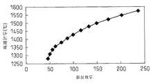
4 is a diagram illustrating a relationship between image brightness and black body temperature.
It is explanatory drawing which shows the measurement result of molten iron temperature obtained from the image brightness of molten iron.
It is a figure which shows the change of the measurement result of the starting line temperature with or without gas influence.
It is a graph which shows the transition of the measurement result of the molten iron temperature by a thermocouple, and the measurement result of the molten iron temperature by a CCD camera.
본 발명에 관한 용선 온도의 검지 방법의 실시 형태의 일례를 도 1에 나타낸다.An example of embodiment of the molten iron temperature detection method which concerns on this invention is shown in FIG.
도 1에 나타내는 예에서는 고로 하부의 출선구(10)로부터 유출되는 용선과 용융 슬래그의 출선류(11)의 휘도를, 휘도 촬상 수단인 CCD 카메라(12)로 연속적으로 촬상하고, 촬상한 각 용선의 휘도로부터 용선 온도를 각각 구하여 용선 평균 온도 T를 산출한다.In the example shown in FIG. 1, the molten iron which flows out from the tap opening 10 of the lower part of a blast furnace, and the brightness | luminance of the molten
본 발명에 관한 용선 온도의 검지 방법은 출선구(10)로부터 취출되는 가스나 흑연에 의한 외란 인자에 의하여 순간적으로 저온되는 용선 온도의 측정값을 제외하고, 고정밀도의 용선 평균 온도 T를 안정적으로 산출할 수 있다.The molten iron temperature detection method according to the present invention stably maintains a high-precision molten iron average temperature T except for a measurement value of the molten iron temperature which is instantaneously low due to the disturbance factor due to the gas or graphite taken out from the
먼저, 용선 평균 온도의 산출 방법에 대하여 자세하게 설명한다.First, the calculation method of molten iron average temperature is demonstrated in detail.
본 발명자들이 출선류를 도 1에 나타내는 측정계로 CCD 카메라를 사용하여 고속 셔터로 옆으로부터 촬상하였더니, 용선과 용융 슬래그가 물과 기름과 같이 분리된 상태로 유출되고 있는 것을 알 수 있었다.When the inventors imaged the ship flow from the side with a high-speed shutter using a CCD camera as the measuring system shown in Fig. 1, it was found that molten iron and molten slag were leaked in a state of being separated like water and oil.
구체적으로는, 도 2에 나타내는 바와 같이, CCD 카메라를 사용하여 셔터 스피드 1/10000초로, 출선류의 적열자발광상을 촬상하면, 어두운 상온 배경 중에 용선과 용융 슬래그의 흐름이 있고, 용선과 용융 슬래그가 분리되어 얼룩상이 되어 있는 것이 관찰되었다.Specifically, as shown in FIG. 2, when a red-light emitting image of outgoing stream is imaged at a shutter speed of 1/10000 sec using a CCD camera, molten iron and molten slag are present in a dark room temperature background. It was observed that was separated and became a spot.
출선류(21) 상에서 약간 어두운 영역이 용선(22)이고, 그에 비해 밝은 영역이 용융 슬래그(23)이다. 또한 용선(22)과 용융 슬래그(23)는 동일한 온도이지만, 방사율은 용융 슬래그(23)가 용선(22)보다 높기 때문에, 열방사 휘도가 크고 더 밝게 관측되고 있다(특허문헌 5 참조).The slightly darker area on the ship flow 21 is the
따라서, 이 방사 휘도의 명암을 이용하여 용선 온도를 측정할 수 있다는 것을 알 수 있었다.Therefore, it turned out that molten iron temperature can be measured using the contrast of this luminance.
그러나, 통상 출선구보다 하류에 위치하는 스키머에서 측정한 값은 출선구에서의 측정값에 비하여 약 50℃ 정도의 저하를 보이지만 용선 온도를 측정하는 중에서, 측정 온도가 스키머에서의 측정 결과보다 상당히 낮아지는 경우가 간혹 나타났다.However, the value measured at the skimmer located downstream from the starting point is about 50 ° C lower than the measured value at the starting point, but during the measurement of the molten iron temperature, the measured temperature is considerably lower than that at the skimmer. Occasionally it appeared.
조사 결과, 용선 휘도의 저하는 출선구로부터 불기 시작하는 가스나 흑연의 영향에 의하여 일어나고, 이에 의하여, 실제의 용선 온도가 더 낮게 측정되는 것을 알 수 있었다.As a result of the investigation, it was found that the decrease in the molten iron luminance was caused by the influence of the gas or graphite which began to blow from the tap hole, whereby the actual molten iron temperature was measured lower.
본 발명자들은 상기 가스나 흑연의 영향이 1 내지 2초 정도의 순간적인 것임에 주목하고, 순간적으로 저온이 되는 용선 온도의 측정값을 제외하고, 용선 평균 온도를 산출함으로써, 용선 평균 온도 T를 안정적으로 측정 가능하게 하는 수법을 밝혀내었다.The inventors note that the influence of the gas or graphite is instantaneous for about 1 to 2 seconds, and the molten iron average temperature T is stabilized by calculating the molten iron average temperature, except for the measured value of the molten iron temperature which becomes instantaneously low temperature. It was found a method to enable measurement.
셔터 스피드 1/10000초의 촬상에 의한 온도 측정 결과의 상세는 이하와 같다.The detail of the temperature measurement result by image pick-up of
특허문헌 1의 제1 도의 No. 2와 같은 온도 상승의 경우의 촬상 결과를 관찰하면, 상기 송풍 가스나 흑연은 관찰되지 않았기 때문에, 정상적인 온도 상승이라고 판단할 수 있었다.No. 1 of FIG. 1 of
따라서, 온도 상승을 이상값으로서 제외하면 온도 측정 정밀도가 악화되는 것을 알 수 있다.Therefore, it can be seen that the temperature measurement accuracy deteriorates when the temperature rise is excluded as an ideal value.
온도 이상 저하의 경향(특허문헌 1의 제1 도의 No. 1 참조)을 나타내는 용선 온도 측정값의 이상값은 확인되었다. 온도 이상 저하의 발생시의 촬상 결과를 관찰하면, 상기 가스나 흑연의 분출이 관찰되었다.The abnormal value of the molten iron temperature measured value which shows the tendency of temperature abnormality fall (refer No. 1 of FIG. 1 of patent document 1) was confirmed. When observing the imaging result at the time of generation | occurrence | production of temperature abnormal fall, the ejection of the said gas and graphite was observed.
상세하게 검토한 결과, 가스나 흑연의 분출에 의한 측정 온도의 이상 저하는 순간적으로 일어나는 것이고, 30℃/초 이상의 온도 구배로 저하하는 것이었다.As a result of the examination in detail, the abnormal decrease in the measured temperature due to the ejection of gas or graphite occurs instantaneously, and was lowered to a temperature gradient of 30 ° C / sec or more.
본 발명에서는 이하의 순서로 이와 같은 측정 온도의 이상값을 노이즈로서 제거하고, 용선 온도의 평균값을 산출한다.In the present invention, such an abnormal value of the measurement temperature is removed as noise in the following procedure, and the average value of the molten iron temperature is calculated.
촬상하여 얻은 복수의 용선 온도를 사용하여 특정 시각의 용선 평균 온도를 산출하는 경우에는 적어도 과거 20초간의 용선 온도를 사용하여 용선 평균 온도를 산출한다.When the molten iron average temperature of a specific time is computed using the some molten iron temperature acquired by imaging, molten iron average temperature is computed using the molten iron temperature for at least the past 20 second.
이상값(異常値)이 측정되는 시간은 길어도 3초 정도이므로, 적어도 과거 20초의 용선 온도를 이용하면 용선 평균 온도를 산출할 수 있다.Since the time at which the ideal value is measured is at least about 3 seconds, the molten iron average temperature can be calculated by using the molten iron temperature of at least the past 20 seconds.
출선류의 촬상은 0.1초 이상 0.5 이하의 주기로 실시한다. 0.5초를 초과하는 주기로 용선 온도를 측정하면 온도 구배를 과소평가할 우려가 있기 때문이고, 0.1초 미만의 주기로 측정하더라도 용선 평균 온도의 측정 정밀도는 변하지 않고 처리가 번잡하게 될 뿐이기 때문이다.The imaging of outgoing flow is performed at a period of 0.1 seconds or more and 0.5 or less. This is because the measurement of the molten iron temperature with a period exceeding 0.5 seconds may underestimate the temperature gradient, and even if it is measured with a period less than 0.1 seconds, the measurement accuracy of the molten iron average temperature does not change, and processing is complicated.
상기한 바와 같이, 온도 측정값의 이상 저하는 30℃/초 이상의 온도 구배로 저하하는 것이고, 또한 용선 평균 온도값으로부터 50℃ 이상 저하하는 특징이 있다.As mentioned above, the abnormal fall of the temperature measured value falls by the temperature gradient of 30 degreeC / sec or more, and also has a characteristic which falls 50 degreeC or more from a molten iron average temperature value.
본 발명에서는 이하와 같이 용선 온도 측정값의 이상값을 판정하고, 용선 평균 온도는 이상값을 제외하고 산출한다.In this invention, the abnormal value of a molten iron temperature measured value is determined as follows, and a molten iron average temperature is calculated except an abnormal value.
임의의 용선 온도 Tx를 얻은 시각으로부터, 1 내지 3초 사이에 미리 정한 시간 전의 용선 온도를 Ty로 한다. Ty를 얻은 시각으로부터 적어도 과거 20초간의 용선 온도를 사용하여 용선 평균 온도 Tave를 산출한다.From the time when the arbitrary molten iron temperature Tx was obtained, let molten iron temperature before the predetermined time between 1-3 seconds be Ty. From the time point at which Ty was obtained, the molten iron average temperature Tave is calculated using the molten iron temperature for at least the past 20 seconds.
용선 온도 Tx가 용선 평균 온도 Tave로부터 50℃ 이상 저하하고, 또한, 용선 온도 Tx와 Ty의 온도 구배가 30℃/초 이상인 경우에는 용선 온도 Ty를 얻은 시각으로부터 Tx를 얻은 시각의 사이에 얻은 용선 온도(Tx, Ty를 포함한다)를 이상값으로 한다.When the molten iron temperature Tx falls by 50 ° C or more from the molten iron average temperature Tave, and the temperature gradient of the molten iron temperature Tx and Ty is 30 ° C / sec or more, the molten iron temperature obtained between the time of obtaining Tx from the time of obtaining the molten iron temperature Ty (Including Tx and Ty) is an ideal value.
용선 온도 Tx를 얻은 시각 이후에 얻게 되는 용선 온도 Tz는 Tz가 용선 평균 온도 Tave보다 10℃ 낮은 온도에 도달할 때까지는 이상값으로 한다.The molten iron temperature Tz obtained after the time of obtaining the molten iron temperature Tx is an ideal value until Tz reaches a
상기한 바와 같이, 이상값이 측정되는 시간은 길어도 3초 정도이므로, 이상 측정 온도를 제거하더라도, 과거 20초간의 용선 온도를 이용하여 용선 평균 온도를 산출하는 것이 가능하다.As described above, since the time at which the abnormal value is measured is at least about 3 seconds, even if the abnormal measurement temperature is removed, it is possible to calculate the molten iron average temperature using the molten iron temperature for the past 20 seconds.
이상의 방법에 기초하여 온도 이상 저하를 노이즈로서 제거하면, 흑연 발생에 의한 측정 온도의 이상값(특허문헌 1의 제1 도의 No. 5 참조)도 측정 온도가 이상이 되는 것은 길어도 3초간 정도이므로, 제거할 수 있다는 것을 알았다.If the temperature abnormality drop is eliminated as noise on the basis of the above-described method, the ideal value of the measurement temperature (see No. 5 in FIG. 1 of FIG. 1) due to graphite generation is also about 3 seconds because the measurement temperature becomes abnormal. It was found that it could be removed.
도 2에는 셔터 스피드 1/10000초에서의 촬상예를 나타냈지만, 본 발명자 등의 검토의 결과, 셔터 스피드는 1/5000초이면 용선 평균 온도를 고정밀도로 측정할 수 있다는 것을 알 수 있었다.Although the imaging example at the shutter speed of 1/10000 second was shown in FIG. 2, as a result of examination by this inventor etc., it turned out that molten iron average temperature can be measured with high precision if shutter speed is 1/5000 second.
다음으로, 구체적인 계측계의 일례에 대하여 설명한다.Next, an example of a specific measurement system is demonstrated.
도 1에 나타내는 바와 같이, CCD 카메라(12)를 그 시야가 출선구(10)의 벽면으로부터 10 내지 30cm의 범위 내의 출선류(11)를 촬상할 수 있는 위치에 부착 고정하여 출선류(11)를 촬상한다. 이 출선류(11)의 단면의 최대 폭은 100 내지 200mm 정도이다.As shown in FIG. 1, the
촬상의 프레임 속도는 1초당 1 내지 200 프레임(이하, 화상이라고도 한다)이다.The frame rate of imaging is 1 to 200 frames per second (hereinafter also referred to as image).
도 1 중의 도면부호 13은 출선통이며, 도면부호 14는 통 커버이다.In Fig. 1,
CCD 카메라(12)는 출선류(11)의 휘도를, 예를 들면 256 계조(階調)로 측정 가능한 카메라이며, 촬상 소자의 노출 시간이 1/5000초 이하인 고속 셔터로 촬상할 수 있는 것이다.The
CCD 카메라(12)는 폭 분해능이 1mm/화소 이하가 되도록, 화소수 및 설치 위치를 선정한다. 폭 분해능을 1mm 이하로 함으로써 출선류의 모양의 세부에 있는 2mm 정도의 사이즈의 선상 및 점상의 부분도 잡을 수 있다.The
노광 시간을 1/10000초 이하로 하면, 촬상한 용선과 용융 슬래그의 출선류에, 상 흐름이 생기는 것을 방지할 수 있으므로, 촬상한 용선의 휘도가 명확하게되고, 출선류의 온도 측정 정밀도가 올라가므로, 고로 내의 온도 변화를 더욱 정확하게 얻을 수 있다.When the exposure time is set to 1/10000 sec or less, since the flow of phase can be prevented in the wire flow of the captured molten iron and the molten slag, the luminance of the captured molten iron becomes clear and the temperature measurement accuracy of the wire flow increases. Therefore, the temperature change in the blast furnace can be obtained more accurately.
노광 시간은 1/20000초 이하이면 더 좋고, 1/30000초 이하로 하면 더욱 좋다.Exposure time is better if it is 1/20000 second or less, and it is more preferable to set it as 1/30000 second or less.
CCD 카메라(12)로 촬상된 화상은 케이블 등을 거쳐 화상 처리 장치(15)에 보내진다. 화상 처리 장치(15)에는 화상 입력 보드를 구비한 컴퓨터 등을 사용할 수 있다.The image picked up by the
화상 처리 장치(15)는 CCD 카메라(12)로 촬상한 화상을 도 3에 나타내는 각 화소의 휘도를 휘도 계조로 분해하여 횡축, 휘도 계조마다의 화소수를 종축으로 히스토그램을 산출하고, 히스토그램 상의 용선 상당 부분에 있어서의 극대 빈출 휘도값을 피크 휘도로서 정한다.The
도 3에 나타내는 히스토그램에서는 3개의 휘도의 피크(이하, 피크 휘도)가 나타난다. 여기에서는 휘도가 작은 것으로부터 배경의 피크 휘도(31), 용선의 피크 휘도(32), 용융 슬래그의 피크 휘도(33)가 나타난다. 이는 용융 슬래그의 방사율이 용선보다 높기 때문에, 용융 슬래그의 열 방사 휘도가 크고, 용선보다 밝게 촬상되는 것에 따른 것이다.In the histogram shown in FIG. 3, three luminance peaks (hereinafter referred to as peak luminances) appear. Here, since the luminance is small, the
256 계조로 휘도를 측정할 수 있는 장치를 이용하였을 경우, 용선의 피크 휘도는 휘도가 80 이상 85 이하인 범위, 용융 슬래그의 피크 휘도는 휘도가 85 이상 120 이하인 범위로 나타나는 것을 알고 있다.When using a device capable of measuring luminance with 256 gray scales, it is known that the peak luminance of molten iron is in the range of 80 to 85 luminance, and the peak luminance of molten slag is in the range of 85 to 120 luminance.
그 후, 전자계산기 등의 연산 장치(16)를 사용하고, 구해진 용선의 피크 휘도로부터 온도 변환식을 사용하여 용선 온도를 산출한다.Thereafter, using
연산 장치(16)는 화상 처리 장치(15) 내에 설치한 것이어도 좋다.The
도 4는 흑체로로 교정한, 온도 변환식의 일례를 나타내는 것이다.4 shows an example of a temperature conversion equation calibrated with a black body furnace.
도 4 중의 흑점(◆)은 실측한 휘도와 흑체 온도의 관계이고, 실선은 실측한 점의 근사 곡선이다. 이 근사 곡선을 나타내는 식이 온도 변환식이고, 용선의 피크 휘도(X)를, 온도 변환식에 대입함으로써 용선 온도(Y)를 산출할 수 있다.The black spot (◆) in FIG. 4 is a relationship between the measured luminance and the black body temperature, and the solid line is an approximation curve of the measured point. The equation showing this approximation curve is a temperature conversion equation, and the molten iron temperature Y can be calculated by substituting the peak luminance X of the molten iron into the temperature conversion equation.
흑체로란, 입사한 방사광을 파장, 입사 방향 및 편광 상태에 관계 없이 흑체로 내의 노벽에서 반사하지 않고 모두 흡수하는 이상적인 상태를 근사적으로 재현한 공지의 장치이다.A black body furnace is a well-known apparatus which approximately reproduces the ideal state which absorbs the incident radiation light without reflecting it from the furnace wall in a black body furnace irrespective of wavelength, incident direction, and polarization state.
흑체로 내에서는 표류광의 영향을 거의 무시할 수 있는 상태로 온도 측정이 가능하게 된다. 흑체로 내의 휘도는 통상 흑체로 내에 아무것도 배치하지 않고, 흑체로 내의 온도를 상승시켜, 그때의 흑체로 내의 휘도를 측정하여 구한다.The temperature can be measured in the black body furnace in such a way that the influence of the stray light can be almost ignored. The luminance in the black body furnace is usually obtained by arranging nothing in the black body furnace, raising the temperature in the black body furnace, and measuring the luminance in the black body furnace at that time.
상기 방법에 의하여, 촬상한 화상마다 용선 온도가 산출되고, 산출된 화상마다의 용선 온도가 연산 장치(16)의 기억 장치에 보존된다.By the above method, the molten iron temperature is calculated for each image picked up, and the molten iron temperature for each calculated image is stored in the storage device of the
연산 장치(16)에 있어서의 처리 수단에서는 임의의 용선 온도 Tx를 얻은 시각으로부터, 1 내지 3초 사이에 미리 정한 시간 전의 용선 온도를 Ty로 하고, Ty를 얻은 시각으로부터 적어도 과거 20초간의 용선 온도를 사용하여 용선 평균 온도 Tave를 산출한다.In the processing means in the
용선 온도 Tx가 용선 평균 온도 Tave로부터 50℃ 이상 저하하고, 또한, 용선 온도 Tx와 Ty의 온도 구배가 30℃/초 이상인 경우에는, 용선 온도 Ty를 얻은 시각에서 Tx를 얻은 시각의 사이에 얻은 용선 온도(Tx, Ty를 포함한다)를 이상값으로 하여 용선 평균 온도를 산출할 때에 제거한다.When the molten iron temperature Tx falls by 50 ° C or more from the molten iron average temperature Tave, and the temperature gradient of the molten iron temperature Tx and Ty is 30 ° C / sec or more, the molten iron obtained between the time when the Tx is obtained at the time of obtaining the molten iron temperature Ty The temperature (including Tx and Ty) is taken as an ideal value and is removed when calculating the molten iron average temperature.
이 방법을, 일례로서 도 5를 참조하면서 설명한다. This method is explained with reference to FIG. 5 as an example.
도 5에는 0.5초 주기로 얻은 복수의 용선 온도를 나타낸다.5 shows a plurality of molten iron temperatures obtained at 0.5 second cycles.
도 5에 있어서, 대부분의 용선 온도의 측정 결과는 Tave를 중심으로 하여 ±10℃의 범위(51) 내에 있지만, 용선 온도가 Tave를 더 급격하게 저하하고 있다는 점(52)이 있다.In FIG. 5, the measurement result of most molten iron temperature is in the
상기와 같은 Tave를 급격하게 저하한 점을 이용하여, 용선 평균 온도 T를 구하면, 용선 온도가 저하한 것으로 오인되고, 예를 들면, 고로의 조업 조건에 대하여 과잉 조치를 강구함으로써 조업 상태를 악화시켜 버릴 우려가 있다.When the molten iron average temperature T is obtained by using the above abruptly reduced Tave, the molten iron temperature is mistaken as being lowered. For example, the operation state is deteriorated by taking an excessive measure for the blast furnace operating conditions. I might throw it away.
이에 처음에, 연산 장치(16)에서 측정된 용선 온도를 이상값으로서 취급하거나 판정한다.Initially, the molten iron temperature measured by the
예를 들면, 경과 시간 4초의 지점에서의 용선 온도 Tx는 1413℃이다. 미리 정한 시간을 2초로 하면, 용선 온도 Tx가 측정된 시각의 2초 전의 용선 온도 Ty는 1525℃이며, Tx와 Ty의 온도 구배는 56℃/초이다.For example, the molten iron temperature Tx at the point of elapsed time 4 seconds is 1413 degreeC. If the predetermined time is 2 seconds, the molten iron temperature Ty before 2 seconds before the molten iron temperature Tx is measured is 1525 ° C, and the temperature gradient between Tx and Ty is 56 ° C / sec.
용선 평균 온도 Tave는 Ty로부터 적어도 과거 20초간의 용선 온도를 사용하여 산출된 용선 평균 온도이다. 도 5의 Tave를 1525℃로 하면, Tx는 Tave로부터 112℃ 저하되어 있다.The molten iron mean temperature Tave is the molten iron mean temperature calculated from Ty using the molten iron temperature for at least the past 20 seconds. When Tave of FIG. 5 is made to 1525 degreeC, Tx is 112 degreeC lowered from Tave.
따라서, 용선 온도 Ty를 얻은 시각으로부터 Tx를 얻은 시각 사이에 얻은 용선 온도(Tx, Ty를 포함한다)는 이상값으로서 용선 평균 온도 T의 산출 시에 제외된다.Therefore, the molten iron temperature (including Tx and Ty) obtained between the time of obtaining molten iron temperature Ty and the time of obtaining Tx is excluded at the time of calculation of molten iron average temperature T as an ideal value.
용선 평균 온도 Tave에 대한 용선 온도 Tx의 저하 온도가 50℃ 미만인 경우에는 저하 온도가 작고, 측정된 온도가 바른 것일 가능성이 있으므로, 이상값이라고 판정하지 않는다.When the fall temperature of the molten iron temperature Tx with respect to the molten iron average temperature Tave is less than 50 degreeC, since a fall temperature is small and a measured temperature may be correct, it is not determined that it is an abnormal value.
측정 온도의 용선 평균 온도 Tave로부터의 이상 저하는 저하의 원인인 가스나 흑연의 영향이 1 내지 2초 정도의 순간적인 것임을 고려하면, 크더라도 300℃ 정도라고 생각할 수 있다.Considering that the abnormal influence from the molten iron mean temperature Tave of the measurement temperature is a moment of about 1 to 2 seconds, the influence of the gas or graphite, which is the cause of the decrease, may be considered to be about 300 ° C even if large.
미리 정한 시간 전의 용선 온도 Ty로부터 Tx로의 온도 저하에 있어서의 온도 구배가 30℃/초 미만인 경우에도, 온도 변화량이 작고, 측정된 온도가 올바른 것일 가능성이 있으므로, 이상값이라고 판정하지 않는다.Even when the temperature gradient in the temperature drop from the molten iron temperature Ty to the Tx before the predetermined time is less than 30 ° C / sec, the temperature change amount is small and the measured temperature may be correct.
이상값이라고 판정하는 조건은 용선 평균 온도 Tave에 대하여 용선 온도 Tx가 50℃ 이상 저하하였을 때로 하였지만, 고로의 조업 조건에 따라서는 80℃ 이상 저하하였을 때나 100℃ 이상 저하하였을 때로 하여도 좋다.The conditions to be determined as an abnormal value were when the molten iron temperature Tx fell by 50 ° C or more with respect to the molten iron average temperature Tave. However, depending on the operating conditions of the blast furnace, the molten iron temperature may be lowered by 80 ° C or more or 100 ° C or more.
다음으로, 연산 장치(16)의 산출 수단으로, 적어도 20초간의 용선 온도에 대하여, 이상값으로 여겨진 측정값을 제외하고, 용선 평균 온도 T를 산출한다.Next, with the calculation means of the calculating
이 방법을, 도 5를 참조하면서 설명한다.This method will be described with reference to FIG. 5.
도 5에 나타내는 바와 같이, 용선 온도의 측정값이 급격하게 저하한 점(52)의 직후에는 측정값이 충분히 오르지 않는 점(53)(여기에서는 2점)이 발생하는 경우가 있다. 이것은 가스와 흑연의 영향이 남아 있기 때문이다.As shown in FIG. 5, the point 53 (two points here) which a measured value does not fully rise may arise immediately after the
이에 상승하기 시작한 용선 온도의 측정값과 용선 평균 온도 Tave와의 차이가 10℃ 이내로 상승할 때까지는 측정값을 이상값으로 판정하기로 하였다.The measured value was determined to be an abnormal value until the difference between the measured value of the molten iron temperature and the molten iron average temperature Tave which started to rise rose to within 10 degreeC.
용선 평균 온도 Tave와 상승하는 용선 온도의 측정값의 차이가 10℃ 이하가 된 점을 정상이라고 판단하는 이유는 차이가 10℃를 초과하는 측정값을 정상적인 것으로서 취급하면, 온도 분포가 너무 넓어져서 용선 온도의 측정 정밀도가 저하될 우려가 있기 때문이다.The reason why it is normal to determine that the difference between the molten iron average temperature Tave and the rising molten iron temperature is 10 ° C. or lower is normal. If the measured value of the difference exceeds 10 ° C. is treated as normal, the temperature distribution becomes too wide and It is because there exists a possibility that the measurement precision of temperature may fall.
용선 평균 온도 T는 상기 이상값이라고 판정된 측정값을 제외하고 산출한다.The molten iron average temperature T is calculated except the measured value determined as the abnormal value.
상기한 바와 같이, 용선 평균 온도의 산출은 적어도 과거 20초간의 용선 온도 측정값을 이용하여 이상 시점으로부터 정상 시점까지의 용선 온도는 제외하고 평균을 구하지만, 이상 시점으로부터 정상 시점까지의 시간은 길어도 3초 정도이기 때문에, 이상 측정값을 제거하더라도 용선 평균 온도의 산출은 가능하다.As described above, the average of the molten iron temperature is calculated using the molten iron temperature measurement value of at least the past 20 seconds except the molten iron temperature from the abnormal time point to the normal time point, but the time from the abnormal time point to the normal time point is long. Since it is about 3 seconds, even if the abnormal measured value is removed, the molten iron average temperature can be calculated.
용선 평균 온도의 산출에 적어도 과거 20초간의 용선 온도 측정값을 사용하는 것은 20초 미만의 사이의 용선 온도 측정값으로부터 용선 평균 온도를 산출하면, 데이터 수가 너무 적으므로, 예를 들면, 우연히 변동한 용선 온도의 영향에 의하여, 용선 평균 온도의 측정 정밀도가 저하될 우려가 있기 때문이다.Using the molten iron temperature measurement for at least the past 20 seconds to calculate the molten iron mean temperature results in too few data when calculating the molten iron average temperature from the molten iron temperature measurement for less than 20 seconds, for example, by accident It is because there exists a possibility that the measurement precision of molten iron mean temperature may fall by influence of molten iron temperature.
용선 평균 온도 T의 산출에 즈음하여서는 25초간의 용선 온도를 사용하면 더 좋고, 30초간의 용선 온도를 사용하면 한층 더 좋다.In the calculation of the molten iron average temperature T, it is better to use the molten iron temperature for 25 seconds, and even better if the molten iron temperature for 30 seconds is used.
이상의 방법에 의하여, 고로로부터의 출선 시의 용선 평균 온도 T를 안정적으로 측정할 수 있으므로, 이 방법을 사용하여, 고로 내의 조업 상태 및 그 변동을 조기에 파악할 수 있다.By the above method, since the molten iron average temperature T at the time of departure from a blast furnace can be measured stably, using this method, it is possible to grasp | ascertain the operating state in a blast furnace, and the fluctuation | variation early.
구체적으로는, 20초마다 구한 복수의 용선 평균 온도 T를 사용하여, 연산 장치(16)의 산출 수단에 의하여, 출선구(11)로부터의 제1 출선의 말기의 용선 평균 온도 Te와, 제2 출선의 초기의 용선 평균 온도 Ts를 산출하고, 제어 장치(17)에 의하여, 고로를 Ts-Te>-15℃가 되도록 조업한다(예를 들면, 특허문헌 6 참조).Specifically, by using the plurality of molten iron average temperatures T obtained every 20 seconds, the molten iron average temperature Te at the end of the first line from the tap-out
제1, 제2 출선은 고로 하부에 설치된 다른 위치의 출선구에서 행하여진다.The 1st and 2nd starting line is performed in the starting point of another position provided in the lower part of blast furnace.
제1 출선과 제2 출선은 일련의 고로의 조업 공정에 있어서, 어떤 시점을 기준시로 하고, 그 기준시 후의 첫 번째와 두 번째의 출선을 각각 의미한다. 이 제1, 제2 출선 시기는 앞의 출선의 종료 시기와 후의 출선의 개시 시기를 간격을 두고 실시하는 경우와 중복하여 실시하는 경우가 있다.The first starting point and the second starting point refer to a certain point of time in the operation process of the blast furnace, and refer to the first and second starting points after the reference time, respectively. These first and second departure times may be carried out in duplicate with the case where the first and second departure times are carried out at intervals between the end time of the previous departure and the start time of the later departure.
중복하여 실시하는 경우에는 후의 출선 개시 시기부터 앞의 출선 종료 시기까지의 시간이 0을 넘고 10분 이하이다.In the case of carrying out in duplicate, the time from the starting point of departure to the previous point of departure is over 10 minutes.
고로 내의 상태가 양호한 경우, 탕류부에 저장된 용선은 체류하지 않고 원활히 유동하고, 제1 출선의 종료시에는 노상 탕류부의 용선이 거의 모두 배출된다.If the condition in the blast furnace is good, the molten iron stored in the molten metal flows smoothly without remaining, and almost all of the molten iron in the open-air molten portion is discharged at the end of the first tapping line.
따라서, 제2 출선의 개시시에는 노 내에서 생성한 지 얼마 안된 용선이 냉각을 받지 않고 배출되므로, Ts의 값은 Te의 값을 크게 밑돌지 않는다.Therefore, at the start of the second starting line, the molten iron just generated in the furnace is discharged without being cooled, so the value of Ts does not significantly fall below the value of Te.
한편, 고로 내의 상태가 나쁜 경우, 노심부나 노바닥 탕류부에 용선의 유동을 간섭하는 불투과층이 생성되고, 제1 출선 종료시에 제2 출선을 실시하는 출선구 부근에, 용선의 일부가 체류한다.On the other hand, when the state in a blast furnace is bad, an impermeable layer which interferes with flow of molten iron will generate | occur | produce in a core part or a furnace bottom flow part, and a part of molten iron will remain in the vicinity of the tap opening which performs a second tapping at the end of a first tapping. do.
따라서, 제2 출선 개시시에는 노상 탕류부에 체류하고, 노벽의 냉각 장치에 의한 냉각이나 불투과층 등에 발열된 저온의 용선이 배출되므로, Ts와 Te의 차이는 -15℃ 이하가 된다.Therefore, since the low temperature molten iron which stays in a hearth water flow part at the start of a 2nd unloading and generate | occur | produces cooling by the cooling apparatus of a furnace wall, an impermeable layer, etc. is discharged, the difference of Ts and Te becomes -15 degrees C or less.
이와 같이, Ts와 Te와의 온도차를 비교함으로써, 고로 내의 조업 상태를 신속히 판정할 수 있기 때문에, 고로 내의 상태가 나쁜 경우, 즉, Ts-Te≤-15℃인 경우에는, 제어 장치(17)에 의해 이하에 나타내는 조치를 취한다.Thus, by comparing the temperature difference between Ts and Te, it is possible to quickly determine the operating state in the blast furnace. Therefore, when the state in the blast furnace is bad, that is, when Ts-Te? By the following measures.
고로 내의 상태가 나쁜 경우, 상기와 같이 고로 내에 불투과층이 생성된다. 이에, 이 불투과층을 소실시키는 방법으로서 (1) 고로 내의 투입 열량을 증대시키고, 불투과층을 직접 가열하여 융융하는 방법, (2) 불투과층의 근방에 고온의 용선을 유통시키고, 용선의 열량에 의하여 불투과층을 융해하는 방법을 들 수 있다.When the state in a blast furnace is bad, an opaque layer is produced in a blast furnace as mentioned above. As a method of dissipating this impermeable layer, (1) a method of increasing the amount of heat input into the blast furnace, directly heating and melting the impermeable layer, and (2) dissolving hot molten iron in the vicinity of the impermeable layer, And a method of melting the impermeable layer by the amount of heat.
구체적으로는, 로 정부(頂部)로부터 고로 내에 장입하는 원료 중의 코크스비(용선 1톤을 제조하는데 필요한 코크스량)를 증대시키고, 노심 및 노 저부 탕류부에 더 높은 연소열을 투입하는 동시에, 불투과층의 근방에 공극율이 큰 코크스에 의하여, 환기성 및 통액성이 높은 영역을 생성하는 방법이 있다.Specifically, the coke ratio (the amount of coke required to produce 1 ton of molten iron) in the raw material charged into the blast furnace from the furnace section is increased, and higher combustion heat is introduced into the core and the furnace bottom water flow, and at the same time, it is impermeable. In the vicinity of the layer, there is a method of generating a region having high air permeability and fluid permeability by coke having a large porosity.
또한, 미분탄의 취입량(용선 1톤을 제조하는데 필요한 미분탄의 취입량)의 증대 또는 열풍의 송풍 온도의 증대에 의하여, 고로 내로의 투입 열량을 증대시키는 방법이 있다. 또한, 이 방법들은 각각 단독으로 실시하여도 좋고, 또한 2 이상을 조합하여 실시하여도 좋다.In addition, there is a method of increasing the amount of heat injected into the blast furnace by increasing the blowing amount of pulverized coal (the blowing amount of pulverized coal required for producing 1 ton of molten iron) or the blowing air temperature of hot air. In addition, these methods may be performed independently, respectively and may be performed in combination of 2 or more.
이에 의하여, 고로의 조업 조건의 변동을 최소한으로 억제할 수 있고, 고로 내를 양호한 상태로 할 수 있다.Thereby, the fluctuation | variation of the operating conditions of a blast furnace can be suppressed to the minimum, and the inside of a blast furnace can be made favorable.
실시예Example
본 발명의 구체적인 실시예에 대하여 설명한다.A specific embodiment of the present invention will be described.
도 1에 나타내는 측정계에서 고로로부터의 출선류의 온도를 측정하였다.The temperature of the outgoing flow from the blast furnace was measured with the measuring system shown in FIG.
용선류를 촬상하는 휘도 촬상 수단에는 화소수가 320×120 화소의 모노칼라의 CCD 카메라(12)를 사용하였다. 촬상된 화상의 1 화소가 실물 사이즈로 1mm에 상당하는 것을 미리 확인하였다.As the luminance image pickup means for picking up the molten air, a
CCD 카메라(12)는 도 1에 나타내는 바와 같이, 용선과 용융 슬래그의 출선류(11)가 화상의 중앙에 위치하도록 관찰 방향을 조정하여 설치하였다. 또한, 고로의 출선구(10)로부터 유출하는 출선류(11)를 CCD 카메라(12)로 횡방향으로부터 촬상하여, 도 2에 나타내는 화상을 얻었다.As shown in FIG. 1, the
촬상은 셔터 스피드 1/10000초로 실시하였다. 촬상의 프레임 속도는 200 프레임/초로 하였다.Imaging was performed at a shutter speed of 1/10000 second. The frame rate of imaging was 200 frames / second.
CCD 카메라(12)로부터 출력되는 영상 신호를 화상 처리 장치(15)에 송신하여 피크 휘도의 판정을 하고, 연산 장치(16)로 휘도-온도 변환 식에 의하여 용선 온도를 산출하였다.The video signal output from the
실시예에서는 이 산출한 온도 데이터를 기초로 상기 발명을 실시하기 위한 형태에 기재한 방법으로, 가스와 흑연의 영향에 의한 이상값을 제외하고, 용선 평균 온도 T를 구하였다. 비교예에서는 이 산출한 온도 데이터로부터 이상값을 제외하지 않고, 용선 평균 온도 T를 구하였다.In the Example, the molten iron average temperature T was calculated | required except the ideal value by the influence of gas and graphite by the method as described in the form for implementing the said invention based on this calculated temperature data. In the comparative example, the molten iron average temperature T was calculated | required without removing an abnormal value from this calculated temperature data.
도 6에 실시예와 비교예의 용선의 측정 온도의 추이를 나타낸다. 도 6 중의 실선은 실시예이며, 점선은 비교예이다.The change of the measurement temperature of the molten iron | metal of an Example and a comparative example is shown in FIG. The solid line in FIG. 6 is an Example, and a dotted line is a comparative example.
실시예에서는 가스와 흑연의 영향이 출선 온도의 측정으로부터 제거되어 있기 때문에, 비교예와 같이 가스나 흑연의 분출이 빈번하게 발생한 것에 의한 출선 온도의 측정값이 국소적으로 급격하게 저하하는 부분(61)이 없고, 출선 시간의 경과에 따라 출선 온도의 측정값이 완만하게 상승하는 것을 확인할 수 있었다.In the embodiment, since the influence of the gas and the graphite is removed from the measurement of the starting point temperature, as in the comparative example, the portion where the measured value of the starting line temperature due to the frequent occurrence of the gas or the graphite is suddenly lowered (61) ), It was confirmed that the measured value of the starting line temperature gradually increased with the progress of the starting time.
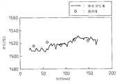
도 7에, 침지형 열전대와 CCD 카메라에 의한 용선 온도 측정의 비교 결과를 나타낸다. 도 7은 CCD 카메라에 의한 측정 결과를 실선, 열전대에 의한 측정 결과를 사각형(◇)으로 각각 나타내고, 2회의 출선에 사용하여 온도가 충분히 상승한 출선통에 출선한 용선을 온도 측정의 대상으로 하고 있다.In FIG. 7, the comparison result of the molten iron temperature measurement by an immersion thermocouple and a CCD camera is shown. Fig. 7 shows the measurement result by the CCD camera as the solid line and the thermocouple measurement result by the square (◇), respectively, and the molten iron drawn to the tapping tube whose temperature has sufficiently risen by using it for two taps is the object of temperature measurement. .
도 7에 나타내는 바와 같이, 열전대에 의한 측정 결과와 CCD 카메라에 의한 측정 결과는 ±10℃ 정도의 범위 내에 들어가 있고, CCD 카메라로 열전대와 동등한 정도의 온도 측정이 가능하다는 것을 알게 되었다.As shown in FIG. 7, it was found that the measurement result by the thermocouple and the measurement result by the CCD camera are within a range of about ± 10 ° C., and the temperature of the temperature equivalent to that of the thermocouple can be measured by the CCD camera.
이상으로부터, 본 발명의 용선 온도의 검지 방법을 사용함으로써, 고로로부터의 출선 시의 용선 온도를 안정적으로 측정하고, 고로 내의 온도 변화를 더 정확하게 파악하고, 그 결과, 고로의 조업 조건의 변동을 최소한으로 억제할 수 있는 것을 확인할 수 있었다.From the above, by using the method for detecting the molten iron temperature of the present invention, the molten iron temperature at the time of departure from the blast furnace can be stably measured, and the temperature change in the blast furnace can be grasped more accurately. It was confirmed that it can be suppressed.
이상, 구체적인 실시 형태를 참조하여 본 발명을 설명하였지만, 본 발명은 상기 실시의 형태에 기재된 구성에 한정되는 것이 아니고, 특허 청구 범위에 기재되어 있는 사항의 범위 내에서 생각할 수 있는 그 밖의 실시 형태나 변형예도 포함하는 것이다.As mentioned above, although this invention was demonstrated with reference to specific embodiment, this invention is not limited to the structure described in the said embodiment, The other embodiment which can be considered within the range of the matter described in a claim, It also includes a modification.
예를 들면, 상기 실시 형태에 있어서는 출선류의 촬상에 CCD 카메라를 사용하였을 경우에 대하여 설명하였지만, 고속 셔터가 가능하면 CCD 이외의 촬상 소자를 이용한 카메라 등의 다른 휘도 촬상 수단도 사용할 수 있다.For example, in the above-described embodiment, the case where a CCD camera is used for imaging the ship-flow is described. However, if a high-speed shutter is possible, other luminance imaging means such as a camera using an imaging element other than CCD can also be used.
상기 실시의 형태나 변형예의 일부 또는 전부를 조합하여 본 발명의 용선 온도의 검지 방법 및 고로의 조업 방법을 구성하는 경우에도 당연하게 본 발명의 권리 범위에 포함된다.The combination of some or all of the embodiments and modifications described above also constitutes the method for detecting the molten iron temperature of the present invention and the operation method of the blast furnace, which are naturally included in the scope of the present invention.
산업상 이용가능성Industrial availability
전술한 바와 같이, 본 발명에 의하면 출선 시의 용선 온도를 안정적으로 측정할 수 있고, 이에 의하여, 고로 내의 온도 변화를 정확하게 파악할 수 있으므로, 고로의 조업에 있어서 온도 저하시의 대응을 신속하게 실시하는 것이 가능해진다.As described above, according to the present invention, it is possible to stably measure the molten iron temperature at the time of starting the ship, and thereby to accurately grasp the temperature change in the blast furnace, so that it is possible to promptly respond to the temperature drop in the operation of the blast furnace. It becomes possible.
또한, 측정된 용선 온도에 기초하여 고로의 조업을 제어할 수 있고, 일시적인 용선 온도의 변화에 의하여, 과잉의 조치를 강구하여 조업 상태를 악화시키는 것이 없어진다.In addition, operation of the blast furnace can be controlled on the basis of the measured molten iron temperature, and by the temporary change in the molten iron temperature, no excessive measures are taken to deteriorate the operating state.
따라서, 본 발명은 철강 산업에 있어서 이용가능성이 큰 것이다.Therefore, the present invention has great applicability in the steel industry.
10출선구
11출선류
12 CCD 카메라(휘도 촬상 수단)
13출선통
14통 커버
15화상 처리 장치
16 연산 장치
17제어 장치
21출선류
22용선상
23슬래그상
31 배경의 피크 휘도
32용선의 피크 휘도
33 용융 슬래그의 피크 휘도
51용선 평균 온도
52용선 온도의 측정값 이상 데이터
53용선 온도의 측정값이 급격하게 저하한 후, 측정값이 충분히 오르지 않는 점
61 가스나 흑연의 분출을 빈번히 볼 수 있던 시간대10 exits
11 ships
12 CCD camera (luminance imaging means)
13 starters
14 barrel cover
15 image processing unit
16 computing device
17 control unit
21 ships
22 charter
23 slag statues
31 Peak luminance at background
32 peak luminance
33 Peak luminance of molten slag
51 molten iron average temperature
52 Above measured value data of molten iron temperature
53 The measured value does not rise sufficiently after the measured value of the molten iron temperature drops sharply.
61 Time zone where gas and graphite jets were seen frequently
Claims (6)
Translated fromKorean상기 출선류를 노출 시간이 1/5000초 이하의 셔터로, 0.1초 이상 0.5초 이하의 주기로 촬상하고, 촬상 화상 내의 용선의 휘도로부터 구하는 용선 온도에 대하여,
임의의 용선 온도 Tx를 얻은 시각으로부터, 1 내지 3초의 사이에 미리 정한 시간 전의 용선 온도를 Ty로 하고,
Ty를 얻은 시각으로부터 적어도 과거 20초간의 용선 온도를 이용하여 용선 평균 온도 Tave를 산출하고,
용선 온도 Tx가 용선 평균 온도 Tave로부터 50℃ 이상 저하하고, 또한, 용선 온도 Tx와 Ty의 온도 구배가 30℃/초 이상인 경우에는 용선 온도 Ty를 얻은 시각으로부터 Tx를 얻은 시각의 사이에 얻은 용선 온도(Tx, Ty를 포함한다)를 이상값으로 판정하고,
또한 용선 온도 Tx를 얻은 시각 이후에 얻을 수 있는 용선 온도 Tz는 Tz가 용선 평균 온도 Tave보다 10℃ 낮은 온도에 도달할 때까지는 이상값으로 판정하고,
임의의 시각에 있어서의 상기 용선 평균 온도 T는 그 시각으로부터 적어도 과거 20초간의 용선 출선 온도 측정값으로부터 상기 이상값을 제외한 적어도 용선 온도를 이용하여 산출하는 것을 특징으로 하는 용선 온도의 검지 방법.In the method of detecting the molten iron temperature which continuously captures the molten iron flowing out from the tap-hole of the blast furnace, obtains the molten iron temperature from the luminance of the molten iron in the captured image, and calculates the molten iron average temperature T.
Regarding the molten iron temperature obtained by capturing the outgoing stream with a shutter having an exposure time of 1/5000 sec or less at a cycle of 0.1 sec. To 0.5 sec.
From the time when the arbitrary molten iron temperature Tx was obtained, let molten iron temperature before the predetermined time between 1 and 3 second be Ty,
The molten iron average temperature Tave is calculated from the molten iron temperature of the past 20 seconds from the time when Ty was obtained,
When the molten iron temperature Tx falls by 50 ° C or more from the molten iron average temperature Tave, and the temperature gradient of the molten iron temperature Tx and Ty is 30 ° C / sec or more, the molten iron temperature obtained between the time of obtaining Tx from the time of obtaining the molten iron temperature Ty (Including Tx and Ty) is determined as an outlier,
In addition, the molten iron temperature Tz obtained after the time of obtaining the molten iron temperature Tx is determined to be an abnormal value until Tz reaches a temperature 10 ° C. lower than the molten iron average temperature Tave.
The molten iron average temperature T at an arbitrary time is calculated from the molten iron starting temperature measurement value for at least the past 20 seconds from the time using at least the molten iron temperature except for the abnormal value.
상기 출선구로부터의 제1 출선의 말기의 용선 평균 온도 Te와,
이어서 실시하는 다음의 제2 출선의 초기의 용선 평균 온도 Ts를 산출하고,
Ts-Te를 구하고,
상기 고로를 Ts-Te>-15℃가 되도록 조업하는 것을 특징으로 하는 고로의 조업 방법.Using the melt average temperature T calculated | required by the detection method of the molten iron temperature of Claim 1,
Molten iron average temperature Te of the last stage of 1st starting line from said starting point,
Next, the molten iron average temperature Ts of the initial stage of the next second starting line to be performed is calculated,
Find Ts-Te,
The blast furnace operating method, characterized in that for operating the blast furnace to be Ts-Te> -15 ℃.
Applications Claiming Priority (3)
| Application Number | Priority Date | Filing Date | Title |
|---|---|---|---|
| JP2008308887 | 2008-12-03 | ||
| JPJP-P-2008-308887 | 2008-12-03 | ||
| PCT/JP2009/070577WO2010064727A1 (en) | 2008-12-03 | 2009-12-02 | Method of determining temperature of molten pig iron and method of operating blast furnace using same |
Publications (2)
| Publication Number | Publication Date |
|---|---|
| KR20110065528A KR20110065528A (en) | 2011-06-15 |
| KR101216657B1true KR101216657B1 (en) | 2012-12-31 |
Family
ID=42233371
Family Applications (1)
| Application Number | Title | Priority Date | Filing Date |
|---|---|---|---|
| KR1020117008945AActiveKR101216657B1 (en) | 2008-12-03 | 2009-12-02 | Method of determining temperature of molten pig iron and method of operating blast furnace using same |
Country Status (3)
| Country | Link |
|---|---|
| JP (1) | JP4580466B2 (en) |
| KR (1) | KR101216657B1 (en) |
| WO (1) | WO2010064727A1 (en) |
Families Citing this family (11)
| Publication number | Priority date | Publication date | Assignee | Title |
|---|---|---|---|---|
| JP5675280B2 (en) | 2010-11-05 | 2015-02-25 | 株式会社東芝 | Diagnostic imaging equipment |
| EP2554959A1 (en)* | 2011-08-02 | 2013-02-06 | Tata Steel IJmuiden B.V. | Method and device for measuring the temperature of hot molten metal |
| JP6512408B2 (en)* | 2015-10-13 | 2019-05-15 | Jfeスチール株式会社 | Method of estimating the temperature of hot metal |
| KR101867715B1 (en)* | 2016-12-12 | 2018-06-14 | 주식회사 포스코 | Temperature measurement apparatus for tap hole of blast furnace |
| CN108090293B (en)* | 2017-12-26 | 2021-04-30 | 国家超级计算天津中心 | Blast furnace hearth and bottom erosion envelope surface determination method |
| KR102135820B1 (en)* | 2018-11-30 | 2020-07-20 | 주식회사 포스코 | Apparatus for judging furnace temperature of blast furnace and method for judging furnace temperature of blast furnace |
| KR102257355B1 (en) | 2019-01-22 | 2021-05-31 | 조선내화 주식회사 | System and method for measuring temperature of refractory |
| CN111593151B (en)* | 2020-04-30 | 2022-03-22 | 柳州钢铁股份有限公司 | On-line detection method for depth of blast furnace tap hole |
| CN112501367A (en)* | 2020-11-17 | 2021-03-16 | 中冶南方工程技术有限公司 | Method and system for quantitatively estimating content of silicon and sulfur in molten iron during blast furnace tapping |
| CN113201611A (en)* | 2021-05-12 | 2021-08-03 | 攀钢集团研究院有限公司 | Method for judging temperature change trend in blast furnace ironmaking |
| JP2024123991A (en)* | 2023-03-02 | 2024-09-12 | 株式会社神戸製鋼所 | Furnace heat prediction data creation device and method, and furnace heat prediction device and method |
Citations (2)
| Publication number | Priority date | Publication date | Assignee | Title |
|---|---|---|---|---|
| JP2006119110A (en) | 2004-09-24 | 2006-05-11 | Nippon Steel Corp | Blast furnace tapping temperature measuring method and measuring device |
| JP2007022651A (en) | 2005-07-13 | 2007-02-01 | Yuichiro Sakai | Inspection method for discrimination of heat seal defects on packaging |
Family Cites Families (4)
| Publication number | Priority date | Publication date | Assignee | Title |
|---|---|---|---|---|
| JPH075045A (en)* | 1993-06-18 | 1995-01-10 | Daido Steel Co Ltd | Method and apparatus for detecting molten metal surface temperature of induction furnace |
| JPH09174228A (en)* | 1995-12-26 | 1997-07-08 | Tokai Carbon Co Ltd | Slag outflow detection method |
| JP5049956B2 (en)* | 2005-04-04 | 2012-10-17 | フィッシャー−ローズマウント システムズ,インコーポレイテッド | Statistical processing methods used to detect abnormal situations |
| JP4926790B2 (en)* | 2007-04-03 | 2012-05-09 | 新日本製鐵株式会社 | Blast furnace operation method |
- 2009
- 2009-12-02KRKR1020117008945Apatent/KR101216657B1/enactiveActive
- 2009-12-02JPJP2010517629Apatent/JP4580466B2/enactiveActive
- 2009-12-02WOPCT/JP2009/070577patent/WO2010064727A1/enactiveApplication Filing
Patent Citations (2)
| Publication number | Priority date | Publication date | Assignee | Title |
|---|---|---|---|---|
| JP2006119110A (en) | 2004-09-24 | 2006-05-11 | Nippon Steel Corp | Blast furnace tapping temperature measuring method and measuring device |
| JP2007022651A (en) | 2005-07-13 | 2007-02-01 | Yuichiro Sakai | Inspection method for discrimination of heat seal defects on packaging |
Also Published As
| Publication number | Publication date |
|---|---|
| JP4580466B2 (en) | 2010-11-10 |
| JPWO2010064727A1 (en) | 2012-05-17 |
| WO2010064727A1 (en) | 2010-06-10 |
| KR20110065528A (en) | 2011-06-15 |
Similar Documents
| Publication | Publication Date | Title |
|---|---|---|
| KR101216657B1 (en) | Method of determining temperature of molten pig iron and method of operating blast furnace using same | |
| KR100548119B1 (en) | Temperature measuring device and measuring method of molten metal | |
| JP6602238B2 (en) | Method for estimating melt level in vertical furnace | |
| JP6414102B2 (en) | Refining furnace discharge flow determination apparatus, refining furnace discharge flow determination method, and molten metal refining method | |
| TWI804075B (en) | Operation method of converter and blowing control system of converter | |
| JP6242329B2 (en) | Hot metal quantity measuring method in vertical furnace and measuring device | |
| CN110631709A (en) | A non-contact molten steel temperature detection method for converter steelmaking | |
| JP6179286B2 (en) | Blast furnace operating status judgment method | |
| JP6164173B2 (en) | Converter discharge flow determination device, converter discharge flow determination method, hot metal pretreatment method, and converter pretreatment operation method | |
| JP2015052148A (en) | Control method based on blast furnace operation status judgment | |
| JP4516854B2 (en) | Blast furnace tapping temperature measuring method and measuring device | |
| JP5444692B2 (en) | Slag outflow detection method | |
| JP7256365B2 (en) | Slag quantification method | |
| Viale et al. | Application of on-line infrared thermography in steel making industry | |
| JP4146420B2 (en) | Blast furnace tapping temperature and hot metal / molten slag mixing ratio measurement method | |
| KR20120073412A (en) | Apparatus for preventing geberation of naked molten metal | |
| Ayres et al. | Measurement of thickness of oxygen lance skull in LD converters using artificial vision | |
| US20240377137A1 (en) | Systems and methods to evaluate spray cooling coverage of graphite furnace electrodes | |
| JP2023103049A (en) | Blowing control method for converter | |
| KR20250059501A (en) | Method for estimating the amount of exclusion | |
| KR102200133B1 (en) | Apparatus and method for measuring blast furnace temperature | |
| KR102271300B1 (en) | Apparatus and method for monitoring tapping of tapping of blast furnace | |
| Sugiura et al. | Development of A New Technique for Continuous Molten Steel Temperature Measurement | |
| KR20230013096A (en) | Converter blowing control method and converter blowing control system | |
| PLC | Smart Raking System Based on Computer Vision for DeSulphurisation Plant |
Legal Events
| Date | Code | Title | Description |
|---|---|---|---|
| A201 | Request for examination | ||
| PA0105 | International application | Patent event date:20110419 Patent event code:PA01051R01D Comment text:International Patent Application | |
| PA0201 | Request for examination | ||
| PG1501 | Laying open of application | ||
| E701 | Decision to grant or registration of patent right | ||
| PE0701 | Decision of registration | Patent event code:PE07011S01D Comment text:Decision to Grant Registration Patent event date:20121002 | |
| GRNT | Written decision to grant | ||
| PR0701 | Registration of establishment | Comment text:Registration of Establishment Patent event date:20121221 Patent event code:PR07011E01D | |
| PR1002 | Payment of registration fee | Payment date:20121224 End annual number:3 Start annual number:1 | |
| PG1601 | Publication of registration | ||
| FPAY | Annual fee payment | Payment date:20151118 Year of fee payment:4 | |
| PR1001 | Payment of annual fee | Payment date:20151118 Start annual number:4 End annual number:4 | |
| FPAY | Annual fee payment | Payment date:20161122 Year of fee payment:5 | |
| PR1001 | Payment of annual fee | Payment date:20161122 Start annual number:5 End annual number:5 | |
| FPAY | Annual fee payment | Payment date:20171120 Year of fee payment:6 | |
| PR1001 | Payment of annual fee | Payment date:20171120 Start annual number:6 End annual number:6 | |
| FPAY | Annual fee payment | Payment date:20181129 Year of fee payment:7 | |
| PR1001 | Payment of annual fee | Payment date:20181129 Start annual number:7 End annual number:7 | |
| FPAY | Annual fee payment | Payment date:20191202 Year of fee payment:8 | |
| PR1001 | Payment of annual fee | Payment date:20191202 Start annual number:8 End annual number:8 | |
| PR1001 | Payment of annual fee | Payment date:20201201 Start annual number:9 End annual number:9 | |
| PR1001 | Payment of annual fee | Payment date:20211201 Start annual number:10 End annual number:10 | |
| PR1001 | Payment of annual fee | Payment date:20221121 Start annual number:11 End annual number:11 | |
| PR1001 | Payment of annual fee | Payment date:20231120 Start annual number:12 End annual number:12 | |
| PR1001 | Payment of annual fee | Payment date:20241121 Start annual number:13 End annual number:13 |