KR101215983B1 - Ultrasonic device and method for tissue coagulation - Google Patents
Ultrasonic device and method for tissue coagulationDownload PDFInfo
- Publication number
- KR101215983B1 KR101215983B1KR1020047019797AKR20047019797AKR101215983B1KR 101215983 B1KR101215983 B1KR 101215983B1KR 1020047019797 AKR1020047019797 AKR 1020047019797AKR 20047019797 AKR20047019797 AKR 20047019797AKR 101215983 B1KR101215983 B1KR 101215983B1
- Authority
- KR
- South Korea
- Prior art keywords
- ultrasonic
- tissue
- tolerance
- applicator
- coagulation
- Prior art date
- Legal status (The legal status is an assumption and is not a legal conclusion. Google has not performed a legal analysis and makes no representation as to the accuracy of the status listed.)
- Expired - Fee Related
Links
Images


Classifications
- A—HUMAN NECESSITIES
- A61—MEDICAL OR VETERINARY SCIENCE; HYGIENE
- A61B—DIAGNOSIS; SURGERY; IDENTIFICATION
- A61B18/00—Surgical instruments, devices or methods for transferring non-mechanical forms of energy to or from the body
- A61B18/18—Surgical instruments, devices or methods for transferring non-mechanical forms of energy to or from the body by applying electromagnetic radiation, e.g. microwaves
- A—HUMAN NECESSITIES
- A61—MEDICAL OR VETERINARY SCIENCE; HYGIENE
- A61N—ELECTROTHERAPY; MAGNETOTHERAPY; RADIATION THERAPY; ULTRASOUND THERAPY
- A61N7/00—Ultrasound therapy
- A61N7/02—Localised ultrasound hyperthermia
- A—HUMAN NECESSITIES
- A61—MEDICAL OR VETERINARY SCIENCE; HYGIENE
- A61B—DIAGNOSIS; SURGERY; IDENTIFICATION
- A61B17/00—Surgical instruments, devices or methods
- A61B17/00491—Surgical glue applicators
- A61B2017/00504—Tissue welding
- A—HUMAN NECESSITIES
- A61—MEDICAL OR VETERINARY SCIENCE; HYGIENE
- A61B—DIAGNOSIS; SURGERY; IDENTIFICATION
- A61B17/00—Surgical instruments, devices or methods
- A61B17/32—Surgical cutting instruments
- A61B17/320068—Surgical cutting instruments using mechanical vibrations, e.g. ultrasonic
- A61B17/320092—Surgical cutting instruments using mechanical vibrations, e.g. ultrasonic with additional movable means for clamping or cutting tissue, e.g. with a pivoting jaw
- A61B2017/320093—Surgical cutting instruments using mechanical vibrations, e.g. ultrasonic with additional movable means for clamping or cutting tissue, e.g. with a pivoting jaw additional movable means performing cutting operation
- A—HUMAN NECESSITIES
- A61—MEDICAL OR VETERINARY SCIENCE; HYGIENE
- A61B—DIAGNOSIS; SURGERY; IDENTIFICATION
- A61B17/00—Surgical instruments, devices or methods
- A61B17/32—Surgical cutting instruments
- A61B17/320068—Surgical cutting instruments using mechanical vibrations, e.g. ultrasonic
- A61B17/320092—Surgical cutting instruments using mechanical vibrations, e.g. ultrasonic with additional movable means for clamping or cutting tissue, e.g. with a pivoting jaw
- A61B2017/320094—Surgical cutting instruments using mechanical vibrations, e.g. ultrasonic with additional movable means for clamping or cutting tissue, e.g. with a pivoting jaw additional movable means performing clamping operation
- A—HUMAN NECESSITIES
- A61—MEDICAL OR VETERINARY SCIENCE; HYGIENE
- A61B—DIAGNOSIS; SURGERY; IDENTIFICATION
- A61B17/00—Surgical instruments, devices or methods
- A61B17/32—Surgical cutting instruments
- A61B17/320068—Surgical cutting instruments using mechanical vibrations, e.g. ultrasonic
- A61B17/320092—Surgical cutting instruments using mechanical vibrations, e.g. ultrasonic with additional movable means for clamping or cutting tissue, e.g. with a pivoting jaw
- A61B2017/320095—Surgical cutting instruments using mechanical vibrations, e.g. ultrasonic with additional movable means for clamping or cutting tissue, e.g. with a pivoting jaw with sealing or cauterizing means
Landscapes
- Health & Medical Sciences (AREA)
- Life Sciences & Earth Sciences (AREA)
- Veterinary Medicine (AREA)
- Engineering & Computer Science (AREA)
- Biomedical Technology (AREA)
- Nuclear Medicine, Radiotherapy & Molecular Imaging (AREA)
- Animal Behavior & Ethology (AREA)
- General Health & Medical Sciences (AREA)
- Public Health (AREA)
- Radiology & Medical Imaging (AREA)
- Surgery (AREA)
- Physics & Mathematics (AREA)
- Electromagnetism (AREA)
- Otolaryngology (AREA)
- Heart & Thoracic Surgery (AREA)
- Medical Informatics (AREA)
- Molecular Biology (AREA)
- Surgical Instruments (AREA)
Abstract
Translated fromKoreanDescription
Translated fromKorean본 발명은 일반적으로 외과용 도구에 관한 것으로서, 특히 환자 조직의 응고에 사용되는 초음파 외과용 도구에 관한 것이다. FIELD OF THE INVENTION The present invention relates generally to surgical instruments, and more particularly to ultrasonic surgical instruments used for coagulation of patient tissue.
출혈의 지혈 또는 조직의 잠재적 출혈은 개복 또는 복강경 수술에서 매우 중요하다. 조직을 응고시키기 위한 지혈에 몇가지 방법들이 현재 사용되어지고 있다. 봉합은 보다 큰 혈관과 장기에서 안전하고 신뢰성이 있어서 공통적으로 사용되어지고 있다. 그러나 작은 혈관이나 장기 또는 복합적인 출혈을 포함하고 있는 상황에서 이를 사용하는데는 어려움이 있다. 단극성을 가지는 전기적 외과 수술은 조직이 응고를 하도록 전기적인 열을 가하여 태움으로써 수술을 수행한다. 이러한 방법은 작은 혈관이나 장기에는 효과적이지만, 습한 환경에서는 전기적 부유 상태로 인하여 근접된 조직에 바람직하지 않은 열적 손상을 일으킬 수 있다. 양극성의 외과 시술 또한 조직에 전기적인 열을 가하는 방법으로 시행되고 단극성의 전기시술보다 전기적 조건에 있어서 향상된 제어 능력을 제공한다. 양극성의 장비들은 봉(electrode)이 조직에 밀착됨으로써 프로브를 떼어낼 때 응고된 조직이 다시 개봉되어 출혈을 하게 되어 조직에 상처를 입힐 수 있다. 초음파 기구는 지혈을 위하여 조직에 마찰을 부여하는 빠른 진동에 의한 마찰열을 이용한다. Hemostasis of bleeding or potential bleeding of tissue is very important in laparotomy or laparoscopic surgery. Several methods are currently used for hemostasis to coagulate tissue. Sutures are commonly used because they are safe and reliable in larger blood vessels and organs. However, it is difficult to use it in situations involving small blood vessels, organs or complex bleeding. Electrosurgical surgery with unipolarity performs surgery by applying electrical heat to allow tissue to coagulate. This method is effective for small blood vessels or organs, but in wet environments, electrical stray conditions can cause undesirable thermal damage to adjacent tissues. Bipolar surgical procedures are also performed by applying electrical heat to tissues and provide improved control over electrical conditions than unipolar electrical procedures. Bipolar instruments can cause damage to the tissue by sticking the electrode to the tissue, causing the coagulated tissue to reopen and bleed when the probe is removed. Ultrasonic instruments use frictional heat due to rapid vibrations that impart friction to tissue for hemostasis.
조직의 절개와 응고를 위한 초음파 장비는 알려져 있다. 이러한 장비는 절개와 동시에 응고와 같은 외과적인 특징을 구성하는 초음파의 구성에 있어서, 종방향으로 진동을 수행한다. 클램핑 과정은 진동의 구성물과 외과용 클램프의 사이의 조직의 접촉을 향상시킴으로써 절개와 응고를 향상시키는 발명이 알려져 있다. 발라무스(Balamuth)의 미국 특허 제 3,862,630 호와 미국 특허 제 3,636,943 호에 두 가지 형태의 초음파 외과 기구가 공개되어 있다. 동시에 조직의 절개와 응고를 하기 위한 첫번째 기구와 두번째 조직의 종합적인 단층을 연결시키기 위한 기구이다. 조직을 종합적으로 연결시키는 기구는 초음파 진동 부재와 클램프 기계 구조를 가지고 있다. 상기 장비는 세로 방향의 진동 방향과 클램프 기계구조의 작업 표면이 서로 수직적이어서, 조직은 클램핑 작업 표면과 초음파 진동 구성물의 표면 사이에서 압력을 받게 된다. 이러한 "end-on" 방식은 상기 초음파 진동 부재와 클램프 기계조직 사이의 지역에서 클램프 처리되는 조직을 나중에 처리될 것이 요구되는 조직과 이를 횡방향으로 차단하고 있고, 이로 인하여 외과적 응용을 위한 도구의 이용에 심각한 제약을 받게 된다. 왜냐하면 조직은 수술 가위로 하는 방식으로는 처리할 수 없기 때문이다. Ultrasound equipment for incision and coagulation of tissues is known. Such equipment performs oscillation in the longitudinal direction in the construction of ultrasound, which, at the same time as the incision, constitutes surgical features such as coagulation. Clamping processes are known to improve incision and coagulation by enhancing the contact of tissue between the components of vibration and the surgical clamp. Two types of ultrasound surgical instruments are disclosed in Balamuth, US Pat. No. 3,862,630 and US Pat. No. 3,636,943. At the same time, it is a mechanism for connecting the first and second tissues of the comprehensive structure of the incision and coagulation. The mechanism for comprehensively connecting the tissue has an ultrasonic vibration member and a clamp machine structure. The equipment is perpendicular to the longitudinal direction of vibration and the working surface of the clamping mechanism so that the tissue is pressed between the clamping working surface and the surface of the ultrasonic vibration component. This "end-on" approach intercepts the tissue to be clamped later in the region between the ultrasonic vibrating member and the clamp mechanical tissue and laterally, thereby providing a tool for surgical applications. There will be severe restrictions on use. This is because tissue cannot be processed by surgical scissors.
데이비슨(Davidson)의 미국 특허 제 5,322,055 호에 연속적으로 조직을 절개하고 응고시키는 초음파 진동 부재와, 초음파 진동 부재의 말단 끝에서 진동하는 세로 방향으로 평행으로 연장된 외과 수술 날을 포함하는 초음파 진동 구성물이 공개되어 있다. 이 발명은 테두리에서 연장된 외과 수술용 날로부터 기인된 강화된 절개 능력과, 대칭 방향으로의 클램프 기계 구조와 초음파 부재를 제공된 조직에 접근하게 하는 기능을 향상시킨 것이다. 클램프 기계구조는 기술된 절개과 응고 효과의 성취를 위하여 초음파 진동 부재에 대하여 매우 근접되도록 설계되었다. 이러한 설계에서 향상된 절개 기능은 연장된 말단부를 가지는 외과용 날의 진동과 상기 클램프 기계구조에 대응되는 날의 완전한 근접 설계에서 기인한 것이다. In US Pat. No. 5,322,055 to Davidson, an ultrasonic vibration component comprising an ultrasonic vibration member for continuously cutting and coagulating tissue and a longitudinally extending surgical blade vibrating at the distal end of the ultrasonic vibration member It is open. This invention improves the enhanced incision ability resulting from the surgical blade extending from the rim, and the ability to access the tissue provided with the clamp machine structure and the ultrasonic member in the symmetric direction. The clamp mechanism is designed to be very close to the ultrasonic vibration member in order to achieve the described incision and coagulation effects. The improved incision in this design is due to the vibration of the surgical blade with the extended distal end and the complete proximity design of the blade corresponding to the clamp mechanism.
만나(Manna)의 미국 특허 제 6,193,709 호에 초음파 진동 부재의 말단에 날을 가지고 있는 초음파 부재와 세로의 진동에 축 방향 예각의 모양으로 된 날을 가진 클램프 기계구조와 초음파 진동 부재가 시술되는 조직의 연속적인 절개과 응고를 위한 장치가 공개되어 있다. 이 특허는 수술과 향상된 진료 동안에 외과 집도와 칼날 사이의 조직 접촉을 강화한다고 주장한다. 외과 집도는 기술된 절개과 응고 효과를 성취하기 위한 초음파 진동 구성물에 대하여 완전히 밀착되도록 설계되었다. 이러한 설계에서 향상된 절개 행위는 클램프 기계 구조에 대한 날의 완벽한 밀착과 세로 방향의 진동의 축에 대한 예각 방향의 칼날의 진동에서 기인된다. US Patent No. 6,193,709 to Manna describes a clamping mechanism having an ultrasonic member having a blade at the distal end of the ultrasonic vibration member and a blade shaped in the form of an axial acute angle in longitudinal vibration, and of the tissue in which the ultrasonic vibration member is to be treated. Apparatuses for continuous incision and coagulation are disclosed. This patent claims to strengthen the tissue contact between surgical implant and blade during surgery and improved care. Surgical guides are designed to be fully in contact with the ultrasonic vibration components to achieve the described incision and coagulation effects. The improved cutting behavior in this design is due to the complete contact of the blade to the clamp machine structure and the vibration of the blade in an acute direction relative to the axis of longitudinal vibration.
미야와키(Miyawaki)의 미국 특허 제 6,193,709 호에 클램프 기계구조와 초음파 진동 부재가 수행하는 절개와 응고를 위한 초음파 외과 장치가 공개되어 있다. 그래서, 클램프는 초음파 진동 부재의 말단 끝 부분의 이동을 따라갈 수 있다. 이 발명은 초음파 진동 부재와 향상되고 연관된 수행을 하는 밀접한 외과 집도 사이의 잠재적인 차이를 제거하는 성공적인 기계구조를 제공한다고 주장하고 있다. 클램프 기계구조는 절개와 응고와 같를 성취하기 위한 초음파 진동 구성물에 대하여 매우 근접하게 접근되도록 설계되었다. US Patent No. 6,193,709 to Miyawaki discloses an ultrasonic surgical device for incision and coagulation performed by a clamp mechanism and an ultrasonic vibration member. Thus, the clamp can follow the movement of the distal end of the ultrasonic vibration member. This invention claims to provide a successful mechanism that eliminates the potential difference between the ultrasonic vibrating member and the close surgical concentrator that performs the improved and associated performance. The clamp mechanism is designed to be in close proximity to the ultrasonic vibration component to achieve such as incision and solidification.
초음파 진동 부재와 클램프 기계구조에 있어서 향상된 응고 효과를 성취하기 위한 차이를 만들어낼 목적으로 초음파 진동 부재와 관련된 클램프 기계 구조의 제한된 접근을 위한 장치에 대한 발명은 없다. 선행 기술에 있어서 상기 초음파 부재에 대응하여 클램프를 잡는 것은 조직의 절개를 아주 당연한 것으로 여겨왔다. 외과의는 바람직하지 않은 절개에 대한 응고에서 기인하는 것을 어떻게 해야 하는지를 알 수 있는 방법이 없다. 이러한 선행 기술들은 초음파 진동 부재의 모양과 클램프 기계구조의 뾰족한 부분의 모양에 관계 없이 초음파 진동 부재에 대하여 집게와 완전히 밀착하여 동시 절개과 응고가 가능하도록 설계되었다. 절개없이 조직을 응고시키는 외과 수술은 진행하는 동안에 있어서 매우 이득이 있다. 선행된 발명에서 이 두 가지 과정을 신뢰성 있게 분리하는 것은 불가능하다. 그러므로, 외과적 초음파 장치의 응고 능력을 향상시키고 독립적인 절개과 응고의 능력을 제 할 필요가 있다. There is no invention of an apparatus for limited access of a clamp machine structure associated with an ultrasonic vibration member for the purpose of making a difference for achieving an improved coagulation effect in the ultrasonic vibration member and the clamp mechanism. In the prior art, holding the clamp in response to the ultrasonic member has taken the incision of the tissue quite natural. The surgeon has no way of knowing what to do due to coagulation for the undesirable incision. These prior arts are designed to be in close contact with the forceps against the ultrasonic vibrating member and to allow simultaneous incision and solidification regardless of the shape of the ultrasonic vibrating member and the shape of the sharp part of the clamping mechanism. Surgical procedures that coagulate tissue without incisions are very beneficial during the ongoing process. In the preceding invention, it is impossible to reliably separate these two processes. Therefore, there is a need to improve the coagulation ability of surgical ultrasound devices and to eliminate the ability of independent incisions and coagulation.
우선적 응고 장치의 수행능력의 부족은 문헌에 기록되어 왔다.(예를 들어 스리박 외(Srivak H, et al)의 "The Use of Bipolar Cautery, Laparsonic Coagulating Shears, and Vascular Clips for Hemostatis of Small and Medium-sized Vessels" 서지칼 엔도스코프(Surgical Endoscopy), 12(2):183-85 (1998 년 2 월) 및 랜드먼(Landman, J)의 (워싱턴 대학)(Washington University), "Comparison of the Ligasure System, Bipolar Electrosurgery, Harmonic Scalpel, Titanium Clips, Endo-GIA, and Sutures for Laparoscopic Vascular Control in a Porcine Model" 미주리주 루이스가에 소재하는 미국 외과 의사 협의회(the Society for American Gastrointestinal Endoscopic Surgeons, St. Louis, Missouri) (2001 년 4 월 10 일 - 21 일)). 이러한 연구들은 복부 초음파 응고 전단(LCS)특허에 언급된 데이비슨(Davidson)에 의하여 담당된 기술이 사용된 존슨 엔드 존슨(Johnson & Johnson)에 의하여 제조되고 배포된 것을 포함하고 있다. 스리박(Spivak)이 저술한 문헌은 LCS 와 300mm의 Hg 를 돼지의 작거나 중간 크기의 혈관 속에 혈액 압력의 실패점 또는 최대점까지 증가시킴으로써 이를 테스트하였다. 그리고, 저자는 개인적으로 안전이 고려된 장치가 일괄적으로 성공적인 장치는 아니라고 결론지었다. LCS 장치는 작은 혈관 테스트에서의 모든 부분에서는 성공적이나 2 가지의 완전한 실패가 있다. 열 두번의 중간 크기의 혈관에서의 테스트와 중간 크기의 혈관이 지정된 압력의 제한에 도달되기 전에 출혈을 시작하는 경우의 두 가지 추가적인 예이다. 이것은 33%의 받아들일 수 없는 실패율을 가지고 있다. 저자의 기술한 바에 따르면, LCS 는 LCS 가 성공적인 중간 크기의 혈관에 적용하기 위해서는 적절한 크기와 제대로 훈련된 외과의사를 필요로 한다. 추가적으로 저자는 외과의사는 초기 지혈에 실패했을 경우에 양자 택일을 할 수 있는 방법을 가지라고 권유하고 있다. 유사하게 랜드먼(Landman)은 혈관을 봉합하는 다양한 요법들을 비교했다. 동맥에 있어서, 83% 의 성공률을 가지고 5/6 번 성공을 했다. 정맥에서 LCS 는 50%의 성공률을 가지고 3/6 번 성공을 했다. 그러므로, 외과적 응고 장치에서 중대한 기술 발전이 필요한 것은 명백하다. The lack of performance of preferential coagulation devices has been documented in the literature (see, for example, "The Use of Bipolar Cautery, Laparsonic Coagulating Shears, and Vascular Clips for Hemostatis of Small and Medium" by Srivak H, et al. -sized Vessels Surgical Endoscopy, 12 (2): 183-85 (February 1998) and Washington University, Landman, J, "Comparison of the Ligasure" System, Bipolar Electrosurgery, Harmonic Scalpel, Titanium Clips, Endo-GIA, and Sutures for Laparoscopic Vascular Control in a Porcine Model "the Society for American Gastrointestinal Endoscopic Surgeons, St. Louis, Missouri) (April 10-21, 2001). These studies include those manufactured and distributed by Johnson & Johnson, who used the techniques covered by Davidson, mentioned in the Abdominal Ultrasound Coagulation Shear (LCS) patent. Spivak's literature tested this by increasing the LCS and 300 mm Hg to the point of failure or maximum of blood pressure in small or medium blood vessels of pigs. And the author concluded that personally considered devices are not all successful devices. The LCS device is successful in all parts of small vessel tests but there are two complete failures. There are two additional examples of testing on twelve medium sized vessels and when the medium sized vessels begin bleeding before the specified pressure limit is reached. This has an unacceptable failure rate of 33%. According to the authors, LCS requires adequate size and a properly trained surgeon to apply LCS to successful medium-sized vessels. In addition, the authors recommend that the surgeon have an alternative method in case of initial hemostasis failure. Similarly, Landman compared various therapies for suturing blood vessels. In the arteries, success was 5/6 with 83% success. In the vein, LCS had 3/6 successes with a 50% success rate. Therefore, it is clear that significant technological advances are needed in surgical coagulation devices.
외과 초음파 장비들의 응고 성능의 충분한 향상에 대한 의미는 지금 발견되어 지고 있다. 첫번째로, 응고 성능은 동시적이기보다 순차적이기 때문에 그 장비들의 응고와 절개 작용에 의에 분리되어져 향상될 수 있다. 순차적이던 반대 방향의 순서가 절개에 우선하여 응고 작용이 도움이 될 수 있다고 증명이 되었다. 순차적 접근은 조직이 응고되어 지고 온도가 떨어질 시간을 벌어준다. 그래서, 어떤 절개 행위 이전에 놓여지게 된다. 출혈되는 조직은 전체적으로 이러한 경우를 피하게 해 줄 수 있다. 본 발명은 도구를 한번의 쥠작용으로 연속적인 응고와 절개 단계를 수행하는 것을 달성하였으며, 이것은 조직의 쥠작용은 한번 응고가 달성되면 절개를 위한 목적으로서 도구를 선택을 가지지 않는다는 의미이다. 두번째로, 응고 작용은 공차 표면과 초음파 진동 작용기와의 공차(clearance)를 제공함으로써 향상되고 조직의 흐름이 주의깊게 제어된 방법으로서 이루어질 것이다. 사전에 결정된 공차 내에서의 조직의 흐름(flow, 충분한 열로 형체를 갖추며 이동하는 조직의 특성)은 공개된 방법으로 이미 절개과 응고를 동시에 한 조직 보다 적은 재출혈량을 요구하는 응고된 조직의 구역을 만든다. 상기 사전 결정된 공차가 약 0.075 mm 에서 약 1.9 mm 사이에서 조심스럽게 조절되었다면 가장 효과적인 응고 효과를 얻을 수 있다는 것이 발견되었다. 상기 사전 결정된 공차가 약 0.075 mm 보다 적다면 동시 절개 작업이 일어날 수 있다는 것도 발견되었다. 상기 사전 결정된 공차가 약 1.9 mm 보다 크다면, 충분하지 않은 조직의 흐름이 발생하고 완전한 응고가 일어나지 않을 수도 있다는 것도 발견되었다. Significant improvements in the coagulation performance of surgical ultrasound devices have now been found. First, the coagulation performance is sequential rather than simultaneous and can be improved separately due to the coagulation and incision of the equipment. It was proved that coagulation could be helpful, with sequential reversed order prior to incision. The sequential approach gives the tissues time to solidify and cool down. Thus, it is placed before any incision. Bleeding tissue can help to avoid this overall. The present invention has achieved the successive coagulation and incision steps of the tool in one action, which means that once the coagulation is achieved, the tool has no choice as an object for the incision. Secondly, the coagulation action will be enhanced by providing a clearance between the tolerance surface and the ultrasonic vibrator and the flow of tissue will be achieved in a carefully controlled manner. Tissue flow within predetermined tolerances (characteristic of tissue moving in shape with sufficient heat) creates a zone of coagulated tissue that requires less rebleeding than tissue that has already undergone both incision and coagulation in an open manner. . It has been found that the most effective coagulation effect can be obtained if the predetermined tolerance is carefully adjusted between about 0.075 mm to about 1.9 mm. It has also been found that simultaneous incision operation may occur if the predetermined tolerance is less than about 0.075 mm. It has also been found that if the predetermined tolerance is greater than about 1.9 mm, insufficient tissue flow may occur and full coagulation may not occur.
본 발명은 조직의 응고를 위한 초음파 장치 및 방법에 관한 것이다. 본 발명에 따른 장치는 초음파 진동 발생기에 장착된 초음파 탐촉자를 갖는 초음파 손잡이 를 갖는다. 초음파 어플리케이터는 세로 초음파 진동 송신용 초음파 탐촉자가 부착되고 초음파 손잡이로부터 연장되어 부착된다. 초음파 어플리케이터는 대체로 말단에서의 단면이 원형이며 대략 2 mm 내지 6mm 사이의 직경을 갖는다. 턱면(jaw surface)을 갖는 클램프는 대체로 초음파 어플리케이터 둘레로 길이 방향을 따라 형성된 초음파 손잡이에 이격되게 부착되어 길게 연장된 지지부 상에 지지되게 된다. 상기 클램프와 턱면은 상기 클램프가 상기 초음파 진동 어플리케이터에 대하여 완전하게 밀폐될 수 없게 설계되어지나 턱면과 상기 초음파 진동 어플리케이터 사이의 거리인 사전 결정된 공차(이하, '사전 공차' 라함)는 고정되어진다. 이와 같은 사전 공차는 초음파 진동부가 조직을 가열할 때 조직 흐름이 조절되어질 수 있는 영역으로서도 활용된다. 사전 공차의 형상과 두께는 응고된 조직의 품질과 최종 형상을 결정한다. 상기 사전 공차는 0.075 mm 내지 1.9 mm 사이에서 다양하게 변화할 수 있고 바람직하게는 대략 0.075 mm 내지 0.75 mm 사이로 하며, 응고되기 위한 해당 조직의 형태와 구조에 따라 좌우된다. 상기 수술 장치는 이러한 공차 범위를 조절하기 위한 조절 수단을 포함하여 이루어진다. 따라서, 초음파 진동 어플리케이터는 진동 "날"이 아니고 조직을 자르기 위해 사용되는 것이 아니라 단지 개선된 응고 상태를 위해서 사용되는 것이다. 조절된 조직 유동 영역은 또한 개선된 응고 효과를 만들어 내는 것과 응고되는 동안 동시에 절개되는 것을 방지함에 따라 개선된 응고가 될 수 있도록 기여하게 된다. 상기 조직 흐름의 두께 및 형상은 주의 깊게 조절되어진다.The present invention relates to an ultrasound device and method for coagulation of tissue. The device according to the invention has an ultrasonic handle with an ultrasonic transducer mounted on an ultrasonic vibration generator. The ultrasonic applicator is attached with an ultrasonic probe for longitudinal ultrasonic vibration transmission and extends from the ultrasonic handle. Ultrasonic applicators are generally circular in cross section at the distal end and have a diameter between approximately 2 mm and 6 mm. Clamps having a jaw surface are generally spaced apart from the ultrasonic knob formed along the longitudinal direction around the ultrasonic applicator to be supported on the elongated support. The clamp and jaw face are designed such that the clamp cannot be completely sealed with respect to the ultrasonic vibration applicator, but a predetermined tolerance (hereinafter referred to as 'pre-tolerance'), which is the distance between the jaw face and the ultrasonic vibration applicator, is fixed. This pre-tolerance is also utilized as an area where tissue flow can be controlled when the ultrasonic vibrator heats the tissue. The shape and thickness of the pre-tolerances determine the quality and final shape of the solidified tissue. The pre-tolerance may vary between 0.075 mm and 1.9 mm, preferably between about 0.075 mm and 0.75 mm, depending on the shape and structure of the tissue to be solidified. The surgical device comprises adjusting means for adjusting this tolerance range. Thus, the ultrasonic vibration applicator is not a vibration "blade" and is not used to cut tissue, but merely for improved coagulation conditions. The regulated tissue flow zone also contributes to improved coagulation by producing an improved coagulation effect and preventing incisions simultaneously during coagulation. The thickness and shape of the tissue flow are carefully controlled.
만약, 절개 능력이 상기 수술 장치에 갖추어지기를 원한다면, 단계를 분리함 에 따라 절개 기능이 수행될 수 있게 내재되어지고 진보될 수 있는 무진동 절개 요소가 제공될 것이다. 상기 절개 요소는 아마도 응고가 완벽하게 확보된 후에 진보될 것이고, 상기 턱은 연장이 최대로 허락될 때까지 조용히 차단되어진다. 바람직하게는, 상기 절개 요소는 조직 응고가 진보됨에 따라 응고된 조직을 절개하는 날카로운 유도날을 갖는 수술용 칼일 것이다. 다른 기계적 형태의 절개 도구가 사용될 수 있다. 외과 의사들은 조직이 응고될 수 있게 경과되는 충분한 시간을 갖게 되고 절개 과정 동안 출혈을 “훌륭하게” 최소화할 때까지 절개 도구가 진보되는 것을 기대할 수 있을 것이다.If the incision ability is to be equipped in the surgical device, a vibration-free incision element may be provided which is inherent and advanced so that the incision function can be performed as the steps are separated. The incision element will probably advance after solidification is completely secured, and the jaw is quietly blocked until the extension is allowed to a maximum. Preferably, the incision element will be a surgical knife with a sharp guide blade to incision of the coagulated tissue as tissue coagulation advances. Other mechanical forms of incision can be used. Surgeons can expect to have enough time to allow the tissue to coagulate and advance the incision tool until it “minimizes” bleeding during the incision process.
또한, 본 발명에 따른 수술 장치는 어플리케이터의 표면과의 거리가 고정될 때에 위치가 정해진 클램프에 의해서 조직이 고정될 수 있도록 둥근 단면을 갖는 어플리케이터와 함께 초음파 수술 응용이 포함되는 개선된 응고 방법이 사용될 수 있을 것이다. In addition, the surgical device according to the present invention uses an improved coagulation method that includes an ultrasound surgical application with an applicator having a round cross section so that the tissue can be fixed by a positioned clamp when the distance to the surface of the applicator is fixed. Could be.
수술 방법은 아마도 기계적으로 부착된 절개 도구를 갖는 종전의 절개 방식의 응고 또는 부식을 위한 응고 방법을 이용하여 적용될 수 있을 것이나, 초음파 어플리케이터와는 분리된다. The surgical method may be applied using a conventional incision coagulation or coagulation method for corrosion with a mechanically attached incision tool, but is separate from the ultrasonic applicator.
따라서, 본 발명은 개선된 수술 도구 및 단순히 조직 응고를 위한 방법 또는 분리된 조직 절개 방법을 제공한다. 이것을 달성하기 위해서, 본 발명은 조절된 초음파 조직의 유동이 초음파 절개으로 전혀 일어날 수 없도록 조직을 집는 클램프와 대체로 원형의 단면을 갖는 초음파 진동부 사이의 사전 공차를 갖는 수술 기구 및 방법을 포함하도록 제공하는 것을 특징으로 한다. 게다가, 본 발명은 초음파 진동 과 독자적으로 이루어진 기구안에 구성되어진 초음파 수술기구 및 방법을 포함하도록 제공하는 것을 특징으로 한다. Accordingly, the present invention provides an improved surgical tool and simply a method for tissue coagulation or an isolated tissue incision method. In order to achieve this, the present invention provides for a surgical instrument and method having a pre-tolerance between a clamp that pinches the tissue and an ultrasonic vibrator having a generally circular cross section such that controlled flow of ultrasonic tissue cannot occur at all by ultrasonic incision. Characterized in that. In addition, the present invention is characterized in that it includes an ultrasonic surgical instrument and method which is configured in a unique instrument made of ultrasonic vibration.
개선된 응고를 위한 본 발명의 특징 또는 변형은 첨부된 상세한 설명, 도면 및 청구항을 통하여 그와 같은 기술적 사상을 더욱 구체적으로 표현할 것이다. 본 발명은 구체적인 실시예와 첨부된 도면의 상세한 설명을 참조로 하여 가장 잘 이해될 수 있을 것이다. Features or modifications of the present invention for improved coagulation will more particularly express such technical spirit through the following detailed description, drawings, and claims. The invention will be best understood with reference to the specific embodiments and the detailed description of the accompanying drawings.
본 발명은 본 발명의 상세한 설명과 함께 다음의 도면들을 참조하여 이해될 것이다.The invention will be understood with reference to the following figures in conjunction with the detailed description of the invention.
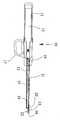
도 1a 은 본 발명 실시예의 장치의 측면 부분 절개도이다. 이 도면은 개방 위치에서의 클램프를 가진 장치와 수축 위치에서의 기계적 절개 도구를 도시한 것이다.1A is a side partial cutaway view of an apparatus of an embodiment of the present invention. This figure shows a device with a clamp in the open position and a mechanical incision tool in the retracted position.
도 1b 는 본 발명 실시예의 장치의 측면 부분 절개도이다. 이 도면은 폐쇄 위치에서의 클램프를 가진 장치와 수축 위치에서의 기계적 절개 도구를 도시한 것이다.1B is a side partial cutaway view of the apparatus of the embodiment of the present invention. This figure shows a device with a clamp in the closed position and a mechanical incision tool in the retracted position.
도 1c 는 본 발명 실시예의 장치의 측면 부분 절개도이다. 이 도면은 절개를 위한 향상된 위치에서의 클램프를 가진 장치와 수축 위치에서의 기계적 절개 도구를 도시한 것,1C is a side partial cutaway view of a device of an embodiment of the present invention. This figure shows a device with a clamp in an improved position for incision and a mechanical incision tool in a retracted position,
도 2 는 전자 어플리케이터, 클램프 및 기계적 절개도구를 포함하는 초음파 장치의 원거리 위치의 측면부 부분 절개도,2 is a partial cutaway side view of a remote location of an ultrasound device including an electronic applicator, a clamp and a mechanical incision;
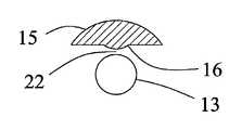
도 3a 는 상기 폐쇄 위치에서 오목면을 가진 클램프를 보여주는 초음파 장치의 말단부 평면도,3A is a plan view of the distal end of an ultrasound device showing a clamp having a concave surface in the closed position;
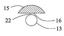
도 3b 는 상기 폐쇄 위치에서 볼록면을 가진 클램프를 보여주는 초음파 장치의 말단부 평면도,3b is an end plan view of the ultrasonic device showing the clamp with convex surface in the closed position;
도 3c 는 상기 폐쇄 위치에서 평탄면을 가진 클램프를 보여주는 초음파 장치의 말단부 평면도,3c is an end plan view of the ultrasonic device showing the clamp with the flat surface in the closed position;
도 4 는 본 발명 실시예의 장치의 측면부 부분 절개도로서, 공차 공차를 결정하는 정지 부재가 상기 초음파 장치의 핸들에 설치된 모습을 도시한 도면이다.Fig. 4 is a partial cutaway view of the apparatus of the embodiment of the present invention, showing a state in which a stop member for determining a tolerance is installed on a handle of the ultrasonic apparatus.
통상적인 참조 부호는 모든 도면상에서 이용되었다.Conventional reference numerals have been used on all figures.
도 1a 은 본 발명 실시예의 장치의 측면 부분 절개도이다. 도 1 은 일반적으로 설계되는 초음파 수술 도구(10)를 포함한 본 발명의 부분 절개도를 도시한 것이다. 상기 수술 도구는 외과 의사가 잡고 조작하는 수술 손잡이(11)를 가지고 있다. 상기 수술 손잡이(11)는 기계 가공 또는 몰딩된 합성수지 재료로부터 만들어질 수 있다. 초음파 변환기(12)는 초음파 진동을 발생시키기 위하여 상기 수술 손잡이(11) 내부에 설치되어 있다. 상기 초음파 진동은 압축된 상태에 놓여있는 PZT 크리스털과 같은 여타의 공지 공용 수단을 이용하여 발생시켜도 된다.1A is a side partial cutaway view of an apparatus of an embodiment of the present invention. 1 shows a partial cutaway view of the present invention including a generally designed ultrasound
초음파 어플리케이터(13)은 상기 초음파 변환기(12)에 부착되고 상기 초음파 변환기(12)의 외측으로 연장된다. 부착 방법은 나사 결합이 바람직하다. 상기 초음파 어플리케이터는 예를 들어 티타늄 합금, 알미늄 합금 또는 스테인레스 합금과 같이 여하한 적합한 금속 재료로서 만들어질 수 있으며, 티타늄 합금 Ti6A14V 가 바람직하고, 선반이나 밀링과 같은 표준적인 가공 공정이 이용될 수 있다.An
전술한 바와 같이, 본 발명에 채용된 초음파 어플리케이터는 조직에 대한 에너지의 주입을 고려하여 통상적으로 단면이 원형으로 되어 있다. 이들 어플리케이터는 조직의 절개를 진작시키기 위하여 초음파 에너지를 집중시키고 전이시킬 모서리 날을 갖지 않는 대신, 오로지 조직의 응고를 안정적으로 수행하기 위하여 에너지를 일정하게 제공하기 위한 목적으로 설계된다. 만일 절개 기능이 필요하다면 상기 초음파 어플리케이터의 설계 방법을 훼손하는 것을 피하기 위하여 별도로 수술 도구용 기계 요소가 제공되어 진다.As described above, the ultrasonic applicator employed in the present invention is typically circular in cross section in consideration of the injection of energy into the tissue. These applicators are designed for the purpose of providing a constant energy to reliably perform coagulation of the tissue instead of having no edge blades to concentrate and transfer the ultrasound energy to incite tissue incision. If an incision is required, mechanical components for surgical instruments are provided separately to avoid compromising the design method of the ultrasonic applicator.
상기 초음파 변환기(12) 및 상기 초음파 어플리케이터(13)의 전체 길이는 반드시 요구되는 진동의 공진 주파수를 가지도록 설계되어야 한다. 진동 주파수의 범위는 일반적으로 20 KHz 내지 60 KHz 이고, 이 범위에서 어떠한 진동 주파수도 이용될 수 있다.The overall length of the
연장 지지부(14)는 상기 수술 손잡이(11)에 부착되어 연장되어 있고, 일반적으로 상기 초음파 어플리케이터(13)의 길이에 맞추어 이를 둘러싸고 있다. 상기 연장 지지부(14)는 금속 또는 합성수지 재료로서 만들어질 수 있고, DelrinR(아세틸 코폴리머) 또는 "ABS"(아크릴로니트릴-부타딘-스티렌)과 같은 합성수지재가 바람직하다. 턱면(16)을 가지고 있는 클램프(15)는 상기 연장지지부(14)의 말단부에 부착되어 있다. 상기 클램프는 표준적인 가공 공정 또는 표준적인 몰딩 공정(금속 또는 플라스틱)을 이용하여 금속 또는 합성수지재로서 만들어질 수 있다. 바람직한 방법 및 재료로서는 몰딩된 금속 클램프 구조가 좋으며 그럼으로써 최대의 고정성과 가 장 좋은 클램핑 성능을 제공할 수 있다. 상기 턱면(16)은 예를 들어 도 3a 내지 도 3c 에 도시된 바와 같은 다양한 단면 형태를 가질 수 있다. 또한, 상기 턱면(16)은 쥐는 성능을 향상시키기 위하여 톱니 모양 또는 홈 모양의 표면을 가질 수 있다.The
상기 클램프(15)는 상기 초음파 어플리케이터(13)에 대하여 닫혀지거나 열려질 수 있다. 도 1a 은 상기 클램프가 열려진 위치를 도시한 것이다. 작동 손잡이(17)가 상기 수술 손잡이(11)에 부착되어 있고 그것은 상기 클램프(15)를 개방과 폐쇄 위치로 조작하는데 이용된다. 클램프 전달봉(18)은 상기 작동 손잡이(17)와 상기 클램프(15)를 연결한다.The
작동 슬라이더(19)는 상기 수술 손잡이(11)에 연결되고 이것은 절개 요소(20)를 평행한 방향 또는 일반적으로 상기 초음파 어플리케이터에 평행한 방향으로 전진시키거나 후퇴시키는데 이용된다. 상기 절개 요소(20)는 스테인레스 강철날 또는 날 연결봉(21)의 말단상에 형성된 절개면 형상일 수 있다. 상기 날 연결봉(21)은 상기 작동 슬라이더(19)와 상기 절개 요소(20)를 연결한다. 상기 날 연결봉(21)은 상기 절개 요소(20)에 납땜되거나 용접될 수 있는 스테인레스 강철선으로 제조되는 것이 바람직하다.An
도 2 는 도 1a 에 도시된 초음파 수술 도구(10)의 말단부의 측면 상세도로서, 상기 초음파 어플리케이터(13)에 대하여 개방 위치에 있는 클램프(15)와 이와 연동된 턱면(16)을 나타낸 것이다. 상기 클램프 집합체(30)의 표면(32)은 상기 연장지지부(14)의 표면(31)으로부터 분리되어 있다. 날 연결봉(21)에 부착되어 있는 상기 기계적 절개 도구 또는 날(20)이 후퇴된 위치에 놓여 있다. 상기 절개요소 (20)는 응고된 조직을 절개하기 위하여 상기 턱면(16)과 초음파 어플리케이터(13) 사이를 전진할 수 있다(도 1c 참조). 그러므로, 상기 절개 요소(20)는 상기 턱면(16)과 초음파 어플리케이터(13) 사이의 공차를 통하여 전진되거나 후퇴된다. 다른 실시예에서는, 상기 클램프(15)와 상기 턱면(16)은 연장되거나 후퇴되면서 통과하는 날의 모서리를 가진 수직의 슬롯을 가질 수 있다. 이로 인하여 더욱 넓은 범위의 기계적 절개 요소의 채용이 허용되고, 날에 의한 상기 턱면과 초음파 어플리케이터 사이의 공간에 놓여진 모든 조직의 절개를 공고하게 한다. 도 1b 는 작동 손잡이(17)가 폐쇄 위치로 회동되어 있다는 점을 제외하고 도 1a 에 도시된 동일한 초음파 수술 도구(10)를 도시한 것으로서, 상기 작동 손잡이의 회동에 의하여 상기 클램프 전달봉(18)이 상기 초음파 변환기(12) 방향으로 끌어당겨지고, 그럼으로써 상기 클램프(15)가 회동되어 상기 초음파 어플리케이터(13)를 폐쇄한 모습을 도시한 것이다. 클램프 전달봉(18)의 움직임은 상기 연장지지부(14)의 표면(31)에서 시작하여 클램프 하우징(30)의 표면(32)에 접촉되어 정지함으로써 제한된다. 그럼으로써 상기 클램프(15)의 턱면(16)이 공차 거리 또는 초음파 어플리케이터(13)의 표면으로부터의 공차에서 "폐쇄"된다(도 3a 내지 도 3c 참조). 상기 거리는 미리 결정될 수 있고 상기 클램프 전달봉(18)의 길이를 조절함으로써 변동될 수 있다. 환자로부터 수술 도구를 제거하는 일이 없이 상기 길이를 변동할 수 있도록 하기 위하여 해당 업계의 기술 수준 범위에 있는 물리 학자 또는 외과 과정의 의사에 의하여 그 수단을 제공받을 수 있다. 예를 들어, 상기 클램프 지지대(30)로부터 상기 작동 손잡이(17)까지의 클램프 전달봉의 유효 길이는 상기 수술 손잡이(11) 부분에 장착된 회동되는 전달봉을 사용함에 의하여 변동될 수 있다. 도 1b 에는 상기 절개 날 또는 도구(20)가 후퇴된 상태의 모습을 도시하였다.FIG. 2 is a side detail view of the distal end of the ultrasound
도 1c 는 도 1 에 도시된 상기 초음파 수술 도구(10)가 상기 연장된 위치에서 절개 날(20) 및 폐쇄된 위치에서의 클램프를 도시한 것이다. 이것은 상기 초음파 수술 도구의 말단 방향으로 작동 슬라이더(10)가 움직여서 그것에 의하여 상기 날 연결봉(21) 및 날(20)이 같은 방향으로 움직여서 달성된다. 이러한 것에 의하여 상기 클램프(15)와 초음파 어플리케이터(13) 사이에 놓여진 조직이 상기 날(20)에 의하여 절개된다.FIG. 1C shows the
도 3a 내지 도 3c 는 상기 턱면 및 사전 공차의 서로 다른 세가지 구조를 보여주는 도면이다.3A to 3C show three different structures of the jaw face and the pre-tolerance.
도 3a 는 최대한 "폐쇄"된 위치에서 상기 초음파 어플리케이터(13)의 말단 및 상기 연장지지부(14)와 클램프(15)를 도시한 것이다. 턱면(16)과 초음파 어플리케이터(13) 사이에서 조직의 응고의 깊이를 더욱 향상시키기 위하여 턱면(16)은 오목하게 형성된다. 상기 클램프(15)가 그것의 최대 길이로서 폐쇄되었을 때, 사전 공차(22)는 턱면(16)과 초음파 어플리케이터(13) 사이의 공간에 위치하고 통상적으로 약 0.075 mm 내지 약 1.9 mm, 바람직하게는 약 0.075 mm 내지 약 0.75 mm 의 길이를 가진다. 상기 공차 공차의 적정 수치는 의도되는 응용 분야에 따라 변동될 것이다.3A shows the distal end of the
도 3b 는 최대한 폐쇄된 위치에서 상기 초음파 어플리케이터(13)의 말단 및 상기 연장지지부(14)와 클램프(15)를 도시한 것이다. 말단에서 미응고 상태의 조직 에 보다 향상된 전이 상태를 가진 상태에서 조직의 응고 깊이를 감소시키기 위하여 턱면(16)은 볼록하다. 상기 클램프(15)가 최대로 폐쇄되었을 때, 사전 공차(22)는 턱면(16)과 초음파 어플리케이터(13) 사이의 공간에 위치하고 통상적으로 약 0.075 mm 내지 약 1.9 mm, 바람직하게는 약 0.075 mm 내지 약 0.75 mm 의 길이를 가진다. 상기 사전 공차의 적정 수치는 의도되는 응용 분야에 따라 변동될 것이다.3b shows the distal end of the
도 3c 는 최대한 폐쇄된 위치에서 상기 초음파 어플리케이터(13)의 말단 및 상기 연장지지부(14)와 클램프(15)를 도시한 것이다. 도 2a 및 도 2b 에 도시된 형상으로부터 획득된 결과를 조화시키기 위하여 턱면(16)이 평평하다. 상기 클램프(15)가 최대로 폐쇄되었을 때, 사전 공차(22)는 턱면(16)과 초음파 어플리케이터(13) 사이의 공간에 위치하고 통상적으로 약 0.075 mm 내지 약 1.9 mm, 바람직하게는 약 0.075 mm 내지 약 0.75 mm 의 길이를 가진다. 상기 공차의 적정 수치는 의도되는 응용 분야에 따라 변동될 것이다.3c shows the distal end of the
클램프(15)의 턱면(16)과 초음파 어플리케이터(13) 사이의 사전 공차는 여러가지의 방법으로 이루어진다. 이것은 도 1a 내지 도 1c 및 도 2 에 도시된 바와 같이, 지지부의 표면(31)에 대응하는 클램프 하우징의 표면(32)으로부터 비롯된 정지에 의하여 결정된다. 다른 기계적인 정지도 이용될 수 있다. 그러한 것에 하나가 도 1a 에서의 초음파 수술 도구를 도시한 도 4 에 도시된 정지 방법이다. 하지만, 이러한 경우에는 상기 정지는 상기 수술 손잡이(11)로부터 연장된 정지 부재(26)이고, 상기 하우징에 대하여 작동 손잡이(17)의 폐쇄를 막는다. 이것은 표면(31)에 접촉하는 것을 대신하고, 정지 메커니즘으로서 작용한다. 당업자는 가능한 유효 정 지 길이를 어떻게 만들것인가를 인지하고 있고, 그럼으로써 턱면과 어플리케이터 사이의 공차(22) 또한 변동된다. 예를 들면, 상기 정지 부재(26)는 상기 수술 손잡이(11) 내의 구멍으로 제한된 범위내에서 회동하고, 그럼으로써 사전 공차를 요구되는 길이만큼 효과적으로 늘리거나 줄일수 있다. 상기 턱면(16)과 초음파 어플리케이터(13) 사이의 사전 공차를 결정하는 다른 기술로서 해당 업계에 알려진 기술이 있을 수 있고, 그러한 것들은 여기에 기술된 실시예를 대치할 수 있다.Preliminary tolerances between the
또한, 본 발명은 (a) 응고를 위한 폭이 있는 구역을 제공하고 동물 조직의 절개를 피하기 위하여 대략 2 mm 내지 6 mm 사이의 지름을 가지는 원형 단면을 가지는 초음파 어플리케이터와 (b) 상기 초음파 어플리케이터의 근처에 위치되는 클램프 사이의 동물 조직 부분에 위치하는 동물 조직의 외과적 응고를 위한 더욱 향상된 방법을 제공한다. 그러면, 상기 클램프는 조직의 유동(flow)과 응고를 위한 구역을 제공하는 상기 초음파 어플리케이터로부터 대략 0.075 mm 내지 대략 1.9 mm 사이, 바람직하게는 대략 0.075 mm 내지 대략 0.75 mm 사이의 사전 공차를 가지고 움직이게 된다. 초음파 진동은 초음파 어플리케이터를 통하여 조직의 응고를 일으키기에 충분할 만큼 클램핑된 조직에 전달된다. 그러면, 목적된 조직은 여기에 도시된 도면 및 설명에서 기술한 바와 같이 개별적인 기계적 절삭 도구를 가지고 조직을 절개할 수 있게 된다.In addition, the present invention relates to an ultrasonic applicator having a circular cross section having a diameter between approximately 2 mm and 6 mm to provide a wide area for coagulation and to avoid incision of animal tissue, and (b) the ultrasonic applicator. It provides a further improved method for surgical coagulation of animal tissue located in portions of animal tissue between clamps located nearby. The clamp is then moved with a pre-tolerance between about 0.075 mm and about 1.9 mm, preferably between about 0.075 mm and about 0.75 mm, from the ultrasonic applicator providing a zone for flow and coagulation of tissue. . Ultrasonic vibrations are transmitted through the ultrasonic applicator to the clamped tissues sufficient to cause tissue coagulation. The tissue of interest can then be incised with a separate mechanical cutting tool as described in the figures and descriptions shown herein.
한편, 본 명세서에 개시된 본 발명의 실시예들은 이해를 돕기 위해 특정 예를 제시한 것에 지나지 않으며, 본 발명의 범위를 한정하고자 하는 것은 아니다. 여기에 개시된 실시예들 이외에도 본 발명의 기술적 사상에 바탕을 둔 다른 변형예 들이 실시 가능하다는 것은, 본 발명이 속하는 기술분야에서 통상의 지식을 가진 자에게 자명한 것이다.On the other hand, the embodiments of the present invention disclosed herein are not intended to limit the scope of the present invention only presented a specific example to facilitate understanding. It will be apparent to those skilled in the art that other modifications based on the technical idea of the present invention can be implemented in addition to the embodiments disclosed herein.
전술한 바와 같이 본 발명의 장치 및 방법은 특히 봉합과 절개 기능을 각각 분리시키거나 최대화시키는데 유용하다. 또한, 본 발명은 외과의에게 언제든지 상기 초음파 어플리케이터에 대한 클램프의 위치 및 상기 절개 요소 또는 절개날의 위치를 인지하기 위한 용이한 방법을 제공한다. 그러므로, 이러한 수술을 시행함에 있어서 의사는 보다 용이한 관찰과 집중을 할 수 있게 된다.As noted above, the devices and methods of the present invention are particularly useful for separating or maximizing suture and incision functions, respectively. In addition, the present invention provides a surgeon with an easy way to know the position of the clamp relative to the ultrasound applicator and the location of the incision element or incision blade at any time. Therefore, in performing such an operation, the doctor can easily observe and concentrate.
Claims (26)
Translated fromKoreanApplications Claiming Priority (2)
| Application Number | Priority Date | Filing Date | Title |
|---|---|---|---|
| US38611902P | 2002-06-04 | 2002-06-04 | |
| US60/386,119 | 2002-06-04 |
Publications (2)
| Publication Number | Publication Date |
|---|---|
| KR20050023291A KR20050023291A (en) | 2005-03-09 |
| KR101215983B1true KR101215983B1 (en) | 2012-12-27 |
Family
ID=29712231
Family Applications (1)
| Application Number | Title | Priority Date | Filing Date |
|---|---|---|---|
| KR1020047019797AExpired - Fee RelatedKR101215983B1 (en) | 2002-06-04 | 2003-06-04 | Ultrasonic device and method for tissue coagulation |
Country Status (11)
| Country | Link |
|---|---|
| US (2) | US7361172B2 (en) |
| EP (1) | EP1551321B1 (en) |
| KR (1) | KR101215983B1 (en) |
| CN (1) | CN100502979C (en) |
| AT (1) | ATE528046T1 (en) |
| AU (2) | AU2003237398B2 (en) |
| BR (1) | BR0311624A (en) |
| CA (1) | CA2488290C (en) |
| ES (1) | ES2373946T3 (en) |
| MX (1) | MXPA04012165A (en) |
| WO (1) | WO2003101531A2 (en) |
Cited By (1)
| Publication number | Priority date | Publication date | Assignee | Title |
|---|---|---|---|---|
| KR20160107586A (en) | 2015-03-04 | 2016-09-19 | 이메드 주식회사 | Ultrasonic Wave Surgery Apparatus Having Slanting Tissue Pad |
Families Citing this family (138)
| Publication number | Priority date | Publication date | Assignee | Title |
|---|---|---|---|---|
| US7364577B2 (en) | 2002-02-11 | 2008-04-29 | Sherwood Services Ag | Vessel sealing system |
| ES2262639T3 (en) | 2001-04-06 | 2006-12-01 | Sherwood Services Ag | SHUTTER AND DIVIDER OF GLASSES WITH BUMPER MEMBERS N OCONDUCTIVES. |
| US11229472B2 (en) | 2001-06-12 | 2022-01-25 | Cilag Gmbh International | Modular battery powered handheld surgical instrument with multiple magnetic position sensors |
| ATE528046T1 (en) | 2002-06-04 | 2011-10-15 | Sound Surgical Technologies Llc | ULTRASONIC DEVICE FOR TISSUE COAGULATION |
| US7367976B2 (en) | 2003-11-17 | 2008-05-06 | Sherwood Services Ag | Bipolar forceps having monopolar extension |
| US8182501B2 (en)* | 2004-02-27 | 2012-05-22 | Ethicon Endo-Surgery, Inc. | Ultrasonic surgical shears and method for sealing a blood vessel using same |
| US20060079879A1 (en) | 2004-10-08 | 2006-04-13 | Faller Craig N | Actuation mechanism for use with an ultrasonic surgical instrument |
| JP4402629B2 (en)* | 2005-08-19 | 2010-01-20 | オリンパスメディカルシステムズ株式会社 | Ultrasonic coagulation and incision device |
| US20070191713A1 (en) | 2005-10-14 | 2007-08-16 | Eichmann Stephen E | Ultrasonic device for cutting and coagulating |
| US20070167965A1 (en)* | 2006-01-05 | 2007-07-19 | Ethicon Endo-Surgery, Inc. | Ultrasonic medical instrument |
| US7621930B2 (en) | 2006-01-20 | 2009-11-24 | Ethicon Endo-Surgery, Inc. | Ultrasound medical instrument having a medical ultrasonic blade |
| US20070173872A1 (en)* | 2006-01-23 | 2007-07-26 | Ethicon Endo-Surgery, Inc. | Surgical instrument for cutting and coagulating patient tissue |
| US20070191712A1 (en)* | 2006-02-15 | 2007-08-16 | Ethicon Endo-Surgery, Inc. | Method for sealing a blood vessel, a medical system and a medical instrument |
| US7645278B2 (en)* | 2006-02-22 | 2010-01-12 | Olympus Corporation | Coagulating cutter |
| US20080200835A1 (en)* | 2006-06-30 | 2008-08-21 | Monson Gavin M | Energy Biopsy Device for Tissue Penetration and Hemostasis |
| US8911460B2 (en) | 2007-03-22 | 2014-12-16 | Ethicon Endo-Surgery, Inc. | Ultrasonic surgical instruments |
| US8057498B2 (en) | 2007-11-30 | 2011-11-15 | Ethicon Endo-Surgery, Inc. | Ultrasonic surgical instrument blades |
| US8142461B2 (en) | 2007-03-22 | 2012-03-27 | Ethicon Endo-Surgery, Inc. | Surgical instruments |
| US8808319B2 (en) | 2007-07-27 | 2014-08-19 | Ethicon Endo-Surgery, Inc. | Surgical instruments |
| US8523889B2 (en) | 2007-07-27 | 2013-09-03 | Ethicon Endo-Surgery, Inc. | Ultrasonic end effectors with increased active length |
| US9044261B2 (en) | 2007-07-31 | 2015-06-02 | Ethicon Endo-Surgery, Inc. | Temperature controlled ultrasonic surgical instruments |
| US8512365B2 (en) | 2007-07-31 | 2013-08-20 | Ethicon Endo-Surgery, Inc. | Surgical instruments |
| US8430898B2 (en) | 2007-07-31 | 2013-04-30 | Ethicon Endo-Surgery, Inc. | Ultrasonic surgical instruments |
| US7955275B2 (en)* | 2007-08-28 | 2011-06-07 | Ferzli George S | Laparoscopic instrument and method for distance measurements of body parts |
| EP2217157A2 (en) | 2007-10-05 | 2010-08-18 | Ethicon Endo-Surgery, Inc. | Ergonomic surgical instruments |
| US10010339B2 (en) | 2007-11-30 | 2018-07-03 | Ethicon Llc | Ultrasonic surgical blades |
| US9089360B2 (en) | 2008-08-06 | 2015-07-28 | Ethicon Endo-Surgery, Inc. | Devices and techniques for cutting and coagulating tissue |
| US8142473B2 (en) | 2008-10-03 | 2012-03-27 | Tyco Healthcare Group Lp | Method of transferring rotational motion in an articulating surgical instrument |
| US8444642B2 (en)* | 2009-04-03 | 2013-05-21 | Device Evolutions, Llc | Laparoscopic nephrectomy device |
| US9700339B2 (en) | 2009-05-20 | 2017-07-11 | Ethicon Endo-Surgery, Inc. | Coupling arrangements and methods for attaching tools to ultrasonic surgical instruments |
| US8246618B2 (en) | 2009-07-08 | 2012-08-21 | Tyco Healthcare Group Lp | Electrosurgical jaws with offset knife |
| US8663220B2 (en) | 2009-07-15 | 2014-03-04 | Ethicon Endo-Surgery, Inc. | Ultrasonic surgical instruments |
| USRE47996E1 (en) | 2009-10-09 | 2020-05-19 | Ethicon Llc | Surgical generator for ultrasonic and electrosurgical devices |
| US11090104B2 (en) | 2009-10-09 | 2021-08-17 | Cilag Gmbh International | Surgical generator for ultrasonic and electrosurgical devices |
| US10441345B2 (en) | 2009-10-09 | 2019-10-15 | Ethicon Llc | Surgical generator for ultrasonic and electrosurgical devices |
| US9050093B2 (en) | 2009-10-09 | 2015-06-09 | Ethicon Endo-Surgery, Inc. | Surgical generator for ultrasonic and electrosurgical devices |
| US8388647B2 (en)* | 2009-10-28 | 2013-03-05 | Covidien Lp | Apparatus for tissue sealing |
| US8486096B2 (en) | 2010-02-11 | 2013-07-16 | Ethicon Endo-Surgery, Inc. | Dual purpose surgical instrument for cutting and coagulating tissue |
| US8469981B2 (en) | 2010-02-11 | 2013-06-25 | Ethicon Endo-Surgery, Inc. | Rotatable cutting implement arrangements for ultrasonic surgical instruments |
| US8951272B2 (en) | 2010-02-11 | 2015-02-10 | Ethicon Endo-Surgery, Inc. | Seal arrangements for ultrasonically powered surgical instruments |
| US8795327B2 (en) | 2010-07-22 | 2014-08-05 | Ethicon Endo-Surgery, Inc. | Electrosurgical instrument with separate closure and cutting members |
| US9192431B2 (en) | 2010-07-23 | 2015-11-24 | Ethicon Endo-Surgery, Inc. | Electrosurgical cutting and sealing instrument |
| US9113940B2 (en) | 2011-01-14 | 2015-08-25 | Covidien Lp | Trigger lockout and kickback mechanism for surgical instruments |
| US9259265B2 (en) | 2011-07-22 | 2016-02-16 | Ethicon Endo-Surgery, Llc | Surgical instruments for tensioning tissue |
| USD680220S1 (en) | 2012-01-12 | 2013-04-16 | Coviden IP | Slider handle for laparoscopic device |
| WO2013119545A1 (en) | 2012-02-10 | 2013-08-15 | Ethicon-Endo Surgery, Inc. | Robotically controlled surgical instrument |
| US9439668B2 (en) | 2012-04-09 | 2016-09-13 | Ethicon Endo-Surgery, Llc | Switch arrangements for ultrasonic surgical instruments |
| US20140005705A1 (en) | 2012-06-29 | 2014-01-02 | Ethicon Endo-Surgery, Inc. | Surgical instruments with articulating shafts |
| US9393037B2 (en) | 2012-06-29 | 2016-07-19 | Ethicon Endo-Surgery, Llc | Surgical instruments with articulating shafts |
| US20140005702A1 (en) | 2012-06-29 | 2014-01-02 | Ethicon Endo-Surgery, Inc. | Ultrasonic surgical instruments with distally positioned transducers |
| US9408622B2 (en) | 2012-06-29 | 2016-08-09 | Ethicon Endo-Surgery, Llc | Surgical instruments with articulating shafts |
| US9326788B2 (en) | 2012-06-29 | 2016-05-03 | Ethicon Endo-Surgery, Llc | Lockout mechanism for use with robotic electrosurgical device |
| US9820768B2 (en) | 2012-06-29 | 2017-11-21 | Ethicon Llc | Ultrasonic surgical instruments with control mechanisms |
| US9226767B2 (en) | 2012-06-29 | 2016-01-05 | Ethicon Endo-Surgery, Inc. | Closed feedback control for electrosurgical device |
| US9351754B2 (en) | 2012-06-29 | 2016-05-31 | Ethicon Endo-Surgery, Llc | Ultrasonic surgical instruments with distally positioned jaw assemblies |
| US9198714B2 (en) | 2012-06-29 | 2015-12-01 | Ethicon Endo-Surgery, Inc. | Haptic feedback devices for surgical robot |
| EP2900158B1 (en) | 2012-09-28 | 2020-04-15 | Ethicon LLC | Multi-function bi-polar forceps |
| US9095367B2 (en) | 2012-10-22 | 2015-08-04 | Ethicon Endo-Surgery, Inc. | Flexible harmonic waveguides/blades for surgical instruments |
| US20140135804A1 (en) | 2012-11-15 | 2014-05-15 | Ethicon Endo-Surgery, Inc. | Ultrasonic and electrosurgical devices |
| US10226273B2 (en) | 2013-03-14 | 2019-03-12 | Ethicon Llc | Mechanical fasteners for use with surgical energy devices |
| US9814514B2 (en) | 2013-09-13 | 2017-11-14 | Ethicon Llc | Electrosurgical (RF) medical instruments for cutting and coagulating tissue |
| US9265926B2 (en) | 2013-11-08 | 2016-02-23 | Ethicon Endo-Surgery, Llc | Electrosurgical devices |
| GB2521229A (en) | 2013-12-16 | 2015-06-17 | Ethicon Endo Surgery Inc | Medical device |
| GB2521228A (en) | 2013-12-16 | 2015-06-17 | Ethicon Endo Surgery Inc | Medical device |
| US9795436B2 (en) | 2014-01-07 | 2017-10-24 | Ethicon Llc | Harvesting energy from a surgical generator |
| US9554854B2 (en) | 2014-03-18 | 2017-01-31 | Ethicon Endo-Surgery, Llc | Detecting short circuits in electrosurgical medical devices |
| US10092310B2 (en) | 2014-03-27 | 2018-10-09 | Ethicon Llc | Electrosurgical devices |
| US10463421B2 (en) | 2014-03-27 | 2019-11-05 | Ethicon Llc | Two stage trigger, clamp and cut bipolar vessel sealer |
| US9737355B2 (en) | 2014-03-31 | 2017-08-22 | Ethicon Llc | Controlling impedance rise in electrosurgical medical devices |
| US9913680B2 (en) | 2014-04-15 | 2018-03-13 | Ethicon Llc | Software algorithms for electrosurgical instruments |
| US10285724B2 (en) | 2014-07-31 | 2019-05-14 | Ethicon Llc | Actuation mechanisms and load adjustment assemblies for surgical instruments |
| US10639092B2 (en) | 2014-12-08 | 2020-05-05 | Ethicon Llc | Electrode configurations for surgical instruments |
| US10245095B2 (en) | 2015-02-06 | 2019-04-02 | Ethicon Llc | Electrosurgical instrument with rotation and articulation mechanisms |
| US10321950B2 (en) | 2015-03-17 | 2019-06-18 | Ethicon Llc | Managing tissue treatment |
| US10342602B2 (en) | 2015-03-17 | 2019-07-09 | Ethicon Llc | Managing tissue treatment |
| US10595929B2 (en) | 2015-03-24 | 2020-03-24 | Ethicon Llc | Surgical instruments with firing system overload protection mechanisms |
| US10034684B2 (en) | 2015-06-15 | 2018-07-31 | Ethicon Llc | Apparatus and method for dissecting and coagulating tissue |
| US11020140B2 (en) | 2015-06-17 | 2021-06-01 | Cilag Gmbh International | Ultrasonic surgical blade for use with ultrasonic surgical instruments |
| US10357303B2 (en) | 2015-06-30 | 2019-07-23 | Ethicon Llc | Translatable outer tube for sealing using shielded lap chole dissector |
| US11129669B2 (en) | 2015-06-30 | 2021-09-28 | Cilag Gmbh International | Surgical system with user adaptable techniques based on tissue type |
| US10898256B2 (en) | 2015-06-30 | 2021-01-26 | Ethicon Llc | Surgical system with user adaptable techniques based on tissue impedance |
| US10034704B2 (en) | 2015-06-30 | 2018-07-31 | Ethicon Llc | Surgical instrument with user adaptable algorithms |
| US11051873B2 (en) | 2015-06-30 | 2021-07-06 | Cilag Gmbh International | Surgical system with user adaptable techniques employing multiple energy modalities based on tissue parameters |
| US11141213B2 (en) | 2015-06-30 | 2021-10-12 | Cilag Gmbh International | Surgical instrument with user adaptable techniques |
| US10154852B2 (en) | 2015-07-01 | 2018-12-18 | Ethicon Llc | Ultrasonic surgical blade with improved cutting and coagulation features |
| US10194973B2 (en) | 2015-09-30 | 2019-02-05 | Ethicon Llc | Generator for digitally generating electrical signal waveforms for electrosurgical and ultrasonic surgical instruments |
| US10595930B2 (en) | 2015-10-16 | 2020-03-24 | Ethicon Llc | Electrode wiping surgical device |
| US10179022B2 (en) | 2015-12-30 | 2019-01-15 | Ethicon Llc | Jaw position impedance limiter for electrosurgical instrument |
| US10575892B2 (en) | 2015-12-31 | 2020-03-03 | Ethicon Llc | Adapter for electrical surgical instruments |
| US11129670B2 (en) | 2016-01-15 | 2021-09-28 | Cilag Gmbh International | Modular battery powered handheld surgical instrument with selective application of energy based on button displacement, intensity, or local tissue characterization |
| US12193698B2 (en) | 2016-01-15 | 2025-01-14 | Cilag Gmbh International | Method for self-diagnosing operation of a control switch in a surgical instrument system |
| US11051840B2 (en) | 2016-01-15 | 2021-07-06 | Ethicon Llc | Modular battery powered handheld surgical instrument with reusable asymmetric handle housing |
| US11229471B2 (en) | 2016-01-15 | 2022-01-25 | Cilag Gmbh International | Modular battery powered handheld surgical instrument with selective application of energy based on tissue characterization |
| US10716615B2 (en) | 2016-01-15 | 2020-07-21 | Ethicon Llc | Modular battery powered handheld surgical instrument with curved end effectors having asymmetric engagement between jaw and blade |
| US10555769B2 (en) | 2016-02-22 | 2020-02-11 | Ethicon Llc | Flexible circuits for electrosurgical instrument |
| US10702329B2 (en) | 2016-04-29 | 2020-07-07 | Ethicon Llc | Jaw structure with distal post for electrosurgical instruments |
| US10485607B2 (en) | 2016-04-29 | 2019-11-26 | Ethicon Llc | Jaw structure with distal closure for electrosurgical instruments |
| US10646269B2 (en) | 2016-04-29 | 2020-05-12 | Ethicon Llc | Non-linear jaw gap for electrosurgical instruments |
| US10456193B2 (en) | 2016-05-03 | 2019-10-29 | Ethicon Llc | Medical device with a bilateral jaw configuration for nerve stimulation |
| US10245064B2 (en) | 2016-07-12 | 2019-04-02 | Ethicon Llc | Ultrasonic surgical instrument with piezoelectric central lumen transducer |
| US10893883B2 (en) | 2016-07-13 | 2021-01-19 | Ethicon Llc | Ultrasonic assembly for use with ultrasonic surgical instruments |
| US10842522B2 (en) | 2016-07-15 | 2020-11-24 | Ethicon Llc | Ultrasonic surgical instruments having offset blades |
| US10376305B2 (en) | 2016-08-05 | 2019-08-13 | Ethicon Llc | Methods and systems for advanced harmonic energy |
| US10285723B2 (en) | 2016-08-09 | 2019-05-14 | Ethicon Llc | Ultrasonic surgical blade with improved heel portion |
| USD847990S1 (en) | 2016-08-16 | 2019-05-07 | Ethicon Llc | Surgical instrument |
| US10736649B2 (en) | 2016-08-25 | 2020-08-11 | Ethicon Llc | Electrical and thermal connections for ultrasonic transducer |
| US10952759B2 (en) | 2016-08-25 | 2021-03-23 | Ethicon Llc | Tissue loading of a surgical instrument |
| US10603064B2 (en) | 2016-11-28 | 2020-03-31 | Ethicon Llc | Ultrasonic transducer |
| US11266430B2 (en) | 2016-11-29 | 2022-03-08 | Cilag Gmbh International | End effector control and calibration |
| CN106888833B (en)* | 2017-03-20 | 2021-04-20 | 中国水利水电科学研究院 | A crop ultrasonic guillotine knife and system |
| CN106857032B (en)* | 2017-03-20 | 2020-07-03 | 中国水利水电科学研究院 | Crop electrocoagulation root breaking knife and system |
| US10820920B2 (en) | 2017-07-05 | 2020-11-03 | Ethicon Llc | Reusable ultrasonic medical devices and methods of their use |
| US11452525B2 (en) | 2019-12-30 | 2022-09-27 | Cilag Gmbh International | Surgical instrument comprising an adjustment system |
| US12336747B2 (en) | 2019-12-30 | 2025-06-24 | Cilag Gmbh International | Method of operating a combination ultrasonic / bipolar RF surgical device with a combination energy modality end-effector |
| US11950797B2 (en) | 2019-12-30 | 2024-04-09 | Cilag Gmbh International | Deflectable electrode with higher distal bias relative to proximal bias |
| US11684412B2 (en) | 2019-12-30 | 2023-06-27 | Cilag Gmbh International | Surgical instrument with rotatable and articulatable surgical end effector |
| US11786291B2 (en) | 2019-12-30 | 2023-10-17 | Cilag Gmbh International | Deflectable support of RF energy electrode with respect to opposing ultrasonic blade |
| US12343063B2 (en) | 2019-12-30 | 2025-07-01 | Cilag Gmbh International | Multi-layer clamp arm pad for enhanced versatility and performance of a surgical device |
| US12076006B2 (en) | 2019-12-30 | 2024-09-03 | Cilag Gmbh International | Surgical instrument comprising an orientation detection system |
| US20210196357A1 (en) | 2019-12-30 | 2021-07-01 | Ethicon Llc | Electrosurgical instrument with asynchronous energizing electrodes |
| US12053224B2 (en) | 2019-12-30 | 2024-08-06 | Cilag Gmbh International | Variation in electrode parameters and deflectable electrode to modify energy density and tissue interaction |
| US11779329B2 (en) | 2019-12-30 | 2023-10-10 | Cilag Gmbh International | Surgical instrument comprising a flex circuit including a sensor system |
| US12023086B2 (en) | 2019-12-30 | 2024-07-02 | Cilag Gmbh International | Electrosurgical instrument for delivering blended energy modalities to tissue |
| US11696776B2 (en) | 2019-12-30 | 2023-07-11 | Cilag Gmbh International | Articulatable surgical instrument |
| US11812957B2 (en) | 2019-12-30 | 2023-11-14 | Cilag Gmbh International | Surgical instrument comprising a signal interference resolution system |
| US11779387B2 (en) | 2019-12-30 | 2023-10-10 | Cilag Gmbh International | Clamp arm jaw to minimize tissue sticking and improve tissue control |
| US12082808B2 (en) | 2019-12-30 | 2024-09-10 | Cilag Gmbh International | Surgical instrument comprising a control system responsive to software configurations |
| US11937863B2 (en) | 2019-12-30 | 2024-03-26 | Cilag Gmbh International | Deflectable electrode with variable compression bias along the length of the deflectable electrode |
| US20210196362A1 (en) | 2019-12-30 | 2021-07-01 | Ethicon Llc | Electrosurgical end effectors with thermally insulative and thermally conductive portions |
| US11786294B2 (en) | 2019-12-30 | 2023-10-17 | Cilag Gmbh International | Control program for modular combination energy device |
| US11986201B2 (en) | 2019-12-30 | 2024-05-21 | Cilag Gmbh International | Method for operating a surgical instrument |
| US11944366B2 (en) | 2019-12-30 | 2024-04-02 | Cilag Gmbh International | Asymmetric segmented ultrasonic support pad for cooperative engagement with a movable RF electrode |
| US12114912B2 (en) | 2019-12-30 | 2024-10-15 | Cilag Gmbh International | Non-biased deflectable electrode to minimize contact between ultrasonic blade and electrode |
| US11660089B2 (en) | 2019-12-30 | 2023-05-30 | Cilag Gmbh International | Surgical instrument comprising a sensing system |
| US11937866B2 (en) | 2019-12-30 | 2024-03-26 | Cilag Gmbh International | Method for an electrosurgical procedure |
| US12064109B2 (en) | 2019-12-30 | 2024-08-20 | Cilag Gmbh International | Surgical instrument comprising a feedback control circuit |
| US11911063B2 (en) | 2019-12-30 | 2024-02-27 | Cilag Gmbh International | Techniques for detecting ultrasonic blade to electrode contact and reducing power to ultrasonic blade |
| US12262937B2 (en) | 2019-12-30 | 2025-04-01 | Cilag Gmbh International | User interface for surgical instrument with combination energy modality end-effector |
Citations (4)
| Publication number | Priority date | Publication date | Assignee | Title |
|---|---|---|---|---|
| US5322055A (en)* | 1993-01-27 | 1994-06-21 | Ultracision, Inc. | Clamp coagulator/cutting system for ultrasonic surgical instruments |
| US6004335A (en)* | 1994-08-02 | 1999-12-21 | Ethicon Endo-Surgery, Inc. | Ultrasonic hemostatic and cutting instrument |
| US20030055417A1 (en) | 2001-09-19 | 2003-03-20 | Csaba Truckai | Surgical system for applying ultrasonic energy to tissue |
| US20080002380A1 (en)* | 2006-06-29 | 2008-01-03 | Peter Hazucha | Integrated inductor |
Family Cites Families (52)
| Publication number | Priority date | Publication date | Assignee | Title |
|---|---|---|---|---|
| DE7705947U1 (en) | 1900-01-01 | Storz, Karl, 7200 Tuttlingen | ||
| US2714890A (en)* | 1953-08-06 | 1955-08-09 | Vang Alfred | Vibratory surgical instruments |
| US2845072A (en)* | 1955-06-21 | 1958-07-29 | William A Shafer | Surgical knife |
| US3053124A (en)* | 1959-11-16 | 1962-09-11 | Cavitron Ultrasonics Inc | Ultrasonic welding |
| US3526219A (en)* | 1967-07-21 | 1970-09-01 | Ultrasonic Systems | Method and apparatus for ultrasonically removing tissue from a biological organism |
| US3636943A (en) | 1967-10-27 | 1972-01-25 | Ultrasonic Systems | Ultrasonic cauterization |
| US3657056A (en)* | 1967-12-11 | 1972-04-18 | Ultrasonic Systems | Ultrasonic suturing apparatus |
| DE2032501A1 (en) | 1970-07-01 | 1972-01-05 | Kloz, Eduard; Kloz, Heinz; 7211 Hausen | Device for rendering harmless preferably bladder, uretheric and renal pelvic stones |
| CH541958A (en)* | 1970-11-03 | 1973-09-30 | Eduard Kloz & Heinz Kloz | Device for smashing bladder, ureter and renal pelvic stones using ultrasound |
| US3752161A (en)* | 1971-08-02 | 1973-08-14 | Minnesota Mining & Mfg | Fluid operated surgical tool |
| US3899829A (en)* | 1974-02-07 | 1975-08-19 | Fred Storm Ind Designs Inc | Holder and actuator means for surgical instruments |
| FR2355521A1 (en) | 1976-06-22 | 1978-01-20 | Mendez Rene | Surgical forceps for biopsy and electro-coagulation - with insulation along complete tube length and over jaws to prevent random burning |
| SU737735A1 (en) | 1978-10-20 | 1980-05-30 | Новополоцкий политехнический институт | Apparatus for centrifugal spraying of solutions and suspensions |
| US4375961A (en)* | 1981-09-28 | 1983-03-08 | Brooks Phillip A | Sonic bonding means for orthodontics |
| US4491132A (en)* | 1982-08-06 | 1985-01-01 | Zimmer, Inc. | Sheath and retractable surgical tool combination |
| US4497320A (en)* | 1983-02-14 | 1985-02-05 | Rudolph Beaver, Inc. | Surgical blade unit |
| JPS61128954A (en) | 1984-11-28 | 1986-06-17 | オリンパス光学工業株式会社 | Forcept for endoscope and its production |
| US4655216A (en)* | 1985-07-23 | 1987-04-07 | Alfred Tischer | Combination instrument for laparoscopical tube sterilization |
| JPS6266848A (en)* | 1985-09-20 | 1987-03-26 | 住友ベークライト株式会社 | Surgical operation appliance |
| US4674500A (en)* | 1985-09-27 | 1987-06-23 | Minnesota Mining And Manufacturing Company | Sheathed knife instrument |
| US4723545A (en)* | 1986-02-03 | 1988-02-09 | Graduate Hospital Foundation Research Corporation | Power assisted arthroscopic surgical device |
| NL8602759A (en)* | 1986-10-31 | 1988-05-16 | Bekaert Sa Nv | METHOD AND DEVICE FOR TREATING AN LONG-TERM SUBSTRATE COVERED; AND SUBSTRATES TREATED ACCORDING TO THAT METHOD AND ARTICLES OF POLYMER MATERIAL REINFORCED WITH THESE SUBSTRATES. |
| US4733662A (en)* | 1987-01-20 | 1988-03-29 | Minnesota Mining And Manufacturing Company | Tissue gripping and cutting assembly for surgical instrument |
| US4825865A (en)* | 1987-05-01 | 1989-05-02 | Jerry Zelman | Apparatus and method for extracting cataract tissue |
| JP2592487B2 (en) | 1988-03-14 | 1997-03-19 | オリンパス光学工業株式会社 | Surgical resection forceps |
| US4877026A (en)* | 1988-07-22 | 1989-10-31 | Microline Inc. | Surgical apparatus |
| US5123903A (en)* | 1989-08-10 | 1992-06-23 | Medical Products Development, Inc. | Disposable aspiration sleeve for ultrasonic lipectomy |
| US5797939A (en)* | 1989-12-05 | 1998-08-25 | Yoon; Inbae | Endoscopic scissors with longitudinal operating channel |
| US5059210A (en)* | 1989-12-12 | 1991-10-22 | Ultracision Inc. | Apparatus and methods for attaching and detaching an ultrasonic actuated blade/coupler and an acoustical mount therefor |
| US5263957A (en)* | 1990-03-12 | 1993-11-23 | Ultracision Inc. | Ultrasonic scalpel blade and methods of application |
| US5167725A (en)* | 1990-08-01 | 1992-12-01 | Ultracision, Inc. | Titanium alloy blade coupler coated with nickel-chrome for ultrasonic scalpel |
| US5147357A (en)* | 1991-03-18 | 1992-09-15 | Rose Anthony T | Medical instrument |
| US5217460A (en)* | 1991-03-22 | 1993-06-08 | Knoepfler Dennis J | Multiple purpose forceps |
| US5201759A (en)* | 1991-04-29 | 1993-04-13 | Ferzli George S | Laparoscopic instrument |
| US5324299A (en)* | 1992-02-03 | 1994-06-28 | Ultracision, Inc. | Ultrasonic scalpel blade and methods of application |
| US6358264B2 (en)* | 1996-07-24 | 2002-03-19 | Surgical Design Corporation | Surgical instruments with movable member |
| US6036667A (en)* | 1996-10-04 | 2000-03-14 | United States Surgical Corporation | Ultrasonic dissection and coagulation system |
| US5984867A (en)* | 1997-05-02 | 1999-11-16 | Heartport, Inc. | Surgical retractor and method of retracting |
| US6024750A (en)* | 1997-08-14 | 2000-02-15 | United States Surgical | Ultrasonic curved blade |
| US5873873A (en)* | 1997-10-10 | 1999-02-23 | Ethicon Endo-Surgery, Inc. | Ultrasonic clamp coagulator apparatus having improved clamp mechanism |
| US6193709B1 (en) | 1998-05-13 | 2001-02-27 | Olympus Optical Co., Ltd. | Ultrasonic treatment apparatus |
| US6080175A (en)* | 1998-07-29 | 2000-06-27 | Corvascular, Inc. | Surgical cutting instrument and method of use |
| JP4164235B2 (en)* | 1998-10-23 | 2008-10-15 | コビディエン アクチェンゲゼルシャフト | Endoscopic bipolar electrosurgical forceps |
| US6569178B1 (en)* | 1999-03-09 | 2003-05-27 | Olympus Optical Co., Ltd. | Ultrasonic coagulating/cutting apparatus |
| US6325811B1 (en)* | 1999-10-05 | 2001-12-04 | Ethicon Endo-Surgery, Inc. | Blades with functional balance asymmetries for use with ultrasonic surgical instruments |
| JP4233742B2 (en)* | 1999-10-05 | 2009-03-04 | エシコン・エンド−サージェリィ・インコーポレイテッド | Connecting curved clamp arms and tissue pads used with ultrasonic surgical instruments |
| US6352532B1 (en)* | 1999-12-14 | 2002-03-05 | Ethicon Endo-Surgery, Inc. | Active load control of ultrasonic surgical instruments |
| BR0104246A (en)* | 2000-01-26 | 2002-05-21 | Heartport Inc | Vascular incisor and method |
| US6623423B2 (en)* | 2000-02-29 | 2003-09-23 | Olympus Optical Co., Ltd. | Surgical operation system |
| US6558376B2 (en)* | 2000-06-30 | 2003-05-06 | Gregory D. Bishop | Method of use of an ultrasonic clamp and coagulation apparatus with tissue support surface |
| US20020002380A1 (en)* | 2000-06-30 | 2002-01-03 | Bishop Gregory D. | Ultrasonic clamp and coagulation apparatus with tissue support surface |
| ATE528046T1 (en) | 2002-06-04 | 2011-10-15 | Sound Surgical Technologies Llc | ULTRASONIC DEVICE FOR TISSUE COAGULATION |
- 2003
- 2003-06-04ATAT03736854Tpatent/ATE528046T1/ennot_activeIP Right Cessation
- 2003-06-04EPEP03736854Apatent/EP1551321B1/ennot_activeExpired - Lifetime
- 2003-06-04USUS10/455,486patent/US7361172B2/ennot_activeExpired - Lifetime
- 2003-06-04WOPCT/US2003/017677patent/WO2003101531A2/ennot_activeApplication Discontinuation
- 2003-06-04KRKR1020047019797Apatent/KR101215983B1/ennot_activeExpired - Fee Related
- 2003-06-04CNCNB038187094Apatent/CN100502979C/ennot_activeExpired - Fee Related
- 2003-06-04BRBRPI0311624-7Apatent/BR0311624A/ennot_activeApplication Discontinuation
- 2003-06-04CACA2488290Apatent/CA2488290C/ennot_activeExpired - Fee Related
- 2003-06-04MXMXPA04012165Apatent/MXPA04012165A/enactiveIP Right Grant
- 2003-06-04AUAU2003237398Apatent/AU2003237398B2/ennot_activeCeased
- 2003-06-04ESES03736854Tpatent/ES2373946T3/ennot_activeExpired - Lifetime
- 2008
- 2008-04-22USUS12/107,663patent/US20080195004A1/ennot_activeAbandoned
- 2009
- 2009-06-16AUAU2009202406Apatent/AU2009202406A1/ennot_activeAbandoned
Patent Citations (5)
| Publication number | Priority date | Publication date | Assignee | Title |
|---|---|---|---|---|
| US5322055A (en)* | 1993-01-27 | 1994-06-21 | Ultracision, Inc. | Clamp coagulator/cutting system for ultrasonic surgical instruments |
| US5322055B1 (en)* | 1993-01-27 | 1997-10-14 | Ultracision Inc | Clamp coagulator/cutting system for ultrasonic surgical instruments |
| US6004335A (en)* | 1994-08-02 | 1999-12-21 | Ethicon Endo-Surgery, Inc. | Ultrasonic hemostatic and cutting instrument |
| US20030055417A1 (en) | 2001-09-19 | 2003-03-20 | Csaba Truckai | Surgical system for applying ultrasonic energy to tissue |
| US20080002380A1 (en)* | 2006-06-29 | 2008-01-03 | Peter Hazucha | Integrated inductor |
Cited By (1)
| Publication number | Priority date | Publication date | Assignee | Title |
|---|---|---|---|---|
| KR20160107586A (en) | 2015-03-04 | 2016-09-19 | 이메드 주식회사 | Ultrasonic Wave Surgery Apparatus Having Slanting Tissue Pad |
Also Published As
| Publication number | Publication date |
|---|---|
| KR20050023291A (en) | 2005-03-09 |
| CN100502979C (en) | 2009-06-24 |
| US20040102801A1 (en) | 2004-05-27 |
| EP1551321B1 (en) | 2011-10-12 |
| BR0311624A (en) | 2007-05-08 |
| WO2003101531A2 (en) | 2003-12-11 |
| US7361172B2 (en) | 2008-04-22 |
| AU2003237398A1 (en) | 2003-12-19 |
| AU2009202406A1 (en) | 2009-07-09 |
| ES2373946T3 (en) | 2012-02-10 |
| CA2488290C (en) | 2012-09-11 |
| MXPA04012165A (en) | 2005-04-19 |
| WO2003101531A3 (en) | 2004-03-18 |
| EP1551321A2 (en) | 2005-07-13 |
| CN1674835A (en) | 2005-09-28 |
| AU2003237398B2 (en) | 2009-07-09 |
| ATE528046T1 (en) | 2011-10-15 |
| CA2488290A1 (en) | 2003-12-11 |
| US20080195004A1 (en) | 2008-08-14 |
| EP1551321A4 (en) | 2007-11-14 |
| HK1083780A1 (en) | 2006-07-14 |
Similar Documents
| Publication | Publication Date | Title |
|---|---|---|
| KR101215983B1 (en) | Ultrasonic device and method for tissue coagulation | |
| US20250169844A1 (en) | Ultrasonic surgical blade for use with ultrasonic surgical instruments | |
| JP6271120B2 (en) | Ultrasonic equipment for cutting and coagulation | |
| US20080147092A1 (en) | Hybrid energy instrument combined with clip application capability | |
| US6117152A (en) | Multi-function ultrasonic surgical instrument | |
| Lee et al. | Ultrasonic energy in endoscopic surgery | |
| US20190083125A1 (en) | Tissue engagement apparatus for theapeutic ultrasound apparatus and method | |
| JP2008504849A (en) | Tissue cutting device | |
| JP3709226B2 (en) | Ultrasonic coagulation and incision device | |
| WO2016197348A1 (en) | Ultrasonic surgery device and end effector | |
| JP4422243B2 (en) | Ultrasonic treatment device | |
| JP2001037769A (en) | Ultrasonic treatment implement | |
| HK1083780B (en) | Ultrasonic device for tissue coagulation | |
| JP4229535B2 (en) | Surgical coagulation and hemostatic device | |
| KR20220063452A (en) | End effector of Ultrasound operating equipment | |
| JP2005074014A (en) | Trocar system | |
| Boni et al. | Transection Techniques in liver surgery | |
| JP2016055135A (en) | Ultrasonic coagulation device having roughened surface end effector blade |
Legal Events
| Date | Code | Title | Description |
|---|---|---|---|
| PA0105 | International application | St.27 status event code:A-0-1-A10-A15-nap-PA0105 | |
| T11-X000 | Administrative time limit extension requested | St.27 status event code:U-3-3-T10-T11-oth-X000 | |
| P11-X000 | Amendment of application requested | St.27 status event code:A-2-2-P10-P11-nap-X000 | |
| P13-X000 | Application amended | St.27 status event code:A-2-2-P10-P13-nap-X000 | |
| R18-X000 | Changes to party contact information recorded | St.27 status event code:A-3-3-R10-R18-oth-X000 | |
| PG1501 | Laying open of application | St.27 status event code:A-1-1-Q10-Q12-nap-PG1501 | |
| A201 | Request for examination | ||
| PA0201 | Request for examination | St.27 status event code:A-1-2-D10-D11-exm-PA0201 | |
| E902 | Notification of reason for refusal | ||
| PE0902 | Notice of grounds for rejection | St.27 status event code:A-1-2-D10-D21-exm-PE0902 | |
| T11-X000 | Administrative time limit extension requested | St.27 status event code:U-3-3-T10-T11-oth-X000 | |
| T11-X000 | Administrative time limit extension requested | St.27 status event code:U-3-3-T10-T11-oth-X000 | |
| T11-X000 | Administrative time limit extension requested | St.27 status event code:U-3-3-T10-T11-oth-X000 | |
| T11-X000 | Administrative time limit extension requested | St.27 status event code:U-3-3-T10-T11-oth-X000 | |
| AMND | Amendment | ||
| P11-X000 | Amendment of application requested | St.27 status event code:A-2-2-P10-P11-nap-X000 | |
| P13-X000 | Application amended | St.27 status event code:A-2-2-P10-P13-nap-X000 | |
| E601 | Decision to refuse application | ||
| PE0601 | Decision on rejection of patent | St.27 status event code:N-2-6-B10-B15-exm-PE0601 | |
| J201 | Request for trial against refusal decision | ||
| PJ0201 | Trial against decision of rejection | St.27 status event code:A-3-3-V10-V11-apl-PJ0201 | |
| AMND | Amendment | ||
| P11-X000 | Amendment of application requested | St.27 status event code:A-2-2-P10-P11-nap-X000 | |
| P13-X000 | Application amended | St.27 status event code:A-2-2-P10-P13-nap-X000 | |
| PB0901 | Examination by re-examination before a trial | St.27 status event code:A-6-3-E10-E12-rex-PB0901 | |
| B601 | Maintenance of original decision after re-examination before a trial | ||
| PB0601 | Maintenance of original decision after re-examination before a trial | St.27 status event code:N-3-6-B10-B17-rex-PB0601 | |
| PJ1301 | Trial decision | St.27 status event code:A-3-3-V10-V15-crt-PJ1301 Decision date:20120926 Appeal event data comment text:Appeal Kind Category : Appeal against decision to decline refusal, Appeal Ground Text : 2004 7019797 Appeal request date:20110818 Appellate body name:Patent Examination Board Decision authority category:Office appeal board Decision identifier:2011101005689 | |
| PS0901 | Examination by remand of revocation | St.27 status event code:A-6-3-E10-E12-rex-PS0901 | |
| PE0902 | Notice of grounds for rejection | St.27 status event code:A-1-2-D10-D21-exm-PE0902 | |
| P11-X000 | Amendment of application requested | St.27 status event code:A-2-2-P10-P11-nap-X000 | |
| P13-X000 | Application amended | St.27 status event code:A-2-2-P10-P13-nap-X000 | |
| PS0701 | Decision of registration after remand of revocation | St.27 status event code:A-3-4-F10-F13-rex-PS0701 | |
| GRNT | Written decision to grant | ||
| PR0701 | Registration of establishment | St.27 status event code:A-2-4-F10-F11-exm-PR0701 | |
| PR1002 | Payment of registration fee | St.27 status event code:A-2-2-U10-U12-oth-PR1002 Fee payment year number:1 | |
| PG1601 | Publication of registration | St.27 status event code:A-4-4-Q10-Q13-nap-PG1601 | |
| LAPS | Lapse due to unpaid annual fee | ||
| PC1903 | Unpaid annual fee | St.27 status event code:A-4-4-U10-U13-oth-PC1903 Not in force date:20151221 Payment event data comment text:Termination Category : DEFAULT_OF_REGISTRATION_FEE | |
| PC1903 | Unpaid annual fee | St.27 status event code:N-4-6-H10-H13-oth-PC1903 Ip right cessation event data comment text:Termination Category : DEFAULT_OF_REGISTRATION_FEE Not in force date:20151221 |