KR101215677B1 - Acceleration measuring device - Google Patents
Acceleration measuring deviceDownload PDFInfo
- Publication number
- KR101215677B1 KR101215677B1KR1020077003175AKR20077003175AKR101215677B1KR 101215677 B1KR101215677 B1KR 101215677B1KR 1020077003175 AKR1020077003175 AKR 1020077003175AKR 20077003175 AKR20077003175 AKR 20077003175AKR 101215677 B1KR101215677 B1KR 101215677B1
- Authority
- KR
- South Korea
- Prior art keywords
- output data
- axis
- data
- reference point
- temperature
- Prior art date
- Legal status (The legal status is an assumption and is not a legal conclusion. Google has not performed a legal analysis and makes no representation as to the accuracy of the status listed.)
- Expired - Fee Related
Links
Images


Classifications
- G—PHYSICS
- G01—MEASURING; TESTING
- G01P—MEASURING LINEAR OR ANGULAR SPEED, ACCELERATION, DECELERATION, OR SHOCK; INDICATING PRESENCE, ABSENCE, OR DIRECTION, OF MOVEMENT
- G01P15/00—Measuring acceleration; Measuring deceleration; Measuring shock, i.e. sudden change of acceleration
- G01P15/18—Measuring acceleration; Measuring deceleration; Measuring shock, i.e. sudden change of acceleration in two or more dimensions
- G—PHYSICS
- G01—MEASURING; TESTING
- G01P—MEASURING LINEAR OR ANGULAR SPEED, ACCELERATION, DECELERATION, OR SHOCK; INDICATING PRESENCE, ABSENCE, OR DIRECTION, OF MOVEMENT
- G01P15/00—Measuring acceleration; Measuring deceleration; Measuring shock, i.e. sudden change of acceleration
- G—PHYSICS
- G01—MEASURING; TESTING
- G01P—MEASURING LINEAR OR ANGULAR SPEED, ACCELERATION, DECELERATION, OR SHOCK; INDICATING PRESENCE, ABSENCE, OR DIRECTION, OF MOVEMENT
- G01P15/00—Measuring acceleration; Measuring deceleration; Measuring shock, i.e. sudden change of acceleration
- G01P15/02—Measuring acceleration; Measuring deceleration; Measuring shock, i.e. sudden change of acceleration by making use of inertia forces using solid seismic masses
- G01P15/08—Measuring acceleration; Measuring deceleration; Measuring shock, i.e. sudden change of acceleration by making use of inertia forces using solid seismic masses with conversion into electric or magnetic values
- G01P15/12—Measuring acceleration; Measuring deceleration; Measuring shock, i.e. sudden change of acceleration by making use of inertia forces using solid seismic masses with conversion into electric or magnetic values by alteration of electrical resistance
- G01P15/123—Measuring acceleration; Measuring deceleration; Measuring shock, i.e. sudden change of acceleration by making use of inertia forces using solid seismic masses with conversion into electric or magnetic values by alteration of electrical resistance by piezo-resistive elements, e.g. semiconductor strain gauges
- G—PHYSICS
- G01—MEASURING; TESTING
- G01P—MEASURING LINEAR OR ANGULAR SPEED, ACCELERATION, DECELERATION, OR SHOCK; INDICATING PRESENCE, ABSENCE, OR DIRECTION, OF MOVEMENT
- G01P21/00—Testing or calibrating of apparatus or devices covered by the preceding groups
- G—PHYSICS
- G01—MEASURING; TESTING
- G01P—MEASURING LINEAR OR ANGULAR SPEED, ACCELERATION, DECELERATION, OR SHOCK; INDICATING PRESENCE, ABSENCE, OR DIRECTION, OF MOVEMENT
- G01P15/00—Measuring acceleration; Measuring deceleration; Measuring shock, i.e. sudden change of acceleration
- G01P15/02—Measuring acceleration; Measuring deceleration; Measuring shock, i.e. sudden change of acceleration by making use of inertia forces using solid seismic masses
- G01P15/08—Measuring acceleration; Measuring deceleration; Measuring shock, i.e. sudden change of acceleration by making use of inertia forces using solid seismic masses with conversion into electric or magnetic values
- G01P2015/0805—Measuring acceleration; Measuring deceleration; Measuring shock, i.e. sudden change of acceleration by making use of inertia forces using solid seismic masses with conversion into electric or magnetic values being provided with a particular type of spring-mass-system for defining the displacement of a seismic mass due to an external acceleration
- G01P2015/0822—Measuring acceleration; Measuring deceleration; Measuring shock, i.e. sudden change of acceleration by making use of inertia forces using solid seismic masses with conversion into electric or magnetic values being provided with a particular type of spring-mass-system for defining the displacement of a seismic mass due to an external acceleration for defining out-of-plane movement of the mass
- G01P2015/084—Measuring acceleration; Measuring deceleration; Measuring shock, i.e. sudden change of acceleration by making use of inertia forces using solid seismic masses with conversion into electric or magnetic values being provided with a particular type of spring-mass-system for defining the displacement of a seismic mass due to an external acceleration for defining out-of-plane movement of the mass the mass being suspended at more than one of its sides, e.g. membrane-type suspension, so as to permit multi-axis movement of the mass
Landscapes
- Physics & Mathematics (AREA)
- General Physics & Mathematics (AREA)
- Force Measurement Appropriate To Specific Purposes (AREA)
- Indication And Recording Devices For Special Purposes And Tariff Metering Devices (AREA)
- Navigation (AREA)
- Measurement Of The Respiration, Hearing Ability, Form, And Blood Characteristics Of Living Organisms (AREA)
Abstract
Translated fromKoreanDescription
Translated fromKorean본 발명은, 2축 또는 3축 가속도 센서의 출력 보정을 행하는 가속도 계측 장치에 관한 것으로, 보다 상세하게는, 가속도 계측 장치의 자세를 특정 방향을 향하도록 의식하지 않고 2축 또는 3축 가속도 센서의 출력 데이터를 반복 취득함으로써, 2축 또는 3축 가속도 센서의 출력 보정에 필요한 오프셋 혹은 감도와 오프셋의 양방을 취득할 수 있도록 한 가속도 계측 장치에 관한 것이다.The present invention relates to an acceleration measurement device for performing output correction of a two-axis or three-axis acceleration sensor. More particularly, the present invention relates to a two-axis or three-axis acceleration sensor without consciously pointing the attitude of the acceleration measurement device toward a specific direction. By repeatedly acquiring the output data, the present invention relates to an acceleration measuring device that enables to acquire both an offset or a sensitivity necessary for output correction of a two-axis or three-axis acceleration sensor and an offset.
최근, 휴대 기기에 내장 가능한 경량 소형의 3축 가속도 센서로서 MEMS(Micro Electro Mechanical Systems) 기술을 이용한 반도체 디바이스의 피에조 저항형 3축 가속도 센서가 개발되어 있다(예를 들면, 특허 문헌1 참조).Recently, a piezo-resistive three-axis acceleration sensor of a semiconductor device using MEMS (Micro Electro Mechanical Systems) technology has been developed as a lightweight, small three-axis acceleration sensor that can be incorporated in a portable device (see
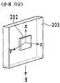
도 36은, 종래의 피에조 저항형 3축 가속도 센서의 개략 구성을 도시하는 사시도로서, 도면 내 부호 201은 실리콘 기판, 201a는 지지부, 201b는 방추부, 201c는 변위부를 나타내고 있다. 실리콘 기판(201)에는, 변위부(201c)와, 이 변위부(201c)를 지지하기 위한 지지부(201a)와, 변위부(201c)를 변형시키기 위한 방추부(201b)가 에칭에 의해 형성되어 있다.Fig. 36 is a perspective view showing a schematic configuration of a conventional piezoresistive triaxial acceleration sensor, in which
또한, 피에조 저항 R1~R12는, 변위부(201c) 상에 형성되어 있다. 실리콘 기판(201)에 가속도가 가해지면, 가속도의 방향 및 크기에 따라서 방추부(201b)가 변위부(201c)를 변형시킨다. 이렇게 하면, 피에조 저항 R1~R12에 응력이 가해져, 저항치가 변화된다.Piezo resistors R1-R12 are formed on the
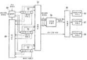
도 37a 내지 도 37c는, 종래의 피에조 저항형 3축 가속도 센서에서의 피에조 저항의 결선 구성을 도시하는 회로도이다. 가속도를 검출하는 축 방향별로, 피에조 저항 R1~R12로 구성되는 휘스턴 브릿지 회로를 각각 구성한다. 출력 전압 Vx, Vy, Vz가 각각 가속도의 x, y, z축 방향 성분에 비례한 값으로 된다.37A to 37C are circuit diagrams showing the wiring configuration of a piezo resistor in a conventional piezoresistive triaxial acceleration sensor. Each whistle bridge circuit composed of piezo resistors R1 to R12 is configured for each axial direction for detecting acceleration. The output voltages Vx, Vy and Vz are respectively proportional to the x, y and z axis components of the acceleration.
도 37a 내지 도 37c에 도시한 회로도에서의 실제 Vx, Vy, Vz는, 다음 수학식과 같이 표현된다.Actual Vx, Vy, and Vz in the circuit diagrams shown in Figs. 37A to 37C are expressed by the following equation.


여기서, Ax, Ay, Az는, 가속도의 x, y, z축 방향 성분, βx, βy, βz는, Ax, Ay, Az에 대한 감도, Vox, Voy, Voz는, Vx, Vy, Vz에 존재하는 오프셋을 나타내고 있다.Here, Ax, Ay, Az are the x, y, z-axis components of the acceleration, βx , βy , βz are the sensitivity to Ax, Ay, Az, Vox , Voy , Voz is Vx The offsets present in, Vy, and Vz are shown.
일반적으로 감도 및 오프셋에는 변동이 있으며, 특히 오프셋의 변동은 무시할 수 없는 경우가 많다. 또한 피에조 저항형의 가속도 센서의 경우, 감도 및 오 프셋은 현저한 온도 특성을 갖는다. 덧붙여 오프셋의 온도 특성은 변동이 큰 경우가 많다.In general, there are variations in sensitivity and offset, and in particular, variations in offset can often be ignored. In the case of piezoresistive acceleration sensors, sensitivity and offset have significant temperature characteristics. In addition, the temperature characteristic of the offset is often large.
이러한 문제를 해결하기 위해서, 종래의 가속도 계측 장치에서는, 다음과 같은 해결 수단을 채용하고 있다(예를 들면, 특허 문헌2 참조).In order to solve such a problem, the following acceleration means is employ | adopted in the conventional acceleration measurement apparatus (for example, refer patent document 2).
즉, 공장 출하 시에서, 예를 들면, 0℃?25℃?60℃라고 하는 서로 다른 복수의 온도 분위기 속에서 감도?오프셋을 계측하고, 가속도 계측 장치에 EEPROM 등의 기억 수단을 탑재하여 이들의 측정 데이터를 기억한다.That is, at the time of factory shipment, the sensitivity and offset are measured in a plurality of different temperature atmospheres, for example, 0 ° C. to 25 ° C. to 60 ° C., and storage means such as an EEPROM is mounted on the acceleration measuring device. Remember the measurement data.
또한, 가속도 계측 장치 사용 시에서, 가속도 계측 장치에 출력 보정 회로를 탑재하고, 현재의 온도 데이터와 앞서 기억된 측정 데이터에 기초하여, 가속도 센서 출력 전압에 포함되는 감도 및 오프셋의 변동과 온도 특성을 연산하여 보정한다.In addition, when the acceleration measuring device is used, the acceleration measuring device is equipped with an output correction circuit, and based on the current temperature data and previously stored measurement data, the sensitivity and offset variations and temperature characteristics included in the acceleration sensor output voltage can be measured. Calculate and correct.
그러나, 종래의 이러한 가속도 계측 장치는, 이하와 같은 결점을 가지고 있다.However, such a conventional acceleration measuring apparatus has the following drawbacks.
1) 서로 다른 복수의 온도 분위기에서의 측정, 및 감도의 측정은 공정 수?측정 시간?설비 코스트를 매우 업시킨다.1) Measurement in a plurality of different temperature atmospheres and the measurement of sensitivity greatly increase the process number, measurement time, and equipment cost.
2) 출력 보정 회로에서의 감도와 오프셋의 온도 특성의 연산은 회로 구성을 복잡하게 만들어 코스트 업으로 된다.2) The calculation of the sensitivity and offset temperature characteristics in the output correction circuit complicates the circuit configuration and leads to cost up.
3) 감도와 오프셋의 온도 특성의 계산 정밀도를 높이기 위해서는 측정 온도를 늘리고, 또한 출력 보정 회로에서의 온도 특성 연산 부분을 더욱 복잡하게 할 필요가 있어, 현실적으로는 곤란하다.3) In order to increase the accuracy of calculating the sensitivity and offset temperature characteristics, it is necessary to increase the measurement temperature and further complicate the temperature characteristic calculation part in the output correction circuit, which is difficult in reality.
또한, 종래의 가속도 계측 장치에서는, 다음과 같은 해결 수단을 더 채용하고 있다(예를 들면, 특허 문헌3 참조).In addition, the conventional acceleration measuring apparatus employ | adopts the following solution means (refer patent document 3).
가속도 계측 장치를 사용할 때마다, 예를 들면, 도 38a 내지 도 38f에 도시한 바와 같이, 3축 가속도 센서(202)의 가속도 검출 축 방향이 중력 가속도 g의 방향과 평행하게 되도록, 가속도 계측 장치(203)의 자세를 6가지로 맞추어 각각 3축 가속도 센서(202)의 출력 전압을 측정하여, 다음의 출력 전압 데이터를 얻는다.Whenever the acceleration measuring device is used, for example, as shown in Figs. 38A to 38F, the acceleration measuring device (the acceleration detecting axis direction of the 3-
Vx1: 도 38a의 자세에서의 Vx 측정치Vx1 : Vx measurement in the posture of FIG. 38A
Vx2: 도 38b의 자세에서의 Vx 측정치Vx2 : Vx measurement in the attitude of FIG. 38B
Vy1: 도 38c의 자세에서의 Vy 측정치Vy1 : Vy measurement in the posture of FIG. 38C
Vy2: 도 38d의 자세에서의 Vy 측정치Vy2 : Vy measurement in the attitude of FIG. 38D
Vz1: 도 38e의 자세에서의 Vz 측정치Vz1 : Vz measurement in the attitude of FIG. 38E
Vz2: 도 38f의 자세에서의 Vz 측정치Vz2 : Vz measurement in the posture of FIG. 38F
3축 가속도 센서의 출력 보정에 필요한 감도와 오프셋의 데이터는, 다음 수학식에 의해 산출된다.The sensitivity and offset data required for output correction of the three-axis acceleration sensor are calculated by the following equation.


그러나, 종래의 이러한 가속도 계측 장치는, 이하와 같은 결점을 가지고 있다.However, such a conventional acceleration measuring apparatus has the following drawbacks.
1) 사용할 때마다, 가속도 계측 장치의 자세를 복수의 특정 방향에 각각 맞출 필요가 있는 것은 사용자에게 있어서 매우 번거롭고 불편하다.1) It is very cumbersome and inconvenient for the user to have to adjust the attitude of the acceleration measuring device to a plurality of specific directions each time it is used.
2) 또한, 사용자가 손으로 가속도 계측 장치를 지지하면서 방향을 정확하게 맞추는 것은 곤란하여, 상기 수학식에 의해 산출되는 감도 및 오프셋은 오차가 커지기 쉽다.2) In addition, it is difficult for the user to accurately adjust the direction while supporting the acceleration measuring device by hand, and the sensitivity and offset calculated by the above equation tend to be large in error.
본 발명은, 이러한 문제를 감안하여 이루어진 것으로, 그 목적으로 하는 바는, 가속도 계측 장치의 자세를 특정 방향을 향하도록 의식하지 않고 2축 또는 3축 가속도 센서의 출력 데이터를 반복 취득함으로써, 2축 또는 3축 가속도 센서의 출력 보정에 필요한 오프셋 혹은 감도와 오프셋의 양방을 취득할 수 있도록 한 가속도 계측 장치를 제공하는 것에 있다.SUMMARY OF THE INVENTION The present invention has been made in view of such a problem, and an object of the present invention is to obtain a biaxial axis by repeatedly acquiring output data of a biaxial or triaxial acceleration sensor without consciously pointing the attitude of the acceleration measurement device toward a specific direction. Another object is to provide an acceleration measuring device capable of acquiring both an offset or a sensitivity required for output correction of a three-axis acceleration sensor and an offset.
[특허 문헌1]: 일본 특허 공개 2003-101033호 공보[Patent Document 1] Japanese Unexamined Patent Publication No. 2003-101033
[특허 문헌2]: 일본 특허 공개 평성 6-331647호 공보[Patent Document 2] Japanese Unexamined Patent Application Publication No. 6-331647
[특허 문헌3]: 일본 특허 공개 2004-93552호 공보[Patent Document 3] Japanese Unexamined Patent Application Publication No. 2004-93552
[비특허 문헌1]: W.H.Press, S.A.Teukolsky, W.T.Vetterling and B.P.Flannery, 年 umerical Recipies in C, Second Edition?Cambridge University Press, USA, 1992, pp.394-455[Non-Patent Document 1]: W.H.Press, S.A.Teukolsky, W.T.Vetterling and B.P.Flannery, Year umerical Recipies in C, Second Edition-Cambridge University Press, USA, 1992, pp. 394-455
[비특허 문헌2]: W.H.Press, S.A.Teukolsky, W.T.Vetterling and B.P.Flannery, 年 umerical Recipies in C, Second Edition?Cambridge University Press, USA, 1992, pp.32-104[Non-Patent Document 2]: W.H.Press, S.A.Teukolsky, W.T.Vetterling and B.P.Flannery, Umerical Recipies in C, Second Edition-Cambridge University Press, USA, 1992, pp. 32-104
〈발명의 개시〉<Start of invention>
본 발명은, 이러한 목적을 달성하기 위해서 이루어진 것으로, 2축 또는 3축 방향의 가속도를 검출하는 가속도 센서와, 그 가속도 센서의 2축 또는 3축의 출력 데이터를 취득하는 출력 데이터 취득 수단과, 상기 출력 데이터 취득 수단이 취득한 출력 데이터를 기준으로 하여, 상기 출력 데이터 취득 수단이 출력 데이터를 취득할 때마다 기준으로 되는 출력 데이터와의 차분을 계산하고, 해당 차분치와 그 차분의 연속 상태를 조사함으로써, 상기 가속도 센서가 정지 상태 또는 등속 운동 상태로 되어 있는지의 여부를 판단하여 출력 데이터를 선택하는 출력 데이터 선택 수단과, 상기 출력 데이터 선택 수단에 의해 선택된 출력 데이터를 축적하는 출력 데이터 축적 수단과, 그 출력 데이터 축적 수단에 의해 축적된 소정 수의 출력 데이터의, 각 축 성분을 좌표치로 했을 때의 2차원 또는 3차원 직교 좌표 공간에서의 분포로부터, 그 직교 좌표 공간 상에 정하는 기준점의 좌표치를 추정하는 기준점 추정 수단과, 그 기준점 추정 수단에 의해 추정된 상기 기준점의 좌표치에 기초하여, 상기 가속도 센서의 출력 데이터의 오프셋을 보정하는 오프셋 보정 수단을 구비하는 것을 특징으로 한다(도 1, 실시예 1에 대응).The present invention has been made to attain such an object, and includes an acceleration sensor for detecting acceleration in a biaxial or triaxial direction, output data acquisition means for acquiring output data for two or three axes of the acceleration sensor, and the output. On the basis of the output data acquired by the data acquiring means, each time the output data acquiring means acquires output data, the difference between the output data as a reference is calculated, and the difference value and the continuous state of the difference are examined. Output data selecting means for selecting output data by determining whether the acceleration sensor is in a stationary state or a constant velocity motion state, output data accumulating means for accumulating output data selected by the output data selecting means, and its output Each axis component of the predetermined number of output data accumulated by the data accumulating means A reference point estimating means for estimating a coordinate value of a reference point determined on the rectangular coordinate space from a distribution in a two-dimensional or three-dimensional rectangular coordinate space when a value is set, and based on the coordinate value of the reference point estimated by the reference point estimating means. And offset correction means for correcting the offset of the output data of the acceleration sensor (corresponding to Fig. 1 and Embodiment 1).
또한, 상기 출력 데이터 선택 수단은, 직전에 취득된 출력 데이터를 기준으로 하는 출력 데이터로서, 상기 출력 데이터 취득 수단에 의해 출력 데이터를 취득할 때마다 기준으로 되는 출력 데이터와의 차분을 계산하고, 그 차분이 소정 횟수 이상 연속하여 소정치 이내인 경우에, 상기 출력 데이터를 적당하다고 판단하여 선택하는 것을 특징으로 한다.The output data selecting means is output data based on the output data acquired immediately before, and each time the output data is obtained by the output data obtaining means, the difference is calculated from the reference output data. When the difference is within a predetermined value for a predetermined number or more consecutive times, the output data is judged to be appropriate and selected.
또한, 상기 출력 데이터 선택 수단은, 상기 출력 데이터 취득 수단이 취득한 소정의 출력 데이터를 기준으로 하여, 상기 출력 데이터 취득 수단에 의해 출력 데이터를 취득할 때마다 기준으로 되는 출력 데이터와의 차분을 계산하고, 기준으로 되는 출력 데이터와 새롭게 취득된 출력 데이터와의 차분이 소정치를 초과할 때까지의 시간이 소정의 임계치 이상인 경우에, 상기 출력 데이터를 적당하다고 판단하여 선택하는 것을 특징으로 한다.Further, the output data selecting means calculates the difference with the reference output data every time the output data is acquired by the output data obtaining means on the basis of the predetermined output data acquired by the output data obtaining means. And when the time until the difference between the output data as a reference and the newly acquired output data exceeds a predetermined value is greater than or equal to a predetermined threshold, the output data is determined to be appropriately selected.
또한, 상기 출력 데이터 선택 수단은, 상기 차분이 연속하여 소정치 이내였던 횟수 또는 시간 정보를, 상기 출력 데이터 선택 수단에 의해 선택된 출력 데이터에 부가하는 것을 특징으로 한다(도 29 내지 도 32, 실시예 6에 대응).The output data selection means adds the number of times or time information that the difference has been continuously within a predetermined value to the output data selected by the output data selection means (Figs. 29 to 32, Example) Corresponding to 6).
삭제delete
또한, 상기 출력 데이터 축적 수단은, 상기 출력 데이터 선택 수단에 의해 부가된 횟수 또는 시간 정보에 기초하여, 상기 출력 데이터 선택 수단에 의해 선택된 출력 데이터와, 상기 출력 데이터 축적 수단에 의해 이미 축적된 출력 데이터 중 어느 하나를 폐기하는 것을 특징으로 한다.The output data accumulating means further includes output data selected by the output data selecting means and output data already accumulated by the output data accumulating means based on the number of times or time information added by the output data selecting means. Discard any one of the.
또한, 상기 출력 데이터 선택 수단은, 상기 출력 데이터 취득 수단에 의해 취득된 소정 수의 출력 데이터의, 각 축 성분을 좌표치로 했을 때의 2차원 또는 3차원 직교 좌표 공간에서의 분포에 기초하여 원 또는 구면을 추정하고, 그 원 또는 구면으로부터 소정 거리 이내에 있는 출력 데이터를 적당하다고 판단하여 선택하는 것을 특징으로 한다.Further, the output data selecting means may be a circle or a circle based on a distribution in a two-dimensional or three-dimensional rectangular coordinate space when each axis component is a coordinate value of a predetermined number of output data acquired by the output data obtaining means. The spherical surface is estimated, and output data within a predetermined distance from the circle or the spherical surface is judged to be appropriate and selected.
또한, 상기 출력 데이터 선택 수단은, 상기 원 또는 구면의 반경을 소정치로 하여 그 원 또는 구면을 추정하는 것을 특징으로 한다.The output data selecting means is characterized by estimating the circle or sphere by setting the radius of the circle or sphere to a predetermined value.
또한, 상기 출력 데이터 선택 수단에 의해 선택된 출력 데이터가, 상기 출력 데이터 축적 수단에 의해 이미 축적된 출력 데이터와 비교하여 소정치 이상 변화되었는지의 여부를 판정하는 데이터 변화 판정 수단을 구비하고, 상기 출력 데이터 축적 수단은, 상기 데이터 변화 판정 수단의 판정 결과에 기초하여, 상기 출력 데이터 선택 수단에 의해 선택된 출력 데이터나, 상기 출력 데이터 축적 수단에 의해 이미 축적된 출력 데이터 중 어느 한 쪽을 폐기하는 것을 특징으로 한다.And the data change determining means for determining whether or not the output data selected by the output data selecting means has changed by more than a predetermined value in comparison with the output data already accumulated by the output data accumulating means. The storage means discards either the output data selected by the output data selecting means or the output data already accumulated by the output data accumulating means, based on the determination result of the data change determining means. do.
또한, 상기 출력 데이터 축적 수단은, 상기 가속도 센서의 측정축과 선형 관계로 되는 선형축을 미리 정하고, 상기 출력 데이터 선택 수단이 선택한 출력 데이터와, 상기 출력 데이터 축적 수단에 축적되어 있는 출력 데이터 중에서, 상기 가 속도 센서의 측정축 또는 선형축의 성분이, 최대 또는 최소로 되는 출력 데이터를 선택적으로 축적하는 것을 특징으로 한다(도 33, 도 34, 실시예 7에 대응).The output data accumulating means predetermines a linear axis in a linear relationship with the measurement axis of the acceleration sensor, and among the output data selected by the output data selecting means and output data accumulated in the output data accumulating means, A component of the measurement axis or the linear axis of the acceleration sensor selectively accumulates output data which is maximum or minimum (corresponding to Figs. 33, 34, and Example 7).
또한, 상기 출력 데이터 축적 수단에 축적되는 출력 데이터는, 상기 측정축 또는 상기 선형축의 성분이 최대 또는 최소로 되는 출력 데이터와, 그 밖의 하나 이상의 출력 데이터를 축적하는 것을 특징으로 한다.The output data accumulated in the output data accumulating means is characterized by accumulating output data in which the component of the measuring axis or the linear axis is maximum or minimum, and at least one other output data.
또한, 상기 기준점 추정 수단은, 상기 출력 데이터 축적 수단에 축적되어 있는 3축의 출력 데이터의 개수 또는 3차원 직교 좌표 공간에서의 분포 및 그 양방으로부터, 상기 기준점 추정 수단에서 구면 또는 타원면을 추정할지를 미리 판단하여, 어느 한 쪽을 선택하여 추정하는 것을 특징으로 한다(도 35, 실시예 8에 대응).Further, the reference point estimating means determines in advance whether the reference point estimating means estimates a spherical or ellipsoid from the number of three-axis output data accumulated in the output data storing means or a distribution in a three-dimensional rectangular coordinate space and both. Then, either one of them is selected and estimated (corresponding to Fig. 35, Example 8).
삭제delete
삭제delete
삭제delete
삭제delete
삭제delete
또한, 상기 가속도 센서의 온도를 검출하는 온도 검출 수단과, 상기 기준점의 좌표치 혹은 상기 타원 또는 타원면의 각 주축의 길이 및 중심 좌표치를 소정의 온도 구분마다 기억하는 온도별 보정 데이터 기억 수단을 구비하고, 상기 출력 데이터 축적 수단은, 상기 출력 데이터 선택 수단에 의해 선택된 출력 데이터를, 상기 온도 검출 수단에 의해 검출된 온도치에 기초하여 상기 소정의 온도 구분별로 축적하고, 상기 기준점 추정 수단은, 상기 소정의 온도 구분마다, 상기 출력 데이터 축적 수단에 의해 축적된 해당 온도 구분의 소정 수의 출력 데이터로부터 상기 기준점의 좌표치 혹은 상기 타원 또는 타원면의 각 주축의 길이 및 중심 좌표치를 추정하고, 상기 온도별 보정 데이터 기억 수단은, 상기 기준점의 좌표치 혹은 상기 타원 또는 타원면의 각 주축의 길이 및 중심 좌표치를 상기 소정의 온도 구분별로 기억하는 것을 특징으로 한다.And a temperature detecting means for detecting the temperature of the acceleration sensor, and temperature-specific correction data storage means for storing the coordinate value of the reference point or the length and center coordinate values of each major axis of the ellipse or ellipsoid at predetermined temperature divisions. The output data accumulating means accumulates the output data selected by the output data selecting means for each of the predetermined temperature divisions based on the temperature value detected by the temperature detecting means, and the reference point estimating means is configured to determine the predetermined data. For each temperature division, the coordinate values of the reference point or the length and center coordinate values of each major axis of the ellipse or ellipsoid are estimated from a predetermined number of output data of the corresponding temperature division accumulated by the output data storing means, and the correction data storage for each temperature is performed. The means may be a coordinate value of the reference point or an angle of the ellipse or ellipsoid. Characterized in that the length of the axis and a central coordinate value stored for each division of the predetermined temperature.
또한, 상기 출력 데이터 축적 수단은, 상기 출력 데이터 선택 수단에 의해 선택된 출력 데이터를, 상기 온도 검출 수단에 의해 검출된 온도치와 해당하는 상기 소정의 온도 구분과의 관계에 기초하여 보정한 후에, 상기 소정의 온도 구분별로 축적하는 것을 특징으로 한다.Further, the output data accumulating means corrects the output data selected by the output data selecting means based on the relationship between the temperature value detected by the temperature detecting means and the corresponding temperature division, and then the It is characterized by accumulating for each predetermined temperature category.
또한, 상기 가속도 센서의 온도를 검출하는 온도 검출 수단과, 상기 기준점의 좌표치 혹은 상기 타원 또는 타원면의 각 주축의 길이 및 중심 좌표치를 소정의 온도 구분마다 기억하는 온도별 보정 데이터 기억 수단을 구비하고, 상기 출력 데이터 축적 수단은, 상기 출력 데이터 선택 수단에 의해 선택된 출력 데이터를 축적할 때에 상기 온도 검출 수단에 의해 검출된 온도치를 함께 축적하고, 상기 기준점 추정 수단은, 상기 소정의 온도 구분마다, 상기 출력 데이터 축적 수단에 의해 축적된 출력 데이터로부터 대응하는 상기 온도치가 해당 온도 구분에 있는 것을 소정 수 선택하여 상기 기준점의 좌표치 혹은 상기 타원 또는 타원면의 각 주축의 길이 및 중심 좌표치를 추정하고, 상기 온도별 보정 데이터 기억 수단은, 상기 기준점의 좌표치 혹은 상기 타원 또는 타원면의 각 주축의 길이 및 중심 좌표치를 상기 소정의 온도 구분별로 기억하는 것을 특징으로 한다.And a temperature detecting means for detecting the temperature of the acceleration sensor, and temperature-specific correction data storage means for storing the coordinate value of the reference point or the length and center coordinate values of each major axis of the ellipse or ellipsoid at predetermined temperature divisions. The output data accumulating means accumulates together the temperature value detected by the temperature detecting means when accumulating the output data selected by the output data selecting means, and the reference point estimating means is configured to output the output at every predetermined temperature division. From the output data accumulated by the data accumulating means, a predetermined number of the corresponding temperature values are selected in the corresponding temperature division, and the coordinate values of the reference point or the length and center coordinate values of each major axis of the ellipse or ellipsoid are estimated, and the temperature-specific correction is performed. The data storage means is a coordinate value or the other value of the reference point. It is characterized by storing the length and the center coordinate value of each main axis of a circle or ellipsoid by said predetermined temperature division.
또한, 상기 오프셋 보정 수단은, 상기 온도 검출 수단에 의해 검출된 온도치, 및 상기 온도별 보정 데이터 기억 수단에 의해 상기 소정의 온도 구분별로 기억된 상기 기준점의 좌표치 혹은 상기 타원 또는 타원면의 각 주축의 길이 및 중심 좌표치에 기초하여, 상기 가속도 센서의 출력 데이터의 오프셋 혹은 감도 및 오프셋을 보정하는 것을 특징으로 한다.Further, the offset correction means includes a coordinate value of the reference point stored for each of the predetermined temperature divisions by the temperature value detected by the temperature detection means, and the temperature-specific correction data storage means, or the coordinates of the respective main axes of the ellipse or ellipsoid. Based on the length and the center coordinate value, the offset or sensitivity and the offset of the output data of the acceleration sensor is characterized in that it is corrected.
또한, 상기 기준점 추정 수단은, 상기 출력 데이터 축적 수단에 의해 축적된 소정 수의 3축의 출력 데이터의 상기 3차원 직교 좌표 공간에서의 분포에 대하여 각 좌표축에 대한 변동을 계산하고, 상기 각 좌표축에 대한 변동의 최소치가 소정치 이하일 때는, 상기 출력 데이터 축적 수단에 의해 축적된 소정 수의 3축의 출력 데이터로부터 상기 변동이 최소치로 되는 좌표축의 출력 데이터를 제외한 나머지 2축의 출력 데이터에 대하여, 각 축 성분을 좌표치로 했을 때의 2차원 직교 좌표 평면에서의 분포로부터, 상기 2차원 직교 좌표 평면 상에 정하는 기준점의 좌표치 혹은 타원의 각 주축의 길이 및 중심 좌표치를 추정하고, 상기 오프셋 보정 수단은, 상기 기준점의 좌표치 혹은 상기 타원의 각 주축의 길이 및 중심 좌표치에 기초하여, 상기 가속도 센서의 2축의 출력 데이터의 오프셋 혹은 감도와 오프셋을 보정하는 것을 특징으로 한다.Further, the reference point estimating means calculates a variation for each coordinate axis with respect to a distribution in the three-dimensional rectangular coordinate space of a predetermined number of three-axis output data accumulated by the output data accumulating means, and calculates a variation for each coordinate axis. When the minimum value of the variation is less than or equal to the predetermined value, each axis component is output from the output data of the predetermined number of three axes accumulated by the output data accumulating means, except for the output data of the remaining two axes except for the output data of the coordinate axis whose minimum value is changed. From the distribution in the two-dimensional rectangular coordinate plane at the time of the coordinate value, the coordinate value of the reference point determined on the two-dimensional rectangular coordinate plane or the length and the center coordinate value of each major axis of the ellipse are estimated, and the offset correction means Based on the coordinate value or the length and center coordinate value of each major axis of the ellipse, It is characterized by correcting the offset or sensitivity and offset of the output data of two axes.
삭제delete
삭제delete
또한, 상기 기준점 추정 수단은, 그 기준점 추정 수단에 의해 추정된 바로 근접한 소정 수의 기준점의 좌표치 혹은 타원 또는 타원면의 중심 좌표치의 변동을 산출하여, 상기 변동이 소정치보다도 큰 경우에는, 상기 기준점의 좌표치 혹은 상기 타원 또는 타원면의 중심 좌표치를 파기하는 것을 특징으로 한다.Further, the reference point estimating means calculates a change in the coordinate values of the immediately adjacent predetermined number of reference points estimated by the reference point estimating means or the center coordinate value of the ellipse or ellipsoid, and when the variation is larger than the predetermined value, And discarding a coordinate value or a center coordinate value of the ellipse or ellipsoid.
또한, 상기 기준점 추정 수단은, 상기 2차원 또는 3차원 직교 좌표 공간에서 추정된 상기 기준점부터 상기 소정 수의 출력 데이터 각각까지의 거리 혹은 추정된 타원 또는 타원면의 각 주축의 길이가 소정 범위 외인 경우, 상기 기준점의 좌표치 혹은 상기 타원 또는 타원면의 각 주축의 길이 및 중심 좌표치를 파기하는 것을 특징으로 한다.Further, the reference point estimating means, when the distance from the reference point estimated in the two-dimensional or three-dimensional rectangular coordinate space to each of the predetermined number of output data or the length of each major axis of the estimated ellipse or ellipsoid is outside a predetermined range, And dividing the coordinate value of the reference point or the length and center coordinate values of each major axis of the ellipse or ellipsoid.
본 발명에 따르면, 가속도 계측 장치의 사용 시에서, 가속도 계측 장치의 자세를 특정 방향을 향하도록 의식하지 않고 2축 또는 3축 가속도 센서의 출력 데이터를 반복 취득함으로써, 2축 또는 3축 가속도 센서의 출력 보정에 필요한 오프셋 혹은 감도와 오프셋의 양방을 취득할 수 있다.According to the present invention, in the use of the acceleration measuring device, by repeatedly acquiring the output data of the two-axis or three-axis acceleration sensor without conscious of the attitude of the acceleration measuring device toward a specific direction, The offset required for output correction or both the sensitivity and the offset can be obtained.
또한, 가속도 계측 장치의 사용 시에서, 기지의 한 자세에 놓여 있는 상태, 예를 들면 충전기에 세트하고 있는 상태에서 2축 또는 3축 가속도 센서의 출력 데이터를 취득함으로써, 2축 또는 3축 가속도 센서의 출력 보정에 필요한 오프셋을 취득할 수 있다.In addition, when using an acceleration measuring device, the biaxial or triaxial acceleration sensor is acquired by acquiring the output data of the biaxial or triaxial acceleration sensor in a state in a known posture, for example, in a state of being set in a charger. The offset required for output correction can be obtained.
또한, 공장 출하 시에서 서로 다른 복수의 온도 분위기 속에서 감도?오프셋을 계측하여 기억할 필요가 없어진다. 출력 보정 회로에서 감도 및 오프셋의 온도 특성을 연산할 필요가 없어진다. 사용할 때마다, 가속도 계측 장치의 자세를 복수의 특정 방향에 각각 맞출 필요도 없어진다.In addition, there is no need to measure and store the sensitivity and offset in a plurality of different temperature atmospheres at the time of factory shipment. In the output correction circuit, there is no need to calculate the temperature characteristics of the sensitivity and the offset. Each use eliminates the need to adjust the attitude of the acceleration measurement device to a plurality of specific directions, respectively.
또한, 본 발명은, 3축 지자기 검출 수단을 갖는 방위각 센서와 조합하여 5축 또는 6축 센서로 할 수 있으며, 이 경우에도 마찬가지의 효과를 얻을 수 있다.Moreover, this invention can be set as a 5-axis or 6-axis sensor in combination with the azimuth sensor which has a 3-axis geomagnetic detection means, and a similar effect can also be acquired in this case.
도 1은, 본 발명의 가속도 계측 장치의 실시예 1을 설명하기 위한 구성도.BRIEF DESCRIPTION OF THE DRAWINGS The block diagram for demonstrating Example 1 of the acceleration measuring apparatus of this invention.
도 2는, 본 발명의 실시예 1에서의 기준점의 개념도.2 is a conceptual diagram of a reference point in
도 3은, 본 발명의 실시예 1에서의 기준점 추정의 개념도.3 is a conceptual diagram of reference point estimation in
도 4는, 본 발명의 실시예 1에서의 3축 출력 데이터 선택의 구체적 방법(그 1)의 개념도.Fig. 4 is a conceptual diagram of a concrete method (No. 1) of triaxial output data selection in
도 5는, 본 발명의 실시예 1에서의 3축 출력 데이터 선택의 구체적 방법(그 1)을 도시하는 구성도.Fig. 5 is a block diagram showing a specific method (1) of triaxial output data selection in the first embodiment of the present invention.
도 6은, 본 발명의 실시예 1에서의 3축 출력 데이터 선택의 구체적 방법(그 2)의 개념도.Fig. 6 is a conceptual diagram of a concrete method (No. 2) of triaxial output data selection in
도 7은, 본 발명의 실시예 1에서의 데이터 변화 판정부의 구체적인 구성도.Fig. 7 is a specific configuration diagram of the data change determining unit in the first embodiment of the present invention.
도 8은, 본 발명의 실시예 1에서의 기준점 좌표 데이터를 취득하는 수순을 설명하기 위한 플로우차트를 도시하는 도면(그 1).FIG. 8 is a diagram (1) showing a flowchart for explaining the procedure for acquiring reference point coordinate data according to the first embodiment of the present invention. FIG.
도 9는, 본 발명의 실시예 1에서의 기준점 좌표 데이터를 취득하는 수순을 설명하기 위한 플로우차트를 도시하는 도면(그 2).Fig. 9 is a diagram showing a flowchart for explaining a procedure of acquiring reference point coordinate data in the first embodiment of the present invention (No. 2).
도 10은, 본 발명의 실시예 1에서의 기준점 좌표 데이터를 취득하는 수순을 설명하기 위한 플로우차트를 도시하는 도면(그 3).FIG. 10 is a diagram illustrating a flowchart for explaining a procedure of acquiring reference point coordinate data according to the first embodiment of the present invention (part 3). FIG.
도 11은, 본 발명의 가속도 계측 장치의 실시예 2를 설명하기 위한 구성도.11 is a configuration diagram for describing a second embodiment of the acceleration measurement device of the present invention.
도 12는, 본 발명의 실시예 2에서의 타원면 주축 길이?중심 좌표의 개념도.Fig. 12 is a conceptual diagram of ellipsoidal major axis length? Center coordinates in the second embodiment of the present invention.
도 13은, 본 발명의 실시예 2에서의 타원면 주축 길이?중심 좌표 추정의 개념도.Fig. 13 is a conceptual diagram of ellipsoidal major axis length? Center coordinate estimation in the second embodiment of the present invention.
도 14는, 본 발명의 실시예 2에서의 타원면 주축 길이?중심 좌표 데이터를 취득하는 수순을 설명하기 위한 플로우차트를 도시하는 도면(그 1).FIG. 14 is a flowchart for explaining a procedure for acquiring the ellipsoidal main axis length? Center coordinate data according to the second embodiment of the present invention (No. 1). FIG.
도 15는, 본 발명의 실시예 2에서의 타원면 주축 길이?중심 좌표 데이터를 취득하는 수순을 설명하기 위한 플로우차트를 도시하는 도면(그 2).FIG. 15 is a flowchart for explaining a procedure of acquiring ellipsoidal spindle axis length-center coordinate data according to the second embodiment of the present invention (No. 2). FIG.
도 16은, 본 발명의 실시예 2에서의 타원면 주축 길이?중심 좌표 데이터를 취득하는 수순을 설명하기 위한 플로우차트를 도시하는 도면(그 3).FIG. 16 is a flowchart for explaining a procedure of acquiring ellipsoidal main axis length? Center coordinate data according to the second embodiment of the present invention (No. 3). FIG.
도 17은, 본 발명의 가속도 계측 장치의 실시예 3을 설명하기 위한 구성도.17 is a configuration diagram for describing a third embodiment of an acceleration measurement device of the present invention.
도 18a는, 본 발명의 실시예 3을 설명하기 위한 개념도(그 1).18A is a conceptual diagram (No. 1) for explaining a third embodiment of the present invention.
도 18b는, 본 발명의 실시예 3을 설명하기 위한 개념도(그 2).18B is a conceptual diagram (2) for illustrating the third embodiment of the present invention.
도 19는, 본 발명의 실시예 3에서의 기준점 추정의 개념도.Fig. 19 is a conceptual diagram of reference point estimation in the third embodiment of the present invention.
도 20은, 본 발명의 가속도 계측 장치의 실시예 4를 설명하기 위한 구성도.20 is a configuration diagram for describing a fourth embodiment of the acceleration measurement device of the present invention.
도 21은, 본 발명의 실시예 4에서의 기준점 좌표 데이터를 취득하는 수순을 설명하기 위한 플로우차트를 도시하는 도면(그 1).Fig. 21 is a diagram showing a flowchart for explaining the procedure of acquiring reference point coordinate data in the fourth embodiment of the present invention (No. 1).
도 22는, 본 발명의 실시예 4에서의 기준점 좌표 데이터를 취득하는 수순을 설명하기 위한 플로우차트를 도시하는 도면(그 2).Fig. 22 is a diagram showing a flowchart for explaining a procedure of acquiring reference point coordinate data in the fourth embodiment of the present invention (No. 2).
도 23은, 본 발명의 가속도 계측 장치의 실시예 5를 설명하기 위한 구성도.Fig. 23 is a configuration diagram for describing a fifth embodiment of the acceleration measurement device of the present invention.
도 24는, 본 발명의 실시예 5에서의 기준점 좌표 데이터를 취득하는 수순을 설명하기 위한 플로우차트를 도시하는 도면(그 1).FIG. 24 is a diagram (1) showing a flowchart for explaining the procedure for acquiring reference point coordinate data in the fifth embodiment of the present invention. FIG.
도 25는, 본 발명의 실시예 5에서의 기준점 좌표 데이터를 취득하는 수순을 설명하기 위한 플로우차트를 도시하는 도면(그 2).Fig. 25 is a flowchart showing a flowchart for explaining the procedure for acquiring reference point coordinate data in the fifth embodiment of the present invention (No. 2).
도 26은, 온도 특성에의 대응에 관한 제1 해결 수단을 설명하기 위한 구성도.Fig. 26 is a configuration diagram for explaining a first solution means for responding to a temperature characteristic.
도 27은, 온도 특성에의 대응에 관한 제2 해결 수단을 설명하기 위한 구성 도.27 is a configuration diagram for explaining a second solution means for responding to a temperature characteristic;
도 28은, 온도 특성에의 대응에 관한 제3 해결 수단을 설명하기 위한 구성도.FIG. 28 is a configuration diagram for explaining a third solution means for responding to a temperature characteristic; FIG.
도 29는, 본 발명의 실시예 6에서의 3축 출력 데이터의 개념도(그 1).Fig. 29 is a conceptual diagram (No. 1) of three-axis output data in the sixth embodiment of the present invention.
도 30은, 본 발명의 실시예 6에서의 데이터를 선택하는 수순을 설명하기 위한 플로우차트를 도시하는 도면.Fig. 30 is a flowchart for explaining a procedure for selecting data in the sixth embodiment of the present invention.
도 31은, 본 발명의 실시예 6에서의 3축 출력 데이터의 개념도(그 2).Fig. 31 is a conceptual diagram (three) of three-axis output data in the sixth embodiment of the present invention.
도 32는, 본 발명의 실시예 6에서의 데이터 버퍼 내의 측정 데이터를 교체하는 수순을 설명하기 위한 플로우차트를 도시하는 도면.Fig. 32 is a flowchart for explaining a procedure for replacing measurement data in the data buffer in the sixth embodiment of the present invention.
도 33은, 본 발명의 실시예 7에서의 데이터 변화 판정부의 구체적인 구성도.Fig. 33 is a specific configuration diagram of the data change determining unit in the seventh embodiment of the present invention.
도 34는, 본 발명의 실시예 7에서의 데이터 버퍼 내의 측정 데이터를 교체하는 수순을 설명하기 위한 플로우차트를 도시하는 도면.Fig. 34 is a flowchart for explaining a procedure for replacing measurement data in the data buffer in the seventh embodiment of the present invention.
도 35는, 본 발명의 실시예 8에서의 구체 적용과 타원체 적용의 절환의 구체적 방법을 설명하기 위한 플로우차트를 도시하는 도면.Fig. 35 is a flowchart for explaining a specific method of switching between concrete application and ellipsoid application in the eighth embodiment of the present invention.
도 36은, 종래의 피에조 저항형 3축 가속도 센서의 개략 구성을 도시하는 사시도.36 is a perspective view showing a schematic configuration of a conventional piezoresistive three-axis acceleration sensor.
도 37a는, 종래의 피에조 저항형 3축 가속도 센서에서의 피에조 저항의 결선 구성을 도시하는 회로도(그 1).Fig. 37A is a circuit diagram (1) showing a wiring configuration of a piezo resistor in a conventional piezoresistive triaxial acceleration sensor.
도 37b는, 종래의 피에조 저항형 3축 가속도 센서에서의 피에조 저항의 결선 구성을 도시하는 회로도(그 2).Fig. 37B is a circuit diagram (2) showing a wiring configuration of a piezo resistor in a conventional piezoresistive triaxial acceleration sensor.
도 37c는, 종래의 피에조 저항형 3축 가속도 센서에서의 피에조 저항의 결선 구성을 도시하는 회로도(그 3).Fig. 37C is a circuit diagram (3) showing a wiring configuration of a piezo resistor in a conventional piezoresistive three-axis acceleration sensor.
도 38a는, 종래의 가속도 계측 장치에서 출력 보정을 행하기 위한 감도?오프셋 데이터를 얻는 한 방법을 설명하기 위한 도면(그 1).38A is a diagram for explaining one method of obtaining sensitivity and offset data for output correction in a conventional acceleration measurement apparatus (No. 1).
도 38b는, 종래의 가속도 계측 장치에서 출력 보정을 행하기 위한 감도?오프셋 데이터를 얻는 한 방법을 설명하기 위한 도면(그 2).38B is a diagram for explaining one method of obtaining sensitivity and offset data for output correction in a conventional acceleration measurement apparatus (No. 2).
도 38c는, 종래의 가속도 계측 장치에서 출력 보정을 행하기 위한 감도?오프셋 데이터를 얻는 한 방법을 설명하기 위한 도면(그 3).38C is a diagram for explaining one method of obtaining sensitivity and offset data for performing output correction in a conventional acceleration measurement apparatus (No. 3).
도 38d는, 종래의 가속도 계측 장치에서 출력 보정을 행하기 위한 감도?오프셋 데이터를 얻는 한 방법을 설명하기 위한 도면(그 4).38D is a diagram for explaining one method of obtaining sensitivity and offset data for performing output correction in a conventional acceleration measurement apparatus (No. 4).
도 38e는, 종래의 가속도 계측 장치에서 출력 보정을 행하기 위한 감도?오프셋 데이터를 얻는 한 방법을 설명하기 위한 도면(그 5).38E is a diagram for explaining one method of obtaining sensitivity and offset data for performing output correction in a conventional acceleration measurement apparatus (No. 5).
도 38f는, 종래의 가속도 계측 장치에서 출력 보정을 행하기 위한 감도?오프셋 데이터를 얻는 한 방법을 설명하기 위한 도면(그 6).38F is a diagram for explaining one method of obtaining sensitivity and offset data for output correction in a conventional acceleration measurement apparatus (No. 6).
〈발명을 실시하기 위한 최량의 형태〉<The best form to perform invention>
이하, 도면을 참조하여 본 발명의 각 실시예에 대하여 설명한다.EMBODIMENT OF THE INVENTION Hereinafter, each Example of this invention is described with reference to drawings.
또한, 도 1에 도시한 실시예 1은, 본 발명에 따른 가속도 계측 장치의 기본적인 구성을 도시한 것으로, 3축 가속도 센서로부터 취득한 데이터로부터 적정한 데이터를 선택하고, 3차원 직교 좌표 공간 상에 정하는 기준점의 좌표치를 추정함으로써 오프셋의 보정을 행하는 것이다.In addition, Example 1 shown in FIG. 1 shows the basic structure of the acceleration measuring device which concerns on this invention, The reference point which selects appropriate data from the data acquired from the 3-axis acceleration sensor, and determines it on a three-dimensional rectangular coordinate space. The offset is corrected by estimating the coordinate value of.
이에 대하여, 도 11에 도시한 실시예 2는, 기준점의 추정으로서, 3차원 직교 좌표 공간 상에 타원면을 정하여 주축의 길이 및 중심 좌표치의 추정을 행함으로써 감도와 오프셋의 보정을 행하는 것이다.In contrast, the second embodiment shown in Fig. 11 corrects the sensitivity and the offset by estimating an ellipsoidal surface in a three-dimensional rectangular coordinate space and estimating the length and center coordinate values of the main axis as an estimate of the reference point.
또한, 도 17에 도시한 실시예 3은, 기준점의 추정을, 3축 가속도 센서가 검지하고 있다고 예상되는 중력 가속도의 각 축 성분의 값으로부터, 3차원 직교 좌표 공간 상에 정하는 기준점의 좌표치를 추정하는 것이다.In addition, in Example 3 shown in FIG. 17, the estimation of the reference point estimates the coordinate value of the reference point set on a three-dimensional rectangular coordinate space from the value of each axis component of gravitational acceleration which the 3-axis acceleration sensor is estimated to detect. It is.
또한, 도 20에 도시한 실시예 4는, 기준점의 추정을, 3차원 직교 좌표 공간 상에 정하는 기준점의 좌표치를 소정 수의 3축 출력 데이터의 각각부터 기준점까지의 거리의 변동이 최소로 되도록 통계적 방법에 의해 추정하는 것이다.In addition, in Example 4 shown in FIG. 20, the estimation of the reference point is statistically performed so that the variation of the distance from each of a predetermined number of three-axis output data to the reference point is minimized. It is estimated by the method.
또한, 도 23에 도시한 실시예 5는, 기준점의 추정을, 3차원 직교 좌표 공간 상에 정하는 타원면의 각 주축의 길이 및 중심 좌표치를 소정 수의 3축 출력 데이터 각각이 타원면에 가장 근접하도록 통계적 방법에 의해 추정하는 것이다.In addition, in Example 5 shown in FIG. 23, the length and center coordinate value of each major axis of the ellipsoid which estimates a reference point on a three-dimensional rectangular coordinate space are statistically so that each of a predetermined number of three-axis output data may be closest to an ellipsoid. It is estimated by the method.
또한, 도 29 내지 도 32에 도시한 실시예 6은, 3축 가속도 센서에서, 가속도 센서가 중력 가속도만을 받는 경우, 즉, 정지하고 있는 경우의 가속도 센서의 출력 데이터(측정 데이터)의 분포가, 3차원 직교 좌표계에서 구면 또는 타원면을 형성하기 때문에, 정지 판정을 행하여, 이 구면 또는 타원면의 중심치를 구함으로써 오프셋을 추정하도록 한 것이다.29 to 32, the distribution of the output data (measurement data) of the acceleration sensor when the acceleration sensor receives only gravity acceleration, that is, when it is stopped, in the three-axis acceleration sensor, Since a spherical surface or an ellipsoidal surface is formed in the three-dimensional rectangular coordinate system, the stop determination is performed to estimate the offset by obtaining the center value of the spherical surface or the ellipsoidal surface.
또한, 도 33 및 도 34에 도시한 실시예 7은, 가속도 센서의 측정축 및 이들과 선형 관계에 있는 축을 규정하고, 그 축 상에서 최대 또는 최소로 되는 출력 데이터를 우선적으로 축적함으로써, 타원면 적용 계산에서 추정 오차가 작아지는 데 이터군을 얻는 것이다.Further, the seventh embodiment shown in Figs. 33 and 34 defines the measurement axis of the acceleration sensor and the axis in linear relationship with these, and the ellipsoid application calculation is calculated by preferentially accumulating the maximum or minimum output data on the axis. In order to obtain the data group, the estimation error becomes smaller.
또한, 도 35에 도시한 실시예 8은, 출력 데이터 축적 수단에 축적되어 있는 출력 데이터의 개수 또는 3차원 직교 좌표 공간에서의 분포로부터, 구면 또는 타원면을 추정할지를 미리 판정하여, 어느 한 쪽을 선택하여 추정하는 것이다.Further, the eighth embodiment shown in Fig. 35 determines in advance whether to estimate a spherical surface or an ellipsoid from the number of output data accumulated in the output data storage means or the distribution in the three-dimensional rectangular coordinate space. To estimate.
(실시예 1)(Example 1)
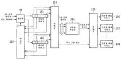
도 1은, 본 발명의 가속도 계측 장치의 실시예 1을 설명하기 위한 구성도로, 3축 가속도 센서로부터 취득한 데이터로부터 적정한 데이터를 선택하고, 3차원 직교 좌표 공간 상에 정하는 기준점의 좌표치를 추정함으로써 오프셋의 보정을 행하는 것이다.Fig. 1 is a configuration diagram for explaining
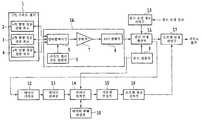
도면 내 부호 1은 3축 가속도 센서, 2는 3축 가속도 센서의 x축 방향 성분 검출 회로, 3은 3축 가속도 센서의 y축 방향 성분 검출 회로, 4는 3축 가속도 센서의 z축 방향 성분 검출 회로, 5A는 데이터 취득부(출력 데이터 취득 수단), 5는 멀티플렉서부, 6은 가속도 센서 구동 전원부, 7은 증폭부, 8은 A/D 변환부, 9는 온도 검출부, 10은 감도 보정 정보 기억부, 11은 감도 보정 계산부, 12는 데이터 기억부, 13은 데이터 선택부(출력 데이터 선택 수단), 14는 데이터 축적부(출력 데이터 축적 수단), 15는 기준점 추정부(기준점 추정 수단), 16은 오프셋 정보 기억부, 17은 오프셋 보정 계산부(오프셋 보정 수단), 18은 데이터 변화 판정부(데이터 변화 판정 수단)를 나타내고 있다.In the drawings,
본 실시예 1의 가속도 계측 장치는, 3축 방향의 가속도를 검출하는 3축 가속도 센서(1)와, 이 3축 가속도 센서(1)의 3축 출력 데이터를 취득하는 데이터 취득부(5A)와, 이 데이터 취득부(5A)에 의해 반복 취득된 3축 출력 데이터가 적당한지의 여부를 판단하여 선택하는 데이터 선택부(13)와, 이 데이터 선택부(13)에 의해 선택된 3축 출력 데이터를 축적하는 데이터 축적부(14)와, 이 데이터 축적부(14)에 의해 축적된 소정 수의 3축 출력 데이터의, 각 축 성분을 좌표치로 했을 때의 3차원 직교 좌표 공간에서의 분포로부터, 3차원 직교 좌표 공간 상에 정하는 기준점의 좌표치를 추정하는 기준점 추정부(15)와, 이 기준점 추정부(15)에 의해 추정된 기준점의 좌표치에 기초하여, 3축 가속도 센서(1)의 3축 출력 데이터의 오프셋을 보정하는 오프셋 보정 계산부(17)를 구비하고 있다. 또한, 데이터 취득부(5A)는, 멀티플렉서부(5)와 가속도 센서 구동 전원부(6)와 증폭부(7)와 A/D 변환부(8)로 구성되어 있다.The acceleration measuring apparatus of the first embodiment includes a three-
3축 가속도 센서(1)는, x축 방향 성분 검출 회로(2)와 y축 방향 성분 검출 회로(3)와 z축 방향 성분 검출 회로(4)를 구비하고 있다. x축 방향 성분 검출 회로(2)와 y축 방향 성분 검출 회로(3)와 z축 방향 성분 검출 회로(4)는, 각각 가속도의 x축 방향과 y축 방향 및 z축 방향 성분을 검출한다. 멀티플렉서부(5)는, 가속도 센서 구동 전원부(6)와 증폭부(7)를 시분할로, x축 방향 성분 검출 회로(2)와 y축 방향 성분 검출 회로(3)와 z축 방향 성분 검출 회로(4)에 접속되어 있다.The three-
가속도 센서 구동 전원부(6)는, 멀티플렉서부(5)를 통하여, 시분할로 x축 방향 성분 검출 회로(2)와 y축 방향 성분 검출 회로(3)와 z축 방향 성분 검출 회로(4)에 전원을 공급한다. 증폭부(7)는, 멀티플렉서부(5)를 통하여, 시분할로 x축 방향 성분 검출 회로(2)와 y축 방향 성분 검출 회로(3)와 z축 방향 성분 검출 회로(4)의 출력 전압을 증폭한다.The acceleration sensor drive
A/D 변환부(8)는, 증폭부(7)에 의해 증폭된 x축 방향 성분 검출 회로(2)와 y축 방향 성분 검출 회로(3)와 z축 방향 성분 검출 회로(4)의 출력 전압을 A/D 변환하여, 3축 출력 데이터로서 출력한다. 온도 검출부(9)는, 3축 가속도 센서(1)의 온도를 검출한다. 감도 보정 정보 기억부(10)는, 소정의 감도 보정 정보를 기억한다. 감도 보정 계산부(11)는, 온도 검출부(9)로부터 취득한 온도 데이터 및 감도 보정 정보 기억부(10)에 기억되어 있는 감도 보정 정보에 기초하여, A/D 변환부(8)로부터 출력된 3축 출력 데이터의 감도 보정을 행한다.The A /
데이터 기억부(12)는, 감도 보정 계산부(11)로부터 축차적으로 출력되는 3축 출력 데이터를 소정 수 유지하는 FIFO형 데이터 버퍼이다. 데이터 선택부(13)는, 데이터 기억부(12)에 유지되고 있는 3축 출력 데이터로부터, 기준점 추정부(15)에서 실시하는 기준점 좌표의 추정에 적합한 데이터를 선택한다.The
데이터 축적부(14)는, 데이터 선택부(13)에서 선택된 3축 출력 데이터를 소정 수 축적하는 데이터 버퍼이다. 기준점 추정부(15)는, 데이터 축적부(14)에 축적된 소정 수의 3축 출력 데이터에 기초하여 기준점의 좌표를 추정하여 기준점 좌표 데이터를 출력한다.The data accumulator 14 is a data buffer that accumulates a predetermined number of three-axis output data selected by the
오프셋 정보 기억부(16)는, 기준점 추정부(15)로부터 출력된 기준점 좌표 데이터를 기억한다. 오프셋 보정 계산부(17)는, 오프셋 정보 기억부(16)에서 기억되어 있는 기준점 좌표 데이터에 기초하여, 감도 보정 계산부(11)로부터 출력된 3축 출력 데이터의 오프셋 보정을 행한다.The offset
다음으로, 기준점 추정부(15)에서의 기준점의 좌표를 추정하는 방법에 대하 여 설명한다.Next, a method of estimating the coordinates of the reference point in the reference
감도 보정 계산부(11)로부터 출력되는, 감도 보정된 3축 출력 데이터 Sx, Sy, Sz는, 다음 수학식과 같이 표현된다.Sensitivity-corrected triaxial output data Sx, Sy, Sz output from the


여기서, a는, 보정된 감도, Cx, Cy, Cz는, Sx, Sy, Sz에 존재하는 오프셋이다. 가속도 계측 장치가 정지하고 있다든지, 등속 운동을 행하고 있는 경우, 3축 가속도 센서(1)가 받고 있는 가속도는 중력 가속도 g뿐이다. 따라서, 중력 가속도 g의 x, y, z축 방향 성분을 Gx, Gy, Gz로 하면, 이하와 같이 된다.Here, a is a corrected sensitivity, Cx, Cy, and Cz are offsets present in Sx, Sy, and Sz. When the acceleration measuring device is stopped or is performing constant velocity motion, the acceleration received by the three-


한편,Meanwhile,

따라서,therefore,

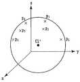
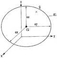
상기 수학식 20에 따르면, 도 2에 도시한 바와 같이, 3차원 직교 좌표 공간(x, y, z)에서 3축 출력 데이터의 각 축 성분을 좌표치로 하는 점 P(Sx, Sy, Sz)는, 3축 출력 데이터의 각 축 성분의 오프셋치를 좌표치로 하는 기준점 C1(Cx, Cy, Cz)로부터 반드시 일정한 거리 ag를 두고 위치하게 된다.According to
이번에는, N개의 서로 다른 3축 가속도 센서(1)의 자세에서 각각 감도 보정 계산부(11)로부터 출력되는 3축 출력 데이터를 취득하여, 각 축 성분의 데이터를 각각This time, the 3-axis output data output from the sensitivity
S1x, S2x, …SNxS1x , S2x ,... SNx
S1y, S2y, …SNyS1y , S2y ,... SNy
S1z, S2z, …SNzS1z , S2z,. SNz
로 표기한다. 다음으로, 3차원 직교 좌표 공간(x, y, z)에서, 취득한 3축 출력 데이터를It is written as. Next, the three-axis output data acquired in the three-dimensional rectangular coordinate space (x, y, z) is
P1(S1x, S1y, S1z), P2(S2x, S2y, S2z), P3(S3x, S3y, S3z)P1 (S1x , S1y , S1z ), P2 (S2x , S2y , S2z ), P3 (S3x , S3y , S3z )
로 이루어지는 N개의 점으로서 나타내는 것으로 한다.It is assumed as N points which consist of.
이렇게 하면 도 3에 도시하는 바와 같이, P1, P2, …, PN의 어느 하나로부터도 거리가 일정해지는 점 C1'(Cx', Cy', Cz')를 추정하면, 점 C1'는 기준점 C1에 상당하는 것이 기대되고, 점 C1'의 좌표치 Cx', Cy', Cz'를 가지고 각 축 성분의 오프셋치 Cx, Cy, Cz를 추정할 수 있다.This allows P1 , P2,... When the point C1 '(Cx', Cy ', Cz') whose distance is constant from any of PN is estimated, the point C1 'is expected to correspond to the reference point C1, and the coordinate value Cx' of the point C1 ', The offset values Cx, Cy, and Cz of each axis component can be estimated with Cy 'and Cz'.
<C1'(Cx', Cy', Cz')를 추정하는 구체적 방법(그 1)><Specific method for estimating C1 '(Cx', Cy ', Cz') (part 1)>
기준점 추정부(15)는, 기준점의 좌표치를, 소정 수의 3축 출력 데이터의 각각부터 기준점까지의 거리의 변동이 최소로 되도록 통계적 방법에 의해 추정한다.The reference
P1, P2, …, PN으로부터 C1'(Cx', Cy', Cz')를 추정하기 위해서는 다양한 방법 이 있으며, 최저 N=4에서 추정 가능하다.P1 , P2,. In order to estimate C1 '(Cx', Cy ', Cz') from PN , there are various methods, which can be estimated at the lowest N = 4.
그러나, 피에조 저항형 3축 가속도 센서의 감도는 몇 백 μV/G/V 정도밖에 안되기 때문에, 출력 전압이 매우 미약하여, 취득된 3축 출력 데이터에는 상당한 노이즈가 중첩된다.However, since the sensitivity of the piezoresistive triaxial accelerometer is only a few hundred μV / G / V, the output voltage is very weak, and considerable noise is superimposed on the obtained triaxial output data.
3차원 직교 좌표 공간(x, y, z)에서, i번째의 3축 출력 데이터의 점 Pi(Six, Siy, Siz)로부터 C1'(Cx', Cy', Cz')까지의 거리 d는 다음과 같이 된다.In the three-dimensional rectangular coordinate space (x, y, z), from the point Pi (Six , Siy , Siz ) of the i-th 3-axis output data to C1 '(Cx', Cy ', Cz') The distance d becomes

상기 수학식 21과 상기 수학식 20을 비교함으로써, 이상적으로는 P1, P2, …, PN의 전체에 대하여 di=ag의 일정치로 될 것이다.By comparing
그러나, 취득된 3축 출력 데이터에는 상당한 노이즈가 중첩하고 있으므로 di=ag로는 되지 않는다.However, since significant noise is superimposed on the obtained three-axis output data, di = ag is not set.
따라서 N을 늘리고, di의 변동이 최소로 되도록 통계적 방법을 이용하여 C1'(Cx', Cy', Cz')를 추정하면, 상당한 노이즈가 중첩하고 있더라도 정밀도 높은 추정이 가능해진다.Therefore, if N is increased and C1 '(Cx', Cy ', Cz') is estimated using a statistical method so that the variation in di is minimized, accurate estimation is possible even if a considerable amount of noise overlaps.
di의 변동을 나타내는 값으로서, 다음 수학식으로 표현된 바와 같은 Z1을 정의한다.As a value representing the variation of di , Z1 as expressed by the following equation is defined.

여기에서, r2는 di2의 평균치이며 다음 수학식으로 표현된다.Here, r2 is the average value of di2 and is represented by the following equation.

이 Z1이 최소로 되도록 Cx', Cy', Cz'를 결정하면 된다.What is necessary is just to determine Cx ', Cy', and Cz 'so that this Z <1> may become minimum.
상기 수학식 23에 대하여 최적화 방법(예를 들면, 비특허 문헌1 참조)을 이용하여 직접 Cx', Cy', Cz'를 계산해도 되지만, 해가 수속할 때까지 반복 계산하게 되므로, 이하의 방법을 이용하면 계산 시간 등의 점에서 유리하다.Although Cx ', Cy', and Cz 'may be calculated directly with respect to
상기 수학식 23을 Cx', Cy', Cz'로 편미분하여, 어느 편미분치나 0으로 된 경우, 즉When the


이 성립했을 때에 Z1이 최소로 된다고 추정한다.When this is established, it is assumed that Z1 is minimized.
상기 수학식 24 내지 26을 전개하면, Cx', Cy', Cz'에 관하여 다음 수학식으로 표현된 바와 같은 연립 1차 방정식이 도출된다. 따라서, 콜레스키 분해 등의 잘 알려진 연립 1차 방정식의 해법(예를 들면, 비특허 문헌2 참조)을 이용하여 Cx', Cy', Cz'를 계산할 수 있다.Expanding the equations (24) to (26), simultaneous linear equations as shown in the following equations for Cx ', Cy', and Cz 'are derived. Therefore, Cx ', Cy', Cz 'can be calculated using the well-known solution of simultaneous linear equations, such as Cholesky decomposition (for example, refer nonpatent literature 2).

단,only,


<C1'(Cx', Cy', Cz')를 추정하는 구체적 방법(그 2)><Specific method for estimating C1 '(Cx', Cy ', Cz') (Part 2)>
기준점 추정부(15)는, 기준점의 좌표치를, 소정 수의 3축 출력 데이터의 각각부터 기준점까지의 거리가 소정의 대표치에 가장 근접하도록 통계적 방법에 의해 추정한다.The reference
전술한 바와 같이, 3차원 직교 좌표 공간(x, y, z)에서 P1, P2, …, PN부터 C1'(Cx', Cy', Cz')까지의 거리는 이상적으로는 일정치 ag로 된다.As described above, P1 , P2,... In the three-dimensional rectangular coordinate space (x, y, z). , The distance from PN to C1 '(Cx', Cy ', Cz') is ideally a constant value ag.
따라서, 상기 수학식 22에서 r을 소정의 값 ag로 치환하고, ag에 대한 di의 변동을 나타내는 값으로서 다음 수학식에 의해 Z2를 정의하고, 이 값이 최소로 되도록 Cx', Cy', Cz'를 결정해도 된다.Accordingly, in

또는 다음 수학식에 의해 Z3을 정의하고, 이 값이 최소로 되도록 Cx', Cy', Cz'를 결정해도 된다.Alternatively, Z3 may be defined by the following equation, and Cx ', Cy', and Cz 'may be determined so that this value is minimized.

상기 수학식 31 및 32에 대해서는 최적화 방법(예를 들면, 비특허 문헌1 참조)을 이용하여 Cx', Cy', Cz'를 계산할 수 있다.For
이 방법은, 예를 들면, 보정된 감도 a가 명확하게 정해지는 경우에서, 노이즈에 의한 잘못된 기준점 좌표의 추정을 보다 확실하게 방지할 수 있는 장점을 가진다.This method has the advantage that it is possible to more reliably prevent the estimation of wrong reference point coordinates due to noise when the corrected sensitivity a is clearly determined.
다음으로, 데이터 선택부(13)에서의 3축 출력 데이터의 선택을 행하는 방법에 대하여 설명한다.Next, a method of selecting triaxial output data in the
3축 출력 데이터 취득 중에 가속도 계측 장치가 움직이고 있는 경우, 3축 가속도 센서(1)는 중력 가속도 g의 다른 운동 가속도도 받는다. 즉,When the acceleration measuring device is moving during the three-axis output data acquisition, the three-


여기서, Kx, Ky, Kz는, 운동 가속도의 x, y, z축 방향 성분을 나타내고 있다.Here, Kx, Ky, and Kz represent the x, y, z-axis direction components of the movement acceleration.
이 경우, 상기 수학식 20은 성립되지 않는다. 따라서, 기준점 추정부(15)에서의 기준점 좌표의 추정은 할 수 없다.In this case,
따라서, 가속도 계측 장치가 움직이고 있는 상태에서도 3축 출력 데이터가 취득될 가능성이 있는 경우에는, 취득된 3축 출력 데이터 중에서, 가속도 계측 장 치가 정지하고 있다든지 등속 운동 상태에 있을 때에 취득되었다고 추정되는 3축 출력 데이터를 선택할 필요가 있다.Therefore, when triaxial output data is likely to be acquired even when the acceleration measuring device is in motion, it is estimated that 3 is obtained when the acceleration measuring device is stopped or in the constant velocity motion state among the obtained triaxial output data. It is necessary to select the axis output data.
<구체적 방법(그 1)><Specific method (1)>
데이터 선택부(13)는, 데이터 취득부(5A)에 의해 3축 출력 데이터를 취득할 때마다 직전에 취득된 3축 출력 데이터와의 차분을 계산하고, 그 차분이 소정 횟수 이상 연속하여 소정치 이내인 경우에, 3축 출력 데이터를 적당하다고 판단하여 선택한다.The
가속도 계측 장치가 보통 휴대되는 경우이거나, 혹은 그러한 기기에 내장되는 경우, 가속도 계측 장치가 움직이고 있을 때의 연동 가속도가 일정해지는 것은 발생하기 어렵다.When the acceleration measuring device is usually carried or embedded in such a device, it is hard to occur that the coordinated acceleration when the acceleration measuring device is moving is constant.
따라서, 3축 가속도 센서(1)가 받는 가속도가 거의 일정하게 되는 기간이 있으면, 그 기간 동안은, 가속도 계측 장치는 정지하고 있어 3축 가속도 센서(1)는 중력 가속도만을 받고 있다고 간주할 수 있다.Therefore, if there is a period in which the acceleration received by the three-
도 4는, 실시예 1에서의 3축 출력 데이터 선택의 구체적 방법(그 1)의 개념도로서, 여기에서는 설명을 간단하게 하기 위해서 1차원으로 나타내고 있다.FIG. 4 is a conceptual diagram of a concrete method (1) for selecting triaxial output data in the first embodiment, and is shown here in one dimension for simplicity of explanation.
곡선(20)은, 3축 가속도 센서(1)가 받는 가속도의 시간 변화를 나타내고, 흑점(21)은, 3축 출력 데이터 취득의 타이밍을 나타내고 있다. 구간(22)에서는 가속도 거의 일정하므로 가속도 계측 장치는 정지하고 있다고 간주할 수 있으므로, 이 구간에서 취득된 출력 데이터를 선택하면 된다.The
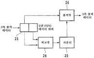
도 5는, 실시예 1에서의 3축 출력 데이터 선택의 구체적 방법(그 1)을 도시 하는 블록도로서, 데이터 기억부(12)와 데이터 선택부(13)의 상세를 도시한 것이다. 도면 내 부호 23은 2단 FIFO형 데이터 버퍼, 24는 비교부, 25는 카운터, 26은 출력부를 나타내고 있다.FIG. 5 is a block diagram showing a specific method (three) of three-axis output data selection in the first embodiment, showing details of the
2단 FIFO형 데이터 버퍼(23)는, 데이터 기억부(12)에 상당하고, 감도 보정 계산부(11)로부터 축차적으로 출력되는 3축 출력 데이터를 기억한다. 비교부(24)는, 2단 FIFO형 데이터 버퍼(23)의 각 단에 기억되어 있는 3축 출력 데이터끼리의 차분을 계산하여, 소정치 이상이면 카운터(25)를 클리어, 소정치 미만이면 카운터(25)의 값을 1개 늘린다.The two-stage FIFO
카운터(25)의 값이 소정치, 예를 들면, 3 이상으로 되면 출력부(26)가 기동하고, 2단 FIFO형 데이터 버퍼(23)의 초단에 저장되어 있는 3축 출력 데이터를 선택된 3축 출력 데이터로서 출력한다.When the value of the
<구체적 방법(그 2)><Specific method (2)>
데이터 선택부(13)는, 데이터 취득부(5A)에 의해 반복 취득된 소정 수의 3축 출력 데이터의, 각 축 성분을 좌표치로 했을 때의 3차원 직교 좌표 공간에서의 분포에 기초하여 구면을 추정하고, 이 구면으로부터 소정 거리 이내에 있는 3축 출력 데이터를 적당하다고 판단하여 선택한다.The
가속도 계측 장치가 운동 가속도를 받고 있는 동안에 취득된 3축 출력 데이터는, 도 2와 같이, 3차원 직교 좌표 공간(x, y, z)에서 3축 출력 데이터의 각 축 성분을 좌표치로 하는 점 P(Sx, Sy, Sz)로서 나타낸 경우, 운동 가속도가 커질수록 기준점 C1(Cx, Cy, Cz)로부터의 거리가 ag로부터 벗어날 가능성이 높아진다.The three-axis output data acquired while the acceleration measuring device is receiving the movement acceleration is a point P that uses each axis component of the three-axis output data in the three-dimensional Cartesian coordinate space (x, y, z) as shown in FIG. In the case of (Sx, Sy, Sz), the greater the acceleration of movement, the higher the possibility that the distance from the reference point C1 (Cx, Cy, Cz) deviates from ag.
기준점 추정부(15)에서의 기준점 좌표의 추정에서는, 기준점 C1(Cx, Cy, Cz)부터 점 P(Sx, Sy, Sz)까지의 거리가 ag로부터 크게 벗어나는 3축 출력 데이터가 포함되면 추정 오차가 커진다.In the estimation of the reference point coordinates in the reference
도 6은, 실시예 1에서의 3축 출력 데이터 선택의 구체적 방법 2의 개념도이며, 전술한 경향에 기초한 3축 출력 데이터의 구체적 선택 방법을 설명하기 위한 것이다. 여기에서는 설명을 간단하게 하기 위해서 2차원으로 나타내고 있다.FIG. 6 is a conceptual diagram of a
데이터 기억부(12)에 유지되고 있는 최신의 소정 수, 예를 들면, 8개의 3축 출력 데이터를, 3차원 직교 좌표 공간(x, y, z)에서 각각 3축 출력 데이터의 각 축 성분을 좌표치로 하는 점 P1(S1x, S1y, S1z), P2(S2x, S2y, S2z), …, P8(S8x, S8y, S8z)로서 나타냈을 때, 이들 점의 분포에 적용되는 구면 Q1을 추정한다.The latest predetermined number, for example, eight three-axis output data held in the
구면 Q1로부터, 소정 거리 Δr 이내에 존재하는 P1, P2, P3, P5, P7, P8에 대응하는 3축 출력 데이터를, 선택된 3축 출력 데이터로서 출력한다.From the spherical surface Q1, triaxial output data corresponding to P1, P2, P3, P5, P7, and P8 existing within a predetermined distance Δr is output as the selected triaxial output data.
구면 Q1을 추정하는 구체적 방법에 대해서는, 예를 들면, 후술하는 방법을 적용할 수 있다. 또한, 예를 들면, 보정된 감도 a가 명확하게 정해지는 경우에는, 구면 Q1의 반경 r을 소정치로 하여 구면 Q1을 추정하여도 된다.As a specific method of estimating spherical surface Q1, the method mentioned later can be applied, for example. For example, when the corrected sensitivity a is clearly determined, the spherical surface Q1 may be estimated with the radius r of the spherical surface Q1 as a predetermined value.
다음으로, 데이터 축적부(14)와 데이터 변화 판정부(18)에 대하여 설명한다.Next, the
데이터 선택부(13)에 의해 선택된 3축 출력 데이터가, 데이터 축적부(14)에 의해 이미 축적된 3축 출력 데이터와 비교하여 소정치 이상 변화되었는지의 여부를 판정하는 데이터 변화 판정부(18)를 구비하고, 데이터 축적부(14)는, 데이터 변화 판정부(18)의 판정 결과에 기초하여, 데이터 선택부(13)에 의해 선택된 3축 출력 데이터를 축적하지 않고 폐기한다.The data change
데이터 축적부(14)에 축적된 3축 가속도 데이터를, 3차원 직교 좌표 공간(x, y, z)에서 3축 출력 데이터의 각 축 성분을 좌표치로 하는 점 P1(S1x, S1y, S1z), P2(S2x, S2y, S2z), …PN(SNx, SNy, SNz)로서 나타냈을 때에, 각 점이 좁은 영역에 집중되어 있으면, 기준점 추정부(15)에서 기준점 좌표의 추정 오차가 매우 커지는 문제가 발생한다.The point P1 (S1x , S1y ,) in which the three-axis acceleration data accumulated in the
이것은, 3축 가속도 센서(1)가 동일한 자세에 있을 때에 취득된 3축 가속도 데이터만이 데이터 축적부(14)에 축적되어 있는 것에 상당한다.This corresponds to the fact that only the 3-axis acceleration data acquired when the 3-
전술한 문제를 피하기 위해, 데이터 선택부(13)에서 선택된 3축 출력 데이터를 데이터 축적부(14)에 축적하기 전에, 이미 데이터 축적부(14)에 축적되어 있는 3축 출력 데이터와 비교하여, 소정치 이상 변화되지 않으면 어느 한 쪽을 축적하지 않고 폐기하도록 하면 된다.In order to avoid the above-mentioned problem, before accumulating the three-axis output data selected by the
이것은, 데이터 선택부(13)에서 선택된 3축 출력 데이터가 취득되었을 때의 3축 가속도 센서(1)의 자세가, 이미 데이터 축적부(14)에 축적되어 있는 3축 출력 데이터가 취득되었을 때의 3축 가속도 센서(1)의 자세와 비교하여 그다지 변화되지 않으면, 어느 한 쪽의 3축 출력 데이터를 축적하지 않고 폐기하는 것에 상당한다.This is because the attitude of the three-
도 7은, 실시예 1에서의 데이터 변화 판정부의 구체적인 구성도로, 데이터 축적부(14)를 도시한 것이다. 도 7에서 부호 27은 입력부, 28은 비교부, 29는 데 이터 버퍼, 30은 출력부를 나타내고 있다.FIG. 7 shows the
데이터 선택부(13)에서 선택된 3축 출력 데이터는 일단 입력부(27)에서 일시 기억된다. 비교부(28)는 입력부(27)에서 일시 기억되어 있는 3축 출력 데이터와, 데이터 버퍼(29)에 축적되어 있는 3축 출력 데이터와 비교하여, 양자의 차분이 소정치 이상인지의 여부를 판단한다. 또한 비교 대상으로 되는 데이터 버퍼(29)에 축적되어 있는 3축 출력 데이터는, 상황에 따라서, 마지막으로 축적된 3축 출력 데이터만이어도 되고, 모든 3축 출력 데이터와 각각 비교하는 것으로 하여도 된다.The three-axis output data selected by the
비교부(28)에서의 3축 출력 데이터의 비교 결과, 그 차분이 소정치 이상이면 입력부(27)에서 일시 기억되어 있는 3축 출력 데이터를 데이터 버퍼(29)에 축적하고, 그 차분이 소정치 미만이면 입력부(27)에서 일시 기억되어 있는 3축 출력 데이터는 파기된다. 혹은, 비교 대상으로 된 데이터 버퍼(29)에 축적되어 있는 3축 출력 데이터를 삭제하고, 입력부(27)에서 일시 기억되어 있는 3축 출력 데이터를 데이터 버퍼(29)에 축적하여도 된다. 출력부(30)는, 데이터 버퍼(29)에 축적되어 있는 3축 출력 데이터를 기준점 추정부(15)를 향하여 출력한다.As a result of the comparison of the three-axis output data in the
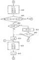
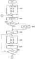
도 8 내지 도 10은, 본 발명의 실시예 1에서의 기준점 좌표 데이터를 취득하는 수순을 설명하기 위한 플로우차트를 도시하는 도면이다. 또한, 여기에서는, 데이터 변화 판정부(18)에서, 데이터 선택부(13)에서 선택된 3축 출력 데이터와 데이터 축적부(14)에 마지막으로 축적되어 있는 3축 출력 데이터를 비교하여, 양자의 차분이 소정치 미만이면 전자가 파기되는 것으로 하고 있다.8 to 10 are flowcharts for explaining a procedure for acquiring reference point coordinate data according to the first embodiment of the present invention. Here, in the data change
우선, 초기 설정으로서 이하의 조작을 행한다(S101). 데이터 기억부(12)의 카운터 k1(도 5의 카운터(25)에 상당)을 클리어한다. 다음으로, 데이터 축적부(14)에 축적되어 있는 3축 출력 데이터의 수 k2를 클리어한다. 다음으로, 감도 보정 계산부(11)로부터 3축 출력 데이터 Sx, Sy, Sz를 취득하고, 데이터 기억부(12)의 1단째 Sx1, Sy1, Sz1에 기억한다.First, the following operations are performed as initial settings (S101). The counter k1 (corresponding to the
다음으로, 감도 보정 계산부(11)로부터 Sx, Sy, Sz를 취득한다(S102). 다음으로, 데이터 기억부(12)의 Sx1, Sy1, Sz1에 기억되어 있는 3축 출력 데이터를 데이터 기억부(12)의 2단째 Sx2, Sy2, Sz2에 보내고, Sx, Sy, Sz를 Sx1, Sy1, Sz1에 기억한다(S103).Next, Sx, Sy, and Sz are acquired from the sensitivity correction calculation part 11 (S102). Next, the 3-axis output data stored in Sx1 , Sy1 , Sz1 of the
다음으로, 데이터 기억부(12) 내의 1단째와 2단째에 각각 기억되어 있는 3축 출력 데이터의 차분이 소정치 e1 이상인 경우에는 k1을 클리어하고 스텝 S102로 되돌아간다(S104, S105). 다음으로, k1의 값을 1개 늘리고(S106), k1의 값이 소정치 m1 미만인 경우에는, S102로 되돌아간다(S107).Next, when the difference between the three-axis output data stored in the first stage and the second stage in the
다음으로, k1을 클리어하고, Sx1, Sy1, Sz1을 데이터 선택부(13)의 출력 Sxo, Syo, Szo(도 5의 출력부(26)에 보내는 것에 상당)로 한다(S108). 다음으로, Sxo, Syo, Szo와 데이터 축적부(14)의 1단째에 기억되어 있는 3축 출력 데이터 S1x, S1y, S1z의 차분이 소정치 e2 미만인 경우에는 S102로 되돌아간다(S109). k2의 값이 소정치 N 이상인 경우에는, S113으로 진행한다(S110). k2의 값을 1개 늘리고(S111), k2의 값이 1인 경우에는, S117로 진행한다(S112).Next, k1 is cleared, and Sx1 , Sy1 , and Sz1 are output Sxo , Syo , and Szo (corresponding to the
다음으로, 지표 i를 k2의 값으로 설정한다(S113). 지표 j를 i-1로 설정하고, 데이터 축적부(14)의 j단째 Sjx, Sjy, Sjz에 기억되어 있는 3축 출력 데이터를 i단째 Six, Siy, Siz에 보낸다(114). i의 값을 1개 줄이고(S115), i의 값이 1을 초과하는 경우에는, S114로 되돌아간다(S116).Next, the index i is set to the value of k2 (S113). The index j is set to i-1, and the 3-axis output data stored in the j stages Sjx , Sjy , and Sjz of the
다음으로, Sxo, Syo, Szo를 S1x, S1y, S1z에 기억한다(S117). k2의 값이 N 미만인 경우에는, S102로 되돌아간다(S118). (S1x, S1y, S1z), …, (SNx, SNy, SNz)로부터 Cx', Cy', Cz'를 추정한다(S119). Cx', Cy', Cz'의 추정을 반복하는 경우에는, S102로 되돌아간다(S120).Next, Sxo , Syo , and Szo are stored in S1x , S1y , and S1z (S117). When the value of k2 is less than N, it returns to S102 (S118). (S1x , S1y , S1z ),. , Cx ', Cy', Cz 'are estimated from (SNx , SNy , SNz ) (S119). When the estimation of Cx ', Cy', and Cz 'is repeated, the process returns to S102 (S120).
(실시예 2)(Example 2)
도 11은, 본 발명의 가속도 계측 장치의 실시예 2를 설명하기 위한 구성도이며, 기준점의 추정으로서, 3차원 직교 좌표 공간 상에 타원면을 정하여 주축의 길이 및 중심 좌표치의 추정을 행함으로써 감도와 오프셋의 보정을 행하는 것이다.Fig. 11 is a configuration diagram for explaining the second embodiment of the acceleration measuring apparatus of the present invention. As an estimation of a reference point, an ellipsoid is determined on a three-dimensional rectangular coordinate space to estimate the length and center coordinate values of the principal axis. The offset is corrected.
도 11에서 부호 31은 3축 가속도 센서, 32는 3축 가속도 센서의 x축 방향 성분 검출 회로, 33은 3축 가속도 센서의 y축 방향 성분 검출 회로, 34는 3축 가속도 센서의 z축 방향 성분 검출 회로, 35A는 데이터 취득부, 35는 멀티플렉서부, 36은 가속도 센서 구동 전원부, 37은 증폭부, 38은 A/D 변환부, 39는 데이터 기억부, 40은 데이터 선택부, 41은 데이터 축적부, 41a는 데이터 변화 판정부, 41b는 온도 검출부, 42는 기준점 추정부, 43은 감도?오프셋 정보 기억부, 44는 감도?오프셋 보정 계산부를 나타내고 있다.In Fig. 11,
본 실시예 2의 가속도 계측 장치는, 3축 방향의 가속도를 검출하는 3축 가속도 센서(31)와, 이 3축 가속도 센서(31)의 3축 출력 데이터를 취득하는 데이터 취득부(35A)와, 이 데이터 취득부(35A)에 의해 반복 취득된 3축 출력 데이터가 적당한지의 여부를 판단하여 선택하는 데이터 선택부(40)와, 이 데이터 선택부(40)에 의해 선택된 3축 출력 데이터를 축적하는 데이터 축적부(41)와, 이 데이터 축적부(41)에 의해 축적된 소정 수의 3축 출력 데이터의, 각 축 성분을 좌표치로 했을 때의 3차원 직교 좌표 공간에서의 분포로부터, 이 3차원 직교 좌표 공간 상에 타원면을 정하고, 타원면의 각 주축의 길이 및 중심 좌표치를 추정하는 기준점 추정부(42)와, 이 기준점 추정부(42)에 의해 추정된 타원면의 각 주축의 길이 및 중심 좌표치에 기초하여, 3축 가속도 센서(31)의 3축 출력 데이터의 감도 및 오프셋을 보정하는 감도?오프셋 보정 계산부(44)를 구비하고 있다. 또한, 데이터 취득부(35A)는, 멀티플렉서부(35)와 가속도 센서 구동 전원부(36)와 증폭부(37)와 A/D 변환부(38)로 구성되어 있다.The acceleration measuring device of the second embodiment includes a three-
3축 가속도 센서(31)와 x축 방향 성분 검출 회로(32)와 y축 방향 성분 검출 회로(33)와 z축 방향 성분 검출 회로(34)와 멀티플렉서부(35)와 가속도 센서 구동 전원부(36)와 증폭부(37)와 A/D 변환부(38)는, 전술한 실시예 1과 마찬가지이다.3-
데이터 기억부(39)는, A/D 변환부(38)로부터 축차적으로 출력되는 3축 출력 데이터를 소정 수 유지하는 FIFO형의 데이터 버퍼이다. 데이터 선택부(40)와 데이터 축적부(41)는, 전술한 실시예 1과 마찬가지이다.The
기준점 추정부(42)는, 데이터 축적부(41)에 축적된 소정 수의 3축 출력 데이 터에 기초하여 타원면의 각 주축의 길이 및 중심 좌표치를 추정하여 타원면 주축 길이?중심 좌표 데이터를 출력한다. 감도?오프셋 정보 기억부(43)는, 기준점 추정부(42)로부터 출력된 타원면 주축 길이?중심 좌표 데이터를 기억한다.The
감도?오프셋 보정 계산부(44)는, 감도?오프셋 정보 기억부(43)에서 기억되어 있는 타원면 주축 길이?중심 좌표 데이터에 기초하여, A/D 변환부(38)로부터 출력된 3축 출력 데이터의 감도 및 오프셋 보정을 행한다.The sensitivity-offset
다음으로, 기준점 추정부(42)에서의 타원면의 각 주축의 길이 및 중심 좌표치를 추정하는 방법에 대하여 설명한다.Next, a method of estimating the length and the center coordinate value of each major axis of the ellipsoid in the reference
A/D 변환부(38)로부터 출력되는 3축 출력 데이터 Srx, Sry, Srz는, 다음 수학식과 같이 표현된다.The 3-axis output data Srx, Sry, and Srz output from the A /


여기서, ax, ay, az는 각 축 방향의 감도, Crx, Cry, Crz는, Srx, Sry, Srz에 존재하는 오프셋을 나타내고 있다.Here, ax , ay , and az represent the sensitivity in each axial direction, and Crx, Cry, and Crz represent offsets present in Srx, Sry, and Srz.
가속도 계측 장치가 정지하고 있다든지, 등속 운동을 행하고 있는 경우, 3축 가속도 센서(1)가 받고 있는 가속도는 중력 가속도 g뿐이다. 따라서,When the acceleration measuring device is stopped or is performing constant velocity motion, the acceleration received by the three-


따라서, 상기 수학식 19로부터Therefore, from Equation 19

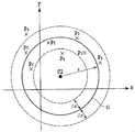
상기 수학식 42에 의하면, 도 12에 도시한 바와 같이, 3차원 직교 좌표 공간(x, y, z)에서 3축 출력 데이터의 각 축 성분을 좌표치로 하는 점 Q(Srx, Sry, Srz)는, ax, ay, az를 각 주축의 길이, Crx, Cry, Crz를 중심 C2의 좌표치로 하여 각 주축의 방향이 3차원 직교 좌표 공간(x, y, z)의 각 축에 평행한 타원면 E1 상에 위치하게 된다.According to
이번에는, N개의 서로 다른 3축 가속도 센서(31)의 자세에서 각각 A/D 변환부(38)로부터 출력되는 3축 출력 데이터를 취득하고, 각 축 성분의 데이터를 각각This time, the three-axis output data output from the A /
S1rx, S2rx, …SNrxS1rx , S2rx ,.. SNrx
S1ry, S2ry, …SNryS1ry , S2ry ,.. SNry
S1rz, S2rz, …SNrzS1rz , S2rz,. SNrz
로 표기한다. 다음으로, 3차원 직교 좌표 공간(x, y, z)에서, 취득한 3축 출력 데이터를It is written as. Next, the three-axis output data acquired in the three-dimensional rectangular coordinate space (x, y, z) is
Q1(S1rx, S1ry, S1rz), Q2(S2rx, S2ry, S2rz), Q3(S3rx, S3ry, S3rz)Q1 (S1rx , S1ry , S1rz ), Q2 (S2rx , S2ry , S2rz ), Q3 (S3rx , S3ry , S3rz )
인 N개의 점으로서 나타내는 것으로 한다.It shall be represented as N points which are.
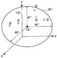
이렇게 하면, 도 13에 도시한 바와 같이, 각 주축의 방향이 3차원 직교 좌표 공간(x, y, z)의 각 축과 평행하고, Q1, Q2, …, QN의 어느 것이나 면 상에 위치하는 타원면 E1'를 추정하면 E1'는 E1에 상당하는 것이 기대되고, E1'의 각 주축의 길이 ax', ay', az'를 가지고 ax, ay, az를, 중심 C2'의 좌표치 Crx', Cry', Crz'를 가지고 Crx, Cry, Crz를 추정할 수 있다.In this way, as shown in FIG. 13, the direction of each major axis is parallel to each axis of the three-dimensional rectangular coordinate space (x, y, z), and Q1 , Q2 ,. , 'When estimating the E1' ellipsoid E1 positioned on whichever side of QN has to be,, E1 'length ax of each principal axis of the "is expected ay', az 'corresponding to the E1 ax , have ay a,z a, the center C2 'coordinate value of the Crx', Cry ', Crz' it is possible to estimate the Crx, Cry, Crz.
<ax', ay', az' 및 Crx', Cry', Crz'를 추정하는 구체적 방법><a',x ay az', 'and Crx', Cry', Crz'reul chujeonghaneun specifically bangbeop>
기준점 추정부(42)는, 타원면의 각 주축의 길이 및 중심 좌표치를, 소정 수의 3축 출력 데이터 각각이 타원면에 가장 근접하도록 통계적 방법에 의해 추정한다.The
Q1, Q2, …, QN로부터 타원 또는 타원면 E1'를 추정하기 위해서는 다양한 방법이 있으며, 최저 N=6에서 추정 가능하다. 그러나, 피에조 저항형 3축 가속도 센서의 감도는 수 백 μV/G/V정도밖에 안되기 때문에 출력 전압은 매우 미약하여, 취 득된 3축 출력 데이터에는 상당한 노이즈가 중첩된다.Q1 , Q2 ,. For estimating an ellipse or
3차원 직교 좌표 공간(x, y, z)에서, i번째의 3축 출력 데이터의 점 Qi(Sirx, Siry, Sirz)부터 E1'까지의 거리 ε는 다음과 같이 된다.3D Cartesian space (x, y, z) in the distance ε from the point Qi (Sirx, Siry,irz S) of the i-th triaxial output data to the E1 'are as follows:

이상적으로는 Q1, Q2, …, QN의 전체에 대하여 εi=0으로 될 것이다. 그러나, 취득된 3축 출력 데이터에는 상당한 노이즈가 중첩되어 있으므로 εi=0으로는 되지 않는다.Ideally Q1 , Q2 ,. Εi = 0 for the whole of QN. However, since considerable noise is superimposed on the obtained three-axis output data, εi = 0 does not become.
따라서 N을 늘리고, εi의 2승 총합치가 최소로 되도록 통계적 방법을 이용하여 ax', ay', az' 및 Crx', Cry', Crz'를 추정하면, 상당한 노이즈가 중첩되어 있더라도 정밀도 높은 추정이 가능해진다.εi의 2승 총합치 Z4는 다음 수학식과 같이 된다.Therefore, if we increase N and estimate ax ', ay ', az 'and Crx', Cry ', Crz' using statistical methods to minimize the sum of squares of εi , Precise estimation is possible. The square sum total value Z4 of εi is given by the following equation.

혹은, εi의 2승 총합치와 유사한 값으로서, 다음 수학식에 의해 Z5를 정의 한다.Alternatively, Z5 is defined by the following equation as a value similar to the sum of squares of εi .

상기 수학식 44 및 45에 대해서는 최적화 방법(예를 들면, 비특허 문헌1 참조)을 이용하여 a'x, a'y, a'z 및 Crx', Cry', Crz'를 계산할 수 있다. 또한, 전술한 실시예 1의 설명에서의 다음 부분은, 모든 실시예 2에서도 마찬가지로 적용 가능하다.For
다음으로, 데이터 선택부(40)에서의 3축 출력 데이터의 선택을 행하는 방법에 대하여 설명한다.Next, a method of selecting triaxial output data by the
<구체적 방법(그 1)><Specific method (1)>
데이터 선택부(40)는, 데이터 취득부(35A)에 의해 3축 출력 데이터를 취득할 때마다 직전에 취득된 3축 출력 데이터와의 차분을 계산하고, 그 차분이 소정 횟수 이상 연속하여 소정치 이내인 경우에, 3축 출력 데이터를 적당하다고 판단하여 선택한다.The
<구체적 방법(그 2)><Specific method (2)>
데이터 선택부(40)는, 데이터 취득부(35A)에 의해 반복 취득된 소정 수의 3축 출력 데이터의, 각 축 성분을 좌표치로 했을 때의 3차원 직교 좌표 공간에서의 분포에 기초하여 구면을 추정하고, 이 구면으로부터 소정 거리 이내에 있는 3축 출 력 데이터를 적당하다고 판단하여 선택한다. 또한, 데이터 선택부(40)는, 구면의 반경을 소정치로 하여 구면을 추정한다.The
다음으로, 데이터 축적부(41)와 데이터 변화 판정부(41a)에 대하여 설명한다.Next, the
데이터 선택부(40)에 의해 선택된 3축 출력 데이터가, 데이터 축적부(41)에 의해 이미 축적된 3축 출력 데이터와 비교하여 소정치 이상 변화되었는지의 여부를 판정하는 데이터 변화 판정부(41a)를 구비하고, 데이터 축적부(41)는, 데이터 변화 판정부(41a)의 판정 결과에 기초하여, 데이터 선택부(40)에 의해 선택된 3축 출력 데이터를 축적하지 않고 폐기한다.The data change
도 14 내지 도 16은, 본 발명의 실시예 2에서 타원면 주축 길이?중심 좌표 데이터를 취득하는 수순을 설명하기 위한 플로우차트를 도시하는 도면이다. 또한, 여기에서는, 데이터 변화 판정부(41a)에서, 데이터 선택부(40)에서 선택된 3축 출력 데이터와 데이터 축적부(41)에 마지막으로 축적되어 있는 3축 출력 데이터를 비교하여, 양자의 차분이 소정치 미만이면 전자가 파기되는 것으로 하고 있다.14 to 16 are flowcharts for explaining a procedure for acquiring ellipsoidal major axis length-center coordinate data in the second embodiment of the present invention. Here, in the data
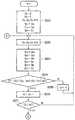
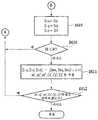
우선, 초기 설정으로서 이하의 조작을 행한다(S201). 데이터 기억부(39)의 카운터 k3(도 5의 카운터(25)에 상당)을 클리어한다. 다음으로, 데이터 축적부(41)에 축적되어 있는 3축 출력 데이터의 수 k4를 클리어한다. 다음으로, A/D 변환부(38)로부터 3축 출력 데이터 Srx, Sry, Srz를 취득하고, 데이터 기억부(39)의 1단째 Srx1, Sry1, Srz1에 기억한다.First, the following operations are performed as initial settings (S201). The counter k3 (corresponding to the
다음으로, A/D 변환부(38)로부터 Srx, Sry, Srz를 취득한다(S202). 다음으로, 데이터 기억부(39)의 Srx1, Sry1, Srz1에 기억되어 있는 3축 출력 데이터를 데이터 기억부(39)의 2단째 Srx2, Sry2, Srz2에 보내고, Srx, Sry, Srz를 Srx1, Sry1, Srz1에 기억한다(S203).Next, Srx, Sry, and Srz are obtained from the A / D converter 38 (S202). Next, the 3-axis output data stored in Srx1 , Sry1 , and Srz1 of the
다음으로, 데이터 기억부(39) 내의 1단째와 2단째에 각각 기억되어 있는 3축 출력 데이터의 차분이 소정치 e3 이상인 경우에는, k3을 클리어하고 스텝 S202로 되돌아간다(S204, S205). k3의 값을 1개 늘리고(S206), k3의 값이 소정치 m2 미만인 경우에는, S202로 되돌아간다(S207). k3을 클리어하고, Srx1, Sry1, Srz1을 데이터 선택부(40)의 출력 Srxo, Sryo, Srzo(도 5의 출력부(26)에 보내는 것에 상당)로 한다(S208).Next, when the difference between the three-axis output data stored in the first and second stages in the
다음으로, Srxo, Sryo, Srzo와 데이터 축적부(41)의 1단째에 기억되어 있는 3축 출력 데이터 S1rx, S1ry, S1rz의 차분이 소정치 e4 미만인 경우에는, S202로 되돌아간다(S209). k4의 값이 소정치 N이상인 경우에는, S213으로 진행한다(S210). k4의 값을 1개 늘리고(S211), k4의 값이 1인 경우에는, S217로 진행한다(S212).Next, in the case of less than Srxo, Sryo, Srzo the
다음으로, 지표 i를 k4의 값으로 설정한다(S213). 지표 j를 i-1로 설정하고, 데이터 축적부(41)의 j단째 Sjrx, Sjry, Sjrz에 기억되어 있는 3축 출력 데이터를 i단째 Sirx, Siry, Sirz에 보낸다(S214). i의 값을 1개 줄이고(S215), i의 값이 1을 초과하는 경우에는, S214로 되돌아간다(S216).Next, the index i is set to the value of k4 (S213). Set the index j to i-1, and sends the 3-axis output data stored in the j-stage Sjrx, Sjry, Sjrz of the
다음으로, Srxo, Sryo, Srzo를 S1rx, S1ry, S1rz에 기억한다(S117). k4의 값이 N 미만인 경우에는, S202로 되돌아간다(S218). (S1rx, S1ry, S1rz), …, (SNrx, SNry, SNrz)로부터 ax', ay', az' 및 Crx', Cry', Crz'를 추정한다(S219). ax', ay', az' 및 Crx', Cry', Crz'의 추정을 반복하는 경우에는, S202로 되돌아간다(S220).Next, the storingrxo S, Sryo, Srzo theS 1rx, S 1ry, S 1rz (S117). If the value of k4 is less than N, the flow returns to S202 (S218). (S1rx , S1ry , S1rz ),. It is estimated from the (SNrx,Nry S, SNrz)x a ',y a',z a 'and Crx', Cry ', Crz' (S219). When the estimation of ax ', ay ', az ', and Crx', Cry ', Crz' is repeated, the process returns to S202 (S220).
(실시예 3)(Example 3)
도 17은, 본 발명의 가속도 계측 장치의 실시예 3을 설명하기 위한 구성도로서, 기준점의 추정을, 3축 가속도 센서가 검지하고 있다고 예상되는 중력 가속도의 각 축 성분의 값으로부터, 3차원 직교 좌표 공간 상에 정하는 기준점의 좌표치를 추정하는 것이다.Fig. 17 is a configuration diagram for explaining
도면 내 부호 45는 3축 가속도 센서, 46은 3축 가속도 센서의 x축 방향 성분 검출 회로, 47은 3축 가속도 센서의 y축 방향 성분 검출 회로, 48은 3축 가속도 센서의 z축 방향 성분 검출 회로, 49A는 데이터 취득부, 49는 멀티플렉서부, 50은 가속도 센서 구동 전원부, 51은 증폭부, 52는 A/D 변환부, 53은 온도 검출부, 54는 감도 보정 정보 기억부, 55는 감도 보정 계산부, 56은 기준점 추정부, 57은 오프셋 정보 기억부, 58은 오프셋 보정 계산부를 나타내고 있다. 또한, 전술한 실시예 1과 중복되는 부분은 설명을 생략한다.In the drawing,
본 실시예 3의 가속도 계측 장치는, 3축 방향의 가속도를 검출하는 3축 가속도 센서(45)와, 이 3축 가속도 센서(45)의 3축 출력 데이터를 취득하는 데이터 취득부(49A)와, 3축 가속도 센서(45)가 소정의 한 자세를 유지하고 있는 상태에서 데이터 취득부(49A)에 의해 3축 출력 데이터를 취득하고, 3축 출력 데이터의 각 축 성분을 좌표치로 했을 때의 3차원 직교 좌표 공간에서의 위치 및 소정의 한 자세를 유지하고 있는 상태에서 3축 가속도 센서(45)가 검지하고 있다고 예상되는 중력 가속도의 각 축 성분의 값으로부터, 3차원 직교 좌표 공간 상에 정하는 기준점의 좌표치를 추정하는 기준점 추정부(56)와, 이 기준점 추정부(56)에 의해 추정된 기준점의 좌표치에 기초하여, 3축 가속도 센서(45)의 3축 출력 데이터의 오프셋을 보정하는 오프셋 보정 계산부(58)를 구비하고 있다. 또한, 데이터 취득부(49A)는, 멀티플렉서부(49)와 가속도 센서 구동 전원부(50)와 증폭부(51)와 A/D 변환부(52)로 구성되어 있다.The acceleration measuring device of the third embodiment includes a three-
3축 가속도 센서(45)와 x축 방향 성분 검출 회로(46)와 y축 방향 성분 검출 회로(47)와 z축 방향 성분 검출 회로(48)와 멀티플렉서부(49)와 가속도 센서 구동 전원부(50)와 증폭부(51)와 A/D 변환부(52)와 온도 검출부(53)와 감도 보정 정보 기억부(54)와 감도 보정 계산부(55)와 오프셋 정보 기억부(57)와 오프셋 보정 계산부(58)는, 전술한 실시예 1과 마찬가지이다.3-
기준점 추정부(56)는, 감도 보정 계산부(55)로부터 출력되는 3축 출력 데이터에 기초하여 기준점의 좌표를 추정하여 기준점 좌표 데이터를 출력한다.The
다음으로, 기준점 추정부(56)에서의 기준점의 좌표를 추정하는 방법에 대하여 설명한다.Next, a method of estimating the coordinates of the reference point in the reference
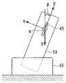
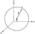
3축 가속도 센서(45)가 기지의 자세로 정지하고 있는 경우, 3축 가속도 센서(45)가 받는 가속도의 각 방향 성분은 일의로 결정된다. 예를 들면, 도 18a 및 도 18b에 도시한 바와 같이, 충전기(60)가 수평으로 놓이고, 가속도 계측 장치(59) 가 소정의 자세로 충전기(60)와 세트되어 있는 상태에서, 3축 가속도 센서(45)의 x축 검출 방향이 중력 가속도 g의 방향에 대하여 수직, y축 검출 방향이 중력 가속도 g의 반대 방향에 대하여 각도 φ 기울어 있다고 하면, 중력 가속도 g의 x, y, z축 방향 성분 Gx, Gy, Gz는 다음과 같이 된다.When the three-


또한, 도 19에 도시한 바와 같이, 3차원 직교 좌표 공간(x, y, z)에서 3축 출력 데이터의 각 축 성분의 오프셋치를 좌표치로 하는 기준점 C1(Cx, Cy, Cz)로부터 3축 출력 데이터의 각 축 성분을 좌표치로 하는 점 P(Sx, Sy, Sz)에 이르는 벡터In addition, as shown in FIG. 19, three-axis output from the reference point C1 (Cx, Cy, Cz) which uses the offset value of each axis component of three-axis output data as a coordinate value in three-dimensional rectangular coordinate space (x, y, z). Vector to point P (Sx, Sy, Sz) with coordinate values of each axis component of data

를 생각한다.Think.
이렇게 하면, 상기 수학식 16, 17, 18로부터,In this way, from

는 다음과 같이 표현된다.Is expressed as

상기 수학식 46, 47, 48로부터 Gx, Gy, Gz는 기지이며, 감도 보정 계산부(55)에서 보정된 감도 a가 계산되면Gx, Gy, and Gz are known from

도 결정된다.Is also determined.
따라서, 다음과 같이 기준점 C1의 좌표치 Cx, Cy, Cz를 계산할 수 있다.Therefore, the coordinate values Cx, Cy, and Cz of the reference point C1 can be calculated as follows.


즉, 가속도 계측 장치가 기지의 자세에서 정지하고 있는 상태가 있다면, 그 상태에서 3축 출력 데이터를 취득하면 간단하게 3축 가속도 센서의 오프셋 데이터를 얻을 수 있다.In other words, if there is a state where the acceleration measuring device is stopped at a known posture, it is possible to simply obtain offset data of the three-axis acceleration sensor by acquiring the three-axis output data in that state.
(실시예 4)(Example 4)
본 실시예 4는, 전술한 실시예 1로부터 다음 수단을 생략한 것으로 되어 있다. 즉, 데이터 선택부(13)에서의 3축 출력 데이터의 선택과 데이터 축적부(14)에서의 데이터 변화 판정부(18)를 생략한 것이다. 가속도 계측 장치의 이용 분야에 따라서는, 예를 들면, 이하의 캐이스도 생각되며, 전술한 수단이 생략 가능하게 되므로 실시예 4를 마련하고 있다.In the fourth embodiment, the following means is omitted from the first embodiment. That is, the selection of the 3-axis output data in the
경사 센서와 같이 중력 가속도의 검출이 주체이고, 또한 계측중에는 가속도 계측 장치가 그다지 움직이지 않고 3축 가속도 센서가 받는 운동 가속도가 중력 가속도에 비하여 극히 작다. 또는, 운동 가속도를 검출하는 수단이 별도로 설치되어 있으며, 운동 가속도가 검출된 경우에는 3축 가속도 데이터를 취득하지 않도록 되어 있다. 기준점 좌표 데이터를 얻기 위한 3축 가속도 데이터 취득 시에는, 개개의 3축 가속도 데이터를 취득할 때마다 사용자가 가속도 계측 장치를 정지시킨 상태에서 3축 가속도 데이터의 취득 지시를 시작하는 조작을 행하도록 되어 있다.Like the inclination sensor, the gravity acceleration is mainly detected, and during the measurement, the acceleration measuring device does not move very much, and the movement acceleration received by the three-axis acceleration sensor is extremely small compared to the gravity acceleration. Alternatively, means for detecting the movement acceleration is provided separately, and the triaxial acceleration data is not acquired when the movement acceleration is detected. At the time of acquiring the 3-axis acceleration data for acquiring the reference point coordinate data, each time the individual 3-axis acceleration data is acquired, the operation of starting the acquisition instruction of the 3-axis acceleration data is performed while the user stops the acceleration measuring device. have.
도 20은, 본 발명의 가속도 계측 장치의 실시예 4를 설명하기 위한 구성도로, 기준점의 추정을, 3차원 직교 좌표 공간 상에 정하는 기준점의 좌표치를 소정 수의 3축 출력 데이터의 각각부터 기준점까지의 거리의 변동이 최소로 되도록 통계적 방법에 의해 추정하는 것이며, 또한, 기준점의 추정을, 3차원 직교 좌표 공간 상에 정하는 기준점의 좌표치를 소정 수의 3축 출력 데이터의 각각부터 기준점까지의 거리가 소정의 대표치에 가장 근접하도록 통계적 방법에 의해 추정하는 것이다.Fig. 20 is a configuration diagram for explaining the fourth embodiment of the acceleration measuring apparatus of the present invention, wherein the coordinate value of the reference point for estimating the reference point is determined from each of a predetermined number of three-axis output data to the reference point. It is estimated by a statistical method so that the variation of the distance is minimized, and the coordinate value of the reference point determined on the three-dimensional rectangular coordinate space is estimated by the statistical method. It is estimated by a statistical method so as to be closest to a predetermined representative value.
도면 내 부호 61은 3축 가속도 센서, 62는 3축 가속도 센서의 x축 방향 성분 검출 회로, 63은 3축 가속도 센서의 y축 방향 성분 검출 회로, 64는 3축 가속도 센서의 z축 방향 성분 검출 회로, 65A는 데이터 취득부, 65는 멀티플렉서부, 66은 가속도 센서 구동 전원부, 67은 증폭부, 68은 A/D 변환부, 69는 온도 검출부, 70은 감도 보정 정보 기억부, 71은 감도 보정 계산부, 72는 데이터 축적부, 73은 기준점 추정부, 74는 오프셋 정보 기억부, 75는 오프셋 보정 계산부를 나타내고 있다.In the drawing,
본 실시예 4의 가속도 계측 장치는, 3축 방향의 가속도를 검출하는 3축 가속도 센서(61)와, 이 3축 가속도 센서(61)의 3축 출력 데이터를 취득하는 데이터 취득부(65A)와, 이 데이터 취득부(65A)에 의해 반복 취득된 소정 수의 3축 출력 데이터의, 각 축 성분을 좌표치로 했을 때의 3차원 직교 좌표 공간에서의 분포로부터, 3차원 직교 좌표 공간 상에 정하는 기준점의 좌표치를 소정 수의 3축 출력 데이터의 각각부터 기준점까지의 거리의 변동이 최소로 되도록 통계적 방법에 의해 추정하는 기준점 추정부(73)와, 이 기준점 추정부(73)에 의해 추정된 기준점의 좌표치에 기초하여, 3축 가속도 센서의 3축 출력 데이터의 오프셋을 보정하는 오프셋 보정 계산부(75)를 구비하고 있다. 또한, 데이터 취득부(65A)는, 멀티플렉서부(65)와 가속도 센서 구동 전원부(66)와 증폭부(67)와 A/D 변환부(68)로 구성되어 있다.The acceleration measuring device according to the fourth embodiment includes a three-
3축 가속도 센서(61)와 x축 방향 성분 검출 회로(62)와 y축 방향 성분 검출 회로(63)와 z축 방향 성분 검출 회로(64)와 멀티플렉서부(65)와 가속도 센서 구동 전원부(66)와 증폭부(67)와 A/D 변환부(68)와 온도 검출부(69)와 감도 보정 정보 기억부(70)와 감도 보정 계산부(71)와 오프셋 정보 기억부(74)와 오프셋 보정 계산부(75)는, 전술한 실시예 1과 마찬가지이다.3-
데이터 축적부(72)는, 감도 보정 계산부(71)로부터 축차적으로 출력되는 3축 출력 데이터를 소정 수 축적하는 데이터 버퍼이다. 기준점 추정부(73)는, 데이터 축적부(72)에 축적된 소정 수의 3축 출력 데이터에 기초하여 기준점의 좌표를 추정해 기준점 좌표 데이터를 출력한다.The data accumulator 72 is a data buffer that accumulates a predetermined number of three-axis output data sequentially output from the
기준점 추정부(73)에서의 기준점의 좌표를 추정하는 방법(그 1)에 대해서는 전술한 실시예 1의 경우와 마찬가지이다.The method (1) for estimating the coordinates of the reference point in the reference
또한, <C1'(Cx', Cy', Cz')를 추정하는 구체적 방법(그 1)>에 대해서도, 전술한 실시예 1의 경우와 마찬가지이다. 즉, 기준점 추정부(73)는, 3차원 직교 좌표 공간 상에 정하는 기준점의 좌표치를 소정 수의 3축 출력 데이터의 각각부터 기준점까지의 거리의 변동이 최소로 되도록 통계적 방법에 의해 추정하는 것이다.In addition, the specific method (part 1) of estimating <C1 '(Cx', Cy ', Cz') is the same as that of the first embodiment described above. That is, the reference
또한, <C1'(Cx', Cy', Cz')를 추정하는 구체적 방법(그 2)>에 대해서도, 전술한 실시예 1의 경우와 마찬가지이다. 즉, 기준점 추정부(73)는, 3차원 직교 좌표 공간 상에 정하는 기준점의 좌표치를 소정 수의 3축 출력 데이터의 각각부터 기준점까지의 거리의 소정의 대표치에 대한 변동이 최소로 되도록 통계적 방법에 의해 추정하는 것이다.In addition, the concrete method (part 2) of estimating <C1 '(Cx', Cy ', Cz') is the same as that of the first embodiment described above. That is, the
도 21 및 도 22는, 본 발명의 실시예 4에서의 기준점 좌표 데이터를 취득하는 수순을 설명하기 위한 플로우차트를 도시하는 도면이다.21 and 22 are flowcharts for explaining a procedure for acquiring reference point coordinate data in the fourth embodiment of the present invention.
우선, 초기 설정으로서 이하의 조작을 행한다(S301). 감도 보정 계산부(71)로부터 3축 출력 데이터 Sx, Sy, Sz를 취득하고, 데이터 축적부(72)의 1단째 S1x, S1y, S1z에 기억한다. 다음으로, 데이터 축적부(72)에 축적되어 있는 3축 출력 데이터의 수 k5를 1로 한다.First, the following operations are performed as initial settings (S301). Sensitivity acquiring triaxial output data Sx, Sy, Sz from the
다음으로, 감도 보정 계산부(71)로부터 Sx, Sy, Sz를 취득한다(S302). k5의 값이 소정치 N 미만인 경우에는 k5의 값을 1개 늘린다(S303, S304). 지표 i를 k5의 값으로 설정한다(S305). 지표 j를 i-1로 설정하고, 데이터 축적부(72)의 j단째 Sjx, Sjy, Sjz에 기억되어 있는 3축 출력 데이터를 i단째 Six, Siy, Siz에 보낸다(S306). i의 값을 1개 줄이고(S307), i의 값이 1을 초과하는 경우에는, S306으로 되돌아간다(S116).Next, Sx, Sy, and Sz are acquired from the sensitivity correction calculation part 71 (S302). If the value of k5 is less than the predetermined value N, one value of k5 is increased (S303, S304). The index i is set to a value of k5 (S305). The index j is set to i-1, and the 3-axis output data stored in the j stages Sjx , Sjy , and Sjz of the
다음으로, Sx, Sy, Sz를 S1x, S1y, S1z에 기억한다(S309). k5의 값이 N 미만인 경우에는, S302로 되돌아간다(S310). (S1x, S1y, S1z), …, (SNx, SNy, SNz)로부터 Cx', Cy', Cz'를 추정한다(S311). Cx', Cy', Cz'의 추정을 반복하는 경우에는, S302로 되돌아간다(S312).Next, it stores the Sx, Sy, Sz theS 1x, S 1y, S 1z (S309). If the value of k5 is less than N, the flow returns to S302 (S310). (S1x , S1y , S1z ),. , Cx ', Cy', and Cz 'are estimated from (SNx , SNy , SNz ) (S311). When the estimation of Cx ', Cy', and Cz 'is repeated, the process returns to S302 (S312).
(실시예 5)(Example 5)
본 실시예 5는, 전술한 실시예 2로부터 다음 수단을 생략한 것으로 되어 있다. 즉, 데이터 선택부(40)에서의 3축 출력 데이터의 선택과 데이터 축적부(41)에서의 데이터 변화 판정부(41a)를 생략한 것이다.In the fifth embodiment, the following means is omitted from the second embodiment. That is, the selection of the 3-axis output data in the
실시예 4의 설명에서 기재한 바와 같이, 가속도 계측 장치의 이용 분야에 따라서는, 전술한 수단이 생략 가능하게 되는 경우도 생각되어지므로, 실시예 5를 마련하고 있다.As described in the description of the fourth embodiment, according to the field of use of the acceleration measuring device, it is possible to omit the above-described means, and therefore, the fifth embodiment is provided.
도 23은, 본 발명의 가속도 계측 장치의 실시예 5를 설명하기 위한 구성도로서, 기준점의 추정을, 3차원 직교 좌표 공간 상에 정하는 타원면의 각 주축의 길이 및 중심 좌표치를 소정 수의 3축 출력 데이터 각각이 타원면에 가장 근접하도록 통계적 방법에 의해 추정하는 것이다.Fig. 23 is a configuration diagram for explaining the fifth embodiment of the acceleration measuring apparatus of the present invention, wherein the length and the center coordinate value of each major axis of an ellipsoid in which the estimation of the reference point is determined on the three-dimensional rectangular coordinate space are three axes of predetermined numbers. It is estimated by a statistical method so that each of the output data is closest to the ellipsoid.
도 23에서 부호 76은 3축 가속도 센서, 77은 3축 가속도 센서의 x축 방향 성분 검출 회로, 78은 3축 가속도 센서의 y축 방향 성분 검출 회로, 79는 3축 가속도 센서의 z축 방향 성분 검출 회로, 80A는 데이터 취득부, 80은 멀티플렉서부, 81은 가속도 센서 구동 전원부, 82는 증폭부, 83은 A/D 변환부, 84는 데이터 축적부, 85는 기준점 추정부, 86은 감도?오프셋 정보 기억부, 87은 감도?오프셋 보정 계산부를 나타내고 있다.In Fig. 23,
본 실시예 5의 가속도 계측 장치는, 3축 방향의 가속도를 검출하는 3축 가속도 센서(76)와, 이 3축 가속도 센서(76)의 3축 출력 데이터를 취득하는 데이터 취득부(80A)와, 이 데이터 취득부(80A)에 의해 반복 취득된 소정 수의 3축 출력 데이터의, 각 축 성분을 좌표치로 했을 때의 3차원 직교 좌표 공간에서의 분포로부터, 3차원 직교 좌표 공간 상에 정하는 타원면의 각 주축의 길이 및 중심 좌표치를 소정 수의 3축 출력 데이터 각각이 타원면에 가장 근접하도록 통계적 방법에 의해 추정하는 기준점 추정부(85)와, 이 기준점 추정부(85)에 의해 추정된 타원면의 각 주축의 길이 및 중심 좌표치에 기초하여, 3축 가속도 센서의 3축 출력 데이터의 감도 및 오프셋을 보정하는 감도?오프셋 보정 계산부(87)를 구비하고 있다. 또한, 데이터 취득부(80A)는, 멀티플렉서부(80)와 가속도 센서 구동 전원부(81)와 증폭부(82)와 A/D 변환부(83)로 구성되어 있다.The acceleration measuring device according to the fifth embodiment includes a three-
3축 가속도 센서(76)와 x축 방향 성분 검출 회로(77)와 y축 방향 성분 검출 회로(78)와 z축 방향 성분 검출 회로(79)와 멀티플렉서부(80)와 가속도 센서 구동 전원부(81)와 증폭부(82)와 A/D 변환부(83)는, 전술한 실시예 1과 마찬가지이다.3-
데이터 축적부(84)는, A/D 변환부(83)로부터 축차적으로 출력되는 3축 출력 데이터를 소정 수 축적하는 데이터 버퍼이다. 기준점 추정부(85)는, 데이터 축적부(84)에 축적된 소정 수의 3축 출력 데이터에 기초하여 타원면의 각 주축의 길이 및 중심 좌표치를 추정하여 타원면 주축 길이?중심 좌표 데이터를 출력한다. 감도?오프셋 정보 기억부(86)와 감도?오프셋 보정 계산부(87)에 대해서는, 전술한 실시예 2의 경우와 마찬가지이다.The data accumulator 84 is a data buffer that accumulates a predetermined number of three-axis output data sequentially output from the A /
또한, 기준점 추정부(85)에서의 타원면의 각 주축의 길이 및 중심 좌표치를 추정하는 방법에 대해서도, 전술한 실시예 2의 경우와 마찬가지이다.In addition, the method of estimating the length and center coordinate value of each main axis of an ellipsoid by the reference
또한, <ax', ay', az' 및 Crx', Cry', Crz'를 추정하는 구체적 방법>에 대해서도, 전술한 실시예 2의 경우와 마찬가지이다.In addition, the <ax ', ay ', az 'and the specific method of estimating Crx', Cry ', and Crz' are the same as in the case of Example 2 described above.
도 24 및 도 25는, 본 발명의 실시예 5에서의 기준점 좌표 데이터를 취득하는 수순을 설명하기 위한 플로우차트를 도시하는 도면이다.24 and 25 are flowcharts for explaining the procedure for acquiring reference point coordinate data in the fifth embodiment of the present invention.
우선, 초기 설정으로서 이하의 조작을 행한다(S401). A/D 변환부(83)로부터 3축 출력 데이터 Srx, Sry, Srz를 취득하고, 데이터 축적부(84)의 1단째 S1rx, S1ry, S1rz에 기억한다. 다음으로, 데이터 축적부(84)에 축적되어 있는 3축 출력 데이터 의 수 k6을 1로 한다.First, the following operations are performed as initial settings (S401). The 3-axis output data Srx, Sry, and Srz are obtained from the A /
다음으로, A/D 변환부(83)로부터 Srx, Sry, Srz를 취득한다(S402). k6의 값이 소정치 N 미만인 경우에는 k6의 값을 1개 늘린다(S403, S404). 지표 i를 k6의 값으로 설정한다(S405). 지표 j를 i-1로 설정하고, 데이터 축적부(84)의 j단째 Sjrx, Sjry, Sjrz에 기억되어 있는 3축 출력 데이터를 i단째 Sirx, Siry, Sirz에 보낸다(S406). i의 값을 1개 줄이고(S407), i의 값이 1을 초과하는 경우에는, S406으로 되돌아간다(S216).Next, Srx, Sry, and Srz are obtained from the A / D converter 83 (S402). If the value of k6 is less than the predetermined value N, the value of k6 is increased by one (S403, S404). The index i is set to a value of k6 (S405). Set the index j to i-1, and sends the 3-axis output data stored in the j-stage Sjrx, Sjry, Sjrz of the
다음으로, Srx, Sry, Srz를 S1rx, S1ry, S1rz에 기억한다(S409). k6의 값이 N 미만인 경우에는, S402로 되돌아간다(S410). (S1rx, S1ry, S1rz), …, (SNrx, SNry, SNrz)로부터 ax', ay', az' 및 Crx', Cry', Crz'를 추정한다(S411). ax', ay', az' 및 Crx', Cry', Crz'의 추정을 반복하는 경우에는, S402로 되돌아간다(S412).Next, Srx , Sry , and Srz are stored in S1rx , S1ry , and S1rz (S409). If the value of k6 is less than N, the flow returns to S402 (S410). (S1rx , S1ry , S1rz ),. It is estimated from the (SNrx,Nry S, SNrz)x a ',y a',z a 'and Crx', Cry ', Crz' (S411). If the estimation of ax ', ay ', az 'and Crx', Cry ', Crz' is repeated, the process returns to S402 (S412).
다음으로, 온도 특성에의 대응에 대하여 설명한다.Next, the correspondence to temperature characteristics is demonstrated.
전술한 바와 같이, 피에조 저항형의 가속도 센서에서는 감도 및 오프셋은 현저한 온도 특성을 가진다. 따라서, 가속도 계측 장치가 놓여 있는 환경의 온도 변화가 큰 경우에는, 오프셋 정보 기억부에 기억된 기준점 좌표 데이터의 추정에 이용된 3축 가속도 데이터가 취득되었을 때의 온도, 혹은 감도?오프셋 정보 기억부에 기억된 타원면 주축 길이?중심 좌표 데이터의 추정에 이용된 3축 가속도 데이터가 취득되었을 때의 온도와, 오프셋 보정 계산부 혹은 감도?오프셋 보정 계산부에서 보정이 대상으로 되는 3축 가속도 데이터가 취득되었을 때의 온도가 크게 상 이하여, 오프셋 보정 혹은 감도?오프셋 보정의 오차가 커질 가능성이 있다.As described above, in the piezoresistive acceleration sensor, the sensitivity and offset have remarkable temperature characteristics. Therefore, when the temperature change of the environment in which the acceleration measuring device is placed is large, the temperature when the three-axis acceleration data used for the estimation of the reference point coordinate data stored in the offset information storage unit or the sensitivity and offset information storage unit is acquired. The temperature at which the 3-axis acceleration data used for the estimation of the ellipsoidal spindle axis length and the center coordinate data stored in the data is obtained, and the 3-axis acceleration data to be corrected by the offset correction calculation unit or the sensitivity offset offset calculation unit is acquired. The temperature at the time of use becomes largely different, and there exists a possibility that the error of offset correction or a sensitivity offset offset may become large.
또한, 기준점 좌표 데이터의 추정에 이용되는 소정 수의 3축 가속도 데이터가 각각 취득되었을 때의 온도의 변동, 혹은 타원면 주축 길이?중심 좌표 데이터의 추정에 이용되는 소정 수의 3축 가속도 데이터가 각각 취득되었을 때의 온도의 변동이 커져, 기준점 좌표 데이터 혹은 타원면 주축 길이?중심 좌표 데이터의 오차가 커질 가능성도 있다.In addition, a predetermined number of three-axis acceleration data used for estimating the predetermined number of three-axis acceleration data used for the estimation of the reference point coordinate data or an ellipsoidal main axis length and the center coordinate data are respectively acquired. When the temperature fluctuates, the fluctuation of the temperature may increase, and the error between the reference point coordinate data or the ellipsoidal main axis length and the center coordinate data may increase.
이하, 전술한 실시예 1 내지 실시예 5에서 적용 가능한, 전술한 온도 특성에의 대응에 대한 각 해결 수단에 대하여 설명한다.Hereinafter, each solution means for responding to the above-described temperature characteristic applicable to the above-described first to fifth embodiments will be described.
<해결 수단 1><
본 해결 수단 1은, 전술한 실시예 1, 2, 4 및 5에서 적용 가능하다.This
이하, 실시예 1에 적용하는 경우에 대하여 설명한다.Hereinafter, the case where it applies to Example 1 is demonstrated.
도 26은, 온도 특성에의 대응에 대한 해결 수단 1을 도시하는 블록도이며, 도 26에서 부호 88은 입력부, 89는 비교부, 90은 제1 데이터 버퍼, 91은 제2 데이터 버퍼, 92는 데이터 버퍼 L, 93은 선택부, 94는 기준점 추정부, 95는 분배부, 96은 제1 기준점 좌표 기억, 97은 제2 기준점 좌표 기억, 98은 기준점 좌표 기억 L을 나타내고 있다. 즉, 도 26은, 본 해결 수단을 적용한 경우의, 데이터 축적부(14)와 기준점 추정부(15) 및 오프셋 정보 기억부(16)에 상당하는 상세 구성의 일례를 도시한 것이다.Fig. 26 is a block diagram showing a
가속도 계측 장치의 사용 온도 범위는, 미리 L개로 구분되어 있고, 각각 온도 구분 1, 온도 구분 2, …, 온도 구분 L로 칭하는 것으로 한다. 데이터 선택 부(13)에서 선택된 3축 출력 데이터는, 일단 입력부(88)에서 일시 기억된다. 입력부(88)는, 온도 검출부(9)로부터 취득된 온도 데이터에 기초하여, 일시 기억된 3축 출력 데이터가 어느 온도 구분에 속하는지를 결정한다.The temperature range of use of the acceleration measuring device is divided into L pieces in advance, and
제1 데이터 버퍼(90)와 제2 데이터 버퍼(91), …, 데이터 버퍼 L(92)은, 각각 온도 구분 1, 온도 구분 2, …, 온도 구분 L에 속하는 3축 출력 데이터를 축적한다.
비교부(89)는, 제1 데이터 버퍼(90)와 제2 데이터 버퍼(91), …, 데이터 버퍼 L(92) 중에서, 입력부(88)에서 일시 기억된 3축 출력 데이터가 속하는 온도 구분과 동일한 것을 선택한다. 그 후, 전술한 실시예 1의 설명과 마찬가지로, 입력부(88)에서 일시 기억된 3축 출력 데이터를 선택된 데이터 버퍼에 축적한다든지 파기한다.The
선택부(93)는, 입력부(88)에서 일시 기억된 3축 출력 데이터가 비교부(89)에 의해 선택된 데이터 버퍼에 축적되었을 때, 선택된 데이터 버퍼에 축적된 데이터 수가 소정 수에 도달해 있으면, 선택된 데이터 버퍼에 축적되어 있는 3축 출력 데이터와 온도 구분 정보를 기준점 추정부(94)를 향하여 출력한다.When the three-axis output data temporarily stored in the
기준점 추정부(94)는, 선택부(93)로부터 출력된 3축 출력 데이터에 기초하여 기준점의 좌표치를 추정한다. 분배부(95)는, 선택부(93)로부터 출력된 온도 구분 정보에 기초하여, 기준점 추정부(94)로부터 출력된 기준점 좌표 데이터를 대응하는 제1 기준점 좌표 기억(96)과 제2 기준점 좌표 기억(97), …, 기준점 좌표 기억 L(98) 중 어느 하나에 기억한다.The
또한, 입력부(88)에서 일시 기억된 3축 출력 데이터를 비교부(89)에 의해 선택된 데이터 버퍼에 축적할 때, 온도 검출부(9)로부터 취득된 온도 데이터가 결정된 온도 구분의 어디에 위치하는지에 의해 3축 출력 데이터를 보정하여도 된다. 이것은, 감도 및 오프셋의 온도 의존성이 대강 파악되어 있고, 더구나, 온도 구분 내에서의 감도 및 오프셋의 온도 변화가 비교적 큰 경우에 유효하다.When the 3-axis output data temporarily stored in the
그 후, 오프셋 보정 계산부(17)는, 감도 보정 계산부(11)로부터 출력되는 3축 출력 데이터에 대하여, 온도 검출부(9)로부터 취득한 온도 데이터를 기초로 어느 온도 구분에 속하는지를 결정하고, 대응하는 제1 기준점 좌표 기억(96)과 제2 기준점 좌표 기억(97), …, 기준점 좌표 기억 L(98) 중 어느 하나에 기억되어 있는 기준점 좌표 데이터를 이용하여 오프셋 보정을 행한다.Thereafter, the offset
<해결 수단 2><
본 해결 수단 2는, 전술한 실시예 1, 2, 4 및 5에서 적용 가능하다. 이하, 실시예 1에 적용하는 경우에 대하여 설명한다.This
도 27은, 온도 특성에의 대응에 관한 해결 수단 2를 도시하는 블록도로서, 본 해결 수단을 적용한 경우의, 데이터 축적부(14, 40)와 기준점 추정부(15, 42) 및 오프셋 정보 기억부(16), 감도?오프셋 정보 기억부(43)에 상당하는 상세 구성의 일례를 도시한 것이다. 도면 내 부호 99는 입력부, 100은 비교부, 101은 데이터 버퍼 A, 102는 데이터 버퍼 B, 103은 선택부, 104는 기준점 추정부, 105는 분배부, 106은 제1 기준점 좌표 기억, 107은 제2 기준점 좌표 기억, 108은 기준점 좌표 기억 L을 나타내고 있다.Fig. 27 is a block
가속도 계측 장치의 사용 온도 범위는, 미리 L개로 구분되어 있고, 각각 온도 구분 1, 온도 구분 2, …, 온도 구분 L로 칭하는 것으로 한다.The temperature range of use of the acceleration measuring device is divided into L pieces in advance, and
데이터 선택부(13)에서 선택된 3축 출력 데이터는, 일단 입력부(99)에서 일시 기억된다. 입력부(99)는, 온도 검출부(9)로부터 취득된 온도 데이터에 기초하여, 일시 기억된 3축 출력 데이터가 어느 온도 구분에 속하는지를 결정한다.The triaxial output data selected by the
데이터 버퍼 A(101)는, 3축 출력 데이터를 축적하고, 데이터 버퍼 B(102)는, 데이터 버퍼 A(101)에 축적된 3축 출력 데이터가 입력부(99)에서 일시 기억되었을 때에 온도 검출부(9)로부터 취득된 온도 데이터를 동일 순서로 축적한다. 그 결과, 데이터 버퍼 A(101)에 축적된 각각의 3축 출력 데이터는, 데이터 버퍼 B(102)에 축적된 온도 데이터를 참조함으로써, 어느 온도 구분에 속하는지를 알 수 있도록 되어 있다.The
비교부(100)는, 입력부(99)에서 일시 기억된 3축 출력 데이터에 대하여, 데이터 버퍼 A(101)에 축적된 3축 출력 데이터 중에서 온도 구분이 동일한 것과 비교함으로써, 전술한 실시예 1의 설명과 마찬가지로, 데이터 버퍼 A(101)에 축적한다든지 파기한다.The
입력부(99)에서 일시 기억된 3축 출력 데이터가, 데이터 버퍼 A(101)에 축적되는 경우, 데이터 버퍼 A(101)에 이미 축적된 3축 출력 데이터 중에서, 금회 축적되려고 하는 3축 출력 데이터와 온도 구분이 동일한 것이 소정 수에 도달해 있는 경우, 해당하는 3축 출력 데이터 중에서 가장 오래된 것과 데이터 버퍼 B(102)에서 대응하는 온도 데이터를 파기한다.When the 3-axis output data temporarily stored in the
입력부(99)에서 일시 기억된 3축 출력 데이터가, 데이터 버퍼 A(101)에 축적되는 경우, 앞서 취득된 온도 데이터를 데이터 버퍼 B(102)에 동시에 축적한다.When the 3-axis output data temporarily stored in the
선택부(103)는, 입력부(99)에서 일시 기억된 3축 출력 데이터가, 데이터 버퍼 A(101)에 축적되었을 때, 데이터 버퍼 A(101)에 축적된 3축 출력 데이터 중에서 금회 축적된 3축 출력 데이터와 온도 구분이 동일한 것이 소정 수에 도달해 있는 경우, 해당하는 3축 출력 데이터와 온도 구분 정보를 기준점 추정부(104)를 향하여 출력한다.The
기준점 추정부(104)는, 선택부(103)로부터 출력된 3축 출력 데이터에 기초하여 기준점의 좌표치를 추정한다. 분배부(105)는, 선택부(103)로부터 출력된 온도 구분 정보에 기초하여, 기준점 추정부(104)로부터 출력된 기준점 좌표 데이터를 대응하는 제1 기준점 좌표 기억(106)과 제2 기준점 좌표 기억(107), …, 기준점 좌표 기억 L(108) 중 어느 하나에 기억한다.The
그 후, 오프셋 보정 계산부(17)는, 감도 보정 계산부(11)로부터 출력되는 3축 출력 데이터에 대하여, 온도 검출부(9)로부터 취득한 온도 데이터를 기초로 어느 온도 구분에 속하는지를 결정하고, 대응하는 제1 기준점 좌표 기억(106)과 제2 기준점 좌표 기억(107), …기준점 좌표 기억 L(108) 중 어느 하나에 기억되어 있는 기준점 좌표 데이터를 이용하여 오프셋 보정을 행한다.Thereafter, the offset
<해결 수단 3><
본 해결 수단 3은, 전술한 실시예 3에서 적용 가능하다.This
도 28은, 온도 특성에의 대응에 대한 해결 수단 3을 도시하는 블록도로서, 본 해결 수단을 적용한 경우의, 오프셋 정보 기억부(57)에 상당하는 상세 구성의 일례를 도시한 것이다. 도 28에서 부호 109는 분배부, 110은 제1 기준점 좌표 기억, 111은 제2 기준점 좌표 기억, 112는 기준점 좌표 기억 L을 나타내고 있다.FIG. 28 is a block
가속도 계측 장치의 사용 온도 범위는, 미리 L개로 구분되어 있고, 각각 온도 구분 1, 온도 구분 2, …, 온도 구분 L로 칭하는 것으로 한다. 분배부(109)는, 온도 검출부(53)로부터 취득된 온도 데이터에 기초하여, 기준점 추정부(56)로부터 출력된 기준점 좌표 데이터를 대응하는 제1 기준점 좌표 기억(110)과 제2 기준점 좌표 기억(111), …, 기준점 좌표 기억 L(112) 중 어느 하나에 기억한다.The temperature range of use of the acceleration measuring device is divided into L pieces in advance, and
그 후, 오프셋 보정 계산부(58)는, 감도 보정 계산부(55)로부터 출력되는 3축 출력 데이터에 대하여, 온도 검출부(53)로부터 취득한 온도 데이터를 기초로 어느 온도 구분에 속하는지를 결정하고, 대응하는 제1 기준점 좌표 기억(110)과 제2 기준점 좌표 기억(111), 기준점 좌표 기억 L(112) 중 어느 하나에 기억되어 있는 기준점 좌표 데이터를 이용하여 오프셋 보정을 행한다.Thereafter, the offset
다음으로, 불량 데이터에의 대응에 대한 각 해결 수단에 대하여 설명한다.Next, each solution means for responding to the defective data will be described.
<해결 수단 1><
본 해결 수단 1은, 전술한 실시예 1, 실시예 2, 실시예 4, 실시예 5에서 적용 가능하다.This
이하, 전술한 실시예 1에 적용하는 경우에 대하여 설명한다.Hereinafter, the case where it applies to Example 1 mentioned above is demonstrated.
양호한 기준점 추정 결과를 얻기 위해서는, 취득한 N개의 3축 출력 데이터의 3차원 직교 좌표 공간(x, y, z)에서의 점 P1(S1x, S1y, S1z), P2(S2x, S2y, S2z), …PN(SNx, SNy, SNz)는 가능한 한 다양한 위치에 골고루 분포되어 있는 것이 바람직하다. 한편, 각 점의 위치는 3축 가속도 센서(1)의 자세에 의해 결정되기 때문에, N개의 3축 출력 데이터의 취득 시에는 가속도 계측 장치의 방향을 가능한 한 다양한 방향으로 골고루 향하는 것이 바람직하게 된다.In order to obtain good reference point estimation results, the points P1 (S1x , S1y , S1z ) and P2 (S2x ,) in the three-dimensional rectangular coordinate space (x, y, z) of the obtained N three-axis output data are obtained. S2y , S2z ),. It is preferable that PN (SNx , SNy , SNz ) be evenly distributed at as many positions as possible. On the other hand, since the position of each point is determined by the attitude of the three-
그런데, 사용자에 따라서는 가속도 계측 장치의 방향의 변화가 한정적으로 되는 경향이 있으며, 이 경우에는 점 P1(S1x, S1y, S1z), P2(S2x, S2y, S2z), …PN(SNx, SNy, SNz)의 분포도 편중되어 양호한 기준점 추정 결과가 얻어지지 않는다.By the way, the change of the direction of the acceleration measuring device tends to be limited depending on the user, in this case, the points P1 (S1x , S1y , S1z ), P2 (S2x , S2y , S2z ) ,… The distribution of PN (SNx , SNy , SNz ) is also biased to obtain a good reference point estimation result.
이 경우, 3축 출력 데이터의 각 축 성분 중에서 가장 값의 변화가 적은 축의 성분을 제외하고, 나머지 2축 성분으로 이루어지는 2축 출력 데이터에 대하여 기준점 좌표의 추정을 행하고, 이 2축에 대하여 오프셋 보정을 행하는 것이 가능하다.In this case, the reference point coordinates are estimated for the two-axis output data consisting of the remaining two-axis components except for the component of the axis having the smallest change in value among the respective axis components of the three-axis output data, and the offset correction is performed for these two axes. It is possible to do
구체적으로는, 이하의 수순으로 행한다.Specifically, the following procedure is performed.
우선, 취득한 N개의 3축 출력 데이터에 대하여, 각 축 성분별로 변동을 계산한다.First, variation is calculated for each axis component with respect to the obtained N three-axis output data.
여기서는 계산의 결과, Z축 성분의 변동 v(z)가 x축 성분의 변동 v(x), y축 성분의 변동 v(y)의 어느 하나로부터도 작아졌다고 가정한다.As a result of the calculation, it is assumed that the variation v (z) of the Z-axis component is smaller from either the variation v (x) of the x-axis component or the variation v (y) of the y-axis component.
다음으로, v(z)가 소정치를 초과하면 통상대로의 기준점 좌표의 추정을 행한다. 다음으로, v(z)가 소정치 이하인 경우, N개의 3축 출력 데이터로부터 z축 성 분의 데이터 S1z, S2z, …SNz를 제외하고, 나머지 X축 성분 데이터 S1x, S2x, …SNx 및 y축 성분의 데이터 S1y, S2y, …SNy로 2축 출력 데이터를 구성한다.Next, when v (z) exceeds a predetermined value, normal reference point coordinates are estimated. Next, when v (z) is less than or equal to a predetermined value, the data S1z , S2z ,... Except SNz , the remaining X-axis component data S1x , S2x ,... SNx and y-axis component data S1y , S2y ,... Configure 2-axis output data with SNy .
다음으로, 2차원 직교 좌표 공간(x, y)에서, 전술한 2축 출력 데이터를Next, in the two-dimensional rectangular coordinate space (x, y), the aforementioned two-axis output data
P1'(S1x, S1y), P2'(S2x, S2y), …PN'(SNx, SNy)P1 ′ (S1x , S1y ), P2 ′ (S2x , S2y ),. PN '(SNx , SNy )
인 N개의 점으로서 나타낸다.It shows as N points which are.
다음으로, 2차원 직교 좌표 공간(x, y)에서, P1', P2', …PN'의 어느 하나로부터도 거리가 일정해지는 점 C1''(Cx'', Cy'')를 추정한다. 다음으로, 점 C1''의 좌표치 Cx'', Cy''를 가지고 3축 출력 데이터 내의 x축 성분 및 x축 성분에 대하여 오프셋 보정을 행한다.Next, in the two-dimensional rectangular coordinate space (x, y), P1 ', P2 ',... The point C1 " (Cx ", Cy ") at which the distance is constant from any of PN 'is estimated. Next, offset correction is performed for the x-axis component and the x-axis component in the 3-axis output data with the coordinate values Cx " and Cy " of the point C1 ".
<해결 수단 2><
본 해결 수단 2는, 전술한 실시예 1 내지 실시예 5에서 적용 가능하다.This
이하, 실시예 1에 적용하는 경우에 대하여 설명한다.Hereinafter, the case where it applies to Example 1 is demonstrated.
전술한 바와 같이, 취득한 N개의 3축 출력 데이터의 3차원 직교 좌표 공간(x, y, z)에서의 점의 분포로부터 추정되는 기준점의 좌표치는 3축 출력 데이터의 오프셋에 상당한다.As described above, the coordinate value of the reference point estimated from the distribution of points in the three-dimensional rectangular coordinate spaces (x, y, z) of the acquired N three-axis output data corresponds to the offset of the three-axis output data.
피에조 저항형의 가속도 센서에서는, 오프셋은 현저한 온도 특성을 가지므로, 가속도 계측 장치가 놓여 있는 환경의 온도 변화가 큰 경우에는 오프셋도 시간 변동한다. 그러나, 단시간에 급격하게 오프셋이 시간 변동하는 것은 피에조 저항형 가속도 센서의 특성상 생각하기 어렵다.In the piezoresistive acceleration sensor, since the offset has a remarkable temperature characteristic, when the temperature change of the environment in which the acceleration measuring device is placed is large, the offset also changes with time. However, it is difficult to think that the offset changes rapidly in a short time due to the characteristics of the piezoresistive acceleration sensor.
이 때문에, 기준점 좌표의 추정을 축차적으로 행하고 있는데, 추정된 기준점 좌표가 단시간에 큰 변동을 일으킨 경우에는, 3축 출력 데이터에 비교적 큰 노이즈가 혼입되었다든지, 3축 출력 데이터 취득중의 가속도 계측 장치의 자세의 변화가 한정적으로 되어 기준점 좌표의 추정이 양호하게 행해지지 않게 될 가능성이 높다.For this reason, although the reference point coordinates are estimated successively, when the estimated reference point coordinates cause large fluctuations in a short time, the relatively large noise is mixed in the three-axis output data or the acceleration measuring device during the three-axis output data acquisition. There is a high possibility that the change in the posture of the position is limited and the estimation of the reference point coordinates is not performed satisfactorily.
또한, 이러한 기준점 좌표를 이용하면, 잘못된 오프셋 보정을 하게 된다. 따라서, 기준점 좌표의 추정에서는, 바로 근처의 소정 수의 기준점 좌표치의 변동을 계산하고, 이 변동이 소정치보다도 크게 된 경우에는 기준점 좌표의 추정이 양호하게 행해지지 않았다고 간주하여, 추정된 기준점 좌표치를 파기하면, 잘못된 오프셋 보정을 막을 수 있다.In addition, using these reference point coordinates, wrong offset correction is performed. Therefore, in the estimation of the reference point coordinates, the variation of the predetermined number of reference point coordinate values is calculated, and when the variation becomes larger than the predetermined value, it is assumed that the estimation of the reference point coordinates has not been performed well, and the estimated reference point coordinate values are calculated. By discarding, incorrect offset correction can be prevented.
<해결 수단 3><
본 해결 수단 3은, 전술한 실시예 1 내지 실시예 5에서 적용 가능하다.The
이하, 전술한 실시예 1에 적용하는 경우에 대하여 설명한다.Hereinafter, the case where it applies to Example 1 mentioned above is demonstrated.
상기 수학식 20으로부터, 3차원 직교 좌표 공간(x, y, z)에서 3축 출력 데이터의 각 축 성분을 좌표치로 하는 점 P(Sx, Sy, Sz)부터 기준점 C1(Cx, Cy, Cz)까지의 거리는 보정된 감도 a와 중력 가속도 g의 곱으로 된다.From the above equation (20), the reference point C1 (Cx, Cy, Cz) from the point P (Sx, Sy, Sz), where each axis component of the 3-axis output data is a coordinate value in the three-dimensional rectangular coordinate space (x, y, z). The distance to is the product of the corrected sensitivity a and the gravitational acceleration g.
피에조 저항형의 가속도 센서에서는, 감도는 현저한 온도 특성을 가지므로, 가속도 계측 장치가 놓여 있는 환경의 온도 변화가 큰 경우에는 감도도 시간 변동하지만, 단시간에 급격하게 감도가 시간 변동하는 것은 피에조 저항형 가속도 센서의 특성상 생각하기 어렵다. 더구나, 실시예 1에서는 감도 보정 계산부(11)에서 감도 보정되고, 보정된 감도 a는 일정에 가깝다.In the piezoresistive acceleration sensor, the sensitivity has a remarkable temperature characteristic. Therefore, when the temperature change of the environment in which the accelerometer is placed is large, the sensitivity also varies with time, but the sensitivity varies rapidly in a short time. It is difficult to think due to the characteristics of the acceleration sensor. Furthermore, in the first embodiment, the sensitivity is corrected in the
중력 가속도 g는 통상의 이용 분야에서 일정치로 간주하여도 된다. 따라서, ag는 미리 예측할 수 있는 값이며, 3차원 직교 좌표 공간(x, y, z)에서 추정된 기준점부터 각 3축 출력 데이터를 나타내는 점까지의 거리도 미리 예측되는 값으로 수렴될 것이다.The gravitational acceleration g may be regarded as a constant value in the general field of use. Therefore, ag is a value that can be predicted in advance, and the distance from the reference point estimated in the three-dimensional rectangular coordinate space (x, y, z) to the point representing each triaxial output data will also converge to the predicted value.
따라서, 기준점 좌표의 추정에서는, 추정된 기준점부터 각 3축 출력 데이터를 나타내는 점까지의 거리의 평균치 등을 계산하고, 이 값이 소정 범위 외인 경우에는 감도 보정 계산부(11)에서의 감도 보정이거나 기준점 좌표의 추정의 어느 한 쪽 혹은 양방이 양호하게 행해지지 않았다고 간주하고, 추정된 기준점 좌표치를 파기하면, 잘못된 오프셋 보정을 막을 수 있다.Therefore, in the estimation of the reference point coordinates, an average value or the like of the distance from the estimated reference point to the point representing each of the three-axis output data is calculated, and when this value is outside the predetermined range, the sensitivity correction is performed in the
다음으로, 2축 가속도 센서에의 적용에 대하여 설명한다.Next, application to a biaxial acceleration sensor will be described.
전술한 실시예 1 내지 실시예 5는, 3축 방향의 가속도를 검출하는 가속도 센서 대신에 2축 방향의 가속도를 검출하는 가속도 센서를 구비한 가속도 계측 장치에 대해서도 적용 가능하다.The first to fifth embodiments described above are also applicable to an acceleration measuring device having an acceleration sensor for detecting acceleration in the two axis direction instead of the acceleration sensor for detecting the acceleration in the three axis direction.
이 때, 실시예 1, 4에서의 기준점 추정 수단에서는, 출력 데이터 축적 수단에 의해 축적된 소정 수의 2축 출력 데이터의 각 축 성분을 좌표치로 했을 때의 2차원 직교 공간에서의 분포로부터, 해당 2차원 직교 공간 상에 정하는 기준점의 좌표를 추정하게 된다.At this time, in the reference point estimating means in Examples 1 and 4, from the distribution in the two-dimensional orthogonal space when each axis component of the predetermined number of biaxial output data accumulated by the output data accumulating means is used as the coordinate value, The coordinates of the reference point determined on the two-dimensional orthogonal space are estimated.
또한, 실시예 2, 5에서의 기준점 추정 수단에서는, 출력 데이터 축적 수단에 의해 축적된 소정 수의 2축 출력 데이터의 각 축 성분을 좌표치로 했을 때의 2차원 직교 공간에서의 분포로부터, 해당 2차원 직교 공간 상에 정하는 타원의 각 주축의 길이 및 중심 좌표치를 추정하게 된다.In addition, in the reference point estimating means in Examples 2 and 5, from the distribution in the two-dimensional orthogonal space when each axis component of the predetermined number of biaxial output data accumulated by the output data accumulating means is used as the coordinate value, the corresponding 2 The length and center coordinate values of each major axis of the ellipse determined on the dimensional orthogonal space are estimated.
또한, 실시예 1, 2, 4, 5의 적용에서는, 기준점의 좌표 또는 타원의 각 주축의 길이 및 중심 좌표치의 추정을 행하기 위한 2축 출력 데이터를 취득하고 있는 동안은, 가속도를 검출하는 2축 방향 중 어느 하나에도 수직한 축의 방향과 중력 가속도의 방향 사이에 이루는 각도가 일정해지도록 가속도 계측 장치의 자세를 제어한다.In addition, in the application of Example 1, 2, 4, 5, 2 which detects acceleration, while acquiring biaxial output data for estimating the coordinate of a reference point or the length and center coordinate value of each main axis of an ellipse, is acquired. The attitude | position of an acceleration measuring device is controlled so that the angle which an angle made between the direction of the axis perpendicular | vertical to any of axial directions, and the direction of gravity acceleration may become constant.
(실시예 6)(Example 6)
3축 가속도 센서에서, 가속도 센서가 중력 가속도만을 받는 경우, 즉, 정지하고 있는 경우의 가속도 센서의 출력 데이터(이하, 측정 데이터라고 함)의 분포는, 3차원 직교 좌표계에서 구면 또는 타원면을 형성한다. 그 때문에, 이 구면 또는 타원면의 중심치를 구함으로써 오프셋을 추정하는 것이 가능하다.In the 3-axis acceleration sensor, the distribution of the output data of the acceleration sensor (hereinafter referred to as measurement data) when the acceleration sensor receives only gravity acceleration, that is, when it is stopped, forms a spherical or ellipsoid in a three-dimensional rectangular coordinate system. . Therefore, the offset can be estimated by obtaining the center value of this spherical or ellipsoidal surface.
가속도 센서의 구면 또는 타원면 적용 계산을 행하기 위해서는, 예를 들면, 측정 데이터를 유한 길이의 버퍼에 축적하고, 축적된 측정치로부터 구체의 중심을 추정하는 방법을 이용할 수 있다. 이 때에 정밀도 있게 구체의 중심을 추정하기 위해서는, 측정 데이터가 구면 상 또는 타원면 상에 신뢰도가 높게 분포되어 있을 필요가 있다. 즉, 측정 데이터는 확실하게 정지했을 때의 데이터이어야 한다.In order to perform spherical or ellipsoidal application calculations of the acceleration sensor, for example, a method of accumulating measurement data in a finite length buffer and estimating the center of the sphere from the accumulated measurement can be used. At this time, in order to accurately estimate the center of the sphere, the measurement data needs to be distributed with high reliability on the spherical surface or the ellipsoidal surface. In other words, the measurement data should be the data when it is stopped.
정지 시의 측정 데이터를 취득하기 위해서는, 가속도 센서가 정지해 있는지의 여부의 판정을 행하는 것이 필요하게 된다. 정지 판정을 행하기 위해서는, 임의의 임계치에 의해 설정된 시간 동안, 측정 데이터가 변화되지 않고 있음을 판정하는 것이 간단하다.In order to acquire the measurement data at the time of stop, it is necessary to determine whether the acceleration sensor is stopped. In order to perform the stop determination, it is simple to determine that the measurement data does not change during the time set by any threshold.
이 설정 시간의 임계치가 작은 경우에는, 우연히도 등가속도 운동으로 된 순간의 값을 취득했을 가능성이 있다. 움직이지 않고 있는 기간의 임계치를 길게 하면, 이러한 우연한 가능성을 낮게 할 수 있지만, 정지 시의 측정 데이터를 취득할 때까지 시간이 걸려, 데이터 취득의 효율이 떨어진다. 따라서, 정지해 있던 시간이 몇 초간이었는가 라고 하는 정지 시간 정보를 정지 시의 측정 데이터에 부가해 놓는 것이 좋다.When the threshold value of this set time is small, it may be possible to acquire the instantaneous value of the instantaneous acceleration motion accidentally. If the threshold value of the non-moving period is made long, this chance of accident can be lowered, but it takes time until the measurement data at the time of acquisition is acquired, and the efficiency of data acquisition is inferior. Therefore, it is better to add the stop time information, such as how many seconds the pause time has been, to the measurement data at the time of stop.
이 정지 시간 정보는, 축적된 측정 데이터가 정지 시의 데이터로서, 어느 정도 신뢰할 수 있는지를 나타내는 하나의 지표로서 이용할 수 있다. 정지해 있었던 시간이 짧은 것은, 데이터 취득 시에 가속도 센서가 정지해 있을 확률이 낮은 것을 나타내고, 반대로 시간이 긴 것은 정지해 있었던 확률이 높은 것을 나타낸다. 이 정지 시간 정보의 사용 방법으로서는, 예를 들면, 이하와 같은 것이 생각된다.This stop time information can be used as one index indicating how reliable the accumulated measurement data is as the data at stop. The short time that has been stopped indicates a low probability that the acceleration sensor is stopped at the time of data acquisition, whereas the long time that has been stopped indicates a high probability that it has stopped. As a usage method of this stop time information, the following are considered, for example.
유한 길이의 버퍼를 이용한 계산을 행하는 경우, 3차원 공간 내에서 가까운 거리에 있는 데이터를 배제함으로써, 버퍼 내의 데이터의 용장이 없어져, 버퍼를 효율적으로 사용할 수 있다. 가까운 거리에 있는 데이터끼리 비교할 때에, 어느 쪽의 데이터가 더 확실한지를 판정하는 기준이 문제된다. 여기에서, 부가된 정지 시간 정보를 비교함으로써, 통계적인 계산 등을 행하지 않고, 간단하게 어느 쪽이 확실한지를 판정할 수 있게 된다.When performing calculations using a finite length buffer, by eliminating data at close distances in the three-dimensional space, redundancy of the data in the buffer is eliminated, and the buffer can be used efficiently. When comparing data at close distances, a criterion for determining which data is more reliable is problematic. Here, by comparing the added stop time information, it is possible to simply determine which one is certain without performing statistical calculation or the like.
전술한 예에서는, 측정 데이터에 정지 시간 정보를 부가했지만, 일정 간격으로 측정을 행하고 있는 경우에는, 정지해 있다고 판정되고 나서 다음에 정지하고 있지 않다고 판정될 때까지의 동안에 몇 회 측정을 행했는가 라고 하는 횟수를 정 보로서 부가해도 된다.In the above-described example, the stop time information is added to the measurement data. However, in the case where the measurement is performed at a fixed interval, how many times the measurement is performed from the time when it is determined that the operation is stopped to the next time it is determined that it is not stopped. You may add the number of times as information.
즉, 본 실시예 6에서, 데이터 선택부(13, 40)는, 데이터 취득부(5A, 35A)에 의해 출력 데이터를 취득할 때마다 기준으로 되는 출력 데이터와의 차분을 계산하고, 그 차분이 소정치를 초과한 경우에, 기준으로 되는 출력 데이터, 소정치를 초과하기 직전에 취득된 출력 데이터, 또는 기준으로 되는 출력 데이터를 취득하고 나서 차분이 소정치를 초과하기 직전까지의 사이에 취득된 출력 데이터 중의 임의의 1개의 출력 데이터, 또는 그 평균치를 선택하고, 데이터 축적부(14, 41)는, 기준으로 되는 출력 데이터를 취득하고 나서 소정치를 초과하기 직전에 데이터를 취득할 때까지의 시간을, 데이터 선택부(13, 40)에 의해 선택된 출력 데이터에 부가하는 것이다.That is, in the sixth embodiment, the
<구체적 방법><Specific method>
도 29는, 본 발명의 실시예 6에서의 3축 출력 데이터의 개념도(그 1)이다. 여기에서는 설명을 간단하게 하기 위해서 1차원으로 도시하고 있다.29 is a conceptual diagram (No. 1) of triaxial output data according to the sixth embodiment of the present invention. It is shown here in one dimension for simplicity of explanation.
곡선(211)은, 가속도 센서가 받는 가속도의 시간 변화를 나타내고, 흑점(212)은, 3축 가속도 센서의 출력 데이터 취득의 타이밍을 나타내고 있다. 구간(213)은 m초간, 구간(214)은 n초간만 가속도 센서의 출력치가 일정한 것을 나타내고 있다. 또한, 이 경우, m<n이다. 이들 구간에서는 출력치가 일정하다기보다 가속도 센서가 정지하고 있다고 간주할 수 있다. 따라서, 양쪽 데이터 모두 정지 시의 측정 데이터로서 이용할 수 있다.The
그러나, 이들 측정 데이터 중 어느 한 쪽을 배제해야 하는 경우, 측정 시간 을 비교하여, 정지 시간이 긴 구간(214)의 측정 데이터 쪽이 확실하다고 하여 구간(214)의 측정 데이터를 채용하면 된다. 출력치가 일정한지의 여부를 판정하는 임계치는, 임의로 설정할 수 있다.However, when one of these measurement data is to be excluded, the measurement data of the
도 30은, 본 발명의 실시예 6에서의 데이터를 선택하는 수순을 설명하기 위한 플로우차트를 도시하는 도면으로, 오프셋 정보를 취득하기 위한 플로우차트이다.Fig. 30 is a flowchart for explaining a procedure for selecting data in the sixth embodiment of the present invention, which is a flowchart for obtaining offset information.
도 30에서, Scur, Sbase, Sstat는 3축 가속도 측정 데이터를 나타내며, 이들은 X, Y, Z, t를 성분으로 하는 구조체이다. 여기서 Scur는 최신의 측정 데이터, Sbase는 정지 판정을 행하는 기준점, Sstat는 정지해 있다고 판정된 측정 데이터를 나타낸다. Scur(x), Scur(y), Scur(z), Scur(t)는 각각 측정 데이터 Scur의 X, Y, Z 성분을 나타내는 것으로 한다. 또한, Scur(t)는 어떤 기준점 Sbase를 측정한 시각부터 Scur을 측정한 시각까지 경과한 시간(계속 시간 정보)을 나타내는 것으로 한다. Scur가 측정될 때까지의 Sbuf는 3축 가속도 측정 데이터의 배열을 나타내고, Sbuf[i]는 배열 내의 i번째의 요소를 나타내는 것으로 한다.In Fig. 30, Scur, Sbase, and Sstat represent three-axis acceleration measurement data, which are structures having X, Y, Z, and t as components. Here, Scur represents the latest measurement data, Sbase represents a reference point for performing stop determination, and Sstat represents measurement data determined to be stopped. Scur (x), Scur (y), Scur (z), and Scur (t) shall represent the X, Y, and Z components of the measurement data Scur, respectively. In addition, Scur (t) shall represent the time (continued time information) which elapsed from the time when a certain reference point Sbase was measured to the time when Scur was measured. Sbuf until Scur is measured represents an array of three-axis acceleration measurement data, and Sbuf [i] represents an i-th element in the array.
도 30에서, 초기 설정으로서 3축 가속도 측정 데이터를 취득하여 Sbase에 축적하고, 이것과 동시에 현재의 시각을 취득하여 Tbase에 축적한다. 이 초기 설정 시에 한하여 Sstat에 Sbase의 값을 대입하고, Sstat(t)에는 0을 대입해 놓는다(S421). 다음으로, 재차 3축 가속도 측정 데이터와 현재의 시각을 취득하고, 각각 Scur과 Tcur에 축적한다(S422).In Fig. 30, as the initial setting, the 3-axis acceleration measurement data is acquired and accumulated in Sbase, and at the same time, the current time is obtained and stored in Tbase. Only in this initial setting, the value of Sbase is substituted into Sstat, and 0 is substituted into Sstat (t) (S421). Next, the 3-axis acceleration measurement data and the current time are acquired again and stored in Scur and Tcur, respectively (S422).
다음으로, Sbase와 Scur의 3차원 공간 내에서의 거리를 계산한다. 이를 간 단하게 하기 위해서 마이너스 연산자를 이용하여 표기한다(S423). 산출된 거리가 소정치(dth)보다 작으면 최신의 측정치 Scur를 Sstat에 대입하고, Sstat(t)에는 시각 Tbase와 시각 Tcur의 차분, 즉, Sbase를 측정하고 나서 Scur를 측정할 때까지의 시간을 축적한다(S424). 한편, 산출된 거리가 소정치 이상이면, 가속도 센서가 움직였다고 간주하고 Sstat(t)의 값을 조사한다(S425).Next, calculate the distance between Sbase and Scur in the three-dimensional space. In order to simplify this, it is indicated using a minus operator (S423). If the calculated distance is smaller than the predetermined value dth, the latest measured value Scur is substituted into Sstat, and in Sstat (t), the time from measuring the Sbase to measuring the difference between the time Tbase and the time Tcur, that is, Scur Accumulate (S424). On the other hand, if the calculated distance is greater than or equal to the predetermined value, it is assumed that the acceleration sensor has moved and the value of Sstat (t) is examined (S425).
도 31은, 도 30에서의 S425의 처리를 실행하는 시점에서의 각 변수에 축적된 측정 데이터의 개념을 도시하는 도면이다. 여기에서는 설명을 간단하게 하기 위해서 1차원으로 나타내고 있다.FIG. 31 is a diagram showing the concept of measurement data accumulated in each variable at the time of executing the process of S425 in FIG. 30. Here, in order to simplify description, it is shown in one dimension.
구간(215)은 가속도 센서가 정지해 있었던 것을 나타내고, 그 시간은 P초였다고 한다. Scur(218)을 최신의 측정 데이터라고 하면, Sbase(216)는 그 구간의 개시 시의 측정 데이터를 나타내고, Sstat는 Scur가 측정되기 하나 전의 측정 데이터를 유지하게 된다. 또한, Sstat(t)에는 정지해 있었던 시간 P초가 유지되고 있다.
Sstat(t)의 값이 소정치(tth) 이하이면 Sbase와 Sstat를 Scur로, Tbase를 Tcur로, Sstat(t)를 0으로 덮어쓴다(S426).If the value of Sstat (t) is less than or equal to the predetermined value tth, Sbase and Sstat are overwritten with Scur, Tbase is over Tcur, and Sstat (t) is overwritten with 0 (S426).
Sstat(t)의 값이 소정치보다 큰 경우, 데이터 버퍼 Sbuf 내의 측정 데이터와 Sstat의 교체를 시도한다(S427). 마지막으로, 데이터 버퍼의 갱신이 행해졌는지의 여부를 판정하고(S428), 데이터 버퍼 내의 개개의 측정 데이터로부터의 거리의 변동이 최소로 되는 구체 중심 좌표를 구하고, 오프셋을 추정한다(S429). 데이터의 측정이 종료되었는지의 여부를 판단하여(S430), 종료되지 않았으면 전술한 처리를 반복한다.If the value of Sstat (t) is larger than the predetermined value, an attempt is made to replace the measured data and Sstat in the data buffer Sbuf (S427). Finally, it is determined whether or not the data buffer has been updated (S428), and the sphere center coordinates at which the variation of the distance from the individual measurement data in the data buffer is minimized is obtained, and the offset is estimated (S429). It is determined whether or not the measurement of the data is finished (S430), and if not, the above-described processing is repeated.
도 32는, 본 발명의 실시예 6에서의 데이터 버퍼 내의 측정 데이터를 교체하는 수순을 설명하기 위한 플로우차트를 도시하는 도면으로, 도 30에서의 S427의 처리를 상세하게 설명한 플로우차트이다.FIG. 32 is a flowchart for explaining a procedure for replacing measurement data in a data buffer according to the sixth embodiment of the present invention, and is a flowchart for explaining the processing of S427 in FIG. 30 in detail.
최초로, 데이터 버퍼 Sbuf 내의 측정 데이터 Sbuf[i]와 Sstat의 3차원 공간 내에서의 거리를 계산한다(S431). 측정 데이터 Sstat와 데이터 버퍼 Sbuf 내의 모든 측정 데이터의 공간 거리가 소정치보다도 큰 경우 (S432), 데이터 버퍼 Sbuf 내의 적당한 1개의 데이터를 Sstat에서 치환한다(S433~S435).First, the distance in the three-dimensional space of the measurement data Sbuf [i] in the data buffer Sbuf and Sstat is calculated (S431). When the spatial distance between the measured data Sstat and all the measured data in the data buffer Sbuf is larger than the predetermined value (S432), one suitable data in the data buffer Sbuf is replaced by Sstat (S433 to S435).
한편 데이터 Sbuf[i]와 Sstat의 공간 거리가 소정치 이하인 경우(S432), 이들 측정 데이터의 계속 시간 정보 Sbuf[i](t)와, Sstat(t)를 비교한다(S436). Sstat(t) 쪽이 Sbuf[i](t) 이상인 경우, Sbuf[i]를 Sstat에서 치환한다(S437). Sbuf[i](t)가 Sstat(t)보다 작으면, 데이터 버퍼 Sbuf는 갱신하지 않고, 도 30에서의 S427의 처리를 종료한다.On the other hand, when the spatial distance between the data Sbuf [i] and Sstat is less than or equal to a predetermined value (S432), the duration time information Sbuf [i] (t) of these measurement data is compared with Sstat (t) (S436). If Sstat (t) is greater than or equal to Sbuf [i] (t), Sbuf [i] is substituted in Sstat (S437). If Sbuf [i] (t) is smaller than Sstat (t), the data buffer Sbuf is not updated and the process of S427 in FIG. 30 is terminated.
버퍼 내에서 삭제하는 측정 데이터의 선정 방법의 예로서, 계속 시간 정보를 이용하는 것도 생각된다. 데이터 버퍼 내의 측정 데이터 중 가장 작은 시간을 갖는 측정 데이터를 삭제해도 된다. 또는 Sstat와의 공간 거리가 가장 가까운 측정 데이터, 또는 가장 오래전 취득된 측정 데이터, 또는 추정된 구면 또는 타원면으로부터의 거리가 가장 떨어져 있는 측정 데이터를 삭제해도 된다.As an example of the method of selecting measurement data to be deleted in the buffer, it is also possible to use the duration information. The measured data having the smallest time among the measured data in the data buffer may be deleted. Alternatively, the measured data with the closest spatial distance to Sstat, the oldest measured data, or the measured data with the smallest distance from the estimated sphere or ellipsoid may be deleted.
(실시예 7)(Example 7)
구면 또는 타원면 적용 계산에서, 가속도 센서의 출력 데이터(측정 데이터) 가, 3차원 공간 내에서 정확하게 구면 상 또는 타원면 상에 있다면, 각 측정점이 구면 상의 좁은 범위에 분포되어 있더라도 중심점을 정밀도 있게 구하는 것은 가능하다.In spherical or ellipsoid application calculations, if the output data (measurement data) of the accelerometer is exactly on the sphere or ellipsoid in three-dimensional space, it is possible to obtain the center point with precision even if each measuring point is distributed in a narrow range on the sphere. Do.
이 측정 데이터는, 노이즈나 양자화 오차의 영향을 받기 때문에, 비록 가속도 센서가 정지해 있더라도 그 측정 데이터가 정확하게 구면 상에 있는 일은 드물다. 측정점의 분포가 좁으면 이들 오차의 영향을 크게 받아, 정밀도 좋은 추정 계산을 행할 수 없다고 하는 문제가 있다.Since this measurement data is affected by noise or quantization error, it is rare that the measurement data is exactly on the spherical surface even if the acceleration sensor is stopped. If the distribution of the measuring points is narrow, there is a problem that these errors are greatly influenced and that the estimation calculation with high precision cannot be performed.
그러나, 측정 데이터가 3차원 공간 내에서 충분히 넓은 범위에 분포되어 있으면, 이들 오차의 영향을 작게 할 수 있다. 즉, 3차원 직교 좌표 공간에서, 임의의 선형축을 설정하고, 그 축 상에서 최대 또는 최소에 가까운 점 데이터가 분포되도록 데이터 축적을 연구하면 된다. 또한, 타원면 적용 계산에서는, 타원체의 장축, 단축 각각의 양단에 가까운 위치에 하나 이상의 측정 데이터가 있으면, 매우 정밀도 높은 추정 계산을 행할 수 있다. 상호 직교한 3차원 방향의 가속도를 검출하는 3축 가속도 센서의 출력에서는, 그 출력 데이터는 그 각 측정 방향 성분 즉 측정축의 어느 하나를 장축 또는 단축으로 하는 타원체 상을 분포하므로, 가속도 센서의 측정축 상에서의 최대치, 최소치로 되는 성분을 갖는 데이터를 이용함으로써, 타원면 적용 계산의 정밀도를 높게 할 수 있다.However, if the measurement data are distributed over a sufficiently wide range in the three-dimensional space, the influence of these errors can be reduced. In other words, in the three-dimensional rectangular coordinate space, an arbitrary linear axis may be set, and data accumulation may be studied so that point data close to the maximum or the minimum is distributed on the axis. In addition, in the ellipsoidal application calculation, if there is one or more measurement data at positions close to both ends of the long axis and short axis of the ellipsoid, the highly accurate estimation calculation can be performed. In the output of a three-axis acceleration sensor that detects acceleration in three orthogonal directions, the output data distributes an ellipsoidal image whose long axis or short axis is one of the respective measurement direction components, that is, the measurement axis. The accuracy of ellipsoid application calculation can be improved by using data having components which are the maximum value and the minimum value in the image.
본 실시예 7에서는, 가속도 센서의 측정축 및 이들과 선형 관계에 있는 축을 규정하고, 그 축 상에서 최대 또는 최소로 되는 출력 데이터를 우선적으로 축적함으로써, 타원면 적용 계산에서 추정 오차가 작아지는 데이터군을 얻는 것을 목적으 로 한다.In the seventh embodiment, the measurement axis of the accelerometer and the axis in linear relation with these are defined, and the data group whose estimation error becomes small in the ellipsoidal application calculation is determined by first accumulating the output data that is maximum or minimum on the axis. The purpose is to get.
예를 들면, 추정하는 타원체의 장축과 단축이 3차원 직교 좌표계의 X, Y, Z축과 일치하는 경우, 측정 데이터가 각 축의 최대와 최소인지를 판정하여 축적하면 된다. 여기서 측정 데이터를 축적하는 버퍼의 수에 주의할 필요가 있다.For example, when the long axis and short axis of the ellipsoid to be estimated coincide with the X, Y, and Z axes of the three-dimensional rectangular coordinate system, it may be determined by accumulating and determining whether the measured data is the maximum and minimum of each axis. Attention should be paid to the number of buffers that store measurement data.
축 상에서 최대와 최소로 되는 측정 데이터를 축적하는 것뿐이라면 축의 수의 2배의 데이터 버퍼 길이로 족하지만, 축의 수의 정확히 2배만큼의 데이터 버퍼 길이밖에 갖지 않는 경우, 데이터 버퍼가 일단 최대와 최소의 측정 데이터로 충족되면 데이터 버퍼 내의 측정 데이터는 교체되는 일이 없어진다.If you only accumulate the maximum and minimum measurement data on the axis, you will have twice as many data buffer lengths as the number of axes, but if you only have exactly two times the number of axes, then the data buffer will be When the minimum measurement data is satisfied, the measurement data in the data buffer is not replaced.
구체 적용 및 타원체 적용 연산을 행함으로써 오프셋과 감도를 추정하는 방법에서, 연산 결과를 신뢰할 수 있는 것인지의 여부를 판단하기 위해서는, 동일하지 않은 측정 데이터군을 이용한 각각의 연산 결과가 충분히 가까운 값인지의 여부를 판정하면 된다.In the method of estimating the offset and the sensitivity by performing the concrete application and the ellipsoid applying operation, in order to determine whether or not the calculation result is reliable, it is necessary to determine whether each calculation result using the same measurement data group is close enough. You can determine whether or not.
그러나, 데이터 버퍼 내의 측정 데이터가 교체되지 않으면 구체 및 타원체 적용 연산은 항상 동일한 결과를 되돌려 주게 되어, 그 연산 결과를 신뢰할 수 있는 것인지의 여부를 판단하는 것이 곤란하게 된다.However, if the measurement data in the data buffer is not replaced, the sphere and ellipsoid applying operations always return the same result, making it difficult to determine whether or not the calculation result is reliable.
따라서, 축 상의 최대와 최소 이외의 측정 데이터를 축적할 수 있도록 데이터 버퍼에 용장성을 갖게 하고, 어느 축의 최대도 최소도 아니라고 판정된 측정 데이터를 이 용장부에 축적하도록 하면 된다. 이 용장의 데이터 버퍼는, FIFO 방식으로 측정 데이터를 축적한다. 그 결과, 데이터 버퍼 전체적으로는 정지 시의 측정 데이터를 얻을 때마다 갱신되어, 항상 동일하지 않은 측정 데이터군을 얻을 수 있다. 즉, 데이터군이 갱신될 때마다 매회 구체 또는 타원체 적용 계산을 행하고, 그 결과를 평가함으로써, 연산 결과를 신뢰할 수 있는 것인지의 여부를 판단할 수 있다.Therefore, redundancy is provided in the data buffer so that measurement data other than the maximum and minimum on the axis can be accumulated, and the measurement data determined that the maximum of any axis is not the minimum may be accumulated in this redundant portion. This redundant data buffer stores measurement data in a FIFO method. As a result, the data buffer as a whole is updated each time the measurement data at the time of acquisition is obtained, and it is possible to always obtain the same measurement data group. That is, each time the data group is updated, a sphere or ellipsoid application calculation is performed each time, and the result is evaluated to determine whether or not the calculation result is reliable.
<구체적 방법><Specific method>
도 33은, 본 발명의 실시예 7에서의 데이터 변화 판정부의 구체적인 구성도로, 측정 데이터 선택의 구체적 방법을 도시한 것이다. 도 1에서의 데이터 기억부(12)와 데이터 선택부(13)의 상세를 도시한 것이다. 도면 내 부호 220은 데이터 입력부, 221은 축 비교부, 222는 최대 최소치용 데이터 버퍼, 223은 FIFO형 데이터 버퍼, 224는 출력부를 나타내고 있다.Fig. 33 is a detailed configuration diagram of the data change determination unit in the seventh embodiment of the present invention, showing a specific method of measurement data selection. The details of the
감도 보정 계산부(11)로부터 출력된 측정 데이터는 데이터 입력부(220)에 일단 축적된다. 축 비교부(221)는, 데이터 입력부(220)에 기억되어 있는 측정 데이터와 최대 최소용 데이터 버퍼(222)에 축적되어 있는 측정 데이터를 비교하여, 데이터 입력부(220)의 데이터가 어느 하나의 축 상에서 최대 또는 최소라고 판정되었다면, 그 측정 데이터를 해당하는 최대 최소용 데이터 버퍼(222) 내의 데이터와 교체한다.The measurement data output from the sensitivity
이 경우, 데이터 입력부(220)에는 최대 최소 데이터 버퍼(222) 내에 축적되어 있었던 측정 데이터가 새롭게 기억된다. 최대 최소용 데이터 버퍼 내의 모든 측정 데이터와의 비교를 마치면, 결과적으로 데이터 입력부(220)에는 어느 축 상에서도 최대 또는 최소로 되지 않는 데이터가 기억되게 된다. 데이터 입력부(220)에 기억된 최대 또는 최소가 아닌 측정 데이터는, FIFO형 데이터 버퍼(223)의 초단에 저장되고, 최후단에 축적되어 있었던 측정 데이터는 파기된다.In this case, the measurement data accumulated in the maximum
이상의 수순이 종료하면, 출력부(224)는, 최대 최소용 데이터 버퍼(222)와 FIFO형 데이터 버퍼(223)에 축적되어 있는 측정 데이터를 기준점 추정부(15)를 향하여 출력한다.When the above procedure is completed, the
도 34는, 본 실시예 7에서, 데이터 버퍼 내의 각 측정 데이터가 3축 가속도 센서의 각 축 X, Y, Z축의 어느 하나에 대하여 최대 또는 최소로 되는 데이터를 우선적으로 저장하는 수순을 설명하기 위한 플로우차트를 도시하는 도면으로, 도 30에 도시한 S427의 처리를 상세하게 설명한 플로우차트이다.FIG. 34 is a diagram for explaining a procedure in which, in the seventh embodiment, each measurement data in the data buffer preferentially stores data, which is the maximum or minimum for each of the axes X, Y, and Z axes of the 3-axis acceleration sensor. A flowchart showing a flow chart in which the processing of S427 shown in FIG. 30 is described in detail.
여기서는 3축 가속도 센서의 측정축 X, Y, Z축에 대하여 최대와 최소의 측정 데이터를 하나씩 데이터 버퍼 내에 갖고, 용장의 데이터 버퍼를 하나로 한다. 그 결과, 데이터 버퍼 길이는 7로 된다.In this example, the maximum and minimum measured data are respectively stored in the data buffers for the measurement axes X, Y, and Z axes of the three-axis acceleration sensor, and the redundant data buffer is one. As a result, the data buffer length is seven.
최초로, 데이터 버퍼 Sbuf 내의 측정 데이터 Sbuf[i]와 Sstat의 3차원 공간 내에서의 거리를 계산한다(S442). 측정 데이터 Sstat와 데이터 버퍼 Sbuf 내의 모든 측정 데이터의 공간 거리가 소정치보다도 큰 경우(S443), 카운터의 값에 기초하여 조건 판정을 행한다(S444).First, the distance in the three-dimensional space of the measurement data Sbuf [i] in the data buffer Sbuf and Sstat is calculated (S442). When the spatial distance of the measurement data Sstat and all the measurement data in the data buffer Sbuf is larger than the predetermined value (S443), the condition is determined based on the value of the counter (S444).
여기서 카운터의 값에 기초한 조건이란 i=의 경우에는 X축의 최대, i=1의 경우에는 X축의 최소, 이하 Y축 최대, Y축 최소, Z축 최대, Z축 최소로 한다. 예를 들면, i=0인 경우, Sbuf[0](x)와 Sstat(x)를 비교하여, Sstat(x) 쪽이 크면 Sbuf[0]과 Sstat의 값을 교체한다(S445). 따라서, Sbuf[0]에는 항상 X축 최대의 측정 데이터가 축적된다.Here, the condition based on the value of the counter is the maximum of the X axis in the case of i =, the minimum of the X axis in the case of i = 1, the maximum of the Y axis, the minimum of the Y axis, the maximum of the Z axis, and the minimum of the Z axis. For example, when i = 0, Sbuf [0] (x) is compared with Sstat (x). If Sstat (x) is larger, the values of Sbuf [0] and Sstat are replaced (S445). Therefore, the measurement data of the largest X axis always accumulates in Sbuf [0].
버퍼 내의 모든 데이터의 비교를 마치면(S443~S449), Sbuf[0]에는 X축 최대 의 측정 데이터가, Sbuf[1]에는 X축 최소의 측정 데이터가, 이하 Y축 최대, Y축 최소, Z축 최대, Z축 최소의 측정 데이터가 버퍼에 축적된다.After comparing all the data in the buffer (S443 to S449), Sbuf [0] is the X-axis maximum measurement data, and Sbuf [1] is the X-axis minimum measurement data, Y-axis maximum, Y-axis minimum, Z The measured data of the maximum axis and the minimum axis Z are stored in the buffer.
단, 여기서 기재한 조건과 카운터의 대응은 일례이며, 그 대응 순서는 아무래도 된다. 왜냐하면, 새로운 측정 데이터를 얻을 때마다 이들 스텝은 반복되기 때문에, 어떤 축의 조건에 적용된 측정 데이터라도, 새로운 최대 또는 최소의 데이터가 들어옴으로써 다른 축의 조건에서 판정되기 때문에, 어느 하나의 측정 데이터는 버퍼로부터 삭제될 때까지의 사이에 모든 조건에서 판정되기 때문이다.However, the correspondence between the conditions described herein and the counter is an example, and the correspondence order may be anyway. Because these steps are repeated each time new measurement data is obtained, any measurement data is determined from the buffer because the measurement data applied to the condition of one axis is determined under the condition of another axis by the new maximum or minimum data. This is because it is determined under all conditions until it is deleted.
본 실시예 7에서는 설명을 간단하게 하기 위해 버퍼 길이를 6으로 했지만, 각 축의 최대 방향, 최소 방향으로 복수 개의 측정 데이터를 저장해도 된다. 복수 개의 측정 데이터를 저장한 경우, 축 부근에서의 측정 데이터를 평균화하는 것과 마찬가지의 효과를 기대할 수 있다. 또한, 용장의 데이터 버퍼에 대해서도, 반드시 하나일 필요는 없으며, 2개 이상을 갖도록 하여도 된다.In the seventh embodiment, for the sake of simplicity, the buffer length is 6, but a plurality of measurement data may be stored in the maximum direction and the minimum direction of each axis. When a plurality of measurement data are stored, the same effect as that of averaging the measurement data near the axis can be expected. Also, the redundant data buffers are not necessarily one, but may be two or more.
또한, 3축 가속도 센서의 측정축 X, Y, Z축의 선형 결합으로 나타나는 축을 새롭게 정의하고, 그 다음에 최대, 최소로 되는 측정 데이터를 축적해도 된다. 이 경우, 버퍼 내의 측정 데이터를 구면 또는 타원면 상에 넓게 분포시키록 축적할 수 있는 것을 기대할 수 있다.In addition, you may newly define the axis | shaft represented by the linear combination of the measurement axis X, Y, and Z axis of a 3-axis acceleration sensor, and may store the maximum and minimum measurement data after that. In this case, it can be expected that the measurement data in the buffer can be accumulated to be widely distributed on spherical or ellipsoidal surfaces.
(실시예 8)(Example 8)
구체 또는 타원체 적용 계산을 행함으로써 3축 가속도 센서의 오프셋과 감도를 추정하는 방법에서, 3축 가속도 센서의 각 측정축의 감도에 변동이 있는 경우, 가속도 센서가 정지해 있을 때의 측정 데이터는 3차원 공간 내에서 타원체를 형성 하기 때문에, 타원체 적용 계산 쪽이 구체 적용 계산보다도 정확한 오프셋과 감도를 추정할 수 있는 것이 기대된다.In the method of estimating the offset and sensitivity of the three-axis acceleration sensor by performing a sphere or ellipsoid application calculation, if the sensitivity of each measuring axis of the three-axis acceleration sensor changes, the measurement data when the acceleration sensor is stopped is three-dimensional. Since the ellipsoid is formed in the space, it is expected that the ellipsoid application calculation can estimate the more accurate offset and sensitivity than the concrete application calculation.
그러나, 타원체 적용 계산은, 구체 적용 계산보다도 자유도가 크기 때문에, 데이터 버퍼 내의 측정 데이터가 충분히 분포되어 있고, 또한 충분한 개수가 없으면 정밀도 높은 추정 계산을 행할 수 없다. 특히 가속도 센서의 출력에 대하여 타원체의 적용 계산을 행하는 경우, 가속도 센서가 정지했을 때밖에 데이터를 취득할 수 없다고 하는 제약 때문에, 타원체를 형성하는 데에 충분한 수의 측정 데이터를 얻기까지는 긴 시간이 걸린다. 이 때문에, 가속도 센서가 휴대 기기에 탑재되어 있는 경우에, 조기에 오프셋과 감도의 추정치를 얻기 위해서는 휴대 기기를 움직이게 하고서는 멈추고, 또 다른 방향으로 움직이게 하고서는 멈춘다고 하는 의도적 동작을 유저에게 강요하지 않는 한 조기에 정밀도 높은 오프셋 추정을 행하는 것은 곤란하다.However, since the ellipsoid application calculation has a greater degree of freedom than the concrete application calculation, if the measurement data in the data buffer is sufficiently distributed and there is not enough number, the estimation calculation with high accuracy cannot be performed. In particular, when an ellipsoid application calculation is performed on the output of the acceleration sensor, it takes a long time to obtain a sufficient number of measurement data to form an ellipsoid because of the limitation that the data cannot be acquired only when the acceleration sensor is stopped. . For this reason, when the acceleration sensor is mounted on the portable device, the user does not force the user to intentionally move the mobile device to stop and then stop in another direction to obtain an offset and sensitivity estimate early. It is difficult to perform high-precision offset estimation early, unless it is.
따라서, 데이터 버퍼 내의 측정 데이터 수가 적은 경우나 분포가 타원체 적용 계산을 행하기에는 불충분한 경우에는 구체 적용 계산을 행하고, 측정 데이터군의 개수?분포 모두에 타원체 적용 계산을 행하기에 충분하다고 판단한 경우에 타원체 적용 계산으로 절환한다. 그 결과, 유저는 조기에 오프셋과 감도의 개략의 값을 얻는 것이 가능해져, 타원체 적용 계산을 행하기에 충분한 측정 데이터를 얻어졌을 때에는, 더욱 정확한 오프셋과 감도의 값이 얻어지는 것을 기대할 수 있다.Therefore, when the number of measured data in the data buffer is small or when the distribution is insufficient for the ellipsoid application calculation, the concrete application calculation is performed, and when it is determined that the ellipsoid application calculation is sufficient for both the number and distribution of the measurement data groups. Switch to the ellipsoid application calculation. As a result, it is possible for the user to obtain an approximate value of the offset and sensitivity early, and when the measurement data sufficient to perform the ellipsoid application calculation is obtained, more accurate offset and sensitivity values can be expected to be obtained.
즉, 본 실시예 8에서, 기준점 추정부(15, 42)는, 데이터 축적부(14, 41)에 축적되어 있는 출력 데이터의 개수 또는 3차원 직교 좌표 공간에서의 분포 및 그 양방으로부터, 기준점 추정부(15, 42)에서 구면 또는 타원면을 추정할지를 미리 판정하고, 어느 한 쪽을 선택하여 추정하는 것이다. 또한, 구면 및 타원면의 양방을 계산하고, 그 결과에 기초하여 어느 한 쪽을 선택하도록 해도 된다.That is, in the eighth embodiment, the
<구체적 방법><Specific method>
도 35는, 실시예 8에서의 구체 적용과 타원체 적용의 절환의 구체적 방법을 설명하기 위한 플로우차트를 도시하는 도면으로, 도 30에 도시한 S429의 처리를 상세하게 설명한 플로우차트이다.FIG. 35 is a flowchart for explaining a specific method for switching between concrete application and ellipsoid application in Example 8. FIG. 35 is a flowchart for explaining the processing of S429 shown in FIG. 30 in detail.
최초로, 데이터 버퍼 내에 축적되어 있는 측정 데이터 수와 그 분포를 조사한다(S450). 그 결과, 타원체 적용 연산을 행하기에 충분한 측정 데이터가 있고, 또한 측정 데이터의 분포가 충분히 넓다고 판단했다면 타원체 적용 연산을 행하고(S451), 그렇지 않으면 구체 적용 연산을 행한다(S452). 어느 한 쪽의 계산 방법에 의해 추정된 오프셋과 감도는 확실함을 판정받는다(S453).First, the number of measurement data accumulated in the data buffer and its distribution are examined (S450). As a result, if it is determined that there is sufficient measurement data to perform the ellipsoid applying operation and that the distribution of the measurement data is wide enough, the ellipsoid applying operation is performed (S451), otherwise the concrete applying operation is performed (S452). It is determined that the offset and sensitivity estimated by either calculation method are certain (S453).
확실함을 판정하는 방법으로서는, 예를 들면, 실시예 7에서 설명한 바와 같이, 서로 다른 측정 데이터군으로부터 복수 회 추정 계산을 행하고, 각각의 연산 결과가 충분히 가까운 값임을 판정해도 된다. 또는 가속도 센서의 제조 변동을 고려하여, 해의 범위를 한정해도 된다.As a method for determining the certainty, for example, as described in Example 7, the estimation calculation may be performed a plurality of times from different measurement data groups, and it may be determined that the respective calculation results are sufficiently close. Alternatively, the range of the solution may be limited in consideration of the manufacturing variation of the acceleration sensor.
확실하다고 판정한 경우에는, 오프셋과 감도의 값을 갱신한다(S454).If it is determined as sure, the values of the offset and the sensitivity are updated (S454).
본 실시예 8에서는, 쓸데 없는 계산을 생략하기 위해서 최초로 구체 적용인지 타원체 적용인지를 판단하고 나서 추정 계산을 실행하고 있지만, 만약 연산 능력에 여유가 있다면 구체와 타원체의 양방의 적용 연산을 행하여 확실한 연산 결과 쪽을 선택해도 된다.In the eighth embodiment, in order to omit unnecessary calculations, estimation calculations are first performed after determining whether to apply spherical or ellipsoid, but if there is room in the computational power, both of the spheres and ellipsoids are applied to perform the calculation. You can also select the result side.
연산 결과의 확실함을 구하는 방법은, 추정된 구면 또는 타원면과 실제의 데이터 분포의 거리를 재계산하고, 그 거리의 총합 또는 최대 최소치의 차를 이용하는 등, 다양한 방법이 생각된다.Various methods are considered for obtaining the certainty of the calculation result, such as recalculating the distance between the estimated spherical or ellipsoid and the actual data distribution, and using the sum of the distances or the difference between the maximum and minimum values.
또한, 전술한 실시예 6 내지 8에서의 온도 특성에의 대응에 대해서는, 전술한 실시예 1 내지 5에서의 온도 특성에의 대응과 마찬가지로 적용 가능하다.In addition, the correspondence with respect to the temperature characteristic in Example 6-8 mentioned above is applicable similarly to the correspondence with the temperature characteristic in Example 1-5 mentioned above.
본 발명은, 가속도 계측 장치의 자세를 특정 방향을 향하도록 의식하지 않고 2축 또는 3축 가속도 센서의 출력 데이터를 반복 취득함으로써, 2축 또는 3축 가속도 센서의 출력 보정에 필요한 오프셋 혹은 감도와 오프셋의 양방을 취득할 수 있도록 한 가속도 계측 장치에 관한 것으로, 가속도 계측 장치의 사용 시에서, 가속도 계측 장치의 자세를 특정 방향을 향하도록 의식하지 않고 2축 또는 3축 가속도 센서의 출력 데이터를 반복 취득함으로써, 2축 또는 3축 가속도 센서의 출력 보정에 필요한 오프셋 혹은 감도와 오프셋의 양방을 취득할 수 있다.The present invention repeatedly acquires output data of a biaxial or triaxial accelerometer without being conscious of the attitude of the accelerometer in a specific direction, thereby offsetting or sensitivity and offset necessary for output correction of the biaxial or triaxial accelerometer. The present invention relates to an acceleration measuring device capable of acquiring both sides of the apparatus. In the use of the acceleration measuring device, the output data of a two-axis or three-axis acceleration sensor is repeatedly acquired without being aware of the attitude of the acceleration measuring device toward a specific direction. By doing so, it is possible to acquire both the offset or the sensitivity required for the output correction of the two-axis or three-axis acceleration sensor and the offset.
Claims (26)
Translated fromKoreanApplications Claiming Priority (4)
| Application Number | Priority Date | Filing Date | Title |
|---|---|---|---|
| JPJP-P-2004-00235606 | 2004-08-12 | ||
| JP2004235606 | 2004-08-12 | ||
| JPJP-P-2005-00056597 | 2005-03-01 | ||
| JP2005056597 | 2005-03-01 |
Publications (2)
| Publication Number | Publication Date |
|---|---|
| KR20070044006A KR20070044006A (en) | 2007-04-26 |
| KR101215677B1true KR101215677B1 (en) | 2012-12-26 |
Family
ID=35839428
Family Applications (1)
| Application Number | Title | Priority Date | Filing Date |
|---|---|---|---|
| KR1020077003175AExpired - Fee RelatedKR101215677B1 (en) | 2004-08-12 | 2005-08-12 | Acceleration measuring device |
Country Status (6)
| Country | Link |
|---|---|
| US (1) | US7653507B2 (en) |
| EP (1) | EP1788396B1 (en) |
| JP (1) | JP5137229B2 (en) |
| KR (1) | KR101215677B1 (en) |
| CN (1) | CN101031803B (en) |
| WO (1) | WO2006016671A1 (en) |
Families Citing this family (48)
| Publication number | Priority date | Publication date | Assignee | Title |
|---|---|---|---|---|
| KR100653315B1 (en)* | 2005-01-04 | 2006-12-01 | 주식회사 헬스피아 | How to measure momentum using a portable terminal capable of automatic recognition of gravity direction |
| JP4862469B2 (en)* | 2006-04-21 | 2012-01-25 | パナソニック電工株式会社 | Acceleration sensor data processing method, respiratory motion detection method, and respiratory motion detection device |
| JP4663738B2 (en) | 2006-01-05 | 2011-04-06 | 旭化成エレクトロニクス株式会社 | Accelerometer speed device |
| JP2007233753A (en)* | 2006-03-01 | 2007-09-13 | Fujitsu Ltd | Information processing apparatus provided with acceleration sensor |
| JP4547346B2 (en)* | 2006-03-22 | 2010-09-22 | 任天堂株式会社 | Inclination calculation apparatus, inclination calculation program, game apparatus, and game program |
| JP2008003002A (en)* | 2006-06-23 | 2008-01-10 | Asahi Kasei Electronics Co Ltd | Angular velocity measuring device |
| US20100161272A1 (en)* | 2007-05-24 | 2010-06-24 | Masaya Yamashita | Physical amount measuring device and physical amount measuring method |
| JP2009133695A (en)* | 2007-11-29 | 2009-06-18 | Kyocera Corp | Electronics |
| EP2101180A1 (en)* | 2008-03-10 | 2009-09-16 | EM Microelectronic-Marin SA | Multi-axial accelerometer |
| JP4908637B2 (en) | 2008-11-20 | 2012-04-04 | 旭化成エレクトロニクス株式会社 | Physical quantity measuring apparatus and physical quantity measuring method |
| CN101685102B (en)* | 2009-04-17 | 2012-06-13 | 幻音科技(深圳)有限公司 | Device and method for regulating precision of triaxial accelerometer |
| US8725445B2 (en)* | 2009-05-04 | 2014-05-13 | Nintendo Of America Inc. | Calibration of the accelerometer sensor of a remote controller |
| DE102009029216B4 (en)* | 2009-09-04 | 2022-10-20 | Robert Bosch Gmbh | Method for self-adjustment of a three-axis acceleration sensor during operation and sensor arrangement with a three-dimensional acceleration sensor |
| CN102510994B (en)* | 2009-09-26 | 2014-01-08 | 阿尔卑斯电气株式会社 | Geomagnetic detection device |
| JP5448785B2 (en)* | 2009-12-18 | 2014-03-19 | キヤノン株式会社 | Measuring device, movement control method, and program |
| WO2012002494A1 (en)* | 2010-06-30 | 2012-01-05 | 北陸電気工業株式会社 | Posture determination device |
| JP5948011B2 (en) | 2010-11-19 | 2016-07-06 | セイコーエプソン株式会社 | Motion analysis device |
| JP5790914B2 (en)* | 2011-01-11 | 2015-10-07 | セイコーエプソン株式会社 | Deformation amount calculation device and deformation amount calculation method |
| US9429590B2 (en)* | 2011-07-27 | 2016-08-30 | Qualcomm Incorporated | Accelerometer autocalibration in a mobile device |
| JP2013053852A (en)* | 2011-08-31 | 2013-03-21 | Jvc Kenwood Corp | Zero point detector of acceleration sensor, zero point detecting method, and program |
| CN103782179A (en)* | 2011-09-08 | 2014-05-07 | 莱卡地球系统公开股份有限公司 | Method of recalibrating inertial sensors |
| CA2846647A1 (en)* | 2011-09-08 | 2013-03-14 | Leica Geosystems Ag | A method and system of recalibrating an inertial sensor |
| JP5908243B2 (en)* | 2011-09-29 | 2016-04-26 | Ntn株式会社 | Bearing device for wheels with sensor |
| WO2013047346A1 (en) | 2011-09-29 | 2013-04-04 | Ntn株式会社 | Wheel bearing apparatus with sensor |
| US8892385B2 (en)* | 2011-12-21 | 2014-11-18 | Scope Technologies Holdings Limited | System and method for use with an accelerometer to determine a frame of reference |
| US9824064B2 (en) | 2011-12-21 | 2017-11-21 | Scope Technologies Holdings Limited | System and method for use of pattern recognition in assessing or monitoring vehicle status or operator driving behavior |
| FR2992735B1 (en)* | 2012-06-29 | 2015-07-03 | Movea | METHOD OF CONTINUOUS CALIBRATION OF A SENSOR |
| US20140129176A1 (en)* | 2012-11-02 | 2014-05-08 | Qualcomm Incorporated | Estimating the gravity vector in a world coordinate system using an accelerometer in a mobile device |
| US20150006023A1 (en) | 2012-11-16 | 2015-01-01 | Scope Technologies Holdings Ltd | System and method for determination of vheicle accident information |
| US10657598B2 (en) | 2012-12-20 | 2020-05-19 | Scope Technologies Holdings Limited | System and method for use of carbon emissions in characterizing driver performance |
| CN103598888B (en)* | 2013-10-16 | 2015-04-22 | 东北大学 | Wearable human body motion state data monitoring system and method |
| JP2015207996A (en)* | 2014-04-07 | 2015-11-19 | パナソニックIpマネジメント株式会社 | Communication control method and communication control apparatus |
| WO2017006562A1 (en)* | 2015-07-07 | 2017-01-12 | パナソニックIpマネジメント株式会社 | Inertial force sensor |
| CN105094439B (en)* | 2015-08-17 | 2019-01-08 | 上海联影医疗科技有限公司 | The acceleration transducer calibration of touch panel device, Dip countion method and device |
| JP6661937B2 (en)* | 2015-09-28 | 2020-03-11 | 富士電機株式会社 | Acceleration correction data calculation device and method of manufacturing acceleration sensor |
| US9745843B1 (en)* | 2016-06-09 | 2017-08-29 | Noralis Limited | Method for determining position with improved calibration |
| CN105842483A (en)* | 2016-06-16 | 2016-08-10 | 重庆建设工业(集团)有限责任公司 | Triaxial accelerometer sensitivity measurement method |
| CN109917153B (en)* | 2017-12-12 | 2021-04-27 | 航天科工惯性技术有限公司 | Accelerometer parameter calibration device and parameter calibration method using same |
| JP2021056002A (en)* | 2018-02-06 | 2021-04-08 | アルプスアルパイン株式会社 | Calibration device, measurement device, sphere, calibration method, and program |
| JP2021056003A (en)* | 2018-02-07 | 2021-04-08 | アルプスアルパイン株式会社 | Measurement device, sphere, measurement system, control method and program |
| JP2021063655A (en)* | 2018-02-09 | 2021-04-22 | アルプスアルパイン株式会社 | Control device, measuring device, sphere body, measuring system, control method, and program |
| CN109781144B (en) | 2019-01-30 | 2021-03-19 | 京东方科技集团股份有限公司 | Data correction method, apparatus, electronic device, and computer-readable storage medium |
| JP7406340B2 (en)* | 2019-10-18 | 2023-12-27 | 株式会社小松製作所 | Acceleration detection device, work machine and acceleration detection method |
| CN110897595A (en)* | 2019-12-05 | 2020-03-24 | 重庆金山医疗技术研究院有限公司 | Motion detection method, frame rate adjustment method, capsule endoscope, recorder and system |
| KR102563390B1 (en)* | 2020-12-29 | 2023-08-04 | 한국전자기술연구원 | Method for automatically adjusting the magnetic field measurement step and range of a geomagnetic sensor |
| CN112983523A (en)* | 2021-04-09 | 2021-06-18 | 郑州煤机液压电控有限公司 | Method for detecting abnormity of pushing, sliding and moving frame of fully mechanized coal mining face of coal mine |
| CN114139112B (en)* | 2021-12-07 | 2025-07-25 | 群周科技(上海)有限公司 | Perception data optimization method based on autonomous unmanned aerial vehicle application |
| CN117825749B (en)* | 2024-03-04 | 2024-05-24 | 四川芯音科技有限公司 | Triaxial acceleration sensor processing circuit |
Citations (3)
| Publication number | Priority date | Publication date | Assignee | Title |
|---|---|---|---|---|
| EP0744622A1 (en) | 1995-05-26 | 1996-11-27 | Murata Manufacturing Co., Ltd. | Acceleration sensor |
| US20010019089A1 (en) | 1995-05-12 | 2001-09-06 | Michael J. Happ | Aviation crash sensor |
| JP2004093552A (en) | 2002-07-10 | 2004-03-25 | Hitachi Metals Ltd | Acceleration detection device |
Family Cites Families (15)
| Publication number | Priority date | Publication date | Assignee | Title |
|---|---|---|---|---|
| JPS5728208A (en)* | 1980-07-29 | 1982-02-15 | Toyota Motor Corp | Output correcting method and apparatus for compass direction detector |
| US4953305A (en) | 1987-05-27 | 1990-09-04 | Prince Corporation | Vehicle compass with automatic continuous calibration |
| JP3119001B2 (en)* | 1992-11-30 | 2000-12-18 | 日本電気株式会社 | Acceleration measuring method and acceleration measuring device |
| JP3119542B2 (en) | 1993-05-25 | 2000-12-25 | 日本電気株式会社 | Semiconductor acceleration sensor and manufacturing method |
| JP3874810B2 (en)* | 1994-03-07 | 2007-01-31 | 株式会社デンソー | Vehicle control device |
| JPH0943269A (en) | 1995-07-28 | 1997-02-14 | Omron Corp | Acceleration transducer |
| US6337688B1 (en)* | 1999-01-29 | 2002-01-08 | International Business Machines Corporation | Method and system for constructing a virtual reality environment from spatially related recorded images |
| JP2000356647A (en) | 1999-06-14 | 2000-12-26 | Denso Corp | Method and device for detecting offset error of acceleration sensor, present position detection device for vehicle, and navigation device |
| JP3857499B2 (en)* | 2000-05-12 | 2006-12-13 | セイコーインスツル株式会社 | Electronic compass correction mechanism, electronic compass equipped with the same, and electronic timepiece with electronic compass |
| US6651003B2 (en)* | 2001-07-30 | 2003-11-18 | Innovative Design Solutions, Inc. | Method of automatic continuous calibration for an electric compass |
| JP3985215B2 (en) | 2001-09-26 | 2007-10-03 | 日立金属株式会社 | Semiconductor acceleration sensor |
| JP3821282B2 (en)* | 2002-02-01 | 2006-09-13 | 任天堂株式会社 | GAME DEVICE AND GAME PROGRAM |
| JP2003299757A (en)* | 2002-04-10 | 2003-10-21 | Yamasa Tokei Keiki Kk | Training aid |
| JP4073715B2 (en)* | 2002-06-11 | 2008-04-09 | 旭化成エレクトロニクス株式会社 | Azimuth measuring device, calibration method, and calibration program |
| KR20070026890A (en)* | 2002-07-01 | 2007-03-08 | 아사히 가세이 일렉트로닉스 가부시끼가이샤 | Azimuth measuring device and azimuth measuring method |
- 2005
- 2005-08-12KRKR1020077003175Apatent/KR101215677B1/ennot_activeExpired - Fee Related
- 2005-08-12CNCN2005800272382Apatent/CN101031803B/ennot_activeExpired - Lifetime
- 2005-08-12JPJP2006531756Apatent/JP5137229B2/ennot_activeExpired - Lifetime
- 2005-08-12EPEP05780257Apatent/EP1788396B1/ennot_activeExpired - Lifetime
- 2005-08-12USUS11/659,971patent/US7653507B2/ennot_activeExpired - Lifetime
- 2005-08-12WOPCT/JP2005/014817patent/WO2006016671A1/enactiveApplication Filing
Patent Citations (3)
| Publication number | Priority date | Publication date | Assignee | Title |
|---|---|---|---|---|
| US20010019089A1 (en) | 1995-05-12 | 2001-09-06 | Michael J. Happ | Aviation crash sensor |
| EP0744622A1 (en) | 1995-05-26 | 1996-11-27 | Murata Manufacturing Co., Ltd. | Acceleration sensor |
| JP2004093552A (en) | 2002-07-10 | 2004-03-25 | Hitachi Metals Ltd | Acceleration detection device |
Non-Patent Citations (1)
| Title |
|---|
| J. C. Lotters et al., Sensors and Actuaotors A, Vol. 68, 15 June 1998, pages 221-228.* |
Also Published As
| Publication number | Publication date |
|---|---|
| KR20070044006A (en) | 2007-04-26 |
| CN101031803A (en) | 2007-09-05 |
| WO2006016671A1 (en) | 2006-02-16 |
| EP1788396A4 (en) | 2010-08-11 |
| JPWO2006016671A1 (en) | 2008-07-31 |
| US7653507B2 (en) | 2010-01-26 |
| EP1788396A1 (en) | 2007-05-23 |
| EP1788396B1 (en) | 2013-03-20 |
| US20080033679A1 (en) | 2008-02-07 |
| CN101031803B (en) | 2012-09-05 |
| JP5137229B2 (en) | 2013-02-06 |
Similar Documents
| Publication | Publication Date | Title |
|---|---|---|
| KR101215677B1 (en) | Acceleration measuring device | |
| EP2351981B1 (en) | Physical quantity measurement device and physical quantity measurement method | |
| EP1970713B1 (en) | Acceleration measuring device | |
| JP4787359B2 (en) | Physical quantity measuring apparatus and physical quantity measuring method | |
| US11898874B2 (en) | Gyroscope bias estimation | |
| JP2017215193A (en) | Information processing apparatus and method | |
| CN107576977B (en) | Unmanned aerial vehicle navigation system and method based on multi-source information self-adaptive fusion | |
| JP2018159569A (en) | Attitude calculation device, attitude instrumentation system and attitude calculation method | |
| JP2012208069A (en) | Portable device, program and method for correcting gravity vector to be used for autonomous positioning | |
| CN108413970B (en) | Positioning method, cloud system, electronic equipment and computer program product | |
| JP7349009B1 (en) | Position calculation method and position calculation device | |
| US11678139B2 (en) | Traveling direction determination device, mobile device, and traveling direction determination method | |
| CN120092165A (en) | Method for determining the height of a movable device | |
| JP2014524573A (en) | Method for evaluating output signal of yaw rate sensor unit and yaw rate sensor unit |
Legal Events
| Date | Code | Title | Description |
|---|---|---|---|
| E13-X000 | Pre-grant limitation requested | St.27 status event code:A-2-3-E10-E13-lim-X000 | |
| PA0105 | International application | St.27 status event code:A-0-1-A10-A15-nap-PA0105 | |
| PG1501 | Laying open of application | St.27 status event code:A-1-1-Q10-Q12-nap-PG1501 | |
| R18-X000 | Changes to party contact information recorded | St.27 status event code:A-3-3-R10-R18-oth-X000 | |
| PN2301 | Change of applicant | St.27 status event code:A-3-3-R10-R13-asn-PN2301 St.27 status event code:A-3-3-R10-R11-asn-PN2301 | |
| A201 | Request for examination | ||
| E13-X000 | Pre-grant limitation requested | St.27 status event code:A-2-3-E10-E13-lim-X000 | |
| P11-X000 | Amendment of application requested | St.27 status event code:A-2-2-P10-P11-nap-X000 | |
| P13-X000 | Application amended | St.27 status event code:A-2-2-P10-P13-nap-X000 | |
| PA0201 | Request for examination | St.27 status event code:A-1-2-D10-D11-exm-PA0201 | |
| E902 | Notification of reason for refusal | ||
| PE0902 | Notice of grounds for rejection | St.27 status event code:A-1-2-D10-D21-exm-PE0902 | |
| P11-X000 | Amendment of application requested | St.27 status event code:A-2-2-P10-P11-nap-X000 | |
| P13-X000 | Application amended | St.27 status event code:A-2-2-P10-P13-nap-X000 | |
| E902 | Notification of reason for refusal | ||
| PE0902 | Notice of grounds for rejection | St.27 status event code:A-1-2-D10-D21-exm-PE0902 | |
| E13-X000 | Pre-grant limitation requested | St.27 status event code:A-2-3-E10-E13-lim-X000 | |
| P11-X000 | Amendment of application requested | St.27 status event code:A-2-2-P10-P11-nap-X000 | |
| P13-X000 | Application amended | St.27 status event code:A-2-2-P10-P13-nap-X000 | |
| E701 | Decision to grant or registration of patent right | ||
| PE0701 | Decision of registration | St.27 status event code:A-1-2-D10-D22-exm-PE0701 | |
| GRNT | Written decision to grant | ||
| PR0701 | Registration of establishment | St.27 status event code:A-2-4-F10-F11-exm-PR0701 | |
| PR1002 | Payment of registration fee | St.27 status event code:A-2-2-U10-U12-oth-PR1002 Fee payment year number:1 | |
| PG1601 | Publication of registration | St.27 status event code:A-4-4-Q10-Q13-nap-PG1601 | |
| FPAY | Annual fee payment | Payment date:20151118 Year of fee payment:4 | |
| PR1001 | Payment of annual fee | St.27 status event code:A-4-4-U10-U11-oth-PR1001 Fee payment year number:4 | |
| FPAY | Annual fee payment | Payment date:20161123 Year of fee payment:5 | |
| PR1001 | Payment of annual fee | St.27 status event code:A-4-4-U10-U11-oth-PR1001 Fee payment year number:5 | |
| FPAY | Annual fee payment | Payment date:20171114 Year of fee payment:6 | |
| PR1001 | Payment of annual fee | St.27 status event code:A-4-4-U10-U11-oth-PR1001 Fee payment year number:6 | |
| LAPS | Lapse due to unpaid annual fee | ||
| PC1903 | Unpaid annual fee | St.27 status event code:A-4-4-U10-U13-oth-PC1903 Not in force date:20181219 Payment event data comment text:Termination Category : DEFAULT_OF_REGISTRATION_FEE | |
| PC1903 | Unpaid annual fee | St.27 status event code:N-4-6-H10-H13-oth-PC1903 Ip right cessation event data comment text:Termination Category : DEFAULT_OF_REGISTRATION_FEE Not in force date:20181219 | |
| R18-X000 | Changes to party contact information recorded | St.27 status event code:A-5-5-R10-R18-oth-X000 |