KR101211747B1 - Oxide material and sputtering target - Google Patents
Oxide material and sputtering targetDownload PDFInfo
- Publication number
- KR101211747B1 KR101211747B1KR1020087006862AKR20087006862AKR101211747B1KR 101211747 B1KR101211747 B1KR 101211747B1KR 1020087006862 AKR1020087006862 AKR 1020087006862AKR 20087006862 AKR20087006862 AKR 20087006862AKR 101211747 B1KR101211747 B1KR 101211747B1
- Authority
- KR
- South Korea
- Prior art keywords
- compound
- target
- oxide material
- transparent conductive
- ilmenite
- Prior art date
- Legal status (The legal status is an assumption and is not a legal conclusion. Google has not performed a legal analysis and makes no representation as to the accuracy of the status listed.)
- Expired - Fee Related
Links
Images

Classifications
- C—CHEMISTRY; METALLURGY
- C04—CEMENTS; CONCRETE; ARTIFICIAL STONE; CERAMICS; REFRACTORIES
- C04B—LIME, MAGNESIA; SLAG; CEMENTS; COMPOSITIONS THEREOF, e.g. MORTARS, CONCRETE OR LIKE BUILDING MATERIALS; ARTIFICIAL STONE; CERAMICS; REFRACTORIES; TREATMENT OF NATURAL STONE
- C04B35/00—Shaped ceramic products characterised by their composition; Ceramics compositions; Processing powders of inorganic compounds preparatory to the manufacturing of ceramic products
- C—CHEMISTRY; METALLURGY
- C23—COATING METALLIC MATERIAL; COATING MATERIAL WITH METALLIC MATERIAL; CHEMICAL SURFACE TREATMENT; DIFFUSION TREATMENT OF METALLIC MATERIAL; COATING BY VACUUM EVAPORATION, BY SPUTTERING, BY ION IMPLANTATION OR BY CHEMICAL VAPOUR DEPOSITION, IN GENERAL; INHIBITING CORROSION OF METALLIC MATERIAL OR INCRUSTATION IN GENERAL
- C23C—COATING METALLIC MATERIAL; COATING MATERIAL WITH METALLIC MATERIAL; SURFACE TREATMENT OF METALLIC MATERIAL BY DIFFUSION INTO THE SURFACE, BY CHEMICAL CONVERSION OR SUBSTITUTION; COATING BY VACUUM EVAPORATION, BY SPUTTERING, BY ION IMPLANTATION OR BY CHEMICAL VAPOUR DEPOSITION, IN GENERAL
- C23C14/00—Coating by vacuum evaporation, by sputtering or by ion implantation of the coating forming material
- C23C14/22—Coating by vacuum evaporation, by sputtering or by ion implantation of the coating forming material characterised by the process of coating
- C23C14/34—Sputtering
- C23C14/3407—Cathode assembly for sputtering apparatus, e.g. Target
- C23C14/3414—Metallurgical or chemical aspects of target preparation, e.g. casting, powder metallurgy
- C—CHEMISTRY; METALLURGY
- C04—CEMENTS; CONCRETE; ARTIFICIAL STONE; CERAMICS; REFRACTORIES
- C04B—LIME, MAGNESIA; SLAG; CEMENTS; COMPOSITIONS THEREOF, e.g. MORTARS, CONCRETE OR LIKE BUILDING MATERIALS; ARTIFICIAL STONE; CERAMICS; REFRACTORIES; TREATMENT OF NATURAL STONE
- C04B35/00—Shaped ceramic products characterised by their composition; Ceramics compositions; Processing powders of inorganic compounds preparatory to the manufacturing of ceramic products
- C04B35/01—Shaped ceramic products characterised by their composition; Ceramics compositions; Processing powders of inorganic compounds preparatory to the manufacturing of ceramic products based on oxide ceramics
- C04B35/453—Shaped ceramic products characterised by their composition; Ceramics compositions; Processing powders of inorganic compounds preparatory to the manufacturing of ceramic products based on oxide ceramics based on zinc, tin, or bismuth oxides or solid solutions thereof with other oxides, e.g. zincates, stannates or bismuthates
- C04B35/457—Shaped ceramic products characterised by their composition; Ceramics compositions; Processing powders of inorganic compounds preparatory to the manufacturing of ceramic products based on oxide ceramics based on zinc, tin, or bismuth oxides or solid solutions thereof with other oxides, e.g. zincates, stannates or bismuthates based on tin oxides or stannates
- C—CHEMISTRY; METALLURGY
- C04—CEMENTS; CONCRETE; ARTIFICIAL STONE; CERAMICS; REFRACTORIES
- C04B—LIME, MAGNESIA; SLAG; CEMENTS; COMPOSITIONS THEREOF, e.g. MORTARS, CONCRETE OR LIKE BUILDING MATERIALS; ARTIFICIAL STONE; CERAMICS; REFRACTORIES; TREATMENT OF NATURAL STONE
- C04B35/00—Shaped ceramic products characterised by their composition; Ceramics compositions; Processing powders of inorganic compounds preparatory to the manufacturing of ceramic products
- C04B35/622—Forming processes; Processing powders of inorganic compounds preparatory to the manufacturing of ceramic products
- C04B35/626—Preparing or treating the powders individually or as batches ; preparing or treating macroscopic reinforcing agents for ceramic products, e.g. fibres; mechanical aspects section B
- C04B35/62605—Treating the starting powders individually or as mixtures
- C04B35/6261—Milling
- C04B35/6262—Milling of calcined, sintered clinker or ceramics
- C—CHEMISTRY; METALLURGY
- C04—CEMENTS; CONCRETE; ARTIFICIAL STONE; CERAMICS; REFRACTORIES
- C04B—LIME, MAGNESIA; SLAG; CEMENTS; COMPOSITIONS THEREOF, e.g. MORTARS, CONCRETE OR LIKE BUILDING MATERIALS; ARTIFICIAL STONE; CERAMICS; REFRACTORIES; TREATMENT OF NATURAL STONE
- C04B35/00—Shaped ceramic products characterised by their composition; Ceramics compositions; Processing powders of inorganic compounds preparatory to the manufacturing of ceramic products
- C04B35/622—Forming processes; Processing powders of inorganic compounds preparatory to the manufacturing of ceramic products
- C04B35/64—Burning or sintering processes
- C04B35/645—Pressure sintering
- C04B35/6455—Hot isostatic pressing
- C—CHEMISTRY; METALLURGY
- C23—COATING METALLIC MATERIAL; COATING MATERIAL WITH METALLIC MATERIAL; CHEMICAL SURFACE TREATMENT; DIFFUSION TREATMENT OF METALLIC MATERIAL; COATING BY VACUUM EVAPORATION, BY SPUTTERING, BY ION IMPLANTATION OR BY CHEMICAL VAPOUR DEPOSITION, IN GENERAL; INHIBITING CORROSION OF METALLIC MATERIAL OR INCRUSTATION IN GENERAL
- C23C—COATING METALLIC MATERIAL; COATING MATERIAL WITH METALLIC MATERIAL; SURFACE TREATMENT OF METALLIC MATERIAL BY DIFFUSION INTO THE SURFACE, BY CHEMICAL CONVERSION OR SUBSTITUTION; COATING BY VACUUM EVAPORATION, BY SPUTTERING, BY ION IMPLANTATION OR BY CHEMICAL VAPOUR DEPOSITION, IN GENERAL
- C23C14/00—Coating by vacuum evaporation, by sputtering or by ion implantation of the coating forming material
- C23C14/06—Coating by vacuum evaporation, by sputtering or by ion implantation of the coating forming material characterised by the coating material
- C23C14/08—Oxides
- C23C14/086—Oxides of zinc, germanium, cadmium, indium, tin, thallium or bismuth
- C—CHEMISTRY; METALLURGY
- C23—COATING METALLIC MATERIAL; COATING MATERIAL WITH METALLIC MATERIAL; CHEMICAL SURFACE TREATMENT; DIFFUSION TREATMENT OF METALLIC MATERIAL; COATING BY VACUUM EVAPORATION, BY SPUTTERING, BY ION IMPLANTATION OR BY CHEMICAL VAPOUR DEPOSITION, IN GENERAL; INHIBITING CORROSION OF METALLIC MATERIAL OR INCRUSTATION IN GENERAL
- C23C—COATING METALLIC MATERIAL; COATING MATERIAL WITH METALLIC MATERIAL; SURFACE TREATMENT OF METALLIC MATERIAL BY DIFFUSION INTO THE SURFACE, BY CHEMICAL CONVERSION OR SUBSTITUTION; COATING BY VACUUM EVAPORATION, BY SPUTTERING, BY ION IMPLANTATION OR BY CHEMICAL VAPOUR DEPOSITION, IN GENERAL
- C23C14/00—Coating by vacuum evaporation, by sputtering or by ion implantation of the coating forming material
- C23C14/22—Coating by vacuum evaporation, by sputtering or by ion implantation of the coating forming material characterised by the process of coating
- C23C14/34—Sputtering
- C—CHEMISTRY; METALLURGY
- C04—CEMENTS; CONCRETE; ARTIFICIAL STONE; CERAMICS; REFRACTORIES
- C04B—LIME, MAGNESIA; SLAG; CEMENTS; COMPOSITIONS THEREOF, e.g. MORTARS, CONCRETE OR LIKE BUILDING MATERIALS; ARTIFICIAL STONE; CERAMICS; REFRACTORIES; TREATMENT OF NATURAL STONE
- C04B2235/00—Aspects relating to ceramic starting mixtures or sintered ceramic products
- C04B2235/02—Composition of constituents of the starting material or of secondary phases of the final product
- C04B2235/30—Constituents and secondary phases not being of a fibrous nature
- C04B2235/32—Metal oxides, mixed metal oxides, or oxide-forming salts thereof, e.g. carbonates, nitrates, (oxy)hydroxides, chlorides
- C04B2235/3231—Refractory metal oxides, their mixed metal oxides, or oxide-forming salts thereof
- C04B2235/3232—Titanium oxides or titanates, e.g. rutile or anatase
- C04B2235/3234—Titanates, not containing zirconia
- C—CHEMISTRY; METALLURGY
- C04—CEMENTS; CONCRETE; ARTIFICIAL STONE; CERAMICS; REFRACTORIES
- C04B—LIME, MAGNESIA; SLAG; CEMENTS; COMPOSITIONS THEREOF, e.g. MORTARS, CONCRETE OR LIKE BUILDING MATERIALS; ARTIFICIAL STONE; CERAMICS; REFRACTORIES; TREATMENT OF NATURAL STONE
- C04B2235/00—Aspects relating to ceramic starting mixtures or sintered ceramic products
- C04B2235/02—Composition of constituents of the starting material or of secondary phases of the final product
- C04B2235/30—Constituents and secondary phases not being of a fibrous nature
- C04B2235/32—Metal oxides, mixed metal oxides, or oxide-forming salts thereof, e.g. carbonates, nitrates, (oxy)hydroxides, chlorides
- C04B2235/327—Iron group oxides, their mixed metal oxides, or oxide-forming salts thereof
- C04B2235/3272—Iron oxides or oxide forming salts thereof, e.g. hematite, magnetite
- C—CHEMISTRY; METALLURGY
- C04—CEMENTS; CONCRETE; ARTIFICIAL STONE; CERAMICS; REFRACTORIES
- C04B—LIME, MAGNESIA; SLAG; CEMENTS; COMPOSITIONS THEREOF, e.g. MORTARS, CONCRETE OR LIKE BUILDING MATERIALS; ARTIFICIAL STONE; CERAMICS; REFRACTORIES; TREATMENT OF NATURAL STONE
- C04B2235/00—Aspects relating to ceramic starting mixtures or sintered ceramic products
- C04B2235/02—Composition of constituents of the starting material or of secondary phases of the final product
- C04B2235/30—Constituents and secondary phases not being of a fibrous nature
- C04B2235/32—Metal oxides, mixed metal oxides, or oxide-forming salts thereof, e.g. carbonates, nitrates, (oxy)hydroxides, chlorides
- C04B2235/3284—Zinc oxides, zincates, cadmium oxides, cadmiates, mercury oxides, mercurates or oxide forming salts thereof
- C—CHEMISTRY; METALLURGY
- C04—CEMENTS; CONCRETE; ARTIFICIAL STONE; CERAMICS; REFRACTORIES
- C04B—LIME, MAGNESIA; SLAG; CEMENTS; COMPOSITIONS THEREOF, e.g. MORTARS, CONCRETE OR LIKE BUILDING MATERIALS; ARTIFICIAL STONE; CERAMICS; REFRACTORIES; TREATMENT OF NATURAL STONE
- C04B2235/00—Aspects relating to ceramic starting mixtures or sintered ceramic products
- C04B2235/02—Composition of constituents of the starting material or of secondary phases of the final product
- C04B2235/30—Constituents and secondary phases not being of a fibrous nature
- C04B2235/32—Metal oxides, mixed metal oxides, or oxide-forming salts thereof, e.g. carbonates, nitrates, (oxy)hydroxides, chlorides
- C04B2235/3286—Gallium oxides, gallates, indium oxides, indates, thallium oxides, thallates or oxide forming salts thereof, e.g. zinc gallate
- C—CHEMISTRY; METALLURGY
- C04—CEMENTS; CONCRETE; ARTIFICIAL STONE; CERAMICS; REFRACTORIES
- C04B—LIME, MAGNESIA; SLAG; CEMENTS; COMPOSITIONS THEREOF, e.g. MORTARS, CONCRETE OR LIKE BUILDING MATERIALS; ARTIFICIAL STONE; CERAMICS; REFRACTORIES; TREATMENT OF NATURAL STONE
- C04B2235/00—Aspects relating to ceramic starting mixtures or sintered ceramic products
- C04B2235/02—Composition of constituents of the starting material or of secondary phases of the final product
- C04B2235/30—Constituents and secondary phases not being of a fibrous nature
- C04B2235/32—Metal oxides, mixed metal oxides, or oxide-forming salts thereof, e.g. carbonates, nitrates, (oxy)hydroxides, chlorides
- C04B2235/3293—Tin oxides, stannates or oxide forming salts thereof, e.g. indium tin oxide [ITO]
- C—CHEMISTRY; METALLURGY
- C04—CEMENTS; CONCRETE; ARTIFICIAL STONE; CERAMICS; REFRACTORIES
- C04B—LIME, MAGNESIA; SLAG; CEMENTS; COMPOSITIONS THEREOF, e.g. MORTARS, CONCRETE OR LIKE BUILDING MATERIALS; ARTIFICIAL STONE; CERAMICS; REFRACTORIES; TREATMENT OF NATURAL STONE
- C04B2235/00—Aspects relating to ceramic starting mixtures or sintered ceramic products
- C04B2235/02—Composition of constituents of the starting material or of secondary phases of the final product
- C04B2235/50—Constituents or additives of the starting mixture chosen for their shape or used because of their shape or their physical appearance
- C04B2235/54—Particle size related information
- C04B2235/5418—Particle size related information expressed by the size of the particles or aggregates thereof
- C04B2235/5436—Particle size related information expressed by the size of the particles or aggregates thereof micrometer sized, i.e. from 1 to 100 micron
- C—CHEMISTRY; METALLURGY
- C04—CEMENTS; CONCRETE; ARTIFICIAL STONE; CERAMICS; REFRACTORIES
- C04B—LIME, MAGNESIA; SLAG; CEMENTS; COMPOSITIONS THEREOF, e.g. MORTARS, CONCRETE OR LIKE BUILDING MATERIALS; ARTIFICIAL STONE; CERAMICS; REFRACTORIES; TREATMENT OF NATURAL STONE
- C04B2235/00—Aspects relating to ceramic starting mixtures or sintered ceramic products
- C04B2235/02—Composition of constituents of the starting material or of secondary phases of the final product
- C04B2235/50—Constituents or additives of the starting mixture chosen for their shape or used because of their shape or their physical appearance
- C04B2235/54—Particle size related information
- C04B2235/5418—Particle size related information expressed by the size of the particles or aggregates thereof
- C04B2235/5445—Particle size related information expressed by the size of the particles or aggregates thereof submicron sized, i.e. from 0,1 to 1 micron
- C—CHEMISTRY; METALLURGY
- C04—CEMENTS; CONCRETE; ARTIFICIAL STONE; CERAMICS; REFRACTORIES
- C04B—LIME, MAGNESIA; SLAG; CEMENTS; COMPOSITIONS THEREOF, e.g. MORTARS, CONCRETE OR LIKE BUILDING MATERIALS; ARTIFICIAL STONE; CERAMICS; REFRACTORIES; TREATMENT OF NATURAL STONE
- C04B2235/00—Aspects relating to ceramic starting mixtures or sintered ceramic products
- C04B2235/65—Aspects relating to heat treatments of ceramic bodies such as green ceramics or pre-sintered ceramics, e.g. burning, sintering or melting processes
- C04B2235/656—Aspects relating to heat treatments of ceramic bodies such as green ceramics or pre-sintered ceramics, e.g. burning, sintering or melting processes characterised by specific heating conditions during heat treatment
- C04B2235/6562—Heating rate
- C—CHEMISTRY; METALLURGY
- C04—CEMENTS; CONCRETE; ARTIFICIAL STONE; CERAMICS; REFRACTORIES
- C04B—LIME, MAGNESIA; SLAG; CEMENTS; COMPOSITIONS THEREOF, e.g. MORTARS, CONCRETE OR LIKE BUILDING MATERIALS; ARTIFICIAL STONE; CERAMICS; REFRACTORIES; TREATMENT OF NATURAL STONE
- C04B2235/00—Aspects relating to ceramic starting mixtures or sintered ceramic products
- C04B2235/65—Aspects relating to heat treatments of ceramic bodies such as green ceramics or pre-sintered ceramics, e.g. burning, sintering or melting processes
- C04B2235/656—Aspects relating to heat treatments of ceramic bodies such as green ceramics or pre-sintered ceramics, e.g. burning, sintering or melting processes characterised by specific heating conditions during heat treatment
- C04B2235/6565—Cooling rate
- C—CHEMISTRY; METALLURGY
- C04—CEMENTS; CONCRETE; ARTIFICIAL STONE; CERAMICS; REFRACTORIES
- C04B—LIME, MAGNESIA; SLAG; CEMENTS; COMPOSITIONS THEREOF, e.g. MORTARS, CONCRETE OR LIKE BUILDING MATERIALS; ARTIFICIAL STONE; CERAMICS; REFRACTORIES; TREATMENT OF NATURAL STONE
- C04B2235/00—Aspects relating to ceramic starting mixtures or sintered ceramic products
- C04B2235/65—Aspects relating to heat treatments of ceramic bodies such as green ceramics or pre-sintered ceramics, e.g. burning, sintering or melting processes
- C04B2235/656—Aspects relating to heat treatments of ceramic bodies such as green ceramics or pre-sintered ceramics, e.g. burning, sintering or melting processes characterised by specific heating conditions during heat treatment
- C04B2235/6567—Treatment time
- C—CHEMISTRY; METALLURGY
- C04—CEMENTS; CONCRETE; ARTIFICIAL STONE; CERAMICS; REFRACTORIES
- C04B—LIME, MAGNESIA; SLAG; CEMENTS; COMPOSITIONS THEREOF, e.g. MORTARS, CONCRETE OR LIKE BUILDING MATERIALS; ARTIFICIAL STONE; CERAMICS; REFRACTORIES; TREATMENT OF NATURAL STONE
- C04B2235/00—Aspects relating to ceramic starting mixtures or sintered ceramic products
- C04B2235/65—Aspects relating to heat treatments of ceramic bodies such as green ceramics or pre-sintered ceramics, e.g. burning, sintering or melting processes
- C04B2235/66—Specific sintering techniques, e.g. centrifugal sintering
- C04B2235/661—Multi-step sintering
- C04B2235/662—Annealing after sintering
- C04B2235/664—Reductive annealing
- C—CHEMISTRY; METALLURGY
- C04—CEMENTS; CONCRETE; ARTIFICIAL STONE; CERAMICS; REFRACTORIES
- C04B—LIME, MAGNESIA; SLAG; CEMENTS; COMPOSITIONS THEREOF, e.g. MORTARS, CONCRETE OR LIKE BUILDING MATERIALS; ARTIFICIAL STONE; CERAMICS; REFRACTORIES; TREATMENT OF NATURAL STONE
- C04B2235/00—Aspects relating to ceramic starting mixtures or sintered ceramic products
- C04B2235/70—Aspects relating to sintered or melt-casted ceramic products
- C04B2235/74—Physical characteristics
- C04B2235/77—Density
- C—CHEMISTRY; METALLURGY
- C04—CEMENTS; CONCRETE; ARTIFICIAL STONE; CERAMICS; REFRACTORIES
- C04B—LIME, MAGNESIA; SLAG; CEMENTS; COMPOSITIONS THEREOF, e.g. MORTARS, CONCRETE OR LIKE BUILDING MATERIALS; ARTIFICIAL STONE; CERAMICS; REFRACTORIES; TREATMENT OF NATURAL STONE
- C04B2235/00—Aspects relating to ceramic starting mixtures or sintered ceramic products
- C04B2235/70—Aspects relating to sintered or melt-casted ceramic products
- C04B2235/74—Physical characteristics
- C04B2235/78—Grain sizes and shapes, product microstructures, e.g. acicular grains, equiaxed grains, platelet-structures
- C04B2235/786—Micrometer sized grains, i.e. from 1 to 100 micron
- C—CHEMISTRY; METALLURGY
- C04—CEMENTS; CONCRETE; ARTIFICIAL STONE; CERAMICS; REFRACTORIES
- C04B—LIME, MAGNESIA; SLAG; CEMENTS; COMPOSITIONS THEREOF, e.g. MORTARS, CONCRETE OR LIKE BUILDING MATERIALS; ARTIFICIAL STONE; CERAMICS; REFRACTORIES; TREATMENT OF NATURAL STONE
- C04B2235/00—Aspects relating to ceramic starting mixtures or sintered ceramic products
- C04B2235/70—Aspects relating to sintered or melt-casted ceramic products
- C04B2235/80—Phases present in the sintered or melt-cast ceramic products other than the main phase
- C—CHEMISTRY; METALLURGY
- C04—CEMENTS; CONCRETE; ARTIFICIAL STONE; CERAMICS; REFRACTORIES
- C04B—LIME, MAGNESIA; SLAG; CEMENTS; COMPOSITIONS THEREOF, e.g. MORTARS, CONCRETE OR LIKE BUILDING MATERIALS; ARTIFICIAL STONE; CERAMICS; REFRACTORIES; TREATMENT OF NATURAL STONE
- C04B2235/00—Aspects relating to ceramic starting mixtures or sintered ceramic products
- C04B2235/70—Aspects relating to sintered or melt-casted ceramic products
- C04B2235/96—Properties of ceramic products, e.g. mechanical properties such as strength, toughness, wear resistance
- C—CHEMISTRY; METALLURGY
- C09—DYES; PAINTS; POLISHES; NATURAL RESINS; ADHESIVES; COMPOSITIONS NOT OTHERWISE PROVIDED FOR; APPLICATIONS OF MATERIALS NOT OTHERWISE PROVIDED FOR
- C09K—MATERIALS FOR MISCELLANEOUS APPLICATIONS, NOT PROVIDED FOR ELSEWHERE
- C09K2323/00—Functional layers of liquid crystal optical display excluding electroactive liquid crystal layer characterised by chemical composition
Landscapes
- Chemical & Material Sciences (AREA)
- Engineering & Computer Science (AREA)
- Ceramic Engineering (AREA)
- Organic Chemistry (AREA)
- Materials Engineering (AREA)
- Manufacturing & Machinery (AREA)
- Structural Engineering (AREA)
- Mechanical Engineering (AREA)
- Metallurgy (AREA)
- Chemical Kinetics & Catalysis (AREA)
- Inorganic Chemistry (AREA)
- Physical Vapour Deposition (AREA)
- Compositions Of Oxide Ceramics (AREA)
Abstract
Translated fromKorean
Description
Translated fromKorean본 발명은 산화물 재료 및 스퍼터링 타겟, 스퍼터링 타겟을 스퍼터링법에 의해 성막하여 이루어지는 투명 도전막에 관한 것이다.The present invention relates to a transparent conductive film formed by forming an oxide material, a sputtering target, and a sputtering target by a sputtering method.
주석을 포함하는 일메나이트 구조 화합물(ZnSnO3 등)은 가스 센서, 습도 센서, 태양 전지 전극, 투명 도전 재료 등 많은 용도에서 관심을 모으고 있다. 한편, ZnSnO3등을 포함하는 일메나이트 구조 화합물은 생성시키는 것이 곤란하고, 700 ℃를 초과하는 온도 조건하에서는 「2ZnSnO3 -> Zn2SnO4+SnO2」로 표시되는 반응이 일어나 안정적으로 존재하지 못한다고 알려져 있다(비특허 문헌 1 내지 4). 그 때문에, 열 안정성이 있는 주석을 포함하는 일메나이트 구조 화합물이 요구되었다.Ilmenite structural compounds including tin (such as ZnSnO3 ) have attracted attention in many applications, including gas sensors, humidity sensors, solar cell electrodes, transparent conductive materials, and the like. Meanwhile, ZnSnO3 It is known that it is difficult to produce ilmenite structural compounds including the like, and the reaction represented by "2ZnSnO3- > Zn2 SnO4 + SnO2 " does not exist stably under the temperature condition exceeding 700 degreeC.
또한, ZnSnO3등의 주석을 포함하는 일메나이트 구조 화합물은 Zn2SnO3 등의 스피넬 구조 화합물보다 저항이 낮다고 알려져 있다(비특허 문헌 5). 그러나, 상기와 같이 주석을 포함하는 일메나이트 구조 화합물은 700 ℃ 이상의 온도 조건하에서는 불안정하기 때문에 고온에서 처리하여 제조되는 소결 타겟으로 이용하는 것에 대해서는 검토되지 않았다. 또한, 그 타겟을 이용하여 스퍼터링법이나 펄스 레이저 증착법이나 이온 플레이팅법 등에 의해 성막한 투명 도전막의 검토도 행해지 지 않았다.In addition, it is known that ilmenite structure compounds containing tin such as ZnSnO3 have lower resistance than spinel structure compounds such as Zn2 SnO3 (Non Patent Literature 5). However, as mentioned above, since the ilmenite structure compound containing tin is unstable under the temperature condition of 700 degreeC or more, it did not consider using it as a sintering target manufactured by processing at high temperature. Moreover, the transparent conductive film formed into a film by the sputtering method, the pulse laser deposition method, the ion plating method, etc. using the target was not examined, either.
또한, 가스 센서, 습도 센서, 태양 전지 전극 등의 용도에서는 인듐을 일정량 이상 포함시킨 주석을 포함하는 일메나이트 구조 화합물에 대해서는 검토되지 않았다.In addition, in the use of a gas sensor, a humidity sensor, a solar cell electrode, etc., the ilmenite structure compound containing tin which contained a predetermined amount or more of indium was not examined.
최근에 표시 장치의 발전은 놀라우며, 액정 표시 장치(LCD)나 전계 발광 표시 장치(EL) 또는 전계 방출 디스플레이(FED) 등이 퍼스널 컴퓨터나, 워드 프로세서 등의 사무 기기나 공장에서의 제어 시스템용 표시 장치로서 사용되고 있다. 그리고, 이들 표시 장치는 모두 표시 소자를 투명 도전성 산화물에 의해 끼운 샌드위치 구조를 구비하고 있다.Recently, the development of display devices is amazing, and liquid crystal display (LCD), electroluminescent display (EL), or field emission display (FED) are used for control systems in personal computers, office equipment such as word processors, and factories. It is used as a display device. And these display apparatuses all have the sandwich structure which inserted the display element by the transparent conductive oxide.
이러한 투명 도전성 산화물로서는, 비특허 문헌 1에 개시되어 있는 바와 같이 스퍼터링법, 이온 플레이팅법 또는 증착법에 의해서 성막되는 인듐 주석 산화물(이하, ITO라 약칭되는 경우가 있음)이 주류를 차지하고 있다.As such a transparent conductive oxide, indium tin oxide (hereinafter sometimes abbreviated as ITO) formed by sputtering, ion plating or vapor deposition occupies the mainstream as disclosed in Non-Patent
이러한 ITO는 소정량의 산화인듐 및 산화주석으로 이루어지고, 투명성이나 도전성이 우수할 뿐 아니라 강산에 의한 에칭 가공이 가능하고, 기판과의 밀착성도 우수하다는 특징이 있다.Such ITO is composed of a predetermined amount of indium oxide and tin oxide, and is excellent in transparency and conductivity, and can be etched by a strong acid, and is excellent in adhesion to a substrate.
ITO(인듐ㆍ주석의 복산화물, 통상 주석이 5 내지 15 원자% 정도 포함됨)는 투명 도전성 산화물의 재료로서 우수한 성능을 갖지만, 희소 자원일 뿐 아니라 생체에 유해하기도 한 인듐을 대량 함유(90 원자% 정도)해야만 한다고 하는 문제가 있었다. 또한, 인듐 자체가 스퍼터링시의 노듈(돌기물)의 원인이 되고, 이 타겟 표면에 발생한 노듈은 이상 방전의 원인 중 하나로도 되어 있었다. 특히, 에칭성 개량을 목적으로 한 비정질 ITO막의 성막시에는, 그의 스퍼터링 챔버 내에 미량의 물이나 수소 가스를 도입하기 때문에, 타겟 표면의 인듐 화합물이 환원되어 노듈이 더욱 발생하기 쉽다고 하는 문제가 보였다. 그리고, 이상 방전이 발생하면 비산물이 성막 중 또는 성막 직후의 투명 도전성 산화물에 이물로서 부착된다고 하는 문제가 보였다.ITO (indium tin oxide complex, usually containing about 5 to 15 atomic% in tin) has excellent performance as a material of transparent conductive oxide, but contains a large amount of indium that is not only a scarce resource but also harmful to a living body (90 atomic%) There was a problem that it should be. Indium itself is a cause of nodules (projections) during sputtering, and the nodules generated on the target surface have been one of the causes of abnormal discharge. In particular, when forming an amorphous ITO film for the purpose of improving the etching property, since a small amount of water or hydrogen gas is introduced into the sputtering chamber, there is a problem that the indium compound on the target surface is reduced and the nodules are more likely to occur. And when abnormal discharge generate | occur | produced, the problem that a fly product adheres as a foreign material to the transparent conductive oxide in the film formation or just after film formation was seen.
이와 같이, 공급의 불안정성(희소성), 유해성, 스퍼터링시의 노듈 발생의 문제 때문에 ITO 중의 인듐을 감소시킬 필요가 있었다. 그러나, ITO 중의 인듐 함유량을 80 원자% 이하로 삭감하려고 하면 타겟 중 고저항의 주석 화합물이 전하(차지)를 가져 이상 방전이 발생하기 쉬워지거나, 산성 수용액에 의한 에칭이 곤란해지는 등의 문제가 발생하였다.As such, it was necessary to reduce indium in ITO due to problems of supply instability (rareness), hazards, and nodule generation during sputtering. However, attempting to reduce the indium content in ITO to 80 atomic% or less causes problems such as abnormal discharge due to charge (charge) of the high-resistance tin compound in the target, and difficulty in etching with an acidic aqueous solution. It was.
또한, In2O3(ZnO)m(단, m은 2 내지 20의 정수임)으로 표시되는 육방정 층상 화합물을 함유하고, 상기 육방정 층상 화합물의 결정 입경을 5 μm 이하의 값으로 함으로써 노듈의 발생을 막아 이상 방전을 억제하는 방법도 검토되었다(특허 문헌 1, 특허 문헌 2). 그러나, 이 방법에서는 인듐을 70 원자% 이하까지 삭감시키면 타겟의 소결 밀도나 도전성이 저하되어, 이상 방전이나 성막 속도가 늦어지는 원인이 되고, 타겟의 강도가 낮아서 깨지기 쉬우며, 스퍼터링으로 성막한 투명 도전막의 공기 존재하에서의 내열성이 열악한 등의 문제가 있었다.In addition, by containing a hexagonal layered compound represented by In2 O3 (ZnO)m (wherein m is an integer of 2 to 20), the crystal grain diameter of the hexagonal layered compound is set to a value of 5 μm or less of the nodules The method of preventing generation | occurrence | production and suppressing abnormal discharge was also examined (
특허 문헌 1: WO 01/038599호 공보Patent Document 1: WO 01/038599
특허 문헌 2: 일본 특허 공개 (평)06-234565호 공보Patent Document 2: Japanese Patent Application Laid-Open No. 06-234565
비특허 문헌 1: Solid State Ionics Volume 109, Issues 3-4, 2 June 1998, Pages 327-332Non-Patent Document 1: Solid State Ionics Volume 109, Issues 3-4, 2 June 1998, Pages 327-332
비특허 문헌 2: Z. Anorg. Allg. Chem. 527(1985), p.193Non Patent Literature 2: Z. Anorg. Allg. Chem. 527 (1985), p. 193
비특허 문헌 3: Z. Anorg. Allg. Chem. 527(1985), 193-202Non-Patent Document 3: Z. Anorg. Allg. Chem. 527 (1985), 193-202
비특허 문헌 4: Kh.S. Valeev, E.I. Medvedovskaya, S.D. Notkina, T. Gosudarst, Issledovatel. Elektrokeram. Inst. 4(1960), 80(in Russian)[Non-Patent Document 4] Kh.S. Valeev, E.I. Medvedovskaya, S.D. Notkina, T. Gosudarst, Issledovatel. Elektrokeram. Inst. 4 (1960), 80 (in Russian)
비특허 문헌 5: 「투명 도전막의 기술」((주)오옴사 출판, 일본 학술 진흥회, 투명 산화물ㆍ광전자 재료 제166 위원회편, 1999)[Non-Patent Document 5] "Technology of a Transparent Conductive Film" (Ohm Corporation Publishing, Japanese Academic Society, Transparent Oxide, Optoelectronic Materials Article 166, 1999)
본 발명의 목적은 주석을 포함하는 일메나이트 구조 화합물을 함유하는 재료 및 그의 제조 방법, 및 이를 이용한, 이론 상대 밀도가 높고, 저항이 낮으며 강도가 높은 타겟, 인듐 함유량이 적은 타겟, 스퍼터링법을 이용하여 투명 도전막을 성막할 때 발생하는 이상 방전을 억제하여 안정적으로 스퍼터링을 행할 수 있는 타겟, 이들 타겟을 이용하여 제조한 비저항의 면 내 분포가 적은 투명 도전막, 및 투명 전극을 제공하는 것이다.An object of the present invention is to provide a material containing a ilmenite structural compound including tin and a method for producing the same, and a target having a high theoretical relative density, low resistance, high strength, a low indium content, and a sputtering method using the same. The present invention provides a target capable of stably sputtering an abnormal discharge generated when forming a transparent conductive film by using a film, a transparent conductive film having a low in-plane distribution of specific resistance produced by using these targets, and a transparent electrode.
<발명의 개시><Start of invention>
상술한 바와 같이, ZnSnO3 등의 주석을 포함하는 일메나이트 구조 화합물은 생성시키는 것 자체가 곤란하고, 700 ℃를 초과하는 온도 조건하에서는 「2ZnSnO3 -> Zn2SnO4+SnO2」 등의 반응을 일으켜 안정적으로 존재하지 못한다고 알려져 있다.As described above, it is difficult to produce a monomenite structural compound containing tin, such as ZnSnO3 , and a reaction such as “2ZnSnO3- > Zn2 SnO4 + SnO2 ” or the like under temperature conditions exceeding 700 ° C. It is known that it does not exist stably.
즉, 예를 들면 산화아연과 산화주석을 혼합하여 700 ℃ 이상의 온도에서 소결을 행한 경우, Zn2SnO4, ZnO, SnO2가 생성되어 버려, 일메나이트 구조를 갖는 ZnSnO3 화합물을 얻는 것은 종래에 가능하지 않았다.That is, for example, when sintering is performed at a temperature of 700 ° C. or more by mixing zinc oxide and tin oxide, Zn2 SnO4 , ZnO, SnO2 is generated, and it is conventional to obtain a ZnSnO3 compound having a monomenite structure. It was not possible.
본 발명자들은 주석 및 원소 M을 포함하는 산화물 소결체 내에 있어서 인듐을 적량 함유시킴으로써, ABO3으로 표시되는 일메나이트 구조 화합물이 안정적으로 생성되는 것을 발견하였다. 또한, 이 재료는 가스 센서, 온도 센서, 태양 전지, 전계 효과 트랜지스터 등이나, 분체화하거나 하여 각종 전자 재료나 투명 도전 재료에 응용 가능한 것을 발견하였다.The present inventors have found that the ilmenite structural compound represented by ABO3 is stably produced by appropriately containing indium in an oxide sinter containing tin and element M. In addition, this material was found to be applicable to various electronic materials and transparent conductive materials by being powdered by gas sensors, temperature sensors, solar cells, field effect transistors, and the like.
또한, 본 발명자들은, 이 재료로 이루어지는 소결체는 인듐 함유량이 일반적인 ITO에 비해 적음에도 불구하고, 일메나이트 구조 화합물의 효과에 의해 벌크 저항이 낮고, 이론 상대 밀도가 낮기 때문에 스퍼터링 타겟으로서 적합한 것을 발견하였다.In addition, the present inventors found that the sintered body made of this material is suitable as a sputtering target because of its low bulk resistance and low theoretical relative density due to the effect of ilmenite structure compound, although the indium content is less than that of general ITO. .
또한, 본 발명자들은, 이 타겟을 이용하여 스퍼터링법에 의해서 성막한 투명 도전막은 도전성, 면 내 균일성, 내열성 등이 우수하고, 액정 디스플레이로 대표되는 디스플레이나 터치 패널, 상변화형 광 기록 매체의 유전체 보호층 등 각종 용도에 적합한 것을 발견하고, 본 발명을 완성시켰다.The present inventors also found that the transparent conductive film formed by the sputtering method using this target is excellent in conductivity, in-plane uniformity, heat resistance, and the like. The present invention has been found to be suitable for various applications such as a dielectric protective layer.
본 발명에 따르면, 이하의 스퍼터링 타겟 등이 제공된다.According to the present invention, the following sputtering targets and the like are provided.
[1] 인듐(In), 주석(Sn) 및 금속 원소 M을 함유하고, 일메나이트 구조 화합물을 포함하는 것을 특징으로 하는 산화물 재료.[1] An oxide material containing indium (In), tin (Sn), and a metal element M, and containing a ilmenite structure compound.
[2] 상기 [1]에 있어서, 금속 원소 M이 아연(Zn)인 것을 특징으로 하는 산화물 재료.[2] The oxide material according to the above [1], wherein the metal element M is zinc (Zn).
[3] 상기 [1] 또는 [2]에 있어서, X선 회절(XRD)에 있어서의 일메나이트 구조 화합물의 최대 피크 강도가 루틸 구조 화합물의 최대 피크 강도의 6배 이상인 것을 특징으로 하는 산화물 재료.[3] The oxide material according to the above [1] or [2], wherein the maximum peak intensity of the monomenite structure compound in X-ray diffraction (XRD) is 6 times or more the maximum peak intensity of the rutile structure compound.
[4] 상기 [1] 내지 [3] 중 어느 한 항에 있어서, In/(In+Sn+M)으로 표시되는 원자비가 0.25 내지 0.55의 범위 내, Sn/(In+Sn+M)으로 표시되는 원자비가 0.25 내지 0.5의 범위 내, M/(In+Sn+M)으로 표시되는 원자비가 0.2 내지 0.5의 범위 내인 것을 특징으로 하는 산화물 재료.[4] The atomic ratio of any of [1] to [3], wherein In / (In + Sn + M) is represented by Sn / (In + Sn + M) in the range of 0.25 to 0.55. An oxide material having an atomic ratio of 0.25 to 0.5, and an atomic ratio of M / (In + Sn + M) within 0.2 to 0.5.
[5] 상기 [1] 내지 [4] 중 어느 한 항에 있어서, 일메나이트 구조 화합물의 X선 회절(XRD)에 있어서의 최대 피크 위치가 주석 및 금속 원소 M을 포함하는 일메나이트 구조 화합물 분말의 최대 피크 위치에서 마이너스 방향(협각측)으로 시프트되어 있는 것을 특징으로 하는 산화물 재료.[5] The ilmenite structural compound powder according to any one of [1] to [4], wherein the maximum peak position in X-ray diffraction (XRD) of the monomenite structural compound contains tin and the metal element M. An oxide material, which is shifted in the negative direction (narrow angle side) at the maximum peak position.
[6] 상기 [1] 내지 [5] 중 어느 한 항에 있어서, 벌크 저항이 0.2 내지 10 mΩㆍcm 범위 내인 소결체인 것을 특징으로 하는 산화물 재료.[6] The oxide material according to any one of [1] to [5], wherein the bulk resistance is a sintered body having a range of 0.2 to 10 mΩ · cm.
[7] 상기 [1] 내지 [6] 중 어느 한 항에 있어서, 이론 상대 밀도가 90 % 이상의 소결체인 것을 특징으로 하는 산화물 재료.[7] The oxide material according to any one of [1] to [6], wherein the theoretical relative density is 90% or more of a sintered body.
[8] 상기 [1] 내지 [7] 중 어느 한 항에 있어서, 일메나이트 구조 화합물의 결정 입경이 20 μm 이하인 것을 특징으로 하는 산화물 재료.[8] The oxide material according to any one of [1] to [7], wherein the grain size of the monomenite structural compound is 20 µm or less.
[9] 상기 [1] 내지 [8] 중 어느 한 항에 기재된 산화물 재료로 이루어지는 스퍼터링 타겟.[9] A sputtering target made of the oxide material according to any one of [1] to [8].
[10] 인듐 화합물, 주석 화합물 및 금속 원소 M의 화합물을 원료로 하고, 원료 총량 중의 인듐 원자비(In/(In+Sn+M))가 0.25 내지 0.55이고, 주석 원자비 (Sn/(In+Sn+M))이 0.25 내지 0.5이며, 700 ℃ 이상의 온도에서 열 처리하는 공정을 포함하는 것을 특징으로 하는, 일메나이트 구조 화합물을 포함하는 산화물 재료의 제조 방법.[10] A compound of indium compound, tin compound and metal element M as a raw material, indium atomic ratio (In / (In + Sn + M)) in the total amount of raw materials is 0.25 to 0.55, and tin atomic ratio (Sn / (In + Sn + M)) is 0.25-0.5, and includes the process of heat-processing at the temperature of 700 degreeC or more, The manufacturing method of the oxide material containing the ilmenite structure compound.
[11] 상기 [9]에 기재된 스퍼터링 타겟을 스퍼터링법에 의해 성막하여 이루어지는 것을 특징으로 하는 투명 도전막.[11] A transparent conductive film formed by forming a sputtering target according to the above [9] by a sputtering method.
[12] TFT 구동 액정 패널의 컬러 필터측에 설치된, 상기 [11]에 기재된 투명 도전막으로 이루어지는 것을 특징으로 하는 투명 공통 전극.[12] A transparent common electrode made of the transparent conductive film according to the above [11], provided on the color filter side of the TFT drive liquid crystal panel.
[13] 상기 [11]에 기재된 투명 도전막을 건식 에칭하여 제조된 것을 특징으로 하는 투명 전극.[13] A transparent electrode produced by dry etching the transparent conductive film according to the above [11].
본 발명에 따르면, 주석을 포함하는 일메나이트 구조 화합물 함유 재료 및 그의 제조 방법, 및 그것을 이용한, 이론 상대 밀도가 높고, 저항이 낮으며 강도가 높은 타겟을 제공할 수 있다.According to the present invention, it is possible to provide a ilmenite structural compound-containing material containing tin and a method for producing the same, and a target having high theoretical relative density, low resistance and high strength using the same.
본 발명에 따르면, 각종 투명 도전 재료에 응용 가능한 산화물 재료를 제공할 수 있다.According to the present invention, an oxide material applicable to various transparent conductive materials can be provided.
본 발명에 따르면, 도전성, 면 내 균일성, 내열성 등이 우수한 투명 도전막을 제공할 수 있다.According to this invention, the transparent conductive film excellent in electroconductivity, in-plane uniformity, heat resistance, etc. can be provided.
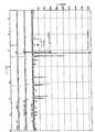
도 1은 실시예 1에서 얻어진 타겟의 X선 회절 차트를 나타낸 도면이다.1 is a diagram illustrating an X-ray diffraction chart of a target obtained in Example 1. FIG.
도 2는 실시예 2에서 얻어진 타겟의 X선 회절 차트를 나타낸 도면이다.FIG. 2 is a diagram showing an X-ray diffraction chart of a target obtained in Example 2. FIG.
<발명을 실시하기 위한 최량의 형태>BEST MODE FOR CARRYING OUT THE INVENTION [
이하, 본 발명을 상세히 설명한다.Hereinafter, the present invention will be described in detail.
I. 산화물 재료 및 스퍼터링 타겟I. Oxide Materials and Sputtering Targets
(I-1) 산화물 재료 및 스퍼터링 타겟의 구성(I-1) Structure of Oxide Material and Sputtering Target
본 발명의 스퍼터링 타겟은 본 발명의 소결체인 산화물 재료이기 때문에, 그의 구성은 동일하다. 따라서, 이하 이들을 모두 간단하게 스퍼터링 타겟 또는 타겟이라 하는 경우가 있다.Since the sputtering target of this invention is an oxide material which is a sintered compact of this invention, the structure is the same. Therefore, there are cases where these are all simply referred to as sputtering targets or targets.
본 발명의 타겟은 인듐, 주석, 금속 원소 M을 함유하고, 일메나이트 구조 화합물을 포함하는 것을 특징으로 한다.The target of the present invention is characterized by containing indium, tin and the metal element M, and containing a ilmenite structural compound.
금속 원소 M으로서는, +2가의 이온 반경이 1.1 Å 이하인 것이 바람직하고, 1.0 Å 이하인 것이 보다 바람직하다. 그와 같은 금속 원소로서는, Zn, Co, Mg, Mn, Ni 등을 들 수 있고, Zn인 것이 바람직하다.As metal element M, it is preferable that the +2 valence ion radius is 1.1 kPa or less, and it is more preferable that it is 1.0 kPa or less. As such a metal element, Zn, Co, Mg, Mn, Ni, etc. are mentioned, It is preferable that it is Zn.
일메나이트 구조란 결정 구조의 일종이며, 일반적으로 최밀 충전한 음이온(산화물로서는 산소 이온)에 의해 형성된 팔면체 간극의 2/3가 양이온에 의해 점유된 것을 말하고, 통상 ABO3으로 표시된다. 상세하게는 문헌 [「결정 화학 입문(아사쿠라 쇼뗀, 사사끼 요시노리ㆍ야마무라 히로시ㆍ가케가와 가즈유끼ㆍ야마무라 겐타로ㆍ이가라시 가오리 저)」]나 문헌 [「결정 화학 무기 재질 연구의 주발점(고단 사, 나카히라 미쯔오끼 저)] 등에 기재되어 있다.An ilmenite structure is a kind of crystal structure, and generally means that two-thirds of the octahedral gap formed by the closest-filled anion (oxygen ion as oxide) is occupied by a cation, and is usually represented by ABO3 . For details, refer to "Introduction to Crystal Chemistry (Shower Asakura, Yoshinori Sasaki, Hiroshi Yamamura, Kazuyuki Kazugawa, Gentaro Yamamura, Kaori Igarashi)", and "The main point of research on crystalline chemical weapon materials" Nakahira Mitsuoki).
타겟 중의 화합물의 결정 상태는 타겟으로부터 채취한 시료를 X선 회절법에 의해 관찰함으로써 판정할 수 있다.The crystal state of the compound in the target can be determined by observing a sample taken from the target by X-ray diffraction.
예를 들면, 주석 및 아연을 포함하는 일메나이트 구조 화합물(통상 ZnSnO3으로 표시됨)은 X선 회절에서 JCPDS(Joint Committee on Powder Diffraction Standards) 데이타베이스의 No.52-1381의 피크 패턴이나, 또는 유사한 (시프트된) 패턴을 나타내는 것을 말한다. In, Sn, Zn이 동일 사이트에 주기적으로 배치된 것에 더하여 랜덤하게 배치된 것도 포함된다(코랜덤이라 하는 경우도 있음).For example, a ilmenite structural compound (usually designated ZnSnO3 ) comprising tin and zinc is the peak pattern of No. 52-1381 in the Joint Committee on Powder Diffraction Standards (JCPDS) database, or similar in X-ray diffraction. Refers to a (shifted) pattern. In addition to those in which In, Sn, and Zn are periodically arranged at the same site, randomly arranged ones are also included (sometimes called "corandom").
본 발명의 타겟은, X선 회절(XRD)에 있어서의 일메나이트 구조 화합물의 최대 피크 강도가 루틸 구조 화합물의 6배 이상인 것이 바람직하다.As for the target of this invention, it is preferable that the maximum peak intensity of the monomenite structure compound in X-ray diffraction (XRD) is 6 times or more of a rutile structure compound.
일메나이트 구조 화합물의 최대 피크 강도가 루틸 구조 화합물의 최대 피크 강도의 6배보다 작으면, 타겟의 저항이 커지거나, 스퍼터링법으로 성막한 투명 도전막의 비저항 등의 물성의 면 내 변동이 커질 우려가 있다.If the maximum peak intensity of the ilmenite structure compound is less than six times the maximum peak intensity of the rutile structure compound, the resistance of the target may increase, or the in-plane variation of physical properties such as the specific resistance of the transparent conductive film formed by sputtering may increase. have.
일메나이트 구조 화합물의 최대 피크 강도가 루틸 구조 화합물의 최대 피크 강도의 6배 이상인 것은 X선 회절 차트를 해석함으로써 판정할 수 있다. 또한, 일메나이트 구조 화합물의 최대 피크 강도가 루틸 구조 화합물의 최대 피크 강도의 10배 이상이면 보다 바람직하다.It can be determined by analyzing the X-ray diffraction chart that the maximum peak intensity of the ilmenite structure compound is 6 times or more of the maximum peak intensity of the rutile structure compound. Moreover, it is more preferable if the maximum peak intensity of a ilmenite structure compound is 10 times or more of the maximum peak intensity of a rutile structure compound.
또한, 본 발명의 타겟에 있어서 일메나이트 구조 화합물 이외의 피크를 나타내는 화합물로서 생성이 예상되는 것은, Zn2SnO4로 표시되는 스피넬 구조 화합물, SnO2로 표시되는 루틸 구조 화합물, In2O3으로 표시되는 빅스바이트 구조 화합물, In2O3(ZnO)m으로 표시되는 육방정 층상 화합물, ZnO로 표시되는 우르짜이트 구조 화합물 등을 들 수 있다. 본 발명의 효과를 손상시키지 않는 범위 내에서 Sn2O로 표시되는 루틸 구조 화합물을 제외한 상기 구조물을 포함할 수 있지만, 일메나이트 구조 화합물과 빅스바이트 구조 화합물이 주성분인 것이 보다 바람직하고, 일메나이트 구조 화합물이 주성분인 것이 특히 바람직하다. 일메나이트 구조 화합물이 주성분인 것은 X선 회절 피크 강도로부터 판단할 수 있다.Further, as it is generated is estimated as ylmethoxy compound exhibiting a peak other than a nitro structural compound in the target of the present invention, Zn2 SnO4 spinel structural compound represented by the rutile structure, the compound represented by SnO2, In2 O3 represented Biggs byte structure compound, the hexagonal crystal lamellar compound represented byin 2 O 3 (ZnO) m , and the like Ur jjayi tree structure compound represented by the ZnO. Although it is possible to include the above-mentioned structure except the rutile structure compound represented by Sn2 O within the range that does not impair the effects of the present invention, it is more preferable that the ilmenite structure compound and the bixbite structure compound are the main component, and the ilmenite structure It is particularly preferred that the compound is the main component. It can be judged from the X-ray diffraction peak intensity that the ilmenite structural compound is the main component.
도 1은 실시예 1에서 제조된 타겟의 X선 회절 차트이다. 이 차트로부터, 실시예 1에서 제조된 타겟의 ZnSnO3으로 표시되는 일메나이트 구조 화합물의 최대 피크 강도가 SnO2로 표시되는 루틸 구조 화합물의 최대 피크 강도의 약 20배인 것, 일메나이트 구조 화합물이 주성분인 것을 알 수 있다.1 is an X-ray diffraction chart of a target prepared in Example 1. FIG. From this chart, the maximum peak intensity of the ilmenite structural compound represented by ZnSnO3 of the target prepared in Example 1 is about 20 times the maximum peak intensity of the rutile structural compound represented by SnO2 , wherein the ilmenite structural compound is the main component It can be seen that.
본 발명의 타겟은 In/(In+Sn+M)으로 표시되는 원자비가 0.25 내지 0.55의 범위 내, Sn/(In+Sn+M)으로 표시되는 원자비가 0.25 내지 0.5의 범위 내, M/(In+Sn+M)으로 표시되는 원자비가 0.2 내지 0.5의 범위 내인 것이 바람직하다.The target of the present invention has an atomic ratio of In / (In + Sn + M) in the range of 0.25 to 0.55, and an atomic ratio of Sn / (In + Sn + M) in the range of 0.25 to 0.5, M / ( It is preferable that the atomic ratio represented by In + Sn + M) falls within the range of 0.2 to 0.5.
여기서, 상기 각 원자비는 유도 결합 플라즈마(ICP) 발광 분석에 의해서 측정할 수 있다.Here, each atomic ratio can be measured by inductively coupled plasma (ICP) emission analysis.
In/(In+Sn+M)으로 표시되는 원자비는 0.25 미만이면, 다른 결정형을 갖는 화합물이 생성되어, 일메나이트 구조를 갖는 ZnSnO3 화합물의 생성이 곤란해지거나, 타겟의 저항이 높아질 우려가 있고, 0.55를 초과하면, 일메나이트 구조를 갖는 ZnSnO3 화합물의 생성이 곤란해지거나, 인듐 사용량이 너무 많아질 우려가 있다. In/(In+Sn+M)으로 표시되는 원자비는 0.25 내지 0.49 범위 내의 값인 것이 보다 바람직하고, 0.3 내지 0.45 범위 내의 값인 것이 더욱 바람직하다.If the atomic ratio represented by In / (In + Sn + M) is less than 0.25, a compound having a different crystalline form is produced, which makes it difficult to produce a ZnSnO3 compound having an ilmenite structure, or the resistance of the target is high. When the content exceeds 0.55, the production of a ZnSnO3 compound having a monomenite structure may be difficult or the amount of indium used may be too high. The atomic ratio represented by In / (In + Sn + M) is more preferably in the range of 0.25 to 0.49, still more preferably in the range of 0.3 to 0.45.
Sn/(In+Sn+M)으로 표시되는 원자비가 0.25 미만 또는 0.5를 초과하면, 일메나이트 구조를 갖는 ZnSnO3 화합물의 생성이 곤란해지거나, 타겟의 저항이 높아질 우려가 있다. Sn/(In+Sn+M)으로 표시되는 원자비는 0.3 내지 0.5 범위 내의 값인 것이 보다 바람직하고, 0.3 내지 0.45 범위 내의 값인 것이 더욱 바람직하고, 0.3 내지 0.4 범위 내의 값인 것이 특히 바람직하다.When the atomic ratio represented by Sn / (In + Sn + M) is less than 0.25 or more than 0.5, the production of ZnSnO3 compounds having a monomenite structure may be difficult or the resistance of the target may be increased. The atomic ratio represented by Sn / (In + Sn + M) is more preferably in the range of 0.3 to 0.5, still more preferably in the range of 0.3 to 0.45, and particularly preferably in the range of 0.3 to 0.4.
M/(In+Sn+M)으로 표시되는 원자비가 0.2 미만 또는 0.5를 초과하면, 일메나이트 구조를 갖는 MSn03 화합물의 생성이 곤란해질 우려가 있다. M/(In+Sn+M)으로 표시되는 원자비는 0.27 내지 0.45 범위 내의 값인 것이 보다 바람직하고, 0.3 내지 0.4 범위 내의 값인 것이 더욱 바람직하다.When the atomic ratio represented by M / (In + Sn + M) is less than 0.2 or more than 0.5, there is a possibility that the production of the MSn03 compound having a monomenite structure becomes difficult. It is more preferable that the atomic ratio represented by M / (In + Sn + M) is a value within the range of 0.27 to 0.45, and still more preferably a value within the range of 0.3 to 0.4.
본 발명의 타겟은, 일메나이트 구조 화합물의 X선 회절(XRD)에 있어서의 최대 피크 위치가 JCPDS 데이타베이스의 No.52-1381의 최대 피크 위치에서 마이너스 방향(협각측)으로 시프트되어 있는 것이 바람직하다.In the target of the present invention, it is preferable that the maximum peak position in X-ray diffraction (XRD) of the ilmenite structural compound is shifted in the negative direction (angle angle) from the maximum peak position of Nos. 52-1381 in the JCPDS database. Do.
피크 시프트의 각은 X선 회절 차트를 해석함으로써 측정할 수 있다. 도 1에 후술하는 실시예 1에서 얻어진 타겟의 X선 회절 차트를 나타낸다. 이 차트로부터, 일메나이트 구조 화합물의 최대 피크 위치가 마이너스 방향(협각측)으로 0.5도 시 프트되어 있는 것을 알 수 있다. 이것은, 인듐이 포함되어 있는 효과이며, ZnSnO3으로 추찰되는 일메나이트 구조 화합물의 격자간 거리가 넓어진 것으로 추정된다.The angle of the peak shift can be measured by analyzing an X-ray diffraction chart. The X-ray diffraction chart of the target obtained by Example 1 mentioned later in FIG. 1 is shown. From this chart, it can be seen that the maximum peak position of the ilmenite structural compound is shifted by 0.5 degrees in the negative direction (narrow angle side). This is an effect in which indium is contained, and it is estimated that the lattice distance of the ilmenite structure compound estimated by ZnSnO3 became wider.
시프트 폭이 작으면, 캐리어 발생이 불충분해져 타겟의 저항이 높아질 우려가 있다. 이것은, 일메나이트 구조 화합물 중에의 인듐의 고용량(원자수)이 불충분하여 캐리어 전자가 충분히 발생하지 않기 때문이라고 추찰된다. 또한, 시프트 폭이 작으면 인듐이 다른 결정 구조를 취하여, 타겟의 벌크 저항이 높아지거나 강도를 약하게 할 우려가 있다.If the shift width is small, there is a fear that carrier generation is insufficient and the resistance of the target is increased. It is inferred that this is because the high capacity (atomic number) of indium in the ilmenite structural compound is insufficient and carrier electrons are not sufficiently generated. In addition, if the shift width is small, indium may have a different crystal structure, and the bulk resistance of the target may be increased or the strength may be weakened.
일메나이트 구조 화합물의 최대 피크 위치는 마이너스(협각측) 방향으로 시프트되어 있는 것이 보다 바람직하고, 0.2도 이상 시프트되어 있는 것이 더욱 바람직하고, 0.3도 이상 시프트되어 있는 것이 특히 바람직하다.The maximum peak position of the monomenite structural compound is more preferably shifted in the negative (narrow angle) direction, more preferably 0.2 degrees or more, and particularly preferably 0.3 degrees or more.
본 발명의 타겟은 벌크 저항이 0.2 내지 10 mΩㆍcm의 범위 내인 산화물 소결체로 이루어지는 것이 바람직하다.It is preferable that the target of this invention consists of an oxide sintered compact whose bulk resistance exists in the range of 0.2-10 m (ohm) * cm.
타겟의 벌크 저항값의 측정은 사탐침법에 의해서 행할 수 있다.The measurement of the bulk resistance value of a target can be performed by the four probe method.
벌크 저항이 0.2 mΩㆍcm보다 작으면, 성막한 막보다 저항이 낮아지고, 비산된 막이 노듈의 원인이 될 우려가 있으며, 10 mΩㆍcm보다 크면, 안정한 스퍼터링을 행할 수 없을 우려가 있다.If the bulk resistance is smaller than 0.2 m? · Cm, the resistance is lower than that of the formed film, and the scattered film may cause the nodule. If the bulk resistance is larger than 10 m? · Cm, there is a possibility that stable sputtering may not be performed.
본 발명의 타겟의 벌크 저항은 0.3 내지 5 mΩㆍcm의 범위 내인 것이 보다 바람직하고, 0.4 내지 3 mΩㆍcm의 범위 내인 것이 더욱 바람직하다.The bulk resistance of the target of the present invention is more preferably in the range of 0.3 to 5 mΩ · cm, more preferably in the range of 0.4 to 3 mΩ · cm.
본 발명의 타겟은 이론 상대 밀도가 90 % 이상인 산화물 소결체인 것이 바 람직하다.The target of the present invention is preferably an oxide sintered body having a theoretical relative density of 90% or more.
타겟의 이론 상대 밀도가 90 %보다 작으면 방전 중에 타겟이 깨지는 원인이 될 우려가 있다.If the theoretical relative density of the target is less than 90%, the target may be broken during discharge.
본 발명의 타겟의 이론 상대 밀도는 90 % 이상인 것이 보다 바람직하고, 95 % 이상인 것이 더욱 바람직하고, 98 % 이상인 것이 특히 바람직하다.As for the theoretical relative density of the target of this invention, it is more preferable that it is 90% or more, It is still more preferable that it is 95% or more, It is especially preferable that it is 98% or more.
여기서, 타겟의 이론 상대 밀도는 다음과 같이 하여 구해진다.Here, the theoretical relative density of the target is obtained as follows.
ZnO, SnO2, In2O3의 비중을 각각 5.66 g/cm3, 6.95 g/cm3, 7.12 g/cm3으로 하여, 그의 양비로부터 밀도를 계산하고, 아르키메데스법으로 측정한 밀도와의 비율을 계산하여 이론 상대 밀도로 한다.The specific gravity of ZnO, SnO2 and In2 O3 is set to 5.66 g / cm3 , 6.95 g / cm3 and 7.12 g / cm3 , respectively, and the density is calculated from the amount ratio thereof, and the ratio with the density measured by the Archimedes method. Is calculated as the theoretical relative density.
본 발명의 타겟은 일메나이트 구조 화합물의 결정 입경이 20 μm 이하인 것이 바람직하다.It is preferable that the target particle of this invention is 20 micrometers or less in crystal grain diameter of a ilmenite structure compound.
일메나이트 구조 화합물의 결정 입경이 20 μm보다 크면, 입계가 응력 집중점이 되어 강도가 저하될 우려가 있다. 일메나이트 구조 화합물의 결정 입경은 8 μm 이하인 것이 보다 바람직하고, 4 μm 이하인 것이 특히 바람직하다.If the grain size of the ilmenite structural compound is larger than 20 µm, the grain boundary may become a stress concentration point and the strength may decrease. As for the crystal grain size of a ilmenite structure compound, it is more preferable that it is 8 micrometers or less, and it is especially preferable that it is 4 micrometers or less.
타겟 중의 일메나이트 구조 화합물의 결정 입경은 전자선 마이크로분석기(EPMA)에 의해서 측정할 수 있다.The grain size of the monomenite structural compound in the target can be measured by an electron beam microanalyzer (EPMA).
본 발명의 타겟의 저항력은 10 kg/mm2 이상인 것이 바람직하고, 11 kg/mm2 이상인 것이 보다 바람직하고, 12 kg/mm2 이상인 것이 특히 바람직하다. 타겟의 운 반, 부착시에 하중이 걸려 타겟이 파손될 우려가 있다는 이유로, 타겟에는 일정 이상의 저항력이 요구되고, 10 kg/mm2 미만이면, 타겟으로서의 사용에 견디지 못할 우려가 있다.It is preferable that the resistivity of the target of this invention is 10 kg / mm <2> or more, It is more preferable that it is 11 kg / mm <2> or more, It is especially preferable that it is 12 kg / mm <2> or more. Since the target may be damaged when the target is transported and attached, the target may require a certain resistance or more, and if the target is less than 10 kg / mm2 , it may not be able to withstand its use as a target.
타겟의 저항력은 JIS R 1601에 준하여 측정할 수 있다.The resistivity of a target can be measured according to JISR1601.
본 발명의 산화물 재료는 분체화할 수도 있고, 각종 투명 도전 재료에 응용 가능하다.The oxide material of the present invention may be powdered and applicable to various transparent conductive materials.
본 발명의 산화물 소결체를 분체화하는 방법으로서는, 볼 밀 등을 이용하여 분쇄하거나, 원료 분말을 성형하지 않고 소성시켜 소성 분말을 제조하는 것 등을 들 수 있다. 또한, 용액 중에서의 반응 등도 이용할 수 있다.As a method of powdering the oxide sintered compact of this invention, it is grind | pulverized using a ball mill etc., or it calcined without shape | molding raw material powder, etc. are mentioned. Moreover, reaction in a solution, etc. can also be used.
분체화한 본 발명의 산화물 소결체(투명 도전성 산화물 분말)의 용도로서는, 도전막이나 유전막용 도포 재료의 원료 등을 들 수 있다.Examples of the use of the powdered oxide sintered body (transparent conductive oxide powder) of the present invention include raw materials of conductive films and coating materials for dielectric films.
(I-2) 타겟의 제조 방법(I-2) Manufacturing Method of Target
본 발명의 스퍼터링 타겟(일메나이트 구조 화합물을 포함하는 산화물 재료)의 제조 방법(이하, 본 발명의 타겟 제조 방법이라 하는 경우가 있음)은 주석 화합물, 원소 M의 화합물, 인듐 화합물을 원료로 하고, 원료 총량 중의 인듐 원자비(In/(In+Sn+M))가 0.25 내지 0.55이고, 주석 원자비 (Sn/(In+Sn+M))가 0.25 내지 0.5이고, 또한 700 ℃ 이상의 온도에서 열 처리하는 공정을 포함하는 것을 특징으로 한다.The method for producing the sputtering target (an oxide material containing a ilmenite structure compound) of the present invention (hereinafter sometimes referred to as the target production method of the present invention) uses a tin compound, a compound of the element M, and an indium compound as raw materials, Indium atomic ratio (In / (In + Sn + M)) in the total amount of the raw materials is 0.25 to 0.55, tin atomic ratio (Sn / (In + Sn + M)) is 0.25 to 0.5, and is heated at a temperature of 700 DEG C or higher. It characterized by including the process of processing.
종래, 700 ℃를 초과하는 온도 조건하에서는, 일메나이트 구조 화합물을 생 성시키는 것이 곤란하지만, 상기 본 발명의 타겟 제조 방법에 따르면, 열 안정성이 있는 주석을 포함하는 일메나이트 구조 화합물을 생성시킬 수 있다.Conventionally, it is difficult to produce ilmenite structural compounds under temperature conditions exceeding 700 ° C., but according to the target production method of the present invention, ilmenite structural compounds containing tin having thermal stability can be produced. .
이하, 본 발명의 일메나이트 구조 화합물을 포함하는 산화물 재료로 이루어지는 타겟 제조 방법을 공정마다 설명한다.Hereinafter, the target manufacturing method which consists of an oxide material containing the ilmenite structural compound of this invention is demonstrated for every process.
(1) 배합 공정(1) compounding process
배합 공정은 스퍼터링 타겟의 원료인 금속 화합물을 혼합하는 공정이다.A compounding process is a process of mixing the metal compound which is a raw material of a sputtering target.
타겟의 제조 원료에 사용되는 각 금속 화합물은 통상적인 혼합 분쇄기, 예를 들면 습식 볼 밀이나 비드 밀, 또는 초음파 장치를 이용하여 균일하게 혼합ㆍ분쇄하는 것이 바람직하다.It is preferable to mix and grind | pulverize each metal compound used for the manufacturing raw material of a target uniformly using a conventional mixing grinder, for example, a wet ball mill, a bead mill, or an ultrasonic apparatus.
타겟의 원료인 인듐, 아연, 금속 원소 M의 화합물은 In/(In+Sn+M)으로 표시되는 원자비가 0.25 내지 0.55 범위 내인 것이 필요하고, 바람직하게는 Sn/(In+Sn+M)으로 표시되는 원자비가 0.25 내지 0.5의 범위 내, M/(In+Sn+M)으로 표시되는 원자비가 0.2 내지 0.5의 범위 내로 배합한다. In/(In+Sn+M)으로 표시되는 원자비가 상기 범위를 벗어나면, 상기 효과를 갖는 본 발명의 타겟은 얻어지지 않는다.The compound of indium, zinc and metal element M, which is a raw material of the target, needs to have an atomic ratio represented by In / (In + Sn + M) in the range of 0.25 to 0.55, and preferably Sn / (In + Sn + M). The atomic ratio shown is mix | blended in the range of 0.25-0.5, and the atomic ratio represented by M / (In + Sn + M) is 0.2 to 0.5. If the atomic ratio represented by In / (In + Sn + M) is out of the above range, the target of the present invention having the above effect is not obtained.
또한, Sn/(Sn+M)으로 표시되는 원자비는 0.3 내지 0.45의 범위 내인 것이 보다 바람직하고, 0.3 내지 0.40의 범위 내인 것이 특히 바람직하다. 상기 범위 내이면, ZnSnO3 화합물을 생성하기 쉽다. 특히 Sn/(Sn+M)이 0.5보다 크면 SnO2가 생성되어 타겟의 저항이 높아질 우려가 있다.In addition, the atomic ratio represented by Sn / (Sn + M) is more preferably in the range of 0.3 to 0.45, and particularly preferably in the range of 0.3 to 0.40. Is within the above range, it is easy to create a ZnSnO3 compound. In particular, when Sn / (Sn + M) is larger than 0.5, SnO2 is generated, which may increase the resistance of the target.
인듐 화합물로서는, 예를 들면 산화인듐, 수산화인듐 등을 들 수 있다.As an indium compound, indium oxide, indium hydroxide, etc. are mentioned, for example.
주석 화합물로서는, 예를 들면 산화주석, 수산화주석 등을 들 수 있다.As a tin compound, tin oxide, tin hydroxide, etc. are mentioned, for example.
금속 원소 M으로서는 아연이 바람직하고, 아연 화합물로서는, 예를 들면 산화아연, 수산화아연 등을 들 수 있다.Zinc is preferable as the metal element M, and zinc oxide, zinc hydroxide, etc. are mentioned as a zinc compound, for example.
각각의 화합물로서, 소결 용이성, 부생성물 잔존의 어려움으로 인해 산화물이 바람직하다.As the respective compounds, oxides are preferred due to the ease of sintering and the difficulty of remaining byproducts.
각 원료의 순도는 통상 2 N(99 질량%) 이상, 바람직하게는 3 N(99.9 질량%) 이상, 보다 바람직하게는 4 N(99.99 질량%) 이상이다. 순도가 2 N보다 낮으면, 일메나이트 구조를 갖는 ZnSnO3 화합물이 생성되기 어려워지거나 타겟에 변색 등의 불량이 발생할 우려가 있다.The purity of each raw material is usually 2 N (99 mass%) or more, preferably 3 N (99.9 mass%) or more, and more preferably 4 N (99.99 mass%) or more. If the purity is lower than 2 N, the ZnSnO3 compound having a monomenite structure may be less likely to be produced or defects such as discoloration may occur in the target.
타겟의 제조 원료인 금속 산화물을 분쇄하는 경우, 분쇄 후의 금속 산화물의 입경은 통상 10 μm 이하, 바람직하게는 3 μm 이하로 하는 것이 바람직하다. 금속 산화물의 입경이 너무 크면, 타겟의 밀도가 높아지기 어려워질 우려가 있다.When pulverizing the metal oxide which is a raw material for producing the target, the particle diameter of the pulverized metal oxide is usually 10 μm or less, preferably 3 μm or less. If the particle size of the metal oxide is too large, there is a fear that the density of the target becomes difficult.
타겟의 원료가 되는 금속 화합물의 분쇄 후의 입경은 JIS R 1619에 준하여 측정할 수 있다.The particle diameter after grinding of the metal compound used as a raw material of a target can be measured according to JISR1619.
(2) 예비 소결 공정(2) pre-sintering process
예비 소결 공정은 인듐 화합물, 주석 화합물 및 금속 원소 M의 화합물(바람직하게는 아연 화합물)의 혼합물을 얻은 후, 이 혼합물을 예비 소결(열 처리)하는, 필요에 따라서 설치되는 공정이다.Preliminary sintering process is a process provided as needed, after obtaining the mixture of an indium compound, a tin compound, and the compound of the metal element M (preferably zinc compound), and preliminarily sintering this mixture (heat processing).
예비 소결 공정에서는, 상기 혼합물을 500 내지 1,200 ℃에서 1 내지 100 시간의 조건에서 열 처리하는 것이 바람직하다.In the pre-sintering step, the mixture is preferably heat treated at 500 to 1,200 ° C. under conditions of 1 to 100 hours.
이 이유는, 500 ℃ 미만 또는 1 시간 미만의 열 처리 조건에서는, 인듐 화합물이나 금속 원소 M의 화합물(바람직하게는 아연 화합물), 주석 화합물의 열 분해가 불충분해지는 경우가 있기 때문이다. 한편, 열 처리 조건이 1,200 ℃를 초과한 경우 또는 100 시간을 초과한 경우에는, 입자의 조대화가 발생하는 경우가 있기 때문이다.This is because, under heat treatment conditions of less than 500 ° C or less than 1 hour, thermal decomposition of the indium compound, the compound of the metal element M (preferably zinc compound), and the tin compound may be insufficient. On the other hand, when the heat treatment conditions exceed 1,200 degreeC or when it exceeds 100 hours, coarsening of a particle may generate | occur | produce.
따라서, 특히 바람직한 것은 800 내지 1,200 ℃의 온도 범위에서 2 내지 50 시간의 조건에서 열 처리(예비 소결)하는 것이다.Therefore, particularly preferred is heat treatment (pre sintering) at a condition of 2 to 50 hours in the temperature range of 800 to 1,200 ° C.
또한, 여기서 얻어진 예비 소결물은 성형하여 소결하기 전에 분쇄하는 것이 바람직하다. 이 예비 소결물의 분쇄는 볼 밀, 롤 밀, 펄 밀, 제트 밀 등을 이용하여 입경이 0.01 내지 1.0 μm가 되도록 하는 것이 좋다.In addition, it is preferable to grind | pulverize the pre-sintered thing obtained here before shape | molding and sintering. The preliminary sintered product may be pulverized to have a particle diameter of 0.01 to 1.0 µm using a ball mill, roll mill, pearl mill, jet mill, or the like.
예비 소결물의 입경은 JIS R 1619에 준하여 측정할 수 있다.The particle size of the presintered product can be measured according to JIS R 1619.
(3) 성형 공정(3) forming process
성형 공정은 금속 산화물의 혼합물(상기 예비 소결 공정을 설치한 경우에는 예비 소결물)을 가압 성형하여 성형체로 하는 필수적인 공정이다. 성형 공정에 있어서, 얻어진 예비 소결물을 이용하여 타겟으로서 바람직한 형상으로 성형한다. 예비 소결 공정을 설치한 경우에는 얻어진 예비 소결물의 미분말을 조립한 후, 프레스 성형에 의해 원하는 형상으로 성형할 수 있다.The molding step is an essential step of forming a molded body by pressing and molding a mixture of metal oxides (preliminary sintered product in the case where the preliminary sintering step is provided). In the shaping | molding process, it shape | molds in a shape suitable as a target using the obtained presintered material. In the case of providing a preliminary sintering step, the fine powder obtained can be granulated and then molded into a desired shape by press molding.
본 발명에서 사용할 수 있는 성형 처리로서는, 금형 성형, 캐스팅 성형, 사 출 성형 등을 들 수 있지만, 소결 밀도가 높은 소결체를 얻기 위해서는, 냉간 정수압(CIP) 등으로 성형한 후, 후술하는 소결 처리하는 것이 바람직하다.Examples of the molding treatment which can be used in the present invention include mold molding, casting molding, injection molding, and the like. However, in order to obtain a sintered compact having a high sintered density, after molding by cold hydrostatic pressure (CIP) or the like, the sintering treatment described later is performed. It is preferable.
또한, 성형 처리에 있어서는, 폴리비닐알코올이나 메틸셀룰로오스, 폴리왁스, 올레산 등의 성형 보조제를 이용할 수도 있다.Moreover, in shaping | molding process, shaping | molding adjuvant, such as polyvinyl alcohol, methylcellulose, polywax, and oleic acid, can also be used.
(4) 소성 공정(4) firing process
소결 공정은 상기 성형 공정에서 얻어진 미분말을 조립한 후, 프레스 성형에 의해 원하는 형상으로 성형한 성형체를, 700 ℃ 이상의 온도에서 소성(열 처리)시키는 필수적인 공정이다.The sintering step is an essential step of assembling the fine powder obtained in the above molding step, and then firing (heat treatment) the molded article formed into a desired shape by press molding at a temperature of 700 ° C or higher.
소성은 열간 정수압(HIP) 소성 등에 의해서 행할 수 있다.Firing can be performed by hot hydrostatic pressure (HIP) firing or the like.
이 경우의 소성 조건은 통상 산소 가스 분위기 또는 산소 가스 가압하에 700 내지 1,700 ℃, 바람직하게는 1,100 내지 1,600 ℃, 더욱 바람직하게는 1,300 내지 1,500 ℃에서 30 분 내지 360 시간, 바람직하게는 8 내지 180 시간, 보다 바람직하게는 12 내지 96 시간이다.The firing conditions in this case are usually 30 minutes to 360 hours, preferably 8 to 180 hours at 700 to 1,700 ° C, preferably 1,100 to 1,600 ° C, more preferably 1,300 to 1,500 ° C, under oxygen gas atmosphere or oxygen gas pressurization. More preferably, it is 12 to 96 hours.
한편, 분말 혼합물을 산소 가스를 함유하지 않는 분위기에서 소성시키거나, 1,700 ℃ 이상의 온도에서 소성시키면, 육방정 층상 화합물이 우선하여, 일메나이트 구조 화합물의 형성이 충분하지 않게 되는 경우가 있다. 또한, 700 ℃보다 낮으면 목적으로 하는 결정형이 생성되지 않고 타겟의 소결 밀도가 높아지지 않아 타겟의 저항이 올라가거나 강도가 저하될 우려가 있다. 또한, 소결 온도가 낮으면 저항이 높은 In2O3(ZnO)m(m은 4 내지 20의 정수)이 발생할 우려가 있다.On the other hand, when the powder mixture is calcined in an atmosphere containing no oxygen gas, or calcined at a temperature of 1,700 ° C. or more, the hexagonal layered compound may preferentially form the formation of the ilmenite structure compound in some cases. If the temperature is lower than 700 ° C, the target crystal form is not produced and the sintered density of the target does not increase, so that the resistance of the target may increase or the strength may decrease. In addition, when the sintering temperature is low, In2 O3 (ZnO)m having high resistance (m is an integer of 4 to 20) may be generated.
소성시의 승온 속도는 통상 5 내지 600 ℃/시간의 범위 내, 바람직하게는 50 내지 500 ℃/시간의 범위 내, 보다 바람직하게는 100 내지 400 ℃/시간의 범위 내이다. 600 ℃/시간보다 빠르면 육방정 층상 화합물이 생성되고, 일메나이트 구조 화합물의 형성이 충분하지 않게 되는 경우가 있다. 5 ℃/시간보다 느리면 시간이 너무 소요되어 생산성이 저하될 우려가 있다.The temperature increase rate at the time of baking is normally in the range of 5-600 degreeC / hour, Preferably it is in the range of 50-500 degreeC / hour, More preferably, it is in the range of 100-400 degreeC / hour. If it is faster than 600 DEG C / hour, a hexagonal layered compound is produced, and the formation of the ilmenite structure compound may not be sufficient. If it is slower than 5 DEG C / hour, it takes too much time and there is a fear that productivity is lowered.
또한, 강온 속도는 통상 5 내지 600 ℃/시간의 범위 내, 바람직하게는 50 내지 500 ℃/시간의 범위 내, 보다 바람직하게는 100 내지 400 ℃/시간의 범위 내이다. 600 ℃/시간보다 빠르면 육방정 층상 화합물이 생성되고, 일메나이트 구조 화합물의 형성이 충분하지 않게 되는 경우가 있다. 5 ℃/시간보다 느리면 시간이 너무 소요되어 생산성이 저하될 우려가 있다.In addition, the temperature-fall rate is usually in the range of 5 to 600 ° C / hour, preferably in the range of 50 to 500 ° C / hour, more preferably in the range of 100 to 400 ° C / hour. If it is faster than 600 DEG C / hour, a hexagonal layered compound is produced, and the formation of the ilmenite structure compound may not be sufficient. If it is slower than 5 DEG C / hour, it takes too much time and there is a fear that productivity is lowered.
(5) 환원 공정(5) reduction process
환원 공정은, 상기 소성 공정에서 얻어진 소결체의 벌크 저항을 타겟 전체로서 균일화하기 위해서 환원 처리를 행하는, 필요에 따라서 설치되는 공정이다.A reduction process is a process provided as needed to perform a reduction process in order to make the bulk resistance of the sintered compact obtained by the said baking process uniform as a whole target.
본 공정에서 적용할 수 있는 환원 방법으로서는, 예를 들면 환원성 가스에 의한 방법이나 진공 소성 또는 불활성 가스에 의한 환원 등을 들 수 있다.As a reduction method which can be applied in this process, the method by a reducing gas, the vacuum baking, or the reduction by an inert gas etc. are mentioned, for example.
환원성 가스에 의한 경우, 수소, 메탄, 일산화탄소나, 이들 가스와 산소와의 혼합 가스 등을 사용할 수 있다.In the case of a reducing gas, hydrogen, methane, carbon monoxide, a mixed gas of these gases and oxygen, or the like can be used.
또한, 불활성 가스 중에서의 소성에 의한 환원의 경우, 질소, 아르곤이나, 이들 가스와 산소와의 혼합 가스 등을 사용할 수 있다.In the case of reduction by firing in an inert gas, nitrogen, argon, a mixed gas of these gases and oxygen, or the like can be used.
환원 온도는 통상 100 내지 800 ℃의 범위 내, 바람직하게는 200 내지 800 ℃의 범위 내이다. 또한, 환원 시간은 통상 0.01 내지 10 시간의 범위 내, 바람직하게는 0.05 내지 5 시간의 범위 내이다.The reduction temperature is usually in the range of 100 to 800 ° C, preferably in the range of 200 to 800 ° C. The reduction time is usually in the range of 0.01 to 10 hours, preferably in the range of 0.05 to 5 hours.
(6) 가공 공정(6) machining process
가공 공정은, 상기와 같이 하여 소결하여 얻어진 소결체를 또한 스퍼터링 장치에의 장착에 적합한 형상으로 절삭 가공하고, 배킹 플레이트 등의 장착용 치구를 부착하기 위한, 필요에 따라서 설치되는 공정이다.A processing process is a process provided as needed for cutting and processing the sintered compact obtained by sintering as mentioned above to the shape suitable for attachment to a sputtering apparatus, and attaching mounting fixtures, such as a backing plate.
타겟의 두께는 통상 2 내지 20 mm의 범위 내, 바람직하게는 3 내지 12 mm의 범위 내, 특히 바람직하게는 4 내지 6 mm의 범위 내이다. 또한, 복수개의 타겟을 하나의 배킹 플레이트에 부착시켜 실질적으로 하나의 타겟으로 할 수도 있다. 또한, 표면은 80 내지 10,000번의 다이아몬드 지석에 의해 마무리를 행하는 것이 바람직하고, 100 내지 1000번의 다이아몬드 지석에 의해 마무리를 행하는 것이 특히 바람직하다. 80번보다 작은 다이아몬드 지석을 사용하면 타겟이 깨지기 쉬워질 우려가 있다.The thickness of the target is usually in the range of 2 to 20 mm, preferably in the range of 3 to 12 mm, particularly preferably in the range of 4 to 6 mm. In addition, a plurality of targets may be attached to one backing plate to be substantially one target. In addition, the surface is preferably finished with 80 to 10,000 diamond grindstones, and particularly preferably 100 to 1000 diamond grindstones. If you use a diamond grindstone smaller than 80, the target may be easily broken.
본 발명의 타겟을 제조하기 위해서는, 상기 본 발명의 타겟 제조 방법을 이용하는 것이 바람직하지만, 타겟의 원료인 인듐, 주석 및 금속 원소 M의 화합물을 상기 특정 원자비로 혼합하여, 상기 소성 공정에서의 소성 온도 조건(열 처리 조건)을 이용하기만 하면, 그 이외의 공정에 대해서는 특별히 한정되지 않고, 예를 들면 일본 특허 공개 제2002-69544호 공보, 일본 특허 공개 제2004-359984호 공보, 일본 특허 제3628554호 등에 개시되어 있는 공지된 방법도 이용할 수도 있다.In order to manufacture the target of this invention, it is preferable to use the target manufacturing method of this invention, However, The compound of indium, tin, and metal element M which are raw materials of a target is mixed by the said specific atomic ratio, and it bakes in the said baking process As long as temperature conditions (heat treatment conditions) are used, other processes are not particularly limited. For example, Japanese Patent Application Laid-Open No. 2002-69544, Japanese Patent Application Laid-Open No. 2004-359984, and Japanese Patent Application The known method disclosed in 3628554 etc. can also be used.
또한, 실제 공업용 스퍼터링 타겟의 제조 방법으로서, 다음과 같은 방법을 채용할 수도 있다. 또한, 이들 방법의 일부를 조합한 제조 방법을 이용할 수도 있다.In addition, as a manufacturing method of an actual industrial sputtering target, the following method can also be employ | adopted. Moreover, the manufacturing method which combined some of these methods can also be used.
공업용 스퍼터링 타겟의 제조 방법(1)Manufacturing method of industrial sputtering target (1)
(i) 칭량된 원료를 물, 보조제와 함께 볼 밀ㆍ비드 밀 등에서 습식 혼합ㆍ분쇄한다.(i) The weighed raw materials are wet-mixed and pulverized in a ball mill, bead mill, etc. together with water and auxiliary agents.
(ii) 얻어진 원료 혼합물을 분무 드라이어 등으로 건조ㆍ조립(造粒)하여 조립 분말을 만든다.(ii) The obtained raw material mixture is dried and granulated with a spray dryer or the like to form granulated powder.
(iii) 얻어진 조립 분말을 프레스 성형한 후, 고무형에서 SIP 성형한다.(iii) The obtained granulated powder is press molded and then SIP molded in a rubber mold.
(iv) 얻어진 성형체를 산소 가압하에 소성시켜 소성체를 얻는다.(iv) The obtained molded body is baked under oxygen pressure to obtain a fired body.
(v) 얻어진 소성체를 다이아몬드 커터ㆍ워터 커터 등으로 절삭 후, 다이아몬드 지석 등으로 연마한다.(v) The resulting fired body is cut with a diamond cutter or water cutter, and then polished with a diamond grindstone or the like.
(vi) 이타르인듐 등 왁스제를 도포하여 구리 등으로 제조한 배킹 플레이트와 접합시킨다.(vi) Waxing agents, such as itarium, are apply | coated and it joins with the backing plate made from copper etc.
(vii) 왁스제 처리, 산화층 제거 등을 위한 배킹 플레이트 연마, 타겟 표면 처리를 행한다.(vii) Backing plate polishing and target surface treatment for wax treatment, oxide layer removal and the like are performed.
공업용 스퍼터링 타겟의 제조 방법(2)Manufacturing method of industrial sputtering target (2)
(i) 칭량된 원료를 볼 밀 등으로 건식 혼합ㆍ분쇄하여 조립 분말을 만든다.(i) Dry weighing and grinding of the weighed raw materials with a ball mill or the like to form granulated powder.
(ii) 얻어진 조립 분말을 프레스 성형한다.(ii) The obtained granulated powder is press molded.
(iii) 얻어진 성형체를 대기압에서 소성시켜 소성체를 얻는다.(iii) The obtained molded body is baked at atmospheric pressure to obtain a fired body.
공업용 스퍼터링 타겟의 제조 방법(3)Manufacturing method of industrial sputtering target (3)
(i) 칭량된 원료를 볼 밀 등으로 건식 혼합ㆍ분쇄하여 조립 분말을 만든다.(i) Dry weighing and grinding of the weighed raw materials with a ball mill or the like to form granulated powder.
(ii) 얻어진 조립 분말을 볼 밀ㆍV 블렌더 등으로 습식 혼합ㆍ분쇄하여 조립 분산액을 얻는다.(ii) The obtained granulated powder is wet mixed and pulverized with a ball mill, V blender or the like to obtain a granulated dispersion.
(iii) 얻어진 조립 분산액으로부터 캐스팅 성형으로 성형체를 얻는다.(iii) A molded product is obtained by casting molding from the obtained granulated dispersion.
(iv) 얻어진 성형체를 지지체 상에서 공기에 접촉시켜 건조시킨 후, 대기압에서 소성시켜 소성체를 얻는다.(iv) The obtained molded body is brought into contact with air on a support and dried, and then fired at atmospheric pressure to obtain a fired body.
II. 투명 도전막II. Transparent conductive film
(II-1) 투명 도전막의 구성(II-1) Structure of Transparent Conductive Film
본 발명의 투명 도전막은 상기 본 발명의 스퍼터링 타겟을 스퍼터링법에 의해 성막하여 이루어지는 것을 특징으로 한다.The transparent conductive film of the present invention is formed by forming a sputtering target of the present invention by a sputtering method.
본 발명의 투명 도전막은 비정질 또는 미세 결정의 것이 바람직하고, 비정질의 것이 특히 바람직하다. 결정성이면, 후술하는 투명 전극 제조시의 에칭 속도가 늦어지거나 에칭 후에 잔여물이 남거나 할 우려가 있다.The transparent conductive film of the present invention is preferably amorphous or fine crystal, and particularly preferably amorphous. If it is crystallinity, there exists a possibility that the etching speed at the time of manufacture of the transparent electrode mentioned later may become slow, or a residue may remain after an etching.
본 발명의 투명 도전막은 금속 배선 에칭액인 PAN(인산, 아세트산, 질산의 혼합산)에 대한 내성을 갖는 것이 바람직하다. 투명 도전막이 PAN 내성을 가지면, 투명 도전막 상에 금속 배선을 성막한 후, 투명 도전막을 용해시키지 않고 금속 배선의 에칭을 행할 수 있다.It is preferable that the transparent conductive film of this invention has tolerance to PAN (mixed acid of phosphoric acid, acetic acid, and nitric acid) which is a metal wiring etching liquid. If a transparent conductive film has PAN resistance, after forming metal wiring on a transparent conductive film, metal wiring can be etched without melt | dissolving a transparent conductive film.
본 발명의 투명 도전막은 그의 비저항이 1800 μΩㆍcm 이하인 것이 바람직하고, 1300 μΩㆍcm 이하인 것이 보다 바람직하고, 900 μΩㆍcm 이하인 것이 특히 바람직하다.It is preferable that the specific resistance of the transparent conductive film of this invention is 1800 microohm * cm or less, It is more preferable that it is 1300 microohm * cm or less, It is especially preferable that it is 900 microohm * cm or less.
투명 도전막의 비저항은 사탐침법에 의해 측정할 수 있다.The specific resistance of a transparent conductive film can be measured by the four probe method.
본 발명의 투명 도전막에 있어서는, 비저항의 면 내 분포(Max/Min)가 0 내지 10의 범위 내인 것이 바람직하다.In the transparent conductive film of this invention, it is preferable that the in-plane distribution (Max / Min) of specific resistance exists in the range of 0-10.
여기서, 비저항의 면 내 분포(Max/Min)란, 사탐침법으로 6 내지 100점 측정한 비저항 중 최대의 것을 최소의 것으로 나눈 값으로 정의된다.Here, the in-plane distribution (Max / Min) of the specific resistance is defined as a value obtained by dividing the largest one among the specific resistances measured from 6 to 100 points by the probe probe method.
비저항의 면 내 분포(Max/Min)가 10을 초과하면, 투명 도전막을 전극으로 한 경우에, 부분적으로 동작 불량을 일으키거나 불량률이 높아질 우려가 있다. 비저항의 면 내 분포(Max/Min)는 0 내지 5의 범위 내인 것이 보다 바람직하고, 0 내지 2의 범위 내인 것이 특히 바람직하다.When the in-plane distribution (Max / Min) of specific resistance exceeds 10, when a transparent conductive film is used as an electrode, there exists a possibility that it may cause a malfunction or a defect rate may become high partially. The in-plane distribution (Max / Min) of the specific resistance is more preferably in the range of 0 to 5, and particularly preferably in the range of 0 to 2.
본 발명의 투명 도전막의 막 두께는 통상 1 내지 500 nm의 범위 내, 바람직하게는 10 내지 240 nm의 범위 내, 보다 바람직하게는 20 내지 190 nm의 범위 내이다.The film thickness of the transparent conductive film of this invention is usually in the range of 1-500 nm, Preferably it is in the range of 10-240 nm, More preferably, it is in the range of 20-190 nm.
투명 도전막의 막 두께는 촉침법에 의해서 측정할 수 있다.The film thickness of a transparent conductive film can be measured by the styling method.
본 발명의 투명 도전막은 TFT 구동 액정 패널의 컬러 필터측에 설치되어, 투명 공통 전극으로서 사용할 수 있다.The transparent conductive film of this invention is provided in the color filter side of a TFT drive liquid crystal panel, and can be used as a transparent common electrode.
여기서, 투명 공통 전극이란, TFT 구동 액정 패널의 컬러 필터측의 투명 전극을 말한다. 투명 공통 전극으로서 필요한 특성은 투과율이 85 % 이상, 비저항이 2000 μΩㆍcm 이하이고, 본 발명의 투명 전극은 이들 특성을 구비하는 것이다.Here, a transparent common electrode means the transparent electrode of the color filter side of a TFT drive liquid crystal panel. As a characteristic required as a transparent common electrode, a transmittance | permeability is 85% or more and specific resistance is 2000 microohm * cm or less, and the transparent electrode of this invention is equipped with these characteristics.
또한, 본 발명의 투명 도전막은 대기하에서의 열 안정성이 우수하고, 내구성이 높은 전극으로서 사용할 수 있다.Moreover, the transparent conductive film of this invention is excellent in thermal stability in air | atmosphere, and can be used as an electrode with high durability.
(II-2) 투명 도전막의 제조 방법(II-2) Manufacturing Method of Transparent Conductive Film
본 발명의 투명 도전막을 제조하기 위한 스퍼터링법 및 스퍼터링 조건에 특별히 제한은 없지만, 직류(DC) 마그네트론법, 교류(AC) 마그네트론법, 고주파(RF) 마그네트론법이 바람직하다. 액정(LCD) 패널 용도에서는 장치가 대형화되기 때문에, DC 마그네트론법, AC 마그네트론법이 바람직하고, 안정한 성막이 가능한 AC 마그네트론법이 특히 바람직하다.Although there is no restriction | limiting in particular in the sputtering method and sputtering conditions for manufacturing the transparent conductive film of this invention, The direct current (DC) magnetron method, the alternating current (AC) magnetron method, and the high frequency (RF) magnetron method are preferable. In a liquid crystal (LCD) panel use, since the apparatus becomes large, the DC magnetron method and the AC magnetron method are preferable, and the AC magnetron method which can stably form a film is especially preferable.
스퍼터 조건으로서는, 스퍼터 압력이 통상 0.05 내지 2 Pa의 범위 내, 바람직하게는 0.1 내지 1 Pa의 범위 내, 보다 바람직하게는 0.2 내지 0.8 Pa의 범위 내, 도달 압력이 통상 10-3 내지 10-7 Pa의 범위 내, 바람직하게는 5×10⁻⁴ 내지 10-6 Pa의 범위 내, 보다 바람직하게는 10-4내지 10-5 Pa의 범위 내, 기판 온도가 통상 25 내지 500 ℃의 범위 내, 바람직하게는 50 내지 300 ℃의 범위 내, 보다 바람직하게는 100 내지 250 ℃의 범위 내이다.As the sputtering conditions, the sputter pressure is usually in the range of 0.05 to 2 Pa, preferably in the range of 0.1 to 1 Pa, more preferably in the range of 0.2 to 0.8 Pa, and the attained pressure is usually 10-3 to 10-7 Within the range of Pa, preferably within the range of 5 × 10⁻⁴ to 10−6 Pa, more preferably within the range of 10−4 to 10−5 Pa, and the substrate temperature is usually within the range of 25 to 500 ° C., Preferably it is in the range of 50-300 degreeC, More preferably, it is in the range of 100-250 degreeC.
도입 가스로서, 통상 Ne, Ar, Kr, Xe 등의 불활성 가스를 사용할 수 있지만, 이들 중 성막 속도가 빠른 점에서 Ar(아르곤)이 바람직하다. 또한, Zn/Sn<1의 경우, 도입 가스가 산소를 0.01 내지 5 % 포함하면, 타겟의 벌크 저항이 낮아지기 쉬워 바람직하다. Zn/Sn>2의 경우, 도입 가스가 수소를 0.01 내지 5 % 포함하면, 얻어지는 투명 도전막의 저항이 낮아지기 쉬워 바람직하다.As the introduction gas, inert gases such as Ne, Ar, Kr, and Xe can usually be used, but among them, Ar (argon) is preferable because of the high film formation speed. In the case of Zn / Sn <1, when the introduction gas contains 0.01 to 5% of oxygen, the bulk resistance of the target tends to be low, which is preferable. In the case of Zn / Sn> 2, when the introduction gas contains 0.01 to 5% of hydrogen, the resistance of the obtained transparent conductive film tends to be low, which is preferable.
III. 투명 전극III. Transparent electrode
(III-1) 투명 전극의 구성(III-1) Structure of Transparent Electrode
본 발명의 투명 전극은 상기 본 발명의 투명 도전막을 건식 에칭하여 제조된 것을 특징으로 한다. 따라서, 본 발명의 투명 전극은 상기 본 발명의 투명 도전막의 상기 특성을 구비하고 있다.The transparent electrode of the present invention is produced by dry etching the transparent conductive film of the present invention. Therefore, the transparent electrode of the present invention has the above characteristics of the transparent conductive film of the present invention.
본 발명의 투명 전극은 전극 단부의 테이퍼 각이 60 내지 120도의 범위 내인 것이 바람직하다. 전극 단부의 테이퍼 각은 단면을 전자 현미경(SEM)에 의해 관찰함으로써 측정할 수 있다.It is preferable that the taper angle of an electrode edge part of the transparent electrode of this invention exists in the range of 60-120 degree. The taper angle of an electrode end can be measured by observing a cross section with an electron microscope (SEM).
전극 단부의 테이퍼 각이 60도보다 작으면 전극 엣지 부분의 거리가 길어져, 액정 패널이나 유기 EL 패널을 구동시킨 경우, 화소 주변부와 내부에서 콘트라스트에 차가 생기는 경우가 있다. 또한, 120도를 초과하면 엣지 부분의 전극 균열이나 박리가 발생하여 배향막의 불량이나 단선의 원인이 될 우려가 있다.If the taper angle of the electrode end is smaller than 60 degrees, the distance of the electrode edge portion becomes long, and when the liquid crystal panel or the organic EL panel is driven, there may be a difference in contrast between the pixel peripheral portion and the inside. Moreover, when it exceeds 120 degree | times, an electrode crack and peeling of an edge part generate | occur | produce, and there exists a possibility that it may become the cause of the defect or disconnection of an orientation film.
(III-2) 투명 전극의 제조 방법(III-2) Manufacturing Method of Transparent Electrode
본 발명의 투명 전극의 제조 방법은 상기 본 발명의 투명 도전막을 건식 에칭하는 것을 특징으로 한다. 건식 에칭법을 이용함으로써, 선폭이 가는 패턴이 높은 정밀도로 얻어진다고 하는 이점이 있다.The manufacturing method of the transparent electrode of this invention is characterized by dry-etching the transparent conductive film of the said this invention. By using the dry etching method, there is an advantage that a pattern having a thin line width is obtained with high accuracy.
본 발명의 투명 전극을 제조하기 위한 건식 에칭 방법에는 특별히 제한은 없고, 목적, 상황에 따라서 적합한 에칭 조건을 선택할 수 있지만, 바람직하게는 하기와 같다.There is no restriction | limiting in particular in the dry etching method for manufacturing the transparent electrode of this invention, Although suitable etching conditions can be selected according to the objective and the situation, Preferably it is as follows.
비특허 문헌 5 등에 기재된 방법을 이용할 수 있다. 그 중에서도 반응성 이온 에칭이 테이퍼 각을 조정하기 쉬워 바람직하다.The method described in the nonpatent literature 5 etc. can be used. Especially, reactive ion etching is preferable because it is easy to adjust a taper angle.
이하, 실시예를 들어 본 발명을 더욱 구체적으로 설명하지만, 본 발명이 실시예로 한정되는 것은 아니다.Hereinafter, although an Example is given and this invention is demonstrated further more concretely, this invention is not limited to an Example.
실시예 1Example 1
(1) 스퍼터링 타겟의 제조(1) Production of sputtering target
원료로서, 평균 입경이 3.4 μm, 순도 4 N의 산화인듐, 0.6 μm, 순도 4 N의 산화아연, 0.5 μm, 순도 4 N의 산화주석을, 원자비[In/(In+Sn+Zn)]가 0.36, 원자비[Sn/(In+Sn+Zn)]가 0.33, 원자비[Zn/(In+Sn+Zn)]가 0.31이 되도록 혼합하여 이것을 습식 볼 밀에 공급하고, 72 시간 혼합 분쇄하여 원료 미세 분말을 얻었다.As a raw material, an average particle diameter of 3.4 μm, indium oxide having a purity of 4 N, 0.6 μm, zinc oxide having a purity of 4 N, 0.5 μm, and tin oxide having a purity of 4 N was used as an atomic ratio [In / (In + Sn + Zn)]. Is 0.36, atomic ratio [Sn / (In + Sn + Zn)] is 0.33, atomic ratio [Zn / (In + Sn + Zn)] is mixed so that 0.31 is supplied to the wet ball mill, and mixed and pulverized for 72 hours. To obtain a raw fine powder.
얻어진 원료 미세 분말을 조립한 후, 직경 10 cm, 두께 5 mm의 치수로 프레스 성형하고, 이것을 소성로에 넣고, 산소 가스압하에 1,400 ℃에서 48 시간의 조건에서 소성시켜 소결체(타겟)를 얻었다. 승온 속도는 100 ℃/시간이었다.After the obtained raw material fine powder was granulated, it was press-molded in the dimension of diameter 10cm and thickness 5mm, it was put into the baking furnace, and it baked under the conditions of 48 hours at 1,400 degreeC under oxygen gas pressure, and obtained the sintered compact (target). The temperature increase rate was 100 degreeC / hour.
(2) 스퍼터링 타겟의 평가(2) Evaluation of Sputtering Target
얻어진 타겟에 대하여 이론 상대 밀도, 벌크 저항값, X선 회절 분석, 결정 입경 및 각종 물성을 측정하였다. 도 1에 실시예 1에서 얻어진 타겟의 X선 회절 차트를 나타낸다.The theoretical target density, bulk resistance value, X-ray diffraction analysis, grain size, and various physical properties of the obtained target were measured. 1 shows the X-ray diffraction chart of the target obtained in Example 1. FIG.
그 결과, 이론 상대 밀도는 98 %이고, 사탐침법에 의해 측정한 벌크 저항값은 1.0 mΩㆍcm였다. 또한, 제조한 타겟의 저항력을 측정한 결과, 14 kg/mm2였다. 저항력의 측정은 JIS R 1601에 준하여 행하였다.As a result, the theoretical relative density was 98%, and the bulk resistance value measured by the four probe method was 1.0 mΩ · cm. Moreover, it was 14 kg / mm <2> when the resistivity of the produced target was measured. The resistance was measured in accordance with JIS R 1601.
또한, 이 소결체로부터 채취한 시료에 대하여, X선 회절법에 의해 투명 도전 재료(타겟) 중의 결정 상태를 관찰한 결과, 얻어진 타겟 중에는, 주로 ZnSnO3으로 표시되는 일메나이트 구조 화합물이 확인되었다. SnO2로 표시되는 루틸 구조 화합물도 약간 확인되었지만, 그 밖의 화합물에 대해서는 확인되지 않았다. 또한, 일메나이트 구조 화합물을 나타내는 피크는 마이너스 방향(협각측)으로 시프트되어 있고, 최대 피크의 시프트 폭은 약 0.5도였다.Further, while with respect to a sample collected from this sintered body, a result of observing the crystalline state of the transparent conductive material (the target) by an X-ray diffraction method, the obtained target, were identified Ilmenite structure compound primarily represented by ZnSnO3. The rutile structure compound represented by SnO2 was also slightly confirmed, but was not confirmed for other compounds. In addition, the peak which shows the ilmenite structural compound was shifted in the negative direction (narrow angle side), and the shift width of the largest peak was about 0.5 degree.
ZnSnO3로 표시되는 일메나이트 구조 화합물이란, X선 회절에서 JCPDS 데이타베이스의 No.52-1381의 피크 패턴이나, 또는 유사한 (시프트된) 패턴을 나타내는 것을 말한다.The ilmenite structural compound represented by ZnSnO3 refers to a peak pattern of Nos. 52-1381 of the JCPDS database or a similar (shifted) pattern in X-ray diffraction.
또한, 얻어진 소결체를 수지에 매립하고, 그 표면을 입경 0.05 μm의 알루미나 입자로 연마한 후, 전자선 마이크로분석기(EPMA)인 JXA-8621MX(닛본 덴시사 제조)에 의해 5,000배로 확대한 소결체 표면의 30 μm×30 μm 사방의 테두리 내에서 관찰되는 결정 입자의 최대 직경을 측정하였다. 3 개소의 테두리 내에서 동일하게 측정한 각각의 최대 입경의 평균값을 산출하고, 이 소결체의 결정 입경이 3.0 μm인 것을 확인하였다.Further, the obtained sintered body was embedded in a resin, and the surface thereof was polished with alumina particles having a particle diameter of 0.05 μm, and then 30 times the surface of the sintered body enlarged 5,000 times by JXA-8621MX (manufactured by Nippon Denshi Co., Ltd.) which is an electron beam microanalyzer (EPMA). The maximum diameter of the crystal grains observed within the rim of 占 퐉 占 30 占 퐉 was measured. The average value of each largest particle diameter measured similarly in three edges was computed, and it confirmed that the crystal grain diameter of this sintered compact was 3.0 micrometers.
또한, (1)에서 얻어진 소결체를 절삭 가공하여 직경 약 10 cm, 두께 약 5 mm의 스퍼터링 타겟을 제조하고, 이것을 이용하여 스퍼터링법에 의해 투명 도전막의 제조를 행하였다.Furthermore, the sintered compact obtained by (1) was cut and the sputtering target of about 10 cm in diameter and about 5 mm in thickness was manufactured, and the transparent conductive film was manufactured by the sputtering method using this.
(3) 투명 도전성 산화물(투명 도전막)의 성막(3) Formation of Transparent Conductive Oxide (Transparent Conductive Film)
상기 (1)에서 얻어진 스퍼터링 타겟을 DC 마그네트론 스퍼터링 장치에 장착 하고, 실온에서 유리 기판 상에 투명 도전막을 성막하였다.The sputtering target obtained in said (1) was attached to the DC magnetron sputtering apparatus, and the transparent conductive film was formed into a film on the glass substrate at room temperature.
여기서의 스퍼터 조건으로서는, 스퍼터 압력 1×10⁻¹ Pa, 도달 압력 5×10⁻⁴ Pa, 기판 온도 200 ℃, 투입 전력 120 W, 성막 시간 15 분간으로 하였다.As sputter | spatter conditions here, it was set as sputter | spatter
이 결과, 유리 기판 상에, 막 두께가 약 100 nm인 투명 도전성 산화물이 형성된 투명 도전 유리가 얻어졌다.As a result, a transparent conductive glass on which a transparent conductive oxide having a film thickness of about 100 nm was formed on a glass substrate.
또한, 막 두께 분포가 평균화되도록 기판 폴더를 회전시킨 후에, 기판 폴더의 반경상 6점의 비저항을 측정하고, 그의 최대값을 최소값으로 나누어 비저항의 면 내 분포를 평가한 결과 1.1로 면 내 분포가 매우 작았다.After the substrate folder was rotated so that the film thickness distribution was averaged, the resistivity of the six points in the radius of the substrate folder was measured, and the in-plane distribution of the specific resistance was evaluated by dividing its maximum value by the minimum value. Very small.
또한, 표 1에 있어서 PAN 내성 평가의 표시는 50 ℃, 20 nm/분 이하를 「○」로 나타내고, 50 ℃, 20 nm/분을 초과하는 경우를 「×」로 나타낸다.In addition, in Table 1, the indication of PAN tolerance evaluation shows 50 degreeC and 20 nm / min or less as "(circle)", and shows the case where it exceeds 50 degreeC and 20 nm / min by "x".
(4) 스퍼터 상태의 평가(4) Evaluation of Sputter State
(i) 이상 방전의 발생수(i) Number of occurrences of abnormal discharge
(1)에서 얻어진 스퍼터링 타겟을 DC 마그네트론 스퍼터링 장치에 장착하고, 아르곤 가스에 3 %의 수소 가스를 첨가한 혼합 가스를 이용한 것 외에는, 상기 (3)과 동일한 조건하에서 240 시간 연속하여 스퍼터링을 행하여 이상 방전의 유무를 모니터링하였지만 한 번도 확인되지 않았다. 표 1에 있어서 이상 방전 유무의 표시는 이상 방전 없음의 경우를 「○」로 나타내고, 이상 방전 있음의 경우를 「×」로 나타낸다.The sputtering target obtained in (1) was mounted on a DC magnetron sputtering apparatus, and sputtering was performed continuously for 240 hours under the same conditions as in (3), except that a mixed gas in which 3% hydrogen gas was added to argon gas was used. The presence or absence of the discharge was monitored but never confirmed. In Table 1, the display of the presence or absence of abnormal discharge shows the case of no abnormal discharge as "(circle)" and the case of abnormal discharge as "x".
(ii) 노듈 발생수(ii) number of nodule generation
상기 (i)과 동일한 조건에서 8 시간 연속하여 스퍼터링을 행하였다. 이어서, 스퍼터링 후의 타겟의 표면을 실체 현미경에 의해 30배로 확대하여 관찰하였다. 타겟 상의 3점에서 시야 900 mm2중에서의 20 μm 이상의 노듈 발생수를 각각 측정하고, 평균화한 값을 표 1에 나타내었다.Sputtering was performed continuously for 8 hours under the same conditions as the above (i). Next, the surface of the target after sputtering was magnified and observed 30 times with a stereomicroscope. Table 1 shows the average number of nodule occurrences of 20 µm or more in the 900 mm2 field of view at three points on the target, and averages the results.
(5) 투명 도전막의 물성 평가(5) Evaluation of Physical Properties of Transparent Conductive Film
상기 (3)에서 얻어진 투명 도전 유리 상의 투명 도전막의 도전성에 대하여 사탐침법에 의해 비저항을 측정한 결과, 750 μΩㆍcm였다.The resistivity of the transparent conductive film on the transparent conductive glass obtained in the above (3) was measured by a four probe method, and the result was 750 µΩ · cm.
또한, 이 투명 도전막은 X선 회절 분석에 의해 비정질인 것을 확인하였다. 한편, 막 표면의 평활성에 대해서도, P-V값(JISB0601 준거)이 5 nm인 것으로부터 양호한 것을 확인하였다.In addition, the transparent conductive film was confirmed to be amorphous by X-ray diffraction analysis. On the other hand, also about the smoothness of the film surface, it confirmed that it was favorable from P-V value (JISB0601 conformity) being 5 nm.
또한, 이 투명 도전막의 투명성에 대해서는, 분광 광도계에 의해 파장 500 nm의 광선에 대한 광선 투과율이 91 %이고, 투명성에 있어서도 우수한 것이었다.Moreover, about the transparency of this transparent conductive film, the light transmittance with respect to the light of wavelength 500nm was 91% with the spectrophotometer, and it was excellent also in transparency.
또한, X선 회절 측정(XRD)의 측정 조건은 이하와 같았다.In addition, the measurement conditions of X-ray-diffraction measurement (XRD) were as follows.
장치: (주)리가쿠 제조 Ultima-IIIDevice: Ultima-III manufactured by Rigaku Corporation
X선: Cu-Kα선(파장 1.5406 Å, 흑연 모노크로미터로써 단색화)X-ray: Cu-Kα (wavelength: 1.5406 단색화, monochrome as graphite monochromator)
2θ-θ 반사법, 연속 스캔(1.0 °/분)2θ-θ reflection, continuous scan (1.0 ° / min)
샘플링 간격: 0.02°Sampling interval: 0.02 °
슬릿 DS, SS: 2/3°, RS: 0.6 mmSlit DS, SS: 2/3 °, RS: 0.6 mm
실시예 2 및 비교예 1 내지 5Example 2 and Comparative Examples 1 to 5
원료 조성비를 표 1에 나타내는 원자비가 되도록 조정하고, 비교예 3 내지 5는 RF 마그네트론 스퍼터링을 이용한 것 외에는 실시예 1과 동일하게 타겟 및 투명 도전막을 제조하여 평가하였다. 결과를 표 1에 나타낸다. 또한, 도 2에 실시예 2에서 얻어진 타겟의 X선 회절 차트를 나타낸다.The raw material composition ratio was adjusted to the atomic ratio shown in Table 1, and Comparative Examples 3 to 5 were prepared and evaluated in the same manner as in Example 1 except that RF magnetron sputtering was used. The results are shown in Table 1. In addition, the X-ray diffraction chart of the target obtained in Example 2 is shown in FIG.

표 1의 결과로부터, 실시예와 비교예를 비교하면, 일메나이트 구조 화합물을 포함하는 실시예 1은 인듐 함유량이 동일한 비교예 1 내지 3의 결정형에 비해 타겟의 저항이 낮으며 소결 밀도가 높은 것을 알 수 있었다. 또한, 스퍼터링시에 노듈의 발생도 없고, 성막된 투명 도전막의 비저항의 면 내 분포도 작은 것을 알 수 있었다.From the results of Table 1, comparing Example and Comparative Example, Example 1 containing a ilmenite structure compound has a lower resistance and higher sintered density of the target than the crystalline forms of Comparative Examples 1 to 3 having the same indium content. Could know. Moreover, it turned out that no nodule generate | occur | produces at the time of sputtering, and the in-plane distribution of the specific resistance of the formed transparent conductive film was also small.
또한, 주석, 아연의 비가 동일한 비교예 4, 5와 비교하면, 실시예만이 일메나이트 구조 화합물을 함유하는 것을 알 수 있다.In addition, it can be seen that only the examples contain ilmenite structural compounds when compared with the comparative examples 4 and 5 in which the ratios of tin and zinc are the same.
실시예 3Example 3
실시예 1과 동일힌 조성으로 본 발명의 대형 타겟을 제조하고, 로드록 장착 대형 스퍼터 장치에 의해 투명 도전막을 제막하여 액정 패널의 투명 공통 전극을 제조하였다. 액정 패널은 문제없이 구동하고, ITO를 이용하여 제조한 것과 손색없는 것을 확인할 수 있었다.The large target of this invention was manufactured with the composition similar to Example 1, the transparent conductive film was formed into a film by the load lock mounting large sputter apparatus, and the transparent common electrode of the liquid crystal panel was produced. The liquid crystal panel was driven without problems, and it was confirmed that it was comparable to that produced using ITO.
본 발명에 따르면, 가스 센서, 온도 센서, 태양 전지 전극에 이용 가능한 일메나이트 구조 화합물 함유 재료 및 그의 제조 방법을 제공할 수 있다. 또한, 그것을 이용한, 이론 상대 밀도가 높고, 저항이 낮으며 강도가 높고, 인듐 함유량이 적고, 스퍼터링법을 이용하여 투명 도전막을 성막할 때 발생하는 이상 방전을 억제하여 안정적으로 스퍼터링을 행할 수 있는 타겟, 이들의 타겟을 이용하여 제조한 비저항의 면 내 분포가 작은 투명 도전막을 제공할 수 있다.According to the present invention, it is possible to provide a ilmenite structure compound-containing material and a manufacturing method thereof that can be used for a gas sensor, a temperature sensor, and a solar cell electrode. In addition, a target having high theoretical relative density, low resistance, high strength, low indium content, low indium content, and abnormal sputtering generated when a transparent conductive film is formed by the sputtering method can be used for stable sputtering. And the transparent conductive film with small in-plane distribution of specific resistance manufactured using these target can be provided.
본 발명의 투명 도전막은 도전성, 면 내 균일성, 내열성 등이 우수하고, 액정 디스플레이로 대표되는 디스플레이나 터치 패널, 상변화형 광 기록 매체의 유전체 보호층 등 각종 용도에 유용하다.The transparent conductive film of the present invention is excellent in conductivity, in-plane uniformity, heat resistance, and the like, and is useful for various applications such as a display, a touch panel represented by a liquid crystal display, and a dielectric protective layer of a phase change type optical recording medium.
본 발명의 투명 도전막은 TFT 구동 액정 패널의 컬러 필터측에 투명 공통 전 극으로서 특히 유용하다.The transparent conductive film of the present invention is particularly useful as a transparent common electrode on the color filter side of a TFT drive liquid crystal panel.
또한, 본 발명의 타겟은 안정적으로 스퍼터링을 행할 수 있기 때문에, 성막 조건을 조정하거나 하여 TFT(박막 트랜지스터)로 대표되는 투명 산화물 반도체의 성막에도 적용할 수 있다.In addition, since the target of the present invention can be stably sputtered, the present invention can be applied to film formation of a transparent oxide semiconductor represented by a TFT (thin film transistor) by adjusting the film formation conditions.
Claims (13)
Translated fromKoreanApplications Claiming Priority (2)
| Application Number | Priority Date | Filing Date | Title |
|---|---|---|---|
| JP2005276813 | 2005-09-22 | ||
| JPJP-P-2005-00276813 | 2005-09-22 |
Publications (2)
| Publication Number | Publication Date |
|---|---|
| KR20080058346A KR20080058346A (en) | 2008-06-25 |
| KR101211747B1true KR101211747B1 (en) | 2012-12-12 |
Family
ID=37888794
Family Applications (1)
| Application Number | Title | Priority Date | Filing Date |
|---|---|---|---|
| KR1020087006862AExpired - Fee RelatedKR101211747B1 (en) | 2005-09-22 | 2006-09-15 | Oxide material and sputtering target |
Country Status (6)
| Country | Link |
|---|---|
| US (1) | US8637124B2 (en) |
| JP (1) | JP4960244B2 (en) |
| KR (1) | KR101211747B1 (en) |
| CN (1) | CN101268026B (en) |
| TW (1) | TWI401234B (en) |
| WO (1) | WO2007034749A1 (en) |
Families Citing this family (24)
| Publication number | Priority date | Publication date | Assignee | Title |
|---|---|---|---|---|
| US8304359B2 (en)* | 2005-09-27 | 2012-11-06 | Idemitsu Kosan Co., Ltd. | Sputtering target, transparent conductive film, and transparent electrode for touch panel |
| JP4994068B2 (en)* | 2006-08-09 | 2012-08-08 | 出光興産株式会社 | Oxide conductive material and manufacturing method thereof |
| JP5145513B2 (en)* | 2008-12-12 | 2013-02-20 | 出光興産株式会社 | Composite oxide sintered body and sputtering target comprising the same |
| JP5724157B2 (en)* | 2009-04-13 | 2015-05-27 | 日立金属株式会社 | Oxide semiconductor target and method of manufacturing oxide semiconductor device using the same |
| KR20120091026A (en)* | 2009-09-30 | 2012-08-17 | 이데미쓰 고산 가부시키가이샤 | Sintered in-ga-zn-o-type oxide |
| JP2012124446A (en) | 2010-04-07 | 2012-06-28 | Kobe Steel Ltd | Oxide for semiconductor layer of thin film transistor and sputtering target, and thin film transistor |
| JP2012033854A (en) | 2010-04-20 | 2012-02-16 | Kobe Steel Ltd | Oxide for semiconductor layer of thin film transistor, sputtering target, and thin film transistor |
| JP5718072B2 (en) | 2010-07-30 | 2015-05-13 | 三星ディスプレイ株式會社Samsung Display Co.,Ltd. | Thin film transistor oxide for semiconductor layer and sputtering target, and thin film transistor |
| JP5651095B2 (en)* | 2010-11-16 | 2015-01-07 | 株式会社コベルコ科研 | Oxide sintered body and sputtering target |
| JP2013070010A (en)* | 2010-11-26 | 2013-04-18 | Kobe Steel Ltd | Semiconductor layer oxide and spattering target for thin film transistor, and thin film transistor |
| JP2012164963A (en)* | 2010-11-26 | 2012-08-30 | Kobe Steel Ltd | Oxide for semiconductor layer of thin-film transistor and sputtering target, and thin-film transistor |
| JP5750063B2 (en)* | 2011-02-10 | 2015-07-15 | 株式会社コベルコ科研 | Oxide sintered body and sputtering target |
| JP2012180248A (en)* | 2011-03-02 | 2012-09-20 | Kobelco Kaken:Kk | Sintered oxide and sputtering target |
| JP2012180247A (en)* | 2011-03-02 | 2012-09-20 | Kobelco Kaken:Kk | Sintered oxide and sputtering target |
| TW201343940A (en)* | 2012-03-14 | 2013-11-01 | Corning Inc | Sputtering targets and associated sputtering methods for forming hermetic barrier layers |
| WO2013179676A1 (en) | 2012-05-31 | 2013-12-05 | 出光興産株式会社 | Sputtering target |
| JP6284710B2 (en)* | 2012-10-18 | 2018-02-28 | 出光興産株式会社 | Sputtering target, oxide semiconductor thin film, and manufacturing method thereof |
| US10017849B2 (en) | 2012-11-29 | 2018-07-10 | Corning Incorporated | High rate deposition systems and processes for forming hermetic barrier layers |
| CN103819177B (en)* | 2013-12-11 | 2015-09-09 | 广西晶联光电材料有限责任公司 | A kind of preparation method of ITiO target material |
| JP6159867B1 (en)* | 2016-12-22 | 2017-07-05 | Jx金属株式会社 | Transparent conductive film forming target, transparent conductive film forming target manufacturing method, and transparent conductive film manufacturing method |
| CN108709915B (en)* | 2018-09-01 | 2021-11-19 | 山东多瑞电子科技有限公司 | Harmful gas detection device in car |
| JP7456992B2 (en)* | 2019-02-18 | 2024-03-27 | 出光興産株式会社 | Oxide sintered body, sputtering target, and method for producing sputtering target |
| CN113423860A (en)* | 2019-02-18 | 2021-09-21 | 出光兴产株式会社 | Oxide sintered body, sputtering target, and method for producing sputtering target |
| CN109813741B (en)* | 2019-04-03 | 2021-11-19 | 广西壮族自治区冶金产品质量检验站 | Method for carrying out phase analysis on tin-doped indium oxide powder by adopting X-ray diffraction method |
Citations (1)
| Publication number | Priority date | Publication date | Assignee | Title |
|---|---|---|---|---|
| JP2000256061A (en) | 1999-03-05 | 2000-09-19 | Idemitsu Kosan Co Ltd | Transparent conductive material, transparent conductive glass and transparent conductive film |
Family Cites Families (13)
| Publication number | Priority date | Publication date | Assignee | Title |
|---|---|---|---|---|
| US4716086A (en)* | 1984-12-19 | 1987-12-29 | Ppg Industries, Inc. | Protective overcoat for low emissivity coated article |
| JPH0570943A (en)* | 1991-09-11 | 1993-03-23 | Mitsubishi Materials Corp | High density sintered target material for forming electric conductive transparent thin film by sputtering |
| JP2695605B2 (en) | 1992-12-15 | 1998-01-14 | 出光興産株式会社 | Target and manufacturing method thereof |
| CA2150724A1 (en) | 1992-12-15 | 1994-06-23 | Akira Kaijou | Transparent electrically conductive layer, electrically conductive transparent substrate and electrically conductive material |
| JPH06318406A (en)* | 1992-12-16 | 1994-11-15 | Idemitsu Kosan Co Ltd | Conductive transparent base member and manufacture thereof |
| JP4221532B2 (en)* | 1998-06-26 | 2009-02-12 | 三菱瓦斯化学株式会社 | Methylamine production catalyst and method for producing methylamines using the catalyst |
| KR100622168B1 (en) | 1998-08-31 | 2006-09-07 | 이데미쓰 고산 가부시키가이샤 | Targets for transparent conductive films, transparent conductive materials, transparent conductive glass and transparent conductive films |
| DE60041353D1 (en)* | 1999-11-25 | 2009-02-26 | Idemitsu Kosan Co | SPUTTERTARGET, TRANSPARENT CONDUCTIVE OXID AND PREPARATION PROCESS FOR SPUTTERTARGET |
| DE19957827C2 (en) | 1999-11-25 | 2003-06-12 | Epigenomics Ag | Use of an oligomer array with PNA and / or DNA oligomers on a surface |
| JP3961172B2 (en)* | 1999-11-26 | 2007-08-22 | アルプス電気株式会社 | Oxide transparent conductive film, oxide transparent conductive film forming target, substrate manufacturing method, electronic apparatus, and liquid crystal display device provided with previous oxide transparent conductive film |
| US6590227B2 (en)* | 1999-12-27 | 2003-07-08 | Semiconductor Energy Laboratory Co., Ltd. | Active matrix display device |
| KR101002492B1 (en) | 2002-08-02 | 2010-12-17 | 이데미쓰 고산 가부시키가이샤 | Sputtering target, sintered compact, conductive film manufactured using these, organic EL element, and board | substrate used for this |
| WO2005063628A1 (en) | 2003-12-25 | 2005-07-14 | Mitsui Mining & Smelting Co., Ltd. | Indium oxide-tin oxide powder and sputtering target using the same |
- 2006
- 2006-09-15KRKR1020087006862Apatent/KR101211747B1/ennot_activeExpired - Fee Related
- 2006-09-15USUS12/067,705patent/US8637124B2/enactiveActive
- 2006-09-15CNCN2006800348329Apatent/CN101268026B/ennot_activeExpired - Fee Related
- 2006-09-15JPJP2007536471Apatent/JP4960244B2/enactiveActive
- 2006-09-15WOPCT/JP2006/318391patent/WO2007034749A1/enactiveApplication Filing
- 2006-09-20TWTW095134820Apatent/TWI401234B/ennot_activeIP Right Cessation
Patent Citations (1)
| Publication number | Priority date | Publication date | Assignee | Title |
|---|---|---|---|---|
| JP2000256061A (en) | 1999-03-05 | 2000-09-19 | Idemitsu Kosan Co Ltd | Transparent conductive material, transparent conductive glass and transparent conductive film |
Also Published As
| Publication number | Publication date |
|---|---|
| TWI401234B (en) | 2013-07-11 |
| KR20080058346A (en) | 2008-06-25 |
| US20100266787A1 (en) | 2010-10-21 |
| TW200724516A (en) | 2007-07-01 |
| CN101268026B (en) | 2013-07-03 |
| CN101268026A (en) | 2008-09-17 |
| JP4960244B2 (en) | 2012-06-27 |
| WO2007034749A1 (en) | 2007-03-29 |
| JPWO2007034749A1 (en) | 2009-03-26 |
| US8637124B2 (en) | 2014-01-28 |
Similar Documents
| Publication | Publication Date | Title |
|---|---|---|
| KR101211747B1 (en) | Oxide material and sputtering target | |
| KR101080527B1 (en) | Sputtering target, transparent conductive film and transparent electrode | |
| TWI400346B (en) | Sputtering target, transparent conductive film and touch panel with transparent electrode | |
| JP4850378B2 (en) | Sputtering target, transparent conductive oxide, and method for producing sputtering target | |
| KR100306565B1 (en) | Transparent conductive film and manufacturing method thereof, conductive transparent film with transparent conductive film, conductive transparent glass, and conductive material | |
| KR101244092B1 (en) | Transparent conductive film, transparent electrode, and electrode base plate and manufacturing method of the same | |
| JP4933756B2 (en) | Sputtering target | |
| WO2010018707A1 (en) | Gallium oxide-tin oxide based oxide sintered body and oxide film | |
| CN103518003A (en) | In2O3-ZnO Sputtering Target | |
| EP1905864B1 (en) | In Sm OXIDE SPUTTERING TARGET | |
| JP2010070418A (en) | SnO2-In2O3-BASED OXIDE SINTERED COMPACT AND AMORPHOUS TRANSPARENT CONDUCTIVE FILM | |
| JP4947942B2 (en) | Sputtering target | |
| KR20070096017A (en) | SnO₂-based sputtering target and its manufacturing method | |
| JP2012148937A (en) | Electrically conductive composite oxide, zinc oxide type sintered body, method for manufacturing it and target | |
| JP2012126619A (en) | Zinc oxide sintered compact and method for producing the same | |
| JP2012031521A (en) | Sputtering target and transparent conductive film |
Legal Events
| Date | Code | Title | Description |
|---|---|---|---|
| PA0105 | International application | St.27 status event code:A-0-1-A10-A15-nap-PA0105 | |
| PG1501 | Laying open of application | St.27 status event code:A-1-1-Q10-Q12-nap-PG1501 | |
| A201 | Request for examination | ||
| P11-X000 | Amendment of application requested | St.27 status event code:A-2-2-P10-P11-nap-X000 | |
| P13-X000 | Application amended | St.27 status event code:A-2-2-P10-P13-nap-X000 | |
| PA0201 | Request for examination | St.27 status event code:A-1-2-D10-D11-exm-PA0201 | |
| E701 | Decision to grant or registration of patent right | ||
| PE0701 | Decision of registration | St.27 status event code:A-1-2-D10-D22-exm-PE0701 | |
| GRNT | Written decision to grant | ||
| PR0701 | Registration of establishment | St.27 status event code:A-2-4-F10-F11-exm-PR0701 | |
| PR1002 | Payment of registration fee | St.27 status event code:A-2-2-U10-U12-oth-PR1002 Fee payment year number:1 | |
| PG1601 | Publication of registration | St.27 status event code:A-4-4-Q10-Q13-nap-PG1601 | |
| FPAY | Annual fee payment | Payment date:20151118 Year of fee payment:4 | |
| PR1001 | Payment of annual fee | St.27 status event code:A-4-4-U10-U11-oth-PR1001 Fee payment year number:4 | |
| FPAY | Annual fee payment | Payment date:20161123 Year of fee payment:5 | |
| PR1001 | Payment of annual fee | St.27 status event code:A-4-4-U10-U11-oth-PR1001 Fee payment year number:5 | |
| FPAY | Annual fee payment | Payment date:20171114 Year of fee payment:6 | |
| PR1001 | Payment of annual fee | St.27 status event code:A-4-4-U10-U11-oth-PR1001 Fee payment year number:6 | |
| FPAY | Annual fee payment | Payment date:20181121 Year of fee payment:7 | |
| PR1001 | Payment of annual fee | St.27 status event code:A-4-4-U10-U11-oth-PR1001 Fee payment year number:7 | |
| FPAY | Annual fee payment | Payment date:20191120 Year of fee payment:8 | |
| PR1001 | Payment of annual fee | St.27 status event code:A-4-4-U10-U11-oth-PR1001 Fee payment year number:8 | |
| PR1001 | Payment of annual fee | St.27 status event code:A-4-4-U10-U11-oth-PR1001 Fee payment year number:9 | |
| R18-X000 | Changes to party contact information recorded | St.27 status event code:A-5-5-R10-R18-oth-X000 | |
| PR1001 | Payment of annual fee | St.27 status event code:A-4-4-U10-U11-oth-PR1001 Fee payment year number:10 | |
| PR1001 | Payment of annual fee | St.27 status event code:A-4-4-U10-U11-oth-PR1001 Fee payment year number:11 | |
| PR1001 | Payment of annual fee | St.27 status event code:A-4-4-U10-U11-oth-PR1001 Fee payment year number:12 | |
| PC1903 | Unpaid annual fee | St.27 status event code:A-4-4-U10-U13-oth-PC1903 Not in force date:20241207 Payment event data comment text:Termination Category : DEFAULT_OF_REGISTRATION_FEE | |
| PC1903 | Unpaid annual fee | St.27 status event code:N-4-6-H10-H13-oth-PC1903 Ip right cessation event data comment text:Termination Category : DEFAULT_OF_REGISTRATION_FEE Not in force date:20241207 |