KR101210645B1 - Led lighting system - Google Patents
Led lighting systemDownload PDFInfo
- Publication number
- KR101210645B1 KR101210645B1KR1020100121153AKR20100121153AKR101210645B1KR 101210645 B1KR101210645 B1KR 101210645B1KR 1020100121153 AKR1020100121153 AKR 1020100121153AKR 20100121153 AKR20100121153 AKR 20100121153AKR 101210645 B1KR101210645 B1KR 101210645B1
- Authority
- KR
- South Korea
- Prior art keywords
- power
- converter
- led
- lighting
- unit
- Prior art date
- Legal status (The legal status is an assumption and is not a legal conclusion. Google has not performed a legal analysis and makes no representation as to the accuracy of the status listed.)
- Expired - Fee Related
Links
Images


Classifications
- F—MECHANICAL ENGINEERING; LIGHTING; HEATING; WEAPONS; BLASTING
- F21—LIGHTING
- F21K—NON-ELECTRIC LIGHT SOURCES USING LUMINESCENCE; LIGHT SOURCES USING ELECTROCHEMILUMINESCENCE; LIGHT SOURCES USING CHARGES OF COMBUSTIBLE MATERIAL; LIGHT SOURCES USING SEMICONDUCTOR DEVICES AS LIGHT-GENERATING ELEMENTS; LIGHT SOURCES NOT OTHERWISE PROVIDED FOR
- F21K2/00—Non-electric light sources using luminescence; Light sources using electrochemiluminescence
- F—MECHANICAL ENGINEERING; LIGHTING; HEATING; WEAPONS; BLASTING
- F21—LIGHTING
- F21S—NON-PORTABLE LIGHTING DEVICES; SYSTEMS THEREOF; VEHICLE LIGHTING DEVICES SPECIALLY ADAPTED FOR VEHICLE EXTERIORS
- F21S2/00—Systems of lighting devices, not provided for in main groups F21S4/00 - F21S10/00 or F21S19/00, e.g. of modular construction
- F—MECHANICAL ENGINEERING; LIGHTING; HEATING; WEAPONS; BLASTING
- F21—LIGHTING
- F21K—NON-ELECTRIC LIGHT SOURCES USING LUMINESCENCE; LIGHT SOURCES USING ELECTROCHEMILUMINESCENCE; LIGHT SOURCES USING CHARGES OF COMBUSTIBLE MATERIAL; LIGHT SOURCES USING SEMICONDUCTOR DEVICES AS LIGHT-GENERATING ELEMENTS; LIGHT SOURCES NOT OTHERWISE PROVIDED FOR
- F21K9/00—Light sources using semiconductor devices as light-generating elements, e.g. using light-emitting diodes [LED] or lasers
- F21K9/20—Light sources comprising attachment means
- F21K9/23—Retrofit light sources for lighting devices with a single fitting for each light source, e.g. for substitution of incandescent lamps with bayonet or threaded fittings
- F21K9/238—Arrangement or mounting of circuit elements integrated in the light source
- F—MECHANICAL ENGINEERING; LIGHTING; HEATING; WEAPONS; BLASTING
- F21—LIGHTING
- F21K—NON-ELECTRIC LIGHT SOURCES USING LUMINESCENCE; LIGHT SOURCES USING ELECTROCHEMILUMINESCENCE; LIGHT SOURCES USING CHARGES OF COMBUSTIBLE MATERIAL; LIGHT SOURCES USING SEMICONDUCTOR DEVICES AS LIGHT-GENERATING ELEMENTS; LIGHT SOURCES NOT OTHERWISE PROVIDED FOR
- F21K9/00—Light sources using semiconductor devices as light-generating elements, e.g. using light-emitting diodes [LED] or lasers
- F21K9/20—Light sources comprising attachment means
- F21K9/27—Retrofit light sources for lighting devices with two fittings for each light source, e.g. for substitution of fluorescent tubes
- F21K9/278—Arrangement or mounting of circuit elements integrated in the light source
- F—MECHANICAL ENGINEERING; LIGHTING; HEATING; WEAPONS; BLASTING
- F21—LIGHTING
- F21V—FUNCTIONAL FEATURES OR DETAILS OF LIGHTING DEVICES OR SYSTEMS THEREOF; STRUCTURAL COMBINATIONS OF LIGHTING DEVICES WITH OTHER ARTICLES, NOT OTHERWISE PROVIDED FOR
- F21V23/00—Arrangement of electric circuit elements in or on lighting devices
- F21V23/003—Arrangement of electric circuit elements in or on lighting devices the elements being electronics drivers or controllers for operating the light source, e.g. for a LED array
- F—MECHANICAL ENGINEERING; LIGHTING; HEATING; WEAPONS; BLASTING
- F21—LIGHTING
- F21V—FUNCTIONAL FEATURES OR DETAILS OF LIGHTING DEVICES OR SYSTEMS THEREOF; STRUCTURAL COMBINATIONS OF LIGHTING DEVICES WITH OTHER ARTICLES, NOT OTHERWISE PROVIDED FOR
- F21V23/00—Arrangement of electric circuit elements in or on lighting devices
- F21V23/02—Arrangement of electric circuit elements in or on lighting devices the elements being transformers, impedances or power supply units, e.g. a transformer with a rectifier
- F21V23/023—Power supplies in a casing
- F—MECHANICAL ENGINEERING; LIGHTING; HEATING; WEAPONS; BLASTING
- F21—LIGHTING
- F21V—FUNCTIONAL FEATURES OR DETAILS OF LIGHTING DEVICES OR SYSTEMS THEREOF; STRUCTURAL COMBINATIONS OF LIGHTING DEVICES WITH OTHER ARTICLES, NOT OTHERWISE PROVIDED FOR
- F21V25/00—Safety devices structurally associated with lighting devices
- F21V25/10—Safety devices structurally associated with lighting devices coming into action when lighting device is overloaded, e.g. thermal switch
- H—ELECTRICITY
- H05—ELECTRIC TECHNIQUES NOT OTHERWISE PROVIDED FOR
- H05B—ELECTRIC HEATING; ELECTRIC LIGHT SOURCES NOT OTHERWISE PROVIDED FOR; CIRCUIT ARRANGEMENTS FOR ELECTRIC LIGHT SOURCES, IN GENERAL
- H05B47/00—Circuit arrangements for operating light sources in general, i.e. where the type of light source is not relevant
- H05B47/10—Controlling the light source
- H05B47/175—Controlling the light source by remote control
- H05B47/185—Controlling the light source by remote control via power line carrier transmission
- F—MECHANICAL ENGINEERING; LIGHTING; HEATING; WEAPONS; BLASTING
- F21—LIGHTING
- F21K—NON-ELECTRIC LIGHT SOURCES USING LUMINESCENCE; LIGHT SOURCES USING ELECTROCHEMILUMINESCENCE; LIGHT SOURCES USING CHARGES OF COMBUSTIBLE MATERIAL; LIGHT SOURCES USING SEMICONDUCTOR DEVICES AS LIGHT-GENERATING ELEMENTS; LIGHT SOURCES NOT OTHERWISE PROVIDED FOR
- F21K9/00—Light sources using semiconductor devices as light-generating elements, e.g. using light-emitting diodes [LED] or lasers
- F21K9/20—Light sources comprising attachment means
- F21K9/23—Retrofit light sources for lighting devices with a single fitting for each light source, e.g. for substitution of incandescent lamps with bayonet or threaded fittings
- F—MECHANICAL ENGINEERING; LIGHTING; HEATING; WEAPONS; BLASTING
- F21—LIGHTING
- F21K—NON-ELECTRIC LIGHT SOURCES USING LUMINESCENCE; LIGHT SOURCES USING ELECTROCHEMILUMINESCENCE; LIGHT SOURCES USING CHARGES OF COMBUSTIBLE MATERIAL; LIGHT SOURCES USING SEMICONDUCTOR DEVICES AS LIGHT-GENERATING ELEMENTS; LIGHT SOURCES NOT OTHERWISE PROVIDED FOR
- F21K9/00—Light sources using semiconductor devices as light-generating elements, e.g. using light-emitting diodes [LED] or lasers
- F21K9/20—Light sources comprising attachment means
- F21K9/27—Retrofit light sources for lighting devices with two fittings for each light source, e.g. for substitution of fluorescent tubes
- F—MECHANICAL ENGINEERING; LIGHTING; HEATING; WEAPONS; BLASTING
- F21—LIGHTING
- F21Y—INDEXING SCHEME ASSOCIATED WITH SUBCLASSES F21K, F21L, F21S and F21V, RELATING TO THE FORM OR THE KIND OF THE LIGHT SOURCES OR OF THE COLOUR OF THE LIGHT EMITTED
- F21Y2115/00—Light-generating elements of semiconductor light sources
- F21Y2115/10—Light-emitting diodes [LED]
Landscapes
- Engineering & Computer Science (AREA)
- General Engineering & Computer Science (AREA)
- Physics & Mathematics (AREA)
- Microelectronics & Electronic Packaging (AREA)
- Power Engineering (AREA)
- Optics & Photonics (AREA)
- Electromagnetism (AREA)
- Circuit Arrangement For Electric Light Sources In General (AREA)
- Non-Portable Lighting Devices Or Systems Thereof (AREA)
- Indicating And Signalling Devices For Elevators (AREA)
- Constituent Portions Of Griding Lathes, Driving, Sensing And Control (AREA)
Abstract
Translated fromKoreanDescription
Translated fromKorean본 발명은 LED 조명시스템에 관한 것으로서, 제조단가 및 유지보수 비용이 절감되고 수명이 향상된 LED 조명시스템에 관한 것이다.The present invention relates to an LED lighting system, to a manufacturing cost and maintenance cost is reduced and the LED lighting system is improved life.
전통적으로 조명장치로서 백열등, 할로겐등, 방전등 등이 많이 사용되고 있다. 근래에는 LED(Light Emiting Diode)를 이용한 조명장치가 주목받고 있다. LED 조명장치는 LED 소자를 광원(light source)으로 이용하는 것이다. LED 소자는 반도체의 P-N 접합 구조를 이용하여 주입시킨 소수 캐리어를 생성시킨 후, 다시 상기 소수 캐리어들의 재결합에 의하여 발광이 되도록 하는 장치이다. LED 소자의 발광 파장은 첨가되는 불순물의 종류에 따라 다르며, 이에 따라 적색, 청색, 황색을 만들 수 있으며 이들을 적절히 조합하여 백색도 구현할 수 있다. 이러한 LED 조명장치는 백열등, 할로겐등과 같은 광원에 비하여 소형이고, 수명이 길고, 효율이 좋으며 그리고 고속 응답이라는 이점이 있다.Traditionally, incandescent lamps, halogen lamps, and discharge lamps have been widely used as lighting devices. Recently, a lighting device using a light emitting diode (LED) has attracted attention. An LED lighting device uses an LED device as a light source. The LED device is a device for generating a small number of injected carriers by using a P-N junction structure of a semiconductor, and then emitting light by recombination of the minority carriers. The emission wavelength of the LED device is different depending on the kind of impurities to be added, and accordingly, red, blue, and yellow colors can be produced. Such an LED lighting apparatus is smaller than a light source such as an incandescent lamp or a halogen lamp, has a long life, is efficient, and has a high-speed response.
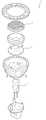
도 1은 종래기술에 따른 LED 조명장치(1)에 대한 분해 사시도로서, 종래 기술에 따른 LED 조명장치(1)는 도 1에 도시된 바와 같이, 렌즈유닛(3), LED 모듈(5), AC-DC 전원장치(7)를 포함한다. 특히, 종래기술에 따른 LED 조명장치(1)는 전력공급원(S)의 외부전력(일반적으로, 220V의 교류 전력)을 LED 모듈을 구동하기 위한 직류 전력(일반적으로, LED 모듈 양단에 3V 직류 전압 인가)으로 전환하여 전력을 공급하는 AC-DC 전원장치(7)를 필수 구성요소로 하며, 종래기술에 따른 LED 조명장치(1)에서 AC-DC 전원장치(7)는 LED 모듈(5)과 매우 근접하게 또는 접촉 방식으로 장착된다.1 is an exploded perspective view of the
현재 LED 조명장치에서 AC-DC 전원장치의 원가 비중은 약 20%를 차지하고 있으며, 향후 LED 모듈의 원가가 계속 하락하는 경향에 있으므로 LED 조명장치(20)에서 AC-DC 전원장치의 원가비중은 더욱 증가할 것으로 예상되는바, AC-DC 전원장치의 원가를 절감할 수 있는 LED 조명장치에 대한 필요성이 제기되어 왔다. 또한, 일반적으로 LED 모듈의 발광시 LED 모듈은 대략 70 ℃ ~ 75 ℃까지 온도가 상승하므로, 종래기술의 LED 조명장치에서는 LED 모듈과 AC-DC 전원장치가 매우 근접하게 위치하고 있어 LED 모듈의 발열로 인해 AC-DC 전원장치의 수명이 저감되는 문제점이 있었다. 이로 인해, LED 모듈의 수명이 남아 있음에도 불구하고, AC-DC 전원장치의 수명 고갈로 인해, LED 조명장치 전체를 교체해야 하는 문제점이 있었다.At present, the cost ratio of AC-DC power supply to LED lighting device accounts for about 20%, and since the cost of LED module tends to keep falling in the future, the cost ratio of AC-DC power supply to
본 발명의 목적은 종래 기술에 따른 문제점을 해결할 수 있는 LED 조명시스템을 제공하는 것이다.An object of the present invention is to provide an LED lighting system that can solve the problems according to the prior art.
또한, 본 발명의 목적은 제조원가를 절감할 수 있고 유지보수 비용을 절감할 수 있는 LED 조명시스템을 제공하는 것이다.It is also an object of the present invention to provide an LED lighting system that can reduce manufacturing costs and maintenance costs.
또한, 본 발명의 목적은 수명이 향상된 LED 조명시스템을 제공하는 것이다.It is also an object of the present invention to provide an LED lighting system having an improved lifetime.
상기 목적을 달성하기 위하여, 본 발명은 LED 소자를 구비하는 광원부 및 상기 광원부를 수용하는 하우징을 포함하는 복수 개의 조명장치; 및 상기 복수 개의 조명장치와 서로 이격되어 전기적으로 연결되고, 상기 복수 개의 조명장치를 구동하는 구동장치;를 포함하는 LED 조명시스템을 제공한다.In order to achieve the above object, the present invention comprises a plurality of lighting devices including a light source unit having an LED element and a housing for accommodating the light source unit; And a driving device spaced apart from each other and electrically connected to the plurality of lighting devices, and configured to drive the plurality of lighting devices.
본 발명의 다른 실시 형태에 따르면, 본 발명은 LED 소자를 구비하는 광원부 및 상기 광원부를 수용하는 하우징을 포함하는 복수개의 조명장치; 및 복수 개의 AC-DC 컨버터 및 상기 복수 개의 AC-DC 컨버터를 제어하는 제어부를 구비하고, 상기 복수 개의 조명장치를 구동하는 구동장치;를 포함하는 LED 조명시스템을 제공한다.According to another embodiment of the present invention, the present invention provides a lighting apparatus including a light source unit including an LED element and a housing accommodating the light source unit; And a control unit for controlling a plurality of AC-DC converters and the plurality of AC-DC converters, and a driving device for driving the plurality of lighting devices.
상술한 본 발명에 따른 LED 조명시스템의 효과는 다음과 같다.Effects of the LED lighting system according to the present invention described above are as follows.
본 발명에 따른 LED 조명시스템은 LED 조명장치에서 AC-DC 전원장치를 제거하여 제조원가를 절감할 수 있는 이점이 있다.LED lighting system according to the present invention has the advantage to reduce the manufacturing cost by removing the AC-DC power supply from the LED lighting device.
또한, 본 발명에 따른 LED 조명시스템은 LED 조명장치에서 AC-DC 전원장치를 별도로 관리할 수 있어 유지보수 비용을 절감할 수 있는 이점이 있다.In addition, the LED lighting system according to the present invention has the advantage that can be managed separately from the AC-DC power supply in the LED lighting device to reduce the maintenance cost.
또한, 본 발명에 따른 LED 조명시스템은 LED 조명장치에서 AC-DC 전원장치를 제거하여 LED 조명장치를 소형화할 수 있는 이점이 있다.In addition, the LED lighting system according to the present invention has the advantage that can be miniaturized by removing the AC-DC power supply from the LED lighting device.
또한, 본 발명에 따른 LED 조명시스템은 기존의 전기 설비를 그대로 이용할 수 있는 이점이 있다.In addition, the LED lighting system according to the present invention has the advantage that it can use the existing electrical equipment as it is.
또한, 본 발명에 따른 LED 조명시스템은 LED 조명장치와 AC-DC 전원장치가 공간적으로 이격되어 있어 LED 조명시스템의 수명을 향상시키는 이점이 있다.In addition, the LED lighting system according to the present invention has the advantage that the LED lighting device and the AC-DC power supply are spaced apart from each other to improve the life of the LED lighting system.
도 1은 종래기술에 따른 LED 조명장치의 분해사시도이다.
도 2는 본 발명에 따른 LED 조명시스템의 개략도이다.
도 3은 본 발명에 따른 조명장치의 분해사시도이다.
도 4는 본 발명의 일 실시예에 따른 구동장치의 블록선도이다.
도 5는 도 4의 변형 실시예에 따른 구동장치의 블록선도이다.
도 6은 본 발명의 다른 일 실시예에 따른 구동장치의 블록선도이다.
도 7은 도 6의 다른 일 실시예에 따른 구동장치의 작동 알고리즘을 나타내는 순서흐름도이다.
도 8은 도 7의 작동 알고리즘의 변형 실시예에 대한 순서흐름도이다.1 is an exploded perspective view of an LED lighting apparatus according to the prior art.
2 is a schematic diagram of an LED lighting system according to the present invention.
3 is an exploded perspective view of the lighting apparatus according to the present invention.
4 is a block diagram of a driving apparatus according to an embodiment of the present invention.
5 is a block diagram of a driving apparatus according to a modified embodiment of FIG. 4.
6 is a block diagram of a driving apparatus according to another embodiment of the present invention.
7 is a flowchart illustrating an operation algorithm of a driving apparatus according to another exemplary embodiment of FIG. 6.
8 is a flow chart of a variant embodiment of the operation algorithm of FIG.
이하, 첨부된 도면들을 참조하여 본 발명의 바람직한 실시예들을 상세히 설명하기로 한다. 그러나, 본 발명은 여기서 설명된 실시예들에 한정되지 않고 다른 형태로 구체화될 수도 있다. 오히려, 여기서 소개되는 실시예들은 개시된 내용이 철저하고 완전해질 수 있도록, 그리고 당업자에게 본 발명의 사상이 충분히 전달될 수 있도록 하기 위해 제공되는 것이다. 명세서 전체에 걸쳐서 동일한 참조번호들은 동일한 구성요소들을 나타낸다.Hereinafter, preferred embodiments of the present invention will be described in detail with reference to the accompanying drawings. However, the present invention is not limited to the embodiments described herein but may be embodied in other forms. Rather, the embodiments disclosed herein are provided so that the disclosure can be thorough and complete, and will fully convey the scope of the invention to those skilled in the art. Like numbers refer to like elements throughout.
도 2는 본 발명에 따른 LED 조명시스템(10)의 개략도이다.2 is a schematic diagram of an
도 2에 도시된 바와 같이, 본 발명에 따른 LED 조명시스템(10)은 LED 소자(24a)를 구비한 복수 개의 조명장치(20)와 상기 복수 개의 조명장치(20)를 구동하는 구동장치(30)를 포함한다.As shown in FIG. 2, the
복수 개의 조명장치(20)는 소켓형 LED 조명장치, 형광등형 LED 조명장치, 판넬형 LED 조명장치일 수 있다. 즉, 상기 조명장치(20)는 LED 소자(24a)를 포함하는 조명장치(20)라면 어떠한 조명장치(20)라도 가능하다.The plurality of
이렇게 LED 소자(24a)를 포함하는 조명장치(20)는 전력공급원(S)이 제공하는 고전압의 교류 전력을 LED 소자(24a)의 구동에 필요한 저전압의 직류 전압으로 전환하는 AC-DC 컨버터(40)를 필수 구성요소로 한다. 그러나, 본 발명에 따른 LED 조명시스템(10)에 포함된 조명장치(20)는 AC-DC 컨버터(40)를 포함하지 않는다. 대신, 본 발명에 따른 LED 조명시스템(10)은 복수 개의 조명장치(20)에 포함되어야 할 AC-DC 컨버터(40)를 별도의 장치에 통합한 구동장치(30)를 구비한다.The
즉, 본 발명에 따르면 LED 소자(24a)를 구비하는 조명장치(20)에서 원가비중이 큰 AC-DC 컨버터(40)를 제거하고, 제거된 AC-DC 컨버터(40)를 하나의 구동장치(30) 내에 통합하여 구성한다. 조명장치(20)의 상세한 구성에 대하여는 도 2를 참고하여 후술하기로 한다.That is, according to the present invention, the AC-
이로 인해, 본 발명은 조명장치(20)의 제조단가 또는 원가를 상당히 절감할 수 있다. 또한, 도 1에 도시된 바와 같이 AC-DC 컨버터(40)는 조명장치(20)에서 상당 부분의 공간을 차지하는 바, 본 발명은 AC-DC 컨버터(40)의 생략으로 인해 조명장치(20) 전체의 크기를 소형화할 수 있다.As a result, the present invention can significantly reduce the manufacturing cost or cost of the
구동장치(30)는 상기 복수 개의 조명장치(20)의 하우징의 외부에 배치되고, 이로 인해 상기 구동장치(30)는 상기 복수 개의 조명장치(20)와 서로 공간적으로 이격되면서 동시에 전기적으로 연결되어 있다. 즉, 상기 구동장치(30)는 발열량(대략 70 ℃ 내지 80 ℃까지 온도가 상승함) 이 큰 LED 소자(24a)와 공간적으로 이격되어 전선 등으로 연결되어 있다. 이로 인해, 본 발명에 따른 LED 조명시스템(10)에서는 LED 소자의 열영향영역과 구동장치의 열영향영역이 공간적으로 분리되어 LED 소자(24a)의 발열로 인한 구동장치(30)의 수명 저감 현상이 방지되므로, LED 조명시스템(10) 전체의 수명을 향상시킬 수 있는 이점이 있다.The
또한, 구동장치(30)도 구동시 50 ℃ 내지 65 ℃까지 온도가 상승하는바, 구동장치(30)의 발열로 인한 LED 소자(24a)의 수명 저감 현상도 방지할 수 있어, 결국 LED 조명시스템(10) 전체의 수명을 향상시킬 수 있다.In addition, since the temperature rises from 50 ° C. to 65 ° C. when the
구동장치(30)는 전력공급원(S)이 공급하는 고전압의 교류 전력을 LED 소자(24a)의 구동을 위한 저전압 직류 전력으로 전환하는 AC-DC 컨버터(40)를 포함한다. 상기 AC-DC 컨버터(40)는 종래기술에 따른 LED 조명장치(20)에 내장되는 소형 AC-DC가 아니라, 복수 개의 조명장치(20)의 소비전력량보다 큰 정격 전력을 가지는 통합 AC-DC 컨버터(40)이다.The
바람직하게는, 상기 구동장치(30)의 외부 하우징(26)에는 구동장치(30)의 구동열을 외부로 방출하는 방열부(도시되지 않음)가 구비될 수 있다.Preferably, the
바람직하게는, 상기 구동장치(30)는 전력공급원(S)이 제공하는 전력을 소비하는 전력수요부(예를 들어, 가정 또는 사무실 등)의 실내에 구비되어, 사용자가 구동장치(30)의 작동상태 및 조명장치(20)의 작동상태를 용이하게 파악할 수 있도록 할 수 있다.Preferably, the
도 3은 본 발명에 따른 조명장치(20)의 분해사시도이다. 도 3을 참고하여, 조명장치(20)의 상세한 구성에 대하여 설명하기로 한다.3 is an exploded perspective view of the
도 3에 도시된 바와 같이, 조명장치(20)는 LED 소자(24a) 및 상기 LED 소자(24a)가 전기적 접촉 방식으로 장착되는 인쇄회로기판(24b)을 구비하는 광원부(24), 상기 LED 소자(24a)에서 방출된 빛을 일정 방향으로 조사하도록 유도하는 렌즈유닛(22), 상기 광원부(24)를 수용하는 하우징(26) 및 상기 하우징(26)의 일측에 장착되어 전력수요부에 설치된 조명설치부(도시되지 않음)에 장착되는 기구부를 포함한다.As shown in FIG. 3, the
렌즈유닛(22)은 광 투과성 또는 광 반투과성 소재로 이루어진다. 또한, 렌즈유닛(22)은 조명장치(20)의 용도에 맞게 LED 소자(24a)의 빛의 방향성을 조절하도록 구성되거나 또는 빛의 조사범위를 조절하도록 구성될 수 있다.The
렌즈유닛(22)의 일측에는 LED 소자(24a)의 빛이 전방으로 집중되어 방출될 수 있도록 하는 반사부재(23)가 구비된다. 상기 렌즈유닛(22)과 반사부재(23)는 커버링(21)에 의하여 하우징(26)에 결합될 수 있다.One side of the
도 3에 도시된 바와 같이, 광원부(24)는 LED 소자(24a), 상기 LED 소자(24a)의 일측에 전기적 접촉 방식으로 연결된 인쇄회로기판(24b)을 포함한다.As shown in FIG. 3, the
인쇄회로기판(24b) 또는 LED 소자(24a)는 전력을 공급받는 전극부(24c)를 구비한다. 상기 전극부(24c)는 후술할 소켓형상 플러그에 전기적으로 직접 연결될 수도 있고, 구동장치(30)에 전기적으로 직접 연결될 수도 있다.The printed
이로 인해, LED 소자(24a)는 구동장치(30)로부터 직류 전력을 직접 공급받을 수 있다. 즉, 본 발명의 조명장치(20)는 AC-DC 컨버터를 구비하지 않고 LED 소자(24a)의 전극부(24c)를 통하여 구동장치(30)로부터의 직류 전력을 직접 공급받을 수 있다.As a result, the
바람직하게는, 상기 LED 소자(24a)는 구동시 대략 70 ℃ 내지 80 ℃까지 온도가 상승하므로, 상기 LED의 온도를 감소시키기 위하여 상기 인쇄회로기판(24b)의 일측에는 방열판이 구비될 수 있다.Preferably, since the temperature of the
하우징(26)은 렌즈유닛(22), 반사부재(23) 및 광원부(24)를 수용한다. 상기 하우징(26)은 LED 소자(24a)에서 발생되는 열을 외부로 방출하기 위하여 LED 소자(24a)가 장착된 인쇄회로기판(24b)의 일측에 구비된 방열판과 접촉 방식으로 연결된다. 이때, 상기 하우징(26)은 히트싱크(Heat Sink)로서 역할을 하며, 상기 하우징(26)의 외면에는 열 방출효율을 향상시키기 위하여 표면적을 증가시키는 복수 개의 방열핀이 형성될 수 있다. 상기 하우징(26)은 열전도성이 우수한 금속 재질인 것이 바람직하다.The
상기 하우징(26)의 중앙에는 중공부가 있어, 상기 인쇄회로기판(24b) 또는 상기 LED 소자(24a)의 전극부(24c)가 하우징(26)을 관통할 수 있다.The center of the
하우징(26)의 일측(예를 들어, 도 3에 도시된 바와 같이 하우징의 하부)에는 조명장치(20)가 전력수요부(예를 들어, 가정 또는 사무실 등)에 설치된 조명설치부(예를 들어, 소켓)에 탈착방식으로 또는 고정방식으로 용이하게 장착될 수 있도록 하는 기구부가 구비된다. 상기 기구부는 기존의 조명설치부에 대응되는 형상으로 형성될 수 있으며, 그 예로서 상기 기구부는 소켓형상 플러그(27)일 수 있다. 이하에서는, 설명의 편의성 및 이해의 용이성을 위해, 소켓 방식의 조명설치부에 대응되는 소켓형 조명장치(20)에 대하여 기술하기로 한다. 그러나, 이는 예시적인 것으로서, 본 발명은 이에 제한되지 않는다.On one side of the housing 26 (for example, the lower part of the housing as shown in FIG. 3), the
하우징(26)의 하부에는 구동장치(30)와 LED 소자(24a)를 전기적으로 연결하는 소켓형상 플러그(27)가 구비된다. 상기 소켓형상 플러그(27)에는 인쇄회로기판(24b) 또는 LED 소자(24a)의 전극부(24c)가 전기적으로 직접 연결되어 있고, 상기 소켓형상 플러그(27)가 전력수요부의 조명설치부(즉, 소켓)에 설치되는 경우, 구동장치(30)로부터 직류 전력을 공급받아 상기 LED 소자(24a)로 상기 직류 전력을 직접 전달한다.The lower portion of the
전술한 바와 같이, 본 발명에 따른 조명장치(20)는 AC-DC 컨버터(40)를 포함하고 있지 않아, 조명장치(20)의 원가를 상당히 감소시킬 수 있고, 조명장치(20)의 수명 고갈시 또는 고장시 저가의 조명장치(20)만을 교체하면 되므로 유지보수비용을 상당히 절감할 수 있다. 또한, AC-DC 컨버터의 구동열로 인한 LED 소자(24a)의 손상이 방지될 수 있어, LED 소자(24a)의 수명을 더 향상시킬 수 있다. 뿐만 아니라, 도 1에 도시된 바와 같이, AC-DC 컨버터가 조명장치(20) 내에서 차지하는 공간을 절약할 수 있어, LED 조명장치(20)의 크기를 상당히 소형화할 수 있어, 공간활용도 및 기구설계에 대한 자유도가 상당히 향상될 수 있다.As described above, the
본 발명에 따른 조명장치의 변형 실시예(도면에 도시되지 않음)로서, 상기 조명장치는, 빛을 방출하는 LED 소자(24a), 상기 LED 소자가 전기적 접촉 방식으로 장착되는 인쇄회로기판(24b), 상기 LED 소자 및 상기 인쇄회로기판을 수용하는 하우징(26) 및 상기 구동장치(30)로부터 공급되는 직류전력(또는 출력전력)의 전류를 상기 LED 소자의 정격 전류 범위 내에 있도록 상기 구동장치의 직류전력(또는 출력전력)의 전류를 제어하여 상기 LED 소자의 정격 전류 범위 내에 있는 정전류를 상기 LED 소자로 공급하는 정전류 제어수단(도시되지 않음)을 포함할 수 있다. 이때, 상기 인쇄회로기판은 구동장치로부터의 직류전력을 공급받는 전극부(24c)를 구비할 수 있다.As a modified embodiment (not shown) of the lighting apparatus according to the present invention, the lighting apparatus includes an
바람직하게는, 상기 정전류 제어수단은, 상기 하우징 내에 수용되어 상기 전극부에 연결되는 정전류 제어기이거나, 또는 상기 인쇄회로기판에 형성된 정전류 제어회로일 수 있다.Preferably, the constant current control means may be a constant current controller accommodated in the housing and connected to the electrode portion, or may be a constant current control circuit formed on the printed circuit board.
본 발명에 따른 LED 조명장치의 변형 실시예에 따르면, LED 조명장치의 유형이 소켓형 LED 조명장치, 형광등형 LED 조명장치, 판넬형 LED 조명장치 등으로 다양하여 각각의 LED 조명장치의 정격 전류(또는 정격 전력)가 상이하다 하더라도 각각의 LED 조명장치에 각각의 LED 조명장치의 고유 정격 전류(또는 정격 전력) 범위 내에 있는 정전류를 제공할 수 있어, 과전류로 인한 LED 소자의 손상을 방지할 수 있을 뿐만 아니라 구동장치로부터의 출력전력에 무관하게 안정적인 정전류(또는 전력)를 공급받을 수 있어 상기 구동장치의 효용성을 더욱 향상시킬 수 있으며, LED 조명장치 본연의 색도 및 광도를 균일하게 획득할 수 있다.According to a modified embodiment of the LED lighting apparatus according to the present invention, the type of the LED lighting device is a socket-type LED lighting device, a fluorescent LED lighting device, a panel-type LED lighting device, and the like, so that the rated current of each LED lighting device ( Or even different power ratings, it is possible to provide each LED lighting device with a constant current within the inherent rated current (or rated power) range of each LED lighting device, thus preventing damage to the LED element due to overcurrent. In addition, it is possible to receive a stable constant current (or electric power) regardless of the output power from the drive device can further improve the utility of the drive device, it is possible to uniformly obtain the chromaticity and brightness of the LED lighting device.
특히, 상기 정전류 제어수단이 인쇄회로기판에 형성된 정전류 제어회로인 경우, LED 조명장치를 소형화할 수 있어 LED 조명장치의 설계 자유도 및 설치 자유도를 향상시킬 수 있다.In particular, when the constant current control means is a constant current control circuit formed on a printed circuit board, the LED lighting apparatus can be miniaturized, thereby improving design freedom and installation freedom of the LED lighting apparatus.
도 4는 본 발명의 일 실시예에 따른 구동장치(30)의 블록선도이다.도 4에 도시된 바와 같이, 본 발명의 일 실시예에 따른 구동장치(30)는 전력공급원(S)에서 공급되는 전력을 소비하는 전력수요부(예를 들어, 가정, 연구소, 공장 또는 사무소 등)에 구비되는 누전차단기(Circuit Breaker, CB)와 상기 복수 개의 조명장치(20) 사이에 위치한다. 당연히, 전력공급원(S), 누전차단기(CB), 구동장치(30) 및 조명장치(20)는 전기연결선(예를 들어, 전선 또는 케이블 등)으로 연결된다.4 is a block diagram of a driving
본 발명에 따르면 본 발명에 따른 구동장치(30)만 누전차단기(CB)와 조명장치(20) 사이에 설치되면 되므로, 기존의 조명 설비, 전기 연결선 및 조명시스템을 그대로 이용할 수 있어, 본 발명은 기존 설비 교체 비용이 거의 소요되지 않는 이점을 가진다.According to the present invention, since only the driving
본 발명의 일 실시예에 따른 구동장치(30)는 하나의 AC-DC 컨버터(40)를 포함하고, 상기 AC-DC 컨버터(40)는 전력공급원(S)의 교류 전력이 입력되는 전력입력부(41), 상기 교류 전력을 직류 전력으로 전환하는 단일 컨버팅부(43), 상기 직류 전력을 상기 복수 개의 조명장치(20)에 공급하는 전력출력부(45)를 포함한다.The driving
바람직하게는, 단일 컨버팅부(43)는 복수 개의 조명장치(20) 전체의 소비전력량보다 큰 정격 전력을 가지도록 구성될 수 있다.Preferably, the single converting
AC-DC 컨버터(40)의 단일 컨버팅부(43)는 종래 기술에 따른 LED 조명장치(20)에 구비되는 AC-DC 컨버터(40)에 대응되는 장치이나, 종래 기술에 따른 LED 조명장치(20)의 경우 LED 조명장치(20)가 복수 개인 경우 복수 개의 AC-DC 컨버터(40)를 LED 조명장치(20)에 내장해야 하므로, 본 발명에 따른 단일 컨버팅부(43)를 구비한 AC-DC 컨버터(40)의 제조비용은 복수 개의 AC-DC 컨버터(40) 전체의 제조비용에 비하여 매우 저렴하다. 또한, 종래기술에 따른 LED 조명장치(20)의 경우 소형 AC-DC 컨버터(40)의 내장을 위해 별도의 조립공정을 필요로 하나, 본 발명에 따른 AC-DC 컨버터(40)로 인해 조명장치(20)는 내장형 소형 AC-DC 컨버터(40)를 필요로 하지 않으므로 별도의 AC-DC 컨버터(40) 내부 장착 공정을 필요로 하지 않으므로 조명장치(20)의 제조시간을 단축시킬 수 있어 생산성 및 제조단가를 절감할 수 있는 이점을 가진다.The single converting
또한, 본 발명에 따른 구동장치(30)는 LED 소자(24a)의 발광시 방출되는 열로 인한 손상이 일어나지 않으므로, 본 발명은 구동장치(30)의 수명을 향상시킬 수 있다. 이로 인해, LED 조명시스템(10) 전체의 수명 또한 연장시킬 수 있다.In addition, since the
도 5는 도 4의 변형 실시예에 따른 구동장치(30)의 블록선도이다.5 is a block diagram of the driving
도 5에 도시된 바와 같이, 변형 실시예에 따른 구동장치(30)는 전력공급원(S)에서 공급되는 전력을 소비하는 전력수요부(예를 들어, 가정, 연구소, 공장 또는 사무소 등)에 구비되는 누전차단기(CB)와 상기 복수 개의 조명장치(20) 사이에 위치한다.As shown in FIG. 5, the driving
변형 실시예에 따른 구동장치(30)는 상기 AC-DC 컨버터(40)는 전력공급원(S)의 교류 전력이 입력되는 전력입력부(41), 상기 교류 전력을 직류 전력으로 전환하는 복수 개의 컨버팅부(43), 상기 직류 전력을 상기 복수 개의 조명장치(20)에 공급하는 복수 개의 전력출력부(45)를 포함한다. 이때, 바람직하게는, 상기 컨버팅부(43)의 수량은 전력출력부(45)의 수량 및 조명장치(20)의 수량과 동일할 수 있다.In the driving
복수 개의 컨버팅부(43)는 복수 개의 전력출력부(45)에 일대일 대응방식으로 전기적으로 연결되고, 상기 복수 개의 전력출력부(45)는 상기 복수 개의 조명장치(20)와 일대일 방식으로 전기적으로 연결된다. 즉, 상기 복수 개의 컨버팅부(43)는 상기 복수 개의 조명장치(20)와 일대일 방식으로 전기적으로 연결되어, 상기 복수 개의 컨버팅부(43)는 전원공급원의 교류 전력을 직류 전력으로 전환하여 상기 직류 전력을 상기 복수 개의 조명장치(20)로 공급한다.The plurality of converting
본 발명의 변형 실시예에 따르면, 복수 개의 컨버팅부(43) 중 일부의 컨버팅부(43)가 수명 고갈 또는 고장시에 해당 컨버팅부(43)만 교체하면 되므로, 조명시스템의 유지보수비용을 절감할 수 있다.According to a modified embodiment of the present invention, since only part of the converting
바람직하게는, 고장나거나 또는 수명이 고갈된 컨버팅부(43)의 교체용이성을 향상시키기 위하여, 상기 복수 개의 컨버팅부(43)는 AC-DC 컨버터(40)에서 개별적으로 탈착가능하게 장착될 수 있다.Preferably, the plurality of converting
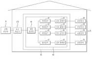
도 6은 본 발명의 다른 일 실시예에 따른 구동장치(30)의 블록선도이다.6 is a block diagram of a
도 6에 도시된 바와 같이, 본 발명의 다른 일 실시예에 따른 구동장치(30)는 복수개의 조명장치(20)를 구동하고, 상기 구동장치(30)는 복수 개의 AC-DC 컨버터(40; 50), 상기 복수 개의 조명장치(20)가 소요하는 소비전력량 또는 구동장치(30)의 출력전력량을 감지하는 전력감지부(70) 및 상기 구동장치(30)의 작동상태를 표시하는 표시부(80)를 포함한다.As shown in FIG. 6, the driving
또한, 상기 구동장치(30)는 제어부(60)를 포함하고, 상기 제어부(60)는 상기 전력감지부(70)로부터 소비전력량 또는 출력전력량에 대한 정보를 수신하고, 상기 복수 개의 AC-DC 컨버터(40) 및 상기 표시부(80)를 제어할 수 있다.In addition, the driving
복수 개의 AC-DC 컨버터(40; 50) 중 하나의 컨버터는 메인 컨버터(40)이고, 복수 개의 AC-DC 컨버터(40; 50) 중 나머지 컨버터는 서브 컨버터(50)이다. 여기서, 메인 컨버터(40)는 평상시 전력공급원(S)에서 공급되는 교류 전력을 직류 전력으로 전환하여 상기 복수개의 조명장치(20)에 공급하는 컨버터이고, 서브 컨버터(50)는 상기 복수 개의 조명장치(20)가 상기 메인 컨버터(40)의 기설정된 정격 전력을 초과하는 전력을 필요로 하는 경우 메인 컨버터(40)의 기설정된 정격 전력을 초과하는 전력을 상기 복수개의 조명장치(20)에 직류 전력으로 공급하는 컨버터이다.One of the plurality of AC-
또한, 상기 서브 컨버터(50)는 상기 메인 컨버터(40)의 수명 고갈시 또는 고장시 등의 오작동시(또는 비상시)에 복수 개의 조명장치(20)를 구동시키도록 (또는 상기 복수 개의 조명장치(20)에 직류전력을 공급하도록) 작동될 수 있다.In addition, the sub-converter 50 may drive the plurality of lighting apparatuses 20 (or the plurality of lighting apparatuses) in a malfunction (or emergency), such as when the life of the
즉, 메인 컨버터(40)만 평상시에 복수 개의 조명장치(20)를 구동하기 위해 작동하고, 나머지 컨버터들인 서브 컨버터(50)는 메인 컨버터(40)의 정격 전력만으로는 복수 개의 조명장치(20)를 구동하기 부족한 경우 또는 메인 컨버터의 오작동시에만 작동한다.That is, only the
상기 메인 컨버터(40) 또는 상기 서브 컨버터(50)는 도 4에 도시된 일 실시예에 따른 AC-DC 컨버터(40) 또는 도 5에 도시된 변형 실시예에 따른 AC-DC 컨버터(40) 중 하나일 수 있다. 즉, 상기 메인 컨버터(40) 또는 상기 서브 컨버터(50)는 전력공급원(S)의 교류 전력이 입력되는 전력입력부(41; 51a), 상기 교류 전력을 직류 전력으로 전환하는 단일 컨버팅부(43; 51b), 상기 직류 전력을 상기 복수 개의 조명장치(20)에 공급하는 전력출력부(45; 51c)를 포함하도록 구성되거나, 또는 전력공급원(S)의 교류 전력이 입력되는 전력입력부(41; 51a), 상기 교류 전력을 직류 전력으로 전환하는 복수 개의 컨버팅부(43; 51b), 상기 직류 전력을 상기 복수 개의 조명장치(20)에 공급하는 복수 개의 전력출력부(45; 51c)를 포함하도록 구성될 수도 있다.The
바람직하게는, 메인 컨버터(40)의 정격 전력은 서브 컨버터(50)의 정격 전력보다 클 수 있다. 이로 인해, 서브 컨버터는 메인 컨버터보다 제조단가가 낮은 AC-DC 컨버터일 수 있다.Preferably, the rated power of the
AC-DC 컨버터가 하나만 있는 경우, AC-DC 컨버터의 고장이나 수명 고갈 또는 복수 개의 조명장치의 소비전력량의 급증으로 인해, 복수 개의 조명장치에의 직류 전력 공급의 중단 현상이 발생될 수 있다. 그러나, 본 발명의 다른 일 실시예에 따른 구동장치는 메인 컨버터와 서브 컨버터를 포함함으로써, 복수 개의 조명장치에의 전력 공급이 중단되는 것을 방지할 수 있고, 이로 인해 복수 개의 조명장치의 소등으로 인한 사용자의 불편을 제거할 수 있으며, 복수 개의 조명장치를 전체적으로 안정적으로 구동시킬 수 있다. 또한, 평상시에는 메인 컨버터만을 사용하고 비상시에만 서브 컨버터를 작동시키므로, 본 발명은 상황에 따라 구동장치를 효율적으로 작동시킬 수 있다.When there is only one AC-DC converter, the DC power supply to the plurality of lighting devices may be interrupted due to a failure of the AC-DC converter, exhaustion of life, or a sudden increase in power consumption of the plurality of lighting devices. However, the driving apparatus according to another embodiment of the present invention includes a main converter and a sub-converter, thereby preventing the power supply to the plurality of lighting apparatuses from being interrupted. The inconvenience of the user can be eliminated, and the plurality of lighting devices can be stably driven as a whole. In addition, since only the main converter is normally used and the sub-converter is operated only in an emergency, the present invention can efficiently operate the driving apparatus according to the situation.
이하에서는, 도 6에 도시된 다른 일 실시예에 따른 구동장치의 작동방법에 대하여 도 7을 참고하여 구체적으로 기술하기로 한다.Hereinafter, a method of operating a driving apparatus according to another exemplary embodiment shown in FIG. 6 will be described in detail with reference to FIG. 7.
도 7은 도 6의 다른 일 실시예에 따른 구동장치(30)의 작동 알고리즘을 나타내는 순서흐름도(S100)이다. 구체적으로, 도 7은 메인 컨버터의 정격 전력이 복수 개의 조명장치를 구동하기 부족한 경우 구동장치의 제어부의 작동 알고리즘을 나타낸다.7 is a flowchart illustrating an operation algorithm of the driving
우선, 제어부(60)는 평상시 전력공급원(S)의 고전압 교류 전력을 조명장치(20)의 구동에 필요한 저전압 직류 전력으로 전환하기 위하여 구동장치(30)의 메인 컨버터를 작동시킨다(S101).First, the
이후, 제어부는 전력감지부를 통하여 복수 개의 조명장치의 소비전력량을 감지한다(S103).Thereafter, the controller detects the amount of power consumption of the plurality of lighting devices through the power detection unit (S103).
이후, 제어부(60)는 전력감지부(70)에서 감지된 소비전력량에 기초하여 상기 복수 개의 AC-DC 컨버터(40) 중 전력공급원의 교류 전력을 공급할 컨버터의 수량을 결정한다.Thereafter, the
구체적으로, 제어부(60)는 전력감지부(70)에서 감지된 소비전력량이 메인 컨버터의 기설정된 정격 전력을 초과하는지 여부를 판단한다(S105). 이때, 제어부(60)가 상기 소비전력량이 상기 메인 컨버터의 기설정된 정격 전력을 초과하는 것으로 판단하는 경우, 상기 제어부(60)는 부족한 소비전력량을 계산한 후(S107), 작동시킬 서브 컨버터의 수량을 계산한다(S109). 이후, 제어부(60)는 계산된 수량만큼 서브 컨버터를 작동시켜(S111) 복수 개의 조명장치(20)에 직류 전력을 추가로 공급한다.In detail, the
즉, 상기 제어부(60)는 전력감지부(70)에서 감지된 소비전력량이 상기 메인 컨버터의 기설정된 정격 전력을 초과하는 것으로 판단하는 경우 전력공급원(S)의 교류 전력이 상기 서브 컨버터에 추가로 공급되도록 상기 메인 컨버터 또는 상기 서브 컨버터를 제어한다.That is, when the
도 8은 도 7의 작동 알고리즘의 변형 실시예에 대한 순서흐름도(S200)이다. 구체적으로, 도 8은 메인 컨버터의 오작동시 구동장치의 제어부의 작동 알고리즘을 나타낸다.8 is a flowchart S200 of a modified embodiment of the operation algorithm of FIG. 7. Specifically, FIG. 8 illustrates an operation algorithm of the controller of the driving apparatus when the main converter malfunctions.
여기서, 전력감지부(70)는 조명장치(20)의 소비전력량을 감지할 수 있을 뿐만 아니라, 메인 컨버터 또는 서브 컨버터의 출력전력량도 감지할 수 있도록 구성되는 것이 바람직하다.Here, the
우선, 제어부(60)는 평상시 전력공급원(S)의 고전압 교류 전력을 조명장치(20)의 구동에 필요한 저전압 직류 전력으로 전환하기 위하여 구동장치(30)의 메인 컨버터를 작동시킨다(S201).First, the
이후, 제어부(60)는 전력감지부(70)를 통하여 메인컨버터의 출력전력량을 감지한다(S203).Thereafter, the
이후, 제어부(60)는 전력감지부(70)에서 감지된 메인컨버터의 출력전력량에 기초하여 상기 메인컨버터의 오작동 여부를 판단한다(S205). 예를 들어, 제어부(60)가 메인컨버터의 출력전력량이 현재 구동되고 있는 복수 개의 조명장치(20)의 소비전력량에 과도하게 부족하다고 판단하는 경우 또는 출력전력량이 감지되지 않는 경우, 상기 제어부(60)는 상기 메인 컨버터가 오작동하고 있다고 판단할 수 있다.Thereafter, the
이때, 제어부(60)가 상기 메인 컨버터가 오작동하고 있다고 판단하는 경우, 상기 제어부(60)는 복수 개의 조명장치(20)에 직류 전력을 공급하기 위하여 서브 컨버터를 작동시킨다(S207).In this case, when the
바람직하게는, 제어부(60)는 상기 메인 컨버터 또는 상기 서브 컨버터의 작동 상태에 대한 정보, 상기 소비전력량이 상기 메인 컨버터의 정격 전력을 초과하는지에 대한 정보가 상기 표시부(80)에 표시되도록 상기 표시부(80)를 제어할 수 있다. 이로 인해, 사용자가 메인 컨버터 또는 서브 컨버터의 작동 상태 등을 용이하게 파악할 수 있다.Preferably, the
본 명세서는 본 발명의 바람직한 실시예를 참조하여 설명하였지만, 해당 기술분야의 당업자는 이하에서 서술하는 특허청구범위에 기재된 본 발명의 사상 및 영역으로부터 벗어나지 않는 범위 내에서 본 발명을 다양하게 수정 및 변경 실시할 수 있을 것이다. 그러므로 변형된 실시가 기본적으로 본 발명의 특허청구범위의 구성요소를 포함한다면 모두 본 발명의 기술적 범주에 포함된다고 보아야 한다.While the present invention has been particularly shown and described with reference to preferred embodiments thereof, it will be understood by those skilled in the art that various changes and modifications may be made without departing from the spirit and scope of the invention as defined in the following claims. . It is therefore to be understood that the modified embodiments are included in the technical scope of the present invention if they basically include elements of the claims of the present invention.
10 : LED 조명시스템20 : 조명장치
30 : 구동장치40 : AC-DC 컨버터, 메인 컨버터
50 : 서브 컨버터60 : 제어부
70 : 전력감지부80 : 표시부10: LED lighting system 20: lighting device
30: drive device 40: AC-DC converter, main converter
50: sub-converter 60: control unit
70: power detection unit 80: display unit
Claims (18)
Translated fromKorean상기 복수 개의 조명장치 각각을 구동하는 구동장치;를 포함하고,
상기 구동장치는 상기 하우징의 외부에 배치되고 상기 복수 개의 조명장치 각각에 전기적으로 연결되며,
상기 구동장치는 전력공급원에서 공급되는 전력을 소비하는 전력수요부에 구비되는 누전차단기와 상기 조명장치 사이에 위치하는 것을 특징으로 하는 LED 조명시스템.A plurality of lighting devices including a light source unit having an LED element and a housing accommodating the light source unit; And
And a driving device for driving each of the plurality of lighting devices.
The driving device is disposed outside the housing and electrically connected to each of the plurality of lighting devices,
The driving device is an LED lighting system, characterized in that located between the earth leakage breaker and the lighting device provided in the power demand for consuming power supplied from a power supply.
상기 광원부는 상기 LED 소자를 구비하는 인쇄회로기판을 더 포함하고, 상기 구동장치는 상기 인쇄회로기판의 전극부에 직류 전력을 직접 공급하는 것을 특징으로 하는 LED 조명시스템.The method of claim 1,
The light source unit further includes a printed circuit board including the LED element, and the driving device directly supplies DC power to an electrode of the printed circuit board.
상기 조명장치는 상기 하우징의 하부에 결합되는 소켓형상 플러그를 더 포함하고, 상기 소켓형상 플러그는 상기 구동장치로부터 직류 전력을 직접 공급받고, 상기 소켓형상 플러그는 상기 전극부에 직접 연결되는 것을 특징으로 하는 LED 조명시스템.The method of claim 2,
The lighting device further includes a socket-shaped plug coupled to the lower portion of the housing, wherein the socket-shaped plug is directly supplied with direct current power from the driving device, and the socket-shaped plug is directly connected to the electrode unit. LED lighting system.
상기 구동장치는 전력공급원의 교류 전력을 상기 LED 소자를 구동하는 직류 전력으로 전환하는 AC-DC 컨버터를 포함하는 것을 특징으로 하는 LED 조명시스템.The method of claim 1,
The driving device includes an AC-DC converter for converting AC power of a power supply into direct current power for driving the LED element.
상기 AC-DC 컨버터는 교류 전력이 입력되는 전력입력부, 상기 교류 전력을 직류 전력으로 전환하는 단일 컨버팅부, 상기 직류 전력을 상기 복수 개의 조명장치에 공급하는 전력출력부로 구성되는 것을 특징으로 하는 LED 조명시스템.5. The method of claim 4,
The AC-DC converter includes a power input unit to which AC power is input, a single converting unit to convert the AC power into DC power, and a power output unit to supply the DC power to the plurality of lighting devices. system.
상기 AC-DC 컨버터는 교류 전력이 입력되는 전력입력부, 상기 교류 전력을 직류 전력으로 전환하는 복수 개의 컨버팅부, 상기 직류 전력을 상기 복수 개의 조명장치에 공급하는 복수 개의 전력출력부로 구성되는 것을 특징으로 하는 LED 조명시스템.5. The method of claim 4,
The AC-DC converter includes a power input unit to which AC power is input, a plurality of converting units to convert the AC power into DC power, and a plurality of power output units to supply the DC power to the plurality of lighting devices. LED lighting system.
상기 복수 개의 컨버팅부는 상기 AC-DC 컨버터에 개별적으로 탈착가능하게 구비되는 것을 특징으로 하는 LED 조명시스템.The method of claim 7, wherein
The plurality of converting unit is an LED lighting system, characterized in that detachably provided in the AC-DC converter.
복수 개의 AC-DC 컨버터 및 상기 복수 개의 AC-DC 컨버터를 제어하는 제어부를 구비하고, 상기 복수 개의 조명장치 각각을 구동하는 구동장치;를 포함하고,
상기 구동장치는 상기 하우징의 외부에 배치되고 상기 복수 개의 조명장치 각각에 전기적으로 연결되며,
상기 구동장치는 전력공급원에서 공급되는 전력을 소비하는 전력수요부에 구비되는 누전차단기와 상기 조명장치 사이에 위치하는 것을 특징으로 하는 LED 조명시스템.A plurality of lighting devices including a light source unit having an LED element and a housing accommodating the light source unit; And
And a control unit for controlling a plurality of AC-DC converters and the plurality of AC-DC converters, and for driving each of the plurality of lighting devices.
The driving device is disposed outside the housing and electrically connected to each of the plurality of lighting devices,
The driving device is an LED lighting system, characterized in that located between the earth leakage breaker and the lighting device provided in the power demand for consuming power supplied from a power supply.
상기 복수 개의 AC-DC 컨버터 중 하나의 컨버터는 평상시 전력공급원에서 공급되는 교류 전력을 직류 전력으로 전환하여 상기 복수개의 조명장치에 공급하는 메인 컨버터이고, 상기 복수 개의 AC-DC 컨버터 중 나머지 컨버터는 상기 메인 컨버터를 보조하여 상기 복수 개의 조명장치에 직류 전력을 공급하는 서브 컨버터인 것을 특징으로 하는 LED 조명시스템.10. The method of claim 9,
One converter of the plurality of AC-DC converters is a main converter which converts AC power supplied from a power supply to a DC power and supplies the plurality of lighting devices to the plurality of lighting devices. The LED lighting system, characterized in that the sub-converter for supplying DC power to the plurality of lighting devices by assisting the main converter.
상기 서브 컨버터는 상기 복수 개의 조명장치가 상기 메인 컨버터의 기설정된 정격 전력을 초과하는 전력을 필요로 하는 경우 상기 정격 전력을 초과하는 전력을 상기 복수개의 조명장치에 직류 전력으로 공급하거나 또는 상기 메인 컨버터의 오작동시 작동되는 것을 특징으로 하는 LED 조명시스템.The method of claim 10,
The sub-converter supplies the power exceeding the rated power to the plurality of lighting apparatuses as DC power when the plurality of lighting apparatuses require power exceeding a predetermined rated power of the main converter, or the main converter. LED lighting system, characterized in that the operation of the malfunction.
상기 구동장치는 상기 복수 개의 조명장치가 소요하는 소비전력량 또는 상기 메인 컨버터의 출력전력량을 감지하는 전력감지부 및 상기 구동장치의 작동상태를 표시하는 표시부를 더 구비하는 것을 특징을 하는 LED 조명시스템.The method of claim 11,
The driving device further comprises a power sensing unit for sensing the amount of power consumed by the plurality of lighting devices or the output power of the main converter and a display unit for displaying the operating state of the driving device.
상기 제어부는 상기 전력감지부에서 감지된 소비전력량에 기초하여 상기 복수 개의 AC-DC 컨버터 중 전력공급원의 교류 전력을 공급할 컨버터의 수량을 결정하는 것을 특징으로 하는 LED 조명시스템.The method of claim 12,
The control unit determines the number of converters to supply the AC power of the power supply of the plurality of AC-DC converters based on the power consumption sensed by the power sensing unit.
상기 제어부는 상기 소비전력량이 상기 메인 컨버터의 기설정된 정격 전력을 초과하는지 여부를 판단하는 것을 특징으로 하는 LED 조명시스템.The method of claim 12,
The control unit LED lighting system, characterized in that for determining whether the amount of power consumption exceeds a predetermined rated power of the main converter.
상기 제어부는 상기 소비전력량이 상기 메인 컨버터의 기설정된 정격 전력을 초과하는 것으로 판단하는 경우 전력공급원의 교류 전력이 상기 서브 컨버터에 추가로 공급되도록 상기 메인 컨버터 또는 상기 서브 컨버터를 제어하는 것을 특징으로 하는 LED 조명시스템.15. The method of claim 14,
The control unit controls the main converter or the sub-converter so that an AC power of a power supply is additionally supplied to the sub-converter when it is determined that the amount of power consumption exceeds a predetermined rated power of the main converter. LED lighting system.
상기 제어부는 상기 복수 개의 조명장치의 소비전력량 또는 상기 메인 컨버터의 출력전력량에 기초하여 상기 메인 컨버터의 오작동 여부를 판단하는 것을 특징으로 하는 LED 조명시스템.The method of claim 12,
The controller determines whether the main converter malfunctions based on the power consumption of the plurality of lighting devices or the output power of the main converter.
상기 제어부는 상기 메인 컨버터가 오작동하고 있다고 판단하는 경우 상기 서브 컨버터를 작동시키는 것을 특징으로 하는 LED 조명시스템.16. The method of claim 15,
And the controller operates the sub-converter when it is determined that the main converter is malfunctioning.
상기 LED 소자 및 전력을 공급받는 전극부가 구비되는 인쇄회로기판; 및
상기 LED 소자 및 상기 인쇄회로기판을 수용하는 하우징;을 포함하고,
상기 인쇄회로기판에는 상기 LED 소자에 공급되는 전력의 전류가 상기 LED 소자의 정격 전류 범위 내에 있도록 전력의 전류를 제어하는 정전류 제어기 및 정전류 제어회로 중 하나가 구비되며,
상기 전극부는 상기 하우징의 외부에 배치되는 AC-DC 컨버터로부터 직류전력을 공급받는 것을 특징으로 하는 LED 조명장치.LED device;
A printed circuit board including the LED element and an electrode unit receiving electric power; And
And a housing accommodating the LED element and the printed circuit board.
The printed circuit board is provided with one of a constant current controller and a constant current control circuit for controlling the current of the power so that the current of the power supplied to the LED element is within the rated current range of the LED element,
The electrode unit is an LED lighting device, characterized in that the DC power supplied from the AC-DC converter disposed outside the housing.
Priority Applications (3)
| Application Number | Priority Date | Filing Date | Title |
|---|---|---|---|
| KR1020100121153AKR101210645B1 (en) | 2010-12-01 | 2010-12-01 | Led lighting system |
| PCT/KR2011/009249WO2012074304A2 (en) | 2010-12-01 | 2011-12-01 | Led lighting system |
| JP2013541925AJP2014502413A (en) | 2010-12-01 | 2011-12-01 | LED lighting system |
Applications Claiming Priority (1)
| Application Number | Priority Date | Filing Date | Title |
|---|---|---|---|
| KR1020100121153AKR101210645B1 (en) | 2010-12-01 | 2010-12-01 | Led lighting system |
Publications (2)
| Publication Number | Publication Date |
|---|---|
| KR20120059744A KR20120059744A (en) | 2012-06-11 |
| KR101210645B1true KR101210645B1 (en) | 2012-12-07 |
Family
ID=46172409
Family Applications (1)
| Application Number | Title | Priority Date | Filing Date |
|---|---|---|---|
| KR1020100121153AExpired - Fee RelatedKR101210645B1 (en) | 2010-12-01 | 2010-12-01 | Led lighting system |
Country Status (3)
| Country | Link |
|---|---|
| JP (1) | JP2014502413A (en) |
| KR (1) | KR101210645B1 (en) |
| WO (1) | WO2012074304A2 (en) |
Families Citing this family (56)
| Publication number | Priority date | Publication date | Assignee | Title |
|---|---|---|---|---|
| US9403238B2 (en) | 2011-09-21 | 2016-08-02 | Align Technology, Inc. | Laser cutting |
| US9375300B2 (en) | 2012-02-02 | 2016-06-28 | Align Technology, Inc. | Identifying forces on a tooth |
| US9220580B2 (en) | 2012-03-01 | 2015-12-29 | Align Technology, Inc. | Determining a dental treatment difficulty |
| US9414897B2 (en) | 2012-05-22 | 2016-08-16 | Align Technology, Inc. | Adjustment of tooth position in a virtual dental model |
| KR101608894B1 (en)* | 2014-02-26 | 2016-04-05 | 주식회사 비바아트 | Light guiding panel based LED surface lighting fixture set with shared converter |
| US10772506B2 (en) | 2014-07-07 | 2020-09-15 | Align Technology, Inc. | Apparatus for dental confocal imaging |
| US9675430B2 (en) | 2014-08-15 | 2017-06-13 | Align Technology, Inc. | Confocal imaging apparatus with curved focal surface |
| US9610141B2 (en) | 2014-09-19 | 2017-04-04 | Align Technology, Inc. | Arch expanding appliance |
| US10449016B2 (en) | 2014-09-19 | 2019-10-22 | Align Technology, Inc. | Arch adjustment appliance |
| US9744001B2 (en) | 2014-11-13 | 2017-08-29 | Align Technology, Inc. | Dental appliance with cavity for an unerupted or erupting tooth |
| US10504386B2 (en) | 2015-01-27 | 2019-12-10 | Align Technology, Inc. | Training method and system for oral-cavity-imaging-and-modeling equipment |
| US10248883B2 (en) | 2015-08-20 | 2019-04-02 | Align Technology, Inc. | Photograph-based assessment of dental treatments and procedures |
| KR101635711B1 (en)* | 2015-10-23 | 2016-07-01 | 주식회사 금강에너텍 | Circuit removal type converter apparatus for led lighting |
| US11554000B2 (en) | 2015-11-12 | 2023-01-17 | Align Technology, Inc. | Dental attachment formation structure |
| US11931222B2 (en) | 2015-11-12 | 2024-03-19 | Align Technology, Inc. | Dental attachment formation structures |
| US11596502B2 (en) | 2015-12-09 | 2023-03-07 | Align Technology, Inc. | Dental attachment placement structure |
| US11103330B2 (en) | 2015-12-09 | 2021-08-31 | Align Technology, Inc. | Dental attachment placement structure |
| KR101647610B1 (en)* | 2015-12-21 | 2016-08-10 | 김상선 | Led lighting device capable to cross driving by multiple smps |
| US10383705B2 (en) | 2016-06-17 | 2019-08-20 | Align Technology, Inc. | Orthodontic appliance performance monitor |
| WO2017218947A1 (en) | 2016-06-17 | 2017-12-21 | Align Technology, Inc. | Intraoral appliances with sensing |
| KR101681552B1 (en)* | 2016-07-01 | 2016-12-01 | (주)상도전기 | Converter system of led lighting |
| US10507087B2 (en) | 2016-07-27 | 2019-12-17 | Align Technology, Inc. | Methods and apparatuses for forming a three-dimensional volumetric model of a subject's teeth |
| CA3030676A1 (en) | 2016-07-27 | 2018-02-01 | Align Technology, Inc. | Intraoral scanner with dental diagnostics capabilities |
| CN117257492A (en) | 2016-11-04 | 2023-12-22 | 阿莱恩技术有限公司 | Method and apparatus for dental imaging |
| AU2017366755B2 (en) | 2016-12-02 | 2022-07-28 | Align Technology, Inc. | Methods and apparatuses for customizing rapid palatal expanders using digital models |
| WO2018102770A1 (en) | 2016-12-02 | 2018-06-07 | Align Technology, Inc. | Force control, stop mechanism, regulating structure of removable arch adjustment appliance |
| EP3547952B1 (en) | 2016-12-02 | 2020-11-04 | Align Technology, Inc. | Palatal expander |
| US11026831B2 (en) | 2016-12-02 | 2021-06-08 | Align Technology, Inc. | Dental appliance features for speech enhancement |
| US10548700B2 (en) | 2016-12-16 | 2020-02-04 | Align Technology, Inc. | Dental appliance etch template |
| US10456043B2 (en) | 2017-01-12 | 2019-10-29 | Align Technology, Inc. | Compact confocal dental scanning apparatus |
| US10779718B2 (en) | 2017-02-13 | 2020-09-22 | Align Technology, Inc. | Cheek retractor and mobile device holder |
| WO2018183358A1 (en) | 2017-03-27 | 2018-10-04 | Align Technology, Inc. | Apparatuses and methods assisting in dental therapies |
| US10613515B2 (en) | 2017-03-31 | 2020-04-07 | Align Technology, Inc. | Orthodontic appliances including at least partially un-erupted teeth and method of forming them |
| US11045283B2 (en) | 2017-06-09 | 2021-06-29 | Align Technology, Inc. | Palatal expander with skeletal anchorage devices |
| CN116942335A (en) | 2017-06-16 | 2023-10-27 | 阿莱恩技术有限公司 | Automatic detection of tooth type and eruption status |
| US10639134B2 (en) | 2017-06-26 | 2020-05-05 | Align Technology, Inc. | Biosensor performance indicator for intraoral appliances |
| US10885521B2 (en) | 2017-07-17 | 2021-01-05 | Align Technology, Inc. | Method and apparatuses for interactive ordering of dental aligners |
| CN111107806B (en) | 2017-07-21 | 2022-04-19 | 阿莱恩技术有限公司 | Jaw profile anchoring |
| EP4278957A3 (en) | 2017-07-27 | 2024-01-24 | Align Technology, Inc. | System and methods for processing an orthodontic aligner by means of an optical coherence tomography |
| CN110996842B (en) | 2017-07-27 | 2022-10-14 | 阿莱恩技术有限公司 | Tooth Staining, Transparency and Glazing |
| US12274597B2 (en) | 2017-08-11 | 2025-04-15 | Align Technology, Inc. | Dental attachment template tray systems |
| US11116605B2 (en) | 2017-08-15 | 2021-09-14 | Align Technology, Inc. | Buccal corridor assessment and computation |
| US11123156B2 (en) | 2017-08-17 | 2021-09-21 | Align Technology, Inc. | Dental appliance compliance monitoring |
| US12171575B2 (en) | 2017-10-04 | 2024-12-24 | Align Technology, Inc. | Intraoral systems and methods for sampling soft-tissue |
| US10813720B2 (en) | 2017-10-05 | 2020-10-27 | Align Technology, Inc. | Interproximal reduction templates |
| CN111565668B (en) | 2017-10-27 | 2022-06-07 | 阿莱恩技术有限公司 | Substitute occlusion adjusting structure |
| CN111295153B (en) | 2017-10-31 | 2023-06-16 | 阿莱恩技术有限公司 | Dental appliance with selective bite loading and controlled tip staggering |
| CN119235481A (en) | 2017-11-01 | 2025-01-03 | 阿莱恩技术有限公司 | Automatic treatment planning |
| US11534974B2 (en) | 2017-11-17 | 2022-12-27 | Align Technology, Inc. | Customized fabrication of orthodontic retainers based on patient anatomy |
| US11219506B2 (en) | 2017-11-30 | 2022-01-11 | Align Technology, Inc. | Sensors for monitoring oral appliances |
| US11432908B2 (en) | 2017-12-15 | 2022-09-06 | Align Technology, Inc. | Closed loop adaptive orthodontic treatment methods and apparatuses |
| US10980613B2 (en) | 2017-12-29 | 2021-04-20 | Align Technology, Inc. | Augmented reality enhancements for dental practitioners |
| US10813727B2 (en) | 2018-01-26 | 2020-10-27 | Align Technology, Inc. | Diagnostic intraoral tracking |
| US11937991B2 (en) | 2018-03-27 | 2024-03-26 | Align Technology, Inc. | Dental attachment placement structure |
| EP3773320B1 (en) | 2018-04-11 | 2024-05-15 | Align Technology, Inc. | Releasable palatal expanders |
| CN112312619A (en)* | 2019-07-25 | 2021-02-02 | 中山市誉球照明有限公司 | System for alternately using driving power supply of lamp decoration |
Citations (1)
| Publication number | Priority date | Publication date | Assignee | Title |
|---|---|---|---|---|
| JP2002163907A (en)* | 2000-11-24 | 2002-06-07 | Moriyama Sangyo Kk | Lighting system and lighting unit |
Family Cites Families (8)
| Publication number | Priority date | Publication date | Assignee | Title |
|---|---|---|---|---|
| JPH11273423A (en)* | 1998-03-19 | 1999-10-08 | Elna Co Ltd | Light emitting diode aggregate lamp |
| JP2008027784A (en)* | 2006-07-24 | 2008-02-07 | Matsushita Electric Works Ltd | Lighting system |
| KR100902924B1 (en)* | 2007-03-30 | 2009-06-15 | (주)온앤오프 | Lighting equipment |
| JP5027642B2 (en)* | 2007-12-25 | 2012-09-19 | パナソニック株式会社 | Lighting control system |
| KR100867361B1 (en)* | 2008-07-03 | 2008-11-06 | 김용철 | LED lighting circuit |
| KR20100018893A (en)* | 2008-08-07 | 2010-02-18 | 주식회사 엠에스엠텍 | Fluorescent LED Light and Fluorescent LED Light Control System with Control Function |
| US9318917B2 (en)* | 2009-04-09 | 2016-04-19 | Sony Corporation | Electric storage apparatus and power control system |
| KR100968142B1 (en)* | 2010-02-05 | 2010-07-06 | (주)위즈덤 세미컨덕터 | Led lighing system for growth promotion |
- 2010
- 2010-12-01KRKR1020100121153Apatent/KR101210645B1/ennot_activeExpired - Fee Related
- 2011
- 2011-12-01WOPCT/KR2011/009249patent/WO2012074304A2/enactiveApplication Filing
- 2011-12-01JPJP2013541925Apatent/JP2014502413A/enactivePending
Patent Citations (1)
| Publication number | Priority date | Publication date | Assignee | Title |
|---|---|---|---|---|
| JP2002163907A (en)* | 2000-11-24 | 2002-06-07 | Moriyama Sangyo Kk | Lighting system and lighting unit |
Also Published As
| Publication number | Publication date |
|---|---|
| JP2014502413A (en) | 2014-01-30 |
| WO2012074304A2 (en) | 2012-06-07 |
| WO2012074304A3 (en) | 2012-08-23 |
| KR20120059744A (en) | 2012-06-11 |
Similar Documents
| Publication | Publication Date | Title |
|---|---|---|
| KR101210645B1 (en) | Led lighting system | |
| US8434882B2 (en) | LED lamp | |
| EP2868160B1 (en) | Modular lighting control for an led array | |
| CN102858051B (en) | Luminaries | |
| EP2747263B1 (en) | Back-up capacitor | |
| KR20100018894A (en) | Led fluorescent lamp | |
| US20110316444A1 (en) | Power source unit and lighting fixture | |
| TW201113464A (en) | Light emitting diode lamp | |
| KR101337424B1 (en) | Led lamp system | |
| CN118825007B (en) | Light-emitting modules and lamps | |
| KR101073289B1 (en) | LED Fluorescent Tube | |
| KR102135128B1 (en) | Illumination lamp system and power distributer having ac/dc convertor module | |
| KR20140075240A (en) | Lighting module and lighting apparatus using the same | |
| KR101241348B1 (en) | Flourescent lamp led lighting apparatus and lighting system having the same | |
| KR20160079496A (en) | Illumination lamp system and power distributer having ac/dc convertor module | |
| KR102140160B1 (en) | Circuit separable converter for led lighting lamp | |
| US10136481B2 (en) | Lighting lamp system and power distributor used for lighting lamp system | |
| KR101402411B1 (en) | Gender for lighting | |
| CN110662328A (en) | Long-life LED lamp of intelligent control redundancy design | |
| KR101484165B1 (en) | Uninterruptible power LED signal lamp having separatable SMPS and the method thereof | |
| KR101153404B1 (en) | Converter and street light having thereof | |
| CN210800888U (en) | Buckle formula LED lamps and lanterns | |
| CN119860517A (en) | Emergency lighting device with separate end caps | |
| JP2007242494A (en) | LED light-emitting sign device | |
| KR101530672B1 (en) | Illumination lamp system and power distributer used for illumination lamp system |
Legal Events
| Date | Code | Title | Description |
|---|---|---|---|
| A201 | Request for examination | ||
| PA0109 | Patent application | St.27 status event code:A-0-1-A10-A12-nap-PA0109 | |
| PA0201 | Request for examination | St.27 status event code:A-1-2-D10-D11-exm-PA0201 | |
| D13-X000 | Search requested | St.27 status event code:A-1-2-D10-D13-srh-X000 | |
| D14-X000 | Search report completed | St.27 status event code:A-1-2-D10-D14-srh-X000 | |
| PE0902 | Notice of grounds for rejection | St.27 status event code:A-1-2-D10-D21-exm-PE0902 | |
| T11-X000 | Administrative time limit extension requested | St.27 status event code:U-3-3-T10-T11-oth-X000 | |
| P11-X000 | Amendment of application requested | St.27 status event code:A-2-2-P10-P11-nap-X000 | |
| P13-X000 | Application amended | St.27 status event code:A-2-2-P10-P13-nap-X000 | |
| PE0902 | Notice of grounds for rejection | St.27 status event code:A-1-2-D10-D21-exm-PE0902 | |
| PG1501 | Laying open of application | St.27 status event code:A-1-1-Q10-Q12-nap-PG1501 | |
| E13-X000 | Pre-grant limitation requested | St.27 status event code:A-2-3-E10-E13-lim-X000 | |
| P11-X000 | Amendment of application requested | St.27 status event code:A-2-2-P10-P11-nap-X000 | |
| P13-X000 | Application amended | St.27 status event code:A-2-2-P10-P13-nap-X000 | |
| E701 | Decision to grant or registration of patent right | ||
| PE0701 | Decision of registration | St.27 status event code:A-1-2-D10-D22-exm-PE0701 | |
| GRNT | Written decision to grant | ||
| PR0701 | Registration of establishment | St.27 status event code:A-2-4-F10-F11-exm-PR0701 | |
| PR1002 | Payment of registration fee | St.27 status event code:A-2-2-U10-U11-oth-PR1002 Fee payment year number:1 | |
| PG1601 | Publication of registration | St.27 status event code:A-4-4-Q10-Q13-nap-PG1601 | |
| PN2301 | Change of applicant | St.27 status event code:A-5-5-R10-R13-asn-PN2301 St.27 status event code:A-5-5-R10-R11-asn-PN2301 | |
| PR1001 | Payment of annual fee | St.27 status event code:A-4-4-U10-U11-oth-PR1001 Fee payment year number:4 | |
| P22-X000 | Classification modified | St.27 status event code:A-4-4-P10-P22-nap-X000 | |
| P22-X000 | Classification modified | St.27 status event code:A-4-4-P10-P22-nap-X000 | |
| PR1001 | Payment of annual fee | St.27 status event code:A-4-4-U10-U11-oth-PR1001 Fee payment year number:5 | |
| R18-X000 | Changes to party contact information recorded | St.27 status event code:A-5-5-R10-R18-oth-X000 | |
| PC1903 | Unpaid annual fee | St.27 status event code:A-4-4-U10-U13-oth-PC1903 Not in force date:20171204 Payment event data comment text:Termination Category : DEFAULT_OF_REGISTRATION_FEE | |
| FPAY | Annual fee payment | Payment date:20180726 Year of fee payment:6 | |
| K11-X000 | Ip right revival requested | St.27 status event code:A-6-4-K10-K11-oth-X000 | |
| PC1903 | Unpaid annual fee | St.27 status event code:N-4-6-H10-H13-oth-PC1903 Ip right cessation event data comment text:Termination Category : DEFAULT_OF_REGISTRATION_FEE Not in force date:20171204 | |
| PR0401 | Registration of restoration | St.27 status event code:A-6-4-K10-K13-oth-PR0401 | |
| R401 | Registration of restoration | ||
| PR1001 | Payment of annual fee | St.27 status event code:A-4-4-U10-U11-oth-PR1001 Fee payment year number:6 | |
| FPAY | Annual fee payment | Payment date:20181203 Year of fee payment:7 | |
| PR1001 | Payment of annual fee | St.27 status event code:A-4-4-U10-U11-oth-PR1001 Fee payment year number:7 | |
| P22-X000 | Classification modified | St.27 status event code:A-4-4-P10-P22-nap-X000 | |
| P22-X000 | Classification modified | St.27 status event code:A-4-4-P10-P22-nap-X000 | |
| P22-X000 | Classification modified | St.27 status event code:A-4-4-P10-P22-nap-X000 | |
| PR1001 | Payment of annual fee | St.27 status event code:A-4-4-U10-U11-oth-PR1001 Fee payment year number:8 | |
| PC1903 | Unpaid annual fee | St.27 status event code:A-4-4-U10-U13-oth-PC1903 Not in force date:20201204 Payment event data comment text:Termination Category : DEFAULT_OF_REGISTRATION_FEE | |
| PC1903 | Unpaid annual fee | St.27 status event code:N-4-6-H10-H13-oth-PC1903 Ip right cessation event data comment text:Termination Category : DEFAULT_OF_REGISTRATION_FEE Not in force date:20201204 |