KR101209737B1 - Variable valve lift system - Google Patents
Variable valve lift systemDownload PDFInfo
- Publication number
- KR101209737B1 KR101209737B1KR1020100103359AKR20100103359AKR101209737B1KR 101209737 B1KR101209737 B1KR 101209737B1KR 1020100103359 AKR1020100103359 AKR 1020100103359AKR 20100103359 AKR20100103359 AKR 20100103359AKR 101209737 B1KR101209737 B1KR 101209737B1
- Authority
- KR
- South Korea
- Prior art keywords
- outer body
- latching
- inner body
- variable valve
- cam
- Prior art date
- Legal status (The legal status is an assumption and is not a legal conclusion. Google has not performed a legal analysis and makes no representation as to the accuracy of the status listed.)
- Expired - Fee Related
Links
Images


Classifications
- F—MECHANICAL ENGINEERING; LIGHTING; HEATING; WEAPONS; BLASTING
- F01—MACHINES OR ENGINES IN GENERAL; ENGINE PLANTS IN GENERAL; STEAM ENGINES
- F01L—CYCLICALLY OPERATING VALVES FOR MACHINES OR ENGINES
- F01L1/00—Valve-gear or valve arrangements, e.g. lift-valve gear
- F01L1/12—Transmitting gear between valve drive and valve
- F01L1/18—Rocking arms or levers
- F01L1/185—Overhead end-pivot rocking arms
- F—MECHANICAL ENGINEERING; LIGHTING; HEATING; WEAPONS; BLASTING
- F01—MACHINES OR ENGINES IN GENERAL; ENGINE PLANTS IN GENERAL; STEAM ENGINES
- F01L—CYCLICALLY OPERATING VALVES FOR MACHINES OR ENGINES
- F01L13/00—Modifications of valve-gear to facilitate reversing, braking, starting, changing compression ratio, or other specific operations
- F01L13/0015—Modifications of valve-gear to facilitate reversing, braking, starting, changing compression ratio, or other specific operations for optimising engine performances by modifying valve lift according to various working parameters, e.g. rotational speed, load, torque
- F01L13/0036—Modifications of valve-gear to facilitate reversing, braking, starting, changing compression ratio, or other specific operations for optimising engine performances by modifying valve lift according to various working parameters, e.g. rotational speed, load, torque the valves being driven by two or more cams with different shape, size or timing or a single cam profiled in axial and radial direction
- F—MECHANICAL ENGINEERING; LIGHTING; HEATING; WEAPONS; BLASTING
- F01—MACHINES OR ENGINES IN GENERAL; ENGINE PLANTS IN GENERAL; STEAM ENGINES
- F01L—CYCLICALLY OPERATING VALVES FOR MACHINES OR ENGINES
- F01L1/00—Valve-gear or valve arrangements, e.g. lift-valve gear
- F01L1/20—Adjusting or compensating clearance
- F01L1/22—Adjusting or compensating clearance automatically, e.g. mechanically
- F01L1/24—Adjusting or compensating clearance automatically, e.g. mechanically by fluid means, e.g. hydraulically
- F01L1/2405—Adjusting or compensating clearance automatically, e.g. mechanically by fluid means, e.g. hydraulically by means of a hydraulic adjusting device located between the cylinder head and rocker arm
- F—MECHANICAL ENGINEERING; LIGHTING; HEATING; WEAPONS; BLASTING
- F01—MACHINES OR ENGINES IN GENERAL; ENGINE PLANTS IN GENERAL; STEAM ENGINES
- F01L—CYCLICALLY OPERATING VALVES FOR MACHINES OR ENGINES
- F01L1/00—Valve-gear or valve arrangements, e.g. lift-valve gear
- F01L1/12—Transmitting gear between valve drive and valve
- F01L1/18—Rocking arms or levers
- F01L2001/186—Split rocking arms, e.g. rocker arms having two articulated parts and means for varying the relative position of these parts or for selectively connecting the parts to move in unison
- F—MECHANICAL ENGINEERING; LIGHTING; HEATING; WEAPONS; BLASTING
- F01—MACHINES OR ENGINES IN GENERAL; ENGINE PLANTS IN GENERAL; STEAM ENGINES
- F01L—CYCLICALLY OPERATING VALVES FOR MACHINES OR ENGINES
- F01L2305/00—Valve arrangements comprising rollers
- F—MECHANICAL ENGINEERING; LIGHTING; HEATING; WEAPONS; BLASTING
- F01—MACHINES OR ENGINES IN GENERAL; ENGINE PLANTS IN GENERAL; STEAM ENGINES
- F01L—CYCLICALLY OPERATING VALVES FOR MACHINES OR ENGINES
- F01L2820/00—Details on specific features characterising valve gear arrangements
- F01L2820/03—Auxiliary actuators
- F01L2820/033—Hydraulic engines
Landscapes
- Engineering & Computer Science (AREA)
- Mechanical Engineering (AREA)
- General Engineering & Computer Science (AREA)
- Valve Device For Special Equipments (AREA)
Abstract
Translated fromKoreanDescription
Translated fromKorean본 발명은 가변 밸브 리프트 장치에 관한 것으로서, 보다 상세하게는 내측 바디와 외측 바디를 결합하는 래칭부를 캠과 근접하게 설치하고, 로스트 모션 힌지축과 가변 밸브 리프트 장치의 힌지점을 캠축을 기준으로 동일한 방향에 설치하는 가변 밸브 리프트 장치에 관한 것이다.The present invention relates to a variable valve lift apparatus, and more particularly, a latching unit for coupling an inner body and an outer body is installed in close proximity to a cam, and the hinge point of the lost motion hinge axis and the variable valve lift device is the same with respect to the cam axis. It relates to a variable valve lift device installed in the direction.
일반적으로, 내연기관(internal combustion engine)은 연소실(combustion chamber)에 연료와 공기를 받아들여 이를 연소함으로써 동력을 형성한다. 공기를 흡입할 때에는 캠축(camshaft)의 구동에 의해 흡기밸브(intake valves)를 작동시키고, 흡기밸브가 열려있는 동안 공기가 연소실에 흡입되게 된다. 또한, 캠축의 구동에 의해 배기밸브(exhaust valve)를 작동시키고 배기밸브가 열려있는 동안 공기가 연소실에서 배출되게 된다.In general, an internal combustion engine generates power by receiving fuel and air in a combustion chamber and burning it. When the air is sucked, the intake valves are actuated by driving the camshaft, and the air is sucked into the combustion chamber while the intake valve is opened. Further, by driving the camshaft, the exhaust valve is operated and air is discharged from the combustion chamber while the exhaust valve is opened.
그런데, 최적의 흡기밸브/배기밸브 동작은 엔진의 회전속도에 따라 달라진다. 즉, 엔진의 회전속도에 따라 적절한 리프트(lift) 또는 밸브 오프닝/클로징 타임이 달라지게 된다. 이와 같이 엔진의 회전속도에 따라 적절한 밸브 동작을 구현하기 위하여, 밸브를 구동시키는 캠의 형상을 복수 개로 설계하거나, 밸브가 엔진회전수에 따라 다른 리프트(lift)로 동작하도록 구현하는 가변 밸브 리프트(variable valve lift; VVL) 장치가 연구되고 있다.However, the optimum intake valve / exhaust valve operation depends on the rotational speed of the engine. That is, an appropriate lift or valve opening / closing time depends on the rotational speed of the engine. Thus, in order to implement a proper valve operation according to the rotational speed of the engine, a variable valve lift for designing a plurality of cam shape for driving the valve, or to operate the valve in accordance with the engine rotation speed different lift (lift) ( Variable valve lift (VVL) devices are being studied.
종래의 가변 밸브 리프트 장치에서는 도 10에 도시된 바와 같이, 외측 바디(10)와 내측 바디(20)의 일측을 결합시키는 로스트 모션 힌지축(40)과 가변 밸브 리프트 장치의 힌지축(60)이 캠축(미도시)을 기준으로 좌우로 형성되어 있었다.In the conventional variable valve lift apparatus, as shown in FIG. 10, the lost
도 11a는 종래 가변 밸브 리프트 장치의 래칭시의 종단면도이고, 도 11b는 종래 가변 밸브 리프트 장치의 언래칭시의 종단면도인데, 종래에는 도 11a, 도 11b에 도시된 바와 같이, 외측 바디(10)와 내측 바디(20)의 타측의 결합은 외측 바디(10)의 내부에 삽입되어 있는 래칭기구(30)에 의해 이루어졌다. 또한, 언래칭시에는 로스트 모션 스프링(50)에 의해 내측 바디(20)가 로스트 모션을 하게 된다.11A is a longitudinal cross-sectional view of the conventional variable valve lift apparatus when latching, and FIG. 11B is a longitudinal cross-sectional view of the conventional variable valve lift apparatus when unlatching. As shown in FIGS. 11A and 11B, the outer body 10 ) And the other side of the
상기와 같이 래칭기구(30)가 외측 바디(10)의 내부에 삽입되므로 래칭기구(30)가 캠축으로부터 멀어지게 되어, 관성모멘트에 의해 가변 밸브 리프트 장치의 운동특성(dynamic characteristics)이 나빠지는 문제가 있으며, 밸브부재(미도시)는 로스트 모션 스프링(50)의 하부에 위치하게 되는데, 이와 같은 장치는 밸브부재를 가압해야 하므로 실제 제작이 곤란하다는 문제가 있었다.Since the
이에 본 발명은 상기와 같은 문제점을 해결하기 위하여 안출된 것으로서, 래칭부를 내측 바디에 삽입하고, 밸브부재와 힌지부재 중앙에 위치시킴과 동시에 로스트 모션 힌지점과 힌지부재를 캠축을 기준으로 동일 방향에 위치시킴으로써 가변 밸브 리프트 장치의 관성모멘트를 줄여 운동특성을 확보하고자 하는데 그 목적이 있다.Accordingly, the present invention has been made to solve the above problems, the latching portion is inserted into the inner body, and positioned in the center of the valve member and the hinge member, and at the same time the lost motion hinge point and the hinge member in the same direction with respect to the cam axis The purpose is to reduce the moment of inertia of the variable valve lift device to secure the movement characteristics.
상기와 같은 목적을 달성하기 위한 본 발명의 제1 실시예는 가변 밸브 리프트 장치에 있어서, 캠축에 편심되도록 나란히 고정되는 하이 캠 및 로우 캠; 상기 하이 캠의 회전에 의해 가압되고, 전단은 아래에 크로스바가 있는 외측 바디; 상기 로우 캠의 회전에 의해 가압되고, 상기 외측 바디의 내부에 설치되며, 전단은 상기 외측 바디보다 돌출되고, 전단 하측에는 밸브부재가 설치되며, 후단부 상측은 상기 외측 바디의 후단과 동축상으로 로스트 모션 힌지축에 힌지결합되고, 후단부 하측은 힌지부재와 피봇결합하는 내측 바디; 상기 내측 바디 내에 삽입되어 상기 외측 바디의 크로스바와의 선택적 결합에 의하여 상기 외측 바디 전단의 움직임에 내측 바디의 움직임이 종속되도록 하는 래칭부; 로 구성되되, 상기 로스트 모션 힌지축은 캠축을 기준으로 상기 내측 바디와 힌지부재의 힌지점과 같은 방향에 설치되는 것을 특징으로 하는 가변 밸브 리프트 장치를 제공한다.A first embodiment of the present invention for achieving the above object is a variable valve lift apparatus, comprising: a high cam and a low cam fixed side by side to be eccentric to the camshaft; An outer body pressurized by rotation of the high cam, the front end having a crossbar below; Pressed by the rotation of the low cam, is installed inside the outer body, the front end is projected than the outer body, the lower end of the valve member is installed, the rear end upper side is coaxial with the rear end of the outer body An inner body hinged to the lost motion hinge axis, the rear end being pivotally coupled to the hinge member; A latching portion inserted into the inner body to allow the movement of the inner body to be dependent on the movement of the front end of the outer body by selective engagement with the crossbar of the outer body; The lost motion hinge axis is provided with a variable valve lift device, characterized in that installed in the same direction as the hinge point of the inner body and the hinge member relative to the cam axis.
또한, 본 발명의 제1실시예에 따른 래칭부는 내부는 중공체인 원통형의 래칭핀과, 상기 래칭핀의 내부에 삽입되어 오일의 공급에 의해 선택적으로 압축 또는 이완하여 상기 래칭핀을 선택적으로 이동시키는 리턴 스프링을 포함할 수 있다.In addition, the latching portion according to the first embodiment of the present invention is a hollow cylindrical hollow latching pin, and the inside of the latching pin is inserted into the inside of the latching pin to selectively compress or relax by the supply of oil to selectively move the latching pin It may include a return spring.
나아가, 본 발명의 제1 실시예는 상기 래칭부가 상기 리턴 스프링의 끝단에 위치하고, 내측 바디에 삽입 고정되어 래칭핀의 이동을 제한하는 리턴 스프링 지지핀을 더 포함할 수 있다.Furthermore, the first embodiment of the present invention may further include a return spring support pin positioned at the end of the return spring and inserted into and fixed to the inner body to limit the movement of the latching pin.
게다가, 본 발명의 제1 실시예는 상기 래칭부가 상기 내측 바디의 후단 하부와 연결되는 힌지부재와 밸브부재 중앙에 위치하는 것을 특징으로 한다.In addition, the first embodiment of the present invention is characterized in that the latching portion is located in the center of the hinge member and the valve member connected to the lower rear end of the inner body.
본 발명의 제2 실시예는 가변 밸브 리프트 장치에 있어서, 캠축에 나란히 고정되는 하이 캠 및 로우 캠; 상기 로우 캠의 회전에 의해 가압되고, 전단측에는 밸브부재가 설치되며, 후단부 상측은 로스트 모션 힌지축에 결합되며, 후단부 하측은 힌지부재와 피봇결합하는 외측 바디; 상기 외측 바디의 내부에 삽입되고, 후단부는 상기 외측 바디와 동축상으로 로스트 모션 힌지축에 힌지 결합되는 내측 바디; 상기 내측 바디의 전단측에 삽입되어 외측 바디내로의 선택적 이동에 의하여 상기 외측 바디와 내측 바디를 선택적으로 결합시키는 래칭부;로 구성되되, 상기 로스트 모션 힌지축은 캠축을 기준으로 상기 외측 바디와 힌지부재의 힌지점과 같은 방향에 설치되는 것을 특징으로 하는 가변 밸브 리프트 장치를 제공한다.A second embodiment of the present invention provides a variable valve lift apparatus comprising: a high cam and a low cam fixed to a camshaft; An outer body pressurized by the rotation of the low cam, a valve member installed at a front end, an upper end of the rear end coupled to a lost motion hinge shaft, and a lower end of the rear end pivoted to the hinge member; An inner body inserted into the outer body and having a rear end hinged to a lost motion hinge axis coaxially with the outer body; A latching portion inserted into a front end side of the inner body to selectively couple the outer body and the inner body by a selective movement into the outer body, wherein the lost motion hinge axis includes the outer body and the hinge member based on a cam axis; Provides a variable valve lift device, characterized in that installed in the same direction as the hinge point of the.
또한, 본 발명의 제2 실시예는 상기 래칭부가 상기 로스트 모션 힌지축과 수직으로 형성되고, 내부는 중공체인 원통형의 래칭핀과, 상기 래칭핀의 내부에 삽입되어 오일의 공급에 의해 선택적으로 압축 또는 이완하여 상기 래칭핀을 이동시키는 리턴 스프링을 포함할 수 있다.In addition, according to a second embodiment of the present invention, the latching portion is formed perpendicularly to the lost motion hinge axis, and the cylindrical latching pin is a hollow body, and is inserted into the latching pin and selectively compressed by supply of oil. Or it may include a return spring to relax and move the latching pin.
게다가, 본 발명의 제2 실시예는 상기 래칭부가 상기 리턴 스프링의 끝단에 위치하고, 내측 바디에 삽입 고정되어 래칭핀의 이동을 제한하는 리턴 스프링 지지핀을 더 포함할 수 있다.In addition, the second embodiment of the present invention may further include a return spring support pin positioned at the end of the return spring and fixed to the inner body to restrict the movement of the latching pin.
나아가, 본 발명의 제2 실시예는 상기 래칭부가 상기 외측 바디의 후단 하부와 연결되는 힌지부재와 밸브부재 중앙에 위치하는 것을 특징으로 한다.Further, the second embodiment of the present invention is characterized in that the latching portion is located in the center of the hinge member and the valve member connected to the lower rear end of the outer body.
이상 설명한 바와 같은 가변 밸브 리프트 장치에 의하면, 가변 밸브 리프트 장치의 관성모멘트를 줄여 운동특성을 확보할 수 있고, 래칭부를 내측 바디에 삽입하여 캠축과 더욱 근접하도록 설치하여 운동특성을 더욱 향상시키는 효과가 있다.According to the variable valve lift apparatus as described above, it is possible to secure the movement characteristics by reducing the moment of inertia of the variable valve lift apparatus, and the latching portion is inserted into the inner body to be installed closer to the camshaft to further improve the movement characteristics. have.
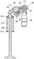
도 1은 본 발명의 제1 실시예에 따른 가변 밸브 리프트 장치의 사시도이다.
도 2는 도 1의 종단면도이다.
도 3은 본 발명의 제1 실시예에 따른 가변 밸브 리프트 장치의 요부 확대도이다.
도 4는 도 3의 종단면도이다.
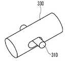
도 5는 본 발명의 제1,2 실시예에 따른 래칭부의 사시도이다.
도 6a는 본 발명의 제1,2 실시예에 따른 언래칭시의 래칭부와 외측 바디의 단면도이다.
도 6b는 본 발명의 제1,2 실시예에 따른 래칭시의 래칭부와 외측 바디의 단면도이다.
도 7은 본 발명의 제2 실시예에 따른 가변 밸브 리프트 장치의 측단면도이다.
도 8은 본 발명의 제2 실시예에 따른 가변 밸브 리프트 장치의 평면도이다.
도 9는 본 발명의 제2 실시예에 따른 캠과 캠축의 단면도이다.
도 10은 종래 가변 밸브 리프트 장치의 사시도이다.
도 11a는 종래 가변 밸브 리프트 장치의 래칭시의 종단면도이다.
도 11b는 종래 가변 밸브 리프트 장치의 언래칭시의 종단면도이다.1 is a perspective view of a variable valve lift apparatus according to a first embodiment of the present invention.
Fig. 2 is a longitudinal sectional view of Fig. 1; Fig.
3 is an enlarged view illustrating main parts of a variable valve lift apparatus according to a first exemplary embodiment of the present invention.
4 is a longitudinal cross-sectional view of FIG. 3.
5 is a perspective view of the latching unit according to the first and second embodiments of the present invention.
6A is a cross-sectional view of the latching portion and the outer body at the time of unlatching according to the first and second embodiments of the present invention.
6B is a cross-sectional view of the latching portion and the outer body at the time of latching according to the first and second embodiments of the present invention.
7 is a side sectional view of a variable valve lift apparatus according to a second embodiment of the present invention.
8 is a plan view of a variable valve lift apparatus according to a second embodiment of the present invention.
9 is a sectional view of a cam and a camshaft according to the second embodiment of the present invention.
10 is a perspective view of a conventional variable valve lift apparatus.
11A is a longitudinal sectional view at the time of latching of a conventional variable valve lift apparatus.
11B is a longitudinal sectional view at the time of unlatching of the conventional variable valve lift apparatus.
이하, 첨부한 도면을 참조하여, 본 발명이 속하는 기술분야에서 통상의 지식을 가진 자가 용이하게 실시할 수 있도록 본 발명의 실시예를 설명한다.Hereinafter, embodiments of the present invention will be described with reference to the accompanying drawings so that those skilled in the art can easily carry out the present invention.
본 발명의 가변 밸브 리프트 장치는 실린더(미도시)의 외측으로 나란히 배열되고, 회전운동하는 서로 다른 캠프로파일을 갖는 하이 캠 및 로우 캠이 각각 외측 바디 또는 내측 바디와 구름접촉하고, 상기 외측 바디와 내측 바디는 로스트 모션 힌지축을 동축으로 하여 결합된다.The variable valve lift apparatus of the present invention is arranged side by side to the outside of the cylinder (not shown), the high cam and the low cam having a different camp profile in rotational motion, respectively, the rolling contact with the outer body or the inner body, the outer body And the inner body are coupled coaxially to the lost motion hinge axis.
먼저, 본 발명에 따른 제1 실시예를 도 1 내지 도 4를 참고하여 설명한다.First, a first embodiment according to the present invention will be described with reference to FIGS. 1 to 4.
도 1은 본 발명의 제1 실시예에 따른 가변 밸브 리프트 장치의 사시도이고, 도 2는 도 1의 종단면도이고, 도 3과 도 4는 본 발명의 제1 실시예에 따른 가변 밸브 리프트 장치의 요부 확대도와 그 단면도이다.1 is a perspective view of a variable valve lift apparatus according to a first embodiment of the present invention, FIG. 2 is a longitudinal sectional view of FIG. 1, and FIGS. 3 and 4 are views of a variable valve lift apparatus according to a first embodiment of the present invention. It is enlarged main part and its sectional drawing.
본 발명의 제1 실시예에 따른 가변 밸브 리프트 장치는 외측 바디(100)는 하이 캠(170)에 의해 가압되고, 내측 바디(200)는 로우 캠(160)에 의해 가압된다. 상기 외측 바디(100)와 내측 바디(200)는 로스트 모션 힌지축(110)을 동축으로 하여 회동이 가능한 구조이다. 또한, 상기 내측 바디(200)의 전단에는 밸브부재(400)가 설치되어 있어 상기 내측 바디(200)의 회동 운동에 의해 상기 밸브부재(400)를 가압하게 되고, 내측 바디(200)의 후단 하부는 힌지부재(150)와 힌지 결합한다. 상기의 밸브부재(400)에는 상단에 밸브 스템 엔드(420)가 형성되고 중간부에는 밸브 스프링 받침(410)이 형성되어 있으며, 그 사이에는 밸브 스프링(430)이 있어 상기 밸브 스프링(430)에 의해 밸브부재(400)가 승하강한다. 또한, 상기 외측 바디(100)는 내측 바디(200)의 하부에서 "∪"형상의 크로스바(180)가 형성되어 상기 내측 바디(200)를 받치고 있는 형상이다. 이 때, 래칭시에는 상기 내측 바디(200) 내에 삽입되어 있던 래칭부(300)가 외부로 돌출되면서 상기 내측 바디(200)와 래칭부(300)의 사이에 외측 바디(100)가 끼워지게 되어, 상기 외측 바디(100)의 움직임에 내측 바디(200)의 움직임도 종속되어, 상기 외측 바디(100)의 승하강에 따라 내측 바디(200)도 함께 승하강할 수 있는 구조로 되어 있다.In the variable valve lift apparatus according to the first embodiment of the present invention, the
그리고, 상기 내측 바디(200)의 내부에는 래칭부(300)가 삽입된다. 상기 래칭부(300)는 오일의 선택적 공급에 따라 이동하여 외측 바디(100)와 내측 바디(200)를 래칭시킨다. 이 때, 래칭은 외측 바디(100)의 전단 하단부가 상기 래칭부(300)를 가압함으로써 상기 래칭부(300)가 삽입되는 내측 바디(200)를 동시에 가압하게 된다. 이는 도 4에 도시되어 있다.In addition, a
이 때, 상기 래칭부(300)는 밸브부재(400)와 힌지부재(150)의 가운데에 위치하고, 보다 바람직하게는 캠축의 직하방에 위치하는 것이 좋다. 이를 위해 래칭부(300)가 내측 바디(200)의 내부에 삽입되어야 한다. 이는 로스트 모션 힌지축(110)으로부터 캠축까지의 거리를 짧게 하여 관성모멘트를 줄이기 위함이다.At this time, the
반면, 언래칭시에는 상기 래칭부(300)가 원래상태로 복귀하면서 래칭을 해제한다. 언래칭시에는 외측 바디(100)가 로스트 모션을 하게 되는데 이는 상기 로스트 모션 힌지축(110)에 결합된 로스트 모션 스프링(120)에 의해 수행된다.On the other hand, when unlatching, the
상기 래칭부(300)는 중공체로 된 원통형의 래칭핀(330)과, 상기 래칭핀(300)의 내부에 삽입되어 오일의 공급에 따라 선택적으로 압축 또는 이완을 하는 리턴 스프링(320)과, 상기 리턴 스프링(320)과 함께 상기 래칭핀(330)의 이동을 제한하는 리턴 스프링 지지핀(310) 및 상기 리턴 스프링(320)과 접촉하고 공급되는 오일을 차단하는 마개(370)로 구성된다.The latching
도 5는 상기 래칭부(300)의 사시도인데, 상기 리턴 스프링 지지핀(310)은 내측 바디(200)에 삽입 고정되어 있는 반면, 래칭핀(330)이 리턴 스프링 지지핀(310)을 기준으로 하여 좌우로 움직인다.5 is a perspective view of the
본 발명에 따른 제2 실시예는 도 7 내지 도 9에 도시하였다.A second embodiment according to the present invention is shown in Figs.
도 7은 본 발명의 제2 실시예에 따른 가변 밸브 리프트 장치의 단면도인데, 이에 의하면 상기 제1 실시예와는 달리 외측 바디(500)의 전단부가 밸브부재(400)와 접촉하고 외측 바디(500)의 후단부는 힌지부재(150)와 힌지결합한다. 또한, 본 발명의 제1 실시예와는 달리 로우 캠(520)이 내측 바디(600)와 접촉하고, 하이 캠(510)이 외측 바디(500)와 접촉한다. 본 발명의 제2 실시예에 따른 가변 밸브 리프트 장치의 캠축(524)과 로우 캠(520) 및 하이 캠(510)의 결합관계를 도 9에 나타내었다.7 is a cross-sectional view of the variable valve lift apparatus according to the second embodiment of the present invention, whereby the front end portion of the
그 외에는 상기 제1 실시예에서와 같다. 즉, 제2 실시예에서도 래칭부(300)는 내측 바디(600)의 내부에 삽입되어 있으며, 래칭부(300)의 구성 역시 래칭핀(330), 리턴 스프링(320), 리턴 스프링 지지핀(310) 및 마개(370)로 구성된다.Otherwise, the same as in the first embodiment. That is, in the second embodiment, the latching
이 때, 상기 제1 실시예에서와 같이 상기 래칭부(300)는 밸브부재(400)와 힌지부재(150)의 가운데에 위치하고, 캠축의 직하방에 위치하는 것이 바람직하다. 이를 위해 래칭부(300)가 내측 바디(600)에 삽입되어야 한다. 이는 로스트 모션 힌지축(550)으로부터 캠축까지의 거리를 짧게 하여 관성모멘트를 줄이기 위함이다.At this time, as in the first embodiment, the latching
이하에서는 본 발명의 제1 실시예와 제2 실시예의 공통부분인 래칭부(300)의 작동과정을 보다 상세하게 설명한다.Hereinafter, an operation process of the
도 6b는 제1 실시예에 따른 래칭시의 래칭부(300)와 외측 바디(100)의 결합관계를 도시한 것인데, 오일챔버(360)에 있던 오일이 오일 공급통로(350)을 통해 래칭핀(330)의 내부로 유입되면 유압이 형성되어 래칭핀(330)을 밀어내게 된다. 이 때, 래칭핀(330)은 리턴 스프링 지지핀(310)에 대항하여 리턴 스프링(320)을 압축하게 된다.6B illustrates a coupling relationship between the latching
즉, 리턴 스프링 지지핀(310)은 움직이지 않고 래칭핀(330)만이 도 6b의 화살표 방향으로 움직이게 된다. 이렇게 하여 래칭핀(330)이 래칭부 결합홈(530)으로 이동하게 되고(도 8 참조), 구동캠이 작동할 때 외측 바디(100)가 래칭핀(330)을 가압하게 된다. 이에 따라 래칭핀(330)이 삽입되어 있는 내측 바디(200)도 함께 하강하게 된다. 이렇게 함으로써 래칭시 모드 즉, 하이 리프트가 수행된다.That is, the return
이에 반해 언래칭시에는 도 6a에 도시된 바와 같이, 래칭핀(330)의 내부에 있던 오일이 외부로 배출된다. 이에 따라 압축되었던 리턴 스프링(320)이 이완된다. 상기 리턴 스프링(320)의 이완에 따라 래칭핀(330)이 원래상태로 복귀한다. 결국, 래칭핀(330)이 내측 바디(200)의 내부에 삽입됨으로써 외측 바디(100)가 하강 운동을 하더라도 내측 바디(200)에는 아무런 영향을 미치지 않는다. 즉, 외측 바디(100)는 로스트 모션을 하게 된다. 이렇게 함으로써 로우 리프트가 완성된다.On the other hand, when unlatching, as shown in FIG. 6A, oil inside the latching
제2 실시예에서도 래칭 모드와 언래칭 모드시에는 상기와 같이 내측 바디(600)에 삽입되어 있던 래칭부(300)의 이동에 의해 외측 바디(500)와 선택적으로 래칭된다.Also in the second embodiment, in the latching mode and the unlatching mode, the
이하에서는 첨부된 도면을 참조하여 제1 실시예의 작동 과정을 설명하기로 한다.Hereinafter, an operation process of the first embodiment will be described with reference to the accompanying drawings.
상기 도 1과 도 2에 도시된 바와 같이, 외측 바디(100)와 내측 바디(200)는 로스트 모션 힌지축(110)에 의해 힌지결합되어 있어, 상기 로스트 모션 힌지축(110)을 중심축으로 하여 상기 외측 바디(100)와 내측 바디(200)의 전단이 회동운동을 하게 된다. 이 때, 내측 바디(200)는 밸브부재(400)를 가압하여 밸브의 흡배기를 조절한다. 또한, 하이 캠(170)은 외측 바디(100)를 가압하고, 로우 캠(160)은 내측 바디(200)를 가압한다.As shown in FIGS. 1 and 2, the
외측 바디(100)와 내측 바디(200)의 래칭시는 도 6b에 도시된 바와 같이, 오일 공급통로(350)를 통해 오일이 공급되면서 형성된 유압에 의해 래칭핀(330)이 리턴 스프링(320)을 압축하면서 래칭핀(330)을 외부로 노출시키게 된다. 이 때, 리턴 스프링 지지핀(310)은 고정되어 있다. 이 상태에서 외측 바디(100)가 하강하면 상기 외측 바디(100)가 래칭핀(330)을 누르게 된다. 결국, 래칭핀(330)이 삽입되어 있는 내측 바디(100)도 함께 하강하게 된다. 이렇게 하여 래칭 모드인 하이 리프트가 완성된다. 이 때는 로우 캠(160)과 내측 바디(200)는 서로 접촉하지 않게 된다.When latching the
이에 반해 외측 바디(100)와 내측 바디(200)의 언래칭시는 도 6a에 도시된 바와 같이, 래칭핀(330)의 내부에 있던 오일이 외부로 배출됨으로써 시작된다. 오일이 외부로 배출됨에 따라 리턴 스프링(320)을 압축하던 유압이 해제되고, 이에 따라 리턴 스프링(320)이 이완된다. 즉, 리턴 스프링(320)의 복원력에 의해 리턴 스프링 지지핀(310)을 지지점으로 하여 래칭핀(330)을 원래 상태로 복귀시킨다. 결국, 래칭핀(330)은 다시 내측 바디(200)의 내부로 삽입되어 외측 바디(100)와 내측 바디(200)는 언래칭된다. 이렇게 하여 언래칭 모드인 로우 리프트가 완성된다. 이 때, 상기 외측 바디(100)는 로스트 모션을 하게 되는데, 이는 로스트 모션 스프링(120)에 의해 수행된다.On the contrary, when the
이하에서는 본 발명의 제2 실시예의 작동과정에 대하여 설명한다. 다만, 제2 실시예에서도 래칭부(300)는 제1 실시예에서와 동일하다.Hereinafter will be described the operation of the second embodiment of the present invention. However, in the second embodiment, the latching
제2 실시예에 대해서는 도 7 내지 도 10에 도시되어 있다. 본 발명에 따른 제2 실시예가 제1 실시예와 다른 점은 외측 바디(500)가 밸브부재(400)를 가압하게 되는 점이다. 즉, 제1 실시예에서는 내측 바디(200)가 밸브부재(400)를 가압하므로 밸브부재(400)를 직접 가압하지 않는 외측 바디(100)가 로스트 모션을 하는 반면, 제2 실시예에서는 밸브부재(400)와 직접 접촉하지 않는 내측 바디(600)가 로스트 모션을 하게 된다. 이 때의 로스트 모션은 로스트 모션 스프링(540)에 의해 수행된다.A second embodiment is shown in FIGS. 7 to 10. The second embodiment according to the present invention differs from the first embodiment in that the
또한, 로우 캠(520)이 외측 바디(500)를 가압하게 되고, 하이 캠(510)이 내측 바디(600)을 가압하게 된다.Also, the
제2 실시예의 래칭시의 작동과정을 보다 구체적으로 살펴보면, 오일 공급통로(550)를 통해 오일이 래칭핀(300)에 공급되면서 형성된 유압에 의해 상기 래칭핀(300)이 리턴 스프링(320)을 압축하면서 래칭부 결합홈(530)으로 삽입된다.(도 8 참조) 이에 의해 외측 바디(500)와 내측 바디(600)가 결합된다. 상기 외측 바디(500)와 내측 바디(600)가 결합된 상태에서 하이 캠(510)이 회전하면서 내측 바디(600)를 가압한다. 결국, 도 7에 도시된 바와 같이 외측 바디(500)가 회동운동하면서 점선으로 그려진 외측 바디(502)와 같은 모습을 나타낸다. 이렇게 하여 내측 바디(600)와 결합된 외측 바디(500)가 밸브부재(400)를 가압하면서 하이 리프트를 완성한다.Looking at the operation of the latching in the second embodiment in more detail, the latching
제2 실시예의 언래칭시에는 오일 공급통로(550)에서 오일이 외부로 배출되면서 리턴 스프링(320)이 이완된다. 상기 리턴 스프링(320)의 이완 동작에 의하여 래칭핀(330)이 원래상태로 복귀된다. 이에 의해 외측 바디(500)와 내측 바디(600)의 결합이 해제된다. 따라서, 상기 외측 바디(500)와 내측 바디(600)는 독립적으로 운동하게 되고, 하이 캠(510)이 내측 바디(600)을 가압하지만 상기 내측 바디(600)는 외측 바디(500)에 아무런 영향을 미치지 않아 내측 바디(600)는 로스트 모션을 하게 된다. 이렇게 하여 로우 리프트가 실행된다.In the unlatching of the second embodiment, the
상기와 같이 래칭부(300)에 의해 외측 바디(100,500)와 내측 바디(200,600)를 선택적으로 결합하면서, 로스트 모션 힌지축(110)과 내측 바디(100) 또는 외측 바디(500)와 힌지부재(150)와의 힌지점을 캠축을 기준으로 하여 동일한 방향에 위치시킴으로써 관성모멘트를 줄여 동특성을 향상시킬 수 있다.As described above, the
본 발명에서는 상기의 내측 바디(100) 또는 외측 바디(500)와 힌지부재(150)와의 힌지점을 가변 밸브 리프트 장치의 힌지점으로 칭하기로 한다.In the present invention, the hinge point of the
10: 외측 바디 20: 내측 바디
30: 래칭기구 40: 로스트 모션 힌지축
50: 로스트 모션 스프링 60: 가변 밸브 리프트 힌지축
100: 외측 바디 110: 로스트 모션 힌지축
120: 로스트 모션 스프링 140: 롤러
150: 힌지부재(HLA) 160: 로우 캠
170: 하이 캠 180: 크로스바
200: 내측 바디 300: 래칭부 310: 리턴 스프링 지지핀 320: 리턴 스프링
330: 래칭핀 350: 유압 공급통로
360: 오일챔버 370: 마개
400: 밸브부재 410: 밸브 스프링 받침
420: 밸브 스템 엔드 430: 밸브 스프링
500: 외측 바디 502: 하이 리프트시의 외측 바디
510: 하이 캠 520: 로우 캠
524: 캠축 530: 래칭부 결합홈
540: 로스트 모션 스프링 542: 로스트 모션 힌지축
550: 오일 공급통로 600: 내측 바디10: outer body 20: inner body
30: latching mechanism 40: lost motion hinge axis
50: lost motion spring 60: variable valve lift hinge shaft
100: outer body 110: lost motion hinge axis
120: lost motion spring 140: roller
150: hinge member (HLA) 160: low cam
170: high cam 180: crossbar
200: inner body 300: latching portion 310: return spring support pin 320: return spring
330: latching pin 350: hydraulic supply passage
360: oil chamber 370: stopper
400: valve member 410: valve spring support
420: valve stem end 430: valve spring
500: outer body 502: outer body at high lift
510: high cam 520: low cam
524: camshaft 530: latching engaging groove
540: lost motion spring 542: lost motion hinge axis
550: oil supply passage 600: inner body
Claims (8)
Translated fromKorean캠축에 나란히 고정되는 하이 캠 및 로우 캠;
상기 하이 캠의 회전에 의해 가압되고, 전단은 아래에 크로스바가 있는 외측 바디;
상기 로우 캠의 회전에 의해 가압되고, 상기 외측 바디의 내부에 설치되며, 전단은 상기 외측 바디보다 돌출되고, 전단 하측에는 밸브부재가 설치되며, 후단부 상측은 상기 외측 바디의 후단과 동축상으로 로스트 모션 힌지축에 힌지결합되고, 후단부 하측은 힌지부재와 피봇결합하는 내측 바디;
상기 내측 바디 내에 삽입되어 상기 외측 바디의 크로스바와의 선택적 결합에 의하여 상기 외측 바디 전단의 움직임에 내측 바디의 움직임이 종속되도록 하는 래칭부;
로 구성되되,
상기 로스트 모션 힌지축은 캠축을 기준으로 상기 내측 바디와 힌지부재의 힌지점과 같은 방향에 설치되고, 상기 래칭부는 상기 캠의 직하방에 배치되는 것을 특징으로 하는 가변 밸브 리프트 장치.In the variable valve lift apparatus,
A high cam and a low cam fixed to the camshaft side by side;
An outer body pressurized by rotation of the high cam, the front end having a crossbar below;
Pressed by the rotation of the low cam, is installed inside the outer body, the front end is projected than the outer body, the lower end of the valve member is installed, the rear end upper side is coaxial with the rear end of the outer body An inner body hinged to the lost motion hinge axis, the rear end being pivotally coupled to the hinge member;
A latching portion inserted into the inner body to allow the movement of the inner body to be dependent on the movement of the front end of the outer body by selective engagement with the crossbar of the outer body;
Consist of
The lost motion hinge axis is installed in the same direction as the hinge point of the inner body and the hinge member relative to the cam axis, the latching portion is variable valve lift apparatus, characterized in that disposed directly below the cam.
상기 래칭부는,
내부는 중공체인 원통형의 래칭핀과,
상기 래칭핀의 내부에 삽입되어 오일의 공급에 의해 선택적으로 압축 또는 이완하여 상기 래칭핀을 선택적으로 이동시키는 리턴 스프링을 포함하여 구성되는 것을 특징으로 하는 가변 밸브 리프트 장치.The method of claim 1,
The latching unit,
Inside is a hollow cylindrical latching pin,
And a return spring inserted into the latching pin and selectively compressed or relaxed by supply of oil to selectively move the latching pin.
상기 래칭부는,
상기 리턴 스프링의 끝단에 위치하고, 내측 바디에 삽입 고정되어 래칭핀의 이동을 제한하는 리턴 스프링 지지핀을 더 포함하는 것을 특징으로 하는 가변 밸브 리프트 장치.The method of claim 2,
The latching unit,
Located at the end of the return spring, the variable valve lift apparatus further comprises a return spring support pin inserted into the inner body to limit the movement of the latching pin.
상기 래칭부는,
상기 내측 바디의 후단 하부와 연결되는 힌지부재와 밸브부재 중앙에 위치하는 것을 특징으로 하는 가변 밸브 리프트 장치.4. The method according to any one of claims 1 to 3,
The latching unit,
Variable valve lift apparatus, characterized in that located in the center of the hinge member and the valve member connected to the lower rear end of the inner body.
캠축에 나란히 고정되는 하이 캠 및 로우 캠;
상기 로우 캠의 회전에 의해 가압되고, 전단측에는 밸브부재가 설치되며, 후단부 상측은 로스트 모션 힌지축에 결합되며, 후단부 하측은 힌지부재와 피봇결합하는 외측 바디;
상기 외측 바디의 내부에 삽입되고, 후단부는 상기 외측 바디와 동축상으로 로스트 모션 힌지축에 힌지 결합되는 내측 바디;
상기 내측 바디의 전단측에 삽입되어 외측 바디내로의 선택적 이동에 의하여 상기 외측 바디와 내측 바디를 선택적으로 결합시키는 래칭부;
로 구성되되,
상기 로스트 모션 힌지축은 캠축을 기준으로 상기 외측 바디와 힌지부재의 힌지점과 같은 방향에 설치되는 것을 특징으로 하는 가변 밸브 리프트 장치.In the variable valve lift apparatus,
A high cam and a low cam fixed to the camshaft side by side;
An outer body pressurized by the rotation of the low cam, a valve member installed at a front end, an upper end of the rear end coupled to a lost motion hinge shaft, and a lower end of the rear end pivoted to the hinge member;
An inner body inserted into the outer body and having a rear end hinged to a lost motion hinge axis coaxially with the outer body;
A latching portion inserted into the front end side of the inner body to selectively couple the outer body and the inner body by selective movement into the outer body;
Consist of
The lost motion hinge shaft is a variable valve lift apparatus, characterized in that installed in the same direction as the hinge point of the outer body and the hinge member relative to the cam axis.
상기 래칭부는,
상기 로스트 모션 힌지축과 수직으로 형성되고, 내부는 중공체인 원통형의 래칭핀과,
상기 래칭핀의 내부에 삽입되어 오일의 공급에 의해 선택적으로 압축 또는 이완하여 상기 래칭핀을 이동시키는 리턴 스프링을 포함하여 구성되는 것을 특징으로 하는 가변 밸브 리프트 장치.The method of claim 5,
The latching unit,
A cylindrical latching pin formed perpendicular to the lost motion hinge axis and having a hollow body;
And a return spring inserted into the latching pin to selectively compress or relax by supplying oil to move the latching pin.
상기 래칭부는,
상기 리턴 스프링의 끝단에 위치하고, 내측 바디에 삽입 고정되어 래칭핀의 이동을 제한하는 리턴 스프링 지지핀을 더 포함하는 것을 특징으로 하는 가변 밸브 리프트 장치.The method according to claim 6,
The latching unit,
Located at the end of the return spring, the variable valve lift apparatus further comprises a return spring support pin inserted into the inner body to limit the movement of the latching pin.
상기 래칭부는,
상기 외측 바디의 후단 하부와 연결되는 힌지부재와 밸브부재 중앙에 위치하는 것을 특징으로 하는 가변 밸브 리프트 장치.8. The method according to any one of claims 5 to 7,
The latching unit,
Variable valve lift apparatus, characterized in that located in the center of the hinge member and the valve member connected to the lower rear end of the outer body.
Priority Applications (4)
| Application Number | Priority Date | Filing Date | Title |
|---|---|---|---|
| KR1020100103359AKR101209737B1 (en) | 2010-10-22 | 2010-10-22 | Variable valve lift system |
| US13/189,713US8464677B2 (en) | 2010-10-22 | 2011-07-25 | Variable valve lift apparatus |
| DE102011052151ADE102011052151A1 (en) | 2010-10-22 | 2011-07-26 | Variable valve lift |
| CN201110212988.4ACN102454445B (en) | 2010-10-22 | 2011-07-26 | Variable air valve lift apparatus |
Applications Claiming Priority (1)
| Application Number | Priority Date | Filing Date | Title |
|---|---|---|---|
| KR1020100103359AKR101209737B1 (en) | 2010-10-22 | 2010-10-22 | Variable valve lift system |
Publications (2)
| Publication Number | Publication Date |
|---|---|
| KR20120041937A KR20120041937A (en) | 2012-05-03 |
| KR101209737B1true KR101209737B1 (en) | 2012-12-07 |
Family
ID=45923322
Family Applications (1)
| Application Number | Title | Priority Date | Filing Date |
|---|---|---|---|
| KR1020100103359AExpired - Fee RelatedKR101209737B1 (en) | 2010-10-22 | 2010-10-22 | Variable valve lift system |
Country Status (4)
| Country | Link |
|---|---|
| US (1) | US8464677B2 (en) |
| KR (1) | KR101209737B1 (en) |
| CN (1) | CN102454445B (en) |
| DE (1) | DE102011052151A1 (en) |
Cited By (1)
| Publication number | Priority date | Publication date | Assignee | Title |
|---|---|---|---|---|
| US10167750B2 (en) | 2016-08-17 | 2019-01-01 | Hyundai Motor Company | Variable valve duration apparatus |
Families Citing this family (26)
| Publication number | Priority date | Publication date | Assignee | Title |
|---|---|---|---|---|
| WO2015134466A1 (en) | 2014-03-03 | 2015-09-11 | Eaton Corporation | Valve actuating device and method of making same |
| US20190309663A9 (en) | 2008-07-22 | 2019-10-10 | Eaton Corporation | Development of a switching roller finger follower for cylinder deactivation in internal combustion engines |
| US9284859B2 (en) | 2010-03-19 | 2016-03-15 | Eaton Corporation | Systems, methods, and devices for valve stem position sensing |
| US9016252B2 (en) | 2008-07-22 | 2015-04-28 | Eaton Corporation | System to diagnose variable valve actuation malfunctions by monitoring fluid pressure in a hydraulic lash adjuster gallery |
| US8985074B2 (en) | 2010-03-19 | 2015-03-24 | Eaton Corporation | Sensing and control of a variable valve actuation system |
| US9581058B2 (en) | 2010-08-13 | 2017-02-28 | Eaton Corporation | Development of a switching roller finger follower for cylinder deactivation in internal combustion engines |
| US9228454B2 (en) | 2010-03-19 | 2016-01-05 | Eaton Coporation | Systems, methods and devices for rocker arm position sensing |
| US9708942B2 (en) | 2010-03-19 | 2017-07-18 | Eaton Corporation | Rocker arm assembly and components therefor |
| US9938865B2 (en) | 2008-07-22 | 2018-04-10 | Eaton Corporation | Development of a switching roller finger follower for cylinder deactivation in internal combustion engines |
| US9291075B2 (en) | 2008-07-22 | 2016-03-22 | Eaton Corporation | System to diagnose variable valve actuation malfunctions by monitoring fluid pressure in a control gallery |
| US10415439B2 (en) | 2008-07-22 | 2019-09-17 | Eaton Intelligent Power Limited | Development of a switching roller finger follower for cylinder deactivation in internal combustion engines |
| US11181013B2 (en) | 2009-07-22 | 2021-11-23 | Eaton Intelligent Power Limited | Cylinder head arrangement for variable valve actuation rocker arm assemblies |
| US10087790B2 (en) | 2009-07-22 | 2018-10-02 | Eaton Corporation | Cylinder head arrangement for variable valve actuation rocker arm assemblies |
| US9194261B2 (en) | 2011-03-18 | 2015-11-24 | Eaton Corporation | Custom VVA rocker arms for left hand and right hand orientations |
| US9874122B2 (en) | 2010-03-19 | 2018-01-23 | Eaton Corporation | Rocker assembly having improved durability |
| US9885258B2 (en) | 2010-03-19 | 2018-02-06 | Eaton Corporation | Latch interface for a valve actuating device |
| KR101145638B1 (en)* | 2010-05-06 | 2012-07-11 | 현대자동차주식회사 | Variable valve lift apparatus |
| USD750670S1 (en)* | 2013-02-22 | 2016-03-01 | Eaton Corporation | Rocker arm |
| US9464544B2 (en)* | 2014-06-19 | 2016-10-11 | Motonic Corporation | Variable valve lift apparatus of engine |
| KR101566756B1 (en)* | 2014-09-05 | 2015-11-06 | 현대자동차 주식회사 | Variable valve lift appratus |
| CN104373170A (en)* | 2014-09-11 | 2015-02-25 | 绵阳富临精工机械股份有限公司 | Valve stroke control compression bar |
| KR20160057761A (en)* | 2014-11-14 | 2016-05-24 | 현대자동차주식회사 | Variable valve lift appratus |
| US10006322B2 (en) | 2016-04-26 | 2018-06-26 | Hyundai Motor Company | Variable valve lift apparatus |
| DE102016220859A1 (en)* | 2016-10-24 | 2017-09-07 | Schaeffler Technologies AG & Co. KG | Module of a variable valve train of an internal combustion engine |
| KR102644379B1 (en)* | 2018-11-20 | 2024-03-07 | 현대자동차주식회사 | Mechanical electro variable valve device, control device of variable valve device, variable valve system comprising the same and control method thereof |
| AT524194B1 (en)* | 2020-08-24 | 2022-12-15 | Avl List Gmbh | valve actuator |
Family Cites Families (9)
| Publication number | Priority date | Publication date | Assignee | Title |
|---|---|---|---|---|
| DE102005053596A1 (en)* | 2005-11-10 | 2007-05-16 | Schaeffler Kg | Switchable drag lever of a valve train of an internal combustion engine |
| KR101220346B1 (en) | 2006-09-08 | 2013-01-09 | 현대자동차주식회사 | Variable valve lift apparatus of engine for vehicles |
| KR101231383B1 (en)* | 2006-12-06 | 2013-02-07 | 현대자동차주식회사 | Variable valve device of latching shaft rotating type for engine |
| KR20090043283A (en) | 2007-10-29 | 2009-05-06 | 현대자동차주식회사 | Two-stage variable valve drive system of automobile roller swing arm type |
| KR100980866B1 (en)* | 2007-12-14 | 2010-09-10 | 현대자동차주식회사 | Variable valve lift device |
| US8726862B2 (en)* | 2010-03-19 | 2014-05-20 | Eaton Corporation | Switching rocker arm |
| JP5276486B2 (en) | 2009-03-13 | 2013-08-28 | 富士重工業株式会社 | drill |
| DE102010019071A1 (en)* | 2009-06-01 | 2011-01-13 | Schaeffler Technologies Gmbh & Co. Kg | Switchable drag lever |
| KR101090798B1 (en)* | 2009-06-04 | 2011-12-08 | 현대자동차주식회사 | Variable tappet |
- 2010
- 2010-10-22KRKR1020100103359Apatent/KR101209737B1/ennot_activeExpired - Fee Related
- 2011
- 2011-07-25USUS13/189,713patent/US8464677B2/ennot_activeExpired - Fee Related
- 2011-07-26CNCN201110212988.4Apatent/CN102454445B/ennot_activeExpired - Fee Related
- 2011-07-26DEDE102011052151Apatent/DE102011052151A1/ennot_activeWithdrawn
Cited By (1)
| Publication number | Priority date | Publication date | Assignee | Title |
|---|---|---|---|---|
| US10167750B2 (en) | 2016-08-17 | 2019-01-01 | Hyundai Motor Company | Variable valve duration apparatus |
Also Published As
| Publication number | Publication date |
|---|---|
| DE102011052151A1 (en) | 2012-04-26 |
| US20120097878A1 (en) | 2012-04-26 |
| CN102454445B (en) | 2015-08-05 |
| KR20120041937A (en) | 2012-05-03 |
| CN102454445A (en) | 2012-05-16 |
| US8464677B2 (en) | 2013-06-18 |
Similar Documents
| Publication | Publication Date | Title |
|---|---|---|
| KR101209737B1 (en) | Variable valve lift system | |
| US8813719B2 (en) | Internal combustion piston engine with a compression relief engine brake | |
| US9745873B2 (en) | Multiple variable valve lift apparatus | |
| CN108699926A (en) | Actuation means | |
| KR101209740B1 (en) | Engine that is equipped with variable valve device | |
| KR101198799B1 (en) | Engine that is equipped with variable valve device | |
| KR101209743B1 (en) | Variable valve lift apparatus | |
| KR102335529B1 (en) | Engine brake device | |
| KR101370717B1 (en) | 3 point supporting dual cylinder de-activation device | |
| KR101209726B1 (en) | Variable valve lift apparatus | |
| KR101368566B1 (en) | 4 point supporting dual cylinder de-activation device | |
| KR101234653B1 (en) | Varible vavle lift apparatus | |
| KR101274237B1 (en) | Variable tappet and variable valve lift apparatus provided with the same | |
| CN106121765A (en) | A kind of air valve bridge assembly and engine exhaust and brake system | |
| KR101145638B1 (en) | Variable valve lift apparatus | |
| KR101114388B1 (en) | Engine brake system with rocker arm | |
| KR101209736B1 (en) | Variable valve lift apparatus | |
| KR101272942B1 (en) | Variable valve system | |
| KR101225883B1 (en) | A variable valve operating system | |
| US7255076B2 (en) | Variable valve lift apparatus for vehicle engines | |
| KR100959172B1 (en) | Pneumatic engine with double-sided cam | |
| KR101339276B1 (en) | Variable valve lift device | |
| JP2004084596A (en) | Exhaust valve control device | |
| CN105658917B (en) | The valve mechanism of internal combustion engine | |
| JP6239432B2 (en) | Valve mechanism of internal combustion engine |
Legal Events
| Date | Code | Title | Description |
|---|---|---|---|
| A201 | Request for examination | ||
| PA0109 | Patent application | St.27 status event code:A-0-1-A10-A12-nap-PA0109 | |
| PA0201 | Request for examination | St.27 status event code:A-1-2-D10-D11-exm-PA0201 | |
| PE0902 | Notice of grounds for rejection | St.27 status event code:A-1-2-D10-D21-exm-PE0902 | |
| PG1501 | Laying open of application | St.27 status event code:A-1-1-Q10-Q12-nap-PG1501 | |
| P11-X000 | Amendment of application requested | St.27 status event code:A-2-2-P10-P11-nap-X000 | |
| P13-X000 | Application amended | St.27 status event code:A-2-2-P10-P13-nap-X000 | |
| E701 | Decision to grant or registration of patent right | ||
| PE0701 | Decision of registration | St.27 status event code:A-1-2-D10-D22-exm-PE0701 | |
| GRNT | Written decision to grant | ||
| PR0701 | Registration of establishment | St.27 status event code:A-2-4-F10-F11-exm-PR0701 | |
| PR1002 | Payment of registration fee | St.27 status event code:A-2-2-U10-U11-oth-PR1002 Fee payment year number:1 | |
| PG1601 | Publication of registration | St.27 status event code:A-4-4-Q10-Q13-nap-PG1601 | |
| PN2301 | Change of applicant | St.27 status event code:A-5-5-R10-R13-asn-PN2301 St.27 status event code:A-5-5-R10-R11-asn-PN2301 | |
| PR1001 | Payment of annual fee | St.27 status event code:A-4-4-U10-U11-oth-PR1001 Fee payment year number:4 | |
| R18-X000 | Changes to party contact information recorded | St.27 status event code:A-5-5-R10-R18-oth-X000 | |
| PR1001 | Payment of annual fee | St.27 status event code:A-4-4-U10-U11-oth-PR1001 Fee payment year number:5 | |
| PR1001 | Payment of annual fee | St.27 status event code:A-4-4-U10-U11-oth-PR1001 Fee payment year number:6 | |
| PR1001 | Payment of annual fee | St.27 status event code:A-4-4-U10-U11-oth-PR1001 Fee payment year number:7 | |
| R18-X000 | Changes to party contact information recorded | St.27 status event code:A-5-5-R10-R18-oth-X000 | |
| FPAY | Annual fee payment | Payment date:20191127 Year of fee payment:8 | |
| PR1001 | Payment of annual fee | St.27 status event code:A-4-4-U10-U11-oth-PR1001 Fee payment year number:8 | |
| PR1001 | Payment of annual fee | St.27 status event code:A-4-4-U10-U11-oth-PR1001 Fee payment year number:9 | |
| PR1001 | Payment of annual fee | St.27 status event code:A-4-4-U10-U11-oth-PR1001 Fee payment year number:10 | |
| PR1001 | Payment of annual fee | St.27 status event code:A-4-4-U10-U11-oth-PR1001 Fee payment year number:11 | |
| PC1903 | Unpaid annual fee | St.27 status event code:A-4-4-U10-U13-oth-PC1903 Not in force date:20231204 Payment event data comment text:Termination Category : DEFAULT_OF_REGISTRATION_FEE | |
| PC1903 | Unpaid annual fee | St.27 status event code:N-4-6-H10-H13-oth-PC1903 Ip right cessation event data comment text:Termination Category : DEFAULT_OF_REGISTRATION_FEE Not in force date:20231204 |