KR101207389B1 - Device for spinal adjustment - Google Patents
Device for spinal adjustmentDownload PDFInfo
- Publication number
- KR101207389B1 KR101207389B1KR1020120075416AKR20120075416AKR101207389B1KR 101207389 B1KR101207389 B1KR 101207389B1KR 1020120075416 AKR1020120075416 AKR 1020120075416AKR 20120075416 AKR20120075416 AKR 20120075416AKR 101207389 B1KR101207389 B1KR 101207389B1
- Authority
- KR
- South Korea
- Prior art keywords
- contact member
- contact
- chiropractic
- elastic body
- spine
- Prior art date
- Legal status (The legal status is an assumption and is not a legal conclusion. Google has not performed a legal analysis and makes no representation as to the accuracy of the status listed.)
- Active
Links
Images


Classifications
- A—HUMAN NECESSITIES
- A61—MEDICAL OR VETERINARY SCIENCE; HYGIENE
- A61H—PHYSICAL THERAPY APPARATUS, e.g. DEVICES FOR LOCATING OR STIMULATING REFLEX POINTS IN THE BODY; ARTIFICIAL RESPIRATION; MASSAGE; BATHING DEVICES FOR SPECIAL THERAPEUTIC OR HYGIENIC PURPOSES OR SPECIFIC PARTS OF THE BODY
- A61H1/00—Apparatus for passive exercising; Vibrating apparatus; Chiropractic devices, e.g. body impacting devices, external devices for briefly extending or aligning unbroken bones
- A61H1/008—Apparatus for applying pressure or blows almost perpendicular to the body or limb axis, e.g. chiropractic devices for repositioning vertebrae, correcting deformation
- A—HUMAN NECESSITIES
- A61—MEDICAL OR VETERINARY SCIENCE; HYGIENE
- A61F—FILTERS IMPLANTABLE INTO BLOOD VESSELS; PROSTHESES; DEVICES PROVIDING PATENCY TO, OR PREVENTING COLLAPSING OF, TUBULAR STRUCTURES OF THE BODY, e.g. STENTS; ORTHOPAEDIC, NURSING OR CONTRACEPTIVE DEVICES; FOMENTATION; TREATMENT OR PROTECTION OF EYES OR EARS; BANDAGES, DRESSINGS OR ABSORBENT PADS; FIRST-AID KITS
- A61F5/00—Orthopaedic methods or devices for non-surgical treatment of bones or joints; Nursing devices ; Anti-rape devices
- A61F5/01—Orthopaedic devices, e.g. long-term immobilising or pressure directing devices for treating broken or deformed bones such as splints, casts or braces
- A61F5/0102—Orthopaedic devices, e.g. long-term immobilising or pressure directing devices for treating broken or deformed bones such as splints, casts or braces specially adapted for correcting deformities of the limbs or for supporting them; Ortheses, e.g. with articulations
- A—HUMAN NECESSITIES
- A61—MEDICAL OR VETERINARY SCIENCE; HYGIENE
- A61H—PHYSICAL THERAPY APPARATUS, e.g. DEVICES FOR LOCATING OR STIMULATING REFLEX POINTS IN THE BODY; ARTIFICIAL RESPIRATION; MASSAGE; BATHING DEVICES FOR SPECIAL THERAPEUTIC OR HYGIENIC PURPOSES OR SPECIFIC PARTS OF THE BODY
- A61H1/00—Apparatus for passive exercising; Vibrating apparatus; Chiropractic devices, e.g. body impacting devices, external devices for briefly extending or aligning unbroken bones
- A61H1/006—Apparatus for applying pressure or blows for compressive stressing of a part of the skeletal structure, e.g. for preventing or alleviating osteoporosis
- A—HUMAN NECESSITIES
- A61—MEDICAL OR VETERINARY SCIENCE; HYGIENE
- A61H—PHYSICAL THERAPY APPARATUS, e.g. DEVICES FOR LOCATING OR STIMULATING REFLEX POINTS IN THE BODY; ARTIFICIAL RESPIRATION; MASSAGE; BATHING DEVICES FOR SPECIAL THERAPEUTIC OR HYGIENIC PURPOSES OR SPECIFIC PARTS OF THE BODY
- A61H23/00—Percussion or vibration massage, e.g. using supersonic vibration; Suction-vibration massage; Massage with moving diaphragms
- A61H23/006—Percussion or tapping massage
- A—HUMAN NECESSITIES
- A61—MEDICAL OR VETERINARY SCIENCE; HYGIENE
- A61H—PHYSICAL THERAPY APPARATUS, e.g. DEVICES FOR LOCATING OR STIMULATING REFLEX POINTS IN THE BODY; ARTIFICIAL RESPIRATION; MASSAGE; BATHING DEVICES FOR SPECIAL THERAPEUTIC OR HYGIENIC PURPOSES OR SPECIFIC PARTS OF THE BODY
- A61H23/00—Percussion or vibration massage, e.g. using supersonic vibration; Suction-vibration massage; Massage with moving diaphragms
- A61H23/06—Hand percussion, i.e. Hand driven
Landscapes
- Health & Medical Sciences (AREA)
- Animal Behavior & Ethology (AREA)
- Veterinary Medicine (AREA)
- Public Health (AREA)
- General Health & Medical Sciences (AREA)
- Life Sciences & Earth Sciences (AREA)
- Rehabilitation Therapy (AREA)
- Physical Education & Sports Medicine (AREA)
- Pain & Pain Management (AREA)
- Epidemiology (AREA)
- Orthopedic Medicine & Surgery (AREA)
- Rheumatology (AREA)
- Nursing (AREA)
- Engineering & Computer Science (AREA)
- Biomedical Technology (AREA)
- Heart & Thoracic Surgery (AREA)
- Vascular Medicine (AREA)
- Orthopedics, Nursing, And Contraception (AREA)
Abstract
Translated fromKoreanDescription
Translated fromKorean본 발명은 고무망치를 통해 전달되는 가격의 힘 중 일부가 탄성체를 압착하는데 사용되어 완충됨으로써, 척추교정시술 중 타격하는 힘에 의해 발생되는 통증의 세기를 반감시켜주고, 척추의 구분에 따라 척추에 선별 접촉되는 다양한 형상 및 크기를 갖는 접촉부재들을 교체하여 사용할 수 있는 척추교정기구에 관한 것이다.
According to the present invention, a part of the price force transmitted through the rubber hammer is used to compress the elastic body to cushion the elastic body, thereby halving the intensity of pain caused by the striking force during the orthodontic surgery, and according to the classification of the spine. It relates to a chiropractic device that can be used to replace the contact members having a variety of shapes and sizes to be in selective contact.
일반적으로, 척추는 신체를 지지하는 부분으로서, 통상 24개의 뼈로 구성되며, 인접한 뼈의 사이에는 디스크가 구비되고, 뼈의 중앙으로는 신경이 지나가도록 구성된다.In general, the spine is a part that supports the body, and usually consists of 24 bones, a disk is provided between adjacent bones, and the nerve is passed through the center of the bone.
특히, 척추를 이루는 24개의 뼈는 목뼈에 해당되는 경추, 등뼈에 해당하는 흉추, 허리뼈에 해당하는 요추, 엉치뼈에 해당하는 천추 및 꼬리뼈에 해당하는 미추로 이루어지며, 척추의 치료 또는 교정을 위해서는 척추돌기를 가압함으로써, 잘못된 척추의 위치가 올바른 위치에 이르게 해야 한다.In particular, the 24 bones that make up the spine are composed of cervical spine corresponding to the neck bone, thoracic spine corresponding to the spine, lumbar spine corresponding to the lumbar spine, sacral spine corresponding to the sacrum, and caudal spine corresponding to the tailbone. In order to press the spine, the wrong spine must be brought to the correct position.
즉 극돌기와 같은 척추돌기를 밀거나 가격하는 등의 가압을 통하여 척추의 위치를 제대로 잡게 되는데, 통상적으로 이러한 시술은 환자의 등에 수건을 대고 그 상부에서 손이나 발을 이용하여 시술을 한다.That is, the position of the spine is properly secured by pushing or striking the spinal processes such as spinous processes. In general, such a procedure is performed by using a hand or a foot on the upper part of a patient with a towel.
하지만, 이러한 경우, 수건이 환자의 등을 덮고 있어 시술이 이루어져야 할 대상돌기의 정확한 위치를 파악하기가 어려운 문제점이 있었는데 선등록된 척추교정구(등록실용신안 제20-0458297호)에 의해 해소되었다.In this case, however, the towel covered the patient's back, making it difficult to determine the exact location of the object to be treated, which was solved by the pre-registered spinal cord (Registration Utility Model No. 20-0458297). .
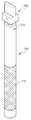
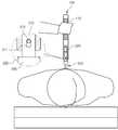
도 1은 선등록된 종래의 척추교정구를 나타낸 사시도이고, 도 2 및 도 3은 종래의 척추교정구를 이용하여 척추교정시술을 수행하는 것을 나타낸 도면이다.1 is a perspective view showing a pre-registered conventional chiropractic, Figure 2 and 3 is a view showing performing a chiropractic using a conventional chiropractic.
도시된 바와 같이, 종래의 척추교정구는 원통형상을 갖는 원통 몸체(10)에 실리콘이 도포되어 이루어진 외피(20)로 이루어지되, 그 도포된 외피(20) 중 원통 몸체(10)의 길이방향을 따라 일부를 절개하여 원통 몸체(10)가 외부에 노출되게 함으로써, 그 노출된 원통 몸체(10)의 표면이 척추교정시술을 받는 환자의 환부에 가격하기 위한 면인 타격면(11)으로 이용되는 구조로 이루어져 있다.As shown, the conventional spinal braces are made of a
또한, 절개되지 않아 온전하게 외피(20)가 도포된 원통 몸체(10)의 부분은 척추교정시술 시 시술자가 잡는 파지영역(12)으로 이용된다.In addition, the portion of the
이와 같은, 종래의 척추교정구를 이용하여 척추교정시술 과정을 설명하면 다음과 같다.As described above, the process of chiropractic treatment using a conventional chiropractic tool is as follows.
먼저, 시술자는 바닥에 엎드린 환자의 등 쪽 척추 부위 중 척추교정을 수행할 등 쪽 척추 부위에 원통 몸체(10)의 타격면(11)이 상부에 위치되게 접촉한 상태에서 고무망치(1)를 이용하여 원통 몸체(10)의 타격면(11) 쪽을 가격하면, 그 가격된 힘이 원통 몸체(10)를 통해 환자의 등 쪽 부위에 전달됨으로써, 잘못된 척추의 위치 즉, 좁혀진 뼈와 뼈 사이의 간극을 넓히면서 올바른 위치로 자리 잡을 수 있게 척추교정이 수행된다.First, the operator uses the
그러나 종래의 척추교정구는 다음과 같은 문제점이 있다.However, the conventional chiropractic has the following problems.
첫 번째로, 종래의 척추교정구는 환자의 등 쪽 척추 부위에 접촉된 원통 몸체(10)의 타격면(11) 쪽을 고무망치(1)로 가격 시 그 가격된 힘이 원통 몸체(10)를 통해 환자의 등 쪽 부위에 직접적으로 전달되기 때문에 척추교정시술 중 극심한 통증이 유발되는 문제점이 있다.First, the conventional chiropractic device is a rubber hammer (1) when the
두 번째로, 종래의 척추교정구의 경우 원통 몸체(10)는 막대기 형상을 갖기 때문에 척추교정시술을 위해 환자의 등 쪽에 접촉되는 원통 몸체(10)의 접촉면도 막대기와 같은 직사각형 면적을 갖는다.Secondly, since the
그런데 척추교정시술을 수행하기 위해 환자의 등 쪽에 접촉되는 접촉면적은 척추 부위에 국한되어야 가격에 따른 힘이 집중되어 척추교정시술의 효율이 높아지나 종래의 척추교정구를 이루는 원통 몸체(10)는 앞에서도 언급한 것처럼 막대기와 같은 직사각형 형상을 갖아 환부에 접촉되는 접촉면이 척추 부분뿐만 아니라 양 옆으로 확장되기 때문에 가격에 따른 힘이 분산됨으로써 척추교정시술의 효율이 반감되는 문제점도 있다.
However, in order to perform the chiropractic, the contact area of the back of the patient should be limited to the spinal region, and the force according to the price is concentrated so that the efficiency of chiropractic is improved. As mentioned above, since the contact surface contacting the affected area has a rectangular shape such as a stick, and is extended to both sides as well as the spine part, there is a problem in that the efficiency of chiropractic is reduced by dispersing the force according to the price.
본 발명은 상기 종래기술의 문제점을 해결하기 위한 것으로, 본 발명의 목적은 고무망치를 통해 전달되는 가격의 힘 중 일부가 탄성체를 압착하는데 사용되어 완충됨으로써, 척추교정시술 중 타격하는 힘에 의해 발생되는 통증의 세기를 반감시켜주는 척추교정기구를 제공하는데 있다.The present invention is to solve the problems of the prior art, an object of the present invention is that some of the force of the price transmitted through the rubber hammer is used to compress the elastic body to be buffered, generated by the force hitting during chiropractic It is to provide a chiropractic device that can halve the intensity of pain.
본 발명의 다른 목적은 척추의 구분에 따라 척추에 선별 접촉되는 다양한 형상 및 크기를 갖는 접촉부재들을 교체하여 사용할 수 있는 척추교정기구를 제공하는데 있다.
Another object of the present invention is to provide a chiropractic device that can be used to replace the contact members having a variety of shapes and sizes to be selectively contact with the spine according to the classification of the spine.
본 발명을 달성하기 위한 기술적 사상으로 본 발명의 척추교정기구는, 후부에 손잡이 영역을 갖는 몸체와; 선단이 환자의 등 쪽 척추 부위에 접촉되는 접촉부재와; 상기 몸체의 선단 쪽에 상기 접촉부재를 연결시키되, 상기 몸체의 선단 쪽에 연결되는 상기 접촉부재가 상기 몸체의 후부로부터 가격되는 힘에 의해 상기 몸체의 후부 방향으로 탄성 이동되게 안내하는 완충부재;를 포함하는 것을 특징으로 한다.Technical concept of the present invention to achieve the present invention, the chiropractic device comprises a body having a handle region at the rear; A contact member whose tip is in contact with the dorsal spine of the patient; A buffer member connecting the contact member to the front end side of the body and guiding the contact member connected to the front end side of the body to elastically move toward the rear part of the body by a force priced from the rear of the body. It is characterized by.
제 1실시예에 따른 상기 완충부재는, 결합핀과; 상기 접촉부재의 후단에 연결되는 것으로, 상기 결합핀의 직경보다 긴 길이를 갖는 이동 안내용 장홈이 형성된 결합대와; 상기 몸체의 선단에 형성되는 수용공간과; 상기 몸체의 측부에 형성되되, 상기 수용공간을 관통하여 형성되는 것으로, 상기 결합대의 이동 안내용 장홈에 대응되는 위치에 형성되는 체결구멍과; 탄성체;로 이루어져, 상기 몸체의 수용공간에 상기 탄성체가 내입되고, 상기 접촉부재의 결합대도 끼워진 상태에서 상기 결합핀이 상기 결합대의 이동 안내용 장홈 및 상기 몸체의 체결구멍을 통해 끼움 고정되는 구조를 갖는다.The buffer member according to the first embodiment includes a coupling pin; A coupling stage connected to the rear end of the contact member, the coupling guide having a long guide groove having a length longer than the diameter of the coupling pin; An accommodation space formed at the tip of the body; A fastening hole which is formed at a side of the body and is formed through the receiving space and is formed at a position corresponding to the guiding groove for the movement guide of the coupler; An elastic body; the elastic body is inserted into the receiving space of the body, and the coupling pin is fitted through the fastening hole of the coupling guide and the guide hole of the body in the state where the coupling member of the contact member is fitted. Have
상기 탄성체는 실리콘, 우레탄, 고무 중 어느 하나를 하거나 또는 스프링을 이용할 수 있다.The elastic body may be any one of silicone, urethane, and rubber, or may use a spring.
제 2실시예에 따른 상기 완충부재는, 상기 몸체의 선단에 형성되는 수용공간과; 상기 몸체의 수용공간에 내입되는 탄성체와; 상기 접촉부재의 후단에 연결되는 것으로, 외주연에 걸림턱이 확장돌출된 돌출 결합대와; 상기 접촉부재의 돌출 결합대가 상기 몸체의 수용공간에 내입되어 상기 탄성체에 접촉된 상태에서 상기 몸체의 수용공간 밖으로 이탈되지 않도록 상기 수용공간을 이루는 상기 몸체의 선단 내측으로 확장되는 이탈방지대;로 이루어진다.
The buffer member according to the second embodiment includes a receiving space formed at the front end of the body; An elastic body embedded in the receiving space of the body; A protruding coupler connected to a rear end of the contact member, the locking jaw being extended and projected on an outer circumference thereof; A protruding coupling member of the contact member is inserted into the receiving space of the body and is separated from the front end of the body forming the receiving space so as not to be separated from the receiving space of the body in contact with the elastic body; .
본 발명은 고무망치를 통해 전달되는 가격의 힘 중 일부가 탄성체를 압착하는데 사용되어 완충됨으로써, 척추교정시술 중 타격하는 힘에 의해 발생되는 통증의 세기를 반감시켜주는 효과를 발휘한다.According to the present invention, a part of the price force transmitted through the rubber hammer is used to compress the elastic body to buffer the elastic body, thereby exerting the effect of halving the intensity of pain caused by the striking force during the chiropractic procedure.
또한, 본 발명은 척추의 구분에 따라 척추에 선별 접촉되는 다양한 형상 및 크기를 갖는 접촉부재들을 교체하여 사용할 수 있는 효과도 있다.
In addition, the present invention has the effect that can be used to replace the contact members having a variety of shapes and sizes to be selectively contact with the spine according to the classification of the spine.
도 1은 종래의 척추교정구를 나타낸 사시도,
도 2 및 도 3은 종래의 척추교정구를 이용하여 척추교정시술을 수행하는 것을 나타낸 도면,
도 4는 본 발명의 척추교정기구를 나타낸 분해사시도,
도 5는 본 발명의 척추교정기구를 나타낸 결합사시도,
도 6은 본 발명의 척추교정기구를 나타낸 단면도,
도 7은 본 발명의 척추교정기구 중 다양한 형상을 갖는 접촉부재의 각 예를 나타낸 요부사시도,
도 8 내지 도 10은 본 발명의 척추교정기구를 이용하여 척추교정시술을 수행하는 과정을 나타낸 사용상태도,
도 11은 본 발명의 척추교정기구 중 완충부재의 다른 실시예를 나타낸 단면도,
도 12 내지 도 14는 다른 실시예를 갖는 완충부재가 탑재된 본 발명의 척추교정기구를 이용하여 척추교정시술을 수행하는 과정을 나타낸 사용상태도이다.1 is a perspective view showing a conventional chiropractic device,
2 and 3 is a view showing performing a chiropractic using a conventional chiropractic,
Figure 4 is an exploded perspective view showing a chiropractic device of the present invention,
5 is a perspective view showing a spinal correction mechanism of the present invention,
6 is a cross-sectional view showing a chiropractic device of the present invention,
7 is a perspective view showing each example of the contact member having a variety of shapes of the chiropractic device of the present invention,
8 to 10 is a state diagram showing the process of performing a chiropractic using the chiropractic device of the present invention,
11 is a cross-sectional view showing another embodiment of the buffer member of the chiropractic device of the present invention;
12 to 14 is a state diagram showing the process of performing a chiropractic using the chiropractic device of the present invention equipped with a buffer member having another embodiment.
이하에서는 본 발명의 실시예의 구성 및 작용에 대하여 첨부한 도면을 참조하면서 상세히 설명하기로 한다.Hereinafter, with reference to the accompanying drawings, the configuration and operation of the embodiment of the present invention will be described in detail.
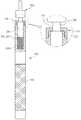
도 4는 본 발명의 척추교정기구를 나타낸 분해사시도, 도 5는 본 발명의 척추교정기구를 나타낸 결합사시도, 도 6은 본 발명의 척추교정기구를 나타낸 단면도, 도 7은 본 발명의 척추교정기구 중 다양한 형상을 갖는 접촉부재의 각 예를 나타낸 요부사시도, 도 8 내지 도 10은 본 발명의 척추교정기구를 이용하여 척추교정시술을 수행하는 과정을 나타낸 사용상태도, 도 11은 본 발명의 척추교정기구 중 완충부재의 다른 실시예를 나타낸 단면도 및 도 12 내지 도 14는 다른 실시예를 갖는 완충부재가 탑재된 본 발명의 척추교정기구를 이용하여 척추교정시술을 수행하는 과정을 나타낸 사용상태도이다.Figure 4 is an exploded perspective view showing a spinal correction mechanism of the present invention, Figure 5 is a combined perspective view showing a spinal correction mechanism of the present invention, Figure 6 is a cross-sectional view showing a spinal correction mechanism of the present invention, Figure 7 is a spinal correction mechanism of the present invention 8 to 10 is a state diagram showing a process of performing a chiropractic using the spinal correction mechanism of the present invention, Figure 11 is a spinal column of the
도시된 바와 같이, 본 발명의 척추교정기구는 크게 몸체(100), 접촉부재(200) 및 완충부재로 이루어진다.As shown, the chiropractic device of the present invention comprises a
먼저, 몸체(100)는 후부에 손잡이 영역(110)이 구비된다. 이처럼, 구비되는 손잡이 영역(110)에는 파지용 미세돌기들이 일정규칙으로 배치되어 있어 시술자가 척추교정시술 시 미끌어지지 않고 시술할 수 있도록 제공한다.First, the
상기 접촉부재(200)는 선단이 환자의 등 쪽 척추 부위에 접촉되어 전달되는 힘에 의해 잘못된 척추의 위치 즉, 좁혀진 뼈와 뼈 사이의 간극을 직접적으로 넓혀 주는 부재이다.The
이와 같은, 기능을 수행하는 접촉부재는 척추의 구분에 따라 그 형상이나 크기에 차이가 있다.As such, the contact member performing the function has a difference in shape or size depending on the classification of the spine.
도 7을 주로 참조하여, 도 7a에 도시된 접촉부재(200)의 경우 척추의 구분 중 경추 또는 천골 등에 이용되는데 그 용도는 먼저 경추의 경우 경추 극돌기를 타격하여 돌출된 경추 극돌기가 원위치로 올 수 있게 제공한다.Referring mainly to Figure 7, in the case of the
그리고 천골의 경우 좌우측면을 타격하여 좌우로 틀어진 천골 극돌기가 원위치로 올 수 있게 제공한다.And in the case of the sacrum strikes the left and right sides to provide the sacral spinous process that is twisted from side to side to the original position.
이처럼, 도 7a의 접촉부재(200)는 뼈와 뼈 사이의 간격이 좁은 곳에 이용되는 것으로, 그 형상 또한 얇은 판형을 갖는다.As such, the
아래 이미지는 도 7a의 사용예를 나타낸 것이다.The image below shows an example of use of FIG. 7A.


그리고 척추교정시술의 특성상 접촉부재(200)가 환부에 직접 접촉되기 때문에 위생상 위생 커버(220)를 씌워 사용하며, 환자는 개인마다 위생 커버(200)를 소지하거나 또는 시술장소에 비치하여 이용할 수 있다.In addition, the
이러한 위생 커버(220)의 재질은 폴리우레탄, 실리콘 및 고무 등을 이용할 수 있으며, 바람직하기로는 실리콘을 이용할 수 있다.
The
도 7b에 도시된 접촉부재(200a)의 경우 척추의 구분 중 경추, 흉추 또는 요추 등에 이용되는데 그 용도는 경추, 흉추 또는 요추의 극돌기 좌우측면을 타격하여 좌우로 틀어진 경추, 흉추 또는 요추의 극돌기가 원위치로 올 수 있게 제공한다.In the case of the contact member (200a) shown in Figure 7b is used in the cervical, thoracic or lumbar spine, etc. of the spine is divided into the cervical spine, thoracic or lumbar spine of the cervical spine, thoracic or lumbar spine by hitting the left and right sides of the spinous process Provide it to come home.
이처럼, 도 7b의 접촉부재(200a)는 뼈와 뼈 사이의 간격이 중간 정도인 곳에 이용되는 것으로, 그 형상은 정사각형에 준하는 형상을 갖는다.As such, the
아래 이미지는 도 7b의 사용예를 나타낸 것이다.The image below shows an example of use of FIG. 7B.


그리고 도 7b의 접촉부재(200a)에도 그 접촉부재(200a)의 형상에 대응되는 위생 커버(220a)가 환자 개인마다 구비되어 제공될 수 있다.
In addition, the sanitary cover 220a corresponding to the shape of the
도 7c에 도시된 접촉부재(200b)의 경우 척추의 구분 중 흉추, 요추 또는 천골 등에 이용되는데 그 용도는 흉추, 요추 또는 천골의 극돌기를 타격하여 돌출된 흉추, 요추 또는 천골의 극돌기가 원위치로 올 수 있게 제공한다.In the case of the contact member (200b) shown in Figure 7c is used in the thoracic spine, lumbar spine or sacrum during the division of the spine, its use is to strike the spinal spine of the thoracic, lumbar or sacrum protruding thoracic spine, lumbar spine or sacrum come to the original position. To be available.
이처럼, 도 7c의 접촉부재(200b)는 뼈와 뼈 사이의 간격이 넓은 곳에 이용되는 것으로, 그 형상은 장방향의 사각형상을 갖는다.As such, the
아래 이미지는 도 7c의 사용예를 나타낸 것이다.The image below shows an example of the use of FIG. 7C.

그리고 도 7c의 접촉부재(200b)에도 그 접촉부재(200b)의 형상에 대응되는 위생 커버(220b)가 환자 개인마다 구비되어 제공될 수 있다.The sanitary cover 220b corresponding to the shape of the
이처럼, 척추부위에 따라 다양한 크기 및 형상을 갖는 접촉부재의 경우 하나의 몸체(100)로 여러 접촉부재(200)를 착탈하여 선택사용할 수 있게 제공한다.
As such, in the case of a contact member having various sizes and shapes according to the spinal region, the
상기 완충부재는 몸체(100)의 선단 쪽에 접촉부재(200)를 연결시키되, 몸체(100)의 선단 쪽에 연결되는 접촉부재(200)가 몸체(100)의 후부로부터 가격되는 힘에 의해 몸체(100)의 후부 방향으로 탄성 이동되게 안내하는 부재이다.The buffer member is connected to the
이러한, 기능을 수행하는 완충부재는 다양한 실시예로 제공될 수 있다.Such a buffer member for performing a function may be provided in various embodiments.
제 1실시예에 따른 완충부재의 구성은 결합핀(310)과, 접촉부재(200)의 후단에 연결되는 것으로, 결합핀(310)의 직경보다 긴 길이(L)를 갖는 이동 안내용 장홈(211)이 형성된 결합대(210)와, 몸체(100)의 선단에 형성되는 수용공간(120)과, 몸체(100)의 측부에 형성되되, 수용공간(120)을 관통하여 형성되는 것으로, 결합대(210)의 이동 안내용 장홈(211)에 대응되는 위치에 형성되는 체결구멍(130)과, 탄성체(320)로 이루어짐으로써, 몸체(100)의 수용공간(120)에 탄성체(320)가 내입되고, 접촉부재(200)의 결합대(210)도 끼워진 상태에서 결합핀(310)이 결합대(210)의 이동 안내용 장홈(211) 및 몸체(100)의 체결구멍(130)을 통해 끼움 고정되는 구조를 갖는다.The configuration of the shock absorbing member according to the first embodiment is connected to the rear end of the
여기서, 결합대(210)에 형성된 이동 안내용 장홈(211)의 너비는 결합핀(310)이 안내용 장홈(211)의 길이(L) 방향을 따라 원활하게 이동될 수 있도록 결합핀(310)의 직경 정도(또는 조금 큰 정도)로 제작하는 것이 바람직하다.Here, the width of the movement guide
또한, 결합핀(310)은 몸체(100)의 체결구멍(130)에 관통 결합되어 고정된 구조이기 때문에, 실질적으로는 몸체(100)의 후단을 고무망치(1)로 가격 시 접촉부재(200)에 접촉된 탄성체(320)가 압착됨으로써, 접촉부재(200)가 몸체(100)의 후방쪽으로 슬라이딩 이동된다.In addition, since the
이때, 탄성 이동되는 거리는 수㎜ 정도이며 일예로, 1㎜ ~ 3㎜의 탄성 이동될 수 있다.In this case, the distance that is elastically moved is about a few mm, for example, may be 1 to 3 mm of elastic movement.
또한, 탄성체(320)는 다양한 종류를 선택하여 이용할 수 있다.In addition, the
일예로, 탄성체(320)는 도면에 도시된 것처럼 실리콘, 우레탄 및 고무 등을 포함하는 합성수지계열을 이용하거나 또는 스프링을 이용할 수 있다.For example, the
이처럼, 제 1실시예에 따른 완충부재를 갖는 본 발명의 척추교정기구를 이용하여 척추교정시술 과정을 설명하면 다음과 같다.As described above, when the chiropractic procedure using the chiropractic device of the present invention having the buffer member according to the first embodiment is described.
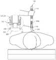
먼저, 도 8을 주로 참조하여, 시술자는 바닥에 엎드린 환자의 등 쪽 척추 부위 중 척추교정을 수행할 등 쪽 척추 부위에 몸체(100)의 선부에 연결된 접촉부재(200)를 접촉한다.First, referring mainly to FIG. 8, the operator contacts the
이때, 몸체(100)의 결합핀(310)을 통해 연결된 접촉부재(200)는 접촉부재(200)를 이루는 결합대(210)의 이동안내용 장홈(211)에 그 결합핀(310)이 중첩된 상태로, 결합핀(310)은 이동안내용 장홈(211)의 아래 쪽에 위치된 상태로 연결된 구조를 갖는다.At this time, the
도 9를 주로 참조하여, 이후, 시술자는 등 쪽 척추 부위에 위치하는 몸체(100)의 후단을 고무망치(1)를 이용하여 가격하면, 그 가격된 힘이 몸체(100)의 선부에 연결된 접촉부재(200)에 까지 전달되고, 그 전달되는 가격된 힘에 의해 접촉부재(200)와 접촉된 탄성체(320)에도 전달되면서 탄성체(320)가 탄성 압착된다.Referring mainly to FIG. 9, after the operator strikes the rear end of the
이에 따라, 접촉부재(200)는 상부로 이동하게 되는데 즉, 접촉부재(200)를 이루는 결합대(210)의 이동안내용 장홈(211)에 중첩된 상태로 연결된 결합핀(310)은 이동안내용 장홈(211)의 아래 쪽에서 위쪽으로 이동배치됨으로써, 접촉부재(200)가 상부로 이동할 수 있게 안내한다.Accordingly, the
도 10을 주로 참조하여, 이후, 몸체(100)에 가격된 힘이 제거되면, 탄성압착된 탄성체(320)는 복원되면서 접촉된 접촉부재(200)를 밀게 되고 이로 인해, 이동안내용 장홈(211)의 위쪽에 위치하는 결합핀(310)은 다시 원위치인 이동안내용 장홈(211)의 아래 쪽에 이동 위치된다.Referring to FIG. 10, afterwards, when the force charged to the
이처럼, 고무망치(1)를 통해 몸체(100)에 전달되는 가격의 힘 중 일부가 탄성체를 압착하는데 사용되어 완충됨으로써, 척추교정시술 중 타격하는 힘에 의해 발생되는 통증의 세기를 반감시켜주는 이점을 제공한다.As such, a portion of the price force transmitted to the
이와 같은, 타격의 반복과정을 통해 시술자는 척추교정시술을 수행한다.
As such, the operator performs the spine correction procedure through the repeated process of the blow.
그리고 제 2실시예에 따른 완충부재의 구성은 몸체(100)의 선단에 형성되는 수용공간(120)과; 몸체(100)의 수용공간(120)에 내입되는 탄성체(320a)와; 접촉부재(200)의 후단에 연결되는 것으로, 외주연에 걸림턱(231)이 확장돌출된 돌출 결합대(230)와; 접촉부재(200)의 돌출 결합대(230)가 몸체(100)의 수용공간(120)에 내입되어 탄성체(320a)에 접촉된 상태에서 몸체(100)의 수용공간(120) 밖으로 이탈되지 않도록 수용공간(120)을 이루는 상기 몸체(100)의 선단 내측으로 확장되는 이탈방지대(141)로 이루어진다.And the configuration of the buffer member according to the second embodiment includes a receiving
이처럼, 구성되는 제 2실시예에 따른 완충부재는 제 1실시예와 그 작동기능이 동일하기에 동일한 구성 및 그에 따른 작동관계의 설명은 언급하지 않기로 한다.As such, the shock absorbing member according to the second embodiment of the configuration is not the description of the same configuration and the operation relations according to the same operation because the operation function is the same as the first embodiment.
그리고 제 2실시예에 따른 완충부재와 제 1실시예에 따른 완충부재 간의 차이는 몸체(100)와 접촉부재(200) 간의 연결방식이다.The difference between the buffer member according to the second embodiment and the buffer member according to the first embodiment is a connection method between the
즉, 제 2실시예에 따른 완충부재에서는 이탈방지대(141)가 구비된 몸체(100)의 선단 부근이 착탈 가능하도록 착탈부재(140)를 구비하여 도면에서처럼, 나선 체결 또는 억지끼움 방식을 통해 접촉부재(200)를 이루는 돌출 결합대(230)의 걸림턱(231)이 착탈부재(140)에 구비된 이탈방지대(141)에 걸려 연결되는 구조로서, 몸체(100)로부터 접촉부재(200)의 착탈을 보다 용이하게 제공하기 위하여 채택될 수 있다.
That is, in the shock absorbing member according to the second embodiment, the
1 : 고무망치10 : 원통 몸체
11 : 타격면12 : 파지영역
20 : 외피100 : 몸체
110 : 손잡이 영역120 : 수용공간
130 : 체결구멍140 : 착탈부재
141 : 이탈방지대200,200a,200b : 접촉부재
210 : 결합대211 : 이동안내용 장홈
220,220a,220b : 위생커버230 : 돌출결합대
231 : 걸림턱310 : 결합핀
320,320a : 탄성체1: rubber hammer 10: cylindrical body
11: hitting surface 12: gripping area
20: sheath 100: body
110: handle area 120: accommodation space
130: fastening hole 140: removable member
141: departure stopper 200,200a, 200b: contact member
210: combiner 211: long guide for movement guide
220,220a, 220b: sanitary cover 230: protrusion coupling
231: engaging jaw 310: coupling pin
320,320a: elastic body
Claims (8)
Translated fromKorean선단이 환자의 등 쪽 척추 부위에 접촉되는 접촉부재(200)와;
상기 몸체(100)의 선단 쪽에 상기 접촉부재(200)를 연결시키되, 상기 몸체(100)의 선단 쪽에 연결되는 상기 접촉부재(200)가 상기 몸체(100)의 후부로부터 가격되는 힘에 의해 상기 몸체(100)의 후부 방향으로 탄성 이동되게 안내하는 완충부재;를 포함하는 것을 특징으로 하는 척추교정기구.
A body 100 having a handle region 110 at the rear;
A contact member 200 whose tip is in contact with the dorsal spine region of the patient;
The contact member 200 is connected to the tip side of the body 100, but the contact member 200 connected to the tip side of the body 100 is priced from the rear of the body 100 by the force. And a shock absorbing member for guiding elastic movement in the rear direction of the (100).
상기 완충부재는,
결합핀(310)과;
상기 접촉부재(200)의 후단에 연결되는 것으로, 상기 결합핀(310)의 직경보다 긴 길이(L)를 갖는 이동 안내용 장홈(211)이 형성된 결합대(210)와;
상기 몸체(100)의 선단에 형성되는 수용공간(120)과;
상기 몸체(100)의 측부에 형성되되, 상기 수용공간(120)을 관통하여 형성되는 것으로, 상기 결합대(210)의 이동 안내용 장홈(211)에 대응되는 위치에 형성되는 체결구멍(130)과;
탄성체(320);로 이루어져, 상기 몸체(100)의 수용공간(120)에 상기 탄성체(320)가 내입되고, 상기 접촉부재(200)의 결합대(210)도 끼워진 상태에서 상기 결합핀(310)이 상기 결합대(210)의 이동 안내용 장홈(211) 및 상기 몸체(100)의 체결구멍(130)을 통해 끼움 고정되는 구조를 갖는 것을 특징으로 하는 척추교정기구.
The method of claim 1,
The buffer member,
A coupling pin 310;
A coupling table 210 connected to the rear end of the contact member 200 and having a long guide groove 211 having a length L longer than the diameter of the coupling pin 310;
An accommodation space 120 formed at the tip of the body 100;
Is formed on the side of the body 100, is formed through the receiving space 120, the fastening hole 130 is formed at a position corresponding to the movement guide long groove 211 of the coupling table 210 and;
An elastic body 320; the elastic body 320 is embedded in the receiving space 120 of the body 100, the coupling pin 310 in the state in which the coupling table 210 of the contact member 200 is also fitted. ) Is a chiropractic device characterized in that it has a structure that is fitted through the fastening hole 130 of the guide (210) and the body 100 for the movement guide of the coupling table (210).
상기 탄성체(320)는 실리콘, 우레탄, 고무 중 어느 하나인 것을 특징으로 하는 척추교정기구.
The method of claim 2,
The elastic body 320 is a chiropractic device, characterized in that any one of silicon, urethane, rubber.
상기 탄성체(320)는 스프링인 것을 특징으로 하는 척추교정기구.
The method of claim 2,
The elastic body 320 is a chiropractic, characterized in that the spring.
상기 완충부재는,
상기 몸체(100)의 선단에 형성되는 수용공간(120)과;
상기 몸체(100)의 수용공간(120)에 내입되는 탄성체(320a)와;
상기 접촉부재(200)의 후단에 연결되는 것으로, 외주연에 걸림턱(231)이 확장돌출된 돌출 결합대(230)와;
상기 접촉부재(200)의 돌출 결합대(230)가 상기 몸체(100)의 수용공간(120)에 내입되어 상기 탄성체(320a)에 접촉된 상태에서 상기 몸체(100)의 수용공간(120) 밖으로 이탈되지 않도록 상기 수용공간(120)을 이루는 상기 몸체(100)의 선단 내측으로 확장되는 이탈방지대(141);로 이루어진 것을 특징으로 하는 척추교정기구.
The method of claim 1,
The buffer member,
An accommodation space 120 formed at the tip of the body 100;
An elastic body 320a embedded in the accommodation space 120 of the body 100;
It is connected to the rear end of the contact member 200, the protruding engaging table 230 is extended projection protrusion 231 on the outer periphery;
The protruding coupler 230 of the contact member 200 is inserted into the receiving space 120 of the body 100 to be out of the receiving space 120 of the body 100 in contact with the elastic body 320a. Spinal orthodontic appliance characterized in that consisting of; a departure preventing member (141) extending to the inner side of the front end of the body constituting the receiving space 120 so as not to be separated.
상기 이탈방지대(141)가 구비된 상기 몸체(100)의 선단 부근은 착탈 가능하도록 착탈부재(140);가 구비되는 것을 특징으로 하는 척추교정기구.
The method of claim 5,
Spinal orthodontic mechanism, characterized in that provided; the detachable member 140, the detachable member 140 is detachable so as to be detachable near the front end of the body 100 is provided with the departure prevention member (141).
상기 탄성체(320a)는 실리콘, 우레탄, 고무 중 어느 하나인 것을 특징으로 하는 척추교정기구.
The method of claim 5,
The elastic body (320a) is a chiropractic, characterized in that any one of silicone, urethane, rubber.
상기 탄성체(320a)는 스프링인 것을 특징으로 하는 척추교정기구.The method of claim 5,
The elastic body (320a) is a chiropractic, characterized in that the spring.
Priority Applications (1)
| Application Number | Priority Date | Filing Date | Title |
|---|---|---|---|
| KR1020120075416AKR101207389B1 (en) | 2012-07-11 | 2012-07-11 | Device for spinal adjustment |
Applications Claiming Priority (1)
| Application Number | Priority Date | Filing Date | Title |
|---|---|---|---|
| KR1020120075416AKR101207389B1 (en) | 2012-07-11 | 2012-07-11 | Device for spinal adjustment |
Publications (2)
| Publication Number | Publication Date |
|---|---|
| KR20120085229A KR20120085229A (en) | 2012-07-31 |
| KR101207389B1true KR101207389B1 (en) | 2012-12-04 |
Family
ID=46715867
Family Applications (1)
| Application Number | Title | Priority Date | Filing Date |
|---|---|---|---|
| KR1020120075416AActiveKR101207389B1 (en) | 2012-07-11 | 2012-07-11 | Device for spinal adjustment |
Country Status (1)
| Country | Link |
|---|---|
| KR (1) | KR101207389B1 (en) |
Cited By (1)
| Publication number | Priority date | Publication date | Assignee | Title |
|---|---|---|---|---|
| US10426691B2 (en) | 2015-05-18 | 2019-10-01 | Myorom Sports Med Ii, Llc | Portable therapeutic apparatus |
Families Citing this family (1)
| Publication number | Priority date | Publication date | Assignee | Title |
|---|---|---|---|---|
| KR101972737B1 (en)* | 2018-08-31 | 2019-04-25 | 김형민 | Spinal Striking Apparatus |
Citations (1)
| Publication number | Priority date | Publication date | Assignee | Title |
|---|---|---|---|---|
| JP2002248109A (en) | 2001-01-23 | 2002-09-03 | Depuy Acromed Inc | Medical care shock device and its system |
- 2012
- 2012-07-11KRKR1020120075416Apatent/KR101207389B1/enactiveActive
Patent Citations (1)
| Publication number | Priority date | Publication date | Assignee | Title |
|---|---|---|---|---|
| JP2002248109A (en) | 2001-01-23 | 2002-09-03 | Depuy Acromed Inc | Medical care shock device and its system |
Cited By (1)
| Publication number | Priority date | Publication date | Assignee | Title |
|---|---|---|---|---|
| US10426691B2 (en) | 2015-05-18 | 2019-10-01 | Myorom Sports Med Ii, Llc | Portable therapeutic apparatus |
Also Published As
| Publication number | Publication date |
|---|---|
| KR20120085229A (en) | 2012-07-31 |
Similar Documents
| Publication | Publication Date | Title |
|---|---|---|
| KR101207389B1 (en) | Device for spinal adjustment | |
| US10966552B2 (en) | Cushioning posterior fulcrum back shaper | |
| KR101585221B1 (en) | Combined acupressure bar and acupressure pillow | |
| KR101601972B1 (en) | Body versatile calibration instrument | |
| KR20150051196A (en) | Shoulder stretching massager | |
| JP4246241B2 (en) | Affected part projecting member for orthopedic appliances | |
| KR101606202B1 (en) | Lumber traction device and body correction apparatus with the same | |
| KR100935803B1 (en) | Finger pressure device for the cervical vertebral | |
| JP2015524716A (en) | Chest stabilization device | |
| KR20170135000A (en) | Device for cervical therapy | |
| JP2002315767A (en) | Vertebra correction device | |
| CN207979762U (en) | The preceding road of atlas and axis, which resets, to be rebuild internal fixation plate and uses mating instrument with fixed plate | |
| KR101253663B1 (en) | Rod holder for minimal invasive surgery | |
| KR101675979B1 (en) | Equipment for exercing cervical | |
| CN213077320U (en) | Muscle strength trainer after bone joint operation | |
| JP2006102256A (en) | Correcting apparatus | |
| KR101220953B1 (en) | A Rasp Handle | |
| KR200450660Y1 (en) | Pelvic correction device | |
| KR101714331B1 (en) | The fascia healing device | |
| KR100750631B1 (en) | Spinal traction device | |
| JP6671111B2 (en) | Shiatsu | |
| KR101401508B1 (en) | Apparatus for correcting facet joints of cervical vertebrae | |
| CN210205022U (en) | Electric spine rehabilitation bed | |
| CN220655909U (en) | Point type spinal column corrector | |
| US12324957B2 (en) | Head pressure-resistant device for neck exercises |
Legal Events
| Date | Code | Title | Description |
|---|---|---|---|
| A201 | Request for examination | ||
| PA0109 | Patent application | Patent event code:PA01091R01D Comment text:Patent Application Patent event date:20120711 | |
| PA0201 | Request for examination | ||
| A302 | Request for accelerated examination | ||
| PA0302 | Request for accelerated examination | Patent event date:20120713 Patent event code:PA03022R01D Comment text:Request for Accelerated Examination Patent event date:20120711 Patent event code:PA03021R01I Comment text:Patent Application | |
| PG1501 | Laying open of application | ||
| E902 | Notification of reason for refusal | ||
| PE0902 | Notice of grounds for rejection | Comment text:Notification of reason for refusal Patent event date:20120911 Patent event code:PE09021S01D | |
| E701 | Decision to grant or registration of patent right | ||
| PE0701 | Decision of registration | Patent event code:PE07011S01D Comment text:Decision to Grant Registration Patent event date:20121107 | |
| GRNT | Written decision to grant | ||
| PR0701 | Registration of establishment | Comment text:Registration of Establishment Patent event date:20121127 Patent event code:PR07011E01D | |
| PR1002 | Payment of registration fee | Payment date:20121127 End annual number:3 Start annual number:1 | |
| PG1601 | Publication of registration | ||
| FPAY | Annual fee payment | Payment date:20151012 Year of fee payment:4 | |
| PR1001 | Payment of annual fee | Payment date:20151012 Start annual number:4 End annual number:4 | |
| FPAY | Annual fee payment | Payment date:20161117 Year of fee payment:5 | |
| PR1001 | Payment of annual fee | Payment date:20161117 Start annual number:5 End annual number:5 | |
| FPAY | Annual fee payment | Payment date:20190904 Year of fee payment:8 | |
| PR1001 | Payment of annual fee | Payment date:20190904 Start annual number:8 End annual number:8 | |
| PR1001 | Payment of annual fee | Payment date:20201013 Start annual number:9 End annual number:9 | |
| PR1001 | Payment of annual fee | Payment date:20211013 Start annual number:10 End annual number:10 |