KR101207198B1 - Board inspection apparatus - Google Patents
Board inspection apparatusDownload PDFInfo
- Publication number
- KR101207198B1 KR101207198B1KR1020100004398AKR20100004398AKR101207198B1KR 101207198 B1KR101207198 B1KR 101207198B1KR 1020100004398 AKR1020100004398 AKR 1020100004398AKR 20100004398 AKR20100004398 AKR 20100004398AKR 101207198 B1KR101207198 B1KR 101207198B1
- Authority
- KR
- South Korea
- Prior art keywords
- camera
- beam splitter
- light
- imaging lens
- substrate
- Prior art date
- Legal status (The legal status is an assumption and is not a legal conclusion. Google has not performed a legal analysis and makes no representation as to the accuracy of the status listed.)
- Active
Links
Images


Classifications
- G—PHYSICS
- G01—MEASURING; TESTING
- G01N—INVESTIGATING OR ANALYSING MATERIALS BY DETERMINING THEIR CHEMICAL OR PHYSICAL PROPERTIES
- G01N21/00—Investigating or analysing materials by the use of optical means, i.e. using sub-millimetre waves, infrared, visible or ultraviolet light
- G01N21/84—Systems specially adapted for particular applications
- G01N21/88—Investigating the presence of flaws or contamination
- G01N21/95—Investigating the presence of flaws or contamination characterised by the material or shape of the object to be examined
- G01N21/9501—Semiconductor wafers
Landscapes
- General Health & Medical Sciences (AREA)
- Health & Medical Sciences (AREA)
- Life Sciences & Earth Sciences (AREA)
- Chemical & Material Sciences (AREA)
- Analytical Chemistry (AREA)
- Biochemistry (AREA)
- Physics & Mathematics (AREA)
- General Physics & Mathematics (AREA)
- Immunology (AREA)
- Pathology (AREA)
- Investigating Materials By The Use Of Optical Means Adapted For Particular Applications (AREA)
- Length Measuring Devices By Optical Means (AREA)
- Studio Devices (AREA)
Abstract
Translated fromKoreanDescription
Translated fromKorean본 발명은 기판 검사장치에 관한 것으로, 더욱 상세하게는 기판 표면의 3차원 형상을 검사할 수 있는 기판 검사장치에 관한 것이다.The present invention relates to a substrate inspection apparatus, and more particularly to a substrate inspection apparatus capable of inspecting a three-dimensional shape of the substrate surface.
기판 표면의 3차원 형상을 검사할 수 있는 기판 검사장치는 검사물체로 광을 제공하는 조명모듈 및 상기 검사물체로부터 반사된 광을 촬상모듈을 구비하고, 상기 촬상모듈은 상기 검사물체에서 반사된 광을 투과시키는 결상렌즈 및 상기 결상렌즈를 투과한 광을 촬상하는 카메라를 구비한다.A substrate inspection apparatus capable of inspecting a three-dimensional shape of a substrate surface includes an illumination module for providing light to an inspection object and an imaging module for reflecting light reflected from the inspection object, wherein the imaging module includes light reflected from the inspection object. An imaging lens for transmitting the light and a camera for imaging the light transmitted through the imaging lens.
최근에 상기 검사물체의 사이즈가 점점 커짐에 따라, 상기 카메라가 촬상할 수 있는 촬상 가능영역이 상기 검사물체의 사이즈에 비해 상대적으로 작아지고 있다. 그 결과, 최근에 개발된 기판 검사장치의 촬상모듈은 상기 검사물체의 사이즈에 대응하여 복수개의 카메라들과 이와 대응되는 복수개의 결상렌즈들을 구비하고 있다.In recent years, as the size of the inspection object becomes larger, the imageable area that the camera can capture is relatively smaller than the size of the inspection object. As a result, the recently developed imaging module of the substrate inspection apparatus includes a plurality of cameras and a plurality of imaging lenses corresponding to the size of the inspection object.
그러나, 상기 복수개의 결상렌즈들을 통해 상기 검사물체를 검사할 경우, 상기 결상렌즈들 간의 광축 차이, 상기 결상렌즈들 간의 배율 차이, 상기 결상렌즈들과 상기 검사기판 사이의 거리 차이 등에 의해 상기 카메라들에 촬상된 이미지들 사이에 왜곡이 발생되어 상기 검사기판의 검사 정밀도가 감소될 수 있다. 또한, 상기 카메라들에서 촬상된 이미지들에 대한 왜곡을 보상하여 하나의 통합 이미지로 합성하는 과정에 매우 복잡한 알고리즘이 필요할 수 있다.However, when the inspection object is inspected through the plurality of imaging lenses, the cameras may differ due to an optical axis difference between the imaging lenses, a magnification difference between the imaging lenses, and a distance difference between the imaging lenses and the inspection substrate. Distortion may occur between the images picked up on the screen, thereby reducing the inspection precision of the inspection substrate. In addition, a very complex algorithm may be required in the process of compensating for the distortion of the images captured by the cameras and synthesizing them into one integrated image.
따라서, 본 발명은 상기 문제점을 해결하고자 하는 것으로, 본 발명의 해결하고자 하는 과제는 검사 정밀도의 향상 및 알고리즘의 단순화를 이룰 수 있고, 보다 더 넓은 영역을 검사할 수 있는 기판 검사장치를 제공하는 것이다. 또한, 다수개의 카메라를 적용한 구조에 있어서 검사장비의 크기를 감소시키는 데에 있다.Therefore, the present invention is to solve the above problems, the problem to be solved by the present invention is to provide a substrate inspection apparatus that can improve the inspection precision and simplify the algorithm, and can inspect a wider area. . In addition, to reduce the size of the inspection equipment in the structure to which a plurality of cameras are applied.
본 발명의 일 실시예에 의한 기판 검사장치은 적어도 하나의 조명모듈, 결상렌즈, 제1 빔 스플리터(beam splitter), 제1 카메라 및 제2 카메라를 포함한다.A substrate inspection apparatus according to an embodiment of the present invention includes at least one lighting module, an imaging lens, a first beam splitter, a first camera, and a second camera.
상기 조명모듈은 검사기판으로 광을 제공하고, 상기 결상렌즈는 상기 검사기판로부터 반사된 광을 투과시킨다. 상기 제1 빔 스플리터는 상기 결상렌즈를 투과한 광 중 일부를 투과시키고 나머지를 반사시킨다. 상기 제1 카메라는 상기 제1 빔 스플리터를 투과한 광(이하, '투과광'이라 함)을 인가받아 촬상하고, 상기 제2 카메라는 상기 제1 빔 스플리터에서 반사된 광(이하, '반사광'이라 함)을 인가받아 촬상한다.The illumination module provides light to the test substrate, and the imaging lens transmits the light reflected from the test substrate. The first beam splitter transmits a part of the light transmitted through the imaging lens and reflects the rest. The first camera is imaged by receiving the light transmitted through the first beam splitter (hereinafter referred to as 'transmission light'), and the second camera is referred to as light reflected by the first beam splitter (hereinafter referred to as 'reflected light'). Image is taken.
상기 제1 빔 스플리터는 상기 결상렌즈로부터 인가되는 광 중 일부를 투과시키고, 나머지를 반사시키는 제1 반사면을 포함할 수 있다. 이때, 상기 제1 반사면은 상기 결상렌즈의 기준면과 소정의 각도를 이룰 수 있고, 상기 제1 카메라 및 상기 제2 카메라는 상기 검사기판의 서로 다른 영역을 촬상할 수 있다. 이때, 상기 제1 카메라 및 상기 제2 카메라는 서로 다른 방향으로 배치될 수 있다. 또한, 상기 제1 반사면은 상기 결상렌즈로부터 인가되는 광 중 약 50%를 투과시키고, 나머지 약 50%를 반사시킬 수 있다.The first beam splitter may include a first reflective surface that transmits a part of light applied from the imaging lens and reflects the rest. In this case, the first reflective surface may form a predetermined angle with the reference surface of the imaging lens, and the first camera and the second camera may capture different areas of the inspection substrate. In this case, the first camera and the second camera may be disposed in different directions. In addition, the first reflecting surface may transmit about 50% of the light applied from the imaging lens and reflect the remaining about 50%.
상기 제1 카메라의 중심과 상기 결상렌즈의 중심이 서로 엇갈리게 배치될 수 있다. 여기서, 상기 제1 카메라의 촬상소자의 폭을 i라고 하고, 상기 제1 카메라의 촬상소자의 중심과 상기 결상렌즈의 중심 간의 수평거리를 b라고 하면, i ≥ 2b 인 관계를 만족할 수 있다. 또한, 상기 제1 카메라에 의해 측정되는 제1 영역과 상기 제2 카메라에 의해 측정되는 제2 영역의 적어도 일부 영역은 서로 중첩될 수 있다.The center of the first camera and the center of the imaging lens may be alternately disposed. Here, when the width of the image pickup device of the first camera is i and the horizontal distance between the center of the image pickup device of the first camera and the center of the imaging lens is b, a relationship of i ≧ 2b may be satisfied. In addition, at least a portion of the first area measured by the first camera and the second area measured by the second camera may overlap each other.
상기 기판 검사장치는 제2 빔 스플리터 및 제3 카메라를 더 포함할 수 있다. 상기 제2 빔 스플리터는 상기 제1 빔 스플리터 및 상기 제1 카메라 사이에 배치되고, 상기 투과광 중 일부를 투과시켜 상기 제1 카메라로 제공하고, 나머지를 반사시킨다. 상기 제3 카메라는 상기 제2 빔 스플리터에서 반사된 광을 인가받아 촬상한다. 이때, 상기 제2 빔 스플리터는 상기 투과광 중 일부를 투과시키고, 나머지를 반사시키는 제2 반사면을 포함할 수 있고, 상기 제2 반사면은 상기 결상렌즈의 기준면과 소정의 각도를 이룰 수 있다.The substrate inspecting apparatus may further include a second beam splitter and a third camera. The second beam splitter is disposed between the first beam splitter and the first camera, transmits a part of the transmitted light to the first camera, and reflects the rest. The third camera receives the light reflected from the second beam splitter and captures the image. In this case, the second beam splitter may include a second reflecting surface that transmits a part of the transmitted light and reflects the rest, and the second reflecting surface may form a predetermined angle with a reference plane of the imaging lens.
또한, 상기 기판 검사장치는 제3 빔 스플리터 및 제4 카메라를 더 포함할 수 있다. 상기 제3 빔 스플리터는 상기 제1 빔 스플리터 및 상기 반사광 카메라 사이에 배치되고, 상기 반사광 중 일부를 투과시켜 상기 제2 카메라로 제공하고, 나머지를 반사시킨다. 상기 제4 카메라는 상기 제3 빔 스플리터에서 반사된 광을 인가받아 촬상한다. 이때, 상기 제3 빔 스플리터는 상기 반사광 중 일부를 투과시키고, 나머지를 반사시키는 제3 반사면을 포함할 수 있고, 상기 제3 반사면은 상기 결상렌즈의 기준면과 소정의 각도를 이룰 수 있다.In addition, the substrate inspection apparatus may further include a third beam splitter and a fourth camera. The third beam splitter is disposed between the first beam splitter and the reflected light camera, transmits a part of the reflected light to the second camera, and reflects the rest. The fourth camera receives the light reflected from the third beam splitter and captures the image. In this case, the third beam splitter may include a third reflecting surface that transmits a part of the reflected light and reflects the rest, and the third reflecting surface may form a predetermined angle with a reference plane of the imaging lens.
이와 같은 기판 검사장치에 따르면, 제1 빔 스플리터가 검사기판에서 반사된 광을 양분하여 두 개의 카메라들에 각각 제공함에 따라, 하나의 결상렌즈를 이용하여 측정영역의 확장이 가능하다. 그 결과, 종래와 같이 결상렌즈들 간의 광축 또는 배율 차이, 상기 결상렌즈들과 상기 검사기판 사이의 거리 차이 등에 의해 상기 검사기판의 검사 정밀도가 감소되는 것을 방지할 수 있고, 또한 상기 두 개의 카메라들에서 촬상된 이미지들을 하나의 통합 이미지로 합성하는 알고리즘이 종래에 비해 단순해질 수 있다. 또한 복수개의 카메라를 적용함에 있어서 카메라를 서로 다른 방향으로 배치하여 검사장치의 부피를 감소시킬 수 있다.According to such a substrate inspection apparatus, since the first beam splitter divides the light reflected from the inspection substrate and provides the two cameras to each of the two cameras, the measurement region can be expanded by using one imaging lens. As a result, the inspection precision of the inspection substrate can be prevented from being reduced by the optical axis or magnification difference between the imaging lenses, the distance difference between the imaging lenses and the inspection substrate, and the two cameras. The algorithm for synthesizing the captured images into a single integrated image can be simplified compared to the conventional art. In addition, in applying a plurality of cameras it is possible to reduce the volume of the inspection apparatus by placing the cameras in different directions.
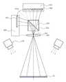
도 1은 본 발명의 제1 실시예에 따른 기판 검사장치를 나타낸 단면도이다.
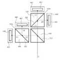
도 2는 도 1의 기판 검사장치 중 빔 스플리터와 카메라를 개념적으로 도시한 단면도이다.
도 3은 도 1의 기판 검사장치 중 조명모듈을 확대해서 도시한 도면이다.
도 4는 도 1의 검사장치 중 검사기판, 결상렌즈 및 제1 카메라 사이의 관계를 설명하기 위한 도면이다.
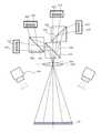
도 5는 본 발명의 제2 실시예에 따른 기판 검사장치를 나타낸 단면도이다.
도 6은 도 5의 기판 검사장치 중 빔 스플리터와 카메라를 개념적으로 도시한 단면도이다.1 is a cross-sectional view showing a substrate inspection apparatus according to a first embodiment of the present invention.
2 is a cross-sectional view conceptually illustrating a beam splitter and a camera in the substrate inspection apparatus of FIG. 1.
3 is an enlarged view of an illumination module of the substrate inspection apparatus of FIG. 1.
4 is a view for explaining a relationship between an inspection substrate, an imaging lens, and a first camera in the inspection apparatus of FIG. 1.
5 is a cross-sectional view illustrating a substrate inspecting apparatus according to a second exemplary embodiment of the present invention.
6 is a cross-sectional view conceptually illustrating a beam splitter and a camera in the substrate inspection apparatus of FIG. 5.
본 발명은 다양한 변경을 가할 수 있고 여러 가지 형태를 가질 수 있는 바, 특정 실시예들을 도면에 예시하고 본문에 상세하게 설명하고자 한다.The present invention is capable of various modifications and various forms, and specific embodiments are illustrated in the drawings and described in detail in the text.
그러나, 이는 본 발명을 특정한 개시 형태에 대해 한정하려는 것이 아니며, 본 발명의 사상 및 기술 범위에 포함되는 모든 변경, 균등물 내지 대체물을 포함하는 것으로 이해되어야 한다. 제1, 제2 등의 용어는 다양한 구성 요소들을 설명하는데 사용될 수 있지만, 상기 구성 요소들은 상기 용어들에 의해 한정되어서는 안된다. 상기 용어들은 하나의 구성 요소를 다른 구성 요소로부터 구별하는 목적으로만 사용된다. 예를 들어, 본 발명의 권리 범위를 벗어나지 않으면서 제1 구성 요소는 제2 구성 요소로 명명될 수 있고, 유사하게 제2 구성 요소도 제1 구성 요소로 명명될 수 있다.It should be understood, however, that the invention is not intended to be limited to the particular forms disclosed, but includes all modifications, equivalents, and alternatives falling within the spirit and scope of the invention. The terms first, second, etc. may be used to describe various elements, but the elements should not be limited by the terms. The terms are used only for the purpose of distinguishing one component from another. For example, without departing from the scope of the present invention, the first component may be referred to as a second component, and similarly, the second component may also be referred to as a first component.
본 출원에서 사용한 용어는 단지 특정한 실시예들을 설명하기 위해 사용된 것으로, 본 발명을 한정하려는 의도가 아니다. 단수의 표현은 문맥상 명백하게 다르게 뜻하지 않는 한, 복수개의표현을 포함한다. 본 출원에서, "포함하다" 또는 "가지다" 등의 용어는 명세서에 기재된 특징, 숫자, 단계, 동작, 구성 요소, 부분품 또는 이들을 조합한 것이 존재함을 지정하려는 것이지, 하나 또는 그 이상의 다른 특징들이나 숫자, 단계, 동작, 구성 요소, 부분품 또는 이들을 조합한 것들의 존재 또는 부가 가능성을 미리 배제하지 않는 것으로 이해되어야 한다.The terminology used herein is for the purpose of describing particular embodiments only and is not intended to be limiting of the invention. Singular expressions include plural expressions unless the context clearly indicates otherwise. In this application, the terms "comprise" or "having" are intended to indicate that there is a feature, number, step, action, component, part, or combination thereof described in the specification, and that one or more other features It should be understood that it does not exclude in advance the possibility of the presence or addition of numbers, steps, actions, components, parts or combinations thereof.
이하, 첨부한 도면들을 참조하여, 본 발명의 바람직한 실시예들을 보다 상세하게 설명한다.
DETAILED DESCRIPTION OF THE PREFERRED EMBODIMENTS Reference will now be made in detail to the preferred embodiments of the present invention, examples of which are illustrated in the accompanying drawings.
<실시예 1>≪ Example 1 >
도 1은 본 발명의 제1 실시예에 따른 기판 검사장치를 나타낸 단면도이고, 도 2는 도 1의 기판 검사장치 중 빔 스플리터와 카메라를 개념적으로 도시한 단면도이며, 도 3은 도 1의 기판 검사장치 중 조명모듈을 확대해서 도시한 도면이다.1 is a cross-sectional view showing a substrate inspection apparatus according to a first embodiment of the present invention, FIG. 2 is a cross-sectional view conceptually showing a beam splitter and a camera of the substrate inspection apparatus of FIG. 1, and FIG. 3 is a substrate inspection of FIG. 1. Figure is an enlarged view of the lighting module of the device.
도 1, 도 2 및 도 3을 참조하면, 본 실시예에 의한 기판 검사장치는 스테이지(미도시)에 배치된 검사기판(10)의 표면의 3차원 형상을 검사하는 검사장치로, 적어도 하나의 조명모듈(100), 결상렌즈(200), 제1 빔 스플리터(310), 제1 카메라(410), 제2 카메라(420) 및 제어시스템(미도시)을 포함한다.1, 2 and 3, the substrate inspection apparatus according to the present embodiment is an inspection device for inspecting a three-dimensional shape of the surface of the
상기 조명모듈(100)은 조명유닛(110), 격자유닛(120), 투사렌즈(130) 및 격자 이송유닛(140)을 포함할 수 있다. 상기 조명유닛(110)은 조명원과 적어도 하나의 렌즈로 구성되어 광을 발생시키고, 상기 격자유닛(120)은 상기 조명유닛(110)의 하부에 배치되어 상기 조명유닛(110)에서 발생된 광을 격자무늬 패턴을 갖는 격자 패턴광으로 변경시킨다. 상기 투사렌즈(130)는 상기 격자유닛(120)의 하부에 배치되어 상기 격자유닛(120)으로부터 출사된 상기 격자 패턴광을 투과시킨다. 상기 격자 이송유닛(140)은 상기 격자유닛(120)을 사전에 정해된 획수만큼 일정 피치씩 이동시킨다.The
상기 조명모듈(100)의 개수는 2개, 3개, 4개 또는 그 이상일 수 있으며, 예를 들어, 상기 조명모듈(100)의 개수가 4개일 경우, 정사각형의 각 꼭지점에 상기 조명모듈(100)이 배치될 수 있다. 이때, 상기 검사기판(10)의 중심은 상기 정사각형의 중심과 실질적으로 일치하는 것이 바람직하다.The number of the
상기 결상렌즈(200)는 상기 검사기판(10)으로부터 반사된 상기 격자 패턴광을 투과시켜 상기 제1 빔 스플리터(310)로 제공한다. 상기 결상렌즈(200)의 기준면(210)은 상기 검사기판(10)과 실질적으로 평행하게 배치될 수 있고, 또한 상기 결상렌즈(200)의 중심은 상기 검사기판(10)의 중심과 실질적으로 일치할 수 있다. 이때, 상기 결상렌즈(200)의 중심은 예를 들어, 상기 결상렌즈(200)의 기준면(210)의 법선 방향과 평행한 상기 결상렌즈(200)의 광축과 실질적으로 일치할 수 있다.The
상기 제1 빔 스플리터(310)는 상기 결상렌즈(200)를 투과한 광 중 일부를 투과시키고, 나머지를 반사시킨다. 구체적으로, 상기 제1 빔 스플리터(310)는 상기 결상렌즈(200)로부터 인가되는 광 중 일부를 투과시키고, 나머지를 반사시키는 제1 반사면(312)을 포함한다. 이때, 상기 제1 반사면(312)은 상기 결상렌즈(200)의 기준면(210)과 소정의 각도, 예를 들어 약 45도를 이룰 수 있다. 또한, 상기 제1 반사면(312)은 상기 결상렌즈(200)로부터 인가되는 광 중 약 50%를 투과시키고, 나머지 약 50%를 반사시킬 수 있다.The
한편, 본 실시예에서는, 상기 결상렌즈(200)를 투과한 광을 입사광(Li)이라 하고, 상기 입사광(Li) 중 상기 제1 빔 스플리터(310)를 투과한 광을 투과광(L1)이라 하며, 상기 입사광(Li) 중 상기 제1 빔 스플리터(310)에서 반사된 광을 반사광(L2)라 정의하겠다.Meanwhile, in the present embodiment, the light transmitted through the
상기 제1 카메라(410)는 상기 제1 빔 스플리터(310)에서 출사된 상기 투과광(L1)을 인가받을 수 있는 위치에 배치되고, 상기 투과광(L1)을 촬상할 수 있는 제1 촬상소자(412)를 포함한다. 또한, 상기 제2 카메라(420)는 상기 제1 빔 스플리터(310)에서 출사된 상기 반사광(L2)을 인가받을 수 있는 위치에 배치되고, 상기 반사광(L2)을 촬상할 수 있는 제2 촬상소자(422)를 포함한다. 이때, 상기 제1 카메라(410) 및 상기 제2 카메라(420)는 일례로, CCD 카메라나 CMOS 카메라 중 어느 하나가 적용될 수 있다.The
상기 제1 카메라(410) 및 상기 제2 카메라(420)는 상기 검사기판(10)의 서로 다른 영역을 촬상할 수 있다. 그러나, 이와 다르게, 상기 제1 카메라(410) 및 상기 제2 카메라(420)는 상기 검사기판(10)의 적어도 일부를 중첩하여 촬상할 수도 있다. 즉, 상기 제1 카메라(410)에 의해 측정되는 제1 영역과 상기 제2 카메라(420)에 의해 측정되는 제2 영역의 적어도 일부 영역은 서로 중첩될 수 있다.The
상기 제1 카메라(410) 및 상기 제2 카메라(420)는 서로 다른 방향으로 배치되며, 구체적으로 상기 제1 반사면(312)을 따라 연장되어 형성된 가상의 제1 대칭면(312a)을 기준으로 서로 대칭인 위치에 배치될 수 있다. 예를 들어, 상기 입사광(Li) 중 상기 제1 빔 스플리터(310)를 기준으로 일측에 배치된 광은 상기 제1 카메라(410)의 제1 촬상소자(412)로 인가되어 촬상되고, 상기 입사광(Li) 중 상기 제1 빔 스플리터(310)를 기준으로 타측에 배치된 광은 상기 제2 카메라(420)의 제2 촬상소자(422)로 인가되어 촬상된다. 즉, 상기 제1 촬상소자(412)는 상기 투과광(L1) 중 상기 제1 빔 스플리터(310)를 기준으로 일측에 배치된 광을 촬상하고, 상기 제2 촬상소자(422)는 상기 반사광(L2) 중 상기 제1 빔 스플리터(310)를 기준으로 타측에 배치된 광을 촬상한다. 그 결과, 본 실시예에 의한 기판 검사장치는 상기 제1 촬상소자(412) 및 상기 제2 촬상소자(422)를 이용하여 상기 입사광(Li)을 전영역에서 촬상할 수 있다.The
상기 제어시스템은 상기 찰상모듈에서 촬상된 이미지들을 이용하여 상기 검사기판을 검사한다. 예를 들어, 상기 제어시스템은 영상 획득부, 모듈 제어부 및 중앙 제어부를 더 포함할 수 있다.The control system inspects the inspection substrate using the images captured by the scratch module. For example, the control system may further include an image acquisition unit, a module control unit, and a central control unit.
상기 영상 획득부는 상기 제1 카메라(410) 및 상기 제2 카메라(420)와 전기적으로 연결되어, 상기 제1 카메라(410) 및 상기 제2 카메라(420)로부터 상기 검사기판(10)의 패턴영상들을 획득하여 저장할 수 있다. 상기 모듈 제어부는 상기 검사기판(10)을 지지하는 스테이지, 상기 제1 카메라(410), 상기 제2 카메라(420) 및 상기 조명모듈(100) 등과 전기적으로 연결되어 제어하고, 예를 들어, 상기 조명유닛을 제어하는 조명 콘트롤러, 상기 격자 이송유닛을 제어하는 격자 콘트롤러 및 상기 스테이지를 제어하는 스테이지 콘트롤러를 포함할 수 있다. 상기 중앙 제어부는 상기 영상 획득부 및 상기 모듈 제어부와 전기적으로 연결되어 각각을 제어하고, 예를 들어, 이미지처리 보드, 제어 보드 및 인터페이스 보드를 포함할 수 있다.The image acquisition unit is electrically connected to the
도 3을 다시 참조하면, 복수개의 조명모듈들(100) 중 어느 하나의 조명부에서 출사된 격자 패턴광이 상기 검사기판(10)으로 조사될 때, 상기 검사기판(10) 상에는 격자무늬 패턴 이미지가 형성된다. 이때, 상기 격자무늬 패턴 이미지는 복수개의 격자무늬들을 포함하고 있는데, 본 실시예에서 상기 격자무늬들 사이의 간격은 상기 격자 패턴광들의 종류와 상관없이 동일한 값을 가질 수 있지만, 이와 다르게 상기 격자 패턴광들의 종류에 따라 서로 다른 값을 가질 수도 있다.Referring back to FIG. 3, when the grid pattern light emitted from any one of the plurality of
상기 검사기판(10)에서 반사된 상기 격자 패턴광들은 상기 제1 및 제2 카메라들(410, 420)에 의해 복수의 패턴영상들이 형성된다. 구체적으로, 상기 격자 패턴광들 각각은 N번, 예를 들어 3번 또는 4번 옆으로 이동하면서 상기 검사기판(10)으로 조사함으로써, 상기 각 방향마다 상기 검사기판(10)에 대한 N개의 패턴영상들이 형성된다.The grid patterned light reflected from the
이어서, 상기 제어시스템은 각 방향에서의 N개의 패턴영상들로부터 X-Y 좌표계의 각 위치에서의 N개의 밝기정도들을 추출한 후, 상기 각 방향에서의 위상, 평균밝기 및 가시도 등을 계산해낸다. 이때, 상기 각 방향에서의 위상, 평균밝기 및 가시도는 N-버켓 알고리즘(N-bucket algorism)을 이용하여 계산되어 질 수 있다.Subsequently, the control system extracts N brightness degrees at each position of the X-Y coordinate system from the N pattern images in each direction, and then calculates phase, average brightness and visibility in each direction. In this case, phase, average brightness and visibility in each direction may be calculated using an N-bucket algorithm.
도 4는 도 1의 검사장치 중 검사기판, 결상렌즈 및 제1 카메라 사이의 관계를 설명하기 위한 도면이다. 여기서, 상기 제1 빔 스플리터(310)는 도 4에서 생략되었다.4 is a view for explaining a relationship between an inspection substrate, an imaging lens, and a first camera in the inspection apparatus of FIG. 1. Here, the
도 4를 참조하면, 상기 제1 카메라(410)의 중심, 즉 상기 제1 촬상소자(412)의 중심과 상기 결상렌즈(200)의 중심이 서로 엇갈리게 배치될 수 있고, 상기 검사기판(10)의 중심과 상기 결상렌즈(200)의 중심도 서로 엇갈리게 배치될 수 있다. 예를 들어, 상기 제1 촬상소자(412)의 중심 및 상기 검사기판(10)의 중심은 상기 결상렌즈(200)의 중심을 기준으로 양측에 배치될 수 있다.Referring to FIG. 4, the center of the
상기 검사기판(10)과 상기 결상렌즈(200)의 기준면(210) 간의 수직거리를 제1 이격거리(S1)이라하고, 상기 결상렌즈(200)의 기준면(210)과 상기 제1 촬상소자(412) 간의 수직거리를 제2 이격거리(S2)이라 정의할 때, 1/S1 + 1/S2 = 1/F (단, F는 결상렌즈(200)의 초점거리임)를 갖는다. 또한, 상기 결상렌즈(200)의 중심과 상기 검사기판(10)의 중심 간의 수평거리를 a라 하고, 상기 결상렌즈(200)의 중심과 상기 제1 촬상소자(412)의 중심 간의 수평거리를 b라 하며, 상기 검사기판(10)의 중심과 상기 제1 촬상소자(412)의 중심을 연결하는 선과 상기 결상렌즈(200)의 중심 간의 각도를 θ라 할 때, a = S1?tan(θ), b = S2?tan(θ)의 관계를 갖는다.The vertical distance between the
본 실시예에서, 상기 제1 촬상소자(412)의 폭, 즉 상기 제1 촬상소자(412)가 촬상가능한 폭을 i라고 하고, 상기 제1 촬상소자(412)의 중심과 상기 결상렌즈(200)의 중심 간의 수평거리를 b라고 하면, i ≥ 2b 인 관계를 만족할 수 있다. 다시 설명하면, 상기 결상렌즈(200) 하나와 다수개의 카메라들을 사용하여 상기 검사기판(10)을 각 영역별로 측정할 때, 상기 검사기판(10)의 전체 영역을 측정하기 위해서는 상기 결상렌즈(200)와 다수개의 카메라들은 i ≥ 2b 인 관계를 만족해야 한다. 여기서, 도 3과 같이 상기 제1 촬상소자(412)가 상기 결상렌즈(200)의 중심과 중첩될 때, i ≥ 2b 인 관계를 만족할 수 있고, 그 결과 상기 카메라들의 촬상소자들 각각이 촬상할 수 있는 영역은 적어도 일부가 서로 중첩되어 상기 검사기판(10)의 전체 영역을 측정할 수 있다.In the present embodiment, the width of the first
한편, 상기 검사기판(10), 상기 결상렌즈(200) 및 상기 제2 카메라(420) 사이의 관계는 설명되지 않았지만, 상기 제2 카메라(420)가 제1 빔 스플리터(310)에서 광을 인가받는다는 것만 제외한다면, 상기 검사기판(10), 상기 결상렌즈(200) 및 상기 제1 카메라(410) 사이의 관계와 실질적으로 동일하다.Although the relationship between the
이와 같이 본 실시예에 따르면, 상기 제1 빔 스플리터(310)가 상기 검사기판(10)에서 반사된 광을 양분하여 상기 제1 카메라(410) 및 상기 제2 카메라(420)에 각각 제공함에 따라, 상기 결상렌즈(200) 하나로도 상기 검사기판(10)의 전영역의 촬상이 가능하다.As described above, according to the present exemplary embodiment, the
그 결과, 종래와 같이 복수개의 결상렌즈들 간의 광축 또는 배율 차이, 상기 결상렌즈들과 상기 검사기판(10) 사이의 거리 차이 등에 의해 상기 검사기판(10)의 검사 정밀도가 감소되는 것을 방지할 수 있다. 또한, 상기 제1 카메라(410) 및 상기 제2 카메라(420)에서 촬상된 이미지들을 하나의 통합 이미지로 합성하는 알고리즘도 종래에 비해 단순해질 수 있다.As a result, it is possible to prevent the inspection precision of the
또한, 본 실시예에서는 복수의 카메라들을 적용함에 있어서 상기 카메라들을 서로 다른 방향으로 배치함에 따라, 기판 검사장치의 부피를 보다 감소시킬 수 있다.
In addition, in the present embodiment, when the plurality of cameras are applied, the cameras may be disposed in different directions, thereby reducing the volume of the substrate inspection apparatus.
<실시예 2><Example 2>
도 5는 본 발명의 제2 실시예에 따른 기판 검사장치를 나타낸 단면도이고, 도 6은 도 5의 기판 검사장치 중 빔 스플리터와 카메라를 개념적으로 도시한 단면도이다.5 is a cross-sectional view illustrating a substrate inspecting apparatus according to a second exemplary embodiment of the present invention, and FIG. 6 is a cross-sectional view conceptually illustrating a beam splitter and a camera of the substrate inspecting apparatus of FIG. 5.
도 5 및 도 6을 참조하면, 본 실시예에 의한 기판 검사장치는 적어도 하나의 조명모듈(100), 결상렌즈(200), 제1 빔 스플리터(310), 제2 빔 스플리터(320), 제3 빔 스플리터(330), 제1 카메라(410), 제2 카메라(420), 제3 카메라(430), 제4 카메라(440) 및 제어시스템(미도시)을 포함한다. 여기서, 상기 조명모듈(100), 상기 결상렌즈(200), 상기 제1 빔 스플리터(310), 상기 제1 카메라(410), 상기 제2 카메라(420) 및 상기 제어시스템은 도 1 및 도 2를 통해 설명한 제1 실시예에서의 각 구성요소와 실질적으로 동일하므로, 상기 제1 실시예에서의 각 구성요소와 동일한 참조부호를 부여하고, 이에 대한 자세한 설명은 생략하기로 한다.5 and 6, the substrate inspection apparatus according to the present embodiment includes at least one
상기 제2 빔 스플리터(320)는 상기 제1 빔 스플리터(310) 및 상기 제1 카메라(410) 사이에 배치되고, 상기 투과광(L1) 중 일부를 투과시켜 상기 제1 카메라(410)로 제공하고, 나머지를 반사시킨다. 즉, 상기 제2 빔 스플리터(320)는 상기 투과광(L1) 중 일부를 투과시키고 나머지를 반사시키는 제2 반사면(322)을 포함한다.The
상기 제2 반사면(322)은 상기 결상렌즈(200)의 기준면(210)과 소정의 각도, 예를 들어 약 45도를 이룰 수 있다. 또한, 상기 제2 반사면(322)은 상기 투과광(L1) 중 약 50%를 투과시키고, 나머지 약 50%를 반사시킬 수 있다. 한편, 본 실시예에서는 상기 투과광(L1) 중 상기 제2 빔 스플리터(320)를 투과한 광을 투과-투과광(L3)이라 하며, 상기 투과광(L1) 중 상기 제2 빔 스플리터(320)에서 반사된 광을 투과-반사광(L4)라 정의하겠다.The second
상기 제3 카메라(430)는 상기 제2 빔 스플리터(320)에서 출사된 상기 투과-반사광(L4)을 인가받을 수 있는 위치에 배치되고, 상기 투과-반사광(L4)을 촬상할 수 있는 제3 촬상소자(432)를 포함한다. 상기 제1 카메라(410) 및 상기 제3 카메라(430)는 상기 제2 반사면(322)을 따라 연장되어 형성된 가상의 제2 대칭면(322a)을 기준으로 서로 대칭인 위치에 배치될 수 있다.The
본 실시예에서, 도 1 및 도 2에서의 제1 빔 스플리터(310), 제1 카메라(410) 및 제2 카메라(420) 간의 관계는 도 3 및 도 4에서의 제2 빔 스플리터(320), 제1 카메라(410) 및 제3 카메라(430) 간의 관계와 실질적으로 동일하고, 도 1 및 도 2에서의 입사광(Li), 투과광(L1) 및 반사광(L2) 간의 관계는 도 3 및 도 4에서의 투과광(L1), 투과-투과광(L3) 및 투과-반사광(L4) 간의 관계와 실질적으로 동일하다. 따라서, 도 3 및 도 4에서의 제2 빔 스플리터(320), 제1 카메라(410) 및 제3 카메라(430) 간의 관계와, 도 3 및 도 4에서의 투과광(L1), 투과-투과광(L3) 및 투과-반사광(L4) 간의 관계에 대한 설명은 생략하기로 한다.In this embodiment, the relationship between the
상기 제3 빔 스플리터(330)는 상기 제1 빔 스플리터(310) 및 상기 제2 카메라(420) 사이에 배치되고, 상기 반사광(L2) 중 일부를 투과시켜 상기 제2 카메라(420)로 제공하고, 나머지를 반사시킨다. 즉, 상기 제3 빔 스플리터(330)는 상기 반사광(L2) 중 일부를 투과시키고 나머지를 반사시키는 제3 반사면(332)을 포함한다.The
상기 제3 반사면(332)은 상기 결상렌즈(200)의 기준면(210)과 소정의 각도, 예를 들어 약 45도를 이룰 수 있다. 또한, 상기 제3 반사면(332)은 상기 반사광(L2) 중 약 50%를 투과시키고, 나머지 약 50%를 반사시킬 수 있다. 한편, 본 실시예에서는 상기 반사광(L2) 중 상기 제3 빔 스플리터(330)를 투과한 광을 반사-투과광(L5)이라 하며, 상기 반사광(L2) 중 상기 제3 빔 스플리터(330)에서 반사된 광을 반사-반사광(L6)라 정의하겠다.The third
상기 제4 카메라(440)는 상기 제3 빔 스플리터(330)에서 출사된 상기 반사-반사광(L6)을 인가받을 수 있는 위치에 배치되고, 상기 반사-반사광(L6)을 촬상할 수 있는 제4 촬상소자(442)를 포함한다. 상기 제2 카메라(420) 및 상기 제4 카메라(440)는 상기 제3 반사면(332)을 따라 연장되어 형성된 가상의 제3 대칭면(332a)을 기준으로 서로 대칭인 위치에 배치될 수 있다.The
본 실시예에서, 도 1 및 도 2에서의 제1 빔 스플리터(310), 제1 카메라(410) 및 제2 카메라(420) 간의 관계는 도 3 및 도 4에서의 제3 빔 스플리터(330), 제2 카메라(420) 및 제4 카메라(440) 간의 관계와 실질적으로 동일하고, 도 1 및 도 2에서의 입사광(Li), 투과광(L1) 및 반사광(L2) 간의 관계는 도 3 및 도 4에서의 반사광(L2), 반사-투과광(L5) 및 반사-반사광(L6) 간의 관계와 실질적으로 동일하다. 따라서, 도 3 및 도 4에서의 제3 빔 스플리터(330), 제2 카메라(420) 및 제4 카메라(440) 간의 관계와, 도 3 및 도 4에서의 반사광(L2), 반사-투과광(L5) 및 반사-반사광(L6) 간의 관계에 대한 설명은 생략하기로 한다.In this embodiment, the relationship between the
한편, 본 실시예에서, 상기 기판 검사장치는 3개의 빔 스플리터들(310, 320, 330)과 4개의 카메라들(410, 420, 430, 440)을 포함하는 것으로 설명하였으나, 빔 스플리터의 개수와 카메라의 개수는 경우에 따라 변경이 가능하다. 즉, 어느 하나의 빔 스플리터와 어느 하나의 카메라 사이에 다른 빔 스플리터를 더 배치하고, 상기 다른 빔 스플리터에서 반사되는 광을 촬상하기 위한 다른 카메라를 더 배치시킬 경우, 상기 빔 스플리터의 개수와 상기 카메라의 개수는 더욱 증가할 수 있다.Meanwhile, in the present embodiment, the substrate inspection apparatus is described as including three
이와 같이 본 실시예에 따르면, 상기 빔 스플리터의 개수를 증가시켜 상기 결상렌즈(200)를 투과한 광의 분할 경로를 다양화함에 시킴에 따라, 상기 결상렌즈(200) 하나로 촬상할 수 있는 촬상 가능영역이 보다 증가될 수 있다.
As described above, according to the present exemplary embodiment, as the number of beam splitters is increased to diversify the dividing path of the light transmitted through the
앞서 설명한 본 발명의 상세한 설명에서는 본 발명의 바람직한 실시예들을 참조하여 설명하였지만, 해당 기술분야의 숙련된 당업자 또는 해당 기술분야에 통상의 지식을 갖는 자라면 후술될 특허청구범위에 기재된 본 발명의 사상 및 기술 영역으로부터 벗어나지 않는 범위 내에서 본 발명을 다양하게 수정 및 변경시킬 수 있음을 이해할 수 있을 것이다.In the detailed description of the present invention described above with reference to the preferred embodiments of the present invention, those skilled in the art or those skilled in the art having ordinary skill in the art will be described in the claims to be described later It will be understood that various modifications and variations can be made in the present invention without departing from the scope of the present invention.
10 : 검사기판100 : 조명모듈
200 : 결상렌즈210 : 기준면
310 : 제1 빔 스플리터312 : 제1 반사면
312a : 제1 대칭면320 : 제2 빔 스플리터
322: 제2 반사면322a : 제2 대칭면
330 : 제3 빔 스플리터332 : 제3 반사면
332a : 제3 대칭면410 : 제1 카메라
420 : 제2 카메라430 : 제3 카메라
440 : 제4 카메라10: test substrate 100: lighting module
200: imaging lens 210: reference plane
310: first beam splitter 312: first reflective surface
312a: first symmetry plane 320: second beam splitter
322: second
330: third beam splitter 332: third reflective surface
332a: third symmetry plane 410: first camera
420: second camera 430: third camera
440: fourth camera
Claims (15)
Translated fromKorean상기 검사기판로부터 반사된 패턴광을 투과시키는 결상렌즈;
상기 결상렌즈를 투과한 패턴광 중 일부를 투과시키고, 나머지를 반사시키는 제1 빔 스플리터(beam splitter);
상기 제1 빔 스플리터를 투과한 패턴광(이하, '투과광'이라 함)을 인가받아 촬상하는 제1 카메라; 및
상기 제1 빔 스플리터에서 반사된 패턴광(이하, '반사광'이라 함)을 인가받아 촬상하는 제2 카메라를 포함하는 기판 검사장치.At least one lighting module providing pattern light to the test substrate;
An imaging lens configured to transmit pattern light reflected from the test substrate;
A first beam splitter configured to transmit a portion of the patterned light transmitted through the imaging lens and reflect the rest of the patterned light;
A first camera configured to capture image by receiving pattern light transmitted through the first beam splitter (hereinafter referred to as 'transmission light'); And
And a second camera configured to receive the patterned light reflected by the first beam splitter (hereinafter referred to as “reflected light”).
상기 결상렌즈로부터 인가되는 패턴광 중 일부를 투과시키고, 나머지를 반사시키는 제1 반사면을 포함하는 것을 특징으로 하는 기판 검사장치.The method of claim 1, wherein the first beam splitter
And a first reflective surface that transmits a part of the patterned light applied from the imaging lens and reflects the rest.
상기 결상렌즈의 기준면과 소정의 각도를 이루는 것을 특징으로 하는 기판 검사장치.The method of claim 2, wherein the first reflective surface is
Substrate inspection apparatus, characterized in that to form a predetermined angle with the reference plane of the imaging lens.
상기 검사기판의 서로 다른 영역을 촬상하는 것을 특징으로 하는 기판 검사장치.The method of claim 3, wherein the first camera and the second camera
Substrate inspection apparatus, characterized in that for imaging different areas of the inspection substrate.
서로 다른 방향으로 배치된 것을 특징으로 하는 기판 검사장치.The method of claim 4, wherein the first camera and the second camera
Substrate inspection apparatus, characterized in that arranged in different directions.
상기 결상렌즈로부터 인가되는 패턴광 중 50%를 투과시키고, 나머지 50%를 반사시키는 것을 특징으로 하는 기판 검사장치.The method of claim 2, wherein the first reflective surface is
And 50% of the pattern light applied from the imaging lens and reflecting the remaining 50%.
적어도 일부가 서로 중첩되는 서로 다른 영역인 것을 특징으로 하는 기판 검사장치.The method of claim 1, wherein the first area measured by the first camera and the second area measured by the second camera are
Substrate inspection apparatus, characterized in that at least a portion is a different area overlapping each other.
상기 제2 빔 스플리터에서 반사된 광을 인가받아 촬상하는 제3 카메라를 더 포함하는 것을 특징으로 하는 기판 검사장치.The apparatus of claim 1, further comprising: a second beam splitter disposed between the first beam splitter and the first camera and configured to transmit a part of the transmitted light to the first camera and reflect the remainder; And
And a third camera configured to capture the light reflected by the second beam splitter.
상기 제2 반사면은 상기 결상렌즈의 기준면과 소정의 각도를 이루는 것을 특징으로 하는 기판 검사장치.The method of claim 11, wherein the second beam splitter includes a second reflecting surface that transmits a part of the transmitted light and reflects the rest,
And the second reflection surface forms a predetermined angle with a reference surface of the imaging lens.
상기 제3 빔 스플리터에서 반사된 광을 인가받아 촬상하는 제4 카메라를 더 포함하는 것을 특징으로 하는 기판 검사장치.The apparatus of claim 11, further comprising: a third beam splitter disposed between the first beam splitter and the second camera, configured to transmit a part of the reflected light to the second camera and reflect the remainder; And
And a fourth camera configured to capture the light reflected by the third beam splitter.
상기 제3 반사면은 상기 결상렌즈의 기준면과 소정의 각도를 이루는 것을 특징으로 하는 기판 검사장치.15. The method of claim 13, wherein the third beam splitter comprises a third reflecting surface that transmits some of the reflected light and reflects the rest,
And the third reflecting surface forms a predetermined angle with a reference surface of the imaging lens.
Priority Applications (6)
| Application Number | Priority Date | Filing Date | Title |
|---|---|---|---|
| KR1020100004398AKR101207198B1 (en) | 2010-01-18 | 2010-01-18 | Board inspection apparatus |
| CN201180010004.2ACN102782446B (en) | 2010-01-18 | 2011-01-18 | Board checking device |
| JP2012548899AJP2013517474A (en) | 2010-01-18 | 2011-01-18 | Board inspection equipment |
| DE112011100269TDE112011100269T5 (en) | 2010-01-18 | 2011-01-18 | A circuit-board |
| PCT/KR2011/000343WO2011087337A2 (en) | 2010-01-18 | 2011-01-18 | Substrate-inspecting device |
| US13/522,673US9046498B2 (en) | 2010-01-18 | 2011-01-18 | Board inspection apparatus using multiple cameras |
Applications Claiming Priority (1)
| Application Number | Priority Date | Filing Date | Title |
|---|---|---|---|
| KR1020100004398AKR101207198B1 (en) | 2010-01-18 | 2010-01-18 | Board inspection apparatus |
Publications (2)
| Publication Number | Publication Date |
|---|---|
| KR20110084703A KR20110084703A (en) | 2011-07-26 |
| KR101207198B1true KR101207198B1 (en) | 2012-12-03 |
Family
ID=44304848
Family Applications (1)
| Application Number | Title | Priority Date | Filing Date |
|---|---|---|---|
| KR1020100004398AActiveKR101207198B1 (en) | 2010-01-18 | 2010-01-18 | Board inspection apparatus |
Country Status (6)
| Country | Link |
|---|---|
| US (1) | US9046498B2 (en) |
| JP (1) | JP2013517474A (en) |
| KR (1) | KR101207198B1 (en) |
| CN (1) | CN102782446B (en) |
| DE (1) | DE112011100269T5 (en) |
| WO (1) | WO2011087337A2 (en) |
Cited By (1)
| Publication number | Priority date | Publication date | Assignee | Title |
|---|---|---|---|---|
| CN103903999A (en)* | 2012-12-27 | 2014-07-02 | 三星电机株式会社 | Semiconductor package inspection equipment |
Families Citing this family (18)
| Publication number | Priority date | Publication date | Assignee | Title |
|---|---|---|---|---|
| US8164818B2 (en) | 2010-11-08 | 2012-04-24 | Soladigm, Inc. | Electrochromic window fabrication methods |
| WO2013032008A1 (en)* | 2011-09-02 | 2013-03-07 | 株式会社ニコン | Image processing device and program |
| US9885934B2 (en) | 2011-09-14 | 2018-02-06 | View, Inc. | Portable defect mitigators for electrochromic windows |
| EP2756289B1 (en) | 2011-09-14 | 2023-03-29 | View, Inc. | Portable defect mitigator for electrochromic windows |
| KR101231184B1 (en)* | 2011-12-02 | 2013-02-07 | (주)쎄미시스코 | Permeable membrane inspecting device of glass |
| KR101215083B1 (en)* | 2011-12-27 | 2012-12-24 | 경북대학교 산학협력단 | Method for generating height information of board inspection apparatus |
| EP3410183B1 (en) | 2012-03-13 | 2022-06-15 | View, Inc. | Visible defect mitigation for electrochromic windows |
| US9341912B2 (en) | 2012-03-13 | 2016-05-17 | View, Inc. | Multi-zone EC windows |
| HK1208403A1 (en) | 2012-05-18 | 2016-03-04 | View, Inc. | Circumscribing defects in optical devices |
| DK2693363T3 (en)* | 2012-07-31 | 2015-08-17 | Sick Ag | Camera system and method for detecting a stream of objects |
| CA2908820C (en)* | 2013-04-09 | 2021-09-14 | View, Inc. | Portable defect mitigator for electrochromic windows |
| US9538096B2 (en)* | 2014-01-27 | 2017-01-03 | Raytheon Company | Imaging system and methods with variable lateral magnification |
| US9451185B2 (en) | 2014-03-07 | 2016-09-20 | Raytheon Company | Multi-spectral optical tracking system and methods |
| CN106932400A (en)* | 2015-12-31 | 2017-07-07 | 中核建中核燃料元件有限公司 | A kind of AFA3G grid spacers outward appearance automatic detection device |
| CN106441152B (en)* | 2016-10-18 | 2019-02-01 | 淮阴师范学院 | Asymmetric optical interferometry method and device |
| CN112666168B (en)* | 2020-12-29 | 2022-08-05 | 尚越光电科技股份有限公司 | Rapid detection system for roll-to-roll surface of stainless steel substrate of CIGS battery piece |
| CN114354629A (en)* | 2022-01-07 | 2022-04-15 | 苏州维嘉科技股份有限公司 | Detection equipment |
| CN217879827U (en)* | 2022-06-09 | 2022-11-22 | 宝马股份公司 | Projection system for vehicle and vehicle |
Citations (1)
| Publication number | Priority date | Publication date | Assignee | Title |
|---|---|---|---|---|
| JP2009257903A (en) | 2008-04-16 | 2009-11-05 | Hitachi High-Technologies Corp | Defect inspecting method and defect inspecting device using this |
Family Cites Families (17)
| Publication number | Priority date | Publication date | Assignee | Title |
|---|---|---|---|---|
| US4349277A (en) | 1980-06-11 | 1982-09-14 | General Electric Company | Non-contact measurement of surface profile |
| US5495337A (en)* | 1991-11-06 | 1996-02-27 | Machine Vision Products, Inc. | Method of visualizing minute particles |
| JPH0666521A (en)* | 1992-08-19 | 1994-03-08 | Mitsubishi Heavy Ind Ltd | Optical type measuring head |
| US5880772A (en)* | 1994-10-11 | 1999-03-09 | Daimlerchrysler Corporation | Machine vision image data acquisition system |
| KR100281881B1 (en)* | 1998-07-01 | 2001-02-15 | 윤종용 | cream solder inspection apparatus and the method thereof |
| DE60009694T2 (en)* | 1999-05-14 | 2005-04-28 | M.V. Research Ltd. | AN INSPECTION SYSTEM FOR MICROVIAS |
| JP2001194116A (en) | 2000-01-14 | 2001-07-19 | Yasunaga Corp | Height measuring apparatus |
| JP2001249013A (en)* | 2000-03-07 | 2001-09-14 | Hitachi Ltd | Three-dimensional shape detection device, pattern inspection device, and methods thereof |
| JP3723057B2 (en)* | 2000-08-02 | 2005-12-07 | シーケーディ株式会社 | 3D measuring device |
| JP3677444B2 (en)* | 2000-10-16 | 2005-08-03 | 住友大阪セメント株式会社 | 3D shape measuring device |
| JP3878023B2 (en) | 2002-02-01 | 2007-02-07 | シーケーディ株式会社 | 3D measuring device |
| KR100737758B1 (en)* | 2004-06-30 | 2007-07-10 | 아주하이텍(주) | Automatic optical inspection system with illumination device and inspection method thereof |
| JP2006162462A (en) | 2004-12-08 | 2006-06-22 | Nikon Corp | Image measuring device |
| JP4760564B2 (en) | 2006-06-20 | 2011-08-31 | 日本電気株式会社 | Pattern shape defect detection method and detection apparatus |
| US20080174691A1 (en)* | 2007-01-19 | 2008-07-24 | Quality Vision International Inc. | Strobed image acquisition guided by range sensor |
| US8008641B2 (en)* | 2007-08-27 | 2011-08-30 | Acushnet Company | Method and apparatus for inspecting objects using multiple images having varying optical properties |
| DE102009044151B4 (en)* | 2009-05-19 | 2012-03-29 | Kla-Tencor Mie Gmbh | Device for optical wafer inspection |
- 2010
- 2010-01-18KRKR1020100004398Apatent/KR101207198B1/enactiveActive
- 2011
- 2011-01-18WOPCT/KR2011/000343patent/WO2011087337A2/enactiveApplication Filing
- 2011-01-18CNCN201180010004.2Apatent/CN102782446B/enactiveActive
- 2011-01-18USUS13/522,673patent/US9046498B2/enactiveActive
- 2011-01-18JPJP2012548899Apatent/JP2013517474A/enactivePending
- 2011-01-18DEDE112011100269Tpatent/DE112011100269T5/ennot_activeCeased
Patent Citations (1)
| Publication number | Priority date | Publication date | Assignee | Title |
|---|---|---|---|---|
| JP2009257903A (en) | 2008-04-16 | 2009-11-05 | Hitachi High-Technologies Corp | Defect inspecting method and defect inspecting device using this |
Cited By (1)
| Publication number | Priority date | Publication date | Assignee | Title |
|---|---|---|---|---|
| CN103903999A (en)* | 2012-12-27 | 2014-07-02 | 三星电机株式会社 | Semiconductor package inspection equipment |
Also Published As
| Publication number | Publication date |
|---|---|
| CN102782446B (en) | 2015-08-19 |
| US20120287264A1 (en) | 2012-11-15 |
| DE112011100269T5 (en) | 2012-11-08 |
| KR20110084703A (en) | 2011-07-26 |
| US9046498B2 (en) | 2015-06-02 |
| WO2011087337A3 (en) | 2011-12-08 |
| CN102782446A (en) | 2012-11-14 |
| WO2011087337A2 (en) | 2011-07-21 |
| JP2013517474A (en) | 2013-05-16 |
Similar Documents
| Publication | Publication Date | Title |
|---|---|---|
| KR101207198B1 (en) | Board inspection apparatus | |
| US10996050B2 (en) | Apparatus and method for measuring a three dimensional shape | |
| US10788318B2 (en) | Three-dimensional shape measurement apparatus | |
| JP5887225B2 (en) | 3D shape measuring device | |
| KR101659302B1 (en) | Three-dimensional shape measurement apparatus | |
| KR20050044446A (en) | Pick and place machine with component placement inspection | |
| KR101081538B1 (en) | Three-dimensional image measuring apparatus and method thereof | |
| KR20180015139A (en) | Optical device for detecting internal defects of transparent substrate and method therefor | |
| US20050206883A1 (en) | Single source, single camera inspection system | |
| KR20020093507A (en) | Apparatus for inspecting parts | |
| KR101164208B1 (en) | Board inspection apparatus | |
| KR20080088946A (en) | Three-dimensional shape inspection device and three-dimensional shape inspection method using the same | |
| KR101133653B1 (en) | Board inspection apparatus and board inspection method using the apparatus | |
| KR100955815B1 (en) | AOI device | |
| JP2021004762A (en) | Measurement device, imaging device, measurement system, control method, program and recording medium | |
| TWI454831B (en) | Image-capturing system and method of capturing images by using the same | |
| KR102091623B1 (en) | Apparatus for measuring three dimension shape using optical fiber | |
| KR20180112655A (en) | Method of testing an object and apparatus for performing the same | |
| WO2022153772A1 (en) | Visual inspection device | |
| JP2005037342A (en) | Lens measuring device | |
| CN117929271A (en) | Chip imaging detection device and method | |
| KR0139970Y1 (en) | Image gain device |
Legal Events
| Date | Code | Title | Description |
|---|---|---|---|
| A201 | Request for examination | ||
| PA0109 | Patent application | St.27 status event code:A-0-1-A10-A12-nap-PA0109 | |
| PA0201 | Request for examination | St.27 status event code:A-1-2-D10-D11-exm-PA0201 | |
| R18-X000 | Changes to party contact information recorded | St.27 status event code:A-3-3-R10-R18-oth-X000 | |
| P11-X000 | Amendment of application requested | St.27 status event code:A-2-2-P10-P11-nap-X000 | |
| P13-X000 | Application amended | St.27 status event code:A-2-2-P10-P13-nap-X000 | |
| E902 | Notification of reason for refusal | ||
| PE0902 | Notice of grounds for rejection | St.27 status event code:A-1-2-D10-D21-exm-PE0902 | |
| PG1501 | Laying open of application | St.27 status event code:A-1-1-Q10-Q12-nap-PG1501 | |
| T11-X000 | Administrative time limit extension requested | St.27 status event code:U-3-3-T10-T11-oth-X000 | |
| P11-X000 | Amendment of application requested | St.27 status event code:A-2-2-P10-P11-nap-X000 | |
| P13-X000 | Application amended | St.27 status event code:A-2-2-P10-P13-nap-X000 | |
| PE0902 | Notice of grounds for rejection | St.27 status event code:A-1-2-D10-D21-exm-PE0902 | |
| T11-X000 | Administrative time limit extension requested | St.27 status event code:U-3-3-T10-T11-oth-X000 | |
| P11-X000 | Amendment of application requested | St.27 status event code:A-2-2-P10-P11-nap-X000 | |
| P13-X000 | Application amended | St.27 status event code:A-2-2-P10-P13-nap-X000 | |
| E701 | Decision to grant or registration of patent right | ||
| PE0701 | Decision of registration | St.27 status event code:A-1-2-D10-D22-exm-PE0701 | |
| GRNT | Written decision to grant | ||
| PR0701 | Registration of establishment | St.27 status event code:A-2-4-F10-F11-exm-PR0701 | |
| PR1002 | Payment of registration fee | St.27 status event code:A-2-2-U10-U11-oth-PR1002 Fee payment year number:1 | |
| PG1601 | Publication of registration | St.27 status event code:A-4-4-Q10-Q13-nap-PG1601 | |
| R18-X000 | Changes to party contact information recorded | St.27 status event code:A-5-5-R10-R18-oth-X000 | |
| FPAY | Annual fee payment | Payment date:20151029 Year of fee payment:4 | |
| PR1001 | Payment of annual fee | St.27 status event code:A-4-4-U10-U11-oth-PR1001 Fee payment year number:4 | |
| P22-X000 | Classification modified | St.27 status event code:A-4-4-P10-P22-nap-X000 | |
| FPAY | Annual fee payment | Payment date:20160906 Year of fee payment:5 | |
| PR1001 | Payment of annual fee | St.27 status event code:A-4-4-U10-U11-oth-PR1001 Fee payment year number:5 | |
| FPAY | Annual fee payment | Payment date:20170907 Year of fee payment:6 | |
| PR1001 | Payment of annual fee | St.27 status event code:A-4-4-U10-U11-oth-PR1001 Fee payment year number:6 | |
| PN2301 | Change of applicant | St.27 status event code:A-5-5-R10-R13-asn-PN2301 St.27 status event code:A-5-5-R10-R11-asn-PN2301 | |
| PR1001 | Payment of annual fee | St.27 status event code:A-4-4-U10-U11-oth-PR1001 Fee payment year number:7 | |
| FPAY | Annual fee payment | Payment date:20190909 Year of fee payment:8 | |
| PR1001 | Payment of annual fee | St.27 status event code:A-4-4-U10-U11-oth-PR1001 Fee payment year number:8 | |
| R18-X000 | Changes to party contact information recorded | St.27 status event code:A-5-5-R10-R18-oth-X000 | |
| PR1001 | Payment of annual fee | St.27 status event code:A-4-4-U10-U11-oth-PR1001 Fee payment year number:9 | |
| PR1001 | Payment of annual fee | St.27 status event code:A-4-4-U10-U11-oth-PR1001 Fee payment year number:10 | |
| PR1001 | Payment of annual fee | St.27 status event code:A-4-4-U10-U11-oth-PR1001 Fee payment year number:11 | |
| PR1001 | Payment of annual fee | St.27 status event code:A-4-4-U10-U11-oth-PR1001 Fee payment year number:12 | |
| PR1001 | Payment of annual fee | St.27 status event code:A-4-4-U10-U11-oth-PR1001 Fee payment year number:13 | |
| R18-X000 | Changes to party contact information recorded | St.27 status event code:A-5-5-R10-R18-oth-X000 | |
| PR1001 | Payment of annual fee | St.27 status event code:A-4-4-U10-U11-oth-PR1001 Fee payment year number:14 |