KR101206525B1 - Balloon system for Spinal Fractures - Google Patents
Balloon system for Spinal FracturesDownload PDFInfo
- Publication number
- KR101206525B1 KR101206525B1KR1020110090199AKR20110090199AKR101206525B1KR 101206525 B1KR101206525 B1KR 101206525B1KR 1020110090199 AKR1020110090199 AKR 1020110090199AKR 20110090199 AKR20110090199 AKR 20110090199AKR 101206525 B1KR101206525 B1KR 101206525B1
- Authority
- KR
- South Korea
- Prior art keywords
- balloon
- lead screw
- guider
- guide pipe
- flexible tube
- Prior art date
- Legal status (The legal status is an assumption and is not a legal conclusion. Google has not performed a legal analysis and makes no representation as to the accuracy of the status listed.)
- Active
Links
Images


Classifications
- A—HUMAN NECESSITIES
- A61—MEDICAL OR VETERINARY SCIENCE; HYGIENE
- A61B—DIAGNOSIS; SURGERY; IDENTIFICATION
- A61B17/00—Surgical instruments, devices or methods
- A61B17/56—Surgical instruments or methods for treatment of bones or joints; Devices specially adapted therefor
- A61B17/58—Surgical instruments or methods for treatment of bones or joints; Devices specially adapted therefor for osteosynthesis, e.g. bone plates, screws or setting implements
- A61B17/68—Internal fixation devices, including fasteners and spinal fixators, even if a part thereof projects from the skin
- A61B17/70—Spinal positioners or stabilisers, e.g. stabilisers comprising fluid filler in an implant
- A61B17/7097—Stabilisers comprising fluid filler in an implant, e.g. balloon; devices for inserting or filling such implants
- A—HUMAN NECESSITIES
- A61—MEDICAL OR VETERINARY SCIENCE; HYGIENE
- A61B—DIAGNOSIS; SURGERY; IDENTIFICATION
- A61B17/00—Surgical instruments, devices or methods
- A61B17/56—Surgical instruments or methods for treatment of bones or joints; Devices specially adapted therefor
- A61B17/58—Surgical instruments or methods for treatment of bones or joints; Devices specially adapted therefor for osteosynthesis, e.g. bone plates, screws or setting implements
- A61B17/88—Osteosynthesis instruments; Methods or means for implanting or extracting internal or external fixation devices
- A61B17/8802—Equipment for handling bone cement or other fluid fillers
- A61B17/8805—Equipment for handling bone cement or other fluid fillers for introducing fluid filler into bone or extracting it
- A—HUMAN NECESSITIES
- A61—MEDICAL OR VETERINARY SCIENCE; HYGIENE
- A61B—DIAGNOSIS; SURGERY; IDENTIFICATION
- A61B17/00—Surgical instruments, devices or methods
- A61B17/56—Surgical instruments or methods for treatment of bones or joints; Devices specially adapted therefor
- A61B17/58—Surgical instruments or methods for treatment of bones or joints; Devices specially adapted therefor for osteosynthesis, e.g. bone plates, screws or setting implements
- A61B17/88—Osteosynthesis instruments; Methods or means for implanting or extracting internal or external fixation devices
- A61B17/885—Tools for expanding or compacting bones or discs or cavities therein
- A61B17/8852—Tools for expanding or compacting bones or discs or cavities therein capable of being assembled or enlarged, or changing shape, inside the bone or disc
- A61B17/8855—Tools for expanding or compacting bones or discs or cavities therein capable of being assembled or enlarged, or changing shape, inside the bone or disc inflatable, e.g. kyphoplasty balloons
- A—HUMAN NECESSITIES
- A61—MEDICAL OR VETERINARY SCIENCE; HYGIENE
- A61B—DIAGNOSIS; SURGERY; IDENTIFICATION
- A61B17/00—Surgical instruments, devices or methods
- A61B17/56—Surgical instruments or methods for treatment of bones or joints; Devices specially adapted therefor
- A61B17/58—Surgical instruments or methods for treatment of bones or joints; Devices specially adapted therefor for osteosynthesis, e.g. bone plates, screws or setting implements
- A61B17/88—Osteosynthesis instruments; Methods or means for implanting or extracting internal or external fixation devices
- A61B17/8897—Guide wires or guide pins
- A—HUMAN NECESSITIES
- A61—MEDICAL OR VETERINARY SCIENCE; HYGIENE
- A61B—DIAGNOSIS; SURGERY; IDENTIFICATION
- A61B17/00—Surgical instruments, devices or methods
- A61B17/56—Surgical instruments or methods for treatment of bones or joints; Devices specially adapted therefor
- A61B17/58—Surgical instruments or methods for treatment of bones or joints; Devices specially adapted therefor for osteosynthesis, e.g. bone plates, screws or setting implements
- A61B17/88—Osteosynthesis instruments; Methods or means for implanting or extracting internal or external fixation devices
- A61B17/90—Guides therefor
- A—HUMAN NECESSITIES
- A61—MEDICAL OR VETERINARY SCIENCE; HYGIENE
- A61F—FILTERS IMPLANTABLE INTO BLOOD VESSELS; PROSTHESES; DEVICES PROVIDING PATENCY TO, OR PREVENTING COLLAPSING OF, TUBULAR STRUCTURES OF THE BODY, e.g. STENTS; ORTHOPAEDIC, NURSING OR CONTRACEPTIVE DEVICES; FOMENTATION; TREATMENT OR PROTECTION OF EYES OR EARS; BANDAGES, DRESSINGS OR ABSORBENT PADS; FIRST-AID KITS
- A61F2/00—Filters implantable into blood vessels; Prostheses, i.e. artificial substitutes or replacements for parts of the body; Appliances for connecting them with the body; Devices providing patency to, or preventing collapsing of, tubular structures of the body, e.g. stents
- A61F2/02—Prostheses implantable into the body
- A61F2/30—Joints
- A61F2/46—Special tools for implanting artificial joints
- A61F2/4601—Special tools for implanting artificial joints for introducing bone substitute, for implanting bone graft implants or for compacting them in the bone cavity
- A—HUMAN NECESSITIES
- A61—MEDICAL OR VETERINARY SCIENCE; HYGIENE
- A61F—FILTERS IMPLANTABLE INTO BLOOD VESSELS; PROSTHESES; DEVICES PROVIDING PATENCY TO, OR PREVENTING COLLAPSING OF, TUBULAR STRUCTURES OF THE BODY, e.g. STENTS; ORTHOPAEDIC, NURSING OR CONTRACEPTIVE DEVICES; FOMENTATION; TREATMENT OR PROTECTION OF EYES OR EARS; BANDAGES, DRESSINGS OR ABSORBENT PADS; FIRST-AID KITS
- A61F2/00—Filters implantable into blood vessels; Prostheses, i.e. artificial substitutes or replacements for parts of the body; Appliances for connecting them with the body; Devices providing patency to, or preventing collapsing of, tubular structures of the body, e.g. stents
- A61F2/02—Prostheses implantable into the body
- A61F2/30—Joints
- A61F2/46—Special tools for implanting artificial joints
- A61F2/4603—Special tools for implanting artificial joints for insertion or extraction of endoprosthetic joints or of accessories thereof
- A61F2/4611—Special tools for implanting artificial joints for insertion or extraction of endoprosthetic joints or of accessories thereof of spinal prostheses
- A—HUMAN NECESSITIES
- A61—MEDICAL OR VETERINARY SCIENCE; HYGIENE
- A61B—DIAGNOSIS; SURGERY; IDENTIFICATION
- A61B17/00—Surgical instruments, devices or methods
- A61B2017/00535—Surgical instruments, devices or methods pneumatically or hydraulically operated
- A61B2017/00557—Surgical instruments, devices or methods pneumatically or hydraulically operated inflatable
Landscapes
- Health & Medical Sciences (AREA)
- Orthopedic Medicine & Surgery (AREA)
- Life Sciences & Earth Sciences (AREA)
- Surgery (AREA)
- Engineering & Computer Science (AREA)
- Biomedical Technology (AREA)
- Animal Behavior & Ethology (AREA)
- Heart & Thoracic Surgery (AREA)
- General Health & Medical Sciences (AREA)
- Public Health (AREA)
- Veterinary Medicine (AREA)
- Molecular Biology (AREA)
- Medical Informatics (AREA)
- Nuclear Medicine, Radiotherapy & Molecular Imaging (AREA)
- Transplantation (AREA)
- Neurology (AREA)
- Physical Education & Sports Medicine (AREA)
- Vascular Medicine (AREA)
- Oral & Maxillofacial Surgery (AREA)
- Cardiology (AREA)
- Surgical Instruments (AREA)
Abstract
Translated fromKoreanDescription
Translated fromKorean본 발명은 풍선 척추 성형술용 벌룬시스템에 관한 것이다.The present invention relates to a balloon system for balloon spinal surgery.
골다공증에 의해 뼈가 약해져 척추의 압박골절이 발생하게 되면, 척추체의 앞쪽이 마치 깡통과 같이 찌그러져 척추체가 쐐기의 모양이 되고 매우 큰 통증을 겪게 된다. 이러한 압박골절을 치료하기 위한 방법으로 척추체 내의 찌그러진 골절부분을 들어 올리고 그 내부에 골시멘트를 주입하는 이른바 풍선 척추 성형술이 알려져 있다.When the bone is weakened by osteoporosis and the compression fracture of the spine occurs, the front of the vertebral body is crushed like a can, and the vertebral body becomes wedge-shaped and suffers a great pain. As a method for treating such compression fractures, so-called balloon spinal surgery is known in which a crushed fracture part in a vertebral body is lifted and bone cement is injected into the inside.
상기 풍선 척추 성형술은, 풍선이 달린 바늘을 척추체의 내부로 삽입한 후 풍선을 부풀려 골절부분의 내부에 공간을 확보하고, 상기 공간에 골시멘트를 주입하는 과정을 포함한다. 상기 골시멘트는 척추체의 내부에서 굳어 복원된 척추체의 높이를 유지한다.The balloon spinal surgery includes inserting a balloon with a balloon into the vertebral body and inflating the balloon to secure a space inside the fracture portion, and injecting bone cement into the space. The bone cement hardens inside the vertebral body to maintain the height of the restored vertebral body.
도 1a는 압박골절이 발생한 척추체를 도시한 도면이고, 도 2는 상기 도 1a의 골절부위에 골시멘트를 주입하는 모습을 나타낸 도면이다.1A is a view showing a vertebral body in which a compression fracture occurs, and FIG. 2 is a view illustrating a state in which bone cement is injected into the fracture site of FIG. 1A.
도면을 참조하면, 압박골절에 의해 척추체(11)의 앞쪽이 주저앉아 해당 척추체(11)가 대략 쐐기의 형태로 주저앉아 있음을 알 수 있다. 척추성형술은 상기 척추체(11)의 골절부위(13)의 내부에 공간을 먼저 확보한 후, 골시멘트주입키트(17)를 이용해 상기 공간에 골시멘트(도 1b의 15)를 채워 넣는 과정을 포함한다.Referring to the drawings, it can be seen that the front of the
도 2는 상기 도 1b에 도시한 골시멘트의 주입 전에 수행하는 시술과정으로서, 풍선(27b)으로 골절부위(13)에 공간을 확보하는 과정을 설명하기 위하여 도시한 도면이다.FIG. 2 is a view illustrating a procedure of performing a procedure before implanting the bone cement shown in FIG. 1B and securing a space at the
도 2에 도시한 바와같이, 벌룬시스템(19)의 캐뉼러(25)를 골절부위(13)측으로 삽입한 상태로, 상기 캐뉼러(25)를 통해 도 3의 카테터(27)를 삽입후, 카테터(27) 선단의 풍선(27b)을 부풀림으로서 골시멘트를 주입하기 위한 공간을 확보한다.As shown in FIG. 2, after the
도 3은 종래의 풍선 척추 성형술용 벌룬시스템의 구조를 나타내 보인 일부 절제 사시도이고, 도 4는 상기 도 3에 도시한 카테터(27)를 유도파이프(25b)에 삽입하는 모습을 도시한 도면이다.FIG. 3 is a partially cutaway perspective view showing the structure of a conventional balloon spinal surgery balloon system, and FIG. 4 is a view illustrating the insertion of the
도시한 바와같이, 종래의 풍선 척추성형용 벌룬시스템(19)은, 골절부위를 향하여 체내로 삽입되는 캐뉼러(25)와, 상기 캐뉼러(25)의 내부를 통과하여 그 선단부가 골절부위에 도달하는 카테터(27)로 구성된다.As shown, the conventional balloon
상기 캐뉼러(25)는, 일정직경을 가지며 길이방향으로 연장된 유도파이프(25b)와, 상기 유도파이프(25b)의 후단부에 고정되는 손잡이(25a)로 이루어진다. 상기 유도파이프(25b) 후단부의 입구(25c)는 손잡이(25a)를 통해 후방으로 개방되어 있다. 상기 캐뉼러(25)는 환자의 피부를 뚫고 환부를 향하여 삽입됨으로써 카테터(27)가 환부에 도달할 수 있는 통로를 제공한다.The
또한, 상기 카테터(27)는, 상기 유도파이프(25b)의 내부로 삽입되는 중공형 플렉시블튜브(27a)와, 상기 플렉시블튜브(27a)의 선단부에 구비되는 풍선(27b)과, 상기 플렉시블튜브(27a)의 후단부에 고정되는 어뎁터(27c)와, 상기 플렉시블튜브(27a)의 내부에 구비되어 플렉시블튜브(27a)에 어느 정도의 스티프니스(stiffness)를 제공하는 가이드와이어(23)로 구성된다.In addition, the
상기 가이드와이어(23)는 플렉시블튜브(27a)의 내부에서 그 선단부가 풍선(27b)의 끝부분에 도달하고 후단부는 가이드와이어홀더(24)에 고정된다. 상기 가이드와이어홀더(24)는 어뎁터(27c) 후단의 홀더결합부(27f)에 나사 결합하는 캡으로서, 플렉시블튜브(27a) 내부에 가이드와이어(23)를 지지하는 역할을 한다.The
상기 어뎁터(27c)의 일측에는 주사기결합부(27e)가 마련되어 있다. 상기 주사기결합부(27e)는 주사기(31)의 주둥이(31a)가 결합하는 부분으로서, 주사기(31)로부터 주입되는 유체를 받아들여 상기 플렉시블튜브(27a)로 유도한다. 상기 주사기(31)로부터 공급된 유체는 풍선(27b)에 도달하여 풍선을 팽창시킨다.One side of the
한편, 도 4에 도시한 바와같이, 시술을 위해, 상기 카테터(27)의 선단부는 유도파이프(25b)의 입구(25c)를 통해 유도파이프(25b)의 내부로 삽입된다. 상기 유도파이프(25b) 내부로 삽입된 카테터(27)는 상기 풍선(27b)이 골절부위(13)에 도달할 때 까지 계속 진행된다. 이러한 카테터(27)의 삽입은 엑스레이 영상장치를 통해 계속 모니터링 된다.On the other hand, as shown in Figure 4, for the procedure, the leading end of the
상기 풍선(27b)이 제 위치에 삽입되었다면 어뎁터(27c)에 주사기(31)를 물리고, 카테터(27)의 내부에 유체를 주입하여 풍선(27b)을 부풀려 골절부위 내부에 공간을 확보한다.If the
그런데 상기한 구성을 갖는 종래의 벌룬시스템은, 카테터(27) 자체가 플렉시블한 상태이므로 시술이 매우 번거롭고 특히 카테터(27)의 위치제어를 정확하게 할 수 없다는 단점을 갖는다.By the way, the conventional balloon system having the above-described configuration has a disadvantage that the procedure is very troublesome, and in particular, the position control of the
즉, 상기 플렉시블튜브(27a)가 어느 정도의 길이를 가져 흐느적거리므로, 시술자가 한 손으로 캐뉼러의 손잡이(25a)를 잡고 다른 손으로 어뎁터(27c)를 잡은 채, 플렉시블튜브(27a)의 선단부를 상기 입구(25c)에 맞추기가 매우 번거로운 것이다.That is, since the
또한, 카테터(27)를 유도파이프(25b)에 삽입하는 동안은 물론, 카테터(27)가 유도파이프(25b)에 일단 삽입된 후 풍선(27b)이 유도파이프(25b)의 내부를 통과하는 과정에서, 풍선(27b)이 유도파이프(25b)의 내주면과의 마찰에 의해 손상될 수 도 있다. 사실 풍선(27b)이 유도파이프(25b)의 내부를 통과하는 동안 유도파이프(25b)의 내주면과의 마찰에 의해, 풍선이 진행방향 반대로 밀리기 때문에 가이드와이어(23)에 의해 천공될 수 도 있고 과도한 마찰에 찢어질 수 도 있다.In addition, during the insertion of the
아울러 상기한 종래의 벌룬시스템(19)은, 풍선(27b)의 위치 제어가 정확하지 않다는 단점도 갖는다. 즉, 유도파이프(25b)의 선단부에 대한 카테터의 인출길이의 조절 즉 풍선(27b)의 위치제어가 정확하지 않은 것이다. 이는 캐뉼러(25)에 대한 카테터(27)의 위치를 정밀 제어하기 위한 제어수단이 없기 때문에 발생되는 문제이다. 종래에는 시술자가 모니터를 보면서 카테터의 전후진을 반복하며 풍선의 위치를 잡는 수준이었다.In addition, the
본 발명은 상기 문제점을 해소하고자 창출한 것으로서, 카테터를 수용 지지함은 물론 카테터의 위치를 정밀 제어할 수 있는 기능의 가이더를 구비하므로, 캐뉼러에 대한 카테터의 세팅이 매우 간단함은 물론 풍선이 가이더에 보호되어 있으므로 세팅시 풍선이 손상될 염려도 없고, 특히 풍선의 위치조절을 눈금을 보면서 정밀 제어할 수 있으므로 정확하고 신속한 시술을 가능케 하는 풍선 척추 성형술용 벌룬시스템을 제공함에 목적이 있다.The present invention has been created to solve the above problems, and because it has a guider having a function of receiving and supporting the catheter as well as precisely controlling the position of the catheter, the catheter setting for the cannula is very simple, of course, the balloon Since it is protected by the guider, there is no fear of damage to the balloon at the time of setting, and in particular, since the balloon can be precisely controlled while viewing the scale of the balloon, an object of the present invention is to provide a balloon system for balloon chiroplasty that enables accurate and rapid treatment.
상기 목적을 달성하기 위한 본 발명의 풍선 척추 성형술용 벌룬시스템은, 척추체의 골절부위를 향하도록 체내에 삽입되는 캐뉼러를 통해 그 선단부가 상기 골절부위에 도달하는 가이더; 상기 가이더의 후단부에 구비되며 시술자에 의해 제어되는 조절노브; 및, 상기 가이더의 내부에 수용 지지되는 것으로서, 작동시 상기 골절부위 내에 위치된 상태로 팽창하여 골절부위 내에 공간을 확보하는 풍선과, 외부로부터 공급된 유체를 풍선으로 유도하여 풍선이 팽창되도록 하는 플렉시블튜브와, 상기 플렉시블튜브의 후단부에 고정되며 상기 조절노브의 움직임에 연동하여 플렉시블튜브를 길이방향으로 이동시키는 연동부재를 구비하는 카테터를 포함하는 것을 특징으로 한다.Balloon spinal surgery balloon system of the present invention for achieving the above object is a guider through which the tip reaches the fracture site through a cannula inserted into the body facing the fracture site of the vertebral body; A control knob provided at the rear end of the guider and controlled by an operator; And a balloon that is accommodated and supported in the guider, the balloon is expanded in a state positioned in the fracture site during operation to secure a space in the fracture site, and the balloon is inflated by guiding fluid supplied from the outside into the balloon. And a catheter having a tube and an interlocking member fixed to the rear end of the flexible tube and having an interlocking member for moving the flexible tube in the longitudinal direction in association with the movement of the adjusting knob.
또한, 상기 연동부재는, 외주면에 수나사산이 형성되어 있는 원통형 부재로서 외부로부터 공급된 유체를 그 내부로 통과시켜 플렉시블튜브로 전달하는 리드스크류인것을 특징으로 한다.In addition, the interlocking member is a cylindrical member having a male screw thread formed on an outer circumferential surface thereof, and characterized in that it is a lead screw passing fluid supplied from the outside into the flexible tube.
또한, 상기 조절노브는, 상기 가이더에, 상기 리드스크류를 중심축으로 하는 축회전이 가능하도록 지지된 상태로 상기 리드스크류에 치합하여, 시술자에 의해 회전시 리드스크류를 길이방향으로 직선운동시키는 것을 특징으로 한다.In addition, the adjusting knob is engaged with the lead screw in a state supported by the guider so as to enable axial rotation about the lead screw as a central axis, and the linear movement of the lead screw in the longitudinal direction during rotation by the operator. It features.
또한, 상기 가이더는; 길이방향으로 연장된 금속파이프로서 상기 캐뉼러의 내부로 슬라이딩 삽입되며 그 내부에 상기 풍선 및 플렉시블튜브를 수용하는 가이드파이프와, 상기 가이드파이프의 후단부에 고정되며 상기 리드스크류를 일부 수용하고, 상기 리드스크류와 치합한 조절노브를 회전 가능하게 지지하는 바디로 이루어지고, 상기 바디의 내부에는 조절노브의 회전시 리드스크류가 따라서 회전 하는 것을 차단하는 회전방지수단이 구비되는 것을 특징으로 한다.In addition, the guider; A guide pipe which slides into the interior of the cannula as a longitudinally extending metal pipe and accommodates the balloon and the flexible tube therein, and is fixed to a rear end of the guide pipe and partially accommodates the lead screw; It is made of a body for rotatably supporting the adjustment knob engaged with the lead screw, characterized in that the inside of the body is provided with a rotation preventing means for blocking the rotation of the lead screw according to the rotation of the adjustment knob.
아울러, 상기 리드스크류의 주연부 일부에는 하나 이상의 걸림슬릿이 형성되어 있는 것을 특징으로 한다.In addition, at least one engaging slit is formed on a part of the periphery of the lead screw.
또한, 상기 회전방지수단은, 상기 바디의 내측부에 일체를 이루며 상기 리드스크류의 길이방향으로 연장된 것으로서, 상기 걸림슬릿에 끼워져 리드스크류의 직선운동을 가이드하는 가이드레일을 포함하는 것을 특징으로 한다.In addition, the rotation preventing means, integral with the inner portion of the body and extending in the longitudinal direction of the lead screw, characterized in that it comprises a guide rail which is fitted to the engaging slit to guide the linear movement of the lead screw.
또한, 상기 연동부재에는 연동부재의 길이방향 이동 정도를 알 수 있게 하는 눈금부가 마련되어 있는 것을 특징으로 한다.In addition, the interlocking member is characterized in that the graduation provided to determine the longitudinal movement degree of the interlocking member.
또한, 상기 캐뉼러는, 상기 가이드파이프를 수용 지지하는 유도파이프와, 상기 유도파이프의 후단부에 고정되는 손잡이로 구성되며, 상기 캐뉼러의 손잡이와 바디에는, 시술시 상기 손잡이에 바디를 고정시키기 위한 고정수단이 마련된 것을 특징으로 한다.In addition, the cannula is composed of a guide pipe for receiving and supporting the guide pipe, a handle fixed to the rear end of the guide pipe, the handle and the body of the cannula, to fix the body to the handle during the procedure It is characterized in that the fixing means is provided for.
또한, 상기 고정수단은, 상기 캐뉼러의 손잡이에 형성되어 있는 고정홈 또는 끼움돌기와, 상기 바디의 외측부에 형성되어 상기 고정홈 또는 끼움돌기와 착탈 가능하게 결합하는 끼움돌기 또는 고정홈을 포함하는 것을 특징으로 한다.The fixing means may include a fixing groove or a fitting protrusion formed on the handle of the cannula, and a fitting protrusion or a fixing groove formed on an outer side of the body to detachably couple the fixing groove or the fitting protrusion. It is done.
상기와 같이 이루어지는 본 발명의 풍선 척추 성형술용 벌룬시스템은, 카테터를 수용 지지함은 물론 카테터의 위치를 정밀 제어할 수 있는 기능의 가이더를 구비하므로, 캐뉼러에 대한 카테터의 세팅이 매우 간단함은 물론 풍선이 가이더에 보호되어 있으므로 세팅시 풍선이 손상될 염려도 없고, 특히 풍선의 위치조절을 눈금을 보면서 정밀 제어할 수 있으므로 정확하고 신속한 시술을 가능케 한다.The balloon system for balloon chiroplasty of the present invention, which is constituted as described above, includes a guider having a function of precisely controlling the position of the catheter as well as receiving and supporting the catheter. Of course, since the balloon is protected by the guider, there is no fear of damage to the balloon at the time of setting, and in particular, the precise positioning of the balloon can be precisely controlled by looking at the scale, thereby enabling accurate and rapid treatment.
도 1a는 압박골절이 발생한 척추체를 도시한 도면이고, 도 2는 상기 도 1a의 골절부위에 골시멘트를 주입하는 모습을 나타낸 도면이다.
도 2는 상기 도 1b에 도시한 골시멘트의 주입전에 수행하는 시술과정으로서 풍선으로 골절부위를 들어 올리는 과정을 설명하기 위하여 도시한 도면이다.
도 3은 종래의 풍선 척추 성형술용 벌룬시스템의 구조를 나타내 보인 일부 절제 사시도이다.
도 4는 상기 도 3에 도시한 벌룬시스템의 문제점을 설명하기 위하여 도시한 도면이다.
도 5는 본 발명의 일 실시예에 따른 풍선 척추 성형술용 벌룬시스템의 사시도이다.
도 6은 상기 도 5에 도시한 벌룬시스템의 일부를 분해하여 도시한 도면이다.
도 7은 상기 도 6에 도시한 캐뉼러에 대한 가이드파이프의 삽입방식을 설명하기 위한 도면이다.
도 8은 상기 도 5에 도시한 조절노브 및 리드스크류를 별도로 도시한 사시도이다.
도 9는 상기 도 5에 도시한 벌룬시스템의 단면도이다.
도 10은 상기 도 5에 도시한 벌룬시스템에서 가이드파이프에 내장되어 있는 플렉시블튜브와 풍선을 도시한 도면이다.
도 11은 상기 도 5에 도시한 벌룬시스템에 적용되는 카테터를 별도로 도시한 부분 단면도이다.1A is a view showing a vertebral body in which a compression fracture occurs, and FIG. 2 is a view illustrating a state in which bone cement is injected into the fracture site of FIG. 1A.
FIG. 2 is a view illustrating a procedure of lifting a fractured part with a balloon as a procedure performed before injection of the bone cement shown in FIG. 1B.
Figure 3 is a partially cutaway perspective view showing the structure of a conventional balloon chiroplasty balloon system.
4 is a view illustrating a problem of the balloon system shown in FIG.
Figure 5 is a perspective view of the balloon system for balloon chiroplasty according to an embodiment of the present invention.
6 is an exploded view illustrating a part of the balloon system shown in FIG. 5.
7 is a view for explaining a method of inserting the guide pipe for the cannula shown in FIG.
FIG. 8 is a perspective view illustrating the adjustment knob and the lead screw shown in FIG. 5 separately.
9 is a cross-sectional view of the balloon system shown in FIG. 5.
10 is a view showing a flexible tube and a balloon embedded in the guide pipe in the balloon system shown in FIG.
FIG. 11 is a partial cross-sectional view showing a catheter applied to the balloon system shown in FIG. 5 separately.
이하, 본 발명에 따른 하나의 실시예를 첨부된 도면을 참조하여 보다 상세히 설명하기로 한다.Hereinafter, one embodiment according to the present invention will be described in detail with reference to the accompanying drawings.
도 5는 본 발명의 일 실시예에 따른 풍선 척추 성형술용 벌룬시스템의 사시도이고, 도 6은 상기 도 5에 도시한 벌룬시스템의 일부를 분해하여 도시한 도면이다.FIG. 5 is a perspective view of a balloon system for balloon chiroplasty according to an embodiment of the present invention, and FIG. 6 is an exploded view illustrating a part of the balloon system shown in FIG. 5.
상기한 도면부호와 동일한 도면부호는 동일한 기능의 동일한 부재를 가리킨다.The same reference numerals as the above reference numerals denote the same members having the same function.
도시한 바와같이, 본 실시예에 따른 풍선 척추성형술용 벌룬 시스템(41)은, 척추체의 골절부위(도 1a의 13)를 향하도록 체내에 삽입되는 캐뉼러(43)와, 상기 캐뉼러(43)에 삽입되며 그 내부에 카테터(도 11의 55)를 수용하는 가이더(45)와, 상기 가이더(45)의 후단부에 화살표 a방향 또는 그 반대방향으로 축회전 가능하게 끼워지며 상기 카테터(55)의 리드스크류(47)에 치합하는 조절노브(49)를 포함한다.As illustrated, the
먼저, 상기 캐뉼러(43)는, 일정직경을 가지며 길이방향으로 연장된 금속제 유도파이프(43a)와, 상기 유도파이프(43a)의 후단부에 고정된 손잡이(43b)로 이루어진다. 또한 도 7에 도시한 바와같이, 상기 손잡이(43b)의 내부에는 가이드구멍(43d)이 형성되어 있다. 상기 가이드구멍(43d)은 외부로 확장된 테이퍼형 구멍으로서 후술할 가이드파이프(45a)가 유도파이프(43a)로 진입할 때, 가이드파이프(45a)를 유도파이프(43a)로 안내하는 통로이다.First, the
아울러 상기 손잡이(43b)에는 바디수용부(43e)가 마련되어 있다. 상기 바디수용부(43e)는 가이드파이프(45a)가 유도파이프(43a)에 완전히 삽입된 상태에서의 바디(45b)를 수용하는 공간이다. 상기 바디수용부(43e)의 내부 형상이 바디(45b)의 모양에 형합하도록 형성되어 있음은 물론이다.In addition, the
또한 상기 바디수용부(43e)의 측부에는 고정홈(43c)이 형성되어 있다. 상기 고정홈(43c)은 바디수용부(43e)측으로 개방된 홈으로서, 바디(45b)의 일측에 마련되어 있는 끼움돌기(45c)를 고정한다. 상기 고정홈(43c)에 끼움돌기(45c)를 압입하면, 끼움돌기(45c)가 고정홈(43c)의 내부에 끼워져 고정된다. 상기 고정홈(43c)으로부터 끼움돌기(45c)를 분리할 수 도있음은 물론이다.In addition, a fixing
결국 상기 바디수용부(43e)에 바디(45b)를 위치시키고 끼움돌기(45c)를 고정홈(43c)에 끼움으로써, 캐뉼러(43)와 가이더(45)가 하나의 몸체를 이루어 다루기가 훨씬 간편해진다. 더욱이 상기 카테터(55)도 가이더(45)에 이미 수용되어 있는 상태이므로, 종래의 벌룬시스템처럼 번잡하지 않아 좋다.As a result, by placing the
한편, 상기 가이더(45)는, 상기 유도파이프(43a)에 끼워지는 가이드파이프(45a)와, 상기 가이드파이프(45a)의 후단부에 고정되는 바디(45b)로 구성된다. 상기 가이드파이프(45a)는 일정직경을 가지며 길이방향으로 연장된 파이프로서, 상기 유도파이프(43a)로 삽입될 때 그 외주면이 유도파이프(43a)의 내주면에 접한다. 따라서 상기 가이드파이프(45a)는 유도파이프(43a)의 내부에서 슬라이딩 이동하며 건들거리지 않는다. 아울러 상기 유도파이프(43a)내에 가이드파이프(45a)를 완전히 삽입한 상태에서, 유도파이프(43a)와 가이드파이프(45a)의 단부는 거의 일치한다.On the other hand, the
또한 도 9에 도시한 바와같이, 상기 바디(45b)의 내부에는 공간부(45d)가 마련되어 있다. 상기 공간부(45d)는 플렉시블튜브(27a)가 지나가는 통로로서 그 내주면에 가이드레일(45e)을 갖는다. 상기 가이드레일(45e)에 대해서는 후술하기로 한다.As shown in Fig. 9, a
아울러 상기 바디(45b)의 상단부에는 외주홈(45f)이 형성되어 있다. 상기 외주홈(45f)은 바디(45b)의 주연부를 한바퀴 돌아 만나 형성된 홈으로서 조절노브(49)의 환형돌기(49a)를 수용한다. 상기 외주홈(45f)이 환형돌기(49a)를 수용하므로 조절노브(49)는 화살표 a방향 또는 그 반대방향으로 회전 가능하다.In addition, an outer
상기 조절노브(49)는 플라스틱 부재로서 상기한 바와같이 바디(45b)의 상단부에 회전 가능하게 끼워진다. 특히 상기 조절노브(49)에는 치합부(51)가 마련되어 있다. 상기 치합부(51)는 원통의 형태를 취하며 그 내주면에 암나사산이 형성되어 상기 리드스크류(47)에 치합하는 부분이다.The adjusting
이와같이 조절노브(49)가 리드스크류(47)에 치합되어 있으므로, 조절노브(49)를 화살표 a방향 또는 그 반대방향으로 회전시키면 리드스크류(47)가 화살표 b방향 또는 그 반대방향으로 직선운동한다. 이러한 리드스크류의 직선운동을 가능하게 하기 위하여, 리드스크류(47)의 주연부에는 걸림슬릿(도 11의 47d)이 형성되어 있다. 상기 걸림슬릿(47d)은 바디(45b)의 내부에 형성되어 있는 가이드레일(45e)을 수용한다. 상기 가이드레일(45e)이 걸림슬릿(47d)에 끼워짐으로써 리드스크류(47)는 축회전 하지 않고 직선운동만 한다.Since the adjusting
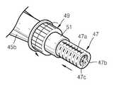
상기 가이더(45)에 끼워지는 카테터(55)는 도 11에 도시한 구성을 갖는다. 도 11을 참조하면, 상기 카테터(55)는, 길이방향으로 연장되고 그 선단부(도면상 하단부)에 풍선(27b)이 구비되어 있는 플렉시블튜브(27a)와, 상기 플렉시블튜브(27a)의 후단부(도면상 상단부)에 고정되는 리드스크류(47)와, 상기 리드스크류(47)에 고정되는 어뎁터(27c)와, 상기 어뎁터(27c)와 리드스크류(47)와 플렉시블튜브(27a)를 거쳐 풍선(27b)의 내부에 도달하는 가이드와이어(23)로 구성됨을 알 수 있다.The
상기 가이드와이어(23)의 후단부는 가이드와이어홀더(24)에 고정되어 있고, 가이드와이어홀더(24)는 어뎁터(27c)에 고정되어 있다. 상기 가이드와이어(23)는 리드스크류(47)와 플랙시블튜브(27a)의 내벽면으로부터 이격되어, 주입통로(27g)로 들어와 풍선(27b)을 향하는 유체의 유동을 방해하지 않는다.The rear end of the
한편, 상기 리드스크류(47)는 그 외주면에 수나사산(47e)이 형성되어 있는 원통형부재로서 그 중심축부에 관통로(도 8의 47c)가 형성되어 있다. 상기 관통로(47c)는 리드스크류(47)의 길이방향으로 연장된 통로로서, 일단부는 상기 어뎁터(27c)에 연통결합하고 타단부는 플렉시블튜브(27a)에 연통 결합한다. 연통결합이라 함은 그 내부의 통로가 상호 통교하도록 연결되는 결합을 의미한다.On the other hand, the
특히 상기 리드스크류(47)의 일단부 주연부에는 걸림슬릿(47d)이 마련되어 있다. 상기 걸림슬릿(47d)은 리드스크류(47)의 반지름방향 및 길이방향으로 개방되어 있는 홈으로서 가이드레일(45e)을 수용한다. 상기와 같이 걸림슬릿(47d)이 가이드레일(45e)에 걸려 있으므로, 리드스크류(47)는 길이방향으로 직선운동만 가능하고 축회전 하지는 못한다.In particular, a locking
또한 상기 리드스크류(47)의 주연부 일측에는 눈금부(47a)가 마련되어 있다. 상기 눈금부(47a)는 리드스크류의 해당부분을 기계가공하여 평면처리한 후 그 안에 눈금을 마킹한 부분이다. 상기와 같이 눈금부(47a)를 적용함으로써 풍선의 위치제어가 매우 정밀해진다.In addition, a
도 8은 상기 조절노브(49) 및 리드스크류(47)를 별도로 도시한 사시도이다.8 is a perspective view showing the
도시한 바와같이, 상기 조절노브(49)의 치합부(51)가 리드스크류(47)에 치합하고 있다. 또한 상기 치합부(51)의 아래로 눈금부(47a)가 지나고 있다. 상기 눈금부(47a)에 마킹된 눈금은, 조절노브(49)를 회전시킴에 따라 움직여 카테터의 움직임거리와 현재 위치를 정확하게 판단할 수 있게 한다.As shown, the
도면부호 47b는 암나사산이다. 상기 암나사산(47b)은 어뎁터(27c)와 나사 결합하는 부분이다. 어뎁터(27c)가 상기 암나사산(47b)에 결합함에 따라 어뎁터(27c)의 내부 통로는 관통로(47c)에 연통한다.
도 9는 상기 도 5에 도시한 벌룬시스템(41)의 단면도이다.9 is a cross-sectional view of the
도면을 참조하면, 상기 가이더(45)의 내부에 플렉시블튜브(27a)와 리드스크류(47)의 일부가 수용되어 있음을 알 수 있다. 상기 리드스크류(47)는 조절노브(49)의 치합부(51)에 치합됨과 아울러 가이드레일(45e)에 지지되어, 조절노브(49)의 회전에 따라 길이방향 즉 가이드파이프(45a)의 길이방향으로 직선운동한다.Referring to the drawings, it can be seen that a part of the
상기 리드스크류(47)가 가령 가이드파이프(45a) 측으로 이동하면, 플렉시블튜브(27a)와 가이드와이어(23)와 어뎁터(27c)와 풍선(27b)이 동시에 이동하며, 가이드파이프(45a) 하단부 내부에 대기하고 있던 풍선(도 10의 27b)이 가이드파이프(45a) 외부로 노출된다. 조절노브(49)를 반대방향으로 회전시키면, 카테터(55)가 후퇴하며 풍선(27b)이 가이드파이프(45a) 내부로 들어감은 물론이다.When the
도 10은 상기 도 5에 도시한 벌룬시스템(41)에서 가이드파이프에 내장되어 있는 플렉시블튜브 일부와 풍선을 도시한 도면이다.FIG. 10 is a view showing a part of a flexible tube and a balloon embedded in a guide pipe in the
도시한 바와같이, 상기 벌룬시스템(41)을 사용하지 않을 때에 풍선(27b)이 가이드파이프(45a)의 단부 내부에 대기하고 있다. 이 상태에서 조절노브(49)를 이용해 눈금부(47a)의 눈금을 확인하면서 풍선(27b)을 원하는 정도로 빼내어 척추체(11)내의 골절부위(13)를 들어올린다.As shown, the
상기한 구성을 갖는 본 실시예에 따른 벌룬시스템(41)을 사용하기 위해서는 먼저, 캐뉼러(43)를 척추체의 골절부위(도 1a의 13)를 향하도록 체내에 삽입한다.In order to use the
상기 캐뉼러(43)의 삽입이 완료된 후, 골절부위(13)의 내부에 풍선(27b)이 들어갈 공간을 확보하는 별도의 작업을 수행한다. 이 작업을 마친다음, 카테터(55)가 장착되어 있는 가이더(45)를 캐뉼러(43)에 삽입한다. 이는 상기 가이더(45)의 가이드파이프(45a)를 도 7에 도시한 바와같이 유도파이프(43a)에 단지 삽입하는 간단한 과정이다. 상기 유도파이프(43a)에 가이드파이프(45a)가 완전히 삽입되었다면, 바디(45b)의 끼움돌기(45c)를 고정홈(43c)에 끼워 고정시킨다.After the insertion of the
이어서, 상기 조절노브(49)를 조작하여 카테터(55)를 환부측으로 이동시켜 풍선(27b)을 골절부위(13)의 내부에 위치시킨 후, 어뎁터(27c)의 주사기결합부(27e)에 주사기(31)를 직접 또는 간접 연결한 후 유체를 주입한다.Subsequently, by operating the adjusting
상기 주사기로부터 주입된 유체는 주입통로(27g)와 리드스크류(47)와 플렉시블튜브(27a)를 통과해 풍선(27b)에 도달하여 풍선을 팽창시킨다. 풍선(27b)은 유체에 의해 팽창하며 골절부위(13)에 골시멘트를 주입할 공간을확보한다.The fluid injected from the syringe passes through the
상기 과정을 마친 후, 유체를 가압하던 압력을 제거하고 캐뉼러(43)로부터 가이더(45)를 빼낸 다음 골시멘트 주입과정을 이어간다.After completing the above process, the pressure that pressurized the fluid is removed, the
이상, 본 발명을 구체적인 실시예를 통하여 상세하게 설명하였으나, 본 발명은 상기 실시예에 한정하지 않고, 본 발명의 기술적 사상의 범위내에서 통상의 지식을 가진 자에 의하여 여러 가지 변형이 가능하다.While the present invention has been particularly shown and described with reference to exemplary embodiments thereof, it is to be understood that the invention is not limited to the disclosed exemplary embodiments, but, on the contrary, is intended to cover various modifications and equivalent arrangements included within the spirit and scope of the appended claims.
11:척추체 13:골절부위 15:골시멘트
17:골시멘트주입키트 19:벌룬시스템 23:가이드와이어
24:가이드와이어홀더 25:캐뉼라 25a:손잡이
25b:유도파이프 25c:입구 27:카테터
27a:플렉시블튜브 27b:풍선 27c:어뎁터
27e:주사기결합부 27f:홀더결합부 27g:주입통로
31:주사기 31a:주둥이 41:벌룬시스템
43:캐뉼러 43a:유도파이프 43b:손잡이
43c:고정홈 43d:가이드구멍 43e:바디수용부
45:가이더 45a:가이드파이프 45b:바디
45c:끼움돌기 45d:공간부 45e:가이드레일
45f:외주홈 47:리드스크류 47a:눈금부
47b:암나사산 47c:관통로 47d:걸림슬릿
47e:수나사산 49:조절노브(knob) 49a:환형돌기
51:치합부 55:카테터11: Spine body 13: Fracture site 15: Bone cement
17: bone cement injection kit 19: balloon system 23: guide wire
24: Guide wire holder 25:
25b: guide
27a:
27e:
31:
43:
43c: fixing
45:
45c: fitting
45f: Outer groove 47: Lead
47b:
47e: male thread 49: adjusting
51: a fitting part 55: catheter
Claims (7)
Translated fromKorean상기 가이더의 후단부에 구비되며 시술자에 의해 제어되는 조절노브; 및,
상기 가이더의 내부에 수용 지지되는 것으로서, 작동시 상기 골절부위 내에 위치된 상태로 팽창하여 골절부위 내에 공간을 확보하는 풍선과, 외부로부터 공급된 유체를 풍선으로 유도하여 풍선이 팽창되도록 하는 플렉시블튜브와, 상기 플렉시블튜브의 후단부에 고정되며 상기 조절노브의 움직임에 연동하여 플렉시블튜브를 길이방향으로 이동시키는 연동부재를 구비하는 카테터를 포함하는 것을 특징으로 하는 풍선 척추 성형술용 벌룬시스템.A guider, the tip of which reaches the fracture site through a cannula inserted into the body to face the fracture site of the vertebral body;
A control knob provided at the rear end of the guider and controlled by an operator; And,
It is accommodated and supported in the guider, the balloon is expanded in a state positioned in the fracture site during operation, the balloon to secure a space in the fracture site, and the flexible tube to inflate the fluid supplied from the outside to the balloon to expand the balloon; And a catheter which is fixed to the rear end of the flexible tube and has an interlocking member for moving the flexible tube in the longitudinal direction in association with the movement of the adjusting knob.
상기 연동부재는, 외주면에 수나사산이 형성되어 있는 원통형 부재로서 외부로부터 공급된 유체를 그 내부로 통과시켜 플렉시블튜브로 전달하는 리드스크류이고,
상기 조절노브는, 상기 가이더에, 상기 리드스크류를 중심축으로 하는 축회전이 가능하도록 지지된 상태로 상기 리드스크류에 치합하여, 시술자에 의해 회전시 리드스크류를 길이방향으로 직선운동시키는 것을 특징으로 하는 풍선 척추 성형술용 벌룬시스템.The method of claim 1,
The interlocking member is a cylindrical member having a male screw thread formed on an outer circumferential surface thereof and is a lead screw passing a fluid supplied from the outside into the flexible tube,
The adjusting knob is engaged with the lead screw in a state in which the guide screw is supported to enable axial rotation about the lead screw, and the lead screw linearly moves in the longitudinal direction when the operator rotates. Balloon balloon surgery for balloon surgery.
상기 가이더는;
길이방향으로 연장된 금속파이프로서 상기 캐뉼러의 내부로 슬라이딩 삽입되며 그 내부에 상기 풍선 및 플렉시블튜브를 수용하는 가이드파이프와, 상기 가이드파이프의 후단부에 고정되며 상기 리드스크류를 일부 수용하고, 상기 리드스크류와 치합한 조절노브를 회전 가능하게 지지하는 바디로 이루어지고,
상기 바디의 내부에는 조절노브의 회전시 리드스크류가 따라서 회전 하는 것을 차단하는 회전방지수단이 구비되는 것을 특징으로 하는 풍선 척추 성형술용 벌룬시스템.The method of claim 2,
The guider;
A guide pipe which slides into the interior of the cannula as a longitudinally extending metal pipe and accommodates the balloon and the flexible tube therein, and is fixed to a rear end of the guide pipe and partially accommodates the lead screw; It consists of a body that rotatably supports the adjustment knob in line with the lead screw,
The inside of the body balloon rotation balloon system, characterized in that the rotation prevention means for preventing the rotation of the lead screw according to the rotation of the adjustment knob is provided.
상기 리드스크류의 주연부 일부에는 하나 이상의 걸림슬릿이 형성되어 있고,
상기 회전방지수단은, 상기 바디의 내측부에 일체를 이루며 상기 리드스크류의 길이방향으로 연장된 것으로서, 상기 걸림슬릿에 끼워져 리드스크류의 직선운동을 가이드하는 가이드레일을 포함하는 것을 특징으로 하는 풍선 척추 성형술용 벌룬시스템.The method of claim 3,
One or more engaging slits are formed on a part of the periphery of the lead screw,
The anti-rotation means is formed integrally with the inner side of the body and extends in the longitudinal direction of the lead screw, the balloon spinal surgery, characterized in that it comprises a guide rail which is fitted to the engaging slit to guide the linear movement of the lead screw Dragon balloon system.
상기 연동부재에는 연동부재의 길이방향 이동 정도를 알 수 있게 하는 눈금부가 마련되어 있는 것을 특징으로 하는 풍선 척추 성형술용 벌룬시스템.5. The method according to any one of claims 1 to 4,
The interlocking member is a balloon system for a balloon chiroplasty, characterized in that provided with a scale to determine the longitudinal movement of the interlocking member.
상기 캐뉼러는,
상기 가이드파이프를 수용 지지하는 유도파이프와, 상기 유도파이프의 후단부에 고정되는 손잡이로 구성되며,
상기 캐뉼러의 손잡이와 바디에는, 시술시 상기 손잡이에 바디를 고정시키기 위한 고정수단이 마련된 것을 특징으로 하는 풍선 척추 성형술용 벌룬시스템.The method of claim 3,
The cannula is,
It consists of a guide pipe for receiving and supporting the guide pipe, a handle fixed to the rear end of the guide pipe,
The handle and the body of the cannula, the balloon system for balloon chiroplasty, characterized in that the fixing means for fixing the body to the handle during the procedure is provided.
상기 고정수단은,
상기 캐뉼러의 손잡이에 형성되어 있는 고정홈 또는 끼움돌기와,
상기 바디의 외측부에 형성되어 상기 고정홈 또는 끼움돌기와 착탈 가능하게 결합하는 끼움돌기 또는 고정홈을 포함하는 것을 특징으로 하는 풍선 척추 성형술용 벌룬시스템.The method according to claim 6,
Wherein,
Fixing grooves or fitting protrusions formed in the handle of the cannula,
Balloon system for balloon chiroplasty is formed on the outer side of the body comprising a fitting protrusion or fixing groove detachably coupled with the fixing groove or the fitting protrusion.
Priority Applications (1)
| Application Number | Priority Date | Filing Date | Title |
|---|---|---|---|
| KR1020110090199AKR101206525B1 (en) | 2011-09-06 | 2011-09-06 | Balloon system for Spinal Fractures |
Applications Claiming Priority (1)
| Application Number | Priority Date | Filing Date | Title |
|---|---|---|---|
| KR1020110090199AKR101206525B1 (en) | 2011-09-06 | 2011-09-06 | Balloon system for Spinal Fractures |
Publications (1)
| Publication Number | Publication Date |
|---|---|
| KR101206525B1true KR101206525B1 (en) | 2012-11-30 |
Family
ID=47565663
Family Applications (1)
| Application Number | Title | Priority Date | Filing Date |
|---|---|---|---|
| KR1020110090199AActiveKR101206525B1 (en) | 2011-09-06 | 2011-09-06 | Balloon system for Spinal Fractures |
Country Status (1)
| Country | Link |
|---|---|
| KR (1) | KR101206525B1 (en) |
Cited By (8)
| Publication number | Priority date | Publication date | Assignee | Title |
|---|---|---|---|---|
| JP2018057840A (en)* | 2016-10-07 | 2018-04-12 | カイフォン・ソシエテ・ア・レスポンサビリテ・リミテ | Surgical device and use method |
| CN109717910A (en)* | 2019-03-13 | 2019-05-07 | 霍建忠 | A kind of Lantern pyramidal support biopsy device |
| CN111166452A (en)* | 2020-03-28 | 2020-05-19 | 苏州爱得科技发展股份有限公司 | Vertebroplasty and Reconstruction System Type A |
| KR20200134086A (en)* | 2019-05-21 | 2020-12-01 | 사회복지법인 삼성생명공익재단 | Drainage catheter capable of expanding balloon |
| KR20210011635A (en) | 2019-07-23 | 2021-02-02 | 오인수 | Bone cement infusion device for percutaneous vertebroplasty |
| CN114767188A (en)* | 2022-03-24 | 2022-07-22 | 上海交通大学医学院附属新华医院 | Growth promoting device for lower cecum of esophagus |
| CN115227375A (en)* | 2022-07-29 | 2022-10-25 | 张英泽 | Bone cement injection device for vertebroplasty |
| CN115486804A (en)* | 2022-09-29 | 2022-12-20 | 武汉市九头鸟医疗仪器开发有限公司 | Disposable urinary bladder seminal vesicle scope |
Citations (4)
| Publication number | Priority date | Publication date | Assignee | Title |
|---|---|---|---|---|
| JP2002291896A (en) | 2001-03-29 | 2002-10-08 | Clinical Supply:Kk | Catheter with balloon |
| US6726691B2 (en) | 1998-08-14 | 2004-04-27 | Kyphon Inc. | Methods for treating fractured and/or diseased bone |
| KR100476972B1 (en) | 2003-07-18 | 2005-03-16 | (주)태연메디칼 | Cathter struction for balloon spinal correction |
| KR100787391B1 (en) | 2006-09-01 | 2007-12-21 | 안용철 | Balloon Catheter for Spinal Therapy |
- 2011
- 2011-09-06KRKR1020110090199Apatent/KR101206525B1/enactiveActive
Patent Citations (4)
| Publication number | Priority date | Publication date | Assignee | Title |
|---|---|---|---|---|
| US6726691B2 (en) | 1998-08-14 | 2004-04-27 | Kyphon Inc. | Methods for treating fractured and/or diseased bone |
| JP2002291896A (en) | 2001-03-29 | 2002-10-08 | Clinical Supply:Kk | Catheter with balloon |
| KR100476972B1 (en) | 2003-07-18 | 2005-03-16 | (주)태연메디칼 | Cathter struction for balloon spinal correction |
| KR100787391B1 (en) | 2006-09-01 | 2007-12-21 | 안용철 | Balloon Catheter for Spinal Therapy |
Cited By (11)
| Publication number | Priority date | Publication date | Assignee | Title |
|---|---|---|---|---|
| JP2018057840A (en)* | 2016-10-07 | 2018-04-12 | カイフォン・ソシエテ・ア・レスポンサビリテ・リミテ | Surgical device and use method |
| KR20180038972A (en)* | 2016-10-07 | 2018-04-17 | 키폰 에스에이알엘 | Surgical system and methods of use |
| KR102495037B1 (en) | 2016-10-07 | 2023-02-02 | 메드트로닉 홀딩 컴퍼니 에스에이알엘 | Surgical system and methods of use |
| CN109717910A (en)* | 2019-03-13 | 2019-05-07 | 霍建忠 | A kind of Lantern pyramidal support biopsy device |
| KR20200134086A (en)* | 2019-05-21 | 2020-12-01 | 사회복지법인 삼성생명공익재단 | Drainage catheter capable of expanding balloon |
| KR102222395B1 (en) | 2019-05-21 | 2021-03-03 | 사회복지법인 삼성생명공익재단 | Drainage catheter capable of expanding balloon |
| KR20210011635A (en) | 2019-07-23 | 2021-02-02 | 오인수 | Bone cement infusion device for percutaneous vertebroplasty |
| CN111166452A (en)* | 2020-03-28 | 2020-05-19 | 苏州爱得科技发展股份有限公司 | Vertebroplasty and Reconstruction System Type A |
| CN114767188A (en)* | 2022-03-24 | 2022-07-22 | 上海交通大学医学院附属新华医院 | Growth promoting device for lower cecum of esophagus |
| CN115227375A (en)* | 2022-07-29 | 2022-10-25 | 张英泽 | Bone cement injection device for vertebroplasty |
| CN115486804A (en)* | 2022-09-29 | 2022-12-20 | 武汉市九头鸟医疗仪器开发有限公司 | Disposable urinary bladder seminal vesicle scope |
Similar Documents
| Publication | Publication Date | Title |
|---|---|---|
| KR101206525B1 (en) | Balloon system for Spinal Fractures | |
| EP2919680B1 (en) | Multichannel cannula | |
| US11602375B2 (en) | Methods and devices for protecting catheter tips and stereotactic fixtures for microcatheters | |
| US20190083756A1 (en) | Deflation and removal of implantable medical devices | |
| KR100950990B1 (en) | Bone Therapy | |
| JP6371315B2 (en) | System, method and apparatus for reaming bone elements | |
| KR101164852B1 (en) | Balloon catheter | |
| US10398483B2 (en) | Multichannel cannula and methods for using same | |
| KR101760920B1 (en) | Multi needle with ease to regulate depth | |
| US10368932B2 (en) | Kyphoplasty device and method | |
| KR100950989B1 (en) | Device for transdermal delivery of bone filling material | |
| KR101598277B1 (en) | Catheter having direction control function of balloon | |
| KR20150002664A (en) | Release device for actuating a delivery catheter | |
| US20170189091A1 (en) | Multichannel cannula for kyphoplasty and method of use | |
| CN106687080A (en) | Syringe equipment | |
| CN106028984B (en) | Multichannel intubation and its application method | |
| ES2297061T3 (en) | CANULA FOR THE APPLICATION OF MEDICAL SUBSTANCES. | |
| KR101266967B1 (en) | A balloon catheter for use in a surgical operation for spine | |
| ITVR20080067A1 (en) | DEVICE FOR SURGICAL USE | |
| KR100568071B1 (en) | Bone Cement Infusion Device for Treatment of Osteoporotic Bone | |
| CN211583456U (en) | Device for directionally and continuously injecting bone cement | |
| KR200488786Y1 (en) | Medical tool for thread insertion | |
| JP2010099284A (en) | Bone prosthetic material injector |
Legal Events
| Date | Code | Title | Description |
|---|---|---|---|
| A201 | Request for examination | ||
| PA0109 | Patent application | St.27 status event code:A-0-1-A10-A12-nap-PA0109 | |
| PA0201 | Request for examination | St.27 status event code:A-1-2-D10-D11-exm-PA0201 | |
| E701 | Decision to grant or registration of patent right | ||
| PE0701 | Decision of registration | St.27 status event code:A-1-2-D10-D22-exm-PE0701 | |
| GRNT | Written decision to grant | ||
| PR0701 | Registration of establishment | St.27 status event code:A-2-4-F10-F11-exm-PR0701 | |
| PR1002 | Payment of registration fee | St.27 status event code:A-2-2-U10-U11-oth-PR1002 Fee payment year number:1 | |
| PG1601 | Publication of registration | St.27 status event code:A-4-4-Q10-Q13-nap-PG1601 | |
| R18-X000 | Changes to party contact information recorded | St.27 status event code:A-5-5-R10-R18-oth-X000 | |
| FPAY | Annual fee payment | Payment date:20150902 Year of fee payment:4 | |
| PR1001 | Payment of annual fee | St.27 status event code:A-4-4-U10-U11-oth-PR1001 Fee payment year number:4 | |
| PN2301 | Change of applicant | St.27 status event code:A-5-5-R10-R13-asn-PN2301 St.27 status event code:A-5-5-R10-R11-asn-PN2301 | |
| FPAY | Annual fee payment | Payment date:20161017 Year of fee payment:5 | |
| PR1001 | Payment of annual fee | St.27 status event code:A-4-4-U10-U11-oth-PR1001 Fee payment year number:5 | |
| P22-X000 | Classification modified | St.27 status event code:A-4-4-P10-P22-nap-X000 | |
| FPAY | Annual fee payment | Payment date:20170912 Year of fee payment:6 | |
| PR1001 | Payment of annual fee | St.27 status event code:A-4-4-U10-U11-oth-PR1001 Fee payment year number:6 | |
| PR1001 | Payment of annual fee | St.27 status event code:A-4-4-U10-U11-oth-PR1001 Fee payment year number:7 | |
| PN2301 | Change of applicant | St.27 status event code:A-5-5-R10-R13-asn-PN2301 St.27 status event code:A-5-5-R10-R11-asn-PN2301 | |
| FPAY | Annual fee payment | Payment date:20190916 Year of fee payment:8 | |
| PR1001 | Payment of annual fee | St.27 status event code:A-4-4-U10-U11-oth-PR1001 Fee payment year number:8 | |
| PR1001 | Payment of annual fee | St.27 status event code:A-4-4-U10-U11-oth-PR1001 Fee payment year number:9 | |
| PR1001 | Payment of annual fee | St.27 status event code:A-4-4-U10-U11-oth-PR1001 Fee payment year number:10 | |
| PR1001 | Payment of annual fee | St.27 status event code:A-4-4-U10-U11-oth-PR1001 Fee payment year number:11 | |
| PR1001 | Payment of annual fee | St.27 status event code:A-4-4-U10-U11-oth-PR1001 Fee payment year number:12 | |
| PR1001 | Payment of annual fee | St.27 status event code:A-4-4-U10-U11-oth-PR1001 Fee payment year number:13 | |
| PR1001 | Payment of annual fee | St.27 status event code:A-4-4-U10-U11-oth-PR1001 Fee payment year number:14 |