KR101205287B1 - Container base structure responsive to vacuum related forces - Google Patents
Container base structure responsive to vacuum related forcesDownload PDFInfo
- Publication number
- KR101205287B1 KR101205287B1KR1020077027634AKR20077027634AKR101205287B1KR 101205287 B1KR101205287 B1KR 101205287B1KR 1020077027634 AKR1020077027634 AKR 1020077027634AKR 20077027634 AKR20077027634 AKR 20077027634AKR 101205287 B1KR101205287 B1KR 101205287B1
- Authority
- KR
- South Korea
- Prior art keywords
- container
- base
- ring
- body portion
- wall thickness
- Prior art date
- Legal status (The legal status is an assumption and is not a legal conclusion. Google has not performed a legal analysis and makes no representation as to the accuracy of the status listed.)
- Expired - Fee Related
Links
Images


Classifications
- B—PERFORMING OPERATIONS; TRANSPORTING
- B65—CONVEYING; PACKING; STORING; HANDLING THIN OR FILAMENTARY MATERIAL
- B65D—CONTAINERS FOR STORAGE OR TRANSPORT OF ARTICLES OR MATERIALS, e.g. BAGS, BARRELS, BOTTLES, BOXES, CANS, CARTONS, CRATES, DRUMS, JARS, TANKS, HOPPERS, FORWARDING CONTAINERS; ACCESSORIES, CLOSURES, OR FITTINGS THEREFOR; PACKAGING ELEMENTS; PACKAGES
- B65D1/00—Rigid or semi-rigid containers having bodies formed in one piece, e.g. by casting metallic material, by moulding plastics, by blowing vitreous material, by throwing ceramic material, by moulding pulped fibrous material or by deep-drawing operations performed on sheet material
- B65D1/02—Bottles or similar containers with necks or like restricted apertures, designed for pouring contents
- B65D1/0223—Bottles or similar containers with necks or like restricted apertures, designed for pouring contents characterised by shape
- B65D1/0261—Bottom construction
- B65D1/0276—Bottom construction having a continuous contact surface, e.g. Champagne-type bottom
- B—PERFORMING OPERATIONS; TRANSPORTING
- B65—CONVEYING; PACKING; STORING; HANDLING THIN OR FILAMENTARY MATERIAL
- B65D—CONTAINERS FOR STORAGE OR TRANSPORT OF ARTICLES OR MATERIALS, e.g. BAGS, BARRELS, BOTTLES, BOXES, CANS, CARTONS, CRATES, DRUMS, JARS, TANKS, HOPPERS, FORWARDING CONTAINERS; ACCESSORIES, CLOSURES, OR FITTINGS THEREFOR; PACKAGING ELEMENTS; PACKAGES
- B65D79/00—Kinds or details of packages, not otherwise provided for
- B65D79/005—Packages having deformable parts for indicating or neutralizing internal pressure-variations by other means than venting
- B65D79/008—Packages having deformable parts for indicating or neutralizing internal pressure-variations by other means than venting the deformable part being located in a rigid or semi-rigid container, e.g. in bottles or jars
- B65D79/0081—Packages having deformable parts for indicating or neutralizing internal pressure-variations by other means than venting the deformable part being located in a rigid or semi-rigid container, e.g. in bottles or jars in the bottom part thereof
- Y—GENERAL TAGGING OF NEW TECHNOLOGICAL DEVELOPMENTS; GENERAL TAGGING OF CROSS-SECTIONAL TECHNOLOGIES SPANNING OVER SEVERAL SECTIONS OF THE IPC; TECHNICAL SUBJECTS COVERED BY FORMER USPC CROSS-REFERENCE ART COLLECTIONS [XRACs] AND DIGESTS
- Y10—TECHNICAL SUBJECTS COVERED BY FORMER USPC
- Y10T—TECHNICAL SUBJECTS COVERED BY FORMER US CLASSIFICATION
- Y10T428/00—Stock material or miscellaneous articles
- Y10T428/13—Hollow or container type article [e.g., tube, vase, etc.]
- Y10T428/1352—Polymer or resin containing [i.e., natural or synthetic]
Landscapes
- Engineering & Computer Science (AREA)
- Mechanical Engineering (AREA)
- Ceramic Engineering (AREA)
- Containers Having Bodies Formed In One Piece (AREA)
- Packages (AREA)
- Blow-Moulding Or Thermoforming Of Plastics Or The Like (AREA)
- Details Of Rigid Or Semi-Rigid Containers (AREA)
- Medical Preparation Storing Or Oral Administration Devices (AREA)
- Rigid Containers With Two Or More Constituent Elements (AREA)
- Moulds For Moulding Plastics Or The Like (AREA)
Abstract
Description
Translated fromKorean본 발명은 일반적으로 상품, 특히 액체 상품을 보관하는 플라스틱 용기에 관한 것이다. 더욱 구체적으로 본 발명은 용기의 다른 부분에서의 원하지 않는 변형없이 베이스에 의한 진공압의 상당한 흡수를 가능하게 하는 베이스 구조를 지니는 패널없는(panel-less) 플라스틱 용기에 관한 것이다.The present invention relates generally to plastic containers for storing goods, in particular liquid goods. More specifically, the present invention relates to a panel-less plastic container having a base structure that allows for significant absorption of vacuum pressure by the base without unwanted deformations in other parts of the container.
환경 및 다른 이슈의 결과로서, 과거 유리 용기에 제공되었던 수많은 상품들이 현재는 플라스틱 용기, 더 구체적으로는 폴리에스테르, 좀더 구체적으로는 PET(polyethylene terephtalate) 용기들이 사용되고 있다. 소비자들 뿐만 아니라 제조업자와 충진자(filler)도 PET용기가 가볍고, 저가이며, 재생가능하고 대량으로 제조가능하다는 것을 인식하고 있다.As a result of environmental and other issues, a number of products that have been offered in glass containers in the past are now being used in plastic containers, more specifically in polyester, more specifically in polyethylene terephtalate (PET) containers. Manufacturers and fillers, as well as consumers, recognize that PET containers are light, inexpensive, renewable and can be manufactured in large quantities.
제조업자들은 현재 음료수와 같은 다양한 액체 상품들에 PET 용기를 제공한다. 쥬스와 아이소토닉(isotonic)과 같은 이런 액체 상품들은 종종 액체 상품이 상승된 온도, 통상적으로 68℃에서 96℃ 그리고 대개 약 85℃인 동안에 용기에 채워진다. 이런 방식으로 패키지 되었을 때, 액체 상품의 고온은 액체를 충진(filling)할 때 용기를 살균한다. 용기 산업에서는 이 공정이 고온 충진 공정으 로 불리며, 위 공정을 견디도록 설계된 용기들은 고온 충진 또는 열 경화된 용기라고 불린다.Manufacturers currently provide PET containers for various liquid products, such as beverages. Such liquid products, such as juices and isotonic, are often filled in containers while the liquid product is at elevated temperatures, typically 68 ° C. to 96 ° C. and usually about 85 ° C. When packaged in this way, the high temperature of the liquid product sterilizes the container when filling the liquid. In the container industry, this process is called a hot fill process and containers designed to withstand the above process are called hot filled or thermoset containers.
고온 충진은 높은 산성물을 가지는 상품을 위해 적당한 공정이지, 높지 않은 산성물을 가지는 상품에는 일반적으로 적당하지 않다. 그러나 산성이 높지 않은 상품은 다른 방식으로 처리되어야 한다. 그럼에도 불구하고, 높지 않은 산성 상품의 제조업자와 충진자들 역시 그들의 상품을 PET에 제공하기를 바란다. 산성이 높지 않은 상품에 대해서 파스퇴르화(pasteurization)와 레토르트(retort)는 선호되는 살균 공정이다. 열 경화된 용기는 파스퇴르화와 레토르트에 필요한 온도와 시간 요구를 견딜 수 없기 때문에, 파스퇴르화와 레토르트는 PET 용기의 제조업자들을 어렵게 한다.Hot filling is a suitable process for products with high acidity, but generally not for products with high acidity. However, non-acidic commodities must be disposed of in a different way. Nevertheless, manufacturers and fillers of non-high acid products also want to provide their products to PET. Pasteurization and retort are the preferred sterilization processes for non-acidic commodities. Pasteurized and retort makes manufacturers of PET containers difficult because heat cured containers cannot withstand the temperature and time requirements for pasteurization and retort.
파스퇴르화와 레토르트는 모두 용기에 내용물이 채워진 후 용기의 내용물을 살균하거나 요리하는데 필요한 공정이다. 양 공정들은 특정 온도로 용기의 내용물들을 가열하는 단계를 포함하는데, 보통 약 70℃ 이상으로 특정길이의 시간(20-60분)동안 가열한다. 레토르트는 용기에 외부로 압력을 가하기 때문에 더 높은 온도를 이용한다는 점에서 파스퇴르화와 다르다. 또한, 용기 내부의 압력을 견디기 위하여 레토르트는 용기의 외측으로 증가된 압력을 가한다. 용기의 외부에 가해지는 압력은 필수적인데, 이는 고온의 수조가 종종 사용되고 과압(overpressure)이 용기의 내용물의 액체 뿐만 아니라 액체 형태의 물을 각각의 끓는점 온도 이상으로 유지시키기 때문이다.Pasteurization and retort are both processes required to sterilize or cook the contents of the container after it has been filled. Both processes involve heating the contents of the vessel to a specific temperature, which is usually heated to a specified length of time (20-60 minutes) above about 70 ° C. Retort differs from pasteurization in that it uses a higher temperature because it pressures the vessel outwards. In addition, the retort exerts increased pressure outside the vessel to withstand the pressure inside the vessel. The pressure exerted on the outside of the vessel is essential because hot baths are often used and overpressure keeps the liquid in the vessel's contents as well as the liquid form of water above their respective boiling point temperatures.
PET는 결정화된 폴리머(crystallizable polymer)이다. 이것은 PET가 비정질 (amorphous)또는 반 결정화된 형태(semi-crystalline form)에서 사용할 수 있다는 것을 의미한다. 그 물질의 일체성을 유지하는 PET 용기의 능력은 PET 용기의 "결정도(crystallinity)"라고도 알려진 결정화된 형태에서의 PET 용기의 백분율과 관련된다. 결정도 백분율은 다음과 같은 방정식에 의하여 부피비로서 특징지어진다.PET is a crystallizable polymer. This means that PET can be used in amorphous or semi-crystalline form. The ability of a PET container to maintain the integrity of the material is related to the percentage of PET container in crystallized form, also known as the "crystallinity" of the PET container. The crystallinity percentage is characterized as volume ratio by the following equation.

여기서, ρ는 PET 물질의 밀도이고, ρa는 순수한 비정질 PET 물질(1.333 g/cc)이며, ρc는 순수 결정화된(crystalline) 물질(1.455 g/cc)이다.Where ρ is the density of the PET material, ρa is the pure amorphous PET material (1.333 g / cc), and ρc is the pure crystalline material (1.455 g / cc).
용기 제조자들은 용기의 PET 폴리머 결정도를 증가시키기 위하여 기계적인 공정과 열 공정을 사용한다. 기계적인 공정은 인장 경화(strain hardening)를 달성하기 위하여 비정질 물질로 순응시키는 단계를 포함한다. 이 공정은 공통적으로 길이방향 축을 따라 PET의 초기형태로 늘리는 단계와 PET 용기를 형성하기 위하여 횡 또는 반경방향 축을 따라서 PET의 초기형태로 팽창하는 단계를 포함한다. 조합은 용기의 분자 구조의 양축 지향(biaxial orientation)이라고 알려진 것을 촉진한다. PET 용기의 제조업자들은 용기 측벽의 결정도를 20% 정도 가지는 PET 용기를 생산하기 위하여 현재 기계적인 공정을 사용한다.Container manufacturers use mechanical and thermal processes to increase the PET polymer crystallinity of the container. The mechanical process includes the step of acclimatizing with an amorphous material to achieve strain hardening. This process commonly includes stretching to the initial form of PET along the longitudinal axis and expanding to the initial form of PET along the transverse or radial axis to form the PET container. The combination facilitates what is known as the biaxial orientation of the molecular structure of the vessel. Manufacturers of PET containers currently use mechanical processes to produce PET containers with a 20% crystallinity of the container sidewalls.
열 공정은 크리스탈 성장을 촉진하기 위하여 비정질 또는 반 결정화된 것 중의 하나인 물질을 가열하는 단계를 포함한다. 비정질 물질에서, PET 물질의 열 공 정은 광의 투과를 간섭하는 구과(球顆) 형태(spherulitic morphology)를 초래한다. 다시 말하면, 결과적인 결정화된 물질은 불투명하고, 따라서 일반적으로 바람직하지 않다. 그러나, 기계적인 공정 이후에 사용되면, 양축 분자 지향을 가지는 용기의 그 부분들에 대해서 열 공정은 더 높은 결정도와 뛰어난 투명도를 초래한다. 열 경화라고 알려진 지향된 PET 용기의 열 공정은 통상적으로 약 121℃-l77℃의 온도로 가열된 주형(mold)에 대하여 PET 초기형태로 블로우 몰딩하는 단계와 약 2초 내지 5초 동안 가열된 주형에 대하여 블로우된 용기를 유지하는 단계를 포함한다. 약 85℃에서 고온으로 채워져야 하는 PET 쥬스 병의 제조업자들은 25-30%범위의 전체 결정도를 가지는 PET 병들을 생산하기 위하여 현재 열 경화를 사용한다.The thermal process includes heating a material that is either amorphous or semi-crystallized to promote crystal growth. In amorphous materials, the thermal process of PET materials results in spherulitic morphology that interferes with the transmission of light. In other words, the resulting crystallized material is opaque and therefore generally undesirable. However, if used after a mechanical process, the thermal process results in higher crystallinity and excellent transparency for those parts of the container having biaxial molecular orientation. The thermal process of a directed PET container known as thermal curing typically involves blow molding into a PET initial form for a mold heated to a temperature of about 121 ° C.-77 ° C. and a heated mold for about 2 to 5 seconds. Maintaining the blown container against. Manufacturers of PET juice bottles, which must be filled at high temperatures at about 85 ° C., currently use thermal curing to produce PET bottles with a total crystallinity in the range of 25-30%.
고온으로 채워진 뒤, 열 경화 용기들은 마개가 씌워지고 대략 5분동안 충진 온도로 잔류된다. 그리고 나서 용기들은 제품과 함께 라벨링, 패키징과 배송 작업으로 이송되기 전에 급속히 냉각된다. 냉각됨으로써 용기 내의 액체의 부피는 줄어든다. 이 제품 수축 현상은 용기내의 진공 생성을 초래한다. 일반적으로 용기 내의 진공압은 대기압(즉, 759mmHg ~ 380mmHg) 보다 작은 1-380mm/Hg 범위이다. 이런 진공압이 제어되지 못하거나 수용되지 못하면, 이런 진공압은 용기의 변형을 초래하게 되어 미적으로 받아들여질 수 없는 용기가 되거나 불안정한 용기가 되게 만든다. 전형적으로, 산업에서는 측벽의 구조 또는 진공 패널을 가지고 진공 관련 압력을 수용한다. 진공 패널들은 일반적으로 용기 측벽의 원하지 않는 변형을 제거하기 위하여 제어된 방식으로 진공압하에서 안쪽으로 찌그러진다.After filling at high temperature, the thermosetting containers are capped and left at fill temperature for approximately 5 minutes. The containers are then rapidly cooled with the product before being transported for labeling, packaging and shipping operations. By cooling, the volume of liquid in the vessel is reduced. This product shrinkage results in the creation of a vacuum in the container. In general, the vacuum pressure in the vessel is in the range of 1-380 mm / Hg less than atmospheric pressure (ie, 759 mmHg to 380 mmHg). If this vacuum pressure is uncontrolled or unacceptable, it will cause the container to deform, resulting in an aesthetically unacceptable container or an unstable container. Typically, the industry has a structure of sidewalls or vacuum panels to accommodate vacuum related pressures. Vacuum panels are generally crushed inwards under vacuum pressure in a controlled manner to remove unwanted deformation of the container sidewalls.
진공 패널이 용기가 고온 충진 과정의 엄격함을 지탱하도록 허용하는 반면, 그것들은 몇가지 제한과 단점을 제공한다. 첫째, 진공 패널은 유리같은 매끄러운 외관을 만들지 않는다. 둘째, 패키저(packager)는 보통 감기는 랩 또는 슬리브 라벨을 진공 패널위로 용기에 부착한다. 가끔, 측벽과 진공 패널에 있는 이러한 라벨의 외관은 라벨이 주름지거나 매끄럽지 않다. 뿐만 아니라, 용기를 잡는 사람은 라벨 아래로 진공 패널을 일반적으로 느끼며, 종종 다양한 패널의 균열과 요부로 라벨을 민다.While vacuum panels allow the vessels to withstand the rigors of the hot filling process, they present some limitations and disadvantages. First, vacuum panels do not create a glassy appearance. Second, a packager attaches a wrap wrap or sleeve label, usually wrapped over the vacuum panel, to the container. Occasionally, the appearance of these labels on the sidewalls and the vacuum panel is not wrinkled or smooth. In addition, the holder of the container generally feels the vacuum panel under the label and often labels it with various panel cracks and recesses.
뿐만 아니라 진공압으로부터 초래되는 용기의 변형을 조절하는 것을 돕기 위하여 섬세한 개선은 용기 측벽에 핀치 그립 기하구조(pinch grip geometry)의 사용을 하도록 하여 왔다. 그러나, 진공 패널에 관하여 핀치 그립 기하구조에도 유사한 제한과 단점이 존재한다.In addition, minor improvements have been made to the use of pinch grip geometry on the container sidewalls to help control the deformation of the vessel resulting from vacuum pressure. However, similar limitations and disadvantages exist with the pinch grip geometry with respect to vacuum panels.
고온 충진 플라스틱 용기가 진공을 수용하는 구조적 특징을 갖지 않고도 상기 목적을 달성하기 위한 또 다른 방법은 질소 주입 기술의 사용이다. Another method for achieving this object without the high temperature filled plastic container having the structural features of accommodating vacuum is the use of nitrogen injection techniques.
그러나 이 기술을 사용할 때의 한가지 단점은 현재의 기술로 이룰 수 있는 최소한의 라인 속도는 분당 대략 200개의 용기에 제한된다는 점이다. 그 정도의 느린 라인 속도는 거의 허용될 수 없다. 뿐만 아니라, 주입의 일관성은 효율적인 작업을 이루기 위한 기술적인 수준에 도달하지 못하고 있다.However, one disadvantage of using this technique is that the minimum line speed achievable with current technology is limited to approximately 200 vessels per minute. That slow line speed is hardly acceptable. In addition, the consistency of injection has not reached the technical level to achieve efficient work.
따라서, 매끄럽고 유리와 같은 외관을 가질 수 있도록 실질적인 기하구조없이 측벽을 가지는 유리 용기의 외관을 흉내내는 고온의 충진에서 초래되는 진공압을 수용할 수 있는 개선된 용기의 필요성이 존재한다. 따라서, 발명의 목적은 그러한 용기를 제공하는 것이다.Accordingly, there is a need for an improved container capable of accommodating the vacuum pressure resulting from high temperature filling that mimics the appearance of a glass container having a sidewall without a substantial geometry so that it can have a smooth, glassy appearance. Therefore, it is an object of the invention to provide such a container.
따라서, 본 발명은 고온 충진되고 주위 온도로 냉각된 이후의 어떤 후속의 취급 동안에 심미감과 기계적인 일체성을 유지하는 플라스틱 용기를 제공하며, 이는 용기의 다른 부분에서 원하지 않는 변형없이 베이스에 의해 진공압의 실질적인 흡수를 허용하는 베이스 구조를 가짐으로써 달성가능하다. Thus, the present invention provides a plastic container that maintains aesthetics and mechanical integrity during any subsequent handling after hot filling and cooling to ambient temperature, which is vacuum pressured by the base without unwanted deformation in other parts of the container. It is achievable by having a base structure that allows substantial absorption of.
유리 용기에서, 용기는 움직이지 않고, 그 구조는 모든 압력과 힘들을 제한해야 한다. 가방 용기에서 용기는 쉽게 이동하고 제품에 맞게 순응한다. 본 발명은 다소 세련된 것으로, 움직이는 영역과 움직이지 않는 영역을 제공한다. 궁극적으로, 본 발명의 플라스틱 용기의 베이스부가 움직이고 변형된 후에, 용기의 나머지 전체 구조는 부서지지 않고도 모든 예상된 추가적인 압력이 힘들을 제한한다.In glass containers, the container does not move, and its structure must limit all pressures and forces. In the bag container, the container is easily moved and adapted to the product. The present invention is somewhat refined, providing moving and non-moving regions. Ultimately, after the base portion of the plastic container of the present invention is moved and deformed, the rest of the overall structure of the container limits all expected additional pressure without breaking.
본 발명은 상부, 본체부 또는 측벽부 및 베이스를 가지는 플라스틱 용기를 포한한다. 상부는 용기의 주둥이를 정의하는 개구를 포함한다. 본체부는 상부에서 베이스까지 연장된다. 베이스는 중앙 푸쉬업(pushup)과 반전 링에 의하여 적어도 부분적으로 정의되는 중앙부를 포함한다. 푸쉬업은 일반적으로 뿔잘린 원추형 단면을 가지며, 반전 링은 일반적으로 S자형 기하구조의 단면을 가진다.The present invention encompasses a plastic container having a top, a body portion or a side wall portion and a base. The upper part includes an opening defining the spout of the container. The body portion extends from the top to the base. The base includes a central portion defined at least in part by a central pushup and a reversal ring. Push-ups generally have a truncated conical cross section and inverted rings generally have a cross-section of an S-shaped geometry.
본 발명의 추가적인 이익과 장점은 이하 설명하는 바람직한 실시예와 추가된 청구항을 첨부된 도면과 함께 고려하는 것으로부터 본 발명이 속하는 기술분야에서 통상의 지식을 가진자에게 명백해질 것이다.Further advantages and advantages of the present invention will become apparent to those skilled in the art from consideration of the preferred embodiments described below and the appended claims in conjunction with the accompanying drawings.
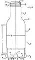
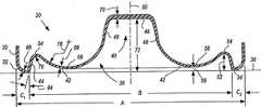
도 1은 본 발명에 따른 플라스틱 용기의 측면도로서, 용기는 성형되고 비어 있는 상태이다.1 is a side view of a plastic container according to the present invention, in which the container is molded and empty.
도 2는 본 발명에 따른 플라스틱 용기의 측면도로서, 용기는 채워지고 시일링된 상태이다.Figure 2 is a side view of a plastic container according to the present invention in which the container is filled and sealed.
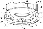
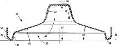
도 3은 도 1의 플라스틱 용기의 바닥 부분의 사시도이다.3 is a perspective view of a bottom portion of the plastic container of FIG. 1.
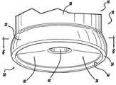
도 4는 도 2의 플라스틱 용기의 바닥 부분의 사시도이다.4 is a perspective view of a bottom portion of the plastic container of FIG. 2.
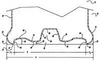
도 5는 도 3의 5-5라인을 따라 절취하였을 때의 플라스틱 용기의 단면도이다.5 is a cross-sectional view of the plastic container when taken along line 5-5 of FIG.
도 6은 도 4의 6-6라인을 따라 절취하였을 때의 플라스틱 용기의 단면도이다.6 is a cross-sectional view of the plastic container when taken along line 6-6 of FIG.
도 7은 도 5와 같은 플라스틱 용기의 단면도로서, 다른 실시예를 보여준다.FIG. 7 is a cross-sectional view of the plastic container as shown in FIG. 5, showing another embodiment.
도 8은 도 6과 같은 플라스틱 용기의 단면도로서, 다른 실시예를 보여준다.8 is a cross-sectional view of the plastic container as shown in FIG. 6, showing another embodiment.
도 9는 또 다른 실시예의 플라스틱 용기 바닥 부분의 사시도로서, 용기는 성형되고 비어있는 상태이다.9 is a perspective view of a plastic container bottom portion of another embodiment, in which the container is molded and empty.
도 10은 도 9의 10-10 라인을 따라 절개한 플라스틱 용기의 단면도이다.10 is a cross-sectional view of the plastic container taken along line 10-10 of FIG.
도 11은 도 9에 도시된 플라스틱 용기의 바닥 부분의 사시도로서, 용기는 채워지고 시일링된 상태이다.FIG. 11 is a perspective view of the bottom portion of the plastic container shown in FIG. 9 with the container filled and sealed.
도 12는 도 11의 12-12 라인을 따라 절개한 플라스틱 용기의 단면도이다.12 is a cross-sectional view of the plastic container taken along line 12-12 of FIG.
바람직한 실시예의 다음 기술은 본질적으로 단지 예시에 불과한 것이며, 결코 발명 또는 그 적용이나 용도를 제한하려는 것은 아니다.The following description of the preferred embodiments is merely exemplary in nature and is in no way intended to limit the invention or its application or use.
상기 기술된 바와 같이, 열 경화 용기내에서 내용물의 냉각 동안에 진공 관련된 힘을 수용하기 위하여 용기는 그 측벽 주위에 일련의 진공 패널 또는 핀치 그립을 지니고 있다. 진공 패널과 핀치 그립은 진공 관련된 힘의 영향하에 내측으로 변형되고 용기의 원하지 않는 다른 부분의 변형을 방지한다. 그러나, 진공 패널과 핀치 그립을 가진 용기의 측벽은 매끄럽거나 유리와 같지 못하고, 겹쳐지는 라벨은 주름지고 매끄럽지 못하며 최종 수요자는 용기를 잡고 집어 올릴 때 라벨의 아래로 진공 패널과 핀치 그립을 느낄 수 있다.As described above, the container has a series of vacuum panels or pinch grips around its sidewalls to accommodate vacuum-related forces during cooling of the contents in the thermosetting container. The vacuum panel and pinch grip deform inwards under the influence of vacuum-related forces and prevent deformation of other undesired portions of the container. However, the sidewalls of the container with vacuum panels and pinch grips are not smooth or glassy, the overlapping labels are not wrinkled or smooth and the end consumer can feel the vacuum panel and pinch grips under the label as they grab and pick up the container. have.
진공 패널 없는 용기에서 용기의 잔류물내에서의 조절된 변형(예를 들면, 베이스 또는 닫힘부에서)과 진공 저항이 요구된다. 따라서, 본 발명은 용기의 잔류물내에서의 강성 구조(예를 들면, 내부 진공에 대항하는)를 유지하면서 베이스부를 쉽게 움직이고 변형되도록 하는 플라스틱 용기를 제공한다. 예를 들면, 20온스(oz.)의 플라스틱 용기에서, 용기는 대략 20~24cc의 부피 변화를 수용할 수 있어야 한다. 본 발명의 플라스틱 용기에서, 베이스부는 이러한 요구조건(예를 들면, 대략 13cc)의 대다수를 수용한다. 플라스틱 용기의 나머지 부분은 쉽게 인식할 수 있는 변형 없이도 이 부피 변화의 나머지를 쉽게 수용할 수 있다.In a vessel without a vacuum panel, a controlled deformation (eg, at the base or the closure) and the vacuum resistance in the residue of the vessel are required. Accordingly, the present invention provides a plastic container that allows the base portion to be easily moved and deformed while maintaining a rigid structure (eg, against internal vacuum) within the residue of the container. For example, in a 20 oz. Plastic container, the container should be able to accommodate a volume change of approximately 20-24 cc. In the plastic container of the present invention, the base portion accommodates the majority of these requirements (eg, approximately 13 cc). The rest of the plastic container can easily accommodate the remainder of this volume change without a readily recognizable deformation.
도 1 및 도 2에 도시된 바와 같이, 본 발명의 플라스틱 용기(10)는 마무리부(12), 목 또는 연장된 목(14), 어깨 영역(shoulder region, 16), 본체부(18) 및 베이스(20)를 포함한다. 당업자는 목(14)이 매우 짧은 높이, 즉 도면에 도시된 바와 같이 마무리부(12) 또는 연장된 목으로부터 마무리부(12)와 어깨 영역 사이에서 연장하는 짧은 연장부가 된다는 것을 이해할 수 있다. 플라스틱 용기(10)는 특히 고온 충진과 같은 열 공정 동안에 물품을 보관하기 위하여 설계되었다. 고온 충진 병에 적용하는 경우, 일반적으로 용기(10)에 대략 68℃ 내지 96℃ 사이의 상승된 온도에서 액체나 물질이 채워지고, 냉각되기 전에 마개(28)로 용기가 밀봉된다. 밀봉된 용기(10)가 냉각됨에 따라, 약간의 진공 또는 부압(negative pressure)이 내부에 형성되어 용기(10) 특히 베이스(20)의 형상을 변화되게 한다. 뿐만 아니라, 플라스틱 용기(10)는 다른 고온 파스퇴르화 또는 레토르트 충진 공정 또는 다른 열 공정들에 적합할 수 있다.As shown in FIGS. 1 and 2, the
본 발명의 플라스틱 용기(10)는 블로우 몰딩 되고, 단층 또는 다층 물질로부터 단일 구조를 가진 단일 양축으로 지향된 용기이다. 고온 충진 가능한 플라스틱 용기(10)를 제조하는 잘 알려진 연신 성형(stretch-molding), 열 경화 공정은 일반적으로 폴리에틸렌 테레프탈레이트(PET)와 같은 폴리에스터 물질의 예형태(preform)의 제조를 포함한다.(미도시) 폴리에스터 물질의 예형태는 용기 높이의 대략 50%의 길이와 일반적으로 원통형 단면을 가진 테스트 튜브와 유사한 당업자에게 잘 알려진 형상을 가진다. 기계(미도시)는 대략 88℃ 내지 121℃ 사이의 온도로 가열된 예형태를 플라스틱 용기(10)와 유사한 형상을 가지는 주형의 캐비티(미도시) 내로 위치시킨다. 주형 캐비티(cavity)는 대략 121℃ 내지 177℃ 사이의 온도로 가열된다. 연장 봉 장치(미도시)는 주형 캐비티내에 있는 가열된 예형태를 용기의 대략적인 길이만큼 연장함으로써 일반적으로 중앙의 길이 방향 축(50)에 대응하는 축방향으로 폴리에스터 물질을 분자적으로 지향(molecularly orient)시킨다. 연장 봉이 예형태를 연장하는 동안, 2.07MPa 내지 4.14MPa 사이의 압력을 가진 공기는 축방향으로 예형태를 연장하고 원주 방향 또는 후프(hoop) 방향으로 예형태를 확장시키는 것을 도움으로써, 폴리에스터 물질을 주형 캐비티의 형상에 실질적으로 맞추고 더 나아가 축 방향과 일반적으로 수직한 방향으로 폴리에스터 물질을 분자적으로 지향시킨다. 그럼으로써 대부분의 용기에서 폴리에스터 물질의 양축 분자 지향성을 가지게 한다. 전형적으로 마무리부(12)와 베이스(20)의 서브부 내의 물질은 실질적으로 분자적으로 지향되지 않는다. 압력을 가진 공기는 주형 캐비티로부터 용기를 제거하기 전에 대략 2초 내지 5초 기간 동안 주형 캐비티에 대하여 대개 분자적으로 양축 지향된 폴리에스터 물질을 가진다. 베이스(20)내에서 적당한 물질 분포를 달성하기 위하여, 발명자들은 여기에 참조로서 포함된 미국 특허 제6,277,321호가 가르침을 제공하는 바와 같이 실질적으로 추가적인 연신 성형 공정을 채용한다.The
이와 달리, 플라스틱 용기(10)는 다른 방법으로 형성될 수도 있고, 예를 들면, PEN(polyethylene napthalate)과 PET/PEN 혼합 또는 공중합체(copolymer) 및 다양한 다층 구조들이 플라스틱 용기의 제조에 적합할 수 있다. 기술분야에 속하는 통상의 지식을 가진 자들은 플라스틱 용기(10)의 제조 방법의 대안을 쉽게 이해할 것이다.Alternatively, the
플라스틱 용기(10)의 마무리부(12)는 개구 또는 주둥이(22)를 한정하는 부분, 나사산 영역(24)과 지지 링(26)을 포함한다. 개구(22)는, 나사산 영역(24)이 유사하게 나사산이 형성된 마개 또는 캡(28)의 부착을 위한 수단을 제공하는 동안 플라스틱 용기(10)가 물품을 수용할 수 있도록 해준다.(도 2) 대체물은 플라스틱 용기(10)의 마무리부(12)를 맞물리게 하는 다른 적당한 장치를 포함할 수 있다. 따라서, 마개 또는 캡(28)은 바람직하게 플라스틱 용기(10)에 밀폐를 제공하기 위하여 마무리부(12)와 맞물리게 하는 역할을 한다. 마개 또는 캡(28)은 바람직하게는 고온의 파스퇴르화 또는 레토르트를 포함하여 후속하는 열공정에 적합하고 마개 산업에 전통적인 플라스틱 또는 금속 물질로 만들어진다. 지지 링(26)은 제조의 여러 단계들 및 그것을 통하여 예형태(플라스틱 용기(10)의 전구체)를 운반하고 그 위치를 잡게하는 데 사용될 수 있다. 예를 들면, 예형태는 지지 링(26)에 의하여 이동될 수 있고, 지지 링(26)은 주형에서 예형태를 위치시키는 것을 돕는 데 사용되거나 최종 수요자들이 일단 제조된 플라스틱 용기(10)를 이동시키는 데 사용될 수 있다.The
플라스틱 용기(10)의 연장된 목(14)은 플라스틱 용기(10)에 요구되는 부피를 수용할 수 있게 해 준다. 어깨 영역(16)은 연장된 목(14)과 일체로 형성되며 연장된 목으로부터 아래방향으로 연장된다. 어깨 영역(16)은 합쳐지고 연장된 목(14)과 본체부(18) 사이를 연결해준다. 본체부(18)는 어깨 영역(16)으로부터 베이스(20)까지 아래로 연장되며, 측벽(30)을 포함한다. 용기(10) 베이스(20)의 특정한 구조로 인하여, 열 경화된 용기(10)의 측벽(30)은 진공 패널 또는 핀치 그립을 반드시 필요로 하지는 않고, 그럼으로써 전체적으로 매끄럽고 유리와 같다. 상당히 가벼운 용기는 베이스(20)를 따라 진공 패널, 립(ribbing) 및/또는 핀치 그립을 갖는 측벽을 포함할 수도 있다.The
플라스틱 용기(10)의 베이스(20)는 전체적으로 본체부(18)로부터 내측으로 연장되며, 일반적으로 돌출 가장자리(chime, 32), 접촉 링(34) 및 중앙부(36)를 포함한다. 도 5, 6, 7, 8, 10 및 12에 도시된 바와 같이, 접촉 링(34)은 연속적으로 용기(10)를 지지하는 지지 표면(38)을 접촉하는 베이스부(20) 그 자체이다. 그러한 것으로서, 접촉 링(34)은 베이스(20)를 연속적으로 또는 간헐적으로 둘러싸는 접촉 선 또는 평면일 수 있다. 베이스(20)는 연장된 목(14), 어깨 영역(16) 및 본체부(18)과 함께 물품을 보관하기 위하여 플라스틱 용기(10)의 바닥부를 닫는 역할을 한다.The
플라스틱 용기(10)는 상기 언급된 공정 또는 다른 전통적인 열 경화 공정에 따라 바람직하게 열 경화된다. 용기(10)의 본체부(18)에서 진공 패널과 핀치 그립을 없앨 수 있도록 하면서도 진공 관련된 힘을 수용하기 위하여 본 발명의 베이스(20)는 새롭고 진보성있는 구조를 채택한다. 일반적으로, 베이스(20)의 중앙부(36)는 중앙 푸쉬업(pushup, 40)과 반전 링(42)을 가진다. 반전 링(42)은 상부(54) 및 하부(58)를 포함한다. 반전 링(42)은 일반적으로 "S"자 형의 단면 형상을 가진다.(도 5, 7, 10 참고) 또한, 베이스(20)는 반전 링(42)과 접촉 링(34) 사이의 연결부를 형성하는 에지(44) 또는 직립한 외주를 포함한다.The
도 1 내지 8, 10 및 12에 도시된 바와 같이, 중앙 푸쉬업(40)은, 단면으로 보았을 때, 일반적으로 지지 표면(38)에 실질적으로 평행한 꼭대기 면(46)을 가지는 뿔 잘린 원추형이다. 측 평면(48)들은 단면상에서 일반적으로 평면이며, 용기(10)의 중앙 길이 방향을 향하여 위쪽으로 기울어져 있다. 중앙 푸쉬업(40), 즉 뿔 잘린 원추형의 정확한 형상은 다양한 설계 기준에 따라서 크게 변화될 수 있다. 그러나, 대체로, 중앙 푸쉬업(40)의 전체적인 직경은 베이스(20)의 전체 직경의 최대 30%이다. 중앙 푸쉬업(40)은 전체적으로 예형태의 게이트가 주형에서 포획되는 부분이다. 실질적으로 분자적으로 방향성이 없는 폴리머 물질을 포함하는 베이스(20)의 서브부는 꼭대기 면(46)내에 위치한다.As shown in FIGS. 1-8, 10 and 12, the central push-
도 3, 5, 7 및 10에 도시된 바와 같이, 초기 형성되었을 때, 점진적인 반경을 가지는 반전 링(42)은 중앙 푸쉬업(40)을 완전히 둘러싼다. 형성될 때, 반전 링(42)은 평평하다면 베이스(20)가 놓여질 평면의 하부에 외측으로 돌출된다. 중앙 푸쉬업(40)과 인접한 반전 링(42) 사이의 연결부는 가능하면 중앙 푸쉬업(40) 근처로 많이 지향되는 것을 촉진하기 위하여 급해야 한다. 이것은 베이스(20)의 반전 링(42), 특히 하부(58)에 대해 최소 벽 두께를 일차적으로 보장한다. 전형적으로, 대략 67.06mm의 직경인 베이스를 가지는 용기의 경우, 반전 링(42)의 하부(58) 벽 두께는 대략 0.20mm에서 약 0.64mm 사이이며, 바람직하게는 0.25mm에서 0.36mm이다. 측정하는 곳에 따라 달라지지만, 꼭대기 면(46)의 벽 두께는 1.52mm 또는 그 이상일 수 있다. 그러나 꼭대기 면(46)의 벽 두께(70)는 재빨리 반전 링(42)의 하부의 벽 두께로 변화된다. 반전 링(42)의 벽 두께는 반전 링(42)이 유연하고 적절히 작용할 수 있도록 충분히 얇고 일관적이어야 한다. 그 우회 형상을 따라 어떤 지점에서, 이와는 달리 반전 링(42)은, 도시되지는 않았지만 기술분야에서 잘 알려진 것으로써 라벨을 붙이는 작업중에 중앙의 길이방향 축(50)에 대한 용기의 회전을 용이하게 하는 폴(pawl)을 수용하는데 적합한 작은 움푹 들어간 부분(indentation)을 특징으로 할 수 있다.As shown in FIGS. 3, 5, 7 and 10, when initially formed, the
외주벽 또는 에지(44)는 접촉 링(34)과 반전 링(42) 사이의 연결부를 한정하며, 바람직하게는 대략 0.76mm에서 8.26mm 길이의 실질적으로 곧은 직립 벽이다. 67.06mm의 직경을 갖는 베이스 용기의 경우, 외주벽(44)은 대략 3.56mm에서 대략 3.68mm까지의 길이를 가지며, 127mm의 직경을 갖는 베이스 용기의 경우, 외주벽(44)은 대략 8.26mm의 길이를 가진다. 외주벽(44)은 대략 0~20°사이, 바람직하게는 15°의 중앙 길이방향 축(50)에 대하여 일반적으로 수직하다. 따라서 에지 또는 외주벽(44)은 중앙의 길이방향 축(50)에 정확히 평행할 필요는 없다. 외주벽 또는 에지(44)는 접촉 링(34)과 반전 링(42) 사이에서 별개로 식별될 수 있는 구조이다. 외주벽 또는 에지(44)는 접촉 링(34)와 반전 링(42) 사이의 연결부에 강도를 제공한다. 이 연결부는 기하학적으로 강성 구조를 형성하기 위해서일 뿐만 아니라 국부 강도를 최대화하기 위하여 급격히 이루어져야 한다. 그로 인한 국부적인 강도는 주름에 대한 저항을 증가시킨다. 67.06mm의 직경을 가지는 베이스 용기의 경우, 접촉 링(34)은 일반적으로 대략 0.25mm 내지 0.41mm의 벽 두께(68)를 가진다. 바람직하게, 벽 두께(68)는 반전 링(42)의 하부(58)의 벽 두께(66)와 적어도 같고, 더욱 바람직하게는 10% 이상이다.The outer circumferential wall or
중앙 푸쉬업(40)과 반전 링(42)이 초기에 형성되면, 도 1, 3, 5, 7 및 10에 도시되고 상기 기술된 바와 같이 남는다. 따라서, 성형된 바대로, 반전 링(42)의 상부(54)와 지지 표면(38) 사이에 측정된 치수(52)는 반전 링(42)의 하부(58)와 지지 표면(38) 사이에 측정된 치수(56)보다 크거나 같다. 일단 채워지면, 베이스(20)의 중앙부(36)와 반전 링(42)은 물품의 온도와 무게로 인해 약간 가라앉고 지지 표면(38)에 대하여 아랫방향으로 구부러질 것이다. 그 결과, 치수(56)는 거의 0이 되는데, 즉, 반전 링(42)의 하부(58)는 실제적으로 지지 표면(38)과 접촉하게 된다. 채워지고 마개가 씌워지고, 시일링 되고 냉각되면, 도 2, 4, 6, 8 및 12에 도시된 바와 같이, 진공 관련된 힘은 중앙 푸쉬업(40)과 반전 링(42)을 들어올리거나 위로 밀어서 부피에 변화를 가져온다. 이 위치에서, 중앙 푸쉬업(40)은, 그 꼭대기 면(46)이 지지 표면(38)에 실질적으로 평행한 상태로, 뿔 잘린 원추형 단면을 유지한다. 반전 링(42)은 베이스(20)의 중앙부(36)에 포함되고 가상적으로 없어져서 점점 원추형의 형상이 되어 간다.(도 8 참고) 따라서, 용기(10)에 마개가 씌워지고, 시일링 되고 냉각되자 마자, 베이스(20)의 중앙부(36)는 도 6 및 8에 도시된 바와 같이, 용기(10) 중앙의 길이방향 축(50)에 대하여 전체적으로 상향 경사진 평평한 표면(60)을 갖는 더욱 원추형상 단면을 보여준다. 이 원추형상과 전체적으로 평평한 표면(60)은 수직 평면과 지지 표면(38)에 대하여 약 7 ~ 23°, 더 전형적으로는 약 10°에서 약 17°사이의 각도(62)로 부분적으로 형성된다. 치수(52)가 더 커지고, 치수(56)가 더 작아질수록, 용기 내의 가능한 부피의 변화는 커진다. 또한, 평평한 면(60)은 실질적으로 수직(특히 도 8에 도시된 바와 같이)인 반면, 당업자라는 평평한 면(60)은 다소 주름진 외관을 가질 것이라는 것을 깨달을 것이다. 전형적인 67.06mm의 직경인 베이스를 가지는 용기는, 꼭대기 면(46)으로부터 지지면(38)까지의 측정된 성형된 베이스 공차 치수(72)로서, 약 12.70mm에서 15.24mm 까지의 값을 가진다.(도 7 참고) 진공 관련된 힘에 반응할 때에는, 베이스(20)는 꼭대기 면(46)으로부터 지지면(38)까지 측정된 성형된 베이스 공차 치수(74)로서, 약 16.51mm 에서 22.86mm 까지의 값을 가진다.(도 8 참고) 더 크기가 작은 용기들의 경우, 성형된 베이스 공차 치수(72)의 값과 채워진 베이스 공차 치수(74)의 값은 상대적으로 다를 수 있다.Once the central push-
베이스(20)의 중앙부(36)가 가지는 부피량은 베이스(20)의 투영된 총 표면적과 비교하였을 때 베이스(20)의 중앙부(36)의 투영된 면적에 또한 의존한다. 용기(10)의 본체부(18)에 진공 패널 또는 핀치 그립을 제공할 필요성을 제거하기 위하여, 베이스(20)의 중앙부(36)에는 베이스(20)의 총 투영된 표면적의 약 55%, 바람직하게는 약 70%보다 큰 투영된 표면적이 제공된다. 도 5 및 7에 도시된 바와 같이, 베이스(20)를 통과하는 관련된 투영 선의 길이들은 A, B, C1 및 C2로 식별된다. 베이스(20)의 투영된 총 표면적(PSAA)은 다음의 방정식으로 정의된다.The volume of the

따라서, 67.06mm의 직경인 베이스를 갖는 용기의 경우, 투영된 총 면적(PSAA)는 35.32mm2이다. 베이스(20)의 중앙부(36)의 투영된 총 표면적(PSAB)은 다음의 방정식으로 정의된다.Thus, for a container with a base having a diameter of 67.06 mm, the total projected area PSAA is 35.32 mm2 . The projected total surface area PSAB of the

여기서, B = A-C1-C2이다.Where B = AC1 -C2 .
67.06mm의 직경인 베이스를 갖는 용기의 경우, 돌출 가장자리(chime,32)(C1 및 C2)의 길이는 일반적으로 0.76mm부터 8.64mm 범위이다. 따라서, B 치수는 대략 48.77mm부터 65.53mm 범위이다. 만약, 예를 들어 C1 및 C2가 3.05mm인 베이스(20)의 중앙부(36)의 투영된 표면적(PSAB)는 일반적으로 대략 29.19cm2 범위이다. 따라서, 예를 들어, 67.06mm의 직경인 베이스를 갖는 용기에 대한 베이스(20)의 중앙부(36)의 투영된 표면적(PSAB)은 일반적으로 베이스(20)의 투영된 총 표면적(PSAA)의 대략 83% 범위이다. 이 백분율이 더 커질수록 용기(10)의 다른 면적에서의 원하지 않는 변형없이 용기(10)가 수용할 수 있는 진공의 양은 더 커진다.For containers with a base having a diameter of 67.06 mm, the length of the protruding edges 32, C1 and C2 is generally in the range of 0.76 mm to 8.64 mm. Thus, the B dimension ranges from approximately 48.77 mm to 65.53 mm. If, for example, the projected surface area PSAB of the
압력은 진공하에서 플라스틱 용기의 내부에 일정한 방식으로 작용한다. 그러나, 힘은 기하구조(예를 들어, 표면적)에 따라서 다를 것이다. 그러므로, 원형 단면을 가지는 용기내의 압력은 다음 식으로 정의된다.The pressure acts in a constant manner inside the plastic container under vacuum. However, the force will vary depending on the geometry (eg surface area). Therefore, the pressure in the vessel having a circular cross section is defined by the following equation.

여기서, F는 파운드 단위의 힘을 나타내고, A는 제곱 인치단위의 면적을 나타낸다. 도 1에 도시된 바와 같이, 베이스(20)의 중앙부(36)의 직경은 d1으로서 식별되고, 본체부(18)의 직경은 d2로서 식별된다. 도 1에 연속하여, 어깨 영역(16)에서부터 돌출 가장자리(32)의 꼭대기까지의 본체부(18)의 높이, 플라스틱 용기(10)의 매끄러운 라벨 패널 영역은 ℓ로서 식별된다. 위에 제시한 바와 같이, 본체부(18)에서의 추가된 기하구조(예를 들면, 갈비(ribs))는 강화 효과를 가질 것이라는 것은 잘 알려져 있다. 아래의 분석은 그러한 기하구조를 가지지 않는 용기의 부분만을 고려한다.Where F is the force in pounds and A is the area in square inches. As shown in FIG. 1, the diameter of the
상기한 바에 따라, 베이스(20)의 중앙부(36)와 관련된 압력(PB)은 다음 방정식에 의하여 정의된다.As described above, the pressure PB associated with the

여기서, F1은 베이스(20)의 중앙부(36)에 작용하는 힘을 나타내고, A1은 베이스(20)의 중앙부(36)에 관련된 면적으로서

여기서, F2는 본체부(18)에 작용하는 힘을 나타내고, A2는 본체부(18)와 관련된 면적으로서 πd2ℓ이다. 따라서, 베이스(20)의 중앙부(36)에 작용하는 힘과 비교하여 용기(10)의 본체부(18)에 작용하는 힘 사이의 힘 비율은 다음 식에 의하여 정의된다.Here, F2 represents a force acting on the

최적의 성능을 위하여, 상기 힘 비율은 10이하이어야 하는데, 낮은 비율값이 가장 바람직하다.For optimal performance, the force ratio should be 10 or less, with a lower ratio value being most desirable.
상기 제시한 바와 같이, 용기(10)의 베이스(20)와 본체부(18)사이의 벽 두께 차이는 또한 중요하다. 본체부(18)의 벽 두께는 반전 링(42)이 적절히 굽어질 수 있도록 충분히 커야 한다. 상기 힘 비율이 10에 접근할수록, 용기(10)의 베이스(20)에서의 벽 두께는 본체부(18)의 벽 두께보다 훨씬 작아야 한다. 반전 링(42)을 적절히 굽어질 수 있게 하는데 요구되는 힘의 양과 베이스(20)의 기하구조 즉, 움직임의 난이에 따라서 본체부(18)의 벽 두께는 베이스(20)의 벽 두께보다 평균적으로 최소 15% 커야 한다. 바람직하게, 본체부(18)의 벽 두께는 반전 링(42)의 하부(58)의 벽 두께(66)보다 2~3배 크다. 만약 용기가 초기에 반전 링(42)을 구부러지게 하거나 일단 베이스(20)의 움직이 끝난 후 추가로 가해지는 힘을 수용하는데 요구되는 힘 중 더 큰 어느 하나의 힘을 지탱해야 한다면, 더 큰 차이가 요구된다.As suggested above, the wall thickness difference between the base 20 and the
다음의 테이블은 상기 기술한 원리와 개념을 보여주는 수많은 용기들의 예시이다.The following table is an example of a number of containers showing the principles and concepts described above.
크기Vessel
size
500㎖
500 ml
500㎖
500
액량 온스16
액량 온스16
ounce
평균 벽두께
(인치)
Average wall thickness
(inch)
0.028
0.028
0.028
0.028
0.029
0.029
0.026
0.026
0.029
0.029
평균벽두께(68)
(인치)Contact ring (34)
Average wall thickness (68)
(inch)
0.012
0.012
0.014
0.014
0.015
0.015
0.015
0.015
0.014
0.014
평균벽두께(66)
(인치)Inversion ring (42)
Average wall thickness (66)
(inch)
0.011
0.011
0.012
0.012
0.012
0.012
0.013
0.013
0.012
0.012
공차(72)(인치)Molded base
Tolerance (72) (inches)
0.576
0.576
0.535
0.535
0.573
0.573
0.534
0.534
0.550
0.550
공차(74)(인치)Filled base
Tolerance (74) (inches)
0.844
0.844
0.799
0.799
0.776
0.776
0.756
0.756
0.840
0.840
상기 모든 예시적인 예들에서, 용기의 베이스들은 용기의 주요한 변형 메커니즘으로 작용한다. 베이스(20) 벽 두께에 대한 본체부(18)벽 두께의 비교는 힘 비율과 용기의 기하 구조에 부분적으로 의존한다. 비 원형 단면(예를 들어 직사각형 또는 정사각형)을 갖는 용기에 대하여 유사한 결과를 가지고 유사한 분석을 행할 수 있다.In all of the above illustrative examples, the bases of the vessel serve as the primary deformation mechanism of the vessel. The comparison of the
따라서, 용기(10)의 베이스(20)의 반전 링(42)의 얇고, 유연하고, 곡선의, 전체적으로 "S"자 형상의 기하구조는 실질적으로 평평한 베이스를 갖는 용기에 비하여 더 큰 부피 변화를 갖도록 허용한다. 도 1 내지 6은 중앙부(36)의 투영 면적을 증가시키고 그럼으로써 진공 관련된 힘에 반응하는 능력을 증가시키기 위한 수단으로서 옆으로 넓어지는 구조를 가지는 베이스(20)를 보여준다. 옆으로 넓어지는 기하구조는 또한, 부피 변화 능력을 증가시키고 안쪽으로 약간 변형된다는 점에서 반응을 강화한다. 그러나 옆으로 넓어지는 기하구조가 반드시 필요한 것은 아니다. 도 7, 8, 10, 및 12는 옆으로 넓어지는 기하구조를 갖지 않는 본 발명의 바람직한 실시예를 보여준다. 즉, 가장자리(32)는 측벽(30)과 직접 합쳐져서 용기(10)에 더 전통적인 외관을 제공한다. 유사한 도면부호들이 다양한 실시예 사이의 유사한 요소들을 묘사할 것이다.Thus, the thin, flexible, curved, generally "S" shaped geometry of the
발명자들은 반전 링(42)의 "S"자 기하구조가 뒤집어져 있다면, 더 나은 기능을 할 것이라고 결정하였다.(도 7 참고) 즉, 반전 링(42)의 상부(54)가 하부(58)와 관련된 인접 커브의 반경(78)보다 상당히 작은 반경(76)을 가지는 커브 단면의 특징을 가진다. 즉, 반경(76)은 반경(78)보다 많아봐야 일반적으로 35%인 값을 가지는 경우이다. 이러한 뒤집어진 "S"자 기하구조는 반전 링(42)의 움직임을 야기하는데 필요한 진공 관련된 힘의 양을 최소화하는 한편, 상당한 부피 변화를 제공한다. 따라서 용기(10)가 반경(78)보다 상당히 작은 반경(76)을 포함하고 진공 관련된 힘을 받을 때, 평평한 면들(60)은 그렇지 않았을 경우보다 일반적으로 더 큰 각도(62)를 이룰 수 있다. 예를 들면, 원칙적으로 67.06mm의 직경인 베이스를 가지는 용기의 경우, 반경(76)은 대략 1.98mm, 반경(78)은 대략 11.68mm이며, 진공 관련된 힘 하에서 각도(62)는 대략 16°에서 17°이다. 당업자라면 다른 직경의 베이스 크기를 가지는 용기의 경우 반경(76), 반경(78), 및 각도(62)에 대하여 다른 값들이 가능하다는 것을 알고 이해할 것이다.The inventors have determined that if the "S" geometry of the
항상 필요하지는 않지만, 발명자들은 측 평면(48)에 실질적으로 나란히 3개의 그루브(80)를 더함으로써 베이스(20)의 바람직한 실시예를 더욱 개량하였다. 도 9 및 10에 도시된 바와 같이, 그루브들(80)은 중앙 푸쉬업(40) 주위로 동일한 간격으로 떨어져 있다. 그루브들(80)은, 단면에 있어서, 인접한 측 평면들(48)과 부드럽게 조화되는 평면을 갖춘, 실질적으로 반원인 외형을 갖는다. 일반적으로, 67.06mm 직경의 베이스를 갖는 용기의 경우, 그루브(80)는 측 평면들(48)에 대해, 16 액량 온스(fl. oz.) 내지 20 액량 온스의 명목상 용량을 갖춘 용기들의 경우 통상적인, 약 3.00mm의 깊이(82)를 갖는다. 본 발명의 발명자들은, 보다 많은 통상적 방법들 이외에도, 그루브들(80)을 갖는 중앙 푸쉬업(40)이 레이블 부착 공정 동안 중앙의 길이방향 축(50) 주위로 용기(10)를 회전시키기 위한 신축성 스핀들(retractable spindle)(도시되지 않음)을 맞물고 있는데 적합할 수 있다고 확신했다. 세 개의 그루브들(80)이 도시되어 있고 그러한 것이 바람직한 구성이기는 하지만, 당업자라면 어떤 용기 구성에 대해서는 다른 수의 그루브들(80), 즉 2, 4, 5 또는 6의 그루브들이 적절할 수 있다는 점을 알고 이해할 것이다.Although not always necessary, the inventors further refined the preferred embodiment of the base 20 by adding three
베이스(20)가, 앞서 기술된 바와 같이 상대적인 벽 두께 관계로 진공에 관련된 힘에 대응하는 경우, 그루브들(80)이 반전 링(42)의 전진적이고 일정한 움직임을 가능하게 하는데 도움이 될 수 있다. 그루브들(80) 없이, 특히 벽 두께(66)가 중앙의 길이방향 축(50) 주위로 균일, 즉 일정하지 않은 경우, 진공에 관련된 힘에 대응하는 반전 링(42)은 일정하게 움직이지 않거나, 일정하지 않게 꼬이거나 균형이 잡히지 않은 방식으로 움직일 수 있다. 따라서, 그루브들(80)이 있는 경우, 방사부(radial portion)(84)가 (적어도 움직이는 동안 처음에) 반전 링(42) 내에서 형성되고 일반적으로 각 그루브(80)에 인접하게 중앙의 길이방향 축(50)으로부터 방사 방향으로 펼쳐져서(도 11 참조), 단면에 있어서, 각도(62)를 갖는 실질적으로 수직 평면이 된다(도 12 참조). 이와 달리, 도 11에 도시된 베이스(20)를 관측하는 경우, 방사부(84)의 형성은 반전 링(42) 내에서 골-형상 새김 자국들(valley-like indentations)로 나타난다. 그 결과, 임의의 두 개의 인접한 방사부(84) 사이 반전 링(42)의 제2 부분(86)은 다소 구부러진 부분적으로 반전된 형상을 보유한다(도 12 참조). 실시의 측면에서, 도 9 및 10에 도시된 바람직한 실시예는 종종 그 최종 형상 구성으로서 도 11 및 12에 도시된 형상 구성을 가정한다. 그러나, 추가적인 진공 관련 힘이 인가되는 경우, 제2 부분(86)은 결국 곧게 되어 도 8에 도시된 것과 유사한 각도(62)로 중앙의 길이방향 축(50)을 향하여 경사지는 평평한 표면들(60)을 갖는 전반적으로 원뿔형의 형상을 이룬다. 다시 한번, 당업자라면 평평한 표면들(60)은 외관에 있어서 다소의 울퉁불퉁함이 있을 수 있음을 알고 이해할 것이다. 평평한 표면들(60)의 정확한 특성은 많은 수의 다양한 변수들, 예컨대 베이스(20)와 측벽(30)에서의 특정한 벽 두께 관계, 특정한 용기(10)의 비율(즉, 직경, 높이, 용량), 특정한 고온충전 공정의 조건들 등에 의존한다.If the
본 명세서에서는 본 발명의 바람직한 실시예에 관하여 기술되었으나, 본 발명은, 첨부된 청구범위의 정당한 의미와 적합한 범위를 벗어나지 않는 범위에서, 수정, 변형 및 변경이 이루어질 수 있음을 알아야 한다.While the present invention has been described with respect to preferred embodiments of the invention, it is to be understood that the invention may be modified, modified and altered without departing from the spirit and scope of the appended claims.
본 발명은 물품, 특히 액체 물품을 담는 용기를 제조하는 산업에 이용될 수 있다.The invention can be used in the industry of manufacturing articles, in particular containers containing liquid articles.
Claims (21)
Translated fromKoreanApplications Claiming Priority (3)
| Application Number | Priority Date | Filing Date | Title |
|---|---|---|---|
| US11/116,764US7150372B2 (en) | 2003-05-23 | 2005-04-28 | Container base structure responsive to vacuum related forces |
| US11/116,764 | 2005-04-28 | ||
| PCT/US2005/020853WO2006118584A1 (en) | 2005-04-28 | 2005-06-13 | Container base structure responsive to vacuum related forces |
Publications (2)
| Publication Number | Publication Date |
|---|---|
| KR20080012904A KR20080012904A (en) | 2008-02-12 |
| KR101205287B1true KR101205287B1 (en) | 2012-11-27 |
Family
ID=35457016
Family Applications (1)
| Application Number | Title | Priority Date | Filing Date |
|---|---|---|---|
| KR1020077027634AExpired - Fee RelatedKR101205287B1 (en) | 2005-04-28 | 2005-06-13 | Container base structure responsive to vacuum related forces |
Country Status (17)
| Country | Link |
|---|---|
| US (1) | US7150372B2 (en) |
| EP (1) | EP1893496B1 (en) |
| JP (2) | JP4700728B2 (en) |
| KR (1) | KR101205287B1 (en) |
| CN (1) | CN101198525B (en) |
| AT (1) | ATE476368T1 (en) |
| AU (1) | AU2005331254B2 (en) |
| BR (1) | BRPI0520001B1 (en) |
| CA (1) | CA2606421C (en) |
| DE (1) | DE602005022781D1 (en) |
| DK (1) | DK1893496T3 (en) |
| ES (1) | ES2346668T3 (en) |
| MX (1) | MX2007013503A (en) |
| NZ (1) | NZ563637A (en) |
| RU (1) | RU2381968C2 (en) |
| SI (1) | SI1893496T1 (en) |
| WO (1) | WO2006118584A1 (en) |
Families Citing this family (95)
| Publication number | Priority date | Publication date | Assignee | Title |
|---|---|---|---|---|
| US8381940B2 (en) | 2002-09-30 | 2013-02-26 | Co2 Pac Limited | Pressure reinforced plastic container having a moveable pressure panel and related method of processing a plastic container |
| NZ521694A (en) | 2002-09-30 | 2005-05-27 | Co2 Pac Ltd | Container structure for removal of vacuum pressure |
| US8584879B2 (en) | 2000-08-31 | 2013-11-19 | Co2Pac Limited | Plastic container having a deep-set invertible base and related methods |
| US7543713B2 (en) | 2001-04-19 | 2009-06-09 | Graham Packaging Company L.P. | Multi-functional base for a plastic, wide-mouth, blow-molded container |
| US10246238B2 (en) | 2000-08-31 | 2019-04-02 | Co2Pac Limited | Plastic container having a deep-set invertible base and related methods |
| US10435223B2 (en) | 2000-08-31 | 2019-10-08 | Co2Pac Limited | Method of handling a plastic container having a moveable base |
| US8127955B2 (en) | 2000-08-31 | 2012-03-06 | John Denner | Container structure for removal of vacuum pressure |
| TWI228476B (en) | 2000-08-31 | 2005-03-01 | Co2 Pac Ltd | Semi-rigid collapsible container |
| US7900425B2 (en) | 2005-10-14 | 2011-03-08 | Graham Packaging Company, L.P. | Method for handling a hot-filled container having a moveable portion to reduce a portion of a vacuum created therein |
| JP2004526642A (en) | 2001-04-19 | 2004-09-02 | グラハム・パツケージング・カンパニー・エル・ピー | Multifunctional base for blow molded plastic wide mouth containers |
| US9969517B2 (en) | 2002-09-30 | 2018-05-15 | Co2Pac Limited | Systems and methods for handling plastic containers having a deep-set invertible base |
| USD539149S1 (en)* | 2003-05-12 | 2007-03-27 | Finlandia Vodka Worldwide Ltd. | Bottle |
| US8276774B2 (en)* | 2003-05-23 | 2012-10-02 | Amcor Limited | Container base structure responsive to vacuum related forces |
| US8616395B2 (en)* | 2003-05-23 | 2013-12-31 | Amcor Limited | Hot-fill container having vacuum accommodating base and cylindrical portions |
| US7451886B2 (en)* | 2003-05-23 | 2008-11-18 | Amcor Limited | Container base structure responsive to vacuum related forces |
| US9394072B2 (en) | 2003-05-23 | 2016-07-19 | Amcor Limited | Hot-fill container |
| US9751679B2 (en) | 2003-05-23 | 2017-09-05 | Amcor Limited | Vacuum absorbing bases for hot-fill containers |
| NZ569422A (en) | 2003-07-30 | 2010-02-26 | Graham Packaging Co | Container filling with base projection inverted during transportation, and being pushed up after filling |
| JP4769791B2 (en) | 2004-03-11 | 2011-09-07 | グラハム パッケージング カンパニー,エル ピー | Plastic container transport method |
| US10611544B2 (en)* | 2004-07-30 | 2020-04-07 | Co2Pac Limited | Method of handling a plastic container having a moveable base |
| TWI375641B (en)* | 2004-12-20 | 2012-11-01 | Co2 Pac Ltd | A method of processing a container and base cup structure for removal of vacuum pressure |
| US8075833B2 (en) | 2005-04-15 | 2011-12-13 | Graham Packaging Company L.P. | Method and apparatus for manufacturing blow molded containers |
| US8017065B2 (en) | 2006-04-07 | 2011-09-13 | Graham Packaging Company L.P. | System and method for forming a container having a grip region |
| JP2007001663A (en)* | 2005-05-27 | 2007-01-11 | Fuji Seal International Inc | Package with ic tag, and ic tag communication method of the same |
| US7799264B2 (en) | 2006-03-15 | 2010-09-21 | Graham Packaging Company, L.P. | Container and method for blowmolding a base in a partial vacuum pressure reduction setup |
| JP4725889B2 (en)* | 2006-03-31 | 2011-07-13 | 株式会社吉野工業所 | Synthetic resin housing |
| US8747727B2 (en) | 2006-04-07 | 2014-06-10 | Graham Packaging Company L.P. | Method of forming container |
| US9707711B2 (en) | 2006-04-07 | 2017-07-18 | Graham Packaging Company, L.P. | Container having outwardly blown, invertible deep-set grips |
| JP5019810B2 (en)* | 2006-07-18 | 2012-09-05 | 北海製罐株式会社 | Synthetic resin bottle and manufacturing method thereof |
| GB2443807A (en)* | 2006-11-15 | 2008-05-21 | Plastic Can Company Ltd | Method and apparatus for making a container with a pressure accommodating base |
| US7798349B2 (en)* | 2007-02-08 | 2010-09-21 | Ball Corporation | Hot-fillable bottle |
| US11731823B2 (en) | 2007-02-09 | 2023-08-22 | Co2Pac Limited | Method of handling a plastic container having a moveable base |
| US11897656B2 (en) | 2007-02-09 | 2024-02-13 | Co2Pac Limited | Plastic container having a movable base |
| FR2917068B1 (en)* | 2007-06-07 | 2012-10-12 | Sidel Participations | POLYMER CONTAINER HAVING A CRYSTALLINITE GRADIENT |
| DE102007034786A1 (en) | 2007-07-25 | 2009-01-29 | Khs Corpoplast Gmbh & Co. Kg | Process for making pouches and blown pouches |
| DE102007049750A1 (en) | 2007-10-16 | 2009-04-23 | Krones Ag | Pouch bottle |
| US20090179122A1 (en)* | 2007-11-30 | 2009-07-16 | James Inzero | Modular boat support |
| CA2719488C (en)* | 2008-03-27 | 2016-07-12 | Constar International, Inc. | Container base having volume absorption panel |
| US8627944B2 (en) | 2008-07-23 | 2014-01-14 | Graham Packaging Company L.P. | System, apparatus, and method for conveying a plurality of containers |
| CN103057778B (en)* | 2008-11-27 | 2017-04-26 | 株式会社吉野工业所 | Synthetic resin bottle |
| US8047388B2 (en)* | 2008-12-08 | 2011-11-01 | Graham Packaging Company, L.P. | Plastic container having a deep-inset base |
| US8636944B2 (en)* | 2008-12-08 | 2014-01-28 | Graham Packaging Company L.P. | Method of making plastic container having a deep-inset base |
| MX340688B (en)* | 2008-12-31 | 2016-07-21 | Plastipak Packaging Inc | Hot-fillable plastic container with flexible base feature. |
| US7926243B2 (en)* | 2009-01-06 | 2011-04-19 | Graham Packaging Company, L.P. | Method and system for handling containers |
| EP2427381A1 (en)* | 2009-05-05 | 2012-03-14 | Amcor Rigid Plastics USA, Inc. | Panelless hot-fill plasic bottle |
| JP5471042B2 (en)* | 2009-06-01 | 2014-04-16 | 大日本印刷株式会社 | Plastic container |
| US8602237B2 (en)* | 2009-10-06 | 2013-12-10 | Graham Packaging Company, L.P. | Pasteurizable and hot-fillable blow molded plastic container |
| US8444002B2 (en) | 2010-02-19 | 2013-05-21 | Graham Packaging Lc, L.P. | Pressure compensating bases for polymeric containers |
| JP5595498B2 (en)* | 2010-06-28 | 2014-09-24 | 日精エー・エス・ビー機械株式会社 | Manufacturing method of heat-resistant container |
| JP5501184B2 (en)* | 2010-09-30 | 2014-05-21 | 株式会社吉野工業所 | Bottle |
| JP5489953B2 (en)* | 2010-10-27 | 2014-05-14 | 株式会社吉野工業所 | Bottle |
| EP2634106B1 (en)* | 2010-10-26 | 2020-01-22 | Yoshino Kogyosho Co., Ltd. | Bottle |
| JP5568439B2 (en)* | 2010-10-26 | 2014-08-06 | 株式会社吉野工業所 | Bottle |
| JP5568440B2 (en)* | 2010-10-27 | 2014-08-06 | 株式会社吉野工業所 | Bottle |
| JP5886521B2 (en)* | 2010-11-26 | 2016-03-16 | 株式会社吉野工業所 | Bottle |
| CA2815354C (en)* | 2010-10-27 | 2018-03-27 | Yoshino Kogyosho Co., Ltd. | Bottle |
| JP2012091827A (en)* | 2010-10-27 | 2012-05-17 | Yoshino Kogyosho Co Ltd | Bottle |
| US8962114B2 (en) | 2010-10-30 | 2015-02-24 | Graham Packaging Company, L.P. | Compression molded preform for forming invertible base hot-fill container, and systems and methods thereof |
| US9133006B2 (en) | 2010-10-31 | 2015-09-15 | Graham Packaging Company, L.P. | Systems, methods, and apparatuses for cooling hot-filled containers |
| US8991628B2 (en) | 2010-11-12 | 2015-03-31 | Graham Packaging Company, L.P. | Hot-fill jar base |
| USD650677S1 (en) | 2010-11-12 | 2011-12-20 | Graham Packaging Company, L.P. | Container base |
| DE102011102056B4 (en) | 2011-05-19 | 2016-05-12 | Khs Corpoplast Gmbh | Method and device for producing filled containers from preforms |
| JP6151881B2 (en)* | 2011-08-31 | 2017-06-21 | 株式会社吉野工業所 | Blow bottle |
| TWI603893B (en)* | 2011-07-26 | 2017-11-01 | 吉野工業所股份有限公司 | Bottle |
| JP2013023278A (en)* | 2011-07-26 | 2013-02-04 | Yoshino Kogyosho Co Ltd | Bottle |
| US9994378B2 (en) | 2011-08-15 | 2018-06-12 | Graham Packaging Company, L.P. | Plastic containers, base configurations for plastic containers, and systems, methods, and base molds thereof |
| US9150320B2 (en) | 2011-08-15 | 2015-10-06 | Graham Packaging Company, L.P. | Plastic containers having base configurations with up-stand walls having a plurality of rings, and systems, methods, and base molds thereof |
| JP5785823B2 (en)* | 2011-08-30 | 2015-09-30 | 株式会社吉野工業所 | Bottle |
| JP5953023B2 (en)* | 2011-09-29 | 2016-07-13 | 大和製罐株式会社 | Resin container and method for manufacturing resin container |
| US8919587B2 (en) | 2011-10-03 | 2014-12-30 | Graham Packaging Company, L.P. | Plastic container with angular vacuum panel and method of same |
| WO2013073261A1 (en) | 2011-11-18 | 2013-05-23 | 東洋製罐株式会社 | Container consisting of synthetic resin |
| JP2013154907A (en)* | 2012-01-30 | 2013-08-15 | Yoshino Kogyosho Co Ltd | Bottle |
| WO2013129480A1 (en) | 2012-02-29 | 2013-09-06 | 株式会社吉野工業所 | Bottle |
| JP6216492B2 (en)* | 2012-02-29 | 2017-10-18 | 株式会社吉野工業所 | Bottle |
| JP6122611B2 (en)* | 2012-07-31 | 2017-04-26 | 株式会社吉野工業所 | Bottle |
| JP6071730B2 (en) | 2012-05-31 | 2017-02-01 | 株式会社吉野工業所 | Flat bottle |
| WO2014038921A1 (en)* | 2012-09-10 | 2014-03-13 | 주식회사 효성 | Panel-less container including reinforced bottom part |
| US9022776B2 (en) | 2013-03-15 | 2015-05-05 | Graham Packaging Company, L.P. | Deep grip mechanism within blow mold hanger and related methods and bottles |
| US9254937B2 (en) | 2013-03-15 | 2016-02-09 | Graham Packaging Company, L.P. | Deep grip mechanism for blow mold and related methods and bottles |
| JP2015030466A (en)* | 2013-07-31 | 2015-02-16 | 株式会社吉野工業所 | Decompression absorption bottle |
| EP3046865B1 (en)* | 2013-09-19 | 2017-05-03 | Sidel Participations | Machine and method for processing filled containers having an invertible diaphragm |
| JP6109762B2 (en)* | 2014-02-05 | 2017-04-05 | 大日本印刷株式会社 | Plastic container |
| JP6109764B2 (en)* | 2014-02-05 | 2017-04-05 | 大日本印刷株式会社 | Plastic container |
| JP6109763B2 (en)* | 2014-02-05 | 2017-04-05 | 大日本印刷株式会社 | Plastic container |
| JP6109761B2 (en)* | 2014-02-05 | 2017-04-05 | 大日本印刷株式会社 | Plastic container |
| JP6648006B2 (en)* | 2014-04-30 | 2020-02-14 | 株式会社吉野工業所 | Synthetic resin bottle |
| EP2957515B1 (en)* | 2014-06-18 | 2017-05-24 | Sidel Participations | Container provided with an invertible diaphragm and a central portion of greater thickness |
| CA2958344C (en)* | 2014-08-21 | 2022-04-05 | Amcor Limited | Two-stage container base |
| US10457438B2 (en) | 2014-10-17 | 2019-10-29 | Amcor Rigid Plastics Usa, Llc | Multi-functional container base |
| DE102015003514A1 (en)* | 2015-03-20 | 2016-09-22 | Khs Corpoplast Gmbh | Container and blow mold |
| USD804310S1 (en)* | 2016-11-30 | 2017-12-05 | Mohamed Farid Nakkouri | Bottle |
| CA2999296A1 (en)* | 2017-03-27 | 2018-09-27 | Yoshino Kogyosho Co., Ltd. | Pressure reduction-absorbing bottle |
| CN110498109B (en)* | 2018-05-18 | 2021-08-03 | 肖特股份有限公司 | Glass container with improved bottom geometry |
| EP3842024B1 (en)* | 2019-12-20 | 2025-02-05 | SCHOTT Pharma AG & Co. KGaA | Glass container comprising a glass bottom with improved properties |
| US11970324B2 (en) | 2022-06-06 | 2024-04-30 | Envases USA, Inc. | Base of a plastic container |
Citations (1)
| Publication number | Priority date | Publication date | Assignee | Title |
|---|---|---|---|---|
| WO2002085755A1 (en)* | 2001-04-19 | 2002-10-31 | Graham Packaging Company, L.P. | Multi-functional base for a plastic wide-mouth, blow-molded container |
Family Cites Families (42)
| Publication number | Priority date | Publication date | Assignee | Title |
|---|---|---|---|---|
| US3409167A (en)* | 1967-03-24 | 1968-11-05 | American Can Co | Container with flexible bottom |
| US3942673A (en)* | 1974-05-10 | 1976-03-09 | National Can Corporation | Wall construction for containers |
| JPS5325186A (en)* | 1976-08-20 | 1978-03-08 | Daiwa Can Co Ltd | Metallic can for drink containing carbon dioxide or the like |
| FR2379443A1 (en)* | 1977-02-04 | 1978-09-01 | Solvay | HOLLOW BODY IN THERMOPLASTIC MATERIAL |
| US4108324A (en)* | 1977-05-23 | 1978-08-22 | The Continental Group, Inc. | Ribbed bottom structure for plastic container |
| FR2408524A1 (en)* | 1977-11-10 | 1979-06-08 | Solvay | HOLLOW BODY IN ORIENTED THERMOPLASTIC MATERIAL |
| JPS5571244A (en)* | 1978-11-24 | 1980-05-29 | Yoshino Kogyosho Co Ltd | Bottle made of twooaxissextended synthetic resin |
| GB2034663B (en)* | 1978-11-07 | 1983-09-01 | Yoshino Kogyosho Co Ltd | Synthetic resin thin-walled bottle |
| JPS6236726Y2 (en)* | 1980-06-05 | 1987-09-18 | ||
| JPS5717730A (en)* | 1980-07-08 | 1982-01-29 | Katashi Aoki | Biaxial oriented bottle |
| US4342398A (en)* | 1980-10-16 | 1982-08-03 | Owens-Illinois, Inc. | Self-supporting plastic container for liquids |
| US4408698A (en)* | 1980-11-24 | 1983-10-11 | Ballester Jose F | Novel cover and container assembly |
| US4381061A (en)* | 1981-05-26 | 1983-04-26 | Ball Corporation | Non-paneling container |
| US4667454A (en)* | 1982-01-05 | 1987-05-26 | American Can Company | Method of obtaining acceptable configuration of a plastic container after thermal food sterilization process |
| US4642968A (en)* | 1983-01-05 | 1987-02-17 | American Can Company | Method of obtaining acceptable configuration of a plastic container after thermal food sterilization process |
| USRE36639E (en)* | 1986-02-14 | 2000-04-04 | North American Container, Inc. | Plastic container |
| JPH0678093B2 (en)* | 1986-03-27 | 1994-10-05 | 大日本印刷株式会社 | Bottle body made of saturated polyester resin |
| AU626878B2 (en)* | 1988-06-24 | 1992-08-13 | Hoover Universal Inc. | Polyester container for hot fill liquids |
| US5005716A (en)* | 1988-06-24 | 1991-04-09 | Hoover Universal, Inc. | Polyester container for hot fill liquids |
| JP3114810B2 (en)* | 1989-07-03 | 2000-12-04 | 電気化学工業株式会社 | Pressure-resistant self-supporting bottle |
| JPH0343410U (en)* | 1989-09-07 | 1991-04-23 | ||
| JPH0397014U (en)* | 1990-01-23 | 1991-10-04 | ||
| US5066528A (en)* | 1990-03-05 | 1991-11-19 | Continental Pet Technologies, Inc. | Refillable polyester container and preform for forming the same |
| US5217737A (en)* | 1991-05-20 | 1993-06-08 | Abbott Laboratories | Plastic containers capable of surviving sterilization |
| US5492245A (en)* | 1992-06-02 | 1996-02-20 | The Procter & Gamble Company | Anti-bulging container |
| JP3467336B2 (en)* | 1993-11-29 | 2003-11-17 | 日精エー・エス・ビー機械株式会社 | Biaxially stretch blow molded container and bottom mold used for molding |
| US5511966A (en)* | 1993-11-29 | 1996-04-30 | Nissei Asb Machine Co., Ltd. | Biaxially stretch blow-molded article and bottom mold therefor |
| JP3423452B2 (en)* | 1994-11-02 | 2003-07-07 | 日精エー・エス・ビー機械株式会社 | Biaxially stretch blow-molded container and its mold |
| US5908128A (en)* | 1995-07-17 | 1999-06-01 | Continental Pet Technologies, Inc. | Pasteurizable plastic container |
| JPH10181734A (en)* | 1996-12-25 | 1998-07-07 | Aokiko Kenkyusho:Kk | Bottom structure of container such as thin synthetic resin bottle |
| US6062409A (en)* | 1997-12-05 | 2000-05-16 | Crown Cork & Seal Technologies Corporation | Hot fill plastic container having spaced apart arched ribs |
| US6277321B1 (en)* | 1998-04-09 | 2001-08-21 | Schmalbach-Lubeca Ag | Method of forming wide-mouth, heat-set, pinch-grip containers |
| US6176382B1 (en)* | 1998-10-14 | 2001-01-23 | American National Can Company | Plastic container having base with annular wall and method of making the same |
| JP2000128140A (en)* | 1998-10-20 | 2000-05-09 | Aoki Technical Laboratory Inc | Polyester resin-made heat-resistant packaging container |
| JP2000229615A (en)* | 1999-02-10 | 2000-08-22 | Mitsubishi Plastics Ind Ltd | Plastic bottle |
| US6595380B2 (en)* | 2000-07-24 | 2003-07-22 | Schmalbach-Lubeca Ag | Container base structure responsive to vacuum related forces |
| TWI228476B (en)* | 2000-08-31 | 2005-03-01 | Co2 Pac Ltd | Semi-rigid collapsible container |
| NZ521694A (en)* | 2002-09-30 | 2005-05-27 | Co2 Pac Ltd | Container structure for removal of vacuum pressure |
| JP2002308245A (en)* | 2001-04-10 | 2002-10-23 | Mitsubishi Plastics Ind Ltd | Plastic bottle |
| JP2004217266A (en)* | 2003-01-15 | 2004-08-05 | Dainippon Printing Co Ltd | Packaging container |
| US6942116B2 (en)* | 2003-05-23 | 2005-09-13 | Amcor Limited | Container base structure responsive to vacuum related forces |
| JP2005001164A (en)* | 2003-06-10 | 2005-01-06 | Mitsui Chemicals Inc | Method for manufacturing bottle made of polyester resin |
- 2005
- 2005-04-28USUS11/116,764patent/US7150372B2/ennot_activeExpired - Lifetime
- 2005-06-13DKDK05758519.2Tpatent/DK1893496T3/enactive
- 2005-06-13EPEP05758519Apatent/EP1893496B1/ennot_activeExpired - Lifetime
- 2005-06-13SISI200531149Tpatent/SI1893496T1/enunknown
- 2005-06-13MXMX2007013503Apatent/MX2007013503A/enactiveIP Right Grant
- 2005-06-13AUAU2005331254Apatent/AU2005331254B2/ennot_activeExpired
- 2005-06-13CNCN2005800501324Apatent/CN101198525B/ennot_activeExpired - Fee Related
- 2005-06-13DEDE602005022781Tpatent/DE602005022781D1/ennot_activeExpired - Lifetime
- 2005-06-13BRBRPI0520001-6Apatent/BRPI0520001B1/enactiveIP Right Grant
- 2005-06-13RURU2007144105/12Apatent/RU2381968C2/enactive
- 2005-06-13CACA2606421Apatent/CA2606421C/ennot_activeExpired - Lifetime
- 2005-06-13JPJP2008508816Apatent/JP4700728B2/ennot_activeExpired - Lifetime
- 2005-06-13NZNZ563637Apatent/NZ563637A/ennot_activeIP Right Cessation
- 2005-06-13ATAT05758519Tpatent/ATE476368T1/enactive
- 2005-06-13ESES05758519Tpatent/ES2346668T3/ennot_activeExpired - Lifetime
- 2005-06-13KRKR1020077027634Apatent/KR101205287B1/ennot_activeExpired - Fee Related
- 2005-06-13WOPCT/US2005/020853patent/WO2006118584A1/enactiveApplication Filing
- 2010
- 2010-12-15JPJP2010279791Apatent/JP5689302B2/ennot_activeExpired - Lifetime
Patent Citations (1)
| Publication number | Priority date | Publication date | Assignee | Title |
|---|---|---|---|---|
| WO2002085755A1 (en)* | 2001-04-19 | 2002-10-31 | Graham Packaging Company, L.P. | Multi-functional base for a plastic wide-mouth, blow-molded container |
Also Published As
| Publication number | Publication date |
|---|---|
| BRPI0520001B1 (en) | 2017-12-12 |
| CA2606421C (en) | 2014-01-21 |
| AU2005331254B2 (en) | 2012-01-19 |
| BRPI0520001A2 (en) | 2009-04-07 |
| ATE476368T1 (en) | 2010-08-15 |
| CN101198525B (en) | 2010-06-16 |
| JP2011098780A (en) | 2011-05-19 |
| KR20080012904A (en) | 2008-02-12 |
| DE602005022781D1 (en) | 2010-09-16 |
| US7150372B2 (en) | 2006-12-19 |
| RU2381968C2 (en) | 2010-02-20 |
| NZ563637A (en) | 2010-06-25 |
| CA2606421A1 (en) | 2006-11-09 |
| EP1893496B1 (en) | 2010-08-04 |
| JP5689302B2 (en) | 2015-03-25 |
| JP4700728B2 (en) | 2011-06-15 |
| HK1120248A1 (en) | 2009-03-27 |
| AU2005331254A1 (en) | 2006-11-09 |
| EP1893496A1 (en) | 2008-03-05 |
| WO2006118584A1 (en) | 2006-11-09 |
| CN101198525A (en) | 2008-06-11 |
| US20050196569A1 (en) | 2005-09-08 |
| ES2346668T3 (en) | 2010-10-19 |
| SI1893496T1 (en) | 2010-12-31 |
| RU2007144105A (en) | 2009-06-10 |
| MX2007013503A (en) | 2008-01-21 |
| JP2008539141A (en) | 2008-11-13 |
| DK1893496T3 (en) | 2010-11-08 |
Similar Documents
| Publication | Publication Date | Title |
|---|---|---|
| KR101205287B1 (en) | Container base structure responsive to vacuum related forces | |
| KR101087622B1 (en) | Base structure of the vessel in response to the force associated with the vacuum | |
| EP2358602B1 (en) | Container base structure responsive to vacuum related forces | |
| US7451886B2 (en) | Container base structure responsive to vacuum related forces | |
| US7857157B2 (en) | Container having segmented bumper rib | |
| US7191910B2 (en) | Hot fillable container | |
| HK1120248B (en) | Container base structure responsive to vacuum related forces | |
| MXPA06007807A (en) | Lightweight container |
Legal Events
| Date | Code | Title | Description |
|---|---|---|---|
| PA0105 | International application | St.27 status event code:A-0-1-A10-A15-nap-PA0105 | |
| PG1501 | Laying open of application | St.27 status event code:A-1-1-Q10-Q12-nap-PG1501 | |
| A201 | Request for examination | ||
| P11-X000 | Amendment of application requested | St.27 status event code:A-2-2-P10-P11-nap-X000 | |
| P13-X000 | Application amended | St.27 status event code:A-2-2-P10-P13-nap-X000 | |
| PA0201 | Request for examination | St.27 status event code:A-1-2-D10-D11-exm-PA0201 | |
| PE0902 | Notice of grounds for rejection | St.27 status event code:A-1-2-D10-D21-exm-PE0902 | |
| P11-X000 | Amendment of application requested | St.27 status event code:A-2-2-P10-P11-nap-X000 | |
| P13-X000 | Application amended | St.27 status event code:A-2-2-P10-P13-nap-X000 | |
| E701 | Decision to grant or registration of patent right | ||
| PE0701 | Decision of registration | St.27 status event code:A-1-2-D10-D22-exm-PE0701 | |
| GRNT | Written decision to grant | ||
| PR0701 | Registration of establishment | St.27 status event code:A-2-4-F10-F11-exm-PR0701 | |
| PR1002 | Payment of registration fee | St.27 status event code:A-2-2-U10-U12-oth-PR1002 Fee payment year number:1 | |
| PG1601 | Publication of registration | St.27 status event code:A-4-4-Q10-Q13-nap-PG1601 | |
| R18-X000 | Changes to party contact information recorded | St.27 status event code:A-5-5-R10-R18-oth-X000 | |
| FPAY | Annual fee payment | Payment date:20151105 Year of fee payment:4 | |
| PR1001 | Payment of annual fee | St.27 status event code:A-4-4-U10-U11-oth-PR1001 Fee payment year number:4 | |
| FPAY | Annual fee payment | Payment date:20161025 Year of fee payment:5 | |
| PR1001 | Payment of annual fee | St.27 status event code:A-4-4-U10-U11-oth-PR1001 Fee payment year number:5 | |
| FPAY | Annual fee payment | Payment date:20171025 Year of fee payment:6 | |
| PR1001 | Payment of annual fee | St.27 status event code:A-4-4-U10-U11-oth-PR1001 Fee payment year number:6 | |
| PN2301 | Change of applicant | St.27 status event code:A-5-5-R10-R11-asn-PN2301 | |
| PN2301 | Change of applicant | St.27 status event code:A-5-5-R10-R14-asn-PN2301 | |
| R17-X000 | Change to representative recorded | St.27 status event code:A-5-5-R10-R17-oth-X000 | |
| FPAY | Annual fee payment | Payment date:20181025 Year of fee payment:7 | |
| PR1001 | Payment of annual fee | St.27 status event code:A-4-4-U10-U11-oth-PR1001 Fee payment year number:7 | |
| PN2301 | Change of applicant | St.27 status event code:A-5-5-R10-R11-asn-PN2301 | |
| PN2301 | Change of applicant | St.27 status event code:A-5-5-R10-R14-asn-PN2301 | |
| FPAY | Annual fee payment | Payment date:20191023 Year of fee payment:8 | |
| PR1001 | Payment of annual fee | St.27 status event code:A-4-4-U10-U11-oth-PR1001 Fee payment year number:8 | |
| PC1903 | Unpaid annual fee | St.27 status event code:A-4-4-U10-U13-oth-PC1903 Not in force date:20201122 Payment event data comment text:Termination Category : DEFAULT_OF_REGISTRATION_FEE | |
| R18-X000 | Changes to party contact information recorded | St.27 status event code:A-5-5-R10-R18-oth-X000 | |
| PC1903 | Unpaid annual fee | St.27 status event code:N-4-6-H10-H13-oth-PC1903 Ip right cessation event data comment text:Termination Category : DEFAULT_OF_REGISTRATION_FEE Not in force date:20201122 |