KR101204510B1 - Charging device for mobile phone - Google Patents
Charging device for mobile phoneDownload PDFInfo
- Publication number
- KR101204510B1 KR101204510B1KR1020120074679AKR20120074679AKR101204510B1KR 101204510 B1KR101204510 B1KR 101204510B1KR 1020120074679 AKR1020120074679 AKR 1020120074679AKR 20120074679 AKR20120074679 AKR 20120074679AKR 101204510 B1KR101204510 B1KR 101204510B1
- Authority
- KR
- South Korea
- Prior art keywords
- terminal
- magnet
- pin
- pattern electrode
- charging
- Prior art date
- Legal status (The legal status is an assumption and is not a legal conclusion. Google has not performed a legal analysis and makes no representation as to the accuracy of the status listed.)
- Active
Links
Images


Classifications
- H—ELECTRICITY
- H02—GENERATION; CONVERSION OR DISTRIBUTION OF ELECTRIC POWER
- H02J—CIRCUIT ARRANGEMENTS OR SYSTEMS FOR SUPPLYING OR DISTRIBUTING ELECTRIC POWER; SYSTEMS FOR STORING ELECTRIC ENERGY
- H02J7/00—Circuit arrangements for charging or depolarising batteries or for supplying loads from batteries
- H02J7/0042—Circuit arrangements for charging or depolarising batteries or for supplying loads from batteries characterised by the mechanical construction
- H02J7/0044—Circuit arrangements for charging or depolarising batteries or for supplying loads from batteries characterised by the mechanical construction specially adapted for holding portable devices containing batteries
- H—ELECTRICITY
- H04—ELECTRIC COMMUNICATION TECHNIQUE
- H04B—TRANSMISSION
- H04B1/00—Details of transmission systems, not covered by a single one of groups H04B3/00 - H04B13/00; Details of transmission systems not characterised by the medium used for transmission
- H04B1/38—Transceivers, i.e. devices in which transmitter and receiver form a structural unit and in which at least one part is used for functions of transmitting and receiving
- H—ELECTRICITY
- H02—GENERATION; CONVERSION OR DISTRIBUTION OF ELECTRIC POWER
- H02J—CIRCUIT ARRANGEMENTS OR SYSTEMS FOR SUPPLYING OR DISTRIBUTING ELECTRIC POWER; SYSTEMS FOR STORING ELECTRIC ENERGY
- H02J7/00—Circuit arrangements for charging or depolarising batteries or for supplying loads from batteries
Landscapes
- Engineering & Computer Science (AREA)
- Power Engineering (AREA)
- Computer Networks & Wireless Communication (AREA)
- Signal Processing (AREA)
- Charge And Discharge Circuits For Batteries Or The Like (AREA)
- Secondary Cells (AREA)
Abstract
Translated fromKoreanDescription
Translated fromKorean본 발명은 단말기 충전 장치에 관한 것으로, 특히 마그네트를 이용하여 단말기와 충전기를 자기적으로 결합함과 동시에 전기단자를 상호 매칭시킴에 따라 모바일단말기를 충전하는 모바일 단말기의 충전 장치에 관한 것이다.
The present invention relates to a terminal charging device, and more particularly, to a charging device of a mobile terminal for charging a mobile terminal by magnetically coupling a terminal and a charger using a magnet and simultaneously matching electric terminals.
일반적으로 셀룰러폰, 스마트폰 및 PDA(Personal Digital Assistant)와 같은 모바일단말기는 이동성이 좋고, 휴대가 간편하여 보편적으로 사용되고 있다. 이에 따라 모바일단말기의 배터리를 충전하는 유선 충전기도 제조된 배터리의 형태나 규격에 맞추어 서로 다른 형태로 제조되고 있고, 소비자의 요구에 부합되도록 모바일단말기의 기능 향상과 경량화를 추구하려는 경향으로 인하여 동일한 제조업체에서도 다양한 형태의 모바일단말기와 이에 맞는 다양한 형태의 충전기가 제조되고 있다.In general, mobile terminals such as cellular phones, smart phones, and PDAs (Personal Digital Assistants) are widely used because of their good mobility and ease of portability. Accordingly, wired chargers that charge the battery of the mobile terminal are also manufactured in different forms according to the type or size of the manufactured battery, and the same manufacturers due to the tendency to improve the functionality and weight of the mobile terminal to meet the needs of consumers. Also in various forms of mobile terminals and various types of chargers are being manufactured.
모바일단말기는 어댑터와 같은 전원공급기를 통해, 직류전원을 공급받거나 내장된 배터리를 충전하게 된다. 어댑터는 입력된 상용 교류전원을 설정된 직류전압으로 변환하는 장치이다.The mobile terminal receives a DC power supply or charges a built-in battery through a power supply such as an adapter. The adapter converts the input commercial AC power into a set DC voltage.
모바일단말기는 직류전원을 공급받기 위해서 모바일단말기의 암커넥터에 어댑터의 수커넥터가 결합되어야 한다.In order to receive DC power from the mobile terminal, the male connector of the adapter must be coupled to the female connector of the mobile terminal.
하지만, 수커넥터를 암커넥터에 삽입하여 연결하는 방식은 연결 과정에서 커넥터의 손상이 발생될 수 있으며, 또한 기기에 설치된 암커넥터를 찾아서 수커넥터를 수직으로 삽입하거나 뽑아야 하는 등의 여러가지 불편함이 존재한다. 이러한 불편함을 개선하기 위하여 마그네틱을 커넥터에 이용한 사례는 오래전부터 개발되어 일본공개특허 제1988-274070호(공개일: 1988.11.11, 명칭: 커넥팅 장치)와 미국공개특허 제2010-0080563호(공개일: 2010.04.01, 명칭: MAGNETIC CONNECTOR WITH OPTICAL SIGNAL PATH) 및 미국공개특허 제2012-0021619호(공개일: 2012.01.26, 명칭: PROGRAMMABLE MAGNETIC CONNECTORS) 등에서 소개되었다.However, the method of connecting the male connector to the female connector may cause damage to the connector during the connection process, and there are various inconveniences such as finding the female connector installed in the device and inserting or unplugging the male connector vertically. do. In order to improve such inconvenience, a case of using magnetic in a connector has been developed for a long time, and Japanese Patent Application Publication No. 1988-274070 (published: November 11, 1988, name: connecting device) and US Patent Publication No. 2010-0080563 (published) Sun: 2010.04.01, titled: MAGNETIC CONNECTOR WITH OPTICAL SIGNAL PATH) and US Patent Publication No. 2012-0021619 published on January 26, 2012, PROGRAMMABLE MAGNETIC CONNECTORS.
이와 같이 마그네트를 이용한 충전 장치도 한국등록특허 제1116159호(등록일: 2012.02.07, 명칭: 단자연결모듈 및 이를 구비한 단자연결장치)에 소개되었다. 하지만, 이와 같은 연결 장치도 제1 연결몸체가 제2 연결몸체에서 자유롭게 회전되지만, 제1 연결몸체를 원하는 각도로 고정할 수가 없으며, 제2 연결몸체에 다수의 패턴형성부가 형성되어 있어 사이즈가 커진다.Thus, the charging device using the magnet was also introduced in Korea Patent No. 1116159 (Registration Date: 2012.02.07, Name: terminal connection module and a terminal connection device having the same). However, even in such a connecting device, the first connecting body is freely rotated at the second connecting body, but the first connecting body cannot be fixed at a desired angle, and the second connecting body is formed with a plurality of pattern forming parts, which increases in size. .
최근에는 기술의 발달에 따라 새로운 충전기가 보급되고 있다. 이러한 충전기로는 기존의 충전 방식의 문제점을 해결하기 위하여 전기적 접촉없이 자기유도 방식을 이용하여 배터리를 충전하는 무접점 충전 방식이 사용되고 있다. 그러나, 이와 같은 무접점 충전기는 그 설계가 복잡함과 아울러 제조 단가가 비싸다는 문제점이 있다.
Recently, new chargers have been widely used according to the development of technology. In order to solve the problem of the conventional charging method, a non-contact charging method for charging a battery using a magnetic induction method without an electrical contact is used as the charger. However, such a solid state charger has a problem in that the design is complicated and the manufacturing cost is high.
본 발명은 마그네트를 이용하여 단말기와 충전 거치대를 자기적으로 결합함과 동시에 전기단자를 상호 매칭시킴에 따라 모바일단말기를 편리하게 충전할 수 있는 모바일 단말기의 충전 장치를 제공하기 위한 것이다.The present invention is to provide a charging device of a mobile terminal that can conveniently charge the mobile terminal by magnetically coupling the terminal and the charging cradle and mutually matching the electrical terminal using a magnet.
본 발명은 마그네트의 배치를 통하여 단말기를 충전 거치대에서 임의의 각도로 자유롭게 착탈 및 회전하는 것이 가능하여 모바일단말기의 충전시에 편리성을 향상시킨 모바일 단말기의 충전 장치를 제공하기 위한 것이다.The present invention is to provide a charging device of a mobile terminal that can be attached and detached and rotated freely at any angle from the charging cradle through the arrangement of the magnet to improve the convenience when charging the mobile terminal.
본 발명이 이루고자 하는 기술적 과제들은 이상에서 언급한 기술적 과제들로 제한되지 않으며, 언급되지 않은 다른 기술적 과제들은 아래의 기재로부터 본 발명이 속하는 기술분야에서 통상의 지식을 가진 자에게 명확하게 이해될 수 있을 것이다.
It is to be understood that both the foregoing general description and the following detailed description are exemplary and explanatory and are not intended to limit the invention to the particular embodiments that are described. It is to be understood that both the foregoing general description and the following detailed description are exemplary and explanatory and are not restrictive of the invention, There will be.
상기 목적을 달성하기 위한 본 발명의 충전 장치는, 모바일단말기의 충전단자와 접속되는 커넥터를 구비하며, 배면에 동심원 형상의 패턴전극이 형성되어 상기 커넥터와 전기적으로 연결되고, 상기 패턴전극의 내측에 제1 마그네트가 내장되며, 상기 패턴전극의 주변에 상기 패턴전극로부터 동일한 거리에 제2 마그네트가 내장된 단말기 케이스; 및 상기 패턴전극과 접촉되는 판스프링 형태의 핀단자를 구비하며, 상기 핀단자의 내측에 상기 제1 마그네트와 자기적으로 결합되는 제3 마그네트가 내장되며, 상기 단말기 케이스가 설정된 각도로 회전 가능하도록 상기 핀단자의 주변에 상기 핀단자로부터 동일한 거리에 상기 제2 마그네트와 자기적으로 결합되는 제4 마그네트가 내장되는 거치대;를 포함할 수 있다.The charging device of the present invention for achieving the above object is provided with a connector connected to the charging terminal of the mobile terminal, a concentric pattern electrode is formed on the back is electrically connected to the connector, the inside of the pattern electrode A terminal case having a first magnet embedded therein and a second magnet embedded at a same distance from the pattern electrode around the pattern electrode; And a pin spring having a plate spring shape in contact with the pattern electrode, and a third magnet magnetically coupled to the first magnet inside the pin terminal, such that the terminal case is rotatable at a set angle. And a cradle having a fourth magnet magnetically coupled to the second magnet at the same distance from the pin terminal around the pin terminal.
상기 단말기 케이스의 제2 마그네트는 상기 패턴전극의 중심을 기준으로 원주상에 서로 대칭되도록 배치되고, 상기 거치대의 제4 마그네트는 제2 마그네트에 대응되는 위치에 배치될 수 있다.The second magnets of the terminal case may be arranged to be symmetrical with respect to the circumference with respect to the center of the pattern electrode, and the fourth magnets of the holder may be disposed at positions corresponding to the second magnets.
상기 단말기 케이스가 거치대 상에서 90° 각도로 회전 가능하도록, 상기 제2 마그네트는 적어도 4개 이상 구성되어 상기 서로 인접된 마그네트 간에 동일한 거리로 배치되고, 상기 제4 마그네트는 제2 마그네트에 대응되는 위치에 배치될 수 있다.At least four second magnets are configured to be rotatable at an angle of 90 ° on a cradle, and are arranged at the same distance between the magnets adjacent to each other, and the fourth magnets are disposed at positions corresponding to the second magnets. Can be deployed.
또한, 상기 거치대는, 외부의 입력 커넥터와 상기 핀단자부와 사이에 설치되어 상기 핀단자부로 공급되는 전원을 지연시키고, 상기 핀단자부로 공급되는 전원을 감시하여 전원레벨이 일정레벨 이하일 경우 핀단자부로 공급되는 전원을 차단하는 전원지연회로부를 더 포함할 수 있다.In addition, the cradle is installed between the external input connector and the pin terminal portion to delay the power supplied to the pin terminal portion, and monitor the power supplied to the pin terminal portion to the pin terminal portion when the power level is below a certain level. The apparatus may further include a power delay circuit unit which cuts off the power supply.
상기 단말기 케이스의 제1 마그네트와 제2 마그네트는 서로 다른 자극으로 배치되고, 상기 거치대의 제3 마그네트와 제4 마그네트는 서로 다른 자극으로 배치될 수 있다.The first magnet and the second magnet of the terminal case may be arranged with different magnetic poles, the third magnet and the fourth magnet of the cradle may be arranged with different magnetic poles.
상기 제2 마그네트는 상기 제1 마그네트보다 작은 사이즈로 형성되고, 상기 제4 마그네트는 상기 제3 마그네트보다 작은 사이즈로 형성되며, 상기 제2 마그네트와 제4 마그네트는 동일 사이즈로 형성될 수 있다.The second magnet may be formed in a smaller size than the first magnet, the fourth magnet may be formed in a smaller size than the third magnet, and the second magnet and the fourth magnet may be formed in the same size.
상기 핀단자는 상기 패턴전극에 1:1 대응되도록 배치되며, 상기 패턴전극의 중심전극에 대응되는 중심단자으로부터 좌/우측 번갈아가며 서로 다른 거리상에 배치될 수 있다.The pin terminals may be disposed to correspond to the pattern electrode 1: 1, and may be disposed at different distances from the center terminal corresponding to the center electrode of the pattern electrode in alternating left / right directions.
상기 목적을 달성하기 위한 본 발명의 다른 충전 장치는, 모바일단말기의 충전단자와 접속되는 커넥터를 구비하며, 배면의 표면에 동심원 형상의 패턴전극이 형성되어 상기 커넥터와 전기적으로 연결되고, 상기 패턴전극의 내측에 제1 마그네트가 내장된 단말기 케이스; 및 상기 패턴전극과 각기 접촉되는 판스프링 형태의 핀단자를 구비하며, 상기 핀단자의 내측에 상기 제1 마그네트와 자기적으로 결합되는 제3 마그네트가 내장된 충전 터미널;을 포함할 수 있다.Another charging device of the present invention for achieving the above object is provided with a connector connected to the charging terminal of the mobile terminal, a concentric pattern electrode is formed on the surface of the back surface is electrically connected to the connector, the pattern electrode A terminal case having a first magnet built into the inner side of the terminal case; And a charging terminal having a plate spring pin terminal contacting the pattern electrode and having a third magnet magnetically coupled to the first magnet inside the pin terminal.
상기 충전 터미널의 일측에 직류전원을 공급받는 USB커넥터가 연결될 수 있다.
One side of the charging terminal may be connected to a USB connector that is supplied with DC power.
이상에서 설명한 바와 같이 본 발명은 마그네트를 이용하여 단말기와 충전 거치대를 자기적으로 결합함과 동시에 전기단자를 상호 매칭시킴에 따라 모바일단말기의 충전시에 사용상의 편의성을 향상시킬 수 있다.As described above, the present invention can improve the convenience of use when charging the mobile terminal by magnetically coupling the terminal and the charging cradle and mutually matching the electrical terminals by using a magnet.
모바일단말기의 충전시에 기구적인 결합이 아니라 자기적인 결합을 이용함으로써, 커넥터의 결합을 위해 별도의 노력이 불필요하고, 잦은 착탈로 인한 커넥터의 손상을 원천적으로 방지할 수 있는 이점이 있다.By using magnetic coupling rather than mechanical coupling when charging the mobile terminal, there is no need for a separate effort for coupling the connector, there is an advantage that can prevent the damage of the connector due to frequent detachment.
마그네트의 적절한 배치를 통하여 단말기를 거치대에서 임의의 각도로 자유롭게 착탈 및 회전하는 것이 가능하여 모바일단말기의 충전시에 사용상의 편의성을 향상시킨 이점이 있고, 마그네트를 이용한 자기 결합에 의한 단순한 구조의 충전 방식을 통해 모바일단말기를 기존의 유선 충전기와 같이 신속하게 결합할 수 있음과 아울러 자기유도 방식의 무접점 충전기와 같이 편리하게 이용할 수 있는 이점이 있다.
With the proper arrangement of the magnet, the terminal can be freely attached and detached from the holder at any angle, thereby improving the convenience of use when charging the mobile terminal, and a simple structure charging method by magnetic coupling using a magnet Through this, the mobile terminal can be quickly combined with a conventional wired charger, and can be conveniently used as a magnetic inductive contactless charger.
도 1 및 도 2는 본 발명의 일실시예에 의한 모바일 단말기의 충전 장치를 나타낸 도면이다.
도 3은 본 발명에 의한 거치대 상에서 단말기 케이스의 회전을 보인 도면이다.
도 4는 본 발명에 의한 단말기 케이스를 분리한 도면이다.
도 5는 본 발명에 의한 거치대를 분리한 도면이다.
도 6은 본 발명에 의한 전원지연회로부를 나타낸 회로도이다.
도 7은 본 발명에 의한 제2 및 제4 마그네트의 다른 배치를 나타낸 도면이다.
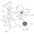
도 8 및 도 9는 본 발명의 다른 실시예에 의한 모바일 단말기의 충전 장치를 나타낸 도면이다.1 and 2 are views showing a charging device of a mobile terminal according to an embodiment of the present invention.
3 is a view showing the rotation of the terminal case on the cradle according to the present invention.
4 is a diagram illustrating a separate terminal case according to the present invention.
5 is a view illustrating a separate stand according to the present invention.
6 is a circuit diagram showing a power delay circuit unit according to the present invention.
7 is a view showing another arrangement of the second and fourth magnet according to the present invention.
8 and 9 illustrate a charging device of a mobile terminal according to another embodiment of the present invention.
이하, 첨부된 도면을 참조하여 본 발명의 바람직한 실시예를 상세하게 설명한다. 도면들 중 동일한 구성요소들은 가능한 어느 곳에서든지 동일한 부호로 표시한다. 또한 본 발명의 요지를 불필요하게 흐릴 수 있는 공지 기능 및 구성에 대한 상세한 설명은 생략한다.Hereinafter, preferred embodiments of the present invention will be described in detail with reference to the accompanying drawings. Like elements in the figures are denoted by the same reference numerals wherever possible. In the following description, well-known functions or constructions are not described in detail since they would obscure the invention in unnecessary detail.
도 1 및 도 2는 본 발명의 실시예에 의한 모바일 단말기의 충전 장치를 나타낸 외관도로서, 충전장치는 단말기 케이스(100)와 거치대(200)를 포함하여 이루어져 있다.1 and 2 is an external view showing a charging device of a mobile terminal according to an embodiment of the present invention, the charging device comprises a
단말기 케이스(100)는 탄성이 있는 폴리머 기재(substrate)나 플라스틱으로 이루어진 것으로, 하부에 모바일단말기(10)의 충전단자(15)와 접속되는 커넥터(103)가 구비되며, 배면의 표면에 동심원 형상의 패턴전극부(110)가 형성되어 커넥터(103)와 전기적으로 연결되고, 패턴전극부(110)의 내측에 제1 마그네트(130)가 내장되며, 패턴전극부(110)의 주변에 패턴전극부(110)로부터 동일한 거리에 제2 마그네트(150)가 내장되어 있다. 여기서, 제1 마그네트(130)는 패턴전극(111~114)으로 인해 패턴전극부(110)에 내장되어야 하나 제2 마그네트(150)는 케이스에 내장 또는 외부로 노출되도록 배치될 수 있다. 패턴전극부(110)는 원형 기판(117) 상에 전극이 동심원 형태로 패터닝되어 있으며, 패턴전극(111~114)은 전원단자(113(V+), 114(GND))와 데이터단자(111(D+), 112(D-))가 각각 동심원 형태로 배치될 수 있다.The
거치대(200)는 패턴전극부(110)에 대응되는 핀단자부(210)를 구비하는 데, 핀단자부(210)에는 패턴전극(111~114)과 각기 접촉되는 판스프링 형태의 핀단자(211(D+), 212(D-), 213(V+), 214(GND))가 형성되어 있다. 핀단자부(210)의 내측에는 제1 마그네트(130)와 자기적으로 결합되는 제3 마그네트(230)가 내장되며, 핀단자부(210)의 주변에 핀단자부(210)로부터 동일한 거리에 제2 마그네트(150)와 자기적으로 결합되는 제4 마그네트(250)가 내장되어 있다. 여기서, 제3 마그네트(230)는 핀단자(211~214)로 인해 핀단자부(210)에 내장되어야 하나 제4 마그네트(250)는 거치대에 내장 또는 외부로 노출되도록 배치될 수 있다.The
거치대(200)에는 외부로부터 입력된 상용 교류전원을 직류전원으로 변환하는 어댑터가 연결될 수 있다.An adapter for converting commercial AC power input from the outside into DC power may be connected to the
단말기 케이스(100)의 패턴전극부(110)의 주변에 내장되는 제2 마그네트(150)는 패턴전극부(110)의 중심을 기준으로 수평축과 수직축에 대하여 서로 대칭적으로 배치되고, 거치대(200)의 제4 마그네트(250)는 제2 마그네트(150)에 대응되는 위치에 배치된다.The
단말기 케이스(100)의 제1 마그네트(130)와 제2 마그네트(150)는 서로 다른 자극으로 배치될 수 있고, 거치대(200)의 제3 마그네트(230)와 제4 마그네트(250)도 서로 다른 자극으로 배치될 수 있다. 예컨대, 제1 마그네트(130)가 N극이면 제2 마그네트(150)는 S극일 수 있고, 제3 마그네트(230)가 S극이면 제4 마그네트(250)는 N극일 수 있다.The first magnet 130 and the
그리고, 거치대(200)의 핀단자부(210)는 내장된 판스프링의 일부(핀단자임)가 스폿 형태로 홀(218)을 통해 외부로 돌출된 형태를 가지며, 각 핀단자(211~214)는 동심원 형태의 패턴전극(111~114)에 1:1로 대응되도록 일렬로 배치될 수 있다. 또한, 핀단자(211~214)는 패턴전극(111~114)에 1:1로 대응되도록 배치되며, 상기 패턴전극(111~114)의 중심전극(111)에 대응되는 중심단자(211)으로부터 좌/우측 번갈아가며 서로 다른 거리상에 배치될 수 있다. 여기서, 접지단자(214; GND)의 경우에는 전원의 안전상 복수개의 핀으로 형성될 수 있다.In addition, the
도 3과 같이 단말기 케이스(100)가 거치대(200) 상에서 설정된 각도로 회전 가능하도록, 도 2와 같이 제2 마그네트(150)가 적어도 4개 이상 구성될 수 있으며, 각 마그네트(151~154) 간의 거리(d1, d2, d3, d4)도 서로 동일하도록 배치되어야 한다. 이때, 각 마그네트(151~154)는 중심전극(111)으로부터의 거리도 동일하게 배치되어 한다. 물론, 거치대의 제4 마그네트(250)는 제2 마그네트(150)에 대응되는 위치에 배치되어야 한다.As shown in FIG. 3, at least four
단말기 케이스(100)는 도 4에 도시된 바와 같이, 본체(101)와 배면 커버(105)로 이루어져 있다. 본체(101)의 내측과 배면 커버(105) 사이에는 일정 공간이 형성되고, 본체(101) 내측에는 제1 마그네트(130)가 지지부(140)에 의해 고정 설치되고, 제1 마그네트(130) 주변에 제1 마그네트(130)로부터 동일한 거리에 제2 마그네트(150)가 각기 설치되어 있다. 그리고, 배면 커버(105)의 중심에 관통홀(107)이 형성되어 있고, 원형 기판(117)에 형성된 동심원 형태의 패턴전극부(110)는 관통홀(107)에 끼워져 외부로 노출되며 소정의 스페이서(120)를 통해 지지부(140)에 결합된다. 지지부(140)는 본체(101) 내측에 접착제나 초음파 접착 등으로 접합되며, 지지부(140)에 스페이서(120)가 접합될 수 있다. 패턴전극부(110)의 도선(119)은 패턴전극부(110)의 하단면에서 납땜되어 전면의 커넥터(103)와 전기적으로 연결된다. 여기서, 제2 마그네트(150)의 경우 본체(101) 내측이 아니라 배면 커버(105) 측에 고정 설치될 수도 있다.As shown in FIG. 4, the
도 4에서 보듯이, 제2 마그네트(150)는 제1 마그네트(130)보다 자기력을 약화시키기 위하여 작은 사이즈로 형성될 수 있다. 만일, 제2 마그네트(150)의 자기력이 제1 마그네트(130)보다 강할 경우에는 단말기 케이스(100)가 거치대(200) 상에서 자유롭게 회전되는 것이 쉽지 않을 것이다. 즉, 제1 마그네트(130)는 단말기케이스의 회전시 회전축이 되는 것이므로, 강한 자기력을 갖는 것이 안정성을 확보할 수 있기 때문에 좋을 수 있다. 하지만, 제2 마그네트(150)의 경우에는 회전축이 아니라 회전되는 부분이므로 제1 마그네트(130)보다 약한 자기력을 갖는 것이 자유로운 회전에 있어 유리하다. 이와 같은 이유로 인해 거치대(200)의 제4 마그네트(250)도 제3 마그네트(230)보다 작은 사이즈를 사용하는 것이 바람직하다.As shown in FIG. 4, the
거치대(200)는 도 5에 도시된 바와 같이, 본체(201)와 전면 커버(205)로 이루어져 있다. 전면 커버(205)와 본체(201) 사이에는 일정 공간이 형성되고, 본체(201)에는 소정의 고정부재(220)에 의해 제3 마그네트(230)가 고정 설치되며, 핀단자부(210)는 고정부재(220)에 결합되어 본체(201)에 고정 설치된다. 전면 커버(205)의 배면에는 제3 마그네트(230) 주변에 제3 마그네트(230)로부터 동일한 거리에 제4 마그네트(250)가 각기 설치되어 있다. 그리고, 전면 커버(205)의 중심에 관통홀(207)이 형성되어 있고, 원판형의 핀단자부(210)는 전면 커버(205)의 관통홀(207)에 끼워져 외부로 노출된다. 핀단자(211~214)의 도선(219)은 각 단자의 일측에 납땜되어 본체(201)에 형성된 커넥터(203)에 전기적으로 연결된다. 상기 커넥터(203)에는 어댑터가 연결될 수 있다. 핀단자(211~214)는 패턴전극(111~114)과 마찬가지로 전원단자(213(V+), 214(GND))와 데이터단자(211(D+), 212(D-))로 형성될 수 있다.As shown in FIG. 5, the
여기서, 단말기 케이스(100)의 패턴전극부(110)와 거치대(200)의 핀단자부(210) 간의 정확한 매칭을 위하여 제1 마그네트(130)와 제3 마그네트(230) 및 제2 마그네트(150)와 제4 마그네트(250)의 정확한 배치가 가장 중요하다.Here, the first magnet 130, the
그리고, 본 발명에서는 도 6에 도시된 바와 같이, 본체(201)에 형성된 커넥터(203)와 핀단자부(210) 사이에 전원지연회로부(270)가 설치되어 있는 데, 이는 패턴전극부(110)와 핀단자부(210)가 자기력에 의해 접촉되기 때문에 접촉되는 과정에서 전극이 정확하게 매칭되지 않고 일시적으로 미스매칭되어 쇼트(short)가 발생되는 상황을 방지하기 위한 것이다. 물론, 전기적으로 쇼트가 발생되면 전원공급원인 어댑터 등의 내부 회로가 손상될 수 있다.And, in the present invention, as shown in Figure 6, the power
즉, 전원지연회로부(270)는 핀단자부(210)로 공급되는 전원을 지연시킴과 아울러 핀단자부(210)로 공급되는 전원을 감시하여 전원레벨이 일정레벨 이하일 경우 핀단자부(210)로 공급되는 전원을 차단하도록 구성되어 있는 데, 전원지연회로부(270)는 제1 스위칭소자(Q1), 제2 스위칭소자(Q2), 전원프로텍터(U1) 및 연산증폭부(U2)를 포함하여 이루어져 있다.That is, the power
제1 스위칭소자(Q1)는 본체(201)에 형성된 입력 커넥터(203)와 핀단자부(210)의 전원단자(V+) 사이의 전원라인(PL1)에 전류통로가 연결되며, 입력된 제어신호에 따라 스위칭되도록 구성되어 있다. 제2 스위칭소자(Q2)는 제1 스위칭소자(Q1)의 게이트와 접지전압(GND) 사이에 전류통로가 연결되며, 입력된 제어신호에 따라 스위칭되도록 구성되어 있다.The first switching element Q1 has a current path connected to the power line PL1 between the
전원프로텍터(U1)는 전원라인(PL1)의 전원레벨이 일정레벨 이상일 경우 제2 스위칭소자(Q2)와 제1 스위칭소자(Q1)를 순차적으로 턴온시켜 외부 전압에 따라 제1 스위칭소자(Q1)를 제어하게 된다.The power protector U1 sequentially turns on the second switching element Q2 and the first switching element Q1 when the power level of the power line PL1 is higher than or equal to a predetermined level, and accordingly to the external voltage, the first switching element Q1. To control.
연산증폭부(U2)는 제1 스위칭소자(Q1)의 양단 전압을 감지하고 양단 전압이 다를 경우 전원프로텍터(U1)를 통해 제1 스위칭소자(Q1)가 턴오프되도록 제어한다.The operational amplifier unit U2 senses the voltage across the first switching device Q1 and controls the first switching device Q1 to be turned off through the power protector U1 when the voltage across the first switching device Q1 is different.
이와 같이 구성된 전원지연회로부(270)는 어댑터나 컴퓨터로부터 커넥터(203)를 통해 전원이 인가되면, 전원프로텍터(U1)의 VDD단자로 전원이 인가되고, Vout단자를 동작시켜 제2 스위칭소자(Q2)와 제1 스위칭소자(Q1)를 순차적으로 턴온시켜 핀단자부(210)의 전원단자(V+)로 공급된다. 이때 전원프로텍터(U1)의 VDD단자에 일정전압 이상이 인가되면 설정된 시간 이후에 Vout이 제1 스위칭소자(Q1)를 턴온시키게 된다.When the power
이는, 단말기 케이스(100)의 패턴전극부(110)가 거치대(200)의 핀단자부(210)에 접촉될 때 전기적으로 단락(Short)되어 핀단자부(210)의 전원라인(PL1)의 전압 레벨이 일정레벨 이하로 떨어지면 제6 저항(R6)을 거처 전원프로텍터(U1)의 VDD단자에 인가되는 전압또한 일정레벨 이하로 인식되며, 이에 따라 Vout단자를 통해 제1 스위칭소자(Q1)가 턴오프되어 핀단자부(210)의 전원단자(V+)로 공급되는 전원이 차단된다. 이는 단말기 케이스(100)와 거치대(200)가 결합될 때 오동작하여 전원에 과부하가 걸려 전원공급원에 부하를 주어 문제가 발생할 수 있기 때문에 전원을 보호하기 위한 회로로 동작한다. 따라서, 단말기 케이스(100)와 거치대(200)의 연결시 전기적인 단락으로 인한 어댑터의 내부 회로나 컴퓨터의 USB 회로를 손상시키지 않는다.When the pattern electrode
또한, 연산증폭부(U2)는 제1 스위칭소자(Q1)의 양단 전원의 레벨을 감지하여 OUT단자를 통해 전원프로텍터(U1)의 VDD단자의 레벨을 일정 이하로 강하시키게 되며, 이에 따라 전원프로텍터(U1)의 Vout단자를 통해 제1 스위칭소자(Q1)를 턴오프시켜 어댑터나 컴퓨터의 USB포트를 보호하게 된다. 이는 핀단자부(210)의 전원단자(V+)로 전원이 인가되어 어댑터나 컴퓨터의 USB포트로 전원이 역방향으로 흘러 파손되는 것을 보호한다.In addition, the operational amplifier unit U2 senses the level of the power supply at both ends of the first switching element Q1 and lowers the level of the VDD terminal of the power protector U1 to a predetermined level or less through the OUT terminal. The first switching device Q1 is turned off through the Vout terminal of U1 to protect the adapter or the USB port of the computer. This is applied to the power supply terminal (V +) of the
한편, 도 7에 도시된 바와 같이, 제2 마그네트(150)와 제4 마그네트(250)를 도 2와 다르게 배치할 수도 있다. 단말기 케이스(100)의 패턴전극부(110)의 주변에 형성된 제2 마그네트(150)는 패턴전극부(110)를 중심으로 수직축과 수평축 방향으로 설치된 것이 도 2와 다르다. 여기서, 제2 마그네트들(151~154)은 패턴전극부(110)의 중심으로부터 동일한 거리에 배치되어 있고, 서로 인접된 마그네트 간의 거리(d1, d2, d3, d4)가 동일하게 형성되어 있다. 물론, 거치대(200)의 제4 마그네트들(251~254)도 제2 마그네트들(151~154)에 대응되는 위치에 배치되어 있다.Meanwhile, as shown in FIG. 7, the
즉, 본 발명에서는 패턴전극(110)의 중심을 기준으로 형성된 원주(ⓐ)상에 4개의 제2 마그네트(151~154)를 배치하되, 각 마그네트(151~154) 간의 거리(d1, d2, d3, d4)가 동일하게 배치하면 되는 것이다.That is, in the present invention, four
이와 같이 제2 마그네트(150)를 배치할 경우 단말기 케이스(100)를 거치대(200) 상에서 90° 각도로 회전시키는 것이 가능하다.As such, when the
도 8 및 도 9는 본 발명의 다른 실시예에 의한 모바일 단말기의 충전 장치를 나타낸 도면으로서, 충전장치는 단말기 케이스(100) 및 충전 터미널(300)을 포함하여 이루어져 있다. 도 8은 단말기 케이스(100)와 충전 터미널(300)을 분리한 상태를 나타낸 것이고, 도 9는 단말기 케이스(100)의 패턴전극부(110)에 충전 터미널(300)을 결합한 상태를 나타낸 것이다.8 and 9 are views showing a charging device of a mobile terminal according to another embodiment of the present invention, the charging device comprises a
단말기 케이스(100)는 배면에 동심원 형상의 패턴전극(111~114)이 형성되고, 상기 패턴전극부(110)의 내측에 제1 마그네트(130)가 내장되어 있다. 여기서, 단말기 케이스는 도 4와 동일하게 구성될 수 있으나, 제2 마그네트는 불필요하다.In the
충전 터미널(300)은 하우징(301) 내에 패턴전극(111~114)과 각기 접촉되는 판스프링 형태의 핀단자부(310)를 구비하며, 상기 핀단자부(310)의 내측에 상기 제1 마그네트(130)와 자기적으로 결합되는 제3 마그네트(미 도시됨)가 내장되어 있다. 충전 터미널(300)의 일측에는 케이블(370)을 통해 직류전원을 공급받는 USB커넥터(390)가 연결되어 있다.The charging
그리고, 충전 터미널(300)의 핀단자부(310)는 내장된 판스프링의 일부가 스폿 형태로 홀(318)을 통해 외부로 돌출된 형태를 가지며, 핀단자부(310)는 동심원 형태의 패턴전극부(110)에 1:1 대응되도록 일렬로 배치될 수 있다. 또한, 핀단자(311~314)는 패턴전극(111~114)에 1:1로 대응되도록 배치되며, 상기 패턴전극(111~114)의 중심전극(111)에 대응되는 중심단자(311)으로부터 좌/우측 번갈아가며 서로 다른 거리상에 배치될 수 있다. 충전 터미널(300)의 내부 구조는 기본적으로 도 5의 핀단자부(210)와 동일하게 구성될 수 있으므로, 상세한 설명은 생략한다.In addition, the
충전 터미널(300)의 경우에는 케이블의 일단에 설치된 USB커넥터(390)를 컴퓨터의 USB단자에 꽂은 후 컴퓨터에서 출력되는 직류전원으로 모바일단말기를 충전하는 것이다.In the case of the charging
이와 같이 본 발명에서는 마그네트를 이용하여 단말기와 충전 거치대를 자기적으로 결합함과 동시에 전기단자를 상호 매칭시킴에 따라 모바일단말기의 충전시에 사용상의 편의성을 향상시킬 수 있고, 모바일단말기의 충전시에 기구적인 결합이 아니라 자기적인 결합을 이용함으로써, 커넥터의 결합을 위해 별도의 노력이 불필요하고, 잦은 착탈로 인한 커넥터의 손상을 원천적으로 방지할 수 있다. 또한 마그네트의 적절한 배치를 통하여 단말기를 거치대에서 임의의 각도로 자유롭게 착탈 및 회전하는 것이 가능하여 모바일단말기의 충전시에 사용상의 편의성을 향상시킬 수 있다.As described above, in the present invention, by using a magnet, the terminal and the charging cradle are magnetically coupled to each other and the electrical terminals are matched with each other, thereby improving convenience in charging the mobile terminal, and in charging the mobile terminal. By using magnetic coupling rather than mechanical coupling, no extra effort is required for coupling the connector, and damage to the connector due to frequent detachment can be prevented. In addition, it is possible to freely detach and rotate the terminal at any angle from the cradle through the proper arrangement of the magnet can improve the ease of use when charging the mobile terminal.
또한, 본 발명에서는 마그네트를 이용한 자기적인 결합을 통해 모바일단말기를 충전함으로써, 기존의 무접점 충전기와 같이 편리하게 충전할 수 있다.In addition, in the present invention, by charging the mobile terminal through a magnetic coupling using a magnet, it can be conveniently charged like a conventional contactless charger.
상기의 본 발명은 바람직한 실시예를 중심으로 살펴보았으며, 본 발명이 속하는 기술분야에서 통상의 지식을 가진 자는 본 발명의 본질적 기술 범위 내에서 상기 본 발명의 상세한 설명과 다른 형태의 실시예들을 구현할 수 있을 것이다. 여기서 본 발명의 본질적 기술범위는 특허청구범위에 나타나 있으며, 그와 동등한 범위 내에 있는 모든 차이점은 본 발명에 포함된 것으로 해석되어야 할 것이다.
The present invention has been described with reference to the preferred embodiments, and those skilled in the art to which the present invention pertains to the detailed description of the present invention and other forms of embodiments within the essential technical scope of the present invention. Could be. Here, the essential technical scope of the present invention is shown in the claims, and all differences within the equivalent range will be construed as being included in the present invention.
10: 모바일단말기 15: 충전단자
100: 단말기 케이스 103: 커넥터
110: 패턴전극부 111~114: 패턴전극
130: 제1 마그네트 150: 제2 마그네트
200: 거치대 210: 핀단자부
211~214: 핀단자 230: 제3 마그네트
250: 제4 마그네트 270: 전원지연회로부
300: 충전 터미널10: mobile terminal 15: charging terminal
100: terminal case 103: connector
110:
130: first magnet 150: second magnet
200: holder 210: pin terminal portion
211 to 214: pin terminal 230: third magnet
250: fourth magnet 270: power delay circuit
300: charging terminal
Claims (14)
Translated fromKorean상기 패턴전극과 접촉되는 판스프링 형태의 핀단자를 구비하며, 상기 핀단자의 내측에 상기 제1 마그네트와 자기적으로 결합되는 제3 마그네트가 내장되며, 상기 단말기 케이스가 설정된 각도로 회전 가능하도록 상기 핀단자의 주변에 상기 핀단자로부터 동일한 거리에 상기 복수의 제2 마그네트와 각각 자기적으로 결합되는 복수의 제4 마그네트가 배치되는 거치대;를 포함하는 모바일 단말기의 충전 장치.
And a connector connected to the charging terminal of the mobile terminal, wherein a pattern electrode having a concentric shape is formed on the rear thereof, and is electrically connected to the connector, and a first magnet is embedded inside the pattern electrode, A terminal case having a plurality of second magnets disposed at the same distance from the pattern electrode; And
A pin spring having a plate spring shape in contact with the pattern electrode, and a third magnet magnetically coupled to the first magnet inside the pin terminal, and the terminal case is rotatable at a set angle. And a cradle having a plurality of fourth magnets magnetically coupled to the plurality of second magnets at the same distance from the pin terminals in the vicinity of the pin terminals.
상기 거치대의 제4 마그네트는 상기 핀단자의 중심을 기준으로 원주상에 서로 대칭되도록 배치되고, 상기 단말기 케이스의 제2 마그네트는 제4 마그네트에 대응되는 위치에 배치되는 모바일 단말기의 충전 장치.
The method according to claim 1,
The fourth magnet of the cradle is disposed so as to be symmetrical with each other on the circumference with respect to the center of the pin terminal, the second magnet of the terminal case is disposed in a position corresponding to the fourth magnet.
상기 단말기 케이스가 거치대 상에서 90° 각도로 회전 가능하도록, 상기 제2 마그네트는 적어도 4개 이상 배치되며, 상기 제4 마그네트는 제2 마그네트에 대응되는 위치에 배치되는, 모바일 단말기의 충전 장치.
The method according to claim 1,
At least four second magnets are disposed so that the terminal case is rotatable at an angle of 90 ° on a cradle, and the fourth magnets are disposed at positions corresponding to the second magnets.
상기 거치대는, 외부의 입력 커넥터와 상기 핀단자 사이에 설치되어 상기 핀단자로 인가되는 전원을 지연시키고, 상기 핀단자로 공급되는 전원을 감시하여 전원레벨이 일정레벨 이하일 경우 상기 핀단자로 인가되는 전원을 차단하는 전원지연회로부를 더 포함하는 모바일 단말기의 충전 장치.
The method according to claim 1,
The cradle is installed between an external input connector and the pin terminal to delay the power applied to the pin terminal, and monitor the power supplied to the pin terminal to be applied to the pin terminal when the power level is below a predetermined level. Charging device of a mobile terminal further comprising a power delay circuit unit for shutting off the power.
상기 단말기 케이스의 제1 마그네트와 제2 마그네트는 서로 다른 자극으로 배치되고, 상기 거치대의 제3 마그네트와 제4 마그네트는 서로 다른 자극으로 배치되는, 모바일 단말기의 충전 장치.
The method according to claim 1,
The first magnet and the second magnet of the terminal case is disposed with different magnetic poles, the third magnet and the fourth magnet of the cradle is disposed with different magnetic poles, the charging device of the mobile terminal.
상기 제2 마그네트는 상기 제1 마그네트보다 작은 사이즈로 형성되고,
상기 제4 마그네트는 상기 제3 마그네트보다 작은 사이즈로 형성되며,
상기 제2 마그네트와 제4 마그네트는 동일 사이즈로 형성되는, 모바일 단말기의 충전 장치.
The method according to claim 1,
The second magnet is formed in a smaller size than the first magnet,
The fourth magnet is formed in a smaller size than the third magnet,
The second magnet and the fourth magnet is the same size, the charging device of the mobile terminal.
상기 핀단자는 상기 거치대에 내장된 판스프링의 일부가 홀을 통해 외부로 돌출된 형태인 모바일 단말기의 충전 장치.
The method according to claim 1,
The pin terminal is a charging device of the mobile terminal is a portion of the leaf spring built in the cradle protrudes out through the hole.
상기 핀단자는 중심단자로부터의 거리가 각기 다르게 배치되는, 모바일 단말기의 충전 장치.
The method according to claim 1,
The pin terminal is a charging device of a mobile terminal, the distance from the center terminal is arranged differently.
상기 핀단자는 상기 패턴전극에 1:1로 대응되도록 배치되며, 상기 패턴전극의 중심전극에 대응되는 중심단자로부터 좌/우측 번갈아가며 서로 다른 거리상에 배치되는, 모바일 단말기의 충전 장치.
The method according to claim 1,
The pin terminals are disposed to correspond to the pattern electrode in a 1: 1 manner, and are arranged at different distances alternately left and right from a center terminal corresponding to the center electrode of the pattern electrode.
상기 거치대에는 교류전원을 직류전원으로 변환하여 공급하는 어댑터가 연결되는, 모바일 단말기의 충전 장치.
The method according to claim 1,
The cradle is connected to the adapter to convert the AC power to DC power supply, the charging device of the mobile terminal.
상기 패턴전극과 각기 접촉되는 판스프링 형태의 핀단자를 구비하며, 상기 핀단자의 내측에 상기 제1 마그네트와 자기적으로 결합되는 제3 마그네트가 내장되는 충전 터미널;을 포함하는 모바일 단말기의 충전 장치.
A terminal case having a connector connected to a charging terminal of a mobile terminal, and having a concentric circular pattern electrode formed on a rear surface thereof to be electrically connected to the connector, and having a first magnet embedded inside the pattern electrode; And
A charging terminal having a pin terminal having a plate spring shape in contact with each of the pattern electrodes and having a third magnet magnetically coupled to the first magnet inside the pin terminal; .
상기 충전 터미널의 일측에 직류전원을 공급받는 USB커넥터가 연결된, 모바일 단말기의 충전 장치.
The method of claim 11,
A charging device of a mobile terminal is connected to a USB connector receiving DC power to one side of the charging terminal.
상기 핀단자는 상기 충전 터미널에 내장된 판스프링의 일부가 홀을 통해 외부로 돌출된 형태인 모바일 단말기의 충전 장치.
The method of claim 11,
The pin terminal is a charging device of the mobile terminal is a portion of the leaf spring built in the charging terminal protrudes out through the hole.
상기 핀단자는 상기 패턴전극에 1:1로 대응되도록 일렬로 배치되며, 상기 패턴전극의 중심전극에 대응되는 중심단자로부터 좌/우측 번갈아가며 서로 다른 거리상에 배치되는, 모바일 단말기의 충전 장치.The method of claim 11,
The pin terminals are arranged in a line so as to correspond to the pattern electrode in a 1: 1 manner, and are arranged on different distances alternately left and right from a center terminal corresponding to the center electrode of the pattern electrode.
Priority Applications (6)
| Application Number | Priority Date | Filing Date | Title |
|---|---|---|---|
| KR1020120074679AKR101204510B1 (en) | 2012-07-09 | 2012-07-09 | Charging device for mobile phone |
| JP2014540931AJP5845359B2 (en) | 2012-07-09 | 2012-10-05 | Mobile device charger |
| PCT/KR2012/008065WO2014010781A1 (en) | 2012-07-09 | 2012-10-05 | Charging apparatus for mobile device |
| US14/411,857US9673647B2 (en) | 2012-07-09 | 2012-10-05 | Charging apparatus for mobile device |
| CN201610258369.1ACN105932728A (en) | 2012-07-09 | 2012-12-03 | Charging apparatus for mobile device |
| CN201210509431.1ACN103545857B (en) | 2012-07-09 | 2012-12-03 | Charging equipment for mobile devices |
Applications Claiming Priority (1)
| Application Number | Priority Date | Filing Date | Title |
|---|---|---|---|
| KR1020120074679AKR101204510B1 (en) | 2012-07-09 | 2012-07-09 | Charging device for mobile phone |
Publications (1)
| Publication Number | Publication Date |
|---|---|
| KR101204510B1true KR101204510B1 (en) | 2012-11-26 |
Family
ID=47565277
Family Applications (1)
| Application Number | Title | Priority Date | Filing Date |
|---|---|---|---|
| KR1020120074679AActiveKR101204510B1 (en) | 2012-07-09 | 2012-07-09 | Charging device for mobile phone |
Country Status (5)
| Country | Link |
|---|---|
| US (1) | US9673647B2 (en) |
| JP (1) | JP5845359B2 (en) |
| KR (1) | KR101204510B1 (en) |
| CN (2) | CN105932728A (en) |
| WO (1) | WO2014010781A1 (en) |
Cited By (24)
| Publication number | Priority date | Publication date | Assignee | Title |
|---|---|---|---|---|
| JPS6180881A (en)* | 1984-09-28 | 1986-04-24 | Toshiba Corp | semiconductor laser equipment |
| KR101265730B1 (en) | 2013-02-20 | 2013-05-21 | (주)에스피에스 | Magnetic connector module having a circuit for restricting power supply |
| KR101343103B1 (en) | 2013-07-02 | 2013-12-20 | (주)에스피에스 | Charging system having a circuit for delaying power supply |
| KR101344452B1 (en) | 2013-02-22 | 2013-12-26 | 덕일산업 주식회사 | Apparatus for charging portable devices using a charging indicator |
| KR101344451B1 (en) | 2013-02-22 | 2013-12-26 | 덕일산업 주식회사 | Charging apparatus of portable device |
| KR101391547B1 (en)* | 2013-08-29 | 2014-05-27 | 임영철 | Chargible smart phone cradle for car |
| KR101404784B1 (en) | 2013-04-11 | 2014-06-12 | (주)대한특수금속 | magnetic type interface apparatus |
| KR200474737Y1 (en) | 2012-11-16 | 2014-10-10 | (주)에스피에스 | Charging cradle for mobile phone |
| KR101459991B1 (en)* | 2014-07-25 | 2014-11-07 | 임영철 | Case and cradle with rotary contact |
| WO2015009578A1 (en)* | 2013-07-15 | 2015-01-22 | Toshiba Global Commerce Solutions Holdings Corporation | A display assembly having graduated magnetic fastening characteristics |
| WO2015075724A1 (en)* | 2013-11-24 | 2015-05-28 | HAMAMA, Yaniv | Slim-form charger for a mobile phone |
| CN105322324A (en)* | 2015-05-29 | 2016-02-10 | 维沃移动通信有限公司 | Symmetric adsorption connector and connection method thereof |
| KR101602101B1 (en)* | 2015-03-23 | 2016-03-10 | (주)대한특수금속 | Portable charging apparatus and fashion supplies with thereof |
| WO2016064025A1 (en)* | 2014-10-23 | 2016-04-28 | 임영철 | Cellular phone cradle system having rotary contact part |
| KR20160001886U (en) | 2014-11-25 | 2016-06-02 | (주)에스피에스 | Thin film type magnetic connector module |
| KR101627460B1 (en)* | 2015-04-02 | 2016-06-07 | 임영철 | Rotatable charging system for portable device |
| KR200482089Y1 (en)* | 2016-03-28 | 2016-12-14 | 윤재원 | Charging holder for portable terminal |
| KR20170037697A (en) | 2015-09-25 | 2017-04-05 | 주식회사 블랙야크 | Connector cage for smart clothes and control device for smart clothes using the same |
| WO2017057894A1 (en)* | 2015-09-30 | 2017-04-06 | (주)에스피에스 | Charging stand, and charging device for mobile terminal |
| WO2018182246A1 (en)* | 2017-03-28 | 2018-10-04 | (주)오상헬스케어 | Connector module and electronic device comprising same |
| US10159159B2 (en) | 2016-05-27 | 2018-12-18 | Mobile Synergy 26 International Limited | Multifunctional connection systems for various devices and methods of use thereof |
| KR102400959B1 (en)* | 2020-12-18 | 2022-05-25 | 장춘만 | Parking and charging apparatus for personal mobility |
| KR20220076220A (en) | 2020-11-30 | 2022-06-08 | (주) 블랙야크 아이앤씨 | Thermal clothing that is durable and easy to maintain |
| KR20230052467A (en)* | 2021-10-13 | 2023-04-20 | 김훈모 | Quick charging holder of smart device for two wheeled vehicle using magnet |
Families Citing this family (46)
| Publication number | Priority date | Publication date | Assignee | Title |
|---|---|---|---|---|
| US10135304B2 (en) | 2013-09-05 | 2018-11-20 | Lg Innotek Co., Ltd. | Supporter |
| KR101558051B1 (en)* | 2013-11-04 | 2015-10-06 | 삼성전기주식회사 | Board assembly and Electric device including the same |
| US10050658B2 (en) | 2014-02-24 | 2018-08-14 | National Products, Inc. | Docking sleeve with electrical adapter |
| JP6283253B2 (en)* | 2014-04-18 | 2018-02-21 | 株式会社アスタリスク | Function expansion device and charging system for function expansion device |
| US9531118B2 (en) | 2014-07-10 | 2016-12-27 | Norman R. Byrne | Electrical power coupling with magnetic connections |
| WO2016031122A1 (en)* | 2014-08-26 | 2016-03-03 | ソニー株式会社 | Connector and portable device |
| CN104201510B (en)* | 2014-09-10 | 2016-04-06 | 南京物联传感技术有限公司 | The syndeton of product and support |
| KR101638940B1 (en)* | 2015-03-27 | 2016-07-13 | (주)에스피에스 | Compact image input device having a double bond structure |
| CN107736005B (en) | 2015-06-29 | 2021-04-13 | 通利台有限公司 | Rotary terminal device for portable terminal and desk lamp |
| FR3041170B1 (en)* | 2015-09-14 | 2018-12-07 | Electricite De France | SYSTEM AND METHOD FOR RECHARGING NOMADIC ELECTRONIC DEVICES, AND ADAPTER FOR SUCH A SYSTEM |
| WO2017085663A1 (en)* | 2015-11-19 | 2017-05-26 | King Abdullah University Of Science And Technology | Flat-port connectors |
| CN105514681A (en)* | 2016-01-18 | 2016-04-20 | 普联技术有限公司 | Magnetic type connector and mobile electronic device with same |
| US10177507B2 (en) | 2016-02-12 | 2019-01-08 | Norman R. Byrne | Electrical power load switch with connection sensor |
| CN105559776B (en)* | 2016-03-04 | 2018-08-17 | 武汉明德生物科技股份有限公司 | A kind of mobile ECG collection device |
| US10027059B2 (en) | 2016-05-02 | 2018-07-17 | Norman R. Byrne | Twist-lock electrical connector |
| CN106331930B (en)* | 2016-09-30 | 2023-06-20 | 歌尔科技有限公司 | Charging box of wireless earphone and wireless earphone adapting to charging box |
| MX371369B (en) | 2016-10-07 | 2020-01-28 | Norman R Byrne | Electrical power cord with intelligent switching. |
| KR101874204B1 (en)* | 2016-12-13 | 2018-07-03 | 한국항공우주연구원 | Drone's landing system |
| WO2018144766A1 (en)* | 2017-02-03 | 2018-08-09 | Sps Inc. | Rack for electrically connecting mobile electronic device |
| CN109390994B (en)* | 2017-08-11 | 2023-08-11 | 手持产品公司 | Soft power start solution based on POGO connector |
| CN109462268A (en)* | 2017-08-23 | 2019-03-12 | 中国探针股份有限公司 | 360-degree multi-directional magnetic attraction type socket |
| TWI638257B (en)* | 2017-11-20 | 2018-10-11 | 李淯任 | Transfer charging group |
| US20190372377A1 (en)* | 2018-06-01 | 2019-12-05 | Flag Acquisition, Llc | Systems and methods for charging one or more electronic devices |
| US10742048B2 (en)* | 2018-08-02 | 2020-08-11 | Fossil Group, Inc. | Wearable electronic device with a caseback having multiple, arc-shaped, ferrous, metal contacts |
| US11424561B2 (en) | 2019-07-03 | 2022-08-23 | Norman R. Byrne | Outlet-level electrical energy management system |
| CN211018349U (en)* | 2019-12-25 | 2020-07-14 | 展讯通信(深圳)有限公司 | Charger, equipment to be charged and charging system |
| US20210295728A1 (en)* | 2020-03-19 | 2021-09-23 | Elnaz Sarrafzadeh | Artificial Intelligent (AI) Apparatus and System to Educate Children in Remote and Homeschool Setting |
| DE102020134363B4 (en) | 2020-12-21 | 2024-02-15 | Bury Sp. Z. O. O. | Loading facility |
| USD951863S1 (en)* | 2021-04-14 | 2022-05-17 | Cyspo Technology (Shen Zhen) Co., Ltd. | Wireless charger |
| JP2022164189A (en)* | 2021-04-16 | 2022-10-27 | 株式会社ジャパンディスプレイ | Power supply structure |
| JP7687734B2 (en)* | 2021-06-09 | 2025-06-03 | エスピーエス インコーポレイテッド | Cradle for holding smart devices and battery connected thereto |
| USD974296S1 (en)* | 2021-07-14 | 2023-01-03 | Fumin Zhang | Wireless charger |
| USD1024945S1 (en)* | 2021-10-08 | 2024-04-30 | Shenzhen Yifeng Intelligent Technology Co., Ltd. | Wireless charger |
| DE102021128858B3 (en) | 2021-11-05 | 2023-02-02 | Bury Sp.Z.O.O | Inductive charger and set of inductive charger and plastic insert |
| CN116280338A (en)* | 2021-12-08 | 2023-06-23 | 海鹰航空通用装备有限责任公司 | Mooring floating platform and unmanned aerial vehicle system with same |
| USD1000382S1 (en)* | 2022-01-18 | 2023-10-03 | Rfa Brands, Llc | Wireless charging stand |
| USD1024949S1 (en)* | 2022-01-21 | 2024-04-30 | Dongguan Weizhichuang Technology Co., Ltd. | Wireless charger |
| USD1053128S1 (en)* | 2022-04-15 | 2024-12-03 | Chang Dong | Wireless charger |
| USD1022896S1 (en)* | 2022-06-09 | 2024-04-16 | Shenzhen Yifeng Intelligent Technology Co., Ltd. | Wireless charger |
| USD1030656S1 (en)* | 2022-07-05 | 2024-06-11 | Sandmarc, Llc | Charging dock |
| USD1046770S1 (en)* | 2022-07-15 | 2024-10-15 | Huizhou Waweis Technology Co., Ltd. | Wireless charger |
| USD1019549S1 (en)* | 2022-08-12 | 2024-03-26 | Junjie Lin | Wireless charger |
| USD995424S1 (en)* | 2023-04-28 | 2023-08-15 | Shenzhen Guanyuan Tianye Technology Co., Ltd. | Wireless charger |
| US12298809B2 (en) | 2023-07-05 | 2025-05-13 | National Products, Inc. | Heating module for electronic device dock and methods of making and using |
| KR102841042B1 (en)* | 2024-02-01 | 2025-07-30 | 구교빈 | A rechargeable cell phone case with built-in wireless charging coil detachable with electronic cigarette |
| USD1062628S1 (en)* | 2024-09-29 | 2025-02-18 | Lianggui Cao | Wireless charging station |
Citations (1)
| Publication number | Priority date | Publication date | Assignee | Title |
|---|---|---|---|---|
| KR101162552B1 (en) | 2005-06-30 | 2012-07-05 | 엘지전자 주식회사 | Charging system for portable phone |
Family Cites Families (16)
| Publication number | Priority date | Publication date | Assignee | Title |
|---|---|---|---|---|
| JPH0834114B2 (en) | 1987-04-30 | 1996-03-29 | ソニー株式会社 | Connector device |
| JP2001352597A (en)* | 2000-06-09 | 2001-12-21 | Nec Saitama Ltd | Electro/acoustic converter having back terminal |
| WO2003043161A1 (en)* | 2001-11-15 | 2003-05-22 | Min Kyiu Sin | Charger for mobile telephone |
| KR20050089360A (en)* | 2004-03-04 | 2005-09-08 | 주식회사 아트랑 | Mobile phone display stand |
| JP4639215B2 (en) | 2007-05-25 | 2011-02-23 | シャープ株式会社 | Desktop charger |
| US7841776B2 (en) | 2008-09-30 | 2010-11-30 | Apple Inc. | Magnetic connector with optical signal path |
| US8148946B2 (en)* | 2008-10-10 | 2012-04-03 | Mitsumi Electric Co., Ltd. | Battery pack having protection circuit for secondary battery |
| US20110192857A1 (en) | 2008-12-18 | 2011-08-11 | Wayne Philip Rothbaum | Magnetically Attached Accessories (For A Case) for a Portable Electronics Device |
| KR101047448B1 (en)* | 2009-07-30 | 2011-07-07 | (주)대성이엔티 | Multi charging device with speaker function |
| CN201584823U (en)* | 2009-09-25 | 2010-09-15 | 北京华旗资讯数码科技有限公司 | Wireless power supply device |
| US8121618B2 (en)* | 2009-10-28 | 2012-02-21 | Digimarc Corporation | Intuitive computing methods and systems |
| KR101116159B1 (en) | 2010-04-29 | 2012-03-06 | 아이볼타(주) | Terminal connecting module and terminal connector having the same |
| US8576034B2 (en) | 2010-07-21 | 2013-11-05 | Apple Inc. | Alignment and connection for devices |
| KR101246878B1 (en)* | 2011-02-11 | 2013-03-25 | (주)에스피에스 | Charging device using magnet |
| KR20120129488A (en)* | 2011-05-20 | 2012-11-28 | (주)에스피에스 | Magnetic connecting device |
| US8553408B2 (en)* | 2011-09-06 | 2013-10-08 | Dana Innovations | Charging docking system |
- 2012
- 2012-07-09KRKR1020120074679Apatent/KR101204510B1/enactiveActive
- 2012-10-05WOPCT/KR2012/008065patent/WO2014010781A1/enactiveApplication Filing
- 2012-10-05JPJP2014540931Apatent/JP5845359B2/enactiveActive
- 2012-10-05USUS14/411,857patent/US9673647B2/enactiveActive
- 2012-12-03CNCN201610258369.1Apatent/CN105932728A/enactivePending
- 2012-12-03CNCN201210509431.1Apatent/CN103545857B/enactiveActive
Patent Citations (1)
| Publication number | Priority date | Publication date | Assignee | Title |
|---|---|---|---|---|
| KR101162552B1 (en) | 2005-06-30 | 2012-07-05 | 엘지전자 주식회사 | Charging system for portable phone |
Cited By (37)
| Publication number | Priority date | Publication date | Assignee | Title |
|---|---|---|---|---|
| JPS6180881A (en)* | 1984-09-28 | 1986-04-24 | Toshiba Corp | semiconductor laser equipment |
| KR200474737Y1 (en) | 2012-11-16 | 2014-10-10 | (주)에스피에스 | Charging cradle for mobile phone |
| US9088097B2 (en) | 2013-02-20 | 2015-07-21 | Sps, Inc. | Magnetic connector module having power supply blocking circuit |
| JP2014160637A (en)* | 2013-02-20 | 2014-09-04 | Sps Inc | Magnetic connector module having power supply blocking circuit |
| KR101265730B1 (en) | 2013-02-20 | 2013-05-21 | (주)에스피에스 | Magnetic connector module having a circuit for restricting power supply |
| JP2015111590A (en)* | 2013-02-20 | 2015-06-18 | エスピーエス インコーポレイテッド | Magnetic connector module having power supply blocking circuit |
| EP2770586A3 (en)* | 2013-02-20 | 2014-10-15 | Sps, Inc. | Magnetic connector module having power supply blocking circuit |
| EP2770586A2 (en) | 2013-02-20 | 2014-08-27 | Sps, Inc. | Magnetic connector module having power supply blocking circuit |
| KR101344452B1 (en) | 2013-02-22 | 2013-12-26 | 덕일산업 주식회사 | Apparatus for charging portable devices using a charging indicator |
| KR101344451B1 (en) | 2013-02-22 | 2013-12-26 | 덕일산업 주식회사 | Charging apparatus of portable device |
| KR101404784B1 (en) | 2013-04-11 | 2014-06-12 | (주)대한특수금속 | magnetic type interface apparatus |
| WO2014168337A1 (en)* | 2013-04-11 | 2014-10-16 | (주)대한특수금속 | Magnetic interface |
| KR101343103B1 (en) | 2013-07-02 | 2013-12-20 | (주)에스피에스 | Charging system having a circuit for delaying power supply |
| CN104167622A (en)* | 2013-07-02 | 2014-11-26 | 世派电子株式会社 | Charge system having a circuit for delaying power supply |
| DE102014109278A1 (en) | 2013-07-02 | 2015-01-08 | Sps Inc. | Charging system with a circuit for delaying the power supply |
| US9537334B2 (en) | 2013-07-02 | 2017-01-03 | Sps Inc. | Charging system having circuit for delaying power supply |
| WO2015009578A1 (en)* | 2013-07-15 | 2015-01-22 | Toshiba Global Commerce Solutions Holdings Corporation | A display assembly having graduated magnetic fastening characteristics |
| KR101391547B1 (en)* | 2013-08-29 | 2014-05-27 | 임영철 | Chargible smart phone cradle for car |
| WO2015075724A1 (en)* | 2013-11-24 | 2015-05-28 | HAMAMA, Yaniv | Slim-form charger for a mobile phone |
| US10468894B2 (en) | 2013-11-24 | 2019-11-05 | Soloqi Corp. | Charger for a mobile device and magnetic sticker usable therewith |
| KR101459991B1 (en)* | 2014-07-25 | 2014-11-07 | 임영철 | Case and cradle with rotary contact |
| WO2016064025A1 (en)* | 2014-10-23 | 2016-04-28 | 임영철 | Cellular phone cradle system having rotary contact part |
| KR20160001886U (en) | 2014-11-25 | 2016-06-02 | (주)에스피에스 | Thin film type magnetic connector module |
| KR101602101B1 (en)* | 2015-03-23 | 2016-03-10 | (주)대한특수금속 | Portable charging apparatus and fashion supplies with thereof |
| KR101627460B1 (en)* | 2015-04-02 | 2016-06-07 | 임영철 | Rotatable charging system for portable device |
| CN105322324A (en)* | 2015-05-29 | 2016-02-10 | 维沃移动通信有限公司 | Symmetric adsorption connector and connection method thereof |
| KR20170037697A (en) | 2015-09-25 | 2017-04-05 | 주식회사 블랙야크 | Connector cage for smart clothes and control device for smart clothes using the same |
| WO2017057894A1 (en)* | 2015-09-30 | 2017-04-06 | (주)에스피에스 | Charging stand, and charging device for mobile terminal |
| KR20170038358A (en) | 2015-09-30 | 2017-04-07 | (주)에스피에스 | Charging device for mobile terminal |
| KR101734399B1 (en)* | 2015-09-30 | 2017-05-12 | (주)에스피에스 | Charging device for mobile terminal |
| KR200482089Y1 (en)* | 2016-03-28 | 2016-12-14 | 윤재원 | Charging holder for portable terminal |
| US10159159B2 (en) | 2016-05-27 | 2018-12-18 | Mobile Synergy 26 International Limited | Multifunctional connection systems for various devices and methods of use thereof |
| WO2018182246A1 (en)* | 2017-03-28 | 2018-10-04 | (주)오상헬스케어 | Connector module and electronic device comprising same |
| KR20220076220A (en) | 2020-11-30 | 2022-06-08 | (주) 블랙야크 아이앤씨 | Thermal clothing that is durable and easy to maintain |
| KR102400959B1 (en)* | 2020-12-18 | 2022-05-25 | 장춘만 | Parking and charging apparatus for personal mobility |
| KR20230052467A (en)* | 2021-10-13 | 2023-04-20 | 김훈모 | Quick charging holder of smart device for two wheeled vehicle using magnet |
| KR102650121B1 (en)* | 2021-10-13 | 2024-03-20 | 김훈모 | Quick charging holder of smart device for two wheeled vehicle using magnet |
Also Published As
| Publication number | Publication date |
|---|---|
| WO2014010781A1 (en) | 2014-01-16 |
| US20150171649A1 (en) | 2015-06-18 |
| JP2015502128A (en) | 2015-01-19 |
| CN103545857A (en) | 2014-01-29 |
| CN103545857B (en) | 2016-12-07 |
| US9673647B2 (en) | 2017-06-06 |
| CN105932728A (en) | 2016-09-07 |
| JP5845359B2 (en) | 2016-01-20 |
Similar Documents
| Publication | Publication Date | Title |
|---|---|---|
| KR101204510B1 (en) | Charging device for mobile phone | |
| KR200467719Y1 (en) | Back cover for mobile phone | |
| US8248025B2 (en) | Charging system capable of charging electronic device by electromagnetic induction | |
| KR101822855B1 (en) | Portable charging case module | |
| EP2770586B1 (en) | Magnetic connector module having power supply blocking circuit | |
| US8237401B2 (en) | Recharging system and electronic device | |
| US20110227527A1 (en) | Wireless charging kit for portable electronic device | |
| CN108292849B (en) | System and method for recharging a roaming device, and adapter for such a system | |
| US9035602B2 (en) | Wireless battery charger for mobile devices and method thereof | |
| KR101718729B1 (en) | Structure for charging and supporting mobile-phone | |
| US20200313451A1 (en) | Multi-purpose electrical charging structure | |
| KR20170000162U (en) | Connetion tip and protecting case for portable device | |
| US8981713B2 (en) | Charging apparatus using pad type electrode contact point | |
| CN104617632B (en) | Charging device adaptable to different electronic devices, charging method thereof, and electronic device | |
| CN105762874A (en) | Multi-USB output interface charger | |
| KR200474737Y1 (en) | Charging cradle for mobile phone | |
| JP3190493U (en) | DC magnetic connector | |
| CN204441950U (en) | Charging device and electronic equipment that can be adapted to different electronic equipment | |
| CN203014115U (en) | Mobile equipment adapter | |
| KR20170027347A (en) | wireless charger | |
| KR101620450B1 (en) | Wire and wireless recharging apparatus | |
| CN203193347U (en) | Wireless charging device and mobile terminal | |
| TWI636630B (en) | 360 degree multi-directional magnetic socket | |
| CN222763286U (en) | A split AC to DC charger | |
| CN220172894U (en) | Combined charging device |
Legal Events
| Date | Code | Title | Description |
|---|---|---|---|
| A201 | Request for examination | ||
| PA0109 | Patent application | St.27 status event code:A-0-1-A10-A12-nap-PA0109 | |
| PA0201 | Request for examination | St.27 status event code:A-1-2-D10-D11-exm-PA0201 | |
| A302 | Request for accelerated examination | ||
| PA0302 | Request for accelerated examination | St.27 status event code:A-1-2-D10-D17-exm-PA0302 St.27 status event code:A-1-2-D10-D16-exm-PA0302 | |
| E902 | Notification of reason for refusal | ||
| PE0902 | Notice of grounds for rejection | St.27 status event code:A-1-2-D10-D21-exm-PE0902 | |
| P11-X000 | Amendment of application requested | St.27 status event code:A-2-2-P10-P11-nap-X000 | |
| P13-X000 | Application amended | St.27 status event code:A-2-2-P10-P13-nap-X000 | |
| E701 | Decision to grant or registration of patent right | ||
| PE0701 | Decision of registration | St.27 status event code:A-1-2-D10-D22-exm-PE0701 | |
| GRNT | Written decision to grant | ||
| PR0701 | Registration of establishment | St.27 status event code:A-2-4-F10-F11-exm-PR0701 | |
| PR1002 | Payment of registration fee | St.27 status event code:A-2-2-U10-U11-oth-PR1002 Fee payment year number:1 | |
| PG1601 | Publication of registration | St.27 status event code:A-4-4-Q10-Q13-nap-PG1601 | |
| R18-X000 | Changes to party contact information recorded | St.27 status event code:A-5-5-R10-R18-oth-X000 | |
| FPAY | Annual fee payment | Payment date:20151119 Year of fee payment:4 | |
| PR1001 | Payment of annual fee | St.27 status event code:A-4-4-U10-U11-oth-PR1001 Fee payment year number:4 | |
| PN2301 | Change of applicant | St.27 status event code:A-5-5-R10-R13-asn-PN2301 St.27 status event code:A-5-5-R10-R11-asn-PN2301 | |
| R18-X000 | Changes to party contact information recorded | St.27 status event code:A-5-5-R10-R18-oth-X000 | |
| FPAY | Annual fee payment | Payment date:20161117 Year of fee payment:5 | |
| PR1001 | Payment of annual fee | St.27 status event code:A-4-4-U10-U11-oth-PR1001 Fee payment year number:5 | |
| FPAY | Annual fee payment | Payment date:20171018 Year of fee payment:6 | |
| PR1001 | Payment of annual fee | St.27 status event code:A-4-4-U10-U11-oth-PR1001 Fee payment year number:6 | |
| FPAY | Annual fee payment | Payment date:20181002 Year of fee payment:7 | |
| PR1001 | Payment of annual fee | St.27 status event code:A-4-4-U10-U11-oth-PR1001 Fee payment year number:7 | |
| FPAY | Annual fee payment | Payment date:20190820 Year of fee payment:8 | |
| PR1001 | Payment of annual fee | St.27 status event code:A-4-4-U10-U11-oth-PR1001 Fee payment year number:8 | |
| PR1001 | Payment of annual fee | St.27 status event code:A-4-4-U10-U11-oth-PR1001 Fee payment year number:9 | |
| PR1001 | Payment of annual fee | St.27 status event code:A-4-4-U10-U11-oth-PR1001 Fee payment year number:10 | |
| PR1001 | Payment of annual fee | St.27 status event code:A-4-4-U10-U11-oth-PR1001 Fee payment year number:11 | |
| R18-X000 | Changes to party contact information recorded | St.27 status event code:A-5-5-R10-R18-oth-X000 | |
| PR1001 | Payment of annual fee | St.27 status event code:A-4-4-U10-U11-oth-PR1001 Fee payment year number:12 | |
| PR1001 | Payment of annual fee | St.27 status event code:A-4-4-U10-U11-oth-PR1001 Fee payment year number:13 | |
| PR1001 | Payment of annual fee | St.27 status event code:A-4-4-U10-U11-oth-PR1001 Fee payment year number:14 |